Vogt Valves - AIV, Inc
77
Vogt Valves Catalog and Application Manual Vogt Valves VVACT0000-01 (Replaces VV200)
Transcript of Vogt Valves - AIV, Inc

Vogt Valves
Catalog and ApplicationManual
Vogt ValvesVVACT0000-01(Replaces VV200)

Forged Steel Valves and Fittings
Page
Index by Valve Type . . . . . . . . . . . . . . . . . . . . . . . . . . . . . . . i - vTable of Contents. . . . . . . . . . . . . . . . . . . . . . . . . . . . . . . . . . . . 1Index . . . . . . . . . . . . . . . . . . . . . . . . . . . . . . . . . . . . . . . . . . . 2 - 3Description of No. System . . . . . . . . . . . . . . . . . . . . . . . . . . . . 4Gate Valves . . . . . . . . . . . . . . . . . . . . . . . . . . . . . . . . . . . . . 5 - 43Nuclear . . . . . . . . . . . . . . . . . . . . . . . . . . . . . . . . . . . . . . . . . . . 44Sour Service. . . . . . . . . . . . . . . . . . . . . . . . . . . . . . . . . . . . . . . 45Globe Valves . . . . . . . . . . . . . . . . . . . . . . . . . . . . . . . . . . . 46 - 87Auxiliary Operators . . . . . . . . . . . . . . . . . . . . . . . . . . . . . . . . . 88Check Valves. . . . . . . . . . . . . . . . . . . . . . . . . . . . . . . . . . 89 - 111Engineering Tables. . . . . . . . . . . . . . . . . . . . . . . . . . . . 112 - 123Fittings & Unions . . . . . . . . . . . . . . . . . . . . . . . . . . . . . 124 - 132Limited Warranty . . . . . . . . . . . . . . . . . . . . . . . . . . . . . . . . . . 133Glossary, Standards. . . . . . . . . . . . . . . . . . . . . . . . . . . 134 - 136Care & Maintenance . . . . . . . . . . . . . . . . . . . . . . . . . . 137 - 139Spare Parts . . . . . . . . . . . . . . . . . . . . . . . . . . . . . . . . . 140 - 143Standards, Data, etc. . . . . . . . . . . . . . . . . . . . . . . . . . . 144 - 149

Press. Class Material Bonnet Joint End Connection Bonnet Type SERIES150 A105 Bolted Flanged OS&Y 353
Butt Weld OS&Y BW353THd/SW OS&Y See Class 800
A182 F316/F316 L Bolted Flanged OS&Y 358A350 LF2 Bolted Flanged OS&Y 32353
300 A105 Bolted Flanged OS&Y 363Butt Weld OS&Y BW363Thd/SW OS&Y See Class 800
A182 F316/F316 L Bolted Flanged OS&Y 368A350 LF2 Bolted Flanged OS&Y 32363
600 A105 Bolted Flanged OS&Y 373, 13373, 11403Butt Weld OS&Y BW373Thd/SW OS&Y See Class 800
A182 F316/F316 L Bolted Flanged OS&Y 378A350 LF2 Bolted Flanged OS&Y 32373
Threaded OS&Y 12111, 13111, 11103ISS 12161
Socket Weld OS&Y SW12111, SW13111, SW11103Bolted ISS SW12161
Male Thd x Fem Thd OS&Y TT12111Male Soc x Fem Thd OS&Y ST 12111Male Cpt x Fem Thd OS&Y CT12111
A105 Threaded OS&Y 2801, 2801BISS 2811
Socket Weld OS&Y SW2801, SW2801B Weld ISS SW2811
Male Thd x Fem Thd OS&Y TT2801ISS TT2811
Male Soc x Fem Thd OS&Y ST2801Male Cpt x Fem Thd OS&Y CT 2801, CT 2901
Union Threaded ISS 59851800 Socket Weld ISS SW59851
A350 LF2 Bolted Threaded OS&Y 32111Socket Weld OS&Y SW32111
Bolted Threaded OS&Y 12401, 13401Socket Weld OS&Y SW12401, SW13401Threaded OS&Y 2831Socket Weld OS&Y SW2831
A182 F3/F316L Weld Male Thd x Fem Thd OS&Y TT2831Male Soc x Fem Thd OS&Y ST2831Male Cpt x Fem Thd OS&Y CT2831
Union Threaded ISS 59951Socket Weld ISS SW59951
A182 F316H Bolted Threaded OS&Y 82401Socket Weld OS&Y SW82401
A182 F5 Bolted Threaded OS&Y 12421Socket Weld OS&Y SW12421
A182 F9 Bolted Threaded OS&Y 12921Socket Weld OS&Y SW12921
i
Gate Valve Index

ii
Globe Valve Index
Press. Class Material Bonnet Joint End Connection Bonnet Type SERIES800 (cont.) A182 F11, CL2 Bolted Threaded OS&Y 12321
Socket Weld OS&Y SW12321A182 F22 CL 3 Bolted Threaded OS&Y 12521
Socket Weld OS&Y SW12521Threaded OS&Y 15111, 16111, 1033, 1043
Bolted Socket Weld OS&Y SW15111, SW16111, SW1043, SW1033A105 Flanged OS&Y 15373, 11603, 11683
Weld Threaded OS&Y 15801Socket Weld OS&Y SW15801Male Cpt x Fem Thd OS&Y ST15801
1500 A350 LF2 Bolted Threaded OS&Y 35111Socket Weld OS&Y SW35111
A182 F316/F316L Bolted Threaded OS&Y 15401Socket Weld OS&Y SW15401
Weld Threaded OS&Y 15831Socket Weld OS&Y SW15831
A182 F11, CL.2 Bolted Threaded OS&Y 15321Socket Weld OS&Y SW15321
A105 Welded Threaded OS&Y 66703Socket Weld OS&Y SW66703
2500 A182 F11, CL2 Welded Threaded OS&Y 66713Socket Weld OS&Y SW66713
A182 F22, CL.3 Welded Socket Weld OS&Y SW66773
Press. Class Material Bonnet Joint End Connection Bonnet Type SERIES150 A105 Bolted Flanged OS&Y 473, 473B
Bolted THd/SW OS&Y See Class 800A350 LF2 Bolted Flanged OS&Y 32473
300 A105 Bolted Flanged OS&Y 483, 483B, 22483CLBolted Thd/SW OS&Y See Class 800
A350 LF2 Bolted Flanged OS&Y 32483600 A105 Bolted Flanged OS&Y 493, 493B, 22493CL,
22493MT, 10403Bolted Thd/SW OS&Y See Class 800
A350 LF2 Bolted Flanged OS&Y 32493800 OS&Y 12141, 12141B, 13141, 22141
Threaded 12443, 22461, 10103, 1971ISS 12181
SW12141, 12141B, SW13141Bolted Socket Weld OS&Y SW22141, SW12443, SW22461
SW10103, SW1971ISS SW12181
A105 Male Thd x Fem Thd OS&Y TT12141Male Soc x Fem Thd OS&Y ST 12141Male Cpt x Fem Thd OS&Y CT12141
Weld Threaded OS&Y 2821, 810Socket Weld OS&Y SW2821, SW810
Gate Valve Index (cont.)

iii
Globe Valve Index (cont.)
Press. Class Material Bonnet Joint End Connection Bonnet Type SERIES800 (cont.) Threaded OS&Y 801
Union ISS 851Socket Weld OS&Y SW801
ISS SW851A182 F316/F316L Bolted Threaded OS&Y 12501
Socket Weld OS&Y SW12501A182 F316H Bolted Threaded OS&Y 82501
Socket Weld OS&Y SW82501Bolted Socket Weld OS&Y SW12351
A182 F11, CL. 2 Weld Threaded OS&Y 811Socket Weld OS&Y SW811
Bolted Socket Weld OS&Y 12551A182 F22, CL. 3 Weld Threaded OS&Y 822
Socket Weld OS&Y SW822A350 LF2 Bolted Threaded OS&Y 32141
Socket Weld OS&Y SW32141Bolted Threaded OS&Y 15141, 15443, 1003, 1023
Socket Weld OS&Y SW15141, SW15443, SW1003, SW1023
A105 Flanged OS&Y 15493, 10603, 10683Weld Threaded OS&Y 15821
1500 Socket Weld OS&Y SW15821A182 F316/F316L Bolted Threaded OS&Y 15501
Socket Weld OS&Y SW15501A182 F11, CL2 Bolted Threaded OS&Y 15351
Socket Weld OS&Y SW15351A105 Weld Threaded OS&Y 1510
Socket Weld OS&Y SW15101690 A182 F11, CL2 Weld Threaded OS&Y 1511
Socket Weld OS&Y SW1511,A182 F22, CL. 3 Weld Threaded OS&Y 1522
Socket Weld OS&Y SW1522A105 Weld Threaded OS&Y 66723
Socket Weld OS&Y SW667232500 A182 F11, CL2 Weld Threaded OS&Y 66733
Socket Weld OS&Y SW66733A182 F22, CL. 3 Weld Threaded OS&Y 66793
Socket Weld OS&Y SW66793A105 Weld Threaded OS&Y 2510
Socket Weld OS&Y SW25102680 A182 F11, CL2 Weld Threaded OS&Y 2511
Socket Weld OS&Y SW2511A182 F22, CL. 3 Weld Threaded OS&Y 2522
Socket Weld OS&Y SW2522

iv
Check Valve IndexPress. Class Material Bonnet Joint End Connection Type SERIES150 A105 Bolted Flanged Piston 573
Bolted Thd/SW Piston See Class 800Bolted Flanged Swing S 673
A350 LF2 Bolted Flanged Piston 32573300 A105 Bolted Flanged Piston 583
Bolted Thd/Sw Piston See Class 800Bolted Flanged Swing S 683
A350 LF2 Bolted Flanged Piston 32583600 A105 Bolted Flanged Piston 593
Bolted Thd/SW Piston See Class 800Bolted Flanged Swing S 693
A350 LF2 Bolted Flanged Piston 32593Piston 701,701ZL,710,13701
Threaded Ball B701,B710Swing 4835, S701Piston SW701,SW710,SW13701
Socket Weld Ball SWB701, SWB710A105 Swing SW4835, SWS701
800 No Threaded Swing S74Socket Weld Swing SWS74Threaded Piston 9091
Union Ball B9091, 54853Socket Weld Piston SW9091
Ball SWB9091, SW5483Threaded Piston 718Socket Weld Piston SW718Threaded Swing S718
A182 F316/F316L Bolted Socket Weld Swing SWS718Threaded Ball B718Socket Weld Ball SWB718
Union Threaded Ball 54863A182 F316H Bolted Threaded piston 82718
Socket Weld Piston SW82718A350 LF2 Bolted Threaded Piston 32701
Socket Weld Piston SW32701Threaded Piston 15701
Ball B157011500 A105 Bolted Socket Weld Piston SW15701
Ball SWB15701Flanged Piston 15593
A105 Weld Threaded Piston 16101690 Socket Weld Piston SW1610
A182 F22, CL. 3 Weld Threaded Piston 1622Socket Weld Piston SW1622
A105 Weld Threaded Piston 2610Socket Weld Piston SW2610
2680 A182 F11, CL. 2 Weld Threaded Piston 2611Socket Weld Piston SW2611
A182 F22, CL. 3 Weld Threaded Piston 2622Socket Weld Piston SW2622
v
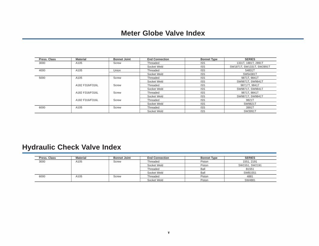
Meter Globe Valve Index
Hydraulic Check Valve Index
Press. Class Material Bonnet Joint End Connection Bonnet Type SERIES3000 A105 Screw Threaded ISS 1331T, 1881T, 2891T
Socket Weld ISS SW1871T, SW1331T, SW2891T4000 A105 Union Threaded ISS 54831T
Socket Weld ISS SW54381T5000 A105 Screw Threaded ISS 9871T, 9841T
Socket Weld ISS SW9871T, SW9841TA182 F316/F316L Screw Threaded ISS 98717T, 9841T
Socket Weld ISS SW9871T, SW9841TA182 F316/F316L Screw Threaded ISS 9871T, 9841T
Socket Weld ISS SW9871T, SW9841TA182 F316/F316L Screw Threaded ISS 9821T
Socket Weld ISS SW9821T6000 A105 Screw Threaded ISS 3991T
Socket Weld ISS SW3991T
Press. Class Material Bonnet Joint End Connection Bonnet Type SERIES3000 A105 Screw Threaded Piston 1551, 2191
Socket Weld Piston SW1551, SW2191Threaded Ball B1551Socket Weld Ball SWB1551
6000 A105 Screw Threaded Piston 4881Socket Weld Piston SW4881

vi
In the late 1890s, Vogt pioneered the early development of ammonia absorption refrigerationsystems that made artificial ice. This business, plus Vogt’s fledgling boiler business created aninternal need for quality valves that initiated Vogt’s early entry into the valve manufacturingbusiness. The early reputation of Vogt’s quality valves and the rapidly growing petroleumprocessing industry created an outside demand that would firmly establish Vogt in the massproduction of high quality forged steel valves.
For more than 100 years, Vogt’s leadership has been evident in the production of forged steelfittings, gate, globe, angle and check valves in most popular materials, trims and bonnetconfigurations.
Today, Vogt Valves supports a worldwide network of distributors with access to the world’slargest capability for the manufacturing of forged steel valves and fittings.
Vogt Valves, Sulphur Springs, TX
Vogt Valves – A History in the Making

1
Page Nos.
Index by Valve Type ............................................................................................ i-vIndex .....................................................................................................................2-3Description of No. System .................................................................................... 4Gate Valves.........................................................................................................5-43Nuclear ...................................................................................................................44Sour Service...........................................................................................................45Globe Valves .................................................................................................... 46-87Check Valves ...................................................................................................89-111Engineering Tables ........................................................................................112-123Fittings & Unions...........................................................................................124-132Spare Parts ..................................................................................................140-143
Abbreviations & Terms Used in the Valve & Fitting Industry, Glossary of............134
ASTM Material Specs. Cross Reference ............................................................117
Auxiliary Operators.................................................................................................88
Care & Maintenance of Vogt Valves .............................................................137-139
Conversions: Weight, Pressure & Temperature ..........................................148-149
Cv Factors ....................................................................................................122-123
Page Nos.
Cv Formulas..................................................................................................120-121
Dimensional Data for Standard & Schedule Pipe ........................................145-146
Materials (Forging) ...............................................................................................118Materials (Valve Trim)...........................................................................................119Materials (General Use) .......................................................................................119
Packaging Data for Fittings .................................................................................126
Pressure-Temperature Service Ratings.........................................................112-115
Replacement Parts...............................................................................................138
Series Number Index ............................................................................................2-3
Standards for Valve & Fitting Industry ..........................................................135-136
Limited Warranty ..................................................................................................133
Thread & Socket Weld Standards........................................................................144
Valve Packing Materials .......................................................................................116
Catalog Sections
PAGE NOS.Check Valves Gate Valves Globe Valves
Alkylation (HF) 93, 97 7, 9, 11, 12, 14, 21 53, 54, 55, 59ASTM A350, Gr. LF2 ( to -50°F) 90-92, 99 6-8, 18, 38, 43 47-49, 55API-600 Wall Thicknesses 94 10, 33, 35, 36 51, 71, 72, 73Extended Body 25-29, 41 62Bellowseal 13, 20, 22, 47-49, 52Chlorine 50, 61Cryogenic (to -325°F) F316, F316L 17 57 Flow Control 63, 64, 76Hydraulic 109-111 83-87(NACE MR-01-75) Sour Service * 45 45 45Nuclear 44 44 44Y-Pattern 107, 108 68, 78, 80-82Zero Leakage 100
* GIobe, Angle and Check Valves can be provided with appropriate trim materials for sour service. Valve series with MB6, MB8 and MBS suffixes meet NACE. See pages 4 and 45 for explanation.
Service Application
Table of Contents

2
S 74..........................96SWS 74 .........................96
229...............126-128SW 229 .......126,127,130
243...............126-128 SW 243 .......126,127,130
259...............126-128273...............126-128
353..........................6BW 353..........................6
353F8M .................6BW 363F8M...................7
353FHF...................6353MB8 ..................6353MM....................6353R .....................20
BW 353R .....................20353T........................6358..........................6363..........................7
BW 363..........................7363FHF...................7363MB8 ..................7363MM ...................7
BW 363MM....................7363R .....................20
BW 363R .....................20368..........................7373 .........................8
BW 373..........................8373F8M...................8
BW 373F8M...................8373FHF...................8373MB8 ..................8373MM....................8
BW 373MM....................8373R .....................20
BW 373R .....................20378..........................8
473........................47473B .....................47473F8M.................47473MB8 ................47473MM..................47483........................48483B .....................48483F8M.................48483MB8 ................48483MM..................48493........................49493B .....................49493F8M.................49493MB8 ................49493MM..................49
SW 503...............126,130573........................90573F8M.................90
573MB8 ................90573MBS................90573MM..................90583........................91583F8M.................91583MB8 ................91583MBS................91583MM..................91593........................92593F8M.................92593MB8 ................92593MBS................92593MM..................92
SW 623...............126,130S 673 .....................95AS 683 .....................95BS 693 .....................95C
701......................100S 701........................95
SW 701......................100SWS 701........................95
701F8M...............100SW 701F8M...............100
701MB8 ..............100SW 701MB8 ..............100
701MBS..............100SW 701MBS..............100
701MM................100SW 701MM................100
701ZLB ...............100701ZLE ...............100701ZLN...............100701ZLV ...............100
B 701........................97SWB 701........................97SWB 701HF6.................97SWB 701HF7 .............. 97
710........................98B 710........................98
SW 710........................98SWB 710........................98
710FHF.................98SW 710FHF.................98
718........................99B 718........................97S 718........................95
SW 718........................99SWB 718........................97SWS 718........................95
718T......................99SW 718T......................99
801........................69SW 801........................69
810........................68SW 810........................68
811 ........................68SW 811 ........................68
822........................68SW 822........................68
851........................70SW 851........................70
1003......................73SW 1003......................73
1023......................73SW 1023......................73
1033......................36SW 1033......................36
1043......................36SW 1043......................36
1160.............126-128SW 1160 ......126,127,130
SWT 1160 ......126,128,1301189.............126-128
1211.............126-128SW 1211 ......126,127,130
SWT 1211 ......126,128,1301260.............126-1281280.............126-1281299.............126,127
SW 1299......126-128,130
1331T....................83SW 1331T....................83
1399.............126-128SW 1399......126,127,130
1510......................78R 1510......................80
SW 1510......................78SWR 1510......................80
1511 ......................78R 1511 ......................80
SW 1511 ......................78SWR 1511 ......................80
1522......................78R 1522......................80
SW 1522......................78SWR 1522......................80
1551....................109B 1551....................109
SW 1551....................109SWB 1551....................109
1610....................107SW 1610....................107
1622....................107SW 1622....................107
1800.............126-1281871T....................83
SW 1871T....................831899.............126,127
SW 1899......126-128,130
1931......126,127,132SW 1931.............126,127
1951......126,127,132SW 1951......126,127,132
1961......126,127,132SW 1961.............126,127
1971......................65SW 1971......................65
2001.............126-128SW 2001......126,127,130
2024.............126,127SW 2024......126-128,130
2090.............126-128SW 2090......126,127,130
2110.............126-128SW 2110 ......126,127,130
2130.............126-1282191 ....................110
SW 2191 ....................1102199.............126-128
SW 2199......126,127,130
2271....................125SW 2271....................125
2324.............126-128SW 2324......126,127,130
2350......126-128,130SW 2350.............126,127
2370.............126-128
2400.............126-1282450.............126-128
SW 2450......126,127,130
2510......................81R 2510......................82
SW 2510......................81SWR 2510......................82
2511 ......................81R 2511 ......................82
SW 2511 ......................81SWR 2511 ......................82
2522......................81R 2522......................82
SW 2522......................81SWR 2522......................82
2560.............126-1282580.............126-128
2610....................108SW 2610....................108
2611 ....................108SW 2611 ....................108
2622....................108SW 2622....................108
2670.............127,128SW 2670....................127
2801......................24
SW 2801......................242801B ...................13
SW 2801B ...................132801F8M...............24
SW 2801F8M...............242801FHF...............24
SW 2801FHF...............242801MB6 ..............24
SW 2801MB6 ..............242801MB8 ..............24
SW 2801MB8 ..............242801MBS..............24
SW 2801MBS..............242801MM................24
SW 2801MM................24TSW 2801......................24TSW 2801FHF...............24
CT 2801......................25SS 2801......................26ST 2801......................26TT 2801......................26ST 2801FHF...............26ST 2801F8M...............26TT 2801F8M...............26SS 2801MB6 ..............26ST 2801MB6 ..............26ST 2801MB8 ..............26ST 2801MM................26TT 2801MM................26
2811 ......................312811FHF ...............31
SW 2811FHF ...............31SW 2811 ......................31
TSW 2811 ......................31TT 2811 ......................26
2821......................67SW 2821......................67
2821FHF...............67SW 2821FHF...............67
2821F8M...............67SW 2821F8M...............67
2831......................30CT 2831......................25ST 2831......................26
2831T....................30TT 2831......................26
2891T....................84SW 2891T....................84BT 2901......................25CT 2901......................25CS 2901......................25BT 2901MB6 ..............25CT 2911 ......................25
3991T....................87SW 3991T....................87
4001.............126-128SW 4001......126,127,130
4200.............126-128SW 4200......126,127,130
4823.............126-128SW 4823......126,127,130
4835......................94SW 4835......................94
4881 ....................111SW 4881 ....................111
5061....................125
6281....................125
9091....................104B 9091....................104
SW 9091....................104SWB 9091....................104
9821T....................86SW 9821T....................86
9841T....................86SW 9841T....................86
9871T....................86SW 9871T....................86
10103....................71SW 10103....................71
10403....................5110603....................7210683....................72
11103 ....................33SW 11103 ....................33
11403 ....................1011603 ....................3511683 ....................35
12111 ....................14BS 12111 ....................27BT 12111 ....................27CT 12111 ....................27ST 12111 ....................28
SW 12111 ....................14TSW 12111 ....................14
TT 12111 ....................2912111ER ...............19
ST 12111ER ...............28SW 12111ER ...............19
12111F8M .............14SW 12111F8M .............14
12111FHF .............14TT 12111FHF .............29
SW 12111FHF .............14SW 12111HF6 .............14SW 12111HF7 .............14
12111MM ..............14SW 12111MM ..............14
12111MB6.............14ST 12111MB6.............28
Series No. Page No. Series No. Page No. Series No. Page No. Series No. Page No. Series No. Page No. Series No. Page No.
Index

3
SW 12111MB6.............14TT 12111MB6.............29
12111MB8.............14BT 12111MB8.............27CT 12111MB8.............27ST 12111MB8.............28
SW 12111MB8.............1412111MBS ............14
SW 12111MBS ............1412111MMT ............14
SW 12111MMT ............1412111R..................22
SW 12111R..................2212111T ..................14
SW 12111T ..................14
12141....................55SW 12141....................55
12141B .................52SW 12141B .................52
12141F8M.............55SW 12141F8M.............55
12141FHF.............55SW 12141HF6.............55SW 12141HF7.............55
12141MB8 ............55SW 12141MB8 ............55
12141T..................55
CT 12141....................62ST 12141....................62TT 12141....................62
SW 12141FHF.............5512141MM..............55
SW 12141MM..............55SW 12141T..................55
12161....................23SW 12161....................23
12161F8M.............23SW 12161F8M.............23
12161MM..............23SW 12161MM..............23
12181....................66SW 12181....................66
12321....................16SW 12321....................16
12321FHF.............16SW 12321FHF.............16
12351....................56SW 12351....................56
12401....................15SW 12401....................15
12401C .................17SW 12401C .................17
12401FHF.............15SW 12401FHF.............15
12401T..................15SW 12401T..................15
12421....................16
SW 12421....................1612421FHF.............16
SW 12421FHF.............1612443....................63
SW 12443....................6312501....................56
SW 12501....................5612501C .................57
SW 12501C .................5712501T..................56
SW 12501T..................5612521....................16
SW 12521....................1612521FHF.............16
SW 12521FHF.............1612551....................56
SW 12551....................56SW 12551FHF.............16
12921....................16SW 12921....................16
12921FHF.............16SW 12921FHF.............16
13111 ....................2113111BB ...............2113111FHF .............2113111F8M .............21
SW 13111 ....................21SW 13111F8M .............21SW 13111FHF .............21SW 13111MB8.............21SW 13111MM ..............21SW 13111HF4 .............21SW 13111HF5 .............21
13111R..................22SW 13111R..................22
13141....................58SW 13141....................58
13141FHF.............58SW 13141FHF.............58
13363MMP .............713373......................913373MMP .............713401....................21
SW 13401....................2113701..................102
SW 13701..................102
15111 ....................37SW 15111 ....................37
15111F8M .............37SW 15111F8M .............37
15111FHF .............37SW 15111FHF .............37
15111MB6.............37SW 15111MB6.............37
15111MB8.............37SW 15111MB8.............37
15111MBS ............37SW 15111MBS ............37
15141....................75SW 15141....................75
15141F8M.............75SW 15141F8M.............75
15141FHF.............75SW 15141FHF.............75
15141MB6 ............75SW 15141MB6 ............75
15141MB8 ............75SW 15141MB8 ............75
15141MBS............75SW 15141MBS............75
15141MM..............75SW 15141MM..............75
15321....................37SW 15321....................37
15351....................75SW 15351....................75
15373....................34RJ 15373....................34
15373FHF.............34RJ 15373FHF.............34
15401....................37SW 15401....................37
15443....................76SW 15443....................76
15493....................7415493F8M.............7415493FHF.............7415493MB6 ............7415493MB8 ............7415493MBS............7415493MM..............74
15501....................75SW 15501....................75
15501FHF.............75SW 15501FHF.............75
15593..................105SW 15593..................105
15593FHF...........105SW 15593FHF...........105
15701..................106B 15701..................106
SW 15701..................106SWB 15701..................106
15701FHF...........106SW 15701FHF...........106
15801....................40ST 15801....................41
SW 15801....................40ST 15801F8M.............41
15801FHF.............40SW 15801FHF.............40
15801MB8 ............40SW 15801MB8 ............40
15801MBS............40
SW 15801MBS............4015801MM..............40
SW 15801MM..............4015821....................77
SW 15821....................7715821F8M.............77
SW 15821F8M.............7715821FHF.............77
SW 15821FHF.............7715821MB6 ............77
SW 15821MB6 ............7715821MB8 ............77
SW 15821MB8 ............7715821MBS............77
SW 15821MBS............7715821MM..............77
SW 15821MM..............7715831....................40
SW 15831....................40
16111 ....................39SW 16111 ....................39
22141CL ...............61SW 22141CL ...............61
22141F8M.............60SW 22141F8M.............60
22141MM..............60SW 22141MM..............60
22141MT...............61SW 22141MT...............61
22461....................64SW 22461....................64
22461FHF.............64SW 22461FHF.............64
22483CL ...............5022493CL ...............5022493MT...............50
SW 23141HF4.............59SW 23141HF5.............59
32111 ..............18, 4332111F8M.......18, 4332111MB8.......18, 4332111MM ..............18
SW 32111 ..............18, 43TSW 32111 ....................18
SW 32111F8M.......18, 43TSW 32111F8M .............18
SW 32111MB8.......18, 43SW 32111MM ..............18
32141....................55SW 32141....................55
32141F8M.............55SW 32141F8M.............55
32141MB8 ............55SW 32141MB8 ............55
32353......................632353MB8 ..............632363......................732363MB8 ..............732373......................832373MB8 ..............832473....................4732483....................4832493....................4932573....................9032583....................9132593....................92
32701....................99SW 32701....................99
32701MB8 ............99SW 32701MB8 ............99
35111 ..............38, 43SW 35111 ..............38, 43
35111F8M.......38, 43SW 35111F8M.......38, 43
35111MB8.......38, 43SW 35111MB8.......38, 43
41000 04...............1941000 06...............1941000 08...............1941000 09...............19
42211MTG ............11SW 42211MTG ............11SW 42241HF2.............54
42241MTG............54SW 42241MTG............54
43111MMP............12SW 43211HF2 .............11
43241MMP ...........5343241MTP ............53
SWB 43721HF2.............93SWB 43721HF4.............93SWB 43721HF5.............93
54853..................103SW 54853..................103
54863..................10358431T..................85
SW 58431T..................85
59851....................32SW 59851....................32
59851F8M.............32SW 59851F8M.............32
59851MBS............32SW 59851MBS............32
59851MM..............32SW 59851MM..............32
59951....................3259951T..................32
66703....................42SW 66703....................42
66713....................42SW 66713....................42
66723....................79SW 66723....................79
66733....................79SW 66733....................79
66773....................42SW 66773....................42
66793....................79SW 66793....................79
82401....................15SW 82401....................15
82401FHF.............15
82501....................56SW 82501....................56
82718....................99SW 82718....................99
Series No. Page No. Series No. Page No. Series No. Page No. Series No. Page No. Series No. Page No. Series No. Page No.

SW 12111 F8M
Series Number(typical)
Prefix:This maximum 3 alphameric letter beginning the Vogt Valve seriesnumber is normally indicative of the valve connection. Historically, a fewdesign features have also been used as part of the prefix including S, Band R. A fully female threaded valve as the traditional Vogt standarddoes not have a prefix number (see below for prefix descriptions).
Suffix:This maximum 3 alphameric character ending of the Vogt Valveseries number is normally indicative of the valve internal trimpackage. Historically, packing and a few design features have alsobeen used as part of the suffix number including T, B and ER. Avalve with the traditional Vogt standard trim package and packingis not assigned a suffix number (see below for suffix descriptions).
Prefix Description:(Blank) - Female NPT (both ends)B - Ball Check (female NPT)BS - Female SW by Male Butt WeldBT - Female Thd by Male Butt WeldBW - Butt WeldCS - Female SW by Male Couplet CT - Female Thd by Male Couplet R - In-Line Repair (female NPT)RJ - Ring Joint Flanges S - Swing Check (female NPT)SS - Female SW by Male SW ST - Female Thd by Male SW SW - Socket Weld SWB - Ball Check (SW) SWR - In-line Repairable (SW) SWS - Swing Check (SW) TS - Female SW by Male Thd TSW - Female Thd by Female SW TT - Female Thd by Male Thd
Suffix Description:(Blank) – Standard TrimB – Bellows Valve C – Cryogenic Valve CL – Chlorine Valve Trim – Monel/Hastelloy ER – Emissions Reduction – Double Packed with Lantern Ring F8M– 316 TrimFHF – Full Hard Face (unless standard) FH8 – Full Hard Faced F8M TrimFHT – Teflon Packing and Full Hard FaceHF – Hard Faced Disc (F316 Globes and Checks Only) HF2 – UOP Alkylation HF4 – UOP Alkylation HF5 – UOP Alkylation HF6 – UOP Alkylation HF7 – UOP Alkylation L – Locking Device MB6 – 13% Chrome Trim – NACE MB8 – 316 Trim Hard Faced Seats and Disc/Wedge – NACE MBS – Monel Trim – NACE MM – Monel Trim – Grafoil Packing and Gasket MMP – Phillips Alkylation MMT – Monel Trim – Teflon Packing and Gasket MT – Chlorine Valve Trim – Monel/Teflon Disc/HastelloyMTG – Vogt Alkylation MTP – Phillips Alkylation R– Reactive Seal T – Teflon Packing and Gasket ZLB – Zero Leakage Check Valve – Buna N ZLE – Zero Leakage Check Valve – Ethylene Propylene ZLN – Zero Leakage Check Valve – Neoprene ZLV – Zero Leakage Check Valve – Viton 14
Valve Design/Material:This maximum 5 numeric character uniquelyidentifies the valve to its design (gate, globe,angle, check, etc.) and pressure boundary materialof construction (A105, A182-F5, F11, F316, etc.).The prefix and suffix to this number provide detailsto the design, end connections and trim optionincluding packing.
Legend:The prefixes and suffixes based ondesign are limited to S, B, R and ER (as listed above) ONLY.
Expansion of new valve designs areadded as new SERIES NUMBERS.
(See the VV 200 individual pages forstandard series available.)
Description of Series Number System for Vogt Valves(Order Vogt Valves & Fittings by size—series number)
4

89
Check Valve Section – Pages 89-111
Vogt check valves are forged from
fine grain steel and are available
with threaded, socket weld or
flanged ends. Most bonnet designs,
including bolted, seal weld, union,
and bonnetless type check valves
are manufactured to meet a wide
variety of service applications.
Piston, ball, swing and spring
controlled check valve designs for
horizontal or vertical (upward) flow
applications for the most often
specified pressure classes are
available. A spring can be added to
piston check valves not currently
equipped with that option if specified
on the order.
Vogt’s “Y” pattern check valves
complement our “Y” pattern and In-
Line repairable globe valve lines
used in refineries, chemicals, power
and related industries.
Piston and ball check valves should
not be used in applications where
rusting or rust particles are present
or anticipated. Swing check valves
are more tolerant for applications of
this nature.
Vogt check valves (non spring loaded) should be sized
to provide a minimum of 2 psi pressure drop for ball and
piston type valves and 1/2 psi for swing check type
valves. This will assure that the valves will not be subject
to noisy operation and premature wear of parts.
Spring loaded piston check valves are the Vogt
preference for reciprocating compressor service in
which a history of noisy check valve operation has
been experienced.
Check valves are designed to prevent reverse flow.
Leakage rate for Vogt check valves with metal-to-metal
seats are dependent on the amount of back pressure
and the viscosity of the flowing medium. Check valves
should not be used in gas or low back pressure liquid
applications if zero leakage is desired. See Page 100 for
Vogt zero leakage check valves.
BOLTED BONNETPISTON CHECK VALVE
NO BONNETSWING CHECK VALVE
BOLTED BONNETBALL CHECK VALVE
Dimensions are in inches and millimeters.
Dimensions are subject to change without notice.
Order by Size and Series Number.

90
Forged Check Valves
CH
EC
KC
LA
SS
150
(P
N 2
0)57
3, 3
2573
Flanged Ends 1/16" R.F.
Size
A-End-to-End
B
C
D-Seat Diameter
Weight
3/4
20
4.62
117
2.56
65
3.88
99
.50
12.5
6.5
3.0
1/2
15
4.25
108
2.56
65
3.50
89
.50
12.7
5.3
2.4
Dimensions
Valve flanges conform to ASME Standard B16.5 and end-to-enddimensions conform to ASME Standard B16.10.
For Cv factors see page 123, Valve Matrix FF.Refer to pages 116-120 for full materials description.
1
25
5.00
127
3.12
79
4.25
108
.75
19.1
10.1
4.6
1-1/2
40
6.50
165
4.50
114
5.00
127
1.28
32.5
20.7
9.4
2
50
8.00
203
4.94
125
6.00
152
1.53
38.9
33.1
15.0
NPS
DN
MATERIALS MEETREQUIREMENTS OF
NACE STANDARD MR-01-75 FOR
SOUR SERVICE
■ Round Bolted Bonnet■ Spiral Wound Gasket■ Horizontal Type■ Piston Check■ Integral Hard Faced Seat■ ASME B16.34
Class 150 (PN 20)Conventional Port285 PSI @ 100°F (19.7 BAR @ 38°C)For other ratings see pgs. 112-115
Body/Bonnet SERIES NUMBER
A105 573 Trim: 13% Cr. Seat: HF
573MB8 Trim: 316 SSDisc/Seat: HF
573MBS Trim: MonelSeat: HF
573MM Trim: MonelSeat: HF
573F8M Trim: 316 Seat: HF
A350 LF2 32573 Trim: 13% Cr. Seat: HF
Meets API-602 required wallthicknesses.
Bold face numerals are in inches and pounds.Blue numerals are in millimeters and kilograms.

91
Forged Check Valves
CH
EC
KC
LA
SS
300
(P
N 5
0)58
3, 3
2583
Flanged Ends 1/16" R.F.
Bold face numerals are in inches and pounds.Blue numerals are in millimeters and kilograms.
Valve flanges conform to ASME Standard B16.5 and end-to-enddimensions conform to ASME Standard B16.10.
For Cv factors see page 123, Valve Matrix FF.Refer to pages 116-120 for full materials description.
3/4
20
7.00
178
2.56
65
4.62
117
.50
12.7
10.0
4.5
1
25
8.00
203
3.12
79
4.88
124
.75
19.1
13.7
6.2
NPS
DN
1-1/2
40
9.00
229
4.50
114
6.12
155
1.28
32.5
27.9
12.7
2
50
10.50
267
4.94
125
6.50
165
1.53
38.9
38.0
17.3
1/2
15
6.00
152
2.56
65
3.75
95
.50
12.7
6.6
3.0
Size
A-End-to-End
B
C
D-Seat Diameter
Weight
■ Round Bolted Bonnet■ Spiral Wound Gasket■ Horizontal Type■ Piston Check■ Integral Hard Faced Seat■ ASME B16.34
Dimensions
Class 300 (PN 50)Conventional Port740 PSI @ 100°F (51.0 BAR @ 38°C)For other ratings see pgs. 112-115
Body/Bonnet SERIES NUMBER
A105 583 Trim: 13% Cr. Seat: HF
583MB8 Trim: 316 SSDisc/Seat: HF
583MBS Trim: MonelSeat: HF
583MM Trim: MonelSeat: HF
583F8M Trim: 316 Seat: HF
A350 LF2 32583 Trim: 13% Cr. Seat: HF
Meets API-602 required wall thicknesses.
MATERIALS MEETREQUIREMENTS OF
NACE STANDARD MR-01-75 FOR
SOUR SERVICE

92
Forged Check Valves
CH
EC
KC
LA
SS
600
(P
N 1
10)
593,
325
93
2
50
11.50
292
4.94
125
6.50
165
1.53
38.9
41.8
19.0
Dimensions
Valve flanges conform to ASME Standard B16.5 and end-to-enddimensions conform to ASME Standard B16.10.
For Cv factors see page 123, Valve Matrix FF.Refer to pages 116-120 for full materials description.
Size
A-End-to-End
B
C
D-Seat Diameter
Weight
1/2
15
6.50
165
2.56
65
3.75
95
.50
12.7
6.9
3.1
3/4
20
7.50
190
2.56
65
4.62
117
.50
12.7
9.8
4.4
1
25
8.50
216
3.12
79
4.88
124
.75
19.1
15.2
6.9
1-1/2
40
9.50
241
4.50
114
6.12
155
1.28
32.5
31.2
14.2
NPS
DN
MATERIALS MEETREQUIREMENTS OF
NACE STANDARD MR-01-75 FOR
SOUR SERVICE
Bold face numerals are in inches and pounds.Blue numerals are in millimeters and kilograms.
Flanged Ends 1/4" R.F.
■ Round Bolted Bonnet■ Spiral Wound Gasket■ Horizontal Type■ Piston Check■ Integral Hard Faced Seat■ ASME B16.34
Class 600 (PN 110)Conventional Port1480 PSI @ 100°F (102.1 BAR @ 38°C)For other ratings see pgs. 112-115
Body/Bonnet SERIES NUMBER
A105 593 Trim: 13% Cr. Seat: HF
593MB8 Trim: 316 SSDisc/Seat: HF
593MBS Trim: MonelSeat: HF
593MM Trim: MonelSeat: HF
593F8M Trim: 316 Seat: HF
A350 LF2 32593 Trim: 13% Cr.Seat: HF
Meets API-602 required wall thicknesses.

93
Forged Check Valves – For HF Alkylation Service
CH
EC
KC
LA
SS
800
(P
N 1
30)
B 4
3721
■ Round Bolted Bonnet■ Spiral Wound Gasket■ Horizontal Type■ Ball Check■ Removable Seat■ ASME B16.34
Dimensions
Refer to pages 116-120 for full materials description.
Size
A-End-to-End
B
C
D-Seat Diameter
Weight
1/2
15
4.00
102
1.12
28
2.56
65
.39
9.9
3.5
1.6
3/4
20
4.62
117
1.56
40
3.06
78
.59
15.0
6.5
3.0
1
25
6.25
159
2.25
57
4.50
114
.97
24.6
17.5
8.0
1-1/2
40
7.75
197
2.69
68
4.88
124
1.44
36.6
25.8
11.7
2
50
9.00
229
3.50
89
5.94
151
1.88
47.8
47.4
21.5
NPS
DN
HYDROFLURICACID (HF)
ALKYLATION VALVES.UOPAPPROVED.
Bold face numerals are in inches and pounds.Blue numerals are in millimeters and kilograms.
For Cv factors see page 123, Valve Matrix HH.
Class 800 (PN 130)1975 PSI @ 100°F (136.2 BAR @ 38°C)For other ratings see pgs. 112-115
A105 Body/Bonnet
SERIES NUMBER
Threaded Socket Weld– SWB43721HF2 Sizes 1/2-1”
Trim: Monel
– SWB43721HF4 Trim: Monel
– SWB43721HF5Trim: Monel

94
Forged Check Valves
SW
ING
CH
EC
KC
LA
SS
800
(P
N 1
30)
4835
■ Round Bolted Bonnet■ Flat Gasket Joint■ Horizontal or Vertical Upward Flow■ Swing Check■ Renewable Seat■ ASME B16.34
Class 800 (PN 130)Conventional Port1975 PSI @ 100°F (136.2 BAR @ 38°C)For other ratings see pgs. 112-115
A105 Body/Bonnet
SERIES NUMBER
Threaded Socket Weld4835 SW4835
Trim: 13% Cr.
Meets API-600 required wall thicknesses.
1/2
15
4.00
102
1.31
33
4.62
117
.39
9.9
13.2
6.0
Dimensions
Refer to pages 116-120 for full materials description. For Cv factors see page 123, Valve Matrix JJ.
Size
A-End-to-End
B
C
D-Seat Diameter
Weight
3/4
20
4.00
102
1.31
33
4.62
117
.39
9.9
13.0
6.0
1
25
5.00
127
1.75
44
5.50
140
.69
17.5
22.1
10.0
1-1/4
32
6.50
165
2.19
56
6.38
162
.97
24.6
29.1
13.2
1-1/2
40
6.50
165
2.19
56
6.38
162
1.19
30.2
30.2
13.7
2
50
7.25
184
2.62
66
6.94
176
1.44
36.6
39.9
18.1
NPS
DN
Bold face numerals are in inches and pounds.Blue numerals are in millimeters and kilograms.

95
Forged Check Valves
CH
EC
KC
LA
SS
800
(P
N 1
30)
S 7
01, S
718
■ Round Bolted Bonnet■ Spiral Wound Gasket■ Horizontal or Vertical Upward Flow■ Swing Check■ Hard Faced Seat■ ASME B16.34
Class 800 (PN 130)Conventional Port1975 PSI @ 100°F (136.2 BAR @ 38°C)For other ratings see pgs. 112-115
A105 Body/Bonnet
SERIES NUMBER
Threaded Socket WeldS701 SWS701
Trim: 13% Cr.Seat: HF
F316, F316L Body/Bonnet1920 PSI @ 100°F (132.4 BAR @ 38°C)
S718 SWS718Trim: 316Seat: HF
Dimensions
Refer to pages 116-120 for full materials description. For Cv factors see page 123, Valve Matrix MM.
Size
A-End-to-End
B
C
D-Seat Diameter
Weight
1/2
15
3.38
86
.78
20
2.33
59
.50
12.7
3.9
1.8
3/4
20
3.38
86
.78
20
2.33
59
.50
12.7
3.8
1.7
1
25
4.19
106
.97
25
3.06
78
.75
19.1
6.1
2.7
1-1/2
40
5.44
138
1.28
33
4.46
113
1.25
31.8
16.5
7.5
2
50
5.94
151
1.56
40
4.92
125
1.50
38.1
25.3
11.5
NPS
DN
Bold face numerals are in inches and pounds.Blue numerals are in millimeters and kilograms.

Forged Check Valves
CH
EC
KC
LA
SS
150
(P
N 2
0)S
673
■ Round Bolted Bonnet■ Spiral Wound Gasket■ Horizontal or Vertical Upward Flow■ Swing Check■ Hard Faced Seat■ ASME B16.34
Class 150 (PN 20)Conventional Port285 PSI @ 100°F (19.7 BAR @ 38°C)For other ratings see pgs. 112-115
A105 Body/Bonnet
SERIES NUMBER
S673 Trim: 13% Cr.Seat: HF
Dimensions
Refer to pages 116-120 for full materials description. For Cv factors see page 123, Valve Matrix MM.
Size
A-End-to-End
B
C
D-Seat Diameter
Weight
1/2
15
4.25
108
2.33
59
3.50
89
.50
12.7
4.8
2.2
3/4
20
4.62
117
2.33
59
3.88
99
.50
12.7
6.2
2.8
1
25
5.00
127
3.06
78
4.25
108
.75
19.1
9.1
4.1
1-1/2
40
6.50
165
4.43
112
5.00
127
1.25
31.8
18.8
8.5
2
50
8.00
203
4.89
124
6.00
152
1.50
38.1
33.2
15.1
NPS
DN
Bold face numerals are in inches and pounds.Blue numerals are in millimeters and kilograms.
Flanged Ends 1/16" R.F.
95A
Forged Check Valves
CH
EC
KC
LA
SS
300
(P
N 5
0)S
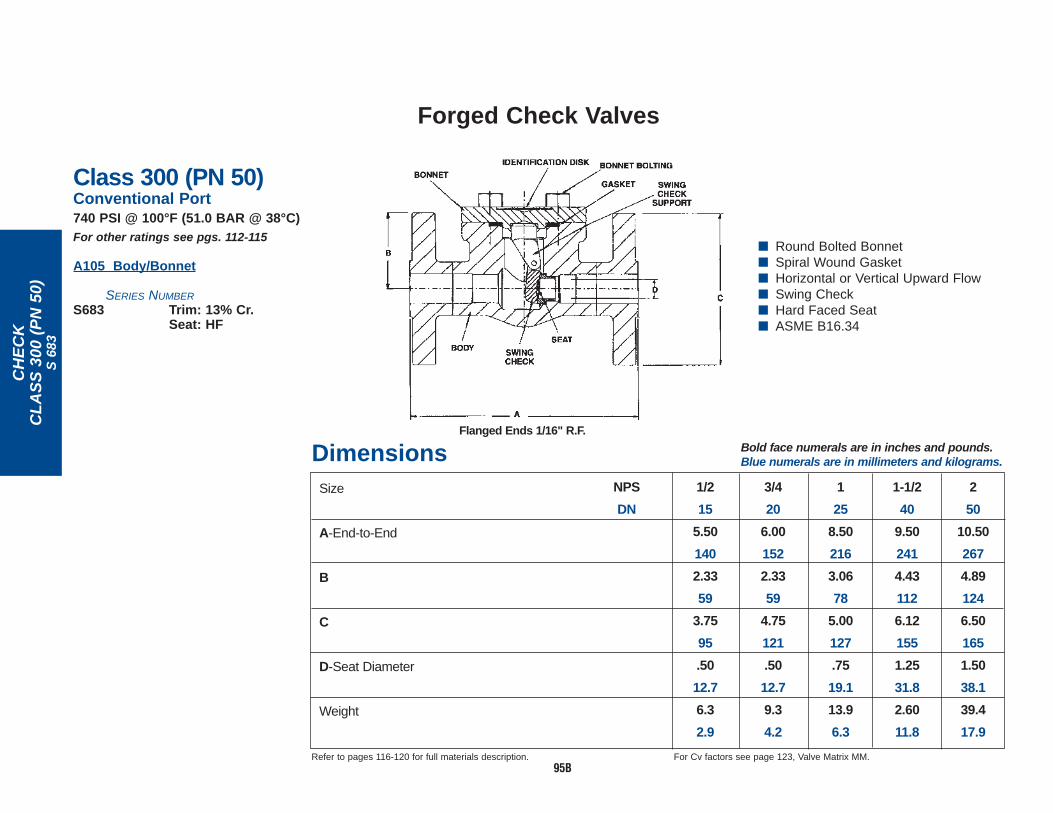
683
■ Round Bolted Bonnet■ Spiral Wound Gasket■ Horizontal or Vertical Upward Flow■ Swing Check■ Hard Faced Seat■ ASME B16.34
Class 300 (PN 50)Conventional Port740 PSI @ 100°F (51.0 BAR @ 38°C)For other ratings see pgs. 112-115
A105 Body/Bonnet
SERIES NUMBER
S683 Trim: 13% Cr.Seat: HF
Dimensions
Refer to pages 116-120 for full materials description. For Cv factors see page 123, Valve Matrix MM.
Size
A-End-to-End
B
C
D-Seat Diameter
Weight
1/2
15
5.50
140
2.33
59
3.75
95
.50
12.7
6.3
2.9
3/4
20
6.00
152
2.33
59
4.75
121
.50
12.7
9.3
4.2
1
25
8.50
216
3.06
78
5.00
127
.75
19.1
13.9
6.3
1-1/2
40
9.50
241
4.43
112
6.12
155
1.25
31.8
2.60
11.8
2
50
10.50
267
4.89
124
6.50
165
1.50
38.1
39.4
17.9
NPS
DN
Bold face numerals are in inches and pounds.Blue numerals are in millimeters and kilograms.
Flanged Ends 1/16" R.F.
95B

95C
Forged Check Valves
CH
EC
KC
LA
SS
600
(P
N 1
10)
S 6
93
■ Round Bolted Bonnet■ Spiral Wound Gasket■ Horizontal or Vertical Upward Flow■ Swing Check■ Hard Faced Seat■ ASME B16.34
Class 600 (PN 110)Conventional Port1480 PSI @ 100°F (102.1 BAR @ 38°C)For other ratings see pgs. 112-115
A105 Body/Bonnet
SERIES NUMBER
S693 Trim: 13% Cr.Seat: HF
Dimensions
Refer to pages 116-120 for full materials description. For Cv factors see page 123, Valve Matrix MM.
Size
A-End-to-End
B
C
D-Seat Diameter
Weight
1/2
15
6.50
165
2.33
59
3.75
95
.50
12.7
6.9
3.1
3/4
20
7.50
190
2.33
59
4.62
117
.50
12.7
10.2
4.6
1
25
8.50
216
3.06
78
5.00
127
.75
19.1
14.4
6.5
1-1/2
40
9.50
241
4.43
112
6.12
155
1.25
31.8
27.8
12.6
2
50
11.50
292
4.89
124
6.50
165
1.50
38.1
43.2
19.6
NPS
DN
Bold face numerals are in inches and pounds.Blue numerals are in millimeters and kilograms.
Flanged Ends 1/4" R.F.

96
Forged Check Valves
SW
ING
CH
EC
KC
LA
SS
800
(P
N 1
30)
S 7
4
■ No Bonnet■ Horizontal or Vertical Upward Flow■ Swing Type Check■ Welded Seat Insert with Integral
Stainless Seat Deposit■ ASME B16.34
Class 800 (PN 130)Conventional Port1975 PSI @ 100°F (136.2 BAR @ 38°C)For other ratings see pgs. 112-115
A105 Body/Bonnet
SERIES NUMBER
Threaded Socket WeldS74 SWS74
Trim: 13% Cr. with Type 309Integral Seat
Dimensions
Refer to pages 116-120 for full materials description. For Cv factors see page 123, Valve Matrix MM.
Size
A-End-to-End
B
C-Seat Diameter
Weight
1/2
15
3.50
89
1.75
44
.50
12.7
3.7
1.5
3/4
20
3.50
89
1.75
44
.50
12.7
3.6
1.6
1
25
4.00
102
2.00
51
.75
19.1
5.1
2.3
1-1/2
40
5.00
127
2.50
64
1.25
31.8
10.7
4.9
2
50
6.75
171
3.38
86
1.50
38.1
23.7
10.8
NPS
DN
Bold face numerals are in inches and pounds.Blue numerals are in millimeters and kilograms.

97
Forged Check Valves
CH
EC
KC
LA
SS
800
(P
N 1
30)
B 7
01, B
718
Dimensions
Refer to pages 116-120 for full materials description. For Cv factors see page 123, Valve Matrix FF.
Size
A-End-to-End
B
C
D-Seat Diameter
Weight
3/4
20
4.00
102
1.12
28
2.56
65
.50
12.7
3.5
1.5
1
25
4.62
117
1.56
40
3.06
78
.75
19.1
6.2
2.8
1-1/4
32
6.25
159
2.25
57
4.50
114
1.28
32.5
17.6
8.0
1-1/2
40
6.25
159
2.25
57
4.50
114
1.28
32.5
17.0
7.7
2
50
7.75
197
2.69
68
4.94
125
1.53
38.9
26.1
11.8
NPS
DN
1/2
15
3.75
95
1.00
25
2.56
65
.50
12.7
3.4
1.5
■ Round Bolted Bonnet■ Spiral Wound Gasket■ Horizontal Type■ Ball Check■ Integral Seat■ ASME B16.34
Class 800 (PN 130)Conventional Port1975 PSI @ 100°F (136.2 BAR @ 38°C)For other ratings see pgs. 112-115
A105 Body/Bonnet
SERIES NUMBER
Threaded Socket WeldB701 SWB701
Trim: 18% Cr. Seat: HF
– SWB701HF6 Sizes 1/2-2 (No 1-1/4)– SWB701HF7 Sizes 1/2-2 (No 1-1/4)
Trim: 18% Cr. Seat: HF
316/316L Body/Bonnet1920 PSI @ 100°F (132.4 BAR @ 38°C)
B718 SWB718Trim: 316
HYDROFLUORICACID (HF
ALKYLATION VALVES.UOPAPPROVED.
Bold face numerals are in inches and pounds.Blue numerals are in millimeters and kilograms.

98
Forged Check Valves – Spring Control
CH
EC
KC
LA
SS
800
(P
N 1
30)
710
■ Round Bolted Bonnet■ Spiral Wound Gasket■ Horizontal or Vertical Upward Flow■ Spring Control■ Piston Check or Ball Check■ Integral Hard Faced Seat■ ASME B16.34
Class 800 (PN 130)Conventional Port1975 PSI @ 100°F (136.2 BAR @ 38°C)For other ratings see pgs. 112-115
A105 Body/Bonnet
SERIES NUMBERThreaded Socket Weld710 SW 710
Trim: 13% Cr. (302 Spring)Seat: HF
710FHF SW710FHFTrim: 13% Cr. (302 Spring)Disc/Seat: HF
A105 Body/Bonnet
SERIES NUMBER
Threaded Socket WeldB 710 SWB 710
Trim: 18% Cr. (302 Spring)Seat: HF
Dimensions Bold face numerals are in inches and pounds.Blue numerals are in millimeters and kilograms.
1/48
3.7595
1.0025
2.5665.5012.73.41.5
3/810
3.7595
1.0025
2.5665.5012.73.41.5
1-1/240
6.251592.2557
4.501141.2832.516.57.5
Refer to pages 116-120 for full materials description.
Size
A-End-to-End
B-Center-to-Bottom
C-Center-to-Top
D-Seat Diameter
Weight
1/215
3.7595
1.0025
2.5665.5012.73.21.5
3/420
4.001021.1228
2.5665.5012.73.41.5
125
4.621171.5640
3.0678.7519.16.12.8
250
7.751972.6968
4.941261.5338.925.011.4
NPSDN
1-1/432
6.251592.2557
4.501141.2832.517.07.7
Dimensions Bold face numerals are in inches and pounds.Blue numerals are in millimeters and kilograms.
1/215
3.7595
1.0025
2.5665.5012.73.21.5
3/420
4.001021.1228
2.5665.5012.73.41.5
Size
A-End-to-End
B-Center-to-Bottom
C-Center-to-Top
D-Seat Diameter
Weight
125
4.621171.5640
3.0678.7519.16.12.8
1-1/240
6.251592.2557
4.501141.2832.516.57.5
250
7.751972.6968
4.941261.5338.925.011.4
NPSDN

99
Forged Check Valves
CH
EC
KC
LA
SS
800
(P
N 1
30)
3270
1, 7
18, 8
2718
MATERIALS MEETREQUIREMENTS OF
NACE STANDARD MR-01-75 FOR
SOUR SERVICE
Dimensions
See next page for assistance in selecting the type of "ZL" Ring to use. +Valves contain TEFLON — maximum temperature 500°F.Refer to pages 116-120 for full materials description.
For Cv factors see page 123, Valve Matrix FF.
1/4
8
3.75
95
1.00
25
2.56
65
.50
12.7
3.4
1.5
1/2
15
3.75
95
1.00
25
2.56
65
.50
12.7
3.2
1.5
3/4
20
4.00
102
1.12
28
2.56
65
.50
12.7
3.4
1.5
1
25
4.62
117
1.56
40
3.06
78
.75
19.1
6.1
2.8
1-1/2
40
6.25
159
2.25
57
4.50
114
1.28
32.5
16.5
7.5
2
50
7.75
197
2.69
68
4.94
125
1.53
38.9
25.0
11.4
NPS
DN
1-1/4
32
6.25
159
2.25
57
4.50
114
1.28
32.5
17.0
7.7
■ Round Bolted Bonnet■ Spiral Wound Gasket■ Horizontal Type■ Piston Check■ Integral Hard Faced Seat■ ASME B16.34
3/8
10
3.75
95
1.00
25
2.56
65
.50
12.7
3.4
1.5
Bold face numerals are in inches and pounds.Blue numerals are in millimeters and kilograms.
Size
A-End-to-End
B
C
D-Seat Diameter
Weight
Class 800 (PN 130)Conventional PortFor other ratings see pgs. 112-115
A350 LF2 Body/Bonnet1975 PSI @ 100°F (136.2 BAR @ 38°C)
SERIES NUMBER
Threaded Socket Weld32701 SW32701
Trim: 13% Cr. Seat: HF
32701MB8 SW32701MB8Trim: 316SSDisc/Seat: HF
F316/F316L Body/Bonnet1920 PSI @ 100°F (132.4 BAR @ 38°C)
Threaded Socket Weld718 SW718 Sizes 1/2-2 (no 1 1/4)718T+ SW718T+
Trim: 316
F316H Body/Bonnet1920 PSI @ 100°F (132.4 BAR @ 38°C)
Threaded Socket Weld82718 SW82718
Trim: 316H

100
Forged Check Valves
CH
EC
KC
LA
SS
800
(P
N 1
30)
701
Dimensions
See preceding page for assistance in selecting the type of "ZL" Ring to use.Refer to pages 116-120 for full materials description.
For Cv factors see page 123, Valve Matrix FF.
3/8
10
3.75
95
1.00
25
2.56
65
.50
12.7
3.4
1.5
1/4
8
3.75
95
1.00
25
2.56
65
.50
12.7
3.4
1.5
Size
A-End-to-End
B
C
D-Seat Diameter
Weight
1/2
15
3.75
95
1.00
25
2.56
65
.50
12.7
3.2
1.5
3/4
20
4.00
102
1.12
28
2.56
65
.50
12.7
3.4
1.5
1
25
4.62
117
1.56
40
3.06
78
.75
19.1
6.1
2.8
1-1/2
40
6.25
159
2.25
57
4.50
114
1.28
32.5
16.5
7.5
2
50
7.75
197
2.69
68
4.94
125
1.53
38.9
25.0
11.4
NPS
DN
1-1/4
32
6.25
159
2.25
57
4.50
114
1.28
32.5
17.0
7.7
■ Round Bolted Bonnet■ Spiral Wound Gasket■ Horizontal Type■ Piston Check■ Integral Hard Faced Seat■ ASME B16.34
Soft Insert "ZL" RingZero Leakage
Trim: 13% CrSeat: HF}
MATERIALS MEETREQUIREMENTS OF
NACE STANDARD MR-01-75 FOR
SOUR SERVICE
Bold face numerals are in inches and pounds.Blue numerals are in millimeters and kilograms.
Class 800 (PN 130)Conventional PortFor other ratings see pgs. 112-115
A105 Body/Bonnet1975 PSI @ 100°F (136.2 BAR @ 38°C)
SERIES NUMBER
Threaded Socket Weld701 SW701
Trim: 13% Cr. Seat: HF
701F8M SW701F8M 1/2-2 (no 1 1/4)Trim: 316Seat: HF
701MM SW701MM 1/2-2 (no 1 1/4)Trim: MonelSeat: HF
701MB8 SW701MB8Trim: 316Disc/Seat: HF
701MBS SW701MBSTrim: MonelSeat: HF
ZERO LEAKAGE "ZL" (RING)701ZLB Buna N-20°F to 250°F
701ZLE Ethylene-20°F to 300°F Propylene
701ZLN Neoprene-20°F to 240°F
701ZLV Viton-20°F to 400°F

101
BUNA
NVI
TON
ETHY
LENE
PRO
POLY
ENE
(EPR
)NE
OPR
ENE
Compound Selection Guide*for Service Fluids Commonly Used in Vogt “ZL” Check Valves
Acetone ●
Acetylene ● ● ●
Air ● ● ● ●
Alcohols ● ●
Amines—Mixed ● ●
Ammonia (Anhydrous) ● ●
Ammonia (Aqueous) ● ●
Ammonium Phosphate ● ● ●
Asphalt ●
Barium Carbonate ● ● ●
Beet Sugar Liquors ● ● ●
Benzene (Beneol) ●
Butane ● ● ●
Cane Sugar Liquors ● ● ● ●
Carbon Bisulfide ●
Castor Oil ● ● ●
Caustic Soda ● ● ● ●
Crude Oil ● ●
Diesel Oils ● ●
Dowtherms ●
Ethyl Alcohol ● ● ●
Ethyl Chloride (Dry) ● ●
Ethylene Glycol ● ● ● ●
Fish Oils ●
Freon 12, 13, 22 ●
Fuel Oil ● ●
Furfural ●
Gas, Manufactured ●
Gas, Natural ● ● ●
Gasoline, Leaded ● ●
Gasoline, Refined ● ●
Gasoline, Sour ● ●
Gasoline, Unleaded ● ●
Glucose ● ● ● ●
Glue ● ● ●
Glycerin ● ● ● ●
Hydraulic Oil ● ●
Hydrocarbons ● ●
Hydrogen Gas (Cold) ● ● ● ●
Hydrogen Sulfide (Dry) ●
Jet Fuel ● ●
Kerosene ● ●
Linseed Oil ● ●
Lubricating Oil ● ●
Magnesium Hydroxide ● ● ● ●
Magnesium Hydrox. (Hot) ● ● ● ●
Magnesium Sulfate ● ● ● ●
Maleic Acid ●
Mercury ● ● ● ●
Methane ● ●
Methyl Alcohol ● ● ●
Mineral Oil ● ●
Mustard ●
Naphtha ●
Naphthalene ●
Natural Gas ● ● ●
Nitrogen ● ● ● ●
Oils, Animal ● ●
Oils, Fuel ● ●
Oils, Mineral ● ●
Oils, Petroleum (Refined) ● ●
Oils, Petroleum (Sour) ● ●
Oxygen (Cold) ● ● ●
Palmitic Acid ● ●
Pentane ● ●
Potassium Carbonate ● ● ●
Potassium Cyanide ● ● ● ●
Potassium Hydroxide ● ●
Potassium Nitrate ● ● ● ●
Potassium Permanganate ● ●
Potassium Phosphate ● ● ●
Potassium Sulfate ● ● ● ●
Potassium Sulfide ● ● ●
Potassium Sulfite ● ● ● ●
Propane ● ●
Pyrogallic Acid ●
Shellac (Bleached) ●
Shellac (Orange) ●
Soap Solutions (Stearates) ● ● ●
Sodium Carbonate ● ● ● ●
Sodium Chromate ● ●
Sodium Cyanide ● ● ●
Sodium Hydroxide ● ● ● ●
Sodium Metaphosphate ● ● ●
Sodium Nitrate ●
Sodium Perborate ● ●
Sodium Silicate ● ● ● ●
Sodium Sulfate ● ● ● ●
Sodium Sulfide ● ● ● ●
Sodium Sulfite ● ● ● ●
Sodium Thiosulfate (Hypo) ● ● ● ●
Steam (212° F) ●
Sulfur Dioxide (Dry) ●
Tar & Tar Oil ●
Toluene ●
Vegetable Oils ● ●
Xylene ●
Zinc Hydrosulfite ● ● ● ●
See Valves on Page No. 100• Indicates the ZL Ring material suggested for use in a given fluid or service application.*Because of the influence of contaminants in corrosive chemical solutions, this table is intended only as a general guide and does not constitute a recommendation or guarantee.
FLUID
BUNA
NVI
TON
ETHY
LENE
PRO
POLY
ENE
(EPR
)NE
OPR
ENE
FLUID
BUNA
NVI
TON
ETHY
LENE
PRO
POLY
ENE
(EPR
)NE
OPR
ENE
FLUID
BUNA
NVI
TON
ETHY
LENE
PRO
POLY
ENE
(EPR
)NE
OPR
ENE
FLUID

102
Forged Check Valves
CH
EC
KC
LA
SS
800
(P
N 1
30)
1370
1
■ Round Bolted Bonnet■ Spiral Wound Gasket■ Horizontal Type■ Piston Check■ Integral Hard Faced Seat■ ASME B16.34
Class 800 (PN 130)Full Port1975 PSI @ 100°F (136.2 BAR @ 38°C)For other ratings see pgs. 112-115
A105 Body/Bonnet
SERIES NUMBER
Threaded Socket Weld13701 SW13701
Trim: 13% Cr.Seat: HF
Dimensions
Refer to pages 116-120 for full materials description. For Cv factors see page 123, Valve Matrix KK.
Size
A-End-to-End
B
C
D-Seat Diameter
Weight
3/4
20
4.62
117
1.56
40
3.06
78
.75
19.1
6.5
3.0
1
25
6.25
159
2.25
57
4.50
114
1.28
32.5
17.5
7.9
1-1/4
32
6.25
159
2.25
57
4.50
114
1.28
32.5
16.6
7.5
1-1/2
40
7.75
197
2.69
68
4.94
125
1.53
38.9
25.8
11.7
2
50
9.00
229
3.50
89
5.94
151
2.00
50.8
47.4
21.5
NPS
DN
1/2
15
4.00
102
1.12
28
2.56
65
.50
12.7
3.5
1.6
Bold face numerals are in inches and pounds.Blue numerals are in millimeters and kilograms.

103
Forged Check Valves
H &
V C
HE
CK
CL
AS
S 8
00 (
PN
130
)54
853,
548
63
■ Union Bonnet■ Flat Gasket Joint■ Horizontal or Vertical
Upward Flow■ Ball Check■ Integral Seat■ ASME B16.34
Class 800 (PN 130)Full Port1975 PSI @ 100°F (136.2 BAR @ 38°C)For other ratings see pgs. 112-115
SERIES NUMBER
Body/Bonnet Threaded Socket WeldA105 54853 SW54853
Trim: 18% Cr.
1920 PSI @ 100°F (132.4 BAR @ 38°C)F316/F316L 54863 –
Trim: 316
Dimensions
Refer to pages 116-120 for full materials description. For Cv factors see page 123, Valve Matrix LL.
Size
A-End-to-End
B-Nut-Across-Corners
C-Seat Diameter
Weight
3/4
20
3.88
99
3.18
81
.81
20.6
3.8
1.7
1
25
5.31
135
3.46
88
1.06
26.9
5.9
2.7
1-1/4
32
5.50
140
3.79
96
1.28
32.5
7.7
3.5
1-1/2
40
5.62
143
4.46
113
1.53
38.9
10.6
4.8
2
50
6.75
171
4.94
125
2.00
50.8
16.7
7.6
NPS
DN
1/2
15
3.38
86
2.74
70
.55
14.0
2.3
1.0
Bold face numerals are in inches and pounds.Blue numerals are in millimeters and kilograms.

104
Forged Check Valves
CH
EC
KC
LA
SS
800
(P
N 1
30)
9091
Class 800 (PN 130)1975 PSI @ 100°F (136.2 BAR @ 38°C)For other ratings see pgs. 112-115
A105 Body/Bonnet
SERIES NUMBER
Threaded Socket Weld9091 SW9091
Trim: 13% Cr.
B9091 SWB9091Trim: 13% Cr. Seat
18% Cr. Ball
Dimensions
Refer to pages 116-120 for full materials description. For Cv factors see page 123, Valve Matrix GG.
Size
A-End-to-End
B
C
D-Seat Diameter
Weight
1/2
15
3.38
86
1.12
28
2.88
73
.50
12.7
4.2
1.9
3/4
20
4.00
102
1.50
38
3.12
79
.72
18.3
6.4
2.9
1
25
5.00
127
1.75
44
3.56
90
.97
24.6
9.2
4.2
1-1/2
40
6.75
171
2.69
68
4.56
116
1.44
36.6
23.0
10.4
2
50
8.25
210
3.12
79
4.88
124
1.88
47.8
35.4
16.1
NPS
DN
1/4
8
3.12
79
.94
24
2.50
64
.39
9.9
2.7
1.2
3/8
10
3.12
79
.94
24
2.50
64
.39
9.9
2.8
1.3
1-1/4
32
6.25
159
2.38
60
3.88
99
1.19
30.2
14.5
6.6
Ball Check
■ Union Bonnet■ Flat Gasket Joint■ Horizontal Type■ Piston Check/Ball Check■ Renewable Seat■ ASME B16.34
Bold face numerals are in inches and pounds.Blue numerals are in millimeters and kilograms.

105
Forged Check Valves
CH
EC
KC
LA
SS
150
0 (P
N 2
60)
1559
3
■ Round Bolted Bonnet■ Spiral Wound Gasket■ Horizontal Type■ Piston Check■ Integral Hard Faced Seat■ ASME B16.34
Class 1500 (PN 260)Conventional Port3705 PSI @ 100°F (255.5 BAR @ 38°C)For other ratings see pgs. 112-115
A105 Body/Bonnet
SERIES NUMBER
15593 Trim: 13% Cr.Seat: HF
15593FHF Trim: 13% Cr.Disc/Seat: HF
Dimensions
Valve flanges conform to ASME Standard B16.5 and end-to-enddimensions conform to ASME Standard B16.10.Refer to pages 116-120 for full materials description.
For Cv factors see page 123, Valve Matrix NN.
Size
A-End-to-End
B
C
D-Seat Diameter
Weight
1/2
15
8.50
216
3.06
78
4.75
114
.50
12.7
17.0
7.7
3/4
20
9.00
229
3.06
78
5.12
130
.50
12.7
21.0
9.5
1
25
10.00
254
4.41
112
5.88
149
.75
19.1
36.0
16.3
1-1/2
40
12.00
305
5.03
128
7.00
178
1.12
28.4
37.5
17.0
2
50
14.50
368
6.12
155
8.50
216
1.38
35.1
81.4
37.0
NPS
DN
Bold face numerals are in inches and pounds.Blue numerals are in millimeters and kilograms.
Flanged Ends: 1/4" R.F.

106
Forged Check Valves
CH
EC
KC
LA
SS
150
0 (P
N 2
60)
1570
1
■ Round Bolted Bonnet ■ Spiral Wound Gasket■ Horizontal Type■ Piston Check/Ball Check■ Integral Hard Faced Seat■ ASME B16.34
Ball Check
Class 1500 (PN 260)Conventional Port3705 PSI @ 100°F (255.5 BAR @ 38°C)For other ratings see pgs. 112-115
A105 Body/Bonnet
SERIES NUMBER
Threaded Socket Weld15701 SW15701
Trim: 13% Cr.Seat: HF
15701FHF SW15701FHFTrim: 13% Cr.Disc/Seat: HF
B15701 SWB15701Trim: 18% Cr. BallSeat: HF
Dimensions
Refer to pages 116-120 for full materials description. For Cv factors see page 123, Valve Matrix NN.
Size
A-End-to-End
B
C
D-Seat Diameter
Weight
3/4
20
4.50
114
1.56
40
3.06
78
.50
12.7
6.9
3.1
1
25
6.25
159
2.25
57
4.41
112
.75
19.1
18.5
8.4
1-1/4
32
7.75
197
2.69
68
5.03
128
1.12
28.4
29.9
13.6
1-1/2
40
7.75
197
2.69
68
5.03
128
1.12
28.4
29.5
13.4
2
50
9.00
229
3.50
89
6.12
155
1.38
35.1
54.4
24.7
NPS
DN
1/2
15
4.50
114
1.56
40
3.06
78
.50
12.7
7.1
3.2
Bold face numerals are in inches and pounds.Blue numerals are in millimeters and kilograms.

107
Forged Check Valves – For Oil Hydraulic Service
YPA
TT
ER
N C
HE
CK
LTD
CL
AS
S 1
690
(PN
290
)16
10, 1
622
■ Welded Bonnet■ “Y” Pattern■ Horizontal or Vertical Upward Flow■ Spring Control■ Hard Faced Piston Check■ Integral Hard Faced Seat■ ASME B16.34 LTD Pressure Class
Class 1690 (PN 290) Conventional Port4225 PSI @ 100°F (291.4 BAR @ 38°C)For other ratings see pgs. 112-115
A105 Body/Bonnet
SERIES NUMBER
Threaded Socket Weld1610 SW1610
Trim: 13% Cr. (302 SS Spring)Disc/Seat: HF
F22 Cl 3 (2 1/4% Cr.) Body/Bonnet
SERIES NUMBER
Threaded Socket Weld1622 SW1622
Trim: 13% Cr. (302 SS Spring)Disc/Seat: HF
Dimensions
Refer to pages 116-120 for full materials description.
Size
A-End-to-End
B
C
D-Seat Diameter
Weight
1/2
15
4.00
102
.81
21
2.75
70
.50
12.7
4.1
1.9
3/4
20
4.00
102
.81
21
2.75
70
.50
12.7
4.0
1.8
1
25
5.12
130
1.16
30
3.72
94
.75
19.1
9.1
4.1
1-1/2
40
7.50
190
1.69
43
5.03
128
1.53
38.9
23.2
10.4
2
50
7.50
190
1.69
43
5.03
128
1.53
38.9
23.0
10.4
NPS
DN
Bold face numerals are in inches and pounds.Blue numerals are in millimeters and kilograms.

108
Forged Check Valves – For Air, Water & Oil Service
YPA
TT
ER
N C
HE
CK
LTD
CL
AS
S 2
680
(PN
460
)26
10, 2
611,
262
2
Class 2680 (PN 460)Full PortSW: 6700 PSI @ 100°F (462.1 BAR @ 38°C)THD: 6250 PSI @ 100°F (431.0 BAR @ 38°C)*For other ratings see pgs. 112-115
SERIES NUMBER
Body/Bonnet Threaded* Socket WeldA105 2610 SW2610
Trim: 13% Cr. (302 SS Spring)Disc/Seats: HF
F11, Cl. 2 2611 SW2611(1-1/4% Cr.) Trim: 13% Cr. (302 SS Spring)
Disc/Seats: HF
F22, Cl. 3 2622 SW2622(2-1/4% Cr.) Trim: 13% Cr. (302 SS Spring)
Disc/Seats: HF
*Threaded valves limited to Class 2500 Applications under ASME B16.34.See 2500 LTD Class Press/Temp tables, pages 112-115.
■ Welded Bonnet■ “Y” Pattern■ Horizontal or Vertical
Upward Flow■ Spring Control■ Hard Faced Piston Check■ Integral Hard Faced Seat■ ASME B16.34 LTD Pressure Class
Dimensions
Refer to pages 116-120 for full materials description.
Size
A-End-to-End
B
C
D-Seat Diameter
Weight
1/2
15
4.00
102
.81
21
2.75
70
.50
12.7
4.0
1.8
3/4
20
5.12
130
1.16
29
3.75
95
.75
19.1
9.1
4.1
1
25
5.12
130
1.16
29
3.75
95
.75
19.1
9.1
4.1
1-1/2
40
8.25
210
1.94
49
5.38
137
1.53
38.9
36.0
16.3
2
50
8.25
210
1.94
49
5.38
137
1.53
38.9
33.2
15.1
NPS
DN
Bold face numerals are in inches and pounds.Blue numerals are in millimeters and kilograms.

109
Forged Check Valves – For Oil Hydraulic Service
CH
EC
KT
YP
E 3
000
1551
Type 3000 3000 PSI @ 100°F (206.9 BAR @ 38°C)
NON-SHOCK PRESSURE
Temperature not to exceed 450°F.
Not recommended for steam or dry gas service.
A105 Body/Bonnet
SERIES NUMBER
Threaded Socket Weld1551 SW1551
Trim: 13% Cr.
B1551 SWB1551(1/4 - 3/4 Only) Trim: 18% Cr. Ball
Ball Check
Dimensions
Refer to pages 116-120 for full materials description.
3/8
10
3.12
79
.94
24
2.69
68
.50
12.7
2.4
1.1
1/4
8
3.12
79
.94
24
2.69
68
.50
12.7
2.4
1.1
Size
A-End-to-End
B
C
D-Seat Diameter
Weight
1/2
15
3.38
86
1.12
28
2.81
71
.50
12.7
3.7
1.7
3/4
20
4.00
102
1.50
38
3.50
89
.56
14.2
6.0
2.7
1
25
5.00
127
1.75
44
3.81
97
.81
20.6
8.7
3.9
1-1/2
40
6.75
170
2.69
68
4.25
108
1.28
32.5
21.7
9.8
2
50
8.25
210
3.12
79
4.75
121
1.53
38.9
34.5
15.7
NPS
DN
For Cv factors see page 123, Valve Matrix SS.
1-1/4
32
6.25
159
2.38
60
3.88
99
1.06
27.0
13.7
6.2
Bold face numerals are in inches and pounds.Blue numerals are in millimeters and kilograms.
■ Screw Bonnet■ Flat Gasket Joint■ Horizontal Type■ Piston Check■ Integral Seat

110
Forged Check Valves – For Air, Water & Oil Service
CH
EC
KT
YP
E 3
000
2191
■ Screw Bonnet■ Flat Gasket Joint■ Horizontal or Vertical
Upward Flow■ Spring Control■ Piston Check■ Renewable Seat
Type 3000 3000 PSI @ 100°F (206.9 BAR @ 38°C)
NON-SHOCK PRESSURE
Temperature not to exceed 450°F.
Not recommended for steam service.
A105 Body/Bonnet
SERIES NUMBER
Threaded Socket Weld2191 SW2191
Trim: 13% Cr.
Dimensions
Refer to pages 116-120 for full materials description.
Size
A-End-to-End
B
C
D-Seat Diameter
Weight
3/8
10
3.12
79
.94
24
2.75
70
.39
9.9
2.4
1.1
2
50
8.25
210
3.12
79
4.94
125
1.44
36.6
34.5
15.7
1/2
15
3.38
86
1.12
28
3.00
76
.39
9.9
3.5
1.6
3/4
20
4.00
102
1.50
38
3.50
89
.50
12.7
5.8
2.6
1
25
5.00
127
1.75
44
3.81
97
.72
18.3
8.7
3.9
1-1/2
40
6.75
170
2.69
68
4.25
108
1.19
30.2
20.8
9.4
NPS
DN
1/4
8
3.12
79
.94
24
2.75
70
.39
9.9
2.5
1.1
1-1/4
32
6.25
159
2.38
60
3.81
97
.97
24.6
13.5
6.1
Bold face numerals are in inches and pounds.Blue numerals are in millimeters and kilograms.

111
Forged Check Valves – For Air, Water & Oil Service
CH
EC
KT
YP
E 6
000
4881
■ Screw Bonnet■ Flat Gasket Joint■ Horizontal or Vertical
Upward Flow■ Spring Control■ Piston Check■ Renewable Seat
Type 6000 NON-SHOCK PRESSURE
6000 PSI @ 100°F (413.8 BAR @ 38°C)Full PortTemperature not to exceed 450°F.Not recommended for steam service.
A105 Body/Bonnet
SERIES NUMBER
Threaded Socket Weld4881 SW4881
Trim: 13% Cr.
Dimensions
Refer to pages 116-120 for full materials description.
Size
A-End-to-End
B
C
D-Seat Diameter
Weight
1/2
15
4.00
102
1.50
38
3.12
79
.39
9.9
5.7
2.6
2
50
8.50
216
3.38
86
5.88
149
1.44
36.6
51.9
23.6
3/4
20
5.00
127
1.75
44
3.62
92
.50
12.7
7.2
3.3
1
25
6.25
159
2.38
60
3.88
99
.72
18.3
14.5
6.6
1-1/4
32
6.75
170
2.69
68
4.44
113
.97
24.6
23.4
10.6
1-1/2
40
8.25
210
3.12
79
4.75
121
1.19
30.2
36.9
16.8
NPS
DN
Bold face numerals are in inches and pounds.Blue numerals are in millimeters and kilograms.

112
Class 800 (PN 130) Class 1500 (PN 260)(Standard) (Standard)
PRESSURE (PSIG) PRESSURE (PSIG)
Pressure-temperature Ratings for Vogt products
(1) (4) (1) (1) (2) (1) (1) (4) (1) (1) (5) (1) (5) (1) (4) (1) (1) (2) (1) (1) (4) (1) (1) (5) (1) (5)Service (9) (7) & (6) (9) (7) & (6)Temp A182- A182- A182- A350- A182- A182- A182- A182- A182- A182- A350- A182- A182- A182-(°F) A105 F5 F316 F316H LF2 F9 F11 C12 F22 C13 A105 F5 F316 F316H LF2 F9 F11 C12 F22 C13
-20 to 100 1975 2000 1920 1920 1975 2000 2000 2000 3705 3750 3600 3600 3705 3750 3750 3750
200 1800 1985 1655 1655 1800 2000 2000 2000 3375 3725 3095 3095 3375 3750 3750 3750
300 1750 1910 1495 1495 1750 1940 1925 1940 3280 3580 2795 2795 3280 3640 3610 3640
400 1690 1880 1370 1370 1690 1880 1850 1880 3170 3530 2570 2570 3170 3530 3465 3530
500 1595 1775 1275 1275 1595 1775 1775 1775 2995 3325 2390 2390 2995 3325 3325 3325
600 1460 1615 1205 1205 1460 1615 1615 1615 2735 3025 2255 2255 2735 3025 3025 3025
650 1430 1570 1185 1185 1430 1570 1570 1570 2685 2940 2220 2220 2685 2940 2940 2940
700 1420 1515 1160 1160 1420 1515 1515 1515 2665 2840 2170 2170 2665 2840 2840 2840
750 1345 1410 1140 1140 1345 1420 1420 1420 2520 2640 2135 2135 2520 2660 2660 2660
800 1100 1355 1125 1125 1100 1355 1355 1355 2060 2540 2110 2110 2060 2540 2540 2540
850 715 1290 1115 1115 715 1300 1300 1300 1340 2415 2090 2090 1340 2435 2435 2435
900 460 985 1105 1105 460 1200 1200 1200 860 1850 2075 2075 860 2245 2245 2245
950 275 735 1030 1030 275 1005 850 1005 515 1370 1930 1930 515 1885 1595 1885
1000 140 530 935 935 140 675 575 695 260 995 1750 1750 260 1270 1080 1305
1050 – 385 – 915 – 460 385 465 – 720 – 1720 – 855 720 875
1100 – 265 – 815 – 300 255 295 – 495 – 1525 – 565 480 550
1150 – 165 – 630 – 200 165 180 – 310 – 1185 – 375 310 345
1200 – 95 – 495 – 140 100 110 – 170 – 925 – 255 190 205
1250 – – – 390 – – – – – – – 735 – – – –
1300 – – – 310 – – – – – – – 585 – – – –
1350 – – – 255 – – – – – – – 480 – – – –
1400 – – – 200 – – – – – – – 380 – – – –
1450 – – – 155 – – – – – – – 290 – – – –
1500 – – – 110 – – – – – – – 205 – – – –
1 bar = 100kPa = 14.504 psi SEE NOTE ON PAGE 113 FOR RATING RESTRICTIONS.SEE NOTE ON PAGE 113 FOR RATING RESTRICTIONS.
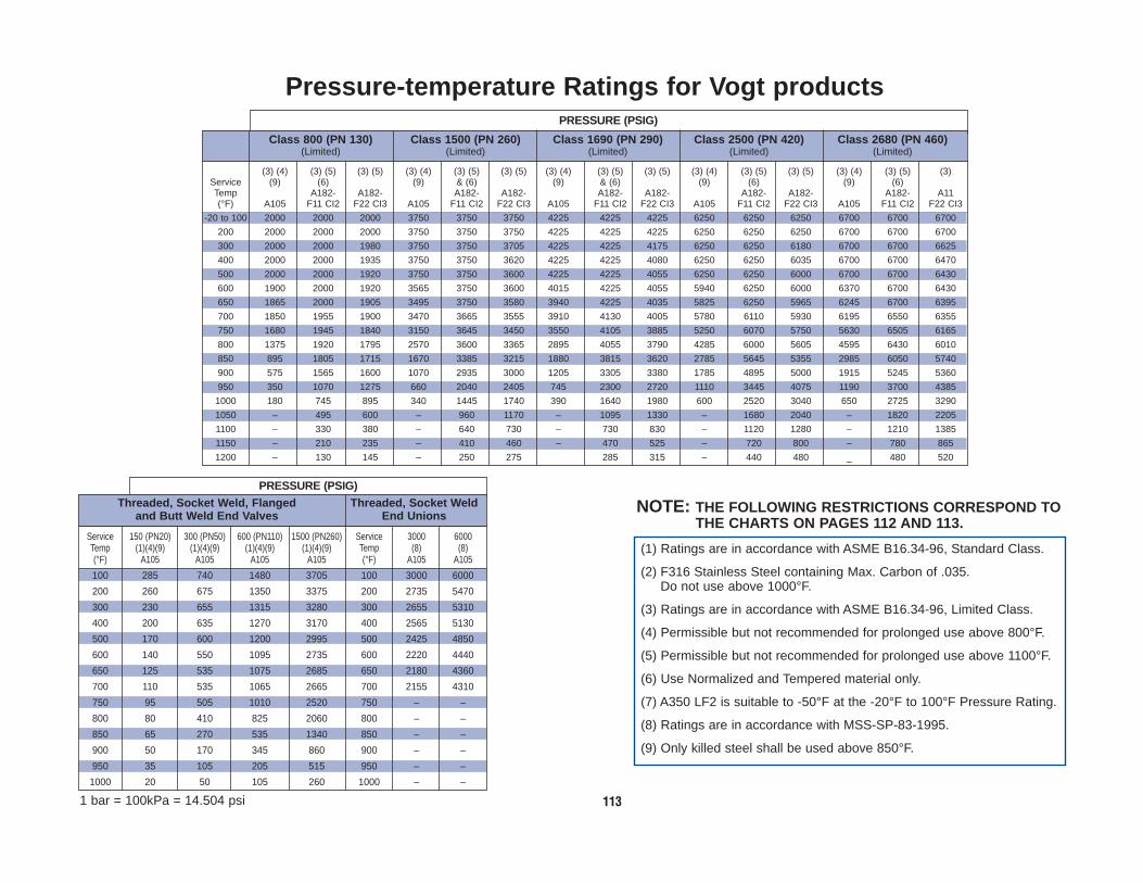
113
PRESSURE (PSIG)
Class 800 (PN 130) Class 1500 (PN 260) Class 1690 (PN 290) Class 2500 (PN 420) Class 2680 (PN 460)(Limited) (Limited) (Limited) (Limited) (Limited)
PRESSURE (PSIG)Threaded, Socket Weld, Flanged Threaded, Socket Weld
and Butt Weld End Valves End Unions
Pressure-temperature Ratings for Vogt products
(1) Ratings are in accordance with ASME B16.34-96, Standard Class.
(2) F316 Stainless Steel containing Max. Carbon of .035. Do not use above 1000°F.
(3) Ratings are in accordance with ASME B16.34-96, Limited Class.
(4) Permissible but not recommended for prolonged use above 800°F.
(5) Permissible but not recommended for prolonged use above 1100°F.
(6) Use Normalized and Tempered material only.
(7) A350 LF2 is suitable to -50°F at the -20°F to 100°F Pressure Rating.
(8) Ratings are in accordance with MSS-SP-83-1995.
(9) Only killed steel shall be used above 850°F.
(3) (4) (3) (5) (3) (5) (3) (4) (3) (5) (3) (5) (3) (4) (3) (5) (3) (5) (3) (4) (3) (5) (3) (5) (3) (4) (3) (5) (3)Service (9) (6) (9) & (6) (9) & (6) (9) (6) (9) (6)Temp A182- A182- A182- A182- A182- A182- A182- A182- A182- A11(°F) A105 F11 CI2 F22 CI3 A105 F11 CI2 F22 CI3 A105 F11 CI2 F22 CI3 A105 F11 CI2 F22 CI3 A105 F11 CI2 F22 CI3
-20 to 100 2000 2000 2000 3750 3750 3750 4225 4225 4225 6250 6250 6250 6700 6700 6700
200 2000 2000 2000 3750 3750 3750 4225 4225 4225 6250 6250 6250 6700 6700 6700
300 2000 2000 1980 3750 3750 3705 4225 4225 4175 6250 6250 6180 6700 6700 6625
400 2000 2000 1935 3750 3750 3620 4225 4225 4080 6250 6250 6035 6700 6700 6470
500 2000 2000 1920 3750 3750 3600 4225 4225 4055 6250 6250 6000 6700 6700 6430
600 1900 2000 1920 3565 3750 3600 4015 4225 4055 5940 6250 6000 6370 6700 6430
650 1865 2000 1905 3495 3750 3580 3940 4225 4035 5825 6250 5965 6245 6700 6395
700 1850 1955 1900 3470 3665 3555 3910 4130 4005 5780 6110 5930 6195 6550 6355
750 1680 1945 1840 3150 3645 3450 3550 4105 3885 5250 6070 5750 5630 6505 6165
800 1375 1920 1795 2570 3600 3365 2895 4055 3790 4285 6000 5605 4595 6430 6010
850 895 1805 1715 1670 3385 3215 1880 3815 3620 2785 5645 5355 2985 6050 5740
900 575 1565 1600 1070 2935 3000 1205 3305 3380 1785 4895 5000 1915 5245 5360
950 350 1070 1275 660 2040 2405 745 2300 2720 1110 3445 4075 1190 3700 4385
1000 180 745 895 340 1445 1740 390 1640 1980 600 2520 3040 650 2725 3290
1050 – 495 600 – 960 1170 – 1095 1330 – 1680 2040 – 1820 2205
1100 – 330 380 – 640 730 – 730 830 – 1120 1280 – 1210 1385
1150 – 210 235 – 410 460 – 470 525 – 720 800 – 780 865
1200 – 130 145 – 250 275 285 315 – 440 480 _ 480 520
Service 150 (PN20) 300 (PN50) 600 (PN110) 1500 (PN260) Service 3000 6000Temp (1)(4)(9) (1)(4)(9) (1)(4)(9) (1)(4)(9) Temp (8) (8)(°F) A105 A105 A105 A105 (°F) A105 A105
100 285 740 1480 3705 100 3000 6000
200 260 675 1350 3375 200 2735 5470
300 230 655 1315 3280 300 2655 5310
400 200 635 1270 3170 400 2565 5130
500 170 600 1200 2995 500 2425 4850
600 140 550 1095 2735 600 2220 4440
650 125 535 1075 2685 650 2180 4360
700 110 535 1065 2665 700 2155 4310
750 95 505 1010 2520 750 – –
800 80 410 825 2060 800 – –
850 65 270 535 1340 850 – –
900 50 170 345 860 900 – –
950 35 105 205 515 950 – –
1000 20 50 105 260 1000 – –
1 bar = 100kPa = 14.504 psi
NOTE: THE FOLLOWING RESTRICTIONS CORRESPOND TO THE CHARTS ON PAGES 112 AND 113.

114
PN 130 (Class 800) PN 260 (Class 1500)(Standard) (Standard)
PRESSURE (BAR) PRESSURE (BAR)
(1) (4) (1) (1) (2) (1) (1) (4) (1) (1) (5) (1) (5) (1) (4) (1) (1) (2) (1) (1) (4) (1) (1) (5) (1) (5)Service (9) (7) & (6) (9) (7) & (6)Temp A182- A182- A182- A350- A182- A182- A182- A182- A182- A182- A350- A182- A182- A182-(°C) A105 F5 F316 F316H LF2 F9 F11 C12 F22 C13 A105 F5 F316 F316H LF2 F9 F11 C12 F22 C13
-29 to 38 136.2 137.9 132.4 132.4 136.2 137.9 137.9 137.9 255.5 258.6 248.3 248.3 255.5 258.6 258.6 258.6
50 133.6 137.7 128.4 128.4 133.6 137.9 137.9 137.9 250.5 258.2 240.6 240.6 250.5 258.6 258.5 258.6
100 123.7 136.3 112.8 112.8 123.7 137.4 137.3 137.4 232.0 255.7 211.0 211.0 232.0 257.7 257.5 257.7
150 120.6 131.7 102.9 102.9 120.6 133.7 132.7 133.7 226.1 246.8 192.4 192.4 226.1 250.9 248.8 250.9
200 116.9 129.8 95.2 95.2 116.9 130.0 128.0 130.0 219.2 243.7 178.5 178.5 219.2 244.1 239.8 244.1
250 111.2 123.7 89.1 89.1 111.2 123.7 123.3 123.7 208.7 231.9 167.1 167.1 208.7 231.9 231.0 231.9
300 103.3 114.5 84.5 84.5 103.3 114.5 114.5 114.5 193.6 214.4 158.1 158.1 193.6 214.4 214.4 214.4
350 98.5 107.4 81.3 81.3 98.5 107.4 107.4 107.4 184.8 201.1 152.3 152.3 184.8 201.1 201.1 201.1
375 97.2 103.5 79.8 79.8 97.2 103.6 103.6 103.6 182.4 193.9 149.3 149.3 182.4 194.1 194.1 194.1
400 92.1 97.1 78.6 78.6 92.1 97.8 97.8 97.8 172.5 181.8 147.2 147.2 172.5 183.1 183.1 183.1
425 76.9 93.7 77.6 77.6 76.9 93.7 93.7 93.7 144.0 175.6 145.6 145.6 144.0 175.7 175.7 175.7
450 53.6 89.7 77.0 77.0 53.6 90.3 90.3 90.3 100.4 167.9 144.4 144.4 100.4 169.1 169.1 169.1
475 36.3 73.4 76.4 76.4 36.3 84.6 84.6 84.6 67.9 137.7 143.4 143.4 67.9 158.2 158.2 158.2
500 23.6 56.9 72.9 72.9 23.6 74.2 67.3 74.2 44.1 106.4 136.7 136.7 44.1 138.9 126.1 138.9
525 13.9 43.1 67.5 67.5 13.9 57.0 48.4 57.8 26.0 80.5 126.4 126.4 26.0 107.1 90.8 108.4
538 9.7 36.5 64.5 64.5 9.7 46.4 39.7 47.8 17.9 68.5 120.7 120.7 17.9 87.4 74.3 89.8
550 – 32.2 – 63.9 – 40.0 33.9 41.0 – 60.3 – 119.8 – 75.0 63.6 77.0
575 – 23.7 – 60.8 – 28.0 23.5 28.1 – 44.4 – 114.0 – 52.2 44.0 52.7
600 – 16.6 – 53.1 – 19.0 16.1 18.4 – 31.1 – 99.5 – 35.8 30.3 34.5
625 – 10.7 – 42.1 – 13.2 10.8 11.7 – 20.0 – 79.2 – 24.7 20.2 22.4
650 – 6.6 – 33.8 – 9.7 6.9 7.6 – 11.7 – 63.3 – 17.6 13.1 14.1
675 – – – 27.3 – – – – – – – 51.5 – – – –
700 – – – 22.3 – – – – – – – 42.0 – – – –
725 – – – 18.6 – – – – – – – 35.0 – – – –
750 – – – 15.2 – – – – – – – 28.7 – – – –
775 – – – 12.1 – – – – – – – 22.9 – – – –
800 – – – 9.3 – – – – – – – 17.4 – – – –
816 – – – 7.6 – – – – – – – 14.1 – – – –
1 bar = 100kPa = 14.504 psi SEE NOTE ON PAGE 115 FOR RATING RESTRICTIONS.
Pressure-temperature Ratings (metric) for Vogt products

115
PRESSURE (PSIG)Threaded, Socket Weld, Flanged Threaded, Socket Weld
and Butt Weld End Valves End Unions
Service PN20 (CL150) PN 50 (CL300) PN 110 (CL600) PN260 (CL1500) Service 3000 6000Temp (1)(4)(9) (1)(4)(9) (1)(4)(9) (1)(4)(9) Temp (8) (8)(°C) A105 A105 A105 A105 (°C) A105 A105
-29 to 38 19.7 51.0 102.1 255.5 -29 to 38 206.9 413.850 19.3 50.0 100.1 250.5 50 202.9 405.7100 17.7 46.4 92.8 232.0 100 187.9 375.9150 15.8 45.1 90.6 226.1 150 183.0 366.0200 14.0 43.9 87.8 219.2 200 177.4 354.8250 12.1 41.8 83.6 208.7 250 168.9 338.0300 10.2 38.9 77.5 193.6 300 157.0 314.1350 8.4 36.9 74.0 184.8 350 149.9 299.9375 7.4 36.6 72.9 182.4 371 148.6 297.2400 6.5 34.6 69.1 172.5 – – –425 5.6 28.7 57.7 144.0 – – –450 4.6 20.2 40.1 100.4 – – –475 3.7 13.5 27.2 67.9 – – –500 2.8 8.9 17.6 44.1 – – –525 1.9 5.2 10.4 26.0 – – –538 1.4 3.4 7.2 17.9 – – –
PRESSURE (PSIG)
PN 130 (Class 800) PN 260 (Class 1500) PN 290 (Class 1690) PN 420 (Class 2500) PN 460 (Class 2680)(Limited) (Limited) (Limited) (Limited) (Limited)
(3) (4) (3) (5) (3) (5) (3) (4) (3) (5) (3) (5) (3) (4) (3) (5) (3) (5) (3) (4) (3) (5) (3) (5) (3) (4) (3) (5) (3)Service (9) (6) (9) & (6) (9) & (6) (9) (6) (9) (6)Temp A182- A182- A182- A182- A182- A182- A182- A182- A182- A11(°C) A105 F11 CI2 F22 CI3 A105 F11 CI2 F22 CI3 A105 F11 CI2 F22 CI3 A105 F11 CI2 F22 CI3 A105 F11 CI2 F22 CI3
-29 to 38 137.9 137.9 137.9 258.6 258.6 258.6 291.4 291.4 291.4 431.0 431.0 431.0 462.1 462.1 462.150 137.9 137.9 137.9 258.6 258.6 258.6 291.4 291.4 291.4 431.0 431.0 431.0 462.1 462.1 462.1100 137.9 137.9 137.8 258.6 258.6 258.2 291.4 291.4 291.0 431.0 431.0 430.5 462.1 462.1 461.4150 137.9 137.9 136.5 258.6 258.6 255.4 291.4 291.4 287.8 431.0 431.0 426.0 462.1 462.1 456.7200 137.9 137.9 133.7 258.6 258.6 250.1 291.4 291.4 281.9 431.0 431.0 417.0 462.1 462.1 447.1250 137.9 137.9 132.6 258.6 258.6 248.5 291.4 291.4 280.0 431.0 431.0 414.2 462.1 462.1 443.9300 133.0 137.9 132.4 249.4 258.6 248.3 281.0 291.4 279.7 415.6 431.0 413.8 445.7 462.1 443.4350 128.4 137.2 131.3 240.6 257.2 246.5 271.2 289.8 277.8 401.0 428.7 410.8 429.9 459.6 440.4375 125.9 134.7 130.5 236.2 252.6 244.2 266.2 284.6 275.0 393.5 421.0 407.2 421.8 451.3 436.4400 115.0 134.1 126.8 215.6 251.3 237.7 243.0 283.0 267.7 359.4 418.4 396.2 385.4 448.4 424.7425 96.1 132.5 124.0 179.6 248.5 232.4 202.4 279.9 261.8 299.5 414.1 387.2 321.2 443.8 415.1450 67.0 125.8 119.2 125.1 235.8 223.4 140.9 265.8 251.5 208.6 393.2 372.1 223.6 421.4 398.8475 45.4 112.2 112.4 84.6 210.5 210.8 95.2 237.1 237.4 141.0 351.0 351.2 151.3 376.2 376.5500 29.7 86.1 96.0 55.7 162.9 180.6 62.8 183.6 204.0 93.3 273.6 304.0 100.1 293.5 326.6525 17.8 61.7 73.8 33.6 118.5 141.1 38.2 134.0 160.0 57.6 203.1 242.5 62.0 218.9 261.6538 12.4 51.2 61.6 23.4 99.4 119.7 26.9 112.8 136.2 41.4 173.3 209.1 44.8 187.4 226.3550 – 43.8 52.8 – 84.9 102.7 – 96.6 116.8 – 148.3 179.3 – 160.5 194.0575 – 30.3 36.2 – 58.7 70.4 – 67.0 80.0 – 102.7 122.9 – 111.2 132.8600 – 20.8 23.8 – 40.3 45.9 – 46.0 52.2 – 70.6 80.3 – 76.3 86.9625 – 13.7 15.3 – 26.7 29.9 – 30.6 34.2 – 47.0 52.1 – 50.9 56.3649 – 9.0 10.0 – 17.2 19.0 – 19.7 21.7 – 30.3 33.1 – 33.1 35.9
1 bar = 100kPa = 14.504 psi
(1) Ratings are in accordance with ASME B16.34-96, Standard Class.
(2) F316 Stainless Steel containing Max. Carbon of .035. Do not use above 1000°F.
(3) Ratings are in accordance with ASME B16.34 -96, Limited Class.
(4) Permissible but not recommended for prolonged use above 800°F.
(5) Permissible but not recommended for prolonged use above 1100°F.
(6) Use Normalized and Tempered material only.
(7) A350 LF2 is suitable to -50°F at the -20°F to 100°F Pressure Rating.
(8) Ratings are in accordance with MSS-SP-83-1995.
(9) Only killed steel shall be used above 850°F.
NOTE: THE FOLLOWING RESTRICTIONS CORRESPOND TO THE CHARTS ON PAGES 114 AND 115.
Pressure-temperature Ratings (metric) for Vogt products

116
Meeting the Demands of Today
Asbestos-Free ValvesAsbestos-Free Packing
Asbestos-Free GasketSAFE—EFFICIENT in retaining high and low temperature media
ADVANCED TECHNOLOGY PROVIDES:
■ Environmental acceptance■ Elimination of media contamination■ Leak-proof integrity ■ High thermal conductivity ■ Self-lubricating operation ■ Shrinkage resistance ■ Corrosion resistant inhibitor ■ Less frequent maintenance ■ Longer service life
STANDARD PACKINGVogt standard valves are packed with one of the following asbestos-free packing sets:
FLEXIBLE GRAPHITE PACKINGA 95% by weight minumum carbon packing set that consists of a cylindrical ring of flexiblegraphite packing supported on the top and bottom with braided graphite filament packingrings. The packing set contains a dispersed and embedded active corrosion inhibitor toprotect against stem pitting. It may be used in fluids having a pH range of 0-14. Thepacking has minimal residues as follows:
Leachable Chlorides: 100PPM MaximumTotal Chlorides: 500PPM MaximumTotal Sulfur: 1000PPM MaximumPTFE: None
MOLDED TFE TEFLON SHAPED PACKINGVogt valves that have a series number suffixed with the letter “T” are packed with a moldedshaped TFE packing. This virgin TFE material needs no corrosion inhibitor in itscomposition and its self-energizing shape assures superior service with low gland boltingloads in high pressure liquid and dry gas applications. It may also be used in fluids havinga pH range of 0-14. Temperature range: -120°F to 500°F (-84° to 260°C).
Since this packing has directional sealing, it can be reoriented for valves used in vacuumand/or combination vacuum/pressure service.
OTHER PACKINGOther packing sets can be placed in Vogt valves at the user’s option.
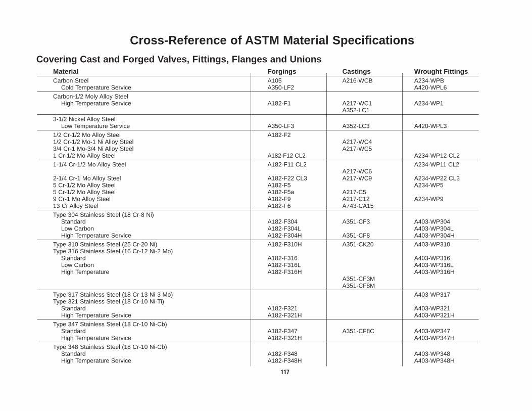
117
Cross-Reference of ASTM Material Specifications
Covering Cast and Forged Valves, Fittings, Flanges and UnionsMaterial Forgings Castings Wrought FittingsCarbon Steel A105 A216-WCB A234-WPB
Cold Temperature Service A350-LF2 A420-WPL6
Carbon-1/2 Moly Alloy Steel High Temperature Service A182-F1 A217-WC1 A234-WP1
A352-LC1
3-1/2 Nickel Alloy Steel Low Temperature Service A350-LF3 A352-LC3 A420-WPL3
1/2 Cr-1/2 Mo Alloy Steel A182-F21/2 Cr-1/2 Mo-1 Ni Alloy Steel A217-WC43/4 Cr-1 Mo-3/4 Ni Alloy Steel A217-WC51 Cr-1/2 Mo Ailoy Steel A182-F12 CL2 A234-WP12 CL2
1-1/4 Cr-1/2 Mo Alloy Steel A182-F11 CL2 A234-WP11 CL2A217-WC6
2-1/4 Cr-1 Mo Alloy Steel A182-F22 CL3 A217-WC9 A234-WP22 CL35 Cr-1/2 Mo Alloy Steel A182-F5 A234-WP55 Cr-1/2 Mo Alloy Steel A182-F5a A217-C59 Cr-1 Mo Alloy Steel A182-F9 A217-C12 A234-WP913 Cr Alloy Steel A182-F6 A743-CA15
Type 304 Stainless Steel (18 Cr-8 Ni)Standard A182-F304 A351-CF3 A403-WP304Low Carbon A182-F304L A403-WP304LHigh Temperature Service A182-F304H A351-CF8 A403-WP304H
Type 310 Stainless Steel (25 Cr-20 Ni) A182-F310H A351-CK20 A403-WP310Type 316 Stainless Steel (16 Cr-12 Ni-2 Mo)
Standard A182-F316 A403-WP316Low Carbon A182-F316L A403-WP316LHigh Temperature A182-F316H A403-WP316H
A351-CF3MA351-CF8M
Type 317 Stainless Steel (18 Cr-13 Ni-3 Mo) A403-WP317Type 321 Stainless Steel (18 Cr-10 Ni-Ti)
Standard A182-F321 A403-WP321High Temperature Service A182-F321H A403-WP321H
Type 347 Stainless Steel (18 Cr-10 Ni-Cb) Standard A182-F347 A351-CF8C A403-WP347High Temperature Service A182-F321H A403-WP347H
Type 348 Stainless Steel (18 Cr-10 Ni-Cb) Standard A182-F348 A403-WP348High Temperature Service A182-F348H A403-WP348H

118
Forging Materials
ASTM A105 Carbon SteelWhere temperatures are moderate and corrosion resistance is not critical.
C 0.20 - 0.24 Mn 1.00 - 1.35 Si 0.15 - 0.30 P .030 Max. S 0.015 - 0.040 Cr 0.20 Ni 0.20 Mo 0.06 V 0.02 Cb 0.02 Cu 0.20 Pb 0.02 Total Residuals = 0.50
TS Min. psi(MPa) 70,000(485) YS Min. psi(MPa) 36,000(250) EL (2” Min.) 22% RA Min. 30% Hardness, Bhn Max. 187
Chemistry Element – % Composition Mechanical Properties Chemistry Element – % Composition Mechanical Properties
ASTM A350, LF2Where cold temperature (-50°F) impact strength is essential.
C 0.20 - 0.24 Mn 1.00 - 1.35 Si 0.15 - 0.30 P .030 Max. S 0.015 - 0.040 Cr 0.20 Ni 0.20 Mo 0.06 V 0.02 Cb 0.02 Cu 0.20 Pb 0.02 Total Residuals = 0.50
TS Min. psi(MPa) 70,000(485) YS Min. psi(MPa) 36,000(250)EL (2” Min.) 22% RA Min. 30% Hardness, Bhn Max. 197-50°F Charpy Min. ImpactEnergy (Ft./Lb.) (J)Average of Each Set of 3 Specimen 15(20)For One Specimen 12(16)
C 0.10 - 0.15 Mn 0.30 - 0.80 P .040 Max. S 0.015 - 0.035 Si 0.50 - 1.00 Cr 1.00 - 1.50 Mo 0.44 - 0.65
TS Min. psi(MPa) 70,000(485) YS Min. psi(MPa) 40,000(275) EL (2” Min.) 20% RA Min. 30% Hardness, Bhn 143-207
ASTM A182, Grade F11, Class 2 – 1 1/4% Chromium 1/2% MoIybdenumTo minimize graphitization encountered with carbon and carbon moly steels at high temperatures.
C 0.15 Max.Mn 0.30 - 0.60 P .040 Max. S 0.015 - 0.035 Si 0.50 MaxCr 2.00 - 2.50 Mo 0.87 - 1.13
TS Min. psi(MPa) 75,000(515) YS Min. psi(MPa) 40,000(310) EL (2” Min.) 20% RA Min. 30% Hardness, Bhn 156-207
ASTM A182, Grade F22, Class 3 – 2 1/4% Chromium 1% MoIybdenumWhere elevated temperature, surface stability, and greater strength than F11 are needed.
C 0.15 Max.Mn 0.30 - 0.60 P .030 Max. S 0.015 - 0.035 Si 0.50 MaxNi 0.50 MaxCr 4.00 - 6.00 Mo 0.44 - 0.65
TS Min. psi(MPa) 70,000(485) YS Min. psi(MPa) 40,000(275) EL (2” Min.) 20% RA Min. 35% Hardness, Bhn 143-217
ASTM A182, Grade 5 – 4-6% Chromium 1/2% MoIybdenumWith moderately corrosive fluids and in oil refineries where high temperature stability andoxidation resistance of the lower alloy steels are inadequate.
C 0.15 Max.Mn 0.30 - 0.60 P .030 Max. S 0.030 MaxSi 0.50 - 1.00 Cr 8.00 - 10.00 Mo 0.90 - 1.10
ASTM A182, Grade F9 – 9% Chromium For services where the higher chrome alloys are preferred and where high temperature stabilityand oxidation resistance of the lower alloy steels are inadequate.
TS Min. psi(MPa) 85,000(585) YS Min. psi(MPa) 55,000(380) EL (2” Min.) 20% RA Min. 40% Hardness, Bhn 179-217
C 0.035 Max.Mn 2.00 Max. P .040 Max. S 0.020 - 0.030 Si 1.00 MaxNi 10.00 - 14.00 Cr 16.00 - 18.00 Mo 2.00 - 3.00
ASTM A182, Grade F316. Grade F316L – 18% Chromium 8% Nickel 2-3% MoIybdenumFor corrosion resistance applications where high temperature strength is required. Hasrestricted carbon level to minimize sensitization. Do not use for service temperatures above1000°F.
TS Min. psi(MPa) 75,000(515) YS Min. psi(MPa) 30,000(205) EL (2” Min.) 30% RA Min. 30%
C 0.04 - 0.10 Mn 2.00 Max.P .040 Max. S 0.020 - 0.030 Si 1.00 MaxNi 10.00 - 14.00Cr 16.00 - 18.00Mo 2.00 - 3.00
ASTM A182, Grade F316H – 18% Chromium 8% Nickel 2-3% MoIybdenumFor corrosion resistance applications where extreme high temperature service is expected. Hasa restricted carbon range for high temperature strength above 1000°F.
TS Min. psi(MPa) 75,000(515) YS Min. psi(MPa) 30,000(205) EL (2” Min.) 30% RA Min. 30%

119
Valve Trim Materials
13% Chromium Stainless Steel Type 410ASTM A479This stainless steel material lends itselfreadily to hardening by heat treatment and isexcellent for contacting parts such as stems,gates, and discs.
C 0.10- 0.15 Mn .60 Max.P .040 Max. S .030 Max.Si 1.00 MaxCr 12 - 13.5
Description & General Use Chemistry Element % Composition Description & General Use Chemistry Element % Composition
13% Chromium Stainless Steel Type 416ASTM A582High quality stainless steel yoke nut materialhaving excellent anti-galling characteristic forbetter operating threads.
C 0.11- 0.14Mn .60 Max.P .060 Max. S 0.25 - 0.35 Si 1.00 MaxCr 12.00 - 14.00 Ni .60 Max.
18% Chromium 8% Nickel,2% MolybdenumStainless Steel Type 316Type 316LASTM A182Provides excellent resistance to corrosivemedia at high temperatures and toughnessfor service at low temperatures.
C .035 Max. Mn 2.00 Max.P .040 Max. S 0.020 - .030 Si 1.00 MaxCr 16.00 - 18.00 Ni 10.00 - 14.00 Mo 2.00 - 3.00
Nickel-CopperMonelAlloy K500FED-SPEC QQ-N-286F Class AThis wrought material is precipitationhardened and possesses excellent corrosionresistance, high strength properties andhardness for internal valve components.
MonelAlloy 400ASTM B164 (N0400)Non hardened alloy, except by workhardened, that has high strength andtoughness over a wide temperature range.Has excellent corrosion resistance in chlorineand alkylation service.
C .25 Max. Mn 1.50 Max.S 0.010 Max.Ni 63.00 - 70.00 Si .50 MaxFe 2.00 MaxAl 2.3 - 3.15 Ti .35 - .85 Cu 27.0 - 33.0 P 0.020Zn 0.020Pb 0.006Sn 0.006
C .030 Max.Mn 2.00 Max.S .024 Max. Si 0.50 MaxNi 63.00 - 70.00 Fe 2.50 MaxCu 27.0 - 33.0
Cobalt Base and Nickel Base Hard Facing MaterialsASME SFA 5.13Hard facing materials, when used on seatingsurfaces of Gate, Globe, and Check Valves,give extended service life and troublefreeoperation.
– Cobalt, Chromium and Tungsten Alloy– Nickel, Chromium and Boron Alloy
Nickel-Moly-Chromium ASTM B574, Grade N 10276 Hastelloy C-276A high nickel alloy with exceptional resistanceto corrosive attack by chlorine gas.
C .02 Max. Ni BalanceCo 2.5 Max. Cr 14.50 - 16.50 Mo 15.00 - 17.00W 3.00 - 4.50
Fe 4.00 - 7.00 Si 0.08 MaxMn 1.00 Max. V .35 Max.P .04 Max.S .03 Max.
C 0.07 MaxMn 1.00 Max. P .04 Max.S .03 Max.Si 1.00 Max
Cr 15.00 - 17.50Ni 3.00 - 5.00 Cu 3.00 - 5.00 Cb +Ta 0.15 - 0.45
C .25 Max.Mn 1.50 Si 3.5 - 4.5 P .03
S .03Ni BalanceFe 3.5Cu 27.00 - 33.00
Precipitation Hardened Stainless SteelA564, Gr. 630 17-4 PHProvides corrosion resistance and highstrength for stems in NACE applications.
S-Monel ASTM A-494, Grade M-25SMaterial used for Monel castings.
C .15 Max.Mn 1.00 Si 1.50 Max.P .040
S .040 Max.Cr 11.50 - 14.00Ni 1.0 Max.Mo .50 Max.
ASTM A-743, Grade CA-15 Material used for 13 CR castings, the castequivalent to type 410 Stainless Steel.
C 0.9-1.4Mn 1.0 Si 1.5 Ni 3.0Cr 27.0 - 31.0
Mo 1.0W 3.5 - 5.5Fe 3.0Others .50Co Balance
Cast CobaltASME-SFA–5.13RCoCr-AMaterial used for Cobalt castings, the castequivalent to Stellite #6.
C 08 MaxMn 1.50 MaxP .040 Max S .040 Max Si 1.50 Max
Cr 18.0-21.0
Ni 9.0-12.0
Mo 2.0-3.0
ASTM A351Grade CF8MMaterial used for 18-8 castings, the castequivalent to type 316 stainless steel.

120
Flow Data Utilizing Cv Factors
▲▲ P
S
▲▲ P x P1
T1Sg
▲▲ P x P1
▲▲ P x P1
▲▲ P = SQ
Cv( )2Q = CvLIQUID
GAS
WHEN ▲▲ P � .5P1
WHEN ▲▲ P � .5P1
q´m = 22.6 Cv
Sg T1
13.9 P1Cvq´m =
1.82 Cv P1
(1 + .0007S)W =
2.97 Cv
(1 + .0007S)W =
W = 2.97 Cv
W = 1.82 Cv P1
▲▲ P = q´m
Cv( )2.00195 T1Sg
P1
▲▲ P = W
Cv( )2.113
P1
▲▲ P = W(1 + .0007s)
Cv( )2.113
P1
WHEN ▲▲ P � .5P1
WHEN ▲▲ P � .5P1
WHEN ▲▲ P � .5P1
WHEN ▲▲ P � .5P1
DRY SATURATED STEAM
SUPERHEATED STEAM
TYPE FLOW FLOW RATE PRESSURE DROPFORMULAS
Cv – Flow coefficient for valvesand fittings.
P1 – Absolute inlet pressure.(PSIA)
P2 – Absolute outlet pressure.(PSIA)
▲▲ P – Pressure drop in poundsper square inch. (PSI)
Q – Liquid flow in gallons perminute. (GPM)
q´m – Rate of gas flow in cubicfeet per minute atstandard conditions, 14.7psia and 60°F. (SCFM)
S – Specific gravity of flowingliquid relative to water at60°F.
Sg – Specific gravity of gasrelative to air.
s – Number of degrees ofsuperheat for steam in °F.
T1 – Absolute inlet temperaturein degrees Rankine. (°R)
W – Steam or vapor flow ratein pounds per hour.(LBS./HR.)
Fluid FlowNomenclature
��
��
�

121
Flow Data Utilizing Cv Factors (Metric Version)
▲▲ P
S
▲▲ P x P1
T1Sg
▲▲ P x P1
▲▲ P x P1
▲▲ P = 1.34SQ
Cv( )2Q = .865CvLIQUID
GAS
WHEN ▲▲ P � .5P1
WHEN ▲▲ P � .5P1
q´H = 414.97 Cv
Sg T1
255.2 P1Cvq´m =
11.71 Cv x P1
(1 + 0.00123S)W =
19.1 Cv
(1 + 0.00123S)W =
W = 19.53 Cv
W = 11.97 Cv P1
▲▲ P = q´HCv( )25.81x10⁻⁶ T1Sg
P1
▲▲ P = W
Cv( )2.00262
P1
▲▲ P = W(1 + 0.00123s)
Cv( )2
0.00274
P1
WHEN ▲▲ P � .5P1
WHEN ▲▲ P � .5P1
WHEN ▲▲ P � .5P1
WHEN ▲▲ P � .5P1
DRY SATURATED STEAM
SUPERHEATED STEAM
TYPE FLOW FLOW RATE PRESSURE DROPFORMULAS
Cv – Flow coefficient for valvesand fittings.
P1 – Absolute inlet pressure.(BAR)
P2 – Absolute outlet pressure.(BAR)
▲▲ P – Pressure drop in bars.
Q – Liquid flow in cubic metersper hour.
q´H – Rate of gas flow in cubicmeters per hour atstandard conditions, 1.01BAR @ 15.6°C.
S – Specific gravity of flowingliquid relative to water at16°C.
Sg – Specific gravity of gasrelative to air.
s – Number of degrees ofsuperheat for steam in °C.
T1 – Absolute inlet temperaturein degrees Kelvin. (°K)
W – Steam or vapor flow rate inkilograms per hour.(KGS./HR.)
Fluid FlowNomenclature
��
��
�
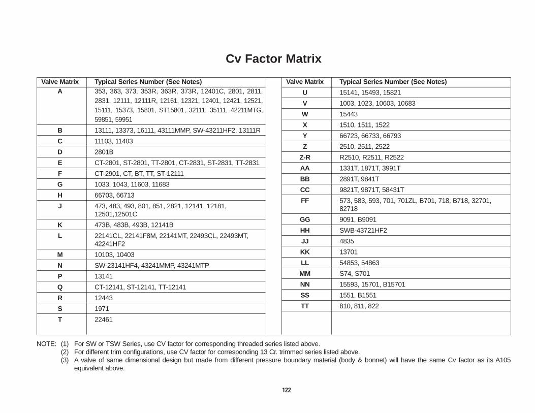
122
Cv Factor Matrix
Valve Matrix Typical Series Number (See Notes)A 353, 363, 373, 353R, 363R, 373R, 12401C, 2801, 2811,
2831, 12111, 12111R, 12161, 12321, 12401, 12421, 12521,15111, 15373, 15801, ST15801, 32111, 35111, 42211MTG,59851, 59951
B 13111, 13373, 16111, 43111MMP, SW-43211HF2, 13111R
C 11103, 11403
D 2801B
E CT-2801, ST-2801, TT-2801, CT-2831, ST-2831, TT-2831
F CT-2901, CT, BT, TT, ST-12111
G 1033, 1043, 11603, 11683
H 66703, 66713
J 473, 483, 493, 801, 851, 2821, 12141, 12181,12501,12501C
K 473B, 483B, 493B, 12141B
L 22141CL, 22141F8M, 22141MT, 22493CL, 22493MT,42241HF2
M 10103, 10403
N SW-23141HF4, 43241MMP, 43241MTP
P 13141
Q CT-12141, ST-12141, TT-12141
R 12443
S 1971
T 22461
Valve Matrix Typical Series Number (See Notes)
U 15141, 15493, 15821
V 1003, 1023, 10603, 10683
W 15443
X 1510, 1511, 1522
Y 66723, 66733, 66793
Z 2510, 2511, 2522
Z-R R2510, R2511, R2522
AA 1331T, 1871T, 3991T
BB 2891T, 9841T
CC 9821T, 9871T, 58431T
FF 573, 583, 593, 701, 701ZL, B701, 718, B718, 32701,82718
GG 9091, B9091
HH SWB-43721HF2
JJ 4835
KK 13701
LL 54853, 54863
MM S74, S701
NN 15593, 15701, B15701
SS 1551, B1551
TT 810, 811, 822
NOTE: (1) For SW or TSW Series, use CV factor for corresponding threaded series listed above.(2) For different trim configurations, use CV factor for corresponding 13 Cr. trimmed series listed above.(3) A valve of same dimensional design but made from different pressure boundary material (body & bonnet) will have the same Cv factor as its A105
equivalent above.

123
Cv Factors
These Cv factors have been established by testing valves using Schedule 40 pipe except as noted.** Sch. 160 used for testing valve.***Sch. XXH used for testing valve.
1/4 3/8 1/2 3/4 1 1 1/4 1 1/2 2 2 1/2 3 4Size NPS 8 10 15 20 25 32 40 50 65 80 100
A 2.6 3.9 9.6 9.7 20.3 80.5 91.6 117.6 174 203.9 230.0
B – – 9.6 28.7 46.5 80.5 109.6 181.0 – – –
C – – 9.6 28.7 46.5 80.5 109.6 181.0 242.3 322.7 –
D – – 9.6 9.7 20.3 – 109.6 117.6 – – –
E – – 6.5 9.0 27.7 – 78.0 – – – –
F – – 9.6 9.7 20.3 – 78.0 – – – –
G – – 11.8 28.7 32.0 83.2 109.6 181.0 – – –
H – – 5.0 17.5 16.1 – 109.6 100.2 – – –
J 1.3 2.0 2.4 4.3 7.3 14.2 20.4 23.1 – – –
K – – 2.2 5.7 5.2 – 21.1 20.5 – – –
L .7 1.7 1.7 3.1 5.9 13.7 18.4 22.5 – – –
M – – 3.4 7.3 11.9 15.6 28.2 46.9 – 85.1 –
N – – .7 5.9 13.7 – 21.0 34.0 – – –
P .9 2.5 3.0 6.8 14.5 17.2 24.4 37.6 – – –
Q – – 2.4 4.3 7.3 – 20.4 – – – –
R – – 1.46 2.38 4.54 – 9.65 14.6 – – –
S 1.1 2.1 2.6 4.5 11.9 21.0 31.4 52.0 – – –
T .56 .55 .68 .99 1.5 – – – – – –
U** – – 3.1 3.3 5.9 – 13.8 21.4 – – –
1/4 3/8 1/2 3/4 1 1 1/4 1 1/2 2 2 1/2 3 4Size NPS 8 10 15 20 25 32 40 50 65 80 100
V – – 3.6 6.0 10.2 15.1 24.2 39.8 – – –
W – – 1.46 2.38 4.54 – 11.5 13.0 – – –
X** – – 6.0 4.0 9.3 – 57.8 48.9 – – –
Y*** – – 1.2 4.3 5.8 – 17.6 19.3 – – –
Z*** – – 1.8 4.3 9.4 – 32.7 49.4 – – –
Z-R*** – – 1.5 3.9 7.9 – 29.3 39.8 – – –
AA 1.4 1.3 2.9 3.8 8.1 15.3 18.4 25.5 – – –
BB 1.1 1.7 2.6 4.5 11.9 19.0 25.0 49.0 – – –
CC .64 1.4 1.8 3.5 5.8 7.6 11.7 17.7 – – –
FF .9 1.5 2.1 3.2 5.8 13.3 18.3 25.3 – – –
GG 1.5 2.0 3.6 6.7 11.8 20.2 26.1 43.3 – – –
HH – – .7 5.9 11.8 – 22.6 32.6 – – –
JJ – – 3.3 4.4 17.0 28.2 43.0 63.0 – – –
KK .9 1.5 3.2 6.9 16.0 18.3 25.5 36.9 – – –
LL – – 8.7 15.1 30.5 29.1 37.7 45.3 – – –
MM – – 9.2 6.8 22.0 – 54.6 81.9 – – –
NN – – 3.2 3.3 6.3 13.3 11.0 19.6 – – –
SS 1.2 1.3 2.1 4.1 7.3 10.5 17.6 23.3 – – –
TT – – 4.5 9.1 21.3 – 70.0 79.1 – – –

124
Fitting and Union Section – Pages 124-132
VOGT’S ASME B16.11 A105 FITTINGS do
not have a Pressure/Temperature Table.
Consistent with the ASME B16.11-1996
method of pressure/temperature application
of fittings, Vogt A105 fittings have a
pressure/temperature retaining capability
equal to A106B or A106C connecting pipe
schedules (see chart).
Plugs and bushings are not identified by
class designation. They may be used for
ratings Class 6000 and lower.
Fittings are manufactured under a
traceability system in order that material
certification can be provided when required.
Class Designations:
2000, 3000, 6000
Threaded or Socket Weld
Dimensions are in inches and millimeters.
Dimensions are subject to change without notice.
Order by Size and Series Number.
Pipe(1) Used for Rating Basis
Class Designation Type of Schedule Wall
of Fitting Fitting No. Designation
2000 Threaded 80 XS3000 Threaded 160 –6000 Threaded – XXS
3000 Socket-Welding 80 XS6000 Socket-Welding 160 –9000 Socket-Welding – XXS
(1) This table is not intended torestrict the use of pipe of thinneror thicker wall with fittings. Pipeactually used may be thinner orthicker in nominal wall than thatshown. When thinner pipe isused, its strength may govern therating. When thicker pipe is used(e.g., for mechanical strength),the strength of the fitting governsthe rating.
No Longer Available
Contact Us About Marpac Unions

125
Forged Steel Strainer & Union Ells
ST
RA
INE
RS
& U
NIO
N E
LL
SS
TY
LE
300
0 –
2271
1/48
1.1228
2.2557
2.7570.94.43.91.41
3/810
1.1228
2.2557
2.7570.84.38.78.35
1-1/240
2.3860
4.381114.881246.633.016.503.0
Dimensions
Refer to pages 116-120 for full materials description.
* Strainers are furnished with 40 mesh, 31 gauge stainless steel screen.
Size
A
B
C
Weight-Series 5061
Weight-Series 6281
1/215
1.3133
2.8171
3.0076
1.30.591.63.74
3/420
1.5038
3.0678
3.4487
1.90.861.90.86
125
1.7544
3.5089
4.001023.001.362.941.3
250
2.5064
4.691195.061298.133.697.943.6
NPSDN
1-1/432
2.0051
3.8197
4.251083.881.763.881.8
THREADED MALE & FEMALE
THREADED FEMALE & FEMALE
Style 2000A105 Material2000 PSI @ 100°F (137.9 BAR @ 38°C)
SERIES NUMBER
Threaded Male & Female Union Ells5061SERIES NUMBER
Threaded Female & Female Union Ells6281
3/810
2.5064
2.3159
1.5038
3.781.7
–
1-1/2406.01525.251333.5690
16.27.4
40
DimensionsSize
A-End-to-End
B-Center-to-Bonnet End
C-Bead Diameter
Weight
Cv Factor
1/215
3.0076
2.7570
1.7544
2.241.0
6
3/420
3.5089
3.1981
2.0051
3.801.7
14
125
4.001023.5690
2.3860
5.102.3
14
250
7.501916.191574.3110928.412.9
40
NPSDN
1-1/432
4.501144.001022.6968
6.883.1
–
Bold face numerals are in inches and pounds.Blue numerals are in millimeters and kilograms.
Style 3000"Y" Type StrainerHORIZONTAL & VERTICALSCREW BONNET/SCREEN
A105 Body/Bonnet3000 PSI @ 100°F (206.9 BAR @ 38°C)
SERIES NUMBERThreaded Socket Weld2271 SW2271
Screen: 316*
Bold face numerals are in inches and pounds.Blue numerals are in millimeters and kilograms.
Size Cv Factor3/8 –DN 101/2 6DN 153/4 14DN 201 14DN 25
1-1/2 40DN 402 40DN 50
No Longer Available

126
ReadyPAK Fittings
Series Pressure 1/8 1/4 3/8 1/2 3/4 1 1-1/4 1-1/2 2
259 2000 – 25 15 15 25 20 20 15 10
229 3000 25 25 15 25 20 20 15 5 5
1299 6000 25 15 25 20 15 10 5 5 *
SW 229 3000 25 25 15 15 25 20 20 15 10
SW 1299 6000 – – – 25 20 20 10 5 *
273 2000 – 15 10 25 25 20 15 10 10
243 3000 15 20 10 25 20 10 10 5 5
1399 6000 20 10 10 20 10 10 5 5 *
SW 243 3000 15 15 10 25 25 20 15 10 10
SW 1399 6000 – – – 25 20 10 10 5 *
1280 2000 – 25 15 20 10 15 10 15 10
2001 3000 25 15 10 25 15 10 10 10 5
2024 6000 10 10 10 15 10 10 5 5 *
SW 2001 3000 25 25 15 20 10 20 10 15 10
SW 2024 6000 – – – 25 15 10 5 10 *
1189 2000 – 15 15 20 15 10 5 5 5
1899 3000 15 15 10 15 10 5 5 5 5
2199 6000 15 10 10 10 10 10 5 5 *
SW 1899 3000 * 10 10 20 15 10 5 5 5
SW 2199 6000 – – – 15 10 5 5 5 *
1800 3000 20 20 10 15 20 25 10 5 10
1260 6000 10 10 15 20 20 10 5 5 –
4823 3000 – – – 10 10 10 5 5 *
SW 4823 3000 – – – 10 10 10 5 5 *
2324 3000 25 20 25 25 20 25 10 15 10
2350 6000 20 10 10 20 25 10 10 5 *
SW 2324 3000 25 20 10 25 25 25 25 10 10
SW 2350 6000 – – – 25 25 15 10 10 5
2450 3000 – * 25 25 20 25 10 10 5
SW 2450 3000 – * 10 25 25 25 25 10 10
Series Pressure 1/8 1/4 3/8 1/2 3/4 1 11/4 11/2 2
2090 3000 50 40 25 25 30 20 10 20 15
2110 6000 ~ 20 15 25 20 10 15 10 10
SW 2090 3000 25 20 15 25 25 20 15 20 10
SW 2110 6000 – – – 10 15 15 10 10 5
1211 3000 – 15 25 30 25 25 15 10 10
SW 1211 3000 – 15 25 30 25 25 15 10 10
SWT 1211 3000 – – – – * * * * –
1160 6000 * 10 10 10 20 20 5 5 5
SW 1160 6000 * 10 10 10 20 20 10 10 5
SWT 1160 6000 – – – * * * * * –
4200 3000 50 25 20 20 25 25 15 20 10
4001 6000 20 10 10 10 10 5 10 15 i
SW 4200 3000 * 25 20 20 25 20 10 15 5
SW 4001 6000 – – – 10 10 10 15 5 5
2400 Hex.Head – 50 50 50 50 30 20 30 15
2370 Flush – 100 50 45 50 25 15 25 15
2560 Square Hd. 100 50 50 25 25 40 10 15 15
2580 Hex. Head 100 50 50 25 25 40 15 15 15
2130 Round Hd. 50 50 20 50 20 20 10 15 5
SW 503 3000 – – 20 20 10 10 5 15 15
SW 623 6000 – – – 10 10 10 10 15 10
1931 3000 10 20 25 25 20 15 10 15 5
1951 3000 – 20 25 25 20 15 10 15 5
1961 6000 – * * 20 15 10 15 5 *
SW 1961 6000 – – – 20 15 10 15 5 *
90°ELLS
TEES
45°ELLS
STREET ELLS
45°LATERALS
COUPLINGS
HALFCOUPLINGS
WELDCOUPLINGS
PLUGS
INSERTS
UNIONS
*Not Prepackaged —Not Manufactured
Number Of Fittings Per Carton
CROSSES
BUSHINGS
CAPS
No Longer Available

No Longer Available
127
Forged Carbon Steel Fitting and Union WeightsSeries 1/8 1/4 3/8 1/2 3/4 1 1 1/4 1 1/2 2 2 1/2 3 4
Number 6 8 10 15 20 25 32 40 50 65 80 100229 .25 .31 .60 .86 1.37 2.08 2.71 5.43 6.10 15.2 19.6 36.2
.11 .14 .27 .39 .62 .94 1.23 2.46 2.77 6.9 8.9 16.4SW 229 .25 .16 .23 .43 .64 1.01 1.43 2.00 3.26 6.90 9.87 23.6
.11 .07 .10 .18 .29 .46 .65 .91 1.5 3.1 4.5 10.7243 .28 .44 .77 1.12 1.88 3.03 3.98 7.23 7.70 18.4 24.6 43.2
.13 .20 .35 .51 .85 1.4 1.8 3.3 3.5 8.4 11.2 19.6SW 243 .27 .22 .33 .65 .90 1.28 2.05 2.88 4.33 8.33 11.0 28.2
.12 .10 .15 .30 .41 .58 .93 1.3 2.0 3.8 5.0 12.8259 – .18 .25 .50 .70 .92 1.47 2.05 3.73 7.05 10.1 24.2
– .08 .11 .23 .32 .42 .67 .93 1.7 3.2 4.6 1.1273 – .24 .34 .64 .90 1.36 2.03 3.08 4.55 8.90 12.5 28.3
– .01 .15 .29 .41 .62 .92 1.4 2.1 4.0 5.7 12.81160 .12 .15 .20 .33 .41 .90 1.15 1.86 2.89 4.40 6.40 –
.05 .07 .09 .15 .19 .41 .52 .84 1.3 2.0 2.9 –SW 1160 .18 .16 .22 .35 .43 .92 1.24 1.91 3.07 4.83 6.83 –
.08 .07 .10 .16 .20 .42 .56 .87 1.4 2.2 3.1 –1189 – .30 .46 .79 1.10 1.74 2.52 3.38 4.81 10.7 14.2 –
– .14 .21 .36 .50 .79 1.1 1.5 2.2 4.9 6.4 –1211 – .13 .15 .25 .29 .51 .81 1.15 1.91 2.63 4.11 –
– .06 .07 .11 .13 .23 .37 .52 .87 1.2 1.9 –SW 1211 – .14 .16 .27 .30 .57 .86 1.20 2.07 2.93 4.00 –
– .06 .07 .12 .14 .26 .39 .54 .94 1.3 1.8 –1260 .19 .38 .58 1.06 1.51 2.71 3.63 6.61 – – – –
.09 .17 .26 .48 .68 1.2 1.6 3.0 – – – –1280 – .17 .23 .45 .57 .85 1.31 1.58 2.60 4.73 7.50 –
– .08 .10 .20 .26 .39 .59 .72 1.2 2.1 3.4 –1299 .34 .63 .98 1.55 2.60 3.63 6.45 8.38 18.9 25.7 37.2 –
.15 .29 .44 .70 1.2 1.6 2.9 3.8 8.6 11.7 16.9 –SW 1299 – – – .89 1.40 2.23 2.90 5.86 10.5 17.3 21.2 39.7
– – – .40 .64 1.0 1.3 2.7 4.8 7.9 9.6 18.01399 .48 .90 1.39 2.18 3.49 4.89 8.30 10.5 21.6 33.0 45.9 –
.22 .41 .63 .99 1.6 2.2 3.8 4.8 9.8 .15 20.8 –SW 1399 – – – 1.17 1.89 3.13 4.05 7.68 8.26 20.0 27.6 50.1
– – – .53 .86 1.4 1.8 3.5 3.8 9 12.5 22.71800 .13 .18 .40 .49 .87 1.32 1.86 3.04 5.06 – – –
.06 .08 .18 .22 .39 .60 .84 1.4 2.3 – – –1899 .38 .53 .94 1.42 2.45 3.60 4.33 7.97 8.94 23.6 30.0 –
.17 .24 .43 .64 1.1 1.6 2.0 3.6 4.1 10.7 13.6 –SW 1899 .34 .26 .97 .78 1.00 1.62 2.23 3.08 4.86 9.50 14.6 39.0
.15 .12 .44 .35 .45 .73 1.0 1.4 2.2 .43 6.6 17.71931 .39 .34 .53 .70 1.27 1.63 2.54 3.30 4.73 7.59 10.9 –
.18 .15 .24 .32 .58 .74 1.2 1.5 2.1 3.4 4.9 –SW 1931 .39 .34 .69 .69 1.27 1.57 2.49 3.28 5.21 8.81 12.9 –
.18 .15 .31 .31 .58 .71 1.1 1.5 2.4 4.0 5.8 –1951 .39 .34 .53 .70 1.27 1.63 2.54 3.30 4.73 7.59 10.9 –
.18 .15 .24 .32 .58 .74 1.2 1.5 2.1 .34 4.9 –SW 1951 .39 .34 .69 .69 1.27 1.57 2.49 3.28 5.21 8.81 12.9 –
.18 .15 .31 .31 .58 .71 1.1 1.5 2.4 4.0 5.8 –1961 – .53 .70 1.27 1.63 3.36 3.30 4.73 7.59 – – –
– .24 .32 .58 .74 1.5 1.5 2.1 3.4 – – –SW 1961 – – – 1.27 1.57 3.36 3.28 5.21 8.81 – – –
– – – .58 .71 1.5 1.5 2.4 4.0 – – –2001 .19 .27 .52 .74 1.20 1.85 2.10 4.25 4.55 12.5 13.6 28.0
.09 .12 .24 .34 .54 .84 .95 1.9 2.1 5.7 6.2 12.7SW 2001 .19 .16 .20 .43 .55 .82 1.24 1.54 2.82 4.33 7.66 26.5
.09 .07 .09 .20 .25 .37 .56 .70 3.0 2.0 3.5 12.0
Series 1/8 1/4 3/8 1/2 3/4 1 1 1/4 1 1/2 2 2 1/2 3 4Number 6 8 10 15 20 25 32 40 50 65 80 100
2024 .30 .59 .85 1.40 2.23 2.65 4.90 6.25 6.81 15.5 38.7 –.14 .27 .39 .64 1.0 1.20 2.2 2.8 3.1 7.0 17.6 –
SW 2024 – – – .74 1.23 1.93 2.25 6.25 7.00 12.3 14.8 28.0– – – .34 .56 .88 1.0 2.8 3.1 5.6 6.7 12.7
2090 .03 .05 .06 .14 .21 .41 .75 1.05 1.43 2.27 3.29 6.13.01 .02 .03 .06 .10 .19 .34 .48 .65 1.0 1.5 2.8
SW 2090 .10 .12 .16 .31 .48 .66 1.16 1.40 2.19 3.43 4.50 6.00.04 .05 .07 .14 .22 .30 .53 .64 .99 1.6 2.0 2.7
2110 .10 .12 .20 .34 .47 .94 1.13 1.99 2.99 4.31 6.50 10.8.04 .05 .09 .15 .21 .42 .51 .90 1.4 2.0 30 4.9
SW 2110 – – – .55 .79 1.55 1.50 2.88 5.06 – – –– – – .25 .36 .70 .68 1.3 2.3 – – –
2130 .05 .11 .16 .24 .41 .72 1.20 1.56 3.01 4.85 7.36 13.1.02 .05 .07 .11 .19 .33 .54 .71 1.4 2.2 3.3 5.9
2199 1.10 1.16 1.68 2.78 4.25 5.63 9.53 11.4 25.9 – – –.50 .53 .76 1.3 1.9 2.6 4.3 5.1 11.8 – – –
SW 2199 – – – 1.80 2.38 3.73 5.20 8.40 15.6 – – –– – – .82 1.1 1.7 2.4 3.8 7.1 – – –
2324 .07 .09 .13 .28 .42 .84 1.52 2.13 2.95 4.54 6.60 12.2.03 .04 .06 .13 .19 .38 .69 .97 1.3 2.1 3.0 5.5
SW 2324 .07 .11 .14 .27 .40 .56 1.01 1.23 1.93 3.01 3.86 6.19.03 .05 .06 .12 .18 .25 .45 .56 .88 1.37 1.8 2.8
2350 .18 .24 .39 .69 .92 1.88 2.24 3.95 6.02 8.58 13.0 21.7.08 .11 .18 .31 .42 .85 1.0 1.8 2.7 3.9 5.9 9.9
SW 2350 – – – .49 .70 1.39 1.58 2.55 4.50 5.90 8.50 13.8– – – .22 .32 .63 .72 1.2 2.0 2.7 3.9 6.3
2370* – .02 .03 .05 .10 .12 .27 .40 .57 .86 1.75 2.28– .01 .01 .02 .05 .05 .12 .18 .26 .39 .79 1.0
2400* – .04 .05 .07 .14 .26 .51 .70 1.24 1.94 3.11 3.88– .02 .02 .03 .06 .12 .23 .32 .56 .88 1.4 1.8
2450* – .11 .20 .33 .52 1.06 2.00 2.73 3.90 5.56 9.03 15.68– .05 .09 .15 .24 .48 .91 1.2 1.8 2.5 4.1 7.1
SW 2450* – .13 .14 .32 .52 .77 1.39 1.60 2.93 4.11 5.30 9.56– .06 .06 .15 .24 .35 .63 .73 1.33 1.9 2.4 4.3
2560 .02 .03 .04 .10 .18 .33 .57 .83 1.37 2.50 3.60 8.56.00 .01 .02 .05 .08 .15 .26 .38 .62 1.1 1.6 3.9
2580 .04 .05 .08 .14 .23 .50 .90 1.45 2.43 4.56 6.94 13.2.02 .02 .04 .06 .10 .23 .41 .66 1.1 2.1 3.1 6.0
2670* – .30 .40 .74 1.01 2.03 2.50 4.53 6.60 9.10 14.0 23.0– .14 .18 .33 .46 .92 1.1 2.1 3.0 4.1 6.4 10.4
SW 2670* – – – – 79 1.42 1.80 2.89 5.10 10.0 14.0 23.5– – – – .36 .64 .82 1.3 2.3 .45 6.4 10.7
4001 .10 .19 .30 .50 .77 1.20 1.78 2.85 4.45 750 12.0 21.8.04 .09 .14 .23 .35 .54 .81 1.3 2.0 34 5.4 9.9
SW 4001 – – – .45 .60 1.20 1.40 2.20 4.45 – – –– – – .20 .27 .54 .64 1.0 2.0 – – –
4200 .05 .08 .11 .22 .34 .68 1.20 1.53 2.19 4.13 6.01 10.6.02 .04 .05 .10 .15 .31 .54 .69 .99 1.9 2.7 4.8
SW 4200 .05 .08 .12 .21 .35 .47 .90 1.12 1.86 2.79 4.27 7.47.02 .04 .05 .09 .16 .21 .41 .51 .84 1.3 1.9 3.4
4823 – – – 1.04 1.72 2.31 3.44 4.65 11.6 21.2 – –– – – .47 .78 1.0 1.6 2.1 5.3 9.6 – –
SW 4823 – – – 1.04 1.63 2.10 3.46 4.65 11.8 22.7 – –– – – .47 .74 .95 1.6 2.1 5.4 10.3 – –
Bold face numerals are in inches and pounds. Blue numerals are in millimeters and kilograms.
*Bushing and Reducing Coupling Weights vary according to reduction. Weights listed are an approximated average.

No Longer Available2000 259 1/4 - 4
DN 8 - 100
3000 229 1/8 - 4DN 6 - 100
6000 1299 1/8 - 3DN 6 - 80
2000 1280 1/4 - 3DN 8 - 80
3000 2001 1/8 - 4DN 6 - 100
6000 2024 1/8 - 3DN 6 - 80
2000 273 1/4 - 4DN 8 - 100
3000 243 1/8 - 3DN 6 - 100
6000 1399 1/8 - 3DN 6 - 80
2000 1189 1/4 - 3DN 8 - 80
3000 1899 1/8 - 3DN 6 - 80
6000 2199 1/8 - 2DN 6 - 50
3000 4823 1/2 - 2-1/2DN 15 - 65
3000 1800 1/8 - 2DN 6 - 50
6000 1260 1/8 - 1-1/2DN 6 - 40
3000 4200 1/8 - 4DN 6 - 100
6000 4001 1/8 - 4DN 6 - 100
3000 2324 1/8 - 4DN 6 - 100
6000 2350 1/8 - 4DN 6 - 100
3000 2450 1/4 - 4DN 8 - 100
6000 2670 1/4 - 4DN 8 - 100
3000 2090 1/8 - 4DN 6 - 100
6000 2110 1/8 - 4DN 6 - 100
30001211 1/4 - 3
DN 8 - 80SWT 1211 1/2 - 2
DN 15 - 50
60001160 1/8 - 3
DN 6 - 80SWT1160 1/2 - 2
DN 15 - 50
90° ELLSASME B16.11
45° ELLSASME B16.11
TEESASME B16.11
CROSSESASME B16.11
45° LATERALS
STREET ELLS
PIPE CAPSASME B16.11
COUPLINGSASME B16.11
REDUCINGCOUPLINGSASME B16.11
HALF COUPLINGSASME B16.11
DESCRIPTION CLASS SERIES SIZE DESIGNATION NUMBER RANGE
DESCRIPTION CLASS SERIES SIZE DESIGNATION NUMBER RANGE
DESCRIPTION CLASS SERIES SIZE DESIGNATION NUMBER RANGE
WELD COUPLETSASME B31.1
FIG. 127.4.8(F)
SQ. HEAD PLUGSSeries No. 2560
Sizes 1/8 - 4DN 6 - 100
ASME B16.11
HEX. HEAD PLUGSSeries No. 2580
Sizes 1/8 - 4DN 6 - 100
ASME B16.11
ROUND HEAD PLUGSSeries No. 2130
Sizes 1/8 - 4DN 6 - 100
ASME B16.11
HEX. HEAD BUSHINGSSeries No. 2400
Sizes 1/4 - 4DN 8 - 100
ASME B16.11
FLUSH BLUSHINGSSeries No. 2370
Sizes 1/4 - 4DN 8 - 100
ASME B16.11
Carbon Steel material conforms to ASTM A105.Refer to Pages 116-120 for full materials description.
Notes concerning Pressure-TemperatureRatings For FittingsThe ratings for forged steelfittings correspond to thepressure retaining capabilitiesof the connecting pipe.Pressure temperature ratingsare dependent on the pipeschedule, service conditions,and the pressure piping codecovering the particularinstallation. Rating guidance isprovided in ASME B16.11 whichestablishes procedures andtabulates a correlation of fittingpressure class designationswith pipe schedule or walldesignations. See page 124 forextract.
128
Forged Carbon Steel Fittings

No Longer Available
129
Threaded Fitting DimensionsFitting Class NPS 1/8 1/4 3/8 1/2 3/4 1 1 1/4 1 1/2 2 2 1/2 3 3 1/2 4Designation DN 6 8 10 15 20 25 32 40 50 65 80 90 100
A .97 1.12 1.31 1.50 1.75 2.00 2.38 2.50 3.38 3.75 4.19 4.50 –25 28 33 38 44 51 60 64 86 95 106 114 –
B 106 1.31 1.50 1.84 2.22 2.50 3.03 3.34 4.38 4.88 5.75 6.25 –22 33 38 47 56 64 77 85 111 124 146 159 –
C .75 .88 1.00 1.12 1.31 1.38 1.69 1.75 2.06 2.50 3.12 3.12 –19 22 25 28 33 35 43 44 52 64 79 79 –
D – – – – – – – – – – – – –– – – – – – _ _ _ _ _ _ _
E – – – – – – _ _ _ _ _ _ _– – – – – – _ _ _ _ _ _ _
F – – – – – – _ _ _ _ _ _ _– – – – – – _ _ _ _ _ _ _
G 1.00 1.31 1.50 1.75 2.00 2.38 2.69 3.25 – – – – –CLASS 25 33 38 44 51 60 68 83 – – – – –
6000 H .88 1.12 1.25 1.50 1.75 2.00 2.25 2.50 – – – – –22 28 32 38 44 51 57 64 – – – – –
J 1.25 1.50 1.62 1.88 2.25 2.62 2.81 3.31 – – – – –32 38 41 48 57 67 71 84 – – – – –
K .88 1.00 1.25 1.50 1.75 2.25 2.50 3.00 3.62 4.25 5.00 5.75 6.2522 25 32 38 44 57 64 76 92 108 127 146 159
L 1.25 1.38 1.50 1.88 2.00 2.38 2.62 3.12 3.38 3.62 4.25 4.50 4.7532 35 38 48 51 60 67 79 86 92 108 114 121
M .62 .69 .75 .94 1.00 1.19 1.31 1.56 1.69 1.81 2.12 2.25 2.3816 18 19 24 25 30 33 40 43 46 54 57 60
N .88 1.00 1.25 1.50 1.75 2.25 2.50 3.00 3.62 4.25 5.00 – 6.2522 25 32 33 44 57 64 76 92 108 127 – 159
P 1.19 1.19 1.19 1.31 1.38 1.69 1.88 2.00 2.25 2.50 2.75 – 3.0030 30 30 33 35 43 48 51 57 64 70 – 76
Q .56 .69 .81 .94 1.06 1.31 1.69 1.94 2.44 2.88 3.50 – 4.5014 18 21 24 27 33 43 49 62 73 89 – 114
R .81 1.06 1.06 1.31 1.50 1.69 1.81 1.88 2.00 2.50 2.69 2.81 2.9421 27 27 33 38 43 46 43 51 64 63 71 75
A .38 .44 .50 .56 .62 .75 .81 .81 88. 1.06 1.12 1.19 1.2510 11 13 14 16 19 21 21 22 27 28 30 32
B .25 .25 .31 .38 .44 .50 .56 .62 .69 .75 .81 .88 1.006 6 8 10 11 13 14 16 18 19 21 22 25
C .28 .38 .44 .56 .62 .81 .94 1.12 1.31 1.50 1.69 1.88 2.507 10 11 14 16 21 24 28 33 38 43 48 64
PLUGS* D .38 .50 .50 .62 .62 .81 .81 .84 .88 1.69 1.75 1.81 1.88AND 10 13 13 16 16 21 21 21 22 43 44 46 48
BUSHINGS E .25 .25 .31 .31 .38 .38 .56 .62 .69 .75 .81 .88 1.006 6 8 8 10 10 14 16 18 19 21 22 25
F 1.38 1.62 1.62 1.75 1.75 2.00 2.00 2.00 2.50 2.75 2.75 3.00 3.0035 41 41 44 44 51 51 51 64 70 70 76 76
G – .62 .69 .88 1.06 1.38 1.75 2.00 2.50 3.00 3.53 4.12 4.62– 16 18 22 27 35 44 51 64 76 90 105 117
H – .19 .19 .19 .25 .25 .38 .31 .44 .50 .62 .62 .62– 5 5 5 6 6 10 8 11 13 16 16 16
J – .50 .50 .62 .62 .81 .81 .84 .88 1.19 1.25 1.38 1.50– 13 13 16 16 21 21 21 22 30 32 35 38
K – .44 .50 .56 .62 .75 .81 .81 .88 1.06 1.12 1.19 1.25– 11 13 14 16 19 21 21 22 27 28 30 32
Fitting Class NPS 1/8 1/4 3/8 1/2 3/4 1 1 1/4 1 1/2 2 2 1/2 3 3 1/2 4Designation DN 6 8 10 15 20 25 32 40 50 65 80 90 100
A – .88 .97 1.12 1.31 1.50 1.75 2.00 2.38 3.00 3.38 – 4.19– 22 25 28 33 38 44 51 60 76 86 – 106
CLASS B – .91 1.06 1.31 1.50 1.84 2.22 2.50 3.03 3.69 4.38 – 5.752000 – 23 27 33 33 47 56 64 77 94 111 – 146
C – .75 .75 .88 1.00 1.12 1.31 1.38 1.69 2.06 2.50 – –– 19 19 22 25 28 33 35 43 52 64 – –
A .88 .97 1.12 1.31 1.50 1.75 2.00 2.38 2.50 3.38 3.75 4.19 4.5022 25 28 33 38 44 51 60 64 86 95 106 114
B .91 1.06 1.31 1.50 1.84 2.22 2.50 3.03 3.34 4.38 4.88 5.75 6.2523 27 33 33 47 56 64 77 85 111 124 146 159
C .75 .75 .88 1.00 1.12 1.31 1.38 1.69 1.75 2.50 2.50 3.12 3.1219 19 22 25 28 33 35 43 44 64 64 79 79
D – – – 1.75 2.12 2.50 2.81 3.19 4.38 5.31 – – –– – – 44 54 64 71 81 11l 135 – – –
E – – – 1.50 1.75 2.00 2.38 2.69 3.56 4.31 – – –– – – 38 44 51 60 68 90 109 – – –
F – – – 2.50 3.00 3.50 4.00 4.50 6.00 7.50 – – –– – – 64 76 89 102 114 152 190 – – –
G .75 1.00 1.31 1.50 1.75 2.00 2.38 2.69 3.25 – – – –CLASS 19 25 33 38 44 51 60 68 82 – – – –
3000 H .75 .88 1.12 1.25 1.50 1.75 2.00 2.25 2.50 – – – –19 22 28 32 38 44 51 57 64 – – – –
J 1.00 1.25 1.50 1.62 1.88 2.25 2.62 2.81 3.31 – – – –25 32 38 41 48 57 66 71 84 – – – –
K .62 .75 .88 1.12 1.38 1.75 2.25 2.50 3.00 3.62 4.25 4.75 5.5016 19 22 28 35 44 57 64 76 92 108 121 140
L 1.25 1.38 1.50 1.88 2.00 2.38 2.62 3.12 3.38 3.62 4.25 4.50 4.7532 35 33 48 51 60 66 79 86 92 108 114 121
M .62 .69 .75 .94 1.00 1.19 1.31 1.56 1.69 1.81 2.12 2.25 2.3816 18 19 24 25 30 33 40 43 46 54 57 60
N – .94 1.06 1.31 1.50 1.81 2.19 2.50 3.12 3.62 4.38 – 5.56– 24 27 33 33 46 56 64 79 92 111 – 141
P – 1.19 1.19 1.31 1.38 1.69 1.88 2.00 2.25 2.50 2.75 – 3.00– 30 30 33 35 43 48 51 57 64 70 – 76
Q – .69 .81 .94 1.06 1.31 1.69 1.94 2.44 2.88 3.50 – 4.50– 18 21 24 27 33 43 49 62 73 89 – 114
R .75 1.00 1.00 1.25 1.44 1.62 1.75 1.75 1.88 2.38 2.56 2.62 2.6919 25 25 32 37 41 44 44 48 60 65 67 68
ASME B16.11 plugs and bushings are not identified by pressure class. They may be used for ratings upthrough pressure class 6000.ASME B16.11 hex. head bushings of one-size reduction should not be used in services wherein they might besubject to harmful loads and forces other than internal pressures.

DESCRIPTION CLASS SERIES SIZE DESIGNATION NUMBER RANGE
3000 SW 229 1/8 - 4DN 6 - 100
6000 SW 1299 1/2 - 4DN 15 - 100
3000 SW 2001 1/8 - 4DN 6 - 100
6000 SW 2024 1/2 - 4DN 15 - 100
3000 SW 243 1/8 - 4DN 6 - 100
6000 SW 1399 1/2 - 4DN 15 - 100
3000 SW 1899 1/8 - 4DN 6 - 100
6000 SW 2199 1/2 - 2DN 15 - 100
3000 SW 4823 1/2 - 2-1/2DN 15 - 100
3000 SW 4200 1/8 - 4DN 6 - 100
6000 SW 4001 1/2 - 2DN 6 - 50
3000 SW 2324 1/8 - 4DN 6 - 100
6000 SW 2350 1/2 - 4DN 15 - 100
3000 SW 2450 1/4 - 4DN 8 - 100
6000 SW 2670 3/4 - 4DN 20 - 100
3000 SW 2090 1/8 - 4DN 6 - 100
6000 SW 2110 1/2 - 2DN 15 - 50
3000SW 1211 1/4 - 3
DN 8 - 80
SWT 1211 1/2 - 2DN 15 - 50
6000SW 1160 1/8 - 3
DN 6 - 80
SWT1160 1/2 - 2DN 15 - 50
3000 SW 503*
3/8 X 1/4DN 10 x 8
Thru4 X 3
DN 100 x 80
6000 SW 623*
1/2 X 1/4DN 15 x 8
Thru2 1/2 X 2DN 65 x50
DESCRIPTION CLASS SERIES SIZE DESIGNATION NUMBER RANGE
DESCRIPTION CLASS SERIES SIZE DESIGNATION NUMBER RANGE
90° ELLSASME B16.11
45° ELLSASME B16.11
TEESASME B16.11
CROSSESASME B16.11
45° LATERALS
PIPE CAPSASME B16.11
COUPLINGSASME B16.11
REDUCING COUPLINGSASME B16.11
HALFCOUPLINGS
ASME B16.11
WELD COUPLETS
ASME B31.1FIG. 127.4.8(F)
REDUCER INSERTSMSS SP-79
Notes concerning Pressure-Temperature Ratings For FittingsThe ratings for forged steel fittings correspond to the pressure retainingcapabilities of the connecting pipe. Pressure temperature ratings aredependent on the pipe schedule, service conditions, and the pressurepiping code covering the particular installation. Rating guidance isprovided in ASME B16.11 which establishes procedures and tabulatesa correlation of fitting pressure class designations with pipe schedule orwall designations. See page 124 for extract.
Carbon Steel material conforms to ASTM A105.*Dimensions for Reducer Inserts furnished on request.Refer to Pages 116-120 for full materials description.
130
Forged Carbon Steel Fittings
No Longer Available

No Longer Available
131
Socket Weld Fitting DimensionsFitting Class NPS 1/8 1/4 3/8 1/2 3/4 1 1-1/4 1-1/2 2 2-1/2 3 4Designation DN 6 8 10 15 20 25 32 40 50 65 80 100
A – – – .75 .88 1.06 1.25 1.50 1.62 2.25 2.50 2.75– – – 19.1 22.5 27.0 32.0 38.0 41.0 57.0 63.5 70.0
B .420 .555 .690 .855 1.065 1.330 1.675 1.915 2.406 2.906 3.535 4.54510.8 14.2 17.6 21.8 27.2 33.9 42.7 48.8 61.2 73.9 89.8 115.2
C – – – 1.00 1.12 1.31 1.38 1.69 1.75 2.50 2.50 3.12– – – 25.4 28 33 35 43 44 64 64 79
D – – – .47 .62 .81 1.16 1.34 1.69 2.12 2.62 3.44– – – 11.9 15.7 20.6 29.5 34.0 42.9 53.8 66.5 87.4
E – – – .50 .56 .62 .69 .75 .88 .88 1.00 1.12– – – 12.7 14.0 15.7 17.5 19.1 22.5 22.5 25.4 28.5
F – – – .50 .56 .69 .81 1.00 1.12 1.25 1.38 1.62– – – 12.7 14.0 17.5 20.5 25.4 28.5 32.0 35.0 41.0
G – – – – – – – – – – – –– – – – – – – – – – – –
H – – – 1.50 1.84 2.22 2.50 3.03 3.34 4.38 4.88 6.25– – – 38 47 56 64 77 85 111 124 159
J – – – 1.28 1.47 1.72 1.97 2.35 2.47 3.35 3.72 4.47– – – 33 37 44 50 60 63 85 94 114
K – – – – – – – – – – – –CLASS – – – – – – – – – – – –
6000 L – – – – – – – – – – – –– – – – – – – – – – – –
M – – – 1.50 1.75 2.25 2.50 3.00 3.62 4.25 5.00 6.25– – – 38 44 57 64 76 92 108 127 159
N – – – .38 .38 .50 .50 .50 .75 .75 .75 .75– – – 9.5 9.5 12.7 12.7 12.7 19.1 19.1 19.1 19.1
P – – – 1.38 1.50 1.75 1.88 2.00 2.50 2.50 2.75 3.00– – – 35 38 44 48 51 64 64 70 76
Q – – – .88 .94 1.12 1.19 1.25 1.62 1.62 1.75 1.88– – – 22.5 24.0 28.5 30.0 32.0 41.0 41.0 44.5 48.0
R .27 .36 .49 .62 .82 1.05 1.38 1.61 2.07 2.47 3.07 4.036.9 9.1 12.4 15.7 20.8 26.7 35.1 40.9 52.6 62.7 78.0 102
S .56 .69 .81 .94 1.06 1.31 1.69 1.94 2.44 2.88 3.50 4.5014.2 17.5 20.6 23.9 26.9 33.3 42.9 49.3 62.0 73.2 88.9 114
T 1.19 1.19 1.19 1.31 1.38 1.69 1.88 2.00 2.25 2.50 2.75 3.0030 30 30 33 35 43 48 51 57 63.5 70 76
U .38 .38 .38 .38 .50 .50 .50 .50 .62 .62 .62 1.009.5 9.5 9.5 9.5 12.7 12.7 12.7 12.7 15.7 15.7 15.7 25.4
V – – – .50 .56 .62 .69 .75 .88 .88 1.00 1.12– – – 12.7 14.0 15.5 17.5 19.0 22.5 22.5 25.4 28.5
W – – – 1.00 1.06 1.25 1.31 1.38 1.62 1.62 1.88 2.12– – – 25.4 27 32 33 35 41 41 48 54
X .88 1.00 1.25 1.50 1.75 2.25 2.50 3.00 3.62 4.25 5.00 6.2522 25.4 32 38 44 57 64 76 92 108 127 159
Fitting Class NPS 1/8 1/4 3/8 1/2 3/4 1 1-1/4 1-1/2 2 2-1/2 3 4Designation DN 6 8 10 15 20 25 32 40 50 65 80 100
A .44 .44 .53 .62 .75 .88 1.06 1.25 1.50 1.62 2.25 2.6211.0 11.0 13.5 15.7 19.1 22.5 27.0 32.0 38.0 41.1 57.0 66.5
B .420 .555 .690 .855 1.065 1.330 1.675 1.915 2.406 2.906 3.535 4.54510.8 14.2 17.6 21.8 27.2 33.9 42.7 48.8 61.2 739 89.9 115.2
C .75 .75 .75 .88 1.00 1.12 1.31 1.38 1.69 2.06 2.47 3.1219.1 19.1 19.1 22.5 25.4 28 33 35.1 43 52 63 79
D .25 .38 .50 .62 .81 1.06 1.38 1.62 2.06 2.50 3.06 4.006.4 9.7 12.7 15.7 20.6 26.9 35.1 41.1 52.3 63.5 77.7 101.6
E .38 .38 .44 .50 .56 .62 .69 .75 .88 .88 1.00 1.129.5 9.5 11.0 12.7 14.0 15.5 17.5 19.1 22.5 22.5 25.4 28.5
F .31 .31 .31 .44 .50 .56 .69 .81 1.00 1.12 1.25 1.628.0 8.0 8.0 11.0 12.7 14.0 17.5 20.5 25.4 28.4 32 41.0
G – – – .44 .56 .56 .56 .56 .69 .69 – –– – – 11.0 14.0 14.0 14.0 14.0 17.5 17.5 – –
H .91 .91 1.06 1.31 1.50 1.84 2.22 2.50 3.03 3.69 4.38 5.7523 23 27 33 38 47 56 64 77 94 111 146
J .86 .86 .97 1.09 1.28 1.47 1.72 1.97 2.35 2.97 3.35 4.1622 22 25 28 33 37 44 50 60 75 85 106
K – – – 1.75 2.12 2.50 2.81 3.19 4.38 5.31 – –CLASS – – – 44 54 64 71 81 111 135 – –
3000 L – – – 2.50 3.00 3.50 4.00 4.50 6.00 750 – –– – – 64 76 89 102 114 152 190 – –
M .75 .88 1.06 1.25 1.50 1.81 2.25 2.50 3.00 3.62 4.31 5.5019 22 27 32 38 46 57 64 76 92 109 140
N .25 .25 .25 .38 .38 .50 .50 .50 .75 .75 .75 .756.5 6.5 65 9.5 9.5 12.7 12.7 12.7 19.1 19.1 19.1 19.1
P 1.06 1.06 1.12 1.38 1.50 1.75 1.88 2.00 2.50 2.50 2.75 3.0027 27 28 35 38 44 48 51 64 64 70 76
Q .62 .62 .69 .88 .94 1.12 1.19 1.25 1.62 1.62 1.75 1.8815.7 15.7 17.5 22.5 24.0 28.5 30.0 32.0 41.1 41.1 44.5 48.0
R – .36 .49 .62 .82 1.05 1.38 1.61 2.07 2.47 3.07 4.03– 9.1 12.4 15.7 20.8 26.7 35.1 40.9 52.6 62.7 78 102.4
S – .69 .81 .94 1.06 1.31 1.69 1.94 2.44 2.88 3.50 4.50– 17.5 20.6 23.9. 26.9 33.3 42.9 49.3 62.0 73.2 88.9 114.3
T – 1.19 1.19 1.31 1.38 1.69 1.88 2.00 2.25 2.50 2.75 3.00– 30 30 33 35 43 48 51 57 63.5 70 76
U – .38 .38 .38 .50 .50 .50 .50 .62 .62 .62 1.00– 9.5 9.5 9.5 12.7 12.7 12.7 12.7 15.7 15.7 15.7 25.4
V .44 .44 .44 .50 .56 .62 .69 .75 .88 .88 1.00 1.1211.0 11.0 11.0 12.7 14.0 15.7 17.5 19.0 22.5 22.5 25.4 28.5
W .69 .69 .75 .88 1.00 1.06 1.19 1.25 1.50 1.50 1.75 1.8818 18 19.1 22 25.4 27 30 32 38 38 44 48
X – .94 1.06 1.31 1.50 1.81 2.19 2.50 3.12 3.62 4.38 5.56– 24 27 33 38 46 56 64 79 92 111 141
Bold face numerals are in inches and pounds. Blue numerals are in millimeters and kilograms.

132
Forged Steel Unions
DESCRIPTION
19311/8 - 3
DN 6 - 8019511/4 - 28 - 50
THREADED ENDS
“B” dimension is across corners of nut.
SOCKET WELD ENDS
SERVICEDESIGNATION
SERIES NO.SIZE RANGE
CLASS3000
MSS SP-83
CLASS6000*
19611/4 - 2
DN 8 - 50
SW 19311/8 - 3
DN 6 - 80SW 1951
1/4 - 2DN 8 - 50
CLASS3000
MSS SP-83
CLASS6000*
SW 19611/4 - 2
DN 8 - 50
A
B
A
B
A
B
A
B
1.6341
1.5940
—
—
1.6341
1.5940
—
—
1.6341
1.5940
1.8146
1.8848
1.6341
1.5940
—
—
1.8146
1.8848
1.9750
1.9148
1.8146
1.8848
—
—
1.9349
1.9149
2.2256
2.4161
1.9349
1.9149
2.2256
2.4161
2.2457
2.4161
2.4763
2.7570
2.2457
2.4161
2.4763
2.7570
2.4462
2.7570
2.8171
3.2583
2.4462
2.7570
2.8171
3.2583
2.8171
3.2583
3.0678
3.6292
2.8171
3.2583
3.0678
3.6292
3.0176
3.6292
3.3886
4.28109
3.0176
3.6292
3.3886
4.28109
3.3986
4.28109
4.09104
5.20132
3.3986
4.28109
4.09104
5.20132
4.03102
5.22133
—
—
4.03102
5.22133
—
—
4.29109
6.15156
—
—
4.29109
6.15156
—
—
UNION DIMENSIONS
PNS 1/8 1/4 3/8 1/2 3/4 1 1-1/4 1-1/2 2 2-1/2 3DN 6 8 10 15 20 25 32 40 50 65 80
PRESSURE-TEMPERATURE RATINGS FOR THREADED AND SOCKET WELD END UNIONS
SERVICETEMP.
(°F)CLASS3000
-20 to 100200300400500600650700750
-29 to 3850100150200250300350371
30002735265525652425222021802155
–
206.9202.9187.9183.0177.4168.9157.0149.9148.6
60005470531051304850444043604310
–
413.8405.7375.9366.0354.8338.0314.1299.9297.2
Bold face numerals are in inches.Blue numerals are in millimeters.
SERVICETEMP.
(°C)CLASS6000
CLASS3000
CLASS6000
PRESSURE IN PSIG METRIC: PRESSURE IN BARS *Note:There are no current industry
standards applicable to Class 6000unions. Class 6000 unions are
designed proportionately to Class3000 unions which meet the provisions of MSS SP-83.
Contact Us About Marpac Unions
No Longer Available

133
Limited Warranty
Seller warrants that the Goods shall be free from defects in materials manufactured by Seller and in Seller’s workmanship for a period of one (1)year following shipment (the “Warranty Period”). This limited warranty shall apply only in favor of Buyer, shall expire on the last day of such one (1)year period, and shall be subject to the following:
(a) This warranty shall not apply to Goods which have been (i) repaired or altered by any Person other than the Seller, (ii) subjected tounreasonable or improper use or use beyond rated conditions, improper storage, negligence or accident, (iii) damaged because of use of theGoods or the incorporation of the Goods into use of any Goods with other materials or equipment, after Buyer (or any other Person using theGoods) has, or reasonably should have, knowledge of any defect; (iv) manufactured, fabricated or assembled by any Person other than Seller(Seller shall assign to Buyer, to the extent same is assignable, any warranty Seller has received from the manufacture of such Goods); or (v)improperly installed by any Person (including Buyer) other than Seller.
(b) This warranty shall not be effective unless Seller receives a written claim within thirty (30) days after discovery of any defect with respect towhich a claim is made.
(c) Seller shall have the right (but not the obligation) to verify, with its own representatives, the nature and extent of any claimed defect prior toreturn of the Goods to Seller. Upon request by Seller, Buyer shall, at its own risk and expense, promptly return the Goods in question toSeller’s Plant.
(d) Buyer covenants to inform all subsequent buyers to the Goods of the limitations on and exclusion of the warranties provided for herein.Buyer hereby indemnifies and agrees to hold Seller harmless from and against all losses costs and expenses, including reasonable attorney’sfees, incurred by Seller as a result of any third party claim relating to the purchase , sale or use of, otherwise relating to, the Goods covered bythis Agreement.
(e) Seller’s liability for any breach of warranty shall be limited either to (i) repair or replacement (whichever Seller shall elect) at Seller’s Plant ofany Goods determined by Seller to be defective, or (ii) payment of an amount equal to the invoiced cost to Buyer of the part or material whichis defective, as Seller may elect. In no event shall Seller be required to repair, replace or reimburse Buyer for more than the part or materialthat is found to defective and Seller’s liability shall in no event be greater than the invoiced price of the item and shall not include labor,shipping or other costs incurred in connection with the reshipment of defective Goods to Seller or the reinstallation of such Goods after anyrepair or replacement. The Goods, as a whole, shall not be construed to be a “part” or “material” for the purpose of the immediately precedingsentence. Any Goods that are repaired or replaced by Seller shall be re-delivered to Buyer F.O.B. Seller’s Plant and shall be warranted for theremaining term of the original Warranty Period for such Goods. THE REMEDY SET FORTH IN THIS LIMITED WARRANTY IS EXPRESSLYAGREED TO BE THE SOLE AND EXCLUSIVE REMEDY FOR ANY BREACH OF WARRANTY.
(f) THIS LIMITED WARRANTY IS IN LIEU OF ALL OTHER WARRANTIES (EXCEPT OF TITLE), EXPRESS, IMPLIED OR STATUTORY,INCLUDING WITHOUT LIMITATION ANY IMPLIED OR EXPRESS WARRANTIES OF MERCHANTABILITY, FITNESS FOR A PARTICULARPURPOSE AND CONFORMITY TO MODELS OR SAMPLES. ALL OTHER LIABILITY WHETHER IN CONTRACT OR TORT, STRICTLIABILITY, NEGLIGENCE OR OTHERWISE, IS HEREBY EXCLUDED.

134
Glossary of Abbreviations & Terms Used in the Valve and Fitting IndustryAARH – Arithmetic Average Roughness HeightAISI – American Iron and Steel InstituteAPI – American Petroleum InstituteANSI – American National Standards Institute, Inc.ASME – American Society of MechanicalEngineersASTM – American Society for Testing andMaterialsAWS – American Welding Society
BB – Bolted Bonnet BHN – Brinell Hardness NumberBlind Flange – A Flange with no flow way bore,used to provide a pressure-tight closure of aflanged opening.Btu – British Thermal Unit BWE – Butt Weld Ends
C or Cel – Celsius degrees Cl – Cast Iron Cl – Chlorine InstituteCR 13 – 13% Chromium Stainless SteelCRES – Corrosion Resistant SteelCv – The number of U.S. gallons per minute ofwater at 70°F which will flow through a valve at apressure drop of one psi.CWP – Cold Working Pressure
DN – Diameter Nominal (Metric)
ELL – Elbow
FAS – Free Alongside Steamer F or Fahr – Fahrenheit degrees F & D – Faced and Drilled FF – Flat Face FHF – Full Hard Faced FLG – Flanged FOB – Free on Board FTTG – Fitting
G – Gas gpm – Gallon per Minute
HF – Hard Faced HW – Handwheel
IBBM – Iron Body Bronze MountedID – Inside Diameter INT – Integral IPS – Iron Pipe Size ISRS – Inside Screw Rising StemISNRS – Inside Screw Non. Rising Stem
Kg – Kilograms km – Kilometers
LH – Left Hand
MAV – Motor Actuated Valve mm – Millimeter MOV – See MAV MSS – Manufacturers Standardization Society ofthe Valve & Fitting Industry
NACE – National Association of CorrosionEngineers (Formerly NACE International) NPS – Nominal Pipe Size NPT – National Standard Pipe Thread Taper NRS – Non Rising Stem
OD – Outside Diameter One-Piece Stem – An inseparable Stem and Discmade from one piece of metal. OS&Y – Outside Screw and Yoke OWG – Oil, Water & Gas (See CWP)
PN – Pressure Nominal (Metric) Psi – Pounds per square inch Psia – Pounds per square inch absolute Psig – Pounds per square inch gage P-T – Pressure-Temperature
Rc – Rockwell “C” RF – Raised Face RH – Right Hand RMS – Root Mean Square Roughness Height RS – Rising Stem RTJ – Ring-Type Joint
S – Steam SAE – Society of Automotive Engineers SC – Swing Check Valve Sch. or Sched. – Schedule (Pipe Wall Thickness)SCFM – Standard Cubic Feet per Minute Screw Bonnet – Body and Bonnet ThreadedTogether SE – Screwed Ends Seal Weld – Threaded Joint Back Welded for Seal SS – Stainless Steel Stem Nut – Operating Nut Stuffing Box – Packing Chamber STD – Standard Wall ThicknessStop Check – A Check valve in which the closuremember can be mechanically closed.SWE – Socket Weld End SWP – Steam Working Pressure
T – TeeThd. – ThreadedTIR – Total Indicator Reading
UB – Union Bonnet
W – Water Wedge – Gate WOG – Water, Oil and Gas (See CWP) WSP – Working Steam Pressure WWP – Working Water Pressure
XS – Extra Strong Wall Thickness XXS – Double Extra Strong Wall Thickness
Y – Wye Valve, Fitting or Strainer Yoke Bushing – Operating Stem Nut Yoke Nut – Stem Nut
Refer to MSS-SP-96 for additional Abbreviationsand Terms used in the Valve and Fitting Industry.(Manufacturers Standardization Society, 127 ParkStreet N.E., Vienna, VA 22180)

135
Standards in the Valve and Fitting IndustryCodes and standards play an important role in the design and production of forged steel valves,fittings, and unions. These codes and standardscover material, product dimension, design,examination, inspection, testing procedure,pressure/temperature ratings, and safety.
Material standards are developed by such organi-zations as the American Society for Testing andMaterials (ASTM), the American Iron & SteelInstitute (AISI), the Society of AutomotiveEngineers (SAE), and the National Association ofCorrosion Engineers (NACE) .
The American National Standards Institute, Inc.(ANSI), whose membership is composed of bothuser and producer groups, serves as the nationalcoordinator for the majority of code and productstandards related to the Valve and FittingsIndustry. Product standards are also developedand issued by individual user and/or manufac-turing agencies such as the American Society ofMechanical Engineers (ASME), AmericanPetroleum Institute (API) and the Manufacturers’Standardization Society (MSS).
Procedural and safety standards are issued by ANSI, MSS and the American Society ofMechanical Engineers (ASME).
Following is a partial list of codes and standardsthat have a direct bearing on the design andproduction of Vogt’s forged steel valves, fittings,and unions. The codes and standards areinterrelated as the following descriptions project:
ASME Boiler & Vessel Code Section I – Power Boilers Section ll – Material Specifications Section lll – Nuclear Power Plant Components Section V – Nondestructive Examination
Section Vlll – Pressure Vessels Section IX – Welding and Brazing Qualifications
The above Codes (Sections I, lll & Vlll) coverconstruction requirements for Boilers, PressureVessels, and Nuclear Components that requireAuthorized Inspection Agency involvement.Section I and Vlll Codes relate to the boiler andpressure vessel proper and not to external piping.Section lll Code includes rules for nuclearcomponents including piping. Section II, V and IXCodes cover material, nondestructive examinationand welding requirements, respectively, for ASMEconstruction.
ASME Codes for Pressure PipingASME B31.1-95 – Power Piping
ASME B31.3-96 – Process Piping
ASME B31.4 – Liquid Transportation Systems forHydrocarbons, Liquid PetroleumGas, Anhydrous Ammonia andAlcohols.
ASME B31.5-92 – Refrigeration Piping
ASME B31.8-95 – Gas Transmission andDistribution Piping Systems
ASME B31.9 – Building Services Piping Systems
ASME B31.11 – Slurry Transportation PipingSystems
The above are piping construction codes thatinclude requirements for design, materials,fabrication, examination, testing, inspection andcomponents. Valve, fitting, union and flangerequirements used in these piping systems arenormally referenced standards, as follows:
Valve Standards ASME B16.34 – Valves - Flanged, Threaded and
Welding Ends
API-600 – Steel Gate Valves, Flanged, andButtwelding Ends
API-602 – Compact Steel Gate Valves
MSS-SP-99 – Instrument Valves
MSS-SP-118 – Compact Steel Globe and CheckValves*
The above are component (valve) standards usedfor construction of Vogt valves as noted in thiscatalog.
Flanges, Fittings and Unions
ASME B16.5 – Pipe Flanges and Flanged Fittings
ASME B16.11 – Forged Steel Fittings, SocketWeld and Threaded
MSS-SP-83 – Steel Pipe Unions, Socket Weldingand Threaded Ends
MSS-SP-79 – Socket Welding Reducer Inserts
The above standards are recognized for theconstruction of flanges, fittings and Unions.
(* This standard practice (SP) is not currently referenced inVogt’s VV-200 catalog but Vogt class 150, 300, 600, 800 and1500 globe and check valves would normally meet the SP butthey also meet the wall thickness requirements of API 602.Vogt Class 150, 300 & 600 globe and check valves meet theapplicable requirements of a class 800 API602 valve, includingthe heavier wall thicknesses of API602.)

136
Standards in the Valve and Fitting Industry
Valve, Fitting, Flange and Union DetailsASME B1.20.1 – Pipe Threads, General
Purpose
ASME B16.10 – Face-to-Face and End-to-EndDimensions of Ferrous Valves
ASME B16.20 – Ring Joint Gaskets andGrooves for Steel Pipe Flanges
ASME B16.25 – Buttwelding Ends
MSS-SP-6 – Standard Finishes for ContactFaces of Pipe Flanges andConnecting End Flanges of Valves
MSS-SP-25 – Standard Marking System forValves, Fittings, Flanges andUnions
MSS-SP-45 – Bypass and Drain ConnectionStandard
The above standards are detailed dimensional,marking, finish and bypass valve and fittingsinstructions for use in the manufacture of valves,flanges and fittings. The product standardsnormally refer to these standards for detailedinstructions.
Inspection and Testing MSS-SP-61 – Pressure Testing of Valves
API-598 – Valve Inspection and Test
The above highly recognized standards providedetailed instructions for inspection and testing ofvalves.
NACE Standard MR-01-75 – Sulfide Stress Cracking Resistant
Metallic Material for Oil FieldEquipment
This standard is a recognized practice forselection of materials for construction of valvesto be used in a sour environment. Suchmaterials are recommended when sulfide stresscracking (SSC) is anticipated.
Chlorine InstitutePAMPHLET #6 – Piping Systems For Dry
Chlorine
This publication is intended to provide usefulinformation concerning the construction ofchlorine piping systems including valves.
For detailed Material Standards used by Vogtvalves, see page 118 and 119.
ADDRESSES:
American Iron & Steel Institute (AISI) 1133 15th Street, N.W. Washington, D.C. 20005-2701
American National Standards Institute (ANSI) 11 West 42nd StreetNew York, N.Y. 10036
American Petroleum Institute (API) 1220 L Street Northwest Washington, D.C. 20005
American Society of Mechanical Engineers(ASME) United Engineering Center 345 E. 47th Street New York, N.Y. 10017
American Society of Testing Materials (ASTM) 100 Barr Harbor Dr.West Conshohocken, PA 19428-2959
Manufacturers Standardization Society of the Valve & Fitting Industry, Inc. (MSS) 127 Park Street, N.E. Vienna, VA 22180
NACE International P.O. Box 218340 Houston, TX 77218–8340
Society of Automotive Engineers (SAE) 400 Commonwealth Drive Warrendale, PA 15096
The Chlorine Institute, Inc.2001 L Street, NW Washington, D.C. 20036
137
Care and Maintenance of Vogt Forged Steel Valves
VALVE CARE BEFORE INSTALLATIONVogt valves are carefully made from selectedmaterials to give long, trouble-free service whenproperly installed in applications for which theywere designed. Proper care and maintenance inthe field can contribute significantly to maximumperformance.
The care the valve receives between the time itis shipped by the manufacturer and installed inthe piping system is important. During thisperiod, the valve can be handled many timesand can be kept in storage for long periods.Industrial valves are not delicate, but they aremechanical devices which should be treated assuch and handled with care.
Vogt always provides valves with appropriateend covers to protect the end connections andto prevent foreign material from entering thevalve. In addition, small valves are shipped insealed cartons while larger valves are usuallypalletized. If at all practical, keep the valves inthe cartons or on the pallets with end covers inplace until ready to be installed. Storing thevalves off the ground and indoors is alwayspreferable. When stored outside, valves shouldbe off the ground and protected by aweatherproof cover.
Prior to installation, the valves and nameplatesshould be checked for proper identification to besure the valve is the proper type and of asuitable pressure class. Actuate the valve tocheck for possible damage from shipping andhandling. Also, it is extremely important toinspect the interior of both the valve and theadjoining pipe for cleanliness. By far the major
cause of seat leakage and seat damage isforeign material in the line. Also, inspect endconnections to be sure that pipe threads andflange faces are free from scratches, nicks, ordents.
ROUTINE INSPECTION AND MAINTENANCEOnce the right valve is properly installed, fieldmaintenance is of a generally routine nature andcan be readily performed by the user. Thecritical areas of a valve include the stem threadsand those locations where leakage will mostlikely occur—the stem packing, the bonnet joint,the seat and the end connections. It is desirablethat a maintenance program be establishedwhich will include periodic inspection of thenoted critical areas. Stem threads should belubricated prior to installation and periodically aspart of the regular inspection. A high pressureand temperature lubricant such as Dow CorningMolykoteTM G-n Paste should be used .
The most common location of a noticeable leakis at the stem seal. Leakage at the stem canusually be stopped by adjusting the packing. Ifleakage cannot be stopped by packingadjustment, repacking is indicated. However,backseating the valve and attempting to repackunder pressure is hazardous and is notrecommended. Rather than attempting to repackunder pressure, it is preferable to use thebackseat to control the stem leakage until ashutdown provides safe repacking conditions.
MAJOR FIELD REPAIRMaintenance involving rework or replacement ofparts is considered major repair. Whencircumstances dictate field repair of Vogt valves,the following information is offered as an aid. Itmust be pointed out, however, that Vogt valvesrepaired in the field are no longer under “ProductWarranty,” and in no event is Vogt liable for anyincidental or consequential damages resultingfrom any cause whatsoever. There are nowarranties of any kind whatsoever, express orimplied, other than those stated in Vogt’s currentTerms and Conditions.
Preliminary Considerations for Valve Repair:
1. Use experienced, trained personnel.
2. Observe all standard safety precautions.
3. If possible, remove valve from line so thatwork can be done in a clean, well lightedarea.
4. Use genuine Vogt replacement parts.
5. Use proper tools.
6. Pressure test valve before reinstalling. Thisis particularly essential on valves intendedfor critical service.
7. Remember that improper repairs can behazardous.

138
Care and Maintenance of Vogt Forged Steel Valves
REPLACEMENT PARTS…HOW TO ORDERGenuine replacement parts are available for Vogtcurrent standard valves and can usually beshipped from stock. All parts are made with thesame careful inspection and laboratory controlgiven original valves and parts. Orders forreplacement parts should clearly identify the itemsrequired and should specify the correct name ofthe part, valve size and series number, drawingand revision number, material, etc. The drawingand revision number which appears on theidentification disc attached to the handwheel is ofparticular value.
In the absence of an identification disc, seriesnumbers rnay be found on the side of the valvebody or drawing numbers may be found on thebonnet flange. The purchase date and/orpurchase order number will further identify theparts and materials originally ordered, especiallyvalves with custom designed features.
The embossed number on each handwheel,having a prefix letter “V”, is the pattern number ofthe handwheel and has no relation to the orderingof other valve parts. Prices for valve parts will befurnished on application.
TOOLS FOR INSTALLING REPLACEMENT PARTSWrenches are available (price on application) forthe removal and replacement of renewable seatsfor globe, angle, and check valves. The wrenchesare machined to an accurate finish to fit the splinebroach on the inside diameter of the seat and areproperly heat treated for strength and toughness.
DISASSEMBLYSmall valves of the union bonnet type or of thescrew bonnet type are readily disassembled byunscrewing the union nut or the bonnet. In boltedbonnet valves, the nut should be removed fromthe bonnet stud bolts or hexagon head cap screwsremoved from the body. Tight bolt threads may beloosened by applying penetrating oil to the threadsor by selectively heating the bolt at the point ofthread engagement. On bonnet joints of thethrough bolt type, the bolts may be cut betweenthe body and bonnet flanges for removal.
STEMSTight stems in valves of the O.S. & Y. type arecaused by either dry, worn packing, ornonlubrication of yoke nut threads. Applying a fewdrops of oil to the stem threads and packing, andopening and closing the valve a few times, mayloosen the stem. At the same time, make sure thepacking gland bolting is pulled down evenly so thegland will not bind against the stem; however, careshould be taken not to overcompress the packing.
A tight stem in an inside screw valve may alsoresult from worn or overcompressed packing, orthe stem bonnet threads may “freeze” fromexcessive service temperatures or from corrosivefluids in the valve. If the stem turns freely after allpacking is removed, and if the surface of the stemin contact with the packing is in good condition,new packing is the remedy. If stem is still tight,turn valve to upright position, fill the stuffing boxwith penetrating oil, and let soak. If stem remainstight, a new bonnet and stem are required, or, ifpractical, an O.S. & Y. type valve could besubstituted.
BONNET JOINTSOn valves of the union bonnet type, repairs can bemade without removing the valve from the lineprovided there is enough wrench room forloosening and tightening the bonnet nut. Beforeloosening the bonnet nut, be sure valve is relievedof all pressure. A few hammer taps to the side ofthe bonnet nut or around the body neck of screwbonnet type valves will loosen nut or bonnet.Gasketed joints require smooth, clean surfaces onboth the body and the bonnet gasket faces, and anew gasket is recommended for reassembly. Onbolted bonnet valves in high temperature service,and particularly where severe thermal cycling isinvolved, it is recommended that bolt torque bechecked periodically. This recommendationapplies to gland bolting as well.
PACKINGVogt valves have well proportioned stuffing boxesfilled with the best grade of packing available.Before repacking, be sure to have the right grade,type, and size of packing.
Repacking under pressure is hazardous and is notrecommended. The backseat should be used as atemporary measure to control the stem leakageuntil a shutdown provides safe repackingconditions.
Wipe all parts of the stuffing box, inside and out,before installing new packing. Vogt uses a splitring type packing. If this type is used forreplacement, take care to stagger the ring slits sothat they are not in line. After putting in a fewrings, tamp them well into place, using the packinggland as a tamping tool. Then add enoughpacking to fill the

139
Care and Maintenance of Vogt Forged Steel Valves (cont.)
stuffing box. Pressure on the packing is applied bythe packing nut or gland flange bolting, dependingon valve design, which bears on a gland in thestuffing box. Gland bolting should be tightenedevenly to obtain the proper packing compressionfor leak free service. Upon reassembling thevalve, a few turns of the handwheel and a fewdrops of oil applied on the stem just above thepacking will help work in the packing to thestem.
DISC AND SEATLeakage through seat and disc is not alwayseasy to detect, but when definitely known toexist, immediate repair is recommended sincedelay may permanently damage the disc or seator both.
The internal repair of gate valves 2” and smalleris usually found to be uneconomical. However, ifa gate valve is disassembled for inspection orcleaning, care should be taken when removingthe wedge to note and mark its orientation withrespect to the valve body so that when thewedge is reinserted in the valve, it will haveprecisely the same relationship to the seats thatit had in the original assembly.
The seat threads in angle, globe, and checkvalve bodies should be carefully inspected tomake sure they are in useable condition. Wheninstalling new seats by using proper seat tools,the seats should be screwed tightly into thevalve body, then unscrewed and examined tomake sure they are making continuous contactfor tight seal.
If seating surfaces show galling, slight pitting,grooving, or indentations not deeper than 0.010”,lapping will usually restore the surfaces
sufficiently to permit tight closure. Defectsdeeper than 0.010” can seldom be corrected bylapping, but seating surfaces can be remachinedor new parts installed. For relapping the seatand disc of Vogt globe, angle, or check valves,use a fine and a coarse grade emery basecompound such as Clover Compound A and D.Apply a light coat of fine, or A, compound to theseating surface of disc or one-piece stem, insertdisc or one-piece stem into seat, and lap usingan oscillating motion. Lap a few minutes andthen wipe seating surfaces clean. This willclearly show the extent of damage. If severedamage is noted, use the coarse, or D,compound and lap until all defects are removed.Then finish with the fine, or A, compound. It isrecommended that the face of the disc be“blued” to check for contact between seatingsurfaces after final lapping.
Globe and angle valves require a lapping guidefixture to maintain alignment during the lappingoperation.
A fixture as shown in Figure 1 may be made or,for O.S. & Y valves, a valve bonnet with yokenut removed may be used For relapping loosedisc globe valves, place a washer between thedisc and head of the stem and retighten the discnut, as shown in Figure 1.
Vogt piston check valves require an adapter toscrew into the piston for lapping the pistonseating surface to the seat. The bore of thevalve body serves as a guide for lapping, seeFigure 2 Ball check valves are primarily used forfluids of high viscosity and the rolling action ofthe ball maintains seating surfaces in goodcondition until ball size or ball guide is worn andreplacement parts are needed.

140
Recommended Spare Parts for Vogt Valves
A high degree of standardization of Vogt valvespermits a small stock of replacement packingand gaskets to service your Vogt valves. Thefollowing matrix and part number tables providethe details for the purchasing of replacementgaskets for your Vogt bolted bonnet valves andpacking for our popular class 150, 300, 600, 800and 1500 gate, globe and angle valves.*
Pressure NPS 1/2 3/4 1 1-1/4 1-1/2 2 2-1/2 3 4Class DN 15 20 25 32 40 50 65 80 100
150Conventional Port B B C D D E F F G
300Conventional Port B B C D D E F F G
600Conventional Port B B C D D E F F G
800Conventional Port B** B C D D E F F –
1500Conventional Port J J D E E F – – –
600 & 800Full Port B C D – E F – – –
1500Full Port B D E E F – – – –
Packing Matrix
**Also 1/4 & 3/8 sizes
Packing Set Part NumbersMatrix Flexible Graphite Teflon
Packing Set PN Packing Set PN
B 36323R DC00065 36451T4 DC00065
C 36323R DU00065 36451T6 DU00065
D 36323R EG00065 36451T6 EG00065
E 36323R EU00065 36451T6 EU00065
F 36323R FI00065 36451T6 FI00065
G 36323R FU00065 36451T5 FU00065
J 36323R DT00065 36451T9 DT00065
*API 602/ASME B16.34 type valves—see valve description. For other valves consult yourVogt sales or engineering staff.

141
Recommended Spare Parts for Vogt Valves
Pressure NPS 1/2 3/4 1 1-1/4 1-1/2 2 2-1/2 3 4Class DN 15 20 25 32 40 50 65 80 100
150Conventional Port A A B C C D E E F
300Conventional Port A A B C C D E E F
600Conventional Port A A B C C D E E F
800Conventional Port A** A B C C D E E –
1500Conventional Port A A B C C D – – –
600 & 800Full Port A B G – D E – – –
1500Full Port A B C C D – – – –
Gasket Matrix (Spiral Wound Type)
**Also 1/4 & 3/8 sizes
Gasket Part Number Spiral WoundMatrix (Including Suffix) Gasket Description*
A 31102S2 G18029 304/Graphite Filled31102S2 G33029 316/Graphite Filled31102S2 G51029 Monel/Graphite Filled31102S2 T33029 316/Teflon Filled31102S2 T51029 Monel/Teflon Filled
B 31103S3 (Same as above) (Same as above)
C 31107S7 (Same as above) (Same as above)
D 31105S5 (Same as above) (Same as above)
E 31114S8 (Same as above) (Same as above)
F 31119S (Same as above) (Same as above)
G 31104S4 (Same as above) (Same as above)
*USAGE TABLE
Gasket Where Used304/Graphite A105, A182-F5, F9, F11
Cl. 2 & F22 Cl.3 Valves316/Graphite A182, F316 ValvesMonel/Graphite MM & HF Acid Trimmed Valves316/Teflon “T” Suffix Trimmed ValvesMonel/Teflon Chlorine Valves

142
Some valve end users find it more expedientto replace the bonnet subassembly, completewith new packing, when repacking small borevalves. To support this maintenancephilosophy, Vogt valve users may purchaseA105 bonnet subassemblies for replacementon their Vogt valves by specifying the partsnumbers noted below. The removed bonnetassemblies, if not damaged and areserviceable, can be repacked in a valverepair shop environment and be used duringa later valve repacking cycle.
■ Repacking made easy
■ Promotes quick change
■ Completely packed and ready to install
■ Supports valve repacking in valve shopenvironment
■ High degree of standardization permitsretrofitting of popular Vogt Class 150,300, 600, and 800, 13 Cr. trimmed,bolted bonnet valves.
The Replacement Bonnet AssemblyPackages can be easily installed on mostexisting in-line Compact Design Gate Valvesin Classes 150, 300, 600, and 800, of A105bolted bonnet design with 13 Cr. trim.Specify the desired replacement BonnetAssembly Package for the valve size andseries you intend to repack by replacing thebonnet subassembly.
Series 21000A105/13 Cr. Trim
Write for Vogt’s installation procedure covering instructions for proper field replacement of theseries 21000 replacement bonnet subassemblies.
Order by this number:
Valve Size For Valve Series No. Retrofit Bonnet Assembly EPackage No.
1/2, 3/4 353,363,373,12111, 21000 04 4.00SW12111, 12161, SW12161
1 353,363,373,12111, 21000 06 4.75SW12111, 12161, SW12161
1-1/4, 1-1/2 353,363,373,12111, 21000 08 5.75SW12111, 12161, SW12161
2 353,363,373,12111, 21000 09 7.00SW12111, 12161, SW12161
Bonnet Replacement Assemblies Series 21000-Vogt Valve Replacement Bonnet Subassemblies

143
Typical Nomenclatures for Valves
CHECK VALVEGATE VALVE GLOBE VALVE
REPLACEMENT PARTS FOR VOGT VALVESVogt valves are carefully made from selectedmaterials to give longer, more trouble-freeservice when properly installed in recommendedapplications. But proper care and maintenancein the field can contribute significantly to goodperformance. Much of the field maintenance isof a routine nature and can be readily performedby the user; however, major repairs arediscouraged, and it is recommended that valvesbe returned to the factory for inspection andrework when major repairs are indicated.
The following information is offered as an aid tofield maintenance of Vogt valves; however, Vogtvalves repaired in the field do not carry the“Product Warranty” of valves repaired in our ownfacilities.
Preliminary Considerations
1. Use experienced, trained personnel.
2. Observe all standard safety precautions.
3. If possible, remove valve from line so thatwork can be done in a clean, well lightedarea.
4. Have proper replacement parts.
5. Use proper tools.
6. Pressure test valve before reinstalling. Thisis particularly essential on valves intendedfor critical service.
In no event are we liable for any special, direct,indirect, or consequential damages howeverresulting from any cause whatsoever. There areno warranties of any kind other than thosestated herein.
Replacement Parts—How To OrderGenuine replacement parts are available for allVogt valves and can usually be shipped fromstock for all standard valves. All parts are madeto gauge with the same careful inspection andlaboratory control given original valves.
Orders for replacement parts should clearlyidentify the items required, and should specifythe correct name of part, valve size and seriesnumber, drawing and revision number, material,etc. This information is shown on theidentification disc which is attached to thehandwheel. The date of purchase and/or theorder number will further identify the parts,especially those for special valves.
(See pages 140-142 for recommended spareparts and replacement bonnet assemblies.)
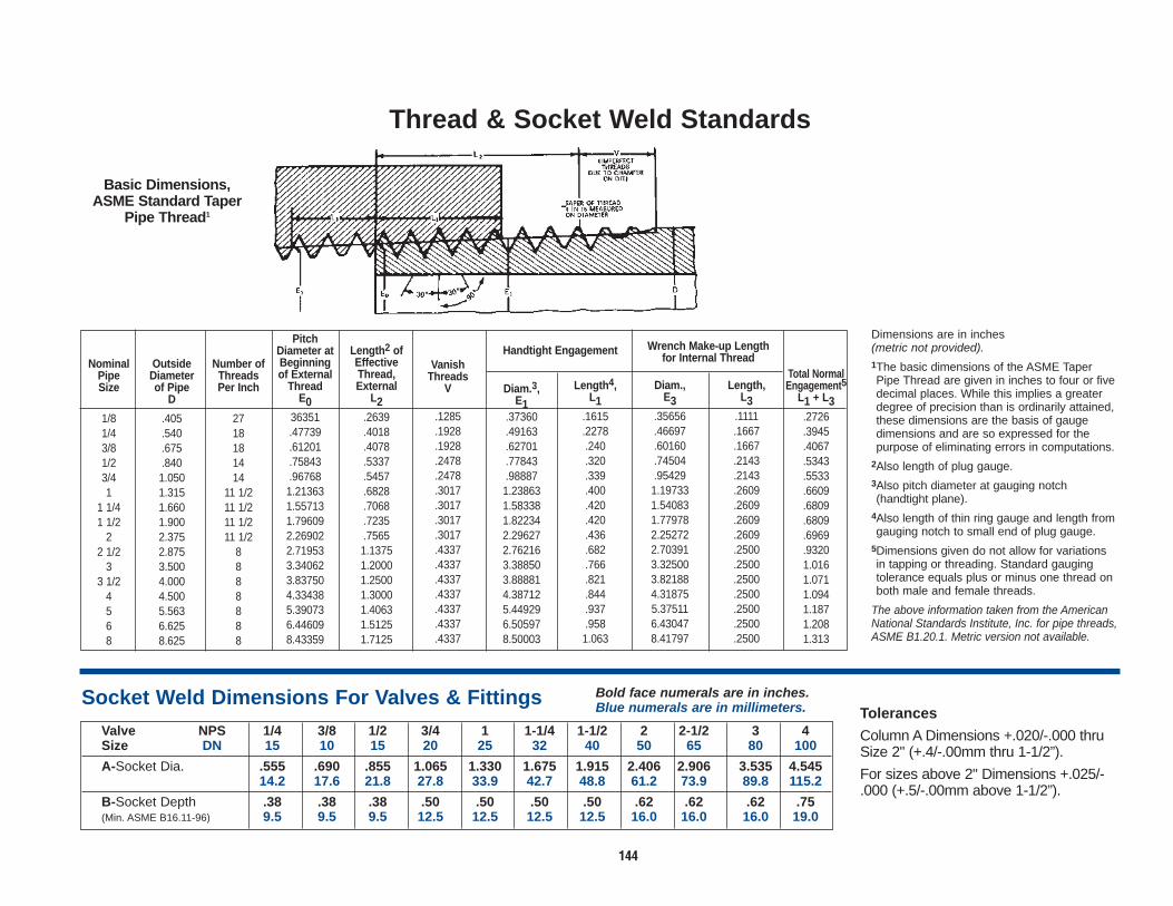
144
Thread & Socket Weld Standards
Basic Dimensions,ASME Standard Taper
Pipe Thread1
Socket Weld Dimensions For Valves & Fittings Bold face numerals are in inches.Blue numerals are in millimeters.
Valve NPS 1/4 3/8 1/2 3/4 1 1-1/4 1-1/2 2 2-1/2 3 4Size DN 15 10 15 20 25 32 40 50 65 80 100
A-Socket Dia. .555 .690 .855 1.065 1.330 1.675 1.915 2.406 2.906 3.535 4.54514.2 17.6 21.8 27.8 33.9 42.7 48.8 61.2 73.9 89.8 115.2
B-Socket Depth .38 .38 .38 .50 .50 .50 .50 .62 .62 .62 .75(Min. ASME B16.11-96) 9.5 9.5 9.5 12.5 12.5 12.5 12.5 16.0 16.0 16.0 19.0
NominalPipeSize
1/81/43/81/23/41
1 1/41 1/2
22 1/2
33 1/2
4568
OutsideDiameterof Pipe
D
.405
.540
.675
.8401.0501.3151.6601.9002.3752.8753.5004.0004.5005.5636.6258.625
Number ofThreadsPer Inch
2718181414
11 1/211 1/211 1/211 1/2
8888888
PitchDiameter atBeginningof External
ThreadE0
36351.47739.61201.75843.967681.213631.557131.796092.269022.719533.340623.837504.334385.390736.446098.43359
Length2 ofEffectiveThread,External
L2.2639.4018.4078.5337.5457.6828.7068.7235.75651.13751.20001.25001.30001.40631.51251.7125
VanishThreads
V
.1285
.1928
.1928
.2478
.2478
.3017
.3017
.3017
.3017
.4337
.4337
.4337
.4337
.4337
.4337
.4337
Diam.3,E1
.37360
.49163
.62701
.77843
.988871.238631.583381.822342.296272.762163.388503.888814.387125.449296.505978.50003
Length4,L1
.1615
.2278.240.320.339.400.420.420.436.682.766.821.844.937.9581.063
Total NormalEngagement5
L1 + L3.2726.3945.4067.5343.5533.6609.6809.6809.6969.93201.0161.0711.0941.1871.2081.313
Diam.,E3
.35656
.46697
.60160
.74504
.954291.197331.540831.779782.252722.703913.325003.821884.318755.375116.430478.41797
Length,L3
.1111.1667.1667.2143.2143.2609.2609.2609.2609.2500.2500.2500.2500.2500.2500.2500
Dimensions are in inches (metric not provided).1The basic dimensions of the ASME TaperPipe Thread are given in inches to four or fivedecimal places. While this implies a greaterdegree of precision than is ordinarily attained,these dimensions are the basis of gaugedimensions and are so expressed for thepurpose of eliminating errors in computations.
2Also length of plug gauge.3Also pitch diameter at gauging notch(handtight plane).
4Also length of thin ring gauge and length fromgauging notch to small end of plug gauge.
5Dimensions given do not allow for variationsin tapping or threading. Standard gaugingtolerance equals plus or minus one thread onboth male and female threads.
The above information taken from the AmericanNational Standards Institute, Inc. for pipe threads,ASME B1.20.1. Metric version not available.
Handtight Engagement Wrench Make-up Lengthfor Internal Thread
Tolerances
Column A Dimensions +.020/-.000 thruSize 2" (+.4/-.00mm thru 1-1/2”).
For sizes above 2" Dimensions +.025/-.000 (+.5/-.00mm above 1-1/2”).

145
Dimensional Data for Standard & Schedule Pipe – Carbon Steel PipeNPS 1/8 1/4 3/8 1/2 3/4 1 1-1/4 1-1/2 2 2-1/2 3 3-1/2 4 5 6 8 10 12
PIPE DN 6 8 10 15 20 25 32 40 50 65 80 95 100 125 150 200 250 300Outside Dia. .405 .540 .675 .840 1.050 1.315 1.660 1.900 2.375 2.875 3.500 4.000 4.500 5.563 6.625 8.625 10.750 12.750
10.3 13.7 17.1 21.3 26.7 33.4 42.2 48.3 60.3 73.0 88.9 101.6 114.3 141.3 168.3 219.1 273.0 323.8Inside Dia. .269 .364 .493 .622 .824 1.049 1.380 1.610 2.067 2.469 3.068 3.548 4.026 5.047 6.065 7.981 10.020 12.000
6.8 9.2 12.5 15.8 20.9 26.6 35.1 40.9 52.5 62.7 77.9 90.1 102 128 154 203 255 305Standard Wall Thick. .068 .088 .091 .109 .113 .133 .140 .145 .154 .203 .216 .226 .237 .258 .280 .322 .365 .375
1.73 2.24 2.31 2.77 2.87 3.38 3.56 3.68 3.91 5.16 5.49 5.74 6.02 6.55 7.11 8.18 9.27 9.53Wt. Per Ft. .24 .42 .57 .85 1.13 1.68 2.27 2.72 3.65 5.79 7.58 9.11 10.79 14.62 18.97 28.55 40.48 49.56
.37 .63 .84 1.27 1.69 2.50 3.39 4.05 5.44 8.63 11.29 13.57 16.07 21.77 28.26 42.55 60.31 73.88Inside Dia. .215 .302 .423 .546 .742 .957 1.278 1.50 1.939 2.323 2.900 3.364 3.826 4.813 5.761 7.625 9.750 11.750
Extra 5.4 7.7 10.7 13.9 18.8 24.3 32.5 38.1 49.2 59.0 73.7 85.4 97.2 122 146 194 248 298Heavy Wall Thick. .095 .119 .126 .147 .154 .179 .191 .200 .218 .276 .300 .318 .337 .375 .432 .500 .500 .500
2.41 3.02 3.20 3.73 3.91 4.55 4.85 5.08 5.54 7.01 7.62 8.08 8.56 9.53 10.97 12.70 12.70 12.70Wt. Per Ft. .31 .54 .74 1.09 1.47 2.17 3.00 3.63 5.02 7.66 10.25 12.50 14.98 20.78 28.57 43.39 54.74 65.42
.47 .80 1.10 1.62 2.20 3.24 4.47 5.41 7.48 11.41 15.27 18.63 22.32 30.97 42.56 64.64 81.55 97.46Inside Dia. .252 .434 .599 .896 1.100 1.503 1.771 2.300 3.152 4.063 4.897 6.875
Double 6.4 11.0 15.2 22.8 27.9 38.2 5.0 58.4 80.1 103 124 175Extra Wall Thick. .294 .308 .358 .382 .400 .436 .552 .600 .674 .750 .864 .875Heavy 7.47 7.82 9.09 9.70 10.15 11.07 13.69 15.24 17.12 19.05 21.95 22.23
Wt. Per Ft. 1.71 2.44 3.66 5.21 6.41 9.03 13.69 18.58 27.54 38.55 53.16 72.42.55 3.64 5.45 7.77 9.56 13.44 20.39 27.68 41.03 57.43 79.22 107.92
Inside Dia.Schedule Wall Thick.
10 Wt. Per Ft.Inside Dia. 8.125 10.250 12.250
206 .260 311Schedule Wall Thick. .250 .250 .250
20 6.35 6.35 6.35Wt. Per Ft. 22.36 28.04 33.38
33.31 41.77 49.73Inside Dia. 8.071 10.136 12.090
205 257 307Schedule Wall Thick. .277 .307 *.300
30 7.04 7.80 8.38Wt. Per Ft. 24.70 34.24 43.77
36.81 51.03 65.20Inside Dia. .269 .364 .493 .622 .824 1.049 1.380 1.610 2.067 2.469 3.068 3.548 4.026 5.047 6.065 7.981 10.020 11.938
6.8 9.2 12.5 15.8 20.9 26.6 35.1 40.9 52.5 62.7 77.9 90.1 102 128 154 203 255 303Schedule Wall Thick. .068 .088 .091 .109 .113 .133 .140 .145 .154 .203 .216 .226 .237 .258 .280 .322 .365 .406
40 1.73 2.24 2.31 2.77 2.87 3.38 3.56 3.68 3.91 5.16 5.49 5.74 6.02 6.55 7.11 8.18 9.27 10.32Wt.PerFt. .24 42 .57 .85 1.13 1.68 2.27 2.72 3.65 5.79 7.58 9.11 10.79 14.62 18.97 28.55 40.48 53.52
.37 63 .84 1.27 1.69 2.50 3.39 4.05 5.44 8.63 11.29 13.57 16.07 21.77 28.26 42.55 60.31 79.73Inside Dia. 7.813 9.750 11.626
198 248 295Schedule Wall Thick. .406 +.500 .562
60 10.31 12.70 14.27Wt. Per Ft. 35.64 54.74 73.15
53.08 81.55 108.96Inside Dia. .215 .302 .423 .546 .742 .957 1.278 1.50 1.939 2.323 2.900 3.364 3.826 4.813 5.761 7.625 9.564 11.376
5.5 7.7 10.7 13.9 18.8 24.3 32.5 38.1 49.3 59.0 73.7 85.4 97.2 122 146 194 243 289Schedule Wall Thick. .095 .119 .126 .147 .154 .179 .191 .200 .218 .276 .300 .318 .337 .375 .432 .500 .594 .688
80 2.41 3.02 3.20 3.73 3.91 4.55 4.85 5.08 5.54 7.01 7.62 8.08 8.56 9.53 10.97 12.70 15.02 17.48Wt. Per Ft. .31 .54 .74 1.09 1.47 2.17 3.00 3.63 5.02 7.66 10.25 12.51 14.98 20.78 28.57 43.39 64.43 88.63
.47 .80 1.10 1.62 2.20 3.24 4.47 5.41 7.48 11.41 15.27 18.63 22.32 30.97 42.56 64.64 96.01 132.08Inside Dia. 7.439 9.314 11.064
189 237 281Schedule Wall Thick. .594 .719 .844
100 1 5.09 18.26 21.44Wt. Per Ft. ~50.95 77.03 107.32
75.92 114.75 159.91Inside Dia. 3.624 4.563 5.501 7.189 9.064 10.75
92.0 116 140 183 230 273Schedule Wall Thick. .438 .500 .562 .719 .844 1.0000
120 11.13 12.70 14.27 18.26 21.44 25.40Wt. Per Ft. 19.00 27.04 36.39 60.71 89.24 125.49
28.32 40.28 54.20 90.44 133.06 186.97Inside Dia. 7.001 8.750 10.75
179 222 267Schedule Wall Thick. .812 1.000 1.125
140 20.62 25.40 28.58Wt. Per Ft. 67.76 104.13 139.67
100.92 155.15 208.14Inside Dia. .466 ,614 .815 1.160 1.338 1.689 2.125 2.624 3.438 4.313 5.189 6.813 8.500 10.126
11.8 15.6 20.7 29.5 34.0 42.9 54 0 66.6 87.3 110 132 173 216 257Schedule Wall Thick. .188 .219 .250 .250 .281 .344 375 .438 .531 .625 .719 .906 1.125 1.312
160 4.78 5.56 6.35 6.35 7.14 8.74 9.53 11.13 13.49 15.88 18.26 23.01 28.58 33.’Wt. Per Ft. 1.31 1 94 2.84 3.76 4.86 7.46 10.01 14.32 22.51 32.96 45.35 74.69 115.64 160.27
1.95 2.90 4.24 5.61 7.25 11.11 14.92 21.35 33.54 49.11 67.56 111.27 177.33 238.76
Bold face numerals are in inches and pounds. Blue numerals are in millimeters and kilograms.
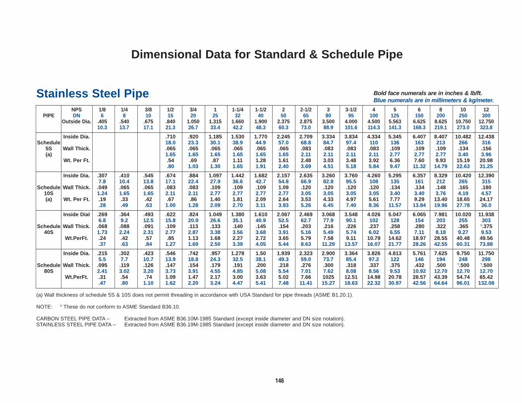
146
Dimensional Data for Standard & Schedule Pipe
(a) Wall thickness of schedule 5S & 10S does not permit threading in accordance with USA Standard for pipe threads (ASME B1.20.1).
NOTE: ❒ These do not conform to ASME Standard B36.10.
CARBON STEEL PIPE DATA – Extracted from ASME B36.10M-1985 Standard (except inside diameter and DN size notation).STAINLESS STEEL PIPE DATA – Extracted from ASME B36.19M-1985 Standard (except inside diameter and DN size notation).
Stainless Steel Pipe Bold face numerals are in inches & lb/ft.Blue numerals are in millimeters & kg/meter.
NPS 1/8 1/4 3/8 1/2 3/4 1 1-1/4 1-1/2 2 2-1/2 3 3-1/2 4 5 6 8 10 12PIPE DN 6 8 10 15 20 25 32 40 50 65 80 95 100 125 150 200 250 300
Outside Dia. .405 .540 .675 .840 1.050 1.315 1.660 1.900 2.375 2.875 3.500 4.000 4.500 5.563 6.625 8.625 10.750 12.75010.3 13.7 17.1 21.3 26.7 33.4 42.2 48.3 60.3 73.0 88.9 101.6 114.3 141.3 168.3 219.1 273.0 323.8
Inside Dia. .710 .920 1.185 1.530 1.770 2.245 2.709 3.334 3.834 4.334 5.345 6.407 8.407 10.482 12.438Schedule 18.0 23.3 30.1 38.9 44.9 57.0 68.8 84.7 97.4 110 136 163 213 266 316
5S Wall Thick. .065 .065 .065 .065 .065 .065 .083 .083 .083 .083 .109 .109 .109 .134 .156(a) 1.65 1.65 1.65 1.65 1.65 1.65 2.11 2.11 2.11 2.11 2.77 2.77 2.77 3.40 3.96
Wt. Per Ft. .54 .69 .87 1.11 1.28 1.61 2.48 3.03 3.48 3.92 6.36 7.60 9.93 15.19 20.98.80 1.03 1.30 1.65 1.91 2.40 3.69 4.51 5.18 5.84 9.47 11.32 14.79 22.63 31.25
Inside Dia. .307 .410 .545 .674 .884 1.097 1.442 1.682 2.157 2.635 3.260 3.760 4.260 5.295 6.357 8.329 10.420 12.3907.8 10.4 13.8 17.1 22.4 27.9 36.6 42.7 54.8 66.9 82.8 95.5 108 135 161 212 265 315
Schedule Wall Thick. .049 .065 .065 .083 .083 .109 .109 .109 1.09 .120 .120 .120 .120 .134 .134 .148 .165 .18010S 1.24 1.65 1.65 2.11 2.11 2.77 2.77 2.77 2.77 3.05 3.05 3.05 3.05 3.40 3.40 3.76 4.19 4.57(a) Wt. Per Ft. .19 .33 .42 .67 .86 1.40 1.81 2.09 2.64 3.53 4.33 4.97 5.61 7.77 9.29 13.40 18.65 24.17
.28 .49 .63 1.00 1.28 2.09 2.70 3.11 3.93 5.26 6.45 7.40 8.36 11.57 13.84 19.96 27.78 36.0
Inside Dial .269 .364 .493 .622 .824 1.049 1.380 1.610 2.067 2.469 3.068 3.548 4.026 5.047 6.065 7.981 10.020 11.9386.8 9.2 12.5 15.8 20.9 26.6 35.1 40.9 52.5 62.7 77.9 90.1 102 128 154 203 255 303
Schedule Wall Thick. .068 .088 .091 .109 .113 .133 .140 .145 .154 .203 .216 .226 .237 .258 .280 .322 .365 ❒.37540S 1.73 2.24 2.31 2.77 2.87 3.38 3.56 3.68 3.91 5.16 5.49 5.74 6.02 6.55 7.11 8.18 9.27 9.53
Wt.PerFt. .24 .42 .57 .85 1.13 1.68 2.27 2.72 3.65 5.79 7.58 9.11 10.79 14.62 18.97 28.55 40.48 49.56.37 .63 .84 1.27 1.69 2.50 3.39 4.05 5.44 8.63 11.29 13.57 16.07 21.77 28.26 42.55 60.31 73.88
Inside Dia. .215 .302 .423 .546 .742 .957 1.278 1.50 1.939 2.323 2.900 3.364 3.826 4.813 5.761 7.625 9.750 11.7505.5 7.7 10.7 13.9 18.8 24.3 32.5 38.1 49.3 59.0 73.7 85.4 97.2 122 146 194 248 298
Schedule Wall Thick. .095 .119 .126 .147 .154 .179 .191 .200 .218 .276 .300 .318 .337 .375 .432 .500 ❒.500 ❒.50080S 2.41 3.02 3.20 3.73 3.91 4.55 4.85 5.08 5.54 7.01 7.62 8.08 8.56 9.53 10.92 12.70 12.70 12.70
Wt.PerFt. .31 .54 .74 1.09 1.47 2.17 3.00 3.63 5.02 7.66 1025 12.51 14.98 20.78 28.57 43.39 54.74 65.42.47 .80 1.10 1.62 2.20 3.24 4.47 5.41 7.48 11.41 15.27 18.63 22.32 30.97 42.56 64.64 96.01 132.08

147
Engineering Information (English Units Only)
Check Valve Cracking/Opening Pressures
(701,15701, 573, 583, 593, etc.) 1/2"-.61 psi 3/4"-.61 psi 1" - .52 psi
1 1/4" -.57 psi 1 1/2" - .57 psi
2" - .58 psiAll spring loaded Check valves have
cracking pressures of 10-12 psi.
Handwheel Max. Closing Torques(Typical in Ft-lbs)
Class 800 Reduced Port Gate1/4", 3/8" - 8 ft-lbs 1/2", 3/4" - 15 ft-lbs
1" - 20 ft-lbs 1 1/4", 1 1/2" - 50 ft-lbs
2" - 70 ft-lbs Class 800 Full Port Gate
1/2" -15 ft-lbs 3/4" - 20 ft-lbs 1" - 40 ft-lbs
1 1/4" - 50 ft-lbs 1 1/2" - 70 ft-lbs
2" - 100 ft-lbs
Handwheel Max. Closing Torques(Typical in Ft-lbs)
Class 800 Reduced Port Globe
1/2" - 15 ft-lbs3/4" - 15 ft-lbs 1" - 30 ft-lbs
1 1/2" - 40 ft-lbs 2" - 75 ft-lbs
Class 800 Full Port Globe
1/2" - 15 ft-lbs 3/4" - 30 ft-lbs 1" - 40 ft-lbs
1 1/2" - 75 ft-lbs 2" - 125 ft-lbs
Note: Reduce above values by 25% to 30% if any type lubrication is used on bolting.
Maximum Packing Gland Bolting Torque
1/2
3/4
1
1 1/4
1 1/2
2
2 1/2
3
4
1.8 ft-lbs
1.8 ft-lbs
3.7 ft-lbs
4.0 ft-lbs
4.0 ft-lbs
7.5 ft-lbs
8.5 ft-lbs
8.5 ft-lbs
12.0 ft-lbs
1.8 ft-lbs
3.7 ft-lbs
4.0 ft-lbs
7.5 ft-lbs
8.5 ft-lbs
4.2 ft-lbs
4.2 ft-lbs
7.5 ft-lbs
13.9 ft-lbs
13.9 ft-lbs
15.9 ft-lbs
4.2 ft-lbs
7.5 ft-lbs
13.9 ft-lbs
13.9 ft-lbs
15.9 ft-lbs
300, 600 &800 Conv.
Port
Size Class 600 &800 Full
Port
Class 1500 Class 1500Full Port
Recommended Maximum Bonnet Bolt Torques (Dry, Unlubricated Values)
5/16"
3/8"
7/16"
1/2"
9/16"
5/8"
3/4"
7/8"
1"
25
40
50
85
144
125
175
530
795
22
36
45
75
130
115
156
480
710
BoltDiameter
Torque (ft-lbs)B7 & B16
B8M

148
1 to 20 21 to 40 41 to 60 61 to 80 81 to 100
Weight Conversion
Pressure Conversion
Lbs. Lbs. Lbs. Lbs. Lbs.per per per per per
Bar Sq. Bar Sq. Bar Sq. Bar Sq. Bar Sq.Inch Inch Inch Inch Inch
1 14.5 21 304.5 41 594.5 61 884.5 81 1174.52 29.0 22 319.0 42 609.0 62 899.0 82 1189.03 43.5 23 333.5 43 623.5 63 913.5 83 1203 54 58.0 24 348.0 44 638.0 64 928.0 84 1218 05 72.5 25 362.5 45 652.5 65 942.5 85 1232.5
6 87.0 26 377.0 46 667.0 66 957.0 86 1247.07 101.5 27 391.5 47 681.5 67 971.5 87 1261.58 116.0 28 406.0 48 696.0 68 986.0 88 1276.09 130.5 29 420.5 49 710.5 69 1000.5 89 1290.510 145.0 30 435.0 50 725.0 70 1015.0 90 1305.0
11 159.5 31 449.5 51 739.5 71 1029.5 91 1319.512 174.0 32 464.0 52 754.0 72 1044.0 92 1334.013 188.5 33 478.5 53 768.5 73 1058.5 83 1348.514 203.0 34 493.0 54 783.0 74 1073.0 94 1363.015 217.5 35 507.s 55 797 s 75 1087.5 95 1377.5
16 232.0 36 522.0 56 812.0 76 1102.0 96 1392.017 246.5 37 536.5 57 826.5 77 1116.5 97 1406.518 261.0 38 551.0 58 841.0 78 1131.0 98 1421.019 275.5 39 565.5 59 855.5 79 1145.5 39 1435.520 290.0 40 580.0 60 870.0 80 1160.0 100 1450.0
Pounds to Kilograms(1 pound = 0.4536 kilogram)
Pounds 0 1 2 3 4 5 6 7 8 9
0 0.00 0.45 0.91 1.36 1.81 2.27 2.72 3.18 3.63 4.08
10 4.54 4.99 5.44 5.90 6.35 6.80 7.26 7.71 8.16 8.62
20 9.07 9.53 9.98 10.43 10.89 11.34 11.79 12.25 12.70 13.15
30 13.61 14.06 14.52 14.97 15.42 15.88 16.33 16.78 17.24 17.69
40 18.14 18.60 19.05 19.50 19.96 20.41 20.87 21.32 21.77 22.23
50 22.68 23.13 23.59 24.04 24.49 24.95 25.40 25.86 26.31 26.76
60 27.22 27.67 28.12 28.58 29.03 29.48 29.94 30.39 30.84 31.30
70 31.75 32.21 32.66 33.11 33.57 34.02 34.47 34.93 35.38 35.83
80 36.29 36.74 37.20 37.65 38.10 38.56 39.01 39.46 39.92 40.37
90 40.82 41.28 41.73 42.18 42.64 43.09 43.55 44.00 44.45 44.91
Kilograms to Pounds (1 kilogram = 2.2046 pounds)
Kilograms 0 1 2 3 4 5 6 7 8 9
0 0.00 2.20 4.41 6.61 8.82 11.02 13.23 15.43 17.64 19.84
10 22.05 24.25 26.46 28.66 30.86 33.07 35.27 37.48 39.68 41.89
20 44.09 46.30 48.50 50.71 52.91 55.12 57.32 59.52 61.73 63.93
30 66.14 68.34 70.55 72.75 74.96 77.16 79.37 81.57 83.77 85.98
40 88.18 90.39 92.59 94.80 97.00 99.21 101.41 103.62 105.82 108.03
50 110.23 112.43 114.64 116.84 119.05 121.25 123.46 125.66 127.87 130.07
60 132.28 134.48 136.69 138.89 141.09 143.30 145.50 147.71 149.91 152.12
70 154.32 156.53 158.73 160.94 163.14 165.35 167.55 169.75 171.96 174.16
80 176.37 178.57 180.87 182.98 185.19 187.39 189.60 191.80 194.00 196.21
90 198.41 200.62 202.82 205.03 207.23 209.44 211.64 213.85 216.05 218.26
Bar to Pounds per Square Inch (1 Bar = 105 Pa = 14.5 pounds per square inch)

149
-459.4° to 0° 1° to 60° 61° to 290° 300° to 890° 900° to 3000°CEL. CEL. CEL. CEL. CEL.
C OR F C OR F C OR F C OR F C OR FFAH. FAH. FAH. FAH. FAH.
–273 –459.4 –17.2 1 33.8 16.1 61 141.8 149 300 572 482 900 1652–268 –450 –16.7 2 35.6 16.7 62 143.6 154 310 590 488 910 1670–262 –440 –16.1 3 37.4 17.2 63 145.4 160 320 608 493 920 1688–257 –430 –15.6 4 39.2 17.8 64 147.2 166 330 626 499 930 1706–251 –420 –15.0 5 41.0 18.3 65 149.0 171 340 644 504 940 1724–246 –410 –14.4 6 42.8 18.9 66 150.8 177 350 662 510 950 1742–240 –400 –13.9 7 44.6 19.4 67 152.6 182 360 680 516 960 1760–234 –390 –13.3 8 46.4 20.0 68 154.4 188 370 698 521 970 1778–229 –380 –12.8 9 48.2 20.6 69 156.2 193 380 716 527 980 1796–223 –370 –12.2 10 50.0 21.1 70 158.0 199 390 734 532 990 1814–218 –360 –11.7 11 51.8 21.7 71 159.8 204 400 752 538 1000 1832–212 –350 –11.1 12 53.6 22.2 72 161.6 210 410 770 549 1020 1868–207 –340 –10.6 13 55.4 22.8 73 163.4 215 420 788 560 1040 1904–201 –330 –10.0 14 57.2 23.3 74 165.2 221 430 806 571 1070 1940–196 –320 –9.4 15 59.0 23.9 75 167.0 227 440 824 582 1080 1976–190 –310 –8.9 16 60.8 24.4 76 168.8 232 450 842 593 1100 2012–184 –300 –8.3 17 62.6 25.0 77 170.6 238 460 860 604 1120 2048–179 –290 –7.8 18 64.4 25.6 78 172.4 243 470 878 616 1140 2084–173 –280 –7.2 19 66.2 26.1 79 174.2 249 480 896 627 1160 2120–169 –273 –459.4 –6.7 20 68.0 26.7 80 176.0 254 490 914 638 1180 2156–168 –270 –454 –6.1 21 69.8 27.2 81 177.8 260 500 932 649 1200 2192–162 –260 –436 –5.6 22 71.6 27.8 82 179.6 266 510 950 660 1220 2228–157 –250 –418 –5.0 23 73.4 28.3 83 181.4 271 520 968 671 1240 2264–151 –240 –400 –4.4 24 75.2 28.9 84 183.2 277 530 986 682 1260 2300–146 –230 –382 –3.9 25 77.0 29.4 85 185.0 282 540 1004 693 1280 2336–140 –220 –364 –3.3 26 78.8 30.0 86 186.8 288 550 1022 704 1300 2372–134 –210 –346 –2.8 27 80.6 30.6 87 188.6 293 560 1040 732 1350 2462–129 –200 –328 –2.2 28 82.4 31.1 88 190.4 299 570 1058 760 1400 2552–123 –190 –310 –1.7 29 84.2 31.7 89 192.2 304 580 1076 788 1450 2642–118 –180 –292 –1.1 30 86.0 32.2 90 194.0 310 590 1094 816 1500 2732–112 –170 –274 –0.6 31 87.8 32.8 91 195.8 316 600 1112 843 1550 2822–107 –160 –256 0.0 32 79.6 33.3 92 197.6 321 610 1130 871 1600 2912–101 –150 –238 0.6 33 91.4 33.9 93 199.4 327 620 1148 899 1650 3002–96 –140 –220 1.1 34 93.2 34.4 94 201.2 332 630 1166 927 1700 3092–90 –130 –202 1.7 35 95.0 35.0 95 203.0 338 640 1184 954 1750 3182–84 –120 –184 2.2 36 96.8 35.6 96 204.8 343 650 1202 982 1800 3272–79 –110 –166 2.8 37 98.6 36.1 97 206.6 349 660 1220 1010 1850 3362–73 –100 –148 3.3 38 100.4 36.7 98 208.4 354 670 1238 1038 1900 3452–68 –90 –130 3.9 39 102.2 37.2 99 210.2 360 680 1256 1066 1950 3542–62 –80 –112 4.4 40 104.0 37.8 100 212.0 366 690 1274 1093 2000 3632–57 –70 –94 5.0 41 105.8 43 110 230 371 700 1292 1121 2050 3722–51 –60 –76 5.6 42 107.6 49 120 248 377 710 1310 1149 2100 3812–46 –50 –58 6.1 43 109.4 54 130 266 382 720 1328 1177 2150 3902–40 –40 –40 6.7 44 111.2 60 140 284 388 730 1346 1204 2200 3992–34 –30 –22 7.2 45 113.0 66 150 302 393 740 1364 1232 2250 4082–29 –20 –4 7.8 46 114.8 71 160 320 399 750 1382 1260 2300 4172–23 –10 14 8.3 47 116.6 77 170 338 404 760 1400 1288 2350 4262–17.8 0 32 8.9 48 118.4 82 180 356 410 770 1418 1316 2400 4352
9.4 49 120.2 88 190 374 416 780 1436 1343 2450 444210.0 50 122.0 93 200 392 421 790 1454 1371 2500 453210.6 51 123.8 99 210 410 427 800 1472 1399 2550 462211.1 52 125.6 100 212 413.6 432 810 1490 1427 2600 471211.7 53 127.4 104 220 428 438 820 1508 1454 2650 480212.2 54 129.2 110 230 446 443 830 1526 1482 2700 489212.8 55 131.0 116 240 464 449 840 1544 1510 2750 498213.3 56 132.8 121 250 482 454 850 1562 1538 2800 507213.9 57 134.6 127 260 500 460 860 1580 1566 2850 516214.4 58 136.4 132 270 518 466 870 1598 1593 2900 525215.0 59 138.2 138 280 536 471 880 1616 1621 2950 534215.6 60 140.0 143 290 554 477 890 1634 1649 3000 5432
Temperature ConversionCelsius (C) To Fahrenheit (F) — Fahrenheit (F) To Celcius
Locate temperature in middle column. If in degrees Celsius, read Fahrenheit equivalent in right-hand column; if in degrees Fahrenheit, read Celsius equivalent in left-hand column.
F = C + 329—5
C = (F - 32)5—9Conversion Formulas

Flowserve Corporation has established industry leadership in the design and manufacture of its products. When properly selected, this Flowserve product is designed to perform its intended function safely during its useful life.However, the purchaser or user of Flowserve products should be aware that Flowserve products might be used in numerous applications under a wide variety of industrial service conditions. Although Flowserve can (and often does)provide general guidelines, it cannot provide specific data and warnings for all possible applications. The purchaser/user must therefore assume the ultimate responsibility for the proper sizing and selection, installation, operation,and maintenance of Flowserve products. The purchaser/user should read and understand the Installation Operation Maintenance (IOM) instructions included with the product, and train its employees and contractors in the safe use ofFlowserve products in connection with the specific application.
While the information and specifications contained in this literature are believed to be accurate, they are supplied for informative purposes only and should not be considered certified or as a guarantee of satisfactory results byreliance thereon. Nothing contained herein is to be construed as a warranty or guarantee, express or implied, regarding any matter with respect to this product. Because Flowserve is continually improving and upgrading its productdesign, the specifications, dimensions and information contained herein are subject to change without notice. Should any question arise concerning these provisions, the purchaser/user should contact Flowserve Corporation at anyone of its worldwide operations or offices.
Vogt Valves1511 Jefferson StreetSulphur Springs, TX 75482
Toll-Free Telephone Service1-800-225-6989
US Sales OfficesPhone: 903-885-3151Fax: 903-439-3386
Visit Our Websitewww.flowserve.com
© 2004 Flowserve Corporation, Irving, Texas, USA. Flowserve and Vogt Valves are registered trademarks of Flowserve Corporation. FCD VVACT0000-01 (Replaces VV200) Printed in USA
FLOWSERVE CORPORATIONVogt Valves 1511 Jefferson StreetSulphur Springs, TX 75482Phone: 903-885-3151Fax: 903-439-3386
For more information about Flowserve Corporation, visit www.flowserve.com or call USA 1-800-225-6989.
Flow Control
Vogt Valves