
VNR VIGNANA JYOTHI INSTITUTE OF ENGINEERING & · PDF file · 2017-03-12... Ist...
62
1 VNR VIGNANA JYOTHI INSTITUTE OF ENGINEERING & TECHNOLOGY (Autonomous) DEPARTMENT OF MECHANICAL ENGINEERING III B. Tech, I st Semester (Mechanical Engineering) Subject : DYNAMICS OF MACHINERY Subject Code : 13MED010 Academic Year : 2016 – 17 Number of working days : 90 Number of Hours / week : 4 + 1 Total number of periods planned: 70 Name of the Faculty Member: K.NAGENDRA BABU/H NARESH Course Objectives: Study the construction methods like Klien’s, velocity polygons, acceleration diagrams etc for drawing various mechanisms. Identify the significance of the principles of equilibrium, super position, virtual work& D’Alembert’s principle. Familiarize with the methods of static &dynamic stability. Course Outcomes (COs): Upon completion of this course, students should be able to: CO-1: Show the engineering applications involving the selection and design of machine components with respect to the forces developed. CO-2: Check whether the proposed design is satisfactory. CO-3: Analyze and design flywheels, governors and gyroscopes to withstand forces. UNIT : I Syllabus: PRECESSION: Gyroscopes, effect of precessional motion on the stability of moving vehicles such as motor car, motor cycle, aeroplanes and ships STATIC FORCE ANALYSIS : Static force analysis of planar mechanisms DYNAMIC FORCE ANALYSIS: Dynamic force analysis of planar mechanisms Learning Objectives: After completion of the unit, the student must able to: 1) Define precessional motion and gyroscopic effect on vehicles 2) Describe the application of gyroscopic principles to motor car, motor cycle, aeroplanes and ships 3) Identify the direction of motion due to gyroscopic effect 4) Define static force analysis and dynamic force analysis 5) Draw the freebody diagrams and identify the forces acting by graphical methods 6) Solve the magnitudes and determine the direction of forces transmitted 7) Describe the effect of inertia forces on the body 8) Solve the problems for determining the torque.
Transcript of VNR VIGNANA JYOTHI INSTITUTE OF ENGINEERING & · PDF file · 2017-03-12... Ist...

1
VNR VIGNANA JYOTHI INSTITUTE OF ENGINEERING & TECHNOLOGY
(Autonomous)
DEPARTMENT OF MECHANICAL ENGINEERING
III B. Tech, Ist Semester (Mechanical Engineering)
Subject : DYNAMICS OF MACHINERY
Subject Code : 13MED010
Academic Year : 2016 – 17
Number of working days : 90
Number of Hours / week : 4 + 1
Total number of periods planned: 70
Name of the Faculty Member: K.NAGENDRA BABU/H NARESH
Course Objectives:
Study the construction methods like Klien’s, velocity polygons, acceleration diagrams
etc for drawing various mechanisms.
Identify the significance of the principles of equilibrium, super position, virtual
work& D’Alembert’s principle.
Familiarize with the methods of static &dynamic stability.
Course Outcomes (COs): Upon completion of this course, students should be able to:
CO-1: Show the engineering applications involving the selection and design of
machine components with respect to the forces developed.
CO-2: Check whether the proposed design is satisfactory.
CO-3: Analyze and design flywheels, governors and gyroscopes to withstand forces.
UNIT : I
Syllabus:
PRECESSION: Gyroscopes, effect of precessional motion on the stability of moving
vehicles such as motor car, motor cycle, aeroplanes and ships
STATIC FORCE ANALYSIS : Static force analysis of planar mechanisms
DYNAMIC FORCE ANALYSIS: Dynamic force analysis of planar mechanisms
Learning Objectives: After completion of the unit, the student must able to:
1) Define precessional motion and gyroscopic effect on vehicles
2) Describe the application of gyroscopic principles to motor car, motor cycle, aeroplanes and
ships
3) Identify the direction of motion due to gyroscopic effect
4) Define static force analysis and dynamic force analysis
5) Draw the freebody diagrams and identify the forces acting by graphical methods
6) Solve the magnitudes and determine the direction of forces transmitted
7) Describe the effect of inertia forces on the body
8) Solve the problems for determining the torque.

2
Lecture Plan
S.No. Description of Topic No. of Hrs. Method of Teaching
1. Introduction-Gyroscopes, effect of
precessional motion on the stability of
moving vehicles
1st & 2
nd hour PPT + Video
2. effect of precessional motion on the stability
of moving vehicles -motor car
3rd
& 4th
hour Black board + Video
3. effect of precessional motion on the stability
of moving vehicles -motor cycle
5th
hour Black board
4. effect of precessional motion on the stability
of moving vehicles – aeroplanes
6th
hour Black board + Video
5. effect of precessional motion on the stability
of moving vehicles - ships.
7th
hour Black board
6. Introduction-free body diagrams 8th
hour Black board + PPT
7. conditions of equilibrium-two and three force
members
9th
& 10th
hour Black board + Video
8. Inertia forces and D’Alembert’s principle 11th
hour Black board
9. planar rotation about a fixed centre 12th
hours Black board + Video
10. Three position synthesis- four position
synthesis
13th
& 14th
hour Black board
11. precision positions-structural error
Chebyshev’s spacing, Freudenstein’s
Equation, problems.
15th
,16th
&17th
hour
Black board
Assignment – 1
(1)A disc with radius of gyration 60 mm and a mass of 4 Kg is mounted centrally on a
horizontal axle of length 800 mm between bearings. It spins about the axle at 800 rpm
counter clockwise when viewed from the right hand side bearing. The axle precesses about a
vertical axis at 50 rpm in the clockwise direction when viewed from above. Determine the
resultant reaction at each bearing due to the mass and gyroscopic effect.
(2)An aircraft is flying at 300 Km/ hr .It turns towards left completing 1 /4 th of a circle of 80
m radius .The mass of the engine and the other parts is 520 Kg with radius of gyration of 345
mm. The engine is running at 2400 rpm clockwise when seen from rear. Calculate the
gyroscopic couple and its effect.
(3)The turbine rotor of a ship has a mass of 2.2 tonnes and rotates at 1800 rpm clockwise
when viewed from the aft. The radius of gyration of the rotor is 320 mm. Determine the
gyroscopic couple and its effect when
(a) Ship turns right at a radius of 250 mm with a speed of 25 Km/hr
(b)The ship pitches with the bow rising at an angular velocity of 0.8 rad/sec
(c)Ship rolls at an angular velocity of 0.1 rad/sec
(4)A four wheeled motor car of mass 2 tonnes has a height of C.G 600 mm above the ground
level. The engine parts and transmission are equivalent to a flywheel of 80 Kg with a radius
of gyration of 150 mm and their coincides with the longitudinal axis of the vehicle .The car
negotiates a curve of 60 m radius at 72 Km/hr with the overall gear ratio of 4.The radius of
the road wheel is 300 mm and its moment of inertia is 3 Kgm2.Assume wheel track as 1.5 m.
Determine the reaction at each road wheel

3
(5)Each wheel of a motor cycle is 500 mm diameter and has a M.I of 1.1Kgm2. The total
mass of the motor cycle with its rider is 220 Kg and the center of mass is 500 mm above the
ground level. The M.I of the rotating parts of the engine is 0.25 Kg m2.The engine speed is 4
times the speed of the wheels and in the same sense .Determine the angle of heel necessary
when the motor cycle takes a turn of 40 m radius at a speed of 50 Km/hr.
UNIT : II
Syllabus:
CLUTCHES: Friction clutches, Single disc or plate clutch, multiple disc clutch, cone clutch& centrifugal
clutch.
BRAKES AND DYNAMOMETERS: Simple block brakes, internal expanding brake, band brake of vehicle.
Dynamometers - absorption and transmission types- general description and method of
operation.
Learning Objectives: After completion of the unit, the student must able to:
1) Define the types of friction
2) Describe the effect of friction in engineering problems
3) Solve for efficiency and torque of a machine
4) Describe the effect of friction on bearings
5) define uniform wear and uniform pressure,
6) define boundary friction and film lubrication
7) Describe a brake and its importance in engg. applications
8) Solve for the torque transmitted
9) Determine the distance travelled by the vehicle before coming to rest
10) Solve for the calculation of power and torque transmitted
11) Define a clutch and calculate the various forces acting on the clutches
12) Define a brake and dynamometer
13) Calculate the braking torque in brakes and clutches
Lecture Plan
S.No. Description of Topic No. of Hrs. Method of Teaching
1. Introduction -Friction clutches 18th
hour PPT + Video
2. Single disc or plate clutch, multiple disc
clutch
19th
hours Black board
3. cone clutch& centrifugal clutch 20th
hour Black board + Video
4. Simple block brakes, internal expanding
brake
21th
hours Black board
5. band brake of vehicle 22th
& 23th
hours Black board
6. Dynamometers – absorption types 24rd&
25th
hour Black board + PPT
7. transmission types 226th
& 27th
hour Black board
8. general description and method of operation.
28th
,29th
& 30th
hour
Black board + Video

4
Assignment - 2
(1)An effort of 1500N is required to just move a certain body up an inclined plane of
150,force acting parallel to the plane.If the angle is increased to 180 ,the effort required is
2000N.Determine the weight of the body and the coefficient of friction.
(2)The mean diameter of the screw jack having a pitch of 10 mm is 50 mm.A load of 20kN is
lifted through a distance of 170 mm.Find the workdone in lifting the load and the efficiency
of the screw jack when
(a)The load rotates with the screw
(b)The load rests on the loose head which does not rotate with the screw The external
diameter and internal diameter of the bearing surface of loose head area 50 mm and 10 mm
respectivesly.Assume the coefficient of friction of the screw and the bearing surface as 0.1
(3)The mean diameter of whitworth bolt having V-threads is 20 mm.The pitch is 5 mm and
the included angle of the V-thread is550 .The bolt is tightened by s nut whose mean diameter
is 37.5 mm.The coefficient of friction for the nut and bolt is 0.1 and for the nut and bearing
surface is 0.2.Determine the force required at the end of a spanner of 0.4 m long when the
losd on the bolt is 60 kN.
(4)The thrust of a propeller shaft in a marine engine is taken up by a number of collars
integral with the shaft which is 300 mm in diameter.The thrust on the shaft is 20 x 104N and
speed is 90 rpm.Assume the intensity of pressure is uniform and equal to 0.3 MPa.Find the
external diameter of the collar and the number of collars required if the power lost in friction
is 20kW.Take μ
(5)A single plate clutch effective of both sides is required to transmit 25 kW at 3000
rpm.Determine the outer and inner radii of the friction surface if μ is 0.255,the ratio of radii is
1.25 and the maximum pressure is not to exceed 0.1 N/ mm2.Also determine the axial thrust
to be provided by the springs .Assume uniform wear theory.
(6)A cone clutch transmits 30kW at 600 rpm.The coefficient of friction is 0.23 and the
permissible intensity of pressure is 350kN/m2 .The semi cone angle is 12.50 .The outer
diameter is 300 mm .Assume uniform wear theory and find
(a) the inner diameter
(b)face width of the clutch
(c)force required to engage the clutch
(7) A band brake exerts a torque of 1500Nm.The drum is 50 mm wide and has a diameter of
500 mm. If the maximum pressure between the drum and the lining if 0.7 Mpa and μ=0.3 find
the angle of contact between the band and the drum.
(8) A band brake used for a winch is wound round a drum of 0.75 m diameter keyed to the
shaft .The two ends of the band are attached to the pins on the opposite sides of the fulcrum
of the brake lever at a distance of 25 mm and 100 mm from the fulcrum. The angle of lap is
2400 and μ=0.25.Find the torque which can be applied by the brake when a force of 500N is
applied to the lever at a distance of 1 m from the fulcrum with
the force acting downwards.

5
(9)In a band and block brake, the band is lined with 14 blocks each of which subtends an
angle of 20 0 at the drum Centre. One end of the band is attached to the fulcrum of the lever
and the other end to a pin 150 mm from the fulcrum to give a breading torque of 4000 Nm.
The diameter of the brake drum is 1 m and the coefficient of friction is 0.25.Determine the
force required at the end of the lever of length 1.5 m.
(10)A four wheeler of weight 3000N has its C.G 0.6 m above the ground level moves on a
level road with a speed of 36 km/hr. The wheel base is 2.4m and the C.G is 0.9 m in front of
the back axle and 1.5 m behind the front axle. Find the minimum distance in which the car
may be stopped
when
(a)the brakes are applied to the rear wheels
(b) the brakes are applied to the front wheels
(c) the brakes are applied to all the four wheels
The coefficient of friction between the tyre and the road surface is 0.5
(11) Describe with sketches the different types of dynamometers and calculate the power
transmitted in each case
UNIT : III
Syllabus:
TURNING MOMENT DIAGRAMS AND FLYWHEELS:
TURNING MOMENT: Inertia torque-angular velocity and acceleration of connecting rod, crank effort and torque
diagrams- Fluctuation of energy-design of flywheels.
GOVERNORS: Watt, Porter and Proell governors, Spring loaded governors- Hartnell and Hartung with
auxiliary springs, Sensitiveness, isochronism and hunting.
Learning Objectives: After completion of the unit, the student must able to:
1) Define turning moment and inertia torque
2) Compare the turning moment diagrams with the actual machines to predict the
Performance
3) Define fluctuation of energy, maximum fluctuation of energy and coefficient of fluctuation
Of energy
4) Describe the function of flywheel
5) Solve for the energy fluctuations in engine
6) Determine the dimensions of flywheel for safe design Compare the functions of governor
And flywheel
7) Regulate the speed of the engine
8) Solve for the equilibrium speed of the governor for stability
9) Define sensitiveness, isochronism and hunting
10) Describe the effect of controlling force in governors

6
Lecture Plan
S.No. Description of Topic No. of Hrs. Method of Teaching
1. Inertia torque-angular velocity 31st & 32
nd hour Black board + Video
2. acceleration of connecting rod 33rd
& 34th
hour Black board + Video
3. crank effort and torque diagrams 35th
& 36th
hour Black board + Video
4. Fluctuation of energy-design of flywheels 37th
& 38th
hour Black board + Video
5. Watt, Porter and Proell governors 39th
& 40th
hour Black board + Video
6. Spring loaded governors 41st & 42
nd hour Black board
7. Hartnell and Hartung with auxiliary springs 43rd
& 44th
hour PPT + Video
8. Sensitiveness, isochronism and hunting 45th
& 46th
hour Black board + Video
Assignment – 3
(1) An engine shaft runs at a mean speed of 5 rps . The torque required by the engine varies
uniformly from 500 Nm to 2500Nm while the shaft runs through 900, remains constant for
the next 1800, decreases uniformly to 500 Nm in 900 and remains constant for the next one
revolution. The whole cycle is repeated thereafter. The power is supplied by a constant torque
motor and the fluctuations of speed is limited to +/_ 3% of the mean speed. Determine (a)
power of the motor (b) M.I of the flywheel
(2) A single cylinder single acting four stroke gas engine develops 20kW at 300 rpm. The
work done by the gases during the expansion stroke is three times the wok done on the gases
during the compression stroke, the work done during the suction and exhaust strokes is
negligible .If the total fluctuation of speed is not to exceed +/_ 2% of the mean speed and the
turning moment diagram is assumed to be triangular in shape ,find the moment of inertia of
the flywheel.
(3) In a turning moment diagram for a multi-cylinder engine taken in order are as follows
-30, +400, -280, +275, -320, +290, -340, +375, -370mm2.The scales for the T.M diagram
are1 mm = 650 Nm on y-axis , 1mm =4.50 on x-axis. The mean speed of the engine is
500rpm and the fluctuation of speed is not to exceed 2% of the mean speed .Determine
(a)diameter of the flywheel
(b) cross-section of the flywheel rim
if the cross section is rectangular with the width 2 times the thickness. Neglect the effect of
arms. Assume the density of the rim material as 7000 Kg/m3 and hoop stress in the material
is 7 x 10⁶ N/m2.
(4) The torque of a three crank engine is given by (6000+ 1200 sin3θ)Nm. The M.I of the
flywheel is 900 kgm2 and the mean speed of the engine is 300 rpm.determine
(a) The power of the engine
(b)the total fluctuation of speed when(i) the resisting torque is constant . (ii)the resisting
torque is( 6000+ 720 sinθ)Nm
(5)A machine punches 50 mm diameter holes in a 40 mm thick plate and does 60Nm of work
per square cm of sheared area. The punch has a stroke of 120 mm and punches one hole in
every 12 seconds. The maximum and minimum speeds of the flywheel are 30m/sec and
24m/sec respectively during each punching operation.
Determine (a)power of the motor (b) mass of the flywheel

7
(6) a Porter governor has equal arms of 250mm length. The mass of each ball is 2Kg and the
central mass is 12Kg .When the ball radius is 150mm, the valve is fully opened and when the
radius is 185 mm the valve is closed. Find the maximum speed and the range of speed. If the
maximum speed is to be increased by 20% by an addition to the load, find the additional load
required.
(7)The mass of each ball of a Proell governor is 7.5 Kg and the load on the sleeve is 80
Kg.Each of the arms is 300 mm long .The upper arms are pivoted on the axis of rotation
whereas lower arms are pivoted at 40mm from the axis of rotation. The extensions of the
lower arms to which balls are attached are 100 mm long and are parallel to the governor axis
at minimum radius.Determine the equilibrium speeds corresponding to the extreme radii of
180mm and 240 mm.
(8)A Hartnell governor has a speed range of 390 rpm to 410rpm for a lift of 20mm. The
sleeve arm and the ball arm are 100mm and 150mm respectively. The radius of rotation of
the balls is 150mm from the governor axis when the ball arm is vertical and the speed of the
governor is minimum. If the mass of the ball is 2Kg each ,determine (a)load on the springs
for maximum and minimum speeds (b) spring rate
UNIT : IV
Syllabus:
BALANCING: Balancing of rotating masses – single and multiple-single and different planes-balancing of
reciprocating masses-primary and secondary balancing- analytical and graphical methods. UNBALANCED FORCES AND COUPLES: Balancing of V,multi cylinder inline and radial engines for primary, secondary balancing and
locomotive balancing.
Learning Objectives: After completion of the unit, the student must able to:
1) Define balancing of rotating masses
2) Describe the impact of balancing on high speed engines
3) Solve for the location of balancing mass for stability
4) Define balancing of reciprocating masses
5) Describe the impact of balancing on high speed engines
6) Solve for the location of balancing mass for stability
7) Define primary and secondary forces and couples
8) Solve for the balancing of these forces and couples
9) Define hammer blow, swaying couple and tractive forces on locomotives
10) Describe the effect of hammer blow, swaying couple and tractive forces on locomotives
11) Solve for the magnitudes of these forces
12) Identify the maximum speed at which the engine can run with stability
13) Balance the disturbing forces and couples to minimize vibrations
Lecture Plan
S. No. Description of Topic No. of Hrs. Method of Teaching
1. Balancing of rotating masses 47th
hour Video
2. single and multiple-single and different
planes
48th
& 49th
hours Black board + Video
3. balancing of reciprocating masses 50th
& 51st hours Black board
4. primary and secondary balancing- analytical 52nd
& 53rd
hours Black board

8
and graphical methods.
5. Balancing of V, multi cylinder inline 54th
hour PPT + Video
6. Balancing of radial engines for primary,
secondary balancing and locomotive
balancing.
55th
& 56th
hours Black board
Assignment - 4
(1)Four masses A,B,C,D are completely balanced. Masses C and D make angles of 900 and
2100 respectively with mass B in the same sense. The planes containing B and C are 300 mm
apart. Masses A,B,C,D are supposed to be concentrated at radii of 360,480,240,300 mm
respectively. The masses B,C and D are 15 Kg,25Kg and 20 Kg respectively .
Determine (1) mass A and its angular position
(2)the planes on which the mass A and D are placed
(2)A single cylinder reciprocating engine has the reciprocating mass 50Kg and stroke 300
mm, crank speed 120 rpm, mass of reciprocating parts30Kg at a radius of 150 mm. If 2/3 of
the reciprocating parts and total rotating parts are to be balanced, determine
(i) The balancing mass required at a radius of 310 mm
(ii) Unbalanced force when the crank has turned 400 from the top dead center.
(3)A twin inside cylinder locomotive has its cylinders at 750 mm apart and the cranks are at
right angles. The rotating parts are 300 Kg at a crank radius of 300mm and reciprocating
masses are 450 Kg .All the revolving parts and 2/3 of the reciprocating parts are to be
balanced. The driving wheels are 1.8 m in diameter and the distance between the wheel
Centre’s is 1,55m. When the engine runs at 60Km per hour, determine
(i) Magnitude and direction of balancing masses placed at a radius of 0.6 m
(ii) Variation in tractive force
(iii) Swaying couple
(iv) Hammer blow
(4)An engine having 5 cylinders in line has successive cranks 1440apart.The distance
between the cylinder centre lines is 400 mm. The reciprocating mass for each cylinder is 16
Kg and the crank radius is 100 mm and connecting rod length is 440mm.The engine runs at
600 rpm. Examine engine for balance of primary and secondary forces and couples.
Determine the maximum values of these and position of the central crank at which these
occur.
(5)The position of 600 V-twin engine has a stroke of 120mm.The connecting rods operate on
the same crank which is 200mm long .The mass of the reciprocating parts per cylinder is 1.5
Kg and the speed is 3000 rpm .Find the maximum and minimum values of primary and
secondary forces and the corresponding crank positions.(6)A three cylinder radial engine
driving a common crank has cylinders spaced at 1200.The stroke is 125mm and the
connecting rod is 225 mm .The mass of the reciprocating parts per cylinder is 2 Kg .Calculate
the primary and secondary
Forces at a crank speed of 1200 rpm

9
UNIT : V
Syllabus:
VIBRATIONS: Free vibration of mass attached to a vertical spring - simple problems on forced damped
vibration. Vibration isolation and transmissibility- Whirling of shafts, critical speeds,
torsional vibrations, two and three rotor systems.
Learning Objectives: After completion of the unit, the student must able to:
1) Define longitudinal and transverse vibrations
2) Describe the effect of vibratory motion in machines
3) Define dunkerley’s and raleigh’s methods
4) Solve for the frequency of longitudinal and transverse vibrations using different
Methods
5) State the effect of inertia of shafts in vibrations
6) Define critical speeds
7) Describe the effect of damping
8) Define logarithmic decrement in damped vibrations
9) Define magnification factor, vibration isolation and transmissibility
10) Compare longitudinal and transverse vibrations
11) Solve for the frequency of longitudinal , transverse and torsional vibrations
.
Lecture Plan
S. No. Description of Topic No. of Hrs. Method of Teaching
1. Free vibration of mass attached to a vertical
spring
57th
& 58th
hours Black board + Video
2. simple problems on forced damped
vibration
59th
& 60th
hours Black board
3. Vibration isolation and transmissibility 61st & 62
nd hours Video
4. Whirling of shafts 63rd
& 64th
hours Video
5. critical speeds 65th
& 66th
hours Black board
6 torsional vibrations 67th
&68Th
hours Black board
7 two and three rotor systems 69th
&70th
hours Black board
Assignment - 5
(1)Calculate the equivalent spring stiffness and the natural frequency of the following
vibrating systems for a mass of 12 kg.
(i)The mass m is suspended by a spring of stiffness 5 N / mm
(ii) The mass m is suspended at the bottom of two springs of stiffness 5N/mm and 8N/mm
respectively.
(iii)The mass is fixed to the midpoint of a spring of stiffness 8N/mm.
(2)A vibrating system is defined by the following parameters m=5Kg, K=100N/m, C =
5N/m/s
Determine: (a) critical damping coefficient
(b) Damping factor
10
(c) Natural frequency of the damped vibrations
(d) Logarithmic decrement
(e) Ratio of two successive amplitudes
(f) The number of cycles required at which the original amplitude is reduced to 40%.
(3)A gun barrel of mass 500Kg has a recoil spring of stiffness 300000N/m.If the barrel
Recoils 1.5 m on firing, determine:
(a) Initial velocity of the barrel
(b) critical damping coefficient of the dashpot which is engaged at the end of recoil
(c) The time required for the barrel to return to a position 60mm from the initial position
(4) A 1000Kg machine is mounted on four identical springs with equivalent spring stiffness
of 1.96 x 10⁶ N/m and negligible damping .The machine is subjected to a harmonic force of
600N with a frequency of 240 rpm. Determine
(a) the amplitude of motion of the machine
(b)force transmitted to the foundation
(5) A shaft 300 mm diameter, 1.5 m long is simply supported at its ends. It is subjected to
point loads of 1kN,1.5 kN and 2kN at distance of 400,600,800 mm from left hand support
respectively. Assuming the mass of the shaft as 550Kg/m length, determine the natural
frequency of transverse vibrations .Assume E = 2 x 10⁵ MN/m2.
(6)A rotor of mass 15 Kg is mounted midway on a shaft of 30mm diameter supported by two
bearings at its ends .The span between the bearings is 1200 mm. Due to some manufacturing
defect,the C.G of the rotor is 0.05 mm away from the geometric Centre of the rotor. If the
shaft rotates at 2500rpm, determine the amplitude of the steady state vibrations and the
dynamic force on the bearings .Take E = 200 GN/m2
.
(7)Three rotors A,B and C having a M.I of 2000,6000 and 3500 Kgm2 respectively are
carried on a uniform shaft of 0.53 m diameter. The length of the shaft between rotors A and B
is 6 m and between B and C is 32 m .Find the natural frequency of torsional vibrations taking
the modulus of rigidity of the shaft material as 80 GN/m2.
TEXT BOOKS
1.Theory of Machines by Thomas Bevan; Publisher: Pearson Education.
2. Theory of Machines by S. S. Ratan; Publisher: Tata McGraw Hill.
REFERENCES
1. Theory of Machines and Mechanisms by P. L. Ballaney; Publisher: Khanna.
2. Mechanism and Machine Theory by J. S. Rao and R. V. Dukkipati; Publisher: New
Age.
3. Kinematics and Dynamics of Machinery by R. L. Norton; Publisher: McGraw Hill.
4. Theory of Machines and Mechanisms by Uicker, Pennock & Shigley; Publisher:
Oxford.

11
VNR VIGNANA JYOTHI INSTITUTE OF ENGINEERING & TECHNOLOGY
(Autonomous)
DEPARTMENT OF MECHANICAL ENGINEERING
II B. Tech, Ist Semester (Mechanical Engineering)
Subject : Mechanical Engineering Design - I
Subject Code : 13MED 011
Academic Year : 2016 – 17
Number of working days : 90
Number of Hours / week : 4 + 1
Total number of periods planned : 80
Name of the Faculty Member : Dr. G. S. Gupta / V. Anandkumar
Course Objectives:
Understand different properties of Materials and relationship between them.
Understand the principles of stress, strain and Principal stresses as applied to Solid bodies or structural and machine elements under loads.
Understand to form mathematical equation and analyze problems by making appropriate a s s u m p t i o n s and learn systematic engineering method to solve practical Design engineering problems.
Course Outcomes (COs): Upon completion of this course, students should be able to:
CO-1 : Model and analyze design problems in Mechanical and structural engineering.
CO-2 : Apply knowledge of standard elements and their technical information available in
the data bases and in designing machine elements.
CO-3 : Predict modes of failure in materials or machine elements caused by different types
of loads under operation.
UNIT-I
ENGINEERING MATERIALS AND DESIGN CONSIDERATIONS The Design Phase / Methodology, and identification of need, Evaluation and Presentation,
Reliability and Product liability. Mechanical Properties of Engineering Materials, overall
design considerations, Factor safety, Preferred Numbers. Standard and codes, design data
handbook. Load, stress and critical sections in machine parts. Static strength, plastic
deformation, temperature properties, Definition of stress, simple stress, combined stress,
complex stress. Members subjected to axial, bending, torsion and shear loading, impact
stresses.
Learning objectives: after successful completion of unit – I the student must be able to
1. Discuss the important phases of design
2. Explain the importance of standardization
3. Define factor of safety and explain its importance.
4. Enumerate manufacturing considerations in design.

12
5. Discuss the terms codes and standards, Reliability.
6. Enumerate various types of stresses and develop the relation between them
7. Discuss the concept of stiffness in tension, bending, torsion and combined loading
situations.
Lecture Plan
S.No. Description of Topic No. of Hrs. Method of Teaching
Engineering Materials and Design Considerations
1 Introduction, The Design Phase /
Methodology. 1 PPT+Video
2 Identification of need, Evaluation and
Presentation, Reliability and Product liability. 2 PPT+Video
3 Mechanical Properties of Engineering
Materials. 1 PPT
4 Overall design considerations, Factor safety, 1 PPT
5 Preferred Numbers. Standard and codes,
design data handbook. 2 PPT, chalk & board
6 Load, stress and critical sections in machine
parts. 1 Chalk & board
7 Static strength, plastic deformation,
temperature properties, 1 PPT, chalk & board
8
Definition of stress, simple stress, combined
stress, complex stress. Members subjected to
axial, bending, torsion and shear loading,
impact stresses.
2 PPT, chalk & board
9 Tutorial 2 Chalk & board
Assignment 1:
1. Discuss general considerations in the design of Engineering material
2. State and explain various properties of Engineering materials
3. Explain various factors which govern the selection of engineering materials
4. Enumerate manufacturing considerations in design.
5. Explain the terms Tolerances and fits and its importance in manufacturing of
materials.
6. Discuss BIS codes of steels
7. Enumerate various types of stresses and develop the relation between stress and
strain.
8. State and explain various theories of failures and their application in design of
engineering materials.
9. Define factor of safety and explain its importance.
10. Discuss the term Design for strength and rigidity.
11. Explain the term preferred numbers.
12. Discuss the concept of stiffness in tension, bending, torsion and combined loading
situations.
13. Explain concept static strength design based on fracture toughness.

13
14. A machine member 0.05m diameter and 0.25 m long is supported at one end as a
cantilever. The transverse load at the free end is 2750 N causes bending, axial load is
13.75 KN and twisting moment at the free end is 250Nm. Determine principle stresses
and maximum shear stresses for the following cases.
(a)Bending and torsion loads
(b)Bending and axial loads
(c)Torsion and axial loads\
(d)Bending, axial and torsional loads
15. A bolt is subjected to an axial force of 10 KN with a transverse shear force of 5 KN.
The permissible tensile stress at elastic limit is 100 MPa and the poissions ratio is 0.3
for the bolt material. Determine the diameter of the bolt required according to each
theory of failure.
16. A shaft is designed based on maximum distortion energy theory with a factor of safety
of 2.0. The material used is 30C8 steel with a yield stress of 310 MPa. It is subjected
to an axial load of 40 KN. Determine the maximum torque capacity. Diameter of shaft
is 20 mm.
17. A 50 mm diameter steel shaft is supported on bearings 1.5m apart and carries a fly
wheel weighing ‘W’. The allowable bending stress for the shaft material and the
maximum deflection are limited to 100 MPa and 2 mm respectively. The young’s
modulus for the shaft material is 210 GPa. Determine the Maximum permissible
weight of the flywheel.
18. The diameter of a piston of the steam engine is 250 mm and the maximum steam
pressure is 0.8 N/mm2
, find the size of the piston rod.
19. A flange coupling is held together by four M24 bolts, and arranged on bolt circle of
150 mm. Each bolt is initially tightened to a load of 50 KN to make a tight joint. The
power transmitted by the coupling is 5Kw at a speed of 600 RPM. Estimate the
Maximum Normal and Shear Stresses in the Bolt Material.
20. A hollow shaft is required to transmit 600 KW at 110 rpm the maximum torque being
20% greater than the mean. The shear stress is not to exceed 63 MPa and twist in a
length of 3 meters not to exceed 1.4 degrees. Find the external diameter of the shaft, if
the internal diameter to the external diameter is 3/8. Take G = 84 GPa.
UNIT – II
DESIGN AGAINST FLUCTUATING LOAD
Stress concentration, stress concentration factors, Reduction stress concentration,
fluctuating stresses. Fatigue strength, Endurance Limit, fatigue test, S-N diagrams for
different structural materials. Low cycle and high cycle fatigue, Notch sensitivity, Design for
finite and infinite life. Soderberg and Goodman lines the fatigue strength, modified Goodman
theory.
14
Learning objectives: after successful completion of unit – II the student must be able to
1. Explain the terms stress concentration, theoretical stress concentration factor, fatigue
stress concentration factor, notch sensitivity and develop the relation between them.
2. Explain the S-N diagrams for different structural materials
3. Discuss the finite and infinite life.
4. Explain the Soderberg and Goodman lines the fatigue strength
5. Discuss the concept involved in Goodman’s line, Soderberg’s line and Modified
Goodman’s line.
Lecture Plan
S.No. Description of Topic No. of Hrs. Method of Teaching
Design against Fluctuating Load
1 Stress concentration, stress concentration
factors, 1 PPT+Video
2 Reduction stress concentration, Fluctuating
stresses. 1 PPT, chalk & board
3 Fatigue strength, Endurance Limit, 1 PPT, chalk & board
4 Fatigue test, S-N diagrams for different
structural materials. 1 PPT+Video
5 Low cycle and high cycle fatigue, Notch
sensitivity, 1 PPT, chalk & board
6 Design for finite and infinite life. 1 PPT, chalk & board
7 Soderberg and Goodman lines the fatigue
strength, 1 PPT
modified Goodman theory, 1 PPT
Tutorial 2 Chalk & board
Assignment 2:
1. A 40 mm diameter shaft is made of steel 50C4 (Sut = 660 N/mm
2
) and has a machined
surface. The expected reliability is 99%. The theoretical stress concentration factor for the
shape of the shaft is 1.6 and the notch sensitivity factor is 0.9. Determine the endurance
strength of the shaft.
2.A shaft supported as a simple beam, 0.45 mm long, is made of AISI 3120 steel. With the
shaft rotating a steady load of 8000 N is applied midway between the bearings. The surfaces
are ground. Indefinite life is desired with a factor of safety of 1.6 based on endurance
strength. What should be the minimum diameter of the shaft if there are no surface
discontinuities? Endurance limit is 630 MPa. Size factor is 0.85 and machine surface finish
factor 0.87.
(3) A leaf spring in an automobile is subjected to cyclical stresses.
2 2

15
(6) A bar of circular cross-section is subjected to alternating tensile forces varying from
a minimum of 200 kN to a maximum of 500kN. It is to be manufactured of a material
with an ultimate tensile strength of 900 MPa and an endurance limit of 700 MPa.
Determine the diameter of bar using safety factors of 3.5 related to ultimate tensile
strength and 4 related to endurance limit and a stress concentration factor of 1.65 for
fatigue load. Use Goodman straight line as basis for design.
(7) A steel connecting rod is subjected to a completely reversed axial load of 120 KN.
Suggest the suitable size of the rod using a factor of safety 1.8. The ultimate strength of
the material is 1000 MPa.
Load correction factor 0.7
Size factor0.85
Surface finish factor 0.8
(8) A pulley is keyed to a shaft midway between two anti-friction bearings. The bending
moment of the pulley varies from 150 Nm to 450 Nm as torsional moment of the shaft
varies from 50 Nm to 150 Nm. The frequency of variation of the loads is the same as
the shaft speed. The shaft is made of cold drawn steel having an ultimate strength of
550 MPa and yield strength of 310 MPa. Determine the required diameter for an
indefinite life. The stress concentration factor for the key way in bending and torsion
may be taken as 1.6 and 1.3 respectively. Use a design factor of 1.8, size factor 0.85 and
surface correction factor 0.88.
Use for torsion,
Size correction factor = 0.6 and
The nominal design torsion stress = 0.6 Yield point in tension.
(9) A shaft is made of steel ultimate tensile strength 700 MPa and yield point 420 MPa
is subjected to a torque varying from 200N m anti-clockwise to 600 Nm clockwise.
The average stress = 150 MPa, variable stress = 50 MPa, Ultimate stress = 630 MPa, Yield
point stress = 350 MPa and endurance limit = 150 MPa. Estimate under what factor of safety
the spring is working, by Goodman and Soderberg formulae.
(4) A stepped shaft transmits a torque varying from 800 Nm to 1200 Nm. The ratio of
diameter is 1.5and the stress concentration factor is 1.2. Determine the diameter of the shaft
for an infinite life for a design factor of safety 1.8. The Ultimate tensile strength of the
material of the shaft is 600 MPa. Yield stress of the material is 450 MPa. Consider the size
effect and surgace finish effect.
(5)A round shaft made of cold finished AISI 1020 steel is subjected to a variable torque
whose maximum value is 700 KN-m. For a factor of safety of 1.5 on the Soderberg criterion,
determine the diameter of the shaft if
a.The torque is reversed
b.The torque varies from zero to maximum
c.The torque varies from 300 Nm to a maximum

16
Calculate the diameter of the shaft if the factor of safetyis 2 and it is based on the yield
point and the endurance strength in shear.
(10) A hot rolled shaft is subjected to torsional load that varies from 320 Nm clockwise
to 120 Nm anti-clockwise and an applied bending moment at a critical section varies
from 400 Nm to 200 Nm. The shaft is of uniform cross section. Determine the required
shaft diameter. The material has an ultimate strength of 560 MPa and yield strength of
420 MPa. Assume factor of safety to be 2.
(11) Bending stress in a machine part fluctuate between a tensile stress of 280 MPa and
compressive stress of 140 MPa. What should be the minimum ultimate tensile strength
to carry this fluctuation indefinitely according to
(i)Goodman’s formula
(ii)Soderberg’s formula
The factor of safety may be assumed to be 1.75. Assume that yield point is never likely
to be less than 55% of the ultimate tensile strength or greater than 93 % of it.

17
UNIT- III
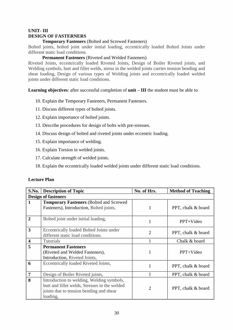
DESIGN OF FASTERNERS Temporary Fasteners (Bolted and Screwed Fasteners)
Bolted joints, bolted joint under initial loading, eccentrically loaded Bolted Joints under
different static load conditions.
Permanent Fasteners (Riveted and Welded Fasteners)
Riveted Joints, eccentrically loaded Riveted Joints, Design of Boiler Riveted joints, and
Welding symbols, butt and fillet welds, stress in the welded joints carries tension bending and
shear loading, Design of various types of Welding joints and eccentrically loaded welded
joints under different static load conditions.
Learning objectives: after successful completion of unit – III the student must be able to
1. Explain the Temporary Fasteners, Permanent Fasteners.
2. Discuss different types of bolted joints.
3. Explain importance of bolted joints.
4. Describe procedures for design of bolts with pre-stresses.
5. Discuss design of bolted and riveted joints under eccentric loading.
6. Explain importance of welding.
7. Explain Torsion in welded joints.
8. Calculate strength of welded joints.
9. Explain the eccentrically loaded welded joints under different static load conditions.
Lecture Plan
S.No. Description of Topic No. of Hrs. Method of Teaching
Design of fasteners
1 Temporary Fasteners (Bolted and Screwed
Fasteners), Introduction, Bolted joints,
1 PPT, chalk & board
2 Bolted joint under initial loading,
1 PPT+Video
3 Eccentrically loaded Bolted Joints under
different static load conditions. 2 PPT, chalk & board
4 Tutorials 1 Chalk & board
5 Permanent Fasteners (Riveted and Welded Fasteners),
Introduction, Riveted Joints,
1 PPT+Video
6 Eccentrically loaded Riveted Joints,
1 PPT, chalk & board
7 Design of Boiler Riveted joints, 1 PPT, chalk & board
8 Introduction to welding, Welding symbols,
butt and fillet welds, Stresses in the welded
joints due to tension bending and shear
loading,
2 PPT, chalk & board

18
9 Design of various types of Welding joints
1 PPT+Video
10 Eccentrically loaded welded joints, Welded
joints under different static load conditions. 1 PPT, chalk & board
11 Tutorials 2 Chalk & board
Assignment 3:
(1)A double riveted butt joint, in which the pitch of the rivets in the outer rows is twice that in
the inner rows, connects two 16 mm thick plates with two cover plates each 12 mm thick.
The diameter of the rivets is 22 mm. Determine the pitches of the rivets in the two rows if the
working stresses are not to exceed the following limits:
Tensile stress in plates = 100 MPa, Shear stress in rivets = 75 MPa and bearing
stresses in rivets and plates = 150 MPa.
Make a fully dimensioned sketch of the joint showing atleast two views.
[Question from Set No. 1, Nov. 2005/Regular
Examiniations]
(2)Two lengths of mild steel tie rod having width 200 mm are to be connected by means of
Lozenge joint with two cover plates to withstand a tensile load of 180 KN. Completely design
the joint, if the permissible stresses are 80 MPa in tension, 65 MPa in shear and 160 MPa in
crushing. Draw a neat sketch of the joint.
[Question fromSet No. 2, Nov. 2005/Regular
Examiniations]
(3)A triple riveted lap joint with zig-zag riveting is to be designed to connect two plates of 6
mm thickness. Determine the diameter of the rivet, pitch of rivets and distance between the
rows of the rivets. Indicate how the joint will fail. Also, find the efficiency of the joint. The
permissible stresses are 120 MPa in tension, 100 MPa in shear and 150 MPa in crushing.
[Question fromSet No. 3, Nov. 2005/Regular
Examiniations]
(4)A double riveted double cover butt joint in plates 20-mm thick is made with 25 mm
diameter rivets at 100 mm pitch. The permissible stresses are 120 MPa in tension, 100 MPa
in shear and 150 MPa in crushing. Find the efficiency of joint, taking the strength of the rivet
in double shear as twice than that of single shear.
[Question from Set No. 4, Nov. 2005/Regular
Examiniations]
(5) A double riveted lap joint is made between 15 mm thick plates. The rivet diameter and
pitch are 25 mm and 75 mm respectively. If the ultimate stresses are 400 MPa in tension, 320
MPa in shear and 640 MPa in crushing, find the minimum force per pitch which will rupture
the joint.If the above joint is subjected to a load such that the factor of safety is two, find out
the actual stresses developed in the plates and the rivets.
[Question from Set No. 1, May 2005/Supplementary
Examiniations]

19
(6)Two plates 16 mm thick are joined by a double riveted lap joint. The pitch of each row of
rivets is 90 mm. The rivets are 25 mm in diameter. The permissible stresses are 140 MPa in
tension, 80 MPa in shear and 160 MPa in crushing. Find the efficiency of the joint.
[Question from Set No. 2, May 2005/Supplementary
Examiniations]
UNIT-IV
DESIGN OF FLEXIBLE MECHANICAL ELEMENTS
Belt Drives:
Introduction, classification of belts, belt materials, design of flat (rectangular) belts,
ratio of belt tensions, V-Belts, power transmitted through V-Belt, design of V-Belts.
Springs:
Classification of springs, spring material, Design of helical, leaf, disc and tensional
springs under constant loads and varying loads.
Learning objectives: after successful completion of unit –IV the student must be able to
1. Classify the different types of blets and belt materials
2. Discuss ratio of belt tensions
3. Explain the power transmitted by flat and V-belts
4. Discuss the classification of springs and special features of each.
5. Derive the relations between stress and load & deflection and load for any type of
spring.
6. Describe the design procedure when springs under fatigue loading.
7. Design the helical springs.
Lecture Plan
S.No. Description of Topic No. of
Hrs.
Method of
Teaching
Design of flexible mechanical elements
1 Belt Drives: Introduction, classification of belts,
belt materials, 2 PPT+Video
2 Design of flat belts, ratio of belt tensions, 2
PPT, chalk &
board
3 V-Belts, power transmitted through V-Belt,
Design of V-Belts. 3
PPT, chalk &
board

20
4 Springs: Classification of springs, spring material, 2 PPT+Video
5 Design of helical, leaf, disc and tensional springs
under constant load. 1
PPT, chalk &
board
6 Design of helical, leaf, disc and tensional springs
under varying loads.
2 PPT, chalk &
board
7 Tutorials 2 Chalk & board
Assignment 4:
1. Discuss the classification of springs and special features of each.
2. Derive the relations between stress and load & deflection and load for any type of
spring.
3. Describe the design procedure when springs under fatigue loading.
4. Explain the concept of natural frequency of helical springs.
5. Derive the relations for energy storage capacity for various types of springs.
6. Differentiate the advantages of co-axial springs over other springs.
7. What are the different types of Belt used?
8. State the factors to be considered while selecting belt drive?
9. What is the difference between open and cross belt drive?
10. What are the different materials used for belt drive?
11. Which material is used for flat belt and v belt and rope drive?
12. State advantages & Disadvantages of V-belt over flat belt.
13. What is effect of following action taken are on belt adjusting mechanism.
14. Overtightening of pulley 2] under-tightening of pulley
15. Different between Flat belt and V – belt.
16. Define Angle of lap
17. What is slip in belts ? Write formula for % slip & state effect of slip on power
transmitted.
18. What do you mean by creep in belts ? What is its effect.?
19. What is crowning of pulley ? Why it is done.
20. What is centrifugal tension in belts ? What is its effect on power transmitted ? Write
condition for max power transmitted.
21. What do you mean by initial tension of the belt.
22. Derive expression for ratio of tension on tight side and slack side.
23. Two Parallel shafts are provided with pulleys 480mm and 640 mm diameters and
central distance is 3m. Find the length of 1) Crossed belt 2) Open belt.{Lc=7.843
meters, Lo=7.761 meters}

21
24. Two pulleys having diameters 800mm and 600mm are 8m apart, are connected by
crossed belt drive. Calculate the change in the length if direction of rotation of the
driven pulley to be reversed. {
25. Two Shafts with centre to centre distance between them as 3.5 meters, are having two pulleys with radii equal to 640 mm and 370 mm respectively. Find the length of crossed belt. {Lc=10.46 m B) Problems on slip in belts
26. Find the diameter of driven pulley rotating at 500 rpm if the driver pulley is 250mm in diameter and rotates at 100 rpm by using flat belt drive with 5% slip and the belt thickness is 5 mm. {48.68 mm}
27. A shaft runs at 80 rpm and drives another shaft at 150 rpm through belt drive. the diameter of driving pulley is 600mm . Determine the diameter of the driven pulley taking belt thickness 5mm and slip 4%. {0.3023 m or 302.3mm}
28. The speed of driving pulley is 600 rpm and that of driven pulley is 1800 rpm. If diameter of driving is 500 mm and that of driven is 155 mm. find % slip in belt if belt is 4 mm thick.s= 3.45 %}
29. A spring for a spring balance is required to have deflection of 60mm for a load of
1500 N. Design the spring assuming spring index 6. Take shear stress as 360 Mpa and
modulus of rigidity as 84 GPa. find free length of spring.
30. Design a spring to take a load of 300 N with spring index 8 and shear stress 400
MPa...The spring should deflect by 15 mm under this load..Take G= 84 GPa.
31. Model QP 3] Design a helical compression spring for a maximum load of 1000 N for
a deflection of 25mm using the value of spring index as 5 and Wahl’s correction
factor as 1.3. The maximum permissible shear stress for the spring wire is 400 Mpa
and modulus of rigidity 84 KN/mm2.
32. W-2013-8 marks 4] The spring of spring balance, elongates by 150 mm, when
subjected to a load of 400 N. the spring index is 6. Take permissible shear stress for
the wire material 540 MPa and G=84 Gpa..Determine
1) the wire diameter 2) the diameter of Coil 3) No of turns. {W-2010}
33. A helical spring is made from a wire of diameter 6mm diameter and has outside
diameter of 75 mm. If the permissible shear stress is 350 MPa and modulus of rigidity
is 84 kN/mm2. find the axial load which the spring can carry and the deflection per
active turn.
Take Wahl’s correction factor .
{W=383.4 N, {S-2009}
34. A closed coil helical spring is used for an automobile suspension system. The spring
has stiffness 85 N/mm with square and ground ends. The load on the spring causes a

22
total deflection of 9 mm. Taking permissible shear stress 400 MPa spring index 6 and
G=80 GPa.Find,
1) Wire diameter of spring, 2) Length of spring.
35. Design a helical compression spring for a maximum load of 1000 N for a deflection
of 23mm using spring index 5. The maximum permissible shear stress is 420 MPa and
modulus of rigidity is 84 GPa.Find the pitch of spring assuming square and ground
ends.
{d=6.3 mm ,D=35 mm,n=13.44 turns, Lf=138.45, p=9.23 mm}S-2012 8
marks Important
36. Design a close coiled helical compression spring for a service load ranging from 2250
to 2750. The axial deflection of the spring for the load range is 6mm. Assume a spring
index of 5. , Neglect the effect of stress
concentration . Draw fully dimensioned sketch of the spring showing the details of the
finish of the end coils. Assume squared and ground ends.
{ pitch
=13.80mm}
37. Design a helical spring with square and ground ends for a load ranging from 80 N to
145 N when required deflection is 6.5 mm. Take spring index as 8 ,permissible shear
stress for the wire material 475 MPa and G=84 Gpa.
{ pitch
=6.19mm}
38. Design and draw a valve spring of a petrol engine for the following operating
conditions :
Spring load when the valve is open = 400 N
Spring load when the valve is closed = 250 N
Maximum inside diameter of spring = 25 mm
Length of the spring when the valve is open = 40 mm
Length of the spring when the valve is closed = 50 mm
Maximum permissible shear stress = 400 MPa
UNIT-V
DESIGN OF SHAFTS AND KEYS
Transmission shafts, Design of solid and hollow shafts based on strength, rigidity and
Flexible shafts, shaft and axles – key and classification of keys, stresses in the keys, design
considerations, effect of key way on the shaft strength.
Learning objectives: after successful completion of unit –V the student must be able to
1 Explain the Transmission shafts
2 Design of solid and hollow shafts based on strength and rigidity
3 Discuss about different types of keys and their function

23
4 Explain the different types of stresses developed in keys
5 Enumerate the design considerations of keys
6 Explain the effect of key way on the shaft strength.
Lecture Plan
S.No. Description of Topic No. of Hrs. Method of Teaching
Design of shafts and Keys.
1 Introduction to Transmission shafts, 1 PPT+Video
2 Design of solid and hollow shafts based on
strength and rigidity 2 PPT, chalk & board
3 Flexible shafts, shaft and axles. 1 PPT, chalk & board
4 Introduction to key and classification of keys, 1 PPT+Video
5 Stresses in the keys, Design considerations, 2 PPT, chalk & board
6 Effect of key way on the shaft strength 1 PPT, chalk & board
7 Tutorials 2 PPT, chalk & board
Assignment 5:
1. Explain the effect of key way on the strength of a shaft.
2. Write the comparison between solid shafts, hollow shafts and spindles.
3. A shaft is required to transfer 43KW of power at 600 rpm. The outside diameter must not
exceed 50 mm and the maximum shear stress is not to exceed 70 N/mm2. Find out the
dimensions of hollow and solid shaft, which would meet their requirements. Also compare
their weights.
4. Compute the diameter of a solid shaft which has to transmit 16KW power at 300 rpm.
Ultimate shear stress per shaft material is 350 N/mm2 and factor of safety for design is 6. If
a hollow shaft replaces the solid shaft, find the inside and outside diameters if the ratio is
0.5.
5. A shaft is supported by two bearings placed 1.2 m apart. A 600 mm diameter pulley is
mounted at a distance of 300mm to the right of left hand bearing and this drives a pulley
directly below it with the help of a belt having maximum tension of 2kN. Another pulley
400 mm diameter is placed 200 mm to the left hand bearing and is driven with the help of
an electric motor and belt which is placed horizontally to the right. The angle of contact for
both the pulleys is 1800
and coefficient of friction is 0.24. Calculate the diameter of the shaft
taking working stresses of 63 Mpa in tension and 42 Mpa in shear.
6. A shaft running at 400 rpm transmits 10 kW. Assuming allowable shear stress in shaft is 40
Mpa, find the diameter of the shaft.
7. Determine the diameter of the hollow shaft with inside dia = 0.6 outside dia. The shaft is
driven by an overhung pulley of 90 cm diameter. Take weight of pulley is 60 kg, the belt
tensions as 290 and 100 kg, over hang= 25 cm, angle of lap is 1800.

24
VNR VIGNANA JYOTHI INSTITUTE OF ENGINEERING & TECHNOLOGY
(Autonomous)
DEPARTMENT OF MECHANICAL ENGINEERING
II B. Tech, Ist Semester (Mechanical Engineering)
Subject : Mechanical Engineering Design - I
Subject Code : 13MED 011
Academic Year : 2016 – 17
Number of working days : 90
Number of Hours / week : 4 + 1
Total number of periods planned : 80
Name of the Faculty Member : Dr. G. S. Gupta / V. Anandkumar
Course Objectives:
Understand different properties of Materials and relationship between them.
Understand the principles of stress, strain and Principal stresses as applied to Solid bodies or structural and machine elements under loads.
Understand to form mathematical equation and analyze problems by making appropriate a s s u m p t i o n s and learn systematic engineering method to solve practical Design engineering problems.
Course Outcomes (COs): Upon completion of this course, students should be able to:
CO-1 : Model and analyze design problems in Mechanical and structural engineering.
CO-2 : Apply knowledge of standard elements and their technical information available in
the data bases and in designing machine elements.
CO-3 : Predict modes of failure in materials or machine elements caused by different types
of loads under operation.
UNIT-I
ENGINEERING MATERIALS AND DESIGN CONSIDERATIONS The Design Phase / Methodology, and identification of need, Evaluation and Presentation,
Reliability and Product liability. Mechanical Properties of Engineering Materials, overall
design considerations, Factor safety, Preferred Numbers. Standard and codes, design data
handbook. Load, stress and critical sections in machine parts. Static strength, plastic
deformation, temperature properties, Definition of stress, simple stress, combined stress,
complex stress. Members subjected to axial, bending, torsion and shear loading, impact
stresses.
Learning objectives: after successful completion of unit – I the student must be able to
8. Discuss the important phases of design
9. Explain the importance of standardization
10. Define factor of safety and explain its importance.
25
11. Enumerate manufacturing considerations in design.
12. Discuss the terms codes and standards, Reliability.
13. Enumerate various types of stresses and develop the relation between them
14. Discuss the concept of stiffness in tension, bending, torsion and combined loading
situations.
Lecture Plan
S.No. Description of Topic No. of Hrs. Method of Teaching
Engineering Materials and Design Considerations
1 Introduction, The Design Phase /
Methodology. 1 PPT+Video
2 Identification of need, Evaluation and
Presentation, Reliability and Product liability. 2 PPT+Video
3 Mechanical Properties of Engineering
Materials. 1 PPT
4 Overall design considerations, Factor safety, 1 PPT
5 Preferred Numbers. Standard and codes,
design data handbook. 2 PPT, chalk & board
6 Load, stress and critical sections in machine
parts. 1 Chalk & board
7 Static strength, plastic deformation,
temperature properties, 1 PPT, chalk & board
8
Definition of stress, simple stress, combined
stress, complex stress. Members subjected to
axial, bending, torsion and shear loading,
impact stresses.
2 PPT, chalk & board
9 Tutorial 2 Chalk & board
Assignment 1:
4. Discuss general considerations in the design of Engineering material
5. State and explain various properties of Engineering materials
6. Explain various factors which govern the selection of engineering materials
15. Enumerate manufacturing considerations in design.
16. Explain the terms Tolerances and fits and its importance in manufacturing of
materials.
17. Discuss BIS codes of steels
18. Enumerate various types of stresses and develop the relation between stress and
strain.
19. State and explain various theories of failures and their application in design of
engineering materials.
20. Define factor of safety and explain its importance.
21. Discuss the term Design for strength and rigidity.
22. Explain the term preferred numbers.
23. Discuss the concept of stiffness in tension, bending, torsion and combined loading
situations.

26
24. Explain concept static strength design based on fracture toughness.
25. A machine member 0.05m diameter and 0.25 m long is supported at one end as a
cantilever. The transverse load at the free end is 2750 N causes bending, axial load is
13.75 KN and twisting moment at the free end is 250Nm. Determine principle stresses
and maximum shear stresses for the following cases.
(a)Bending and torsion loads
(b)Bending and axial loads
(c)Torsion and axial loads\
(d)Bending, axial and torsional loads
21. A bolt is subjected to an axial force of 10 KN with a transverse shear force of 5 KN.
The permissible tensile stress at elastic limit is 100 MPa and the poissions ratio is 0.3
for the bolt material. Determine the diameter of the bolt required according to each
theory of failure.
22. A shaft is designed based on maximum distortion energy theory with a factor of safety
of 2.0. The material used is 30C8 steel with a yield stress of 310 MPa. It is subjected
to an axial load of 40 KN. Determine the maximum torque capacity. Diameter of shaft
is 20 mm.
23. A 50 mm diameter steel shaft is supported on bearings 1.5m apart and carries a fly
wheel weighing ‘W’. The allowable bending stress for the shaft material and the
maximum deflection are limited to 100 MPa and 2 mm respectively. The young’s
modulus for the shaft material is 210 GPa. Determine the Maximum permissible
weight of the flywheel.
24. The diameter of a piston of the steam engine is 250 mm and the maximum steam
pressure is 0.8 N/mm2
, find the size of the piston rod.
25. A flange coupling is held together by four M24 bolts, and arranged on bolt circle of
150 mm. Each bolt is initially tightened to a load of 50 KN to make a tight joint. The
power transmitted by the coupling is 5Kw at a speed of 600 RPM. Estimate the
Maximum Normal and Shear Stresses in the Bolt Material.
26. A hollow shaft is required to transmit 600 KW at 110 rpm the maximum torque being
20% greater than the mean. The shear stress is not to exceed 63 MPa and twist in a
length of 3 meters not to exceed 1.4 degrees. Find the external diameter of the shaft, if
the internal diameter to the external diameter is 3/8. Take G = 84 GPa.
UNIT – II
DESIGN AGAINST FLUCTUATING LOAD
Stress concentration, stress concentration factors, Reduction stress concentration,
fluctuating stresses. Fatigue strength, Endurance Limit, fatigue test, S-N diagrams for
different structural materials. Low cycle and high cycle fatigue, Notch sensitivity, Design for

27
finite and infinite life. Soderberg and Goodman lines the fatigue strength, modified Goodman
theory.
Learning objectives: after successful completion of unit – II the student must be able to
6. Explain the terms stress concentration, theoretical stress concentration factor, fatigue
stress concentration factor, notch sensitivity and develop the relation between them.
7. Explain the S-N diagrams for different structural materials
8. Discuss the finite and infinite life.
9. Explain the Soderberg and Goodman lines the fatigue strength
10. Discuss the concept involved in Goodman’s line, Soderberg’s line and Modified
Goodman’s line.
Lecture Plan
S.No. Description of Topic No. of Hrs. Method of Teaching
Design against Fluctuating Load
1 Stress concentration, stress concentration
factors, 1 PPT+Video
2 Reduction stress concentration, Fluctuating
stresses. 1 PPT, chalk & board
3 Fatigue strength, Endurance Limit, 1 PPT, chalk & board
4 Fatigue test, S-N diagrams for different
structural materials. 1 PPT+Video
5 Low cycle and high cycle fatigue, Notch
sensitivity, 1 PPT, chalk & board
6 Design for finite and infinite life. 1 PPT, chalk & board
7 Soderberg and Goodman lines the fatigue
strength, 1 PPT
modified Goodman theory, 1 PPT
Tutorial 2 Chalk & board
Assignment 2:
1. A 40 mm diameter shaft is made of steel 50C4 (Sut = 660 N/mm
2
) and has a machined
surface. The expected reliability is 99%. The theoretical stress concentration factor for the
shape of the shaft is 1.6 and the notch sensitivity factor is 0.9. Determine the endurance
strength of the shaft.
2.A shaft supported as a simple beam, 0.45 mm long, is made of AISI 3120 steel. With the
shaft rotating a steady load of 8000 N is applied midway between the bearings. The surfaces
are ground. Indefinite life is desired with a factor of safety of 1.6 based on endurance
strength. What should be the minimum diameter of the shaft if there are no surface
discontinuities? Endurance limit is 630 MPa. Size factor is 0.85 and machine surface finish
factor 0.87.
2 2
28
(6) A bar of circular cross-section is subjected to alternating tensile forces varying from
a minimum of 200 kN to a maximum of 500kN. It is to be manufactured of a material
with an ultimate tensile strength of 900 MPa and an endurance limit of 700 MPa.
Determine the diameter of bar using safety factors of 3.5 related to ultimate tensile
strength and 4 related to endurance limit and a stress concentration factor of 1.65 for
fatigue load. Use Goodman straight line as basis for design.
(7) A steel connecting rod is subjected to a completely reversed axial load of 120 KN.
Suggest the suitable size of the rod using a factor of safety 1.8. The ultimate strength of
the material is 1000 MPa.
Load correction factor 0.7
Size factor0.85
Surface finish factor 0.8
(8) A pulley is keyed to a shaft midway between two anti-friction bearings. The bending
moment of the pulley varies from 150 Nm to 450 Nm as torsional moment of the shaft
varies from 50 Nm to 150 Nm. The frequency of variation of the loads is the same as
the shaft speed. The shaft is made of cold drawn steel having an ultimate strength of
550 MPa and yield strength of 310 MPa. Determine the required diameter for an
indefinite life. The stress concentration factor for the key way in bending and torsion
may be taken as 1.6 and 1.3 respectively. Use a design factor of 1.8, size factor 0.85 and
surface correction factor 0.88.
Use for torsion,
Size correction factor = 0.6 and
The nominal design torsion stress = 0.6 Yield point in tension.
(3) A leaf spring in an automobile is subjected to cyclical stresses.
The average stress = 150 MPa, variable stress = 50 MPa, Ultimate stress = 630 MPa, Yield
point stress = 350 MPa and endurance limit = 150 MPa. Estimate under what factor of safety
the spring is working, by Goodman and Soderberg formulae.
(4) A stepped shaft transmits a torque varying from 800 Nm to 1200 Nm. The ratio of
diameter is 1.5and the stress concentration factor is 1.2. Determine the diameter of the shaft
for an infinite life for a design factor of safety 1.8. The Ultimate tensile strength of the
material of the shaft is 600 MPa. Yield stress of the material is 450 MPa. Consider the size
effect and surgace finish effect.
(5)A round shaft made of cold finished AISI 1020 steel is subjected to a variable torque
whose maximum value is 700 KN-m. For a factor of safety of 1.5 on the Soderberg criterion,
determine the diameter of the shaft if
a.The torque is reversed
b.The torque varies from zero to maximum
c.The torque varies from 300 Nm to a maximum

29
(9) A shaft is made of steel ultimate tensile strength 700 MPa and yield point 420 MPa
is subjected to a torque varying from 200N m anti-clockwise to 600 Nm clockwise.
Calculate the diameter of the shaft if the factor of safetyis 2 and it is based on the yield
point and the endurance strength in shear.
(10) A hot rolled shaft is subjected to torsional load that varies from 320 Nm clockwise
to 120 Nm anti-clockwise and an applied bending moment at a critical section varies
from 400 Nm to 200 Nm. The shaft is of uniform cross section. Determine the required
shaft diameter. The material has an ultimate strength of 560 MPa and yield strength of
420 MPa. Assume factor of safety to be 2.
(11) Bending stress in a machine part fluctuate between a tensile stress of 280 MPa and
compressive stress of 140 MPa. What should be the minimum ultimate tensile strength
to carry this fluctuation indefinitely according to
(i)Goodman’s formula
(ii)Soderberg’s formula
The factor of safety may be assumed to be 1.75. Assume that yield point is never likely
to be less than 55% of the ultimate tensile strength or greater than 93 % of it.
30
UNIT- III
DESIGN OF FASTERNERS Temporary Fasteners (Bolted and Screwed Fasteners)
Bolted joints, bolted joint under initial loading, eccentrically loaded Bolted Joints under
different static load conditions.
Permanent Fasteners (Riveted and Welded Fasteners)
Riveted Joints, eccentrically loaded Riveted Joints, Design of Boiler Riveted joints, and
Welding symbols, butt and fillet welds, stress in the welded joints carries tension bending and
shear loading, Design of various types of Welding joints and eccentrically loaded welded
joints under different static load conditions.
Learning objectives: after successful completion of unit – III the student must be able to
10. Explain the Temporary Fasteners, Permanent Fasteners.
11. Discuss different types of bolted joints.
12. Explain importance of bolted joints.
13. Describe procedures for design of bolts with pre-stresses.
14. Discuss design of bolted and riveted joints under eccentric loading.
15. Explain importance of welding.
16. Explain Torsion in welded joints.
17. Calculate strength of welded joints.
18. Explain the eccentrically loaded welded joints under different static load conditions.
Lecture Plan
S.No. Description of Topic No. of Hrs. Method of Teaching
Design of fasteners
1 Temporary Fasteners (Bolted and Screwed
Fasteners), Introduction, Bolted joints,
1 PPT, chalk & board
2 Bolted joint under initial loading,
1 PPT+Video
3 Eccentrically loaded Bolted Joints under
different static load conditions. 2 PPT, chalk & board
4 Tutorials 1 Chalk & board
5 Permanent Fasteners (Riveted and Welded Fasteners),
Introduction, Riveted Joints,
1 PPT+Video
6 Eccentrically loaded Riveted Joints,
1 PPT, chalk & board
7 Design of Boiler Riveted joints, 1 PPT, chalk & board
8 Introduction to welding, Welding symbols,
butt and fillet welds, Stresses in the welded
joints due to tension bending and shear
loading,
2 PPT, chalk & board

31
9 Design of various types of Welding joints
1 PPT+Video
10 Eccentrically loaded welded joints, Welded
joints under different static load conditions. 1 PPT, chalk & board
11 Tutorials 2 Chalk & board
Assignment 3:
(1)A double riveted butt joint, in which the pitch of the rivets in the outer rows is twice that in
the inner rows, connects two 16 mm thick plates with two cover plates each 12 mm thick.
The diameter of the rivets is 22 mm. Determine the pitches of the rivets in the two rows if the
working stresses are not to exceed the following limits:
Tensile stress in plates = 100 MPa, Shear stress in rivets = 75 MPa and bearing
stresses in rivets and plates = 150 MPa.
Make a fully dimensioned sketch of the joint showing atleast two views.
[Question from Set No. 1, Nov. 2005/Regular
Examiniations]
(2)Two lengths of mild steel tie rod having width 200 mm are to be connected by means of
Lozenge joint with two cover plates to withstand a tensile load of 180 KN. Completely design
the joint, if the permissible stresses are 80 MPa in tension, 65 MPa in shear and 160 MPa in
crushing. Draw a neat sketch of the joint.
[Question fromSet No. 2, Nov. 2005/Regular
Examiniations]
(3)A triple riveted lap joint with zig-zag riveting is to be designed to connect two plates of 6
mm thickness. Determine the diameter of the rivet, pitch of rivets and distance between the
rows of the rivets. Indicate how the joint will fail. Also, find the efficiency of the joint. The
permissible stresses are 120 MPa in tension, 100 MPa in shear and 150 MPa in crushing.
[Question fromSet No. 3, Nov. 2005/Regular
Examiniations]
(4)A double riveted double cover butt joint in plates 20-mm thick is made with 25 mm
diameter rivets at 100 mm pitch. The permissible stresses are 120 MPa in tension, 100 MPa
in shear and 150 MPa in crushing. Find the efficiency of joint, taking the strength of the rivet
in double shear as twice than that of single shear.
[Question from Set No. 4, Nov. 2005/Regular
Examiniations]
(5) A double riveted lap joint is made between 15 mm thick plates. The rivet diameter and
pitch are 25 mm and 75 mm respectively. If the ultimate stresses are 400 MPa in tension, 320
MPa in shear and 640 MPa in crushing, find the minimum force per pitch which will rupture
the joint.If the above joint is subjected to a load such that the factor of safety is two, find out
the actual stresses developed in the plates and the rivets.
[Question from Set No. 1, May 2005/Supplementary
Examiniations]

32
(6)Two plates 16 mm thick are joined by a double riveted lap joint. The pitch of each row of
rivets is 90 mm. The rivets are 25 mm in diameter. The permissible stresses are 140 MPa in
tension, 80 MPa in shear and 160 MPa in crushing. Find the efficiency of the joint.
[Question from Set No. 2, May 2005/Supplementary
Examiniations]
UNIT-IV
DESIGN OF FLEXIBLE MECHANICAL ELEMENTS
Belt Drives:
Introduction, classification of belts, belt materials, design of flat (rectangular) belts,
ratio of belt tensions, V-Belts, power transmitted through V-Belt, design of V-Belts.
Springs:
Classification of springs, spring material, Design of helical, leaf, disc and tensional
springs under constant loads and varying loads.
Learning objectives: after successful completion of unit –IV the student must be able to
8. Classify the different types of blets and belt materials
9. Discuss ratio of belt tensions
10. Explain the power transmitted by flat and V-belts
11. Discuss the classification of springs and special features of each.
12. Derive the relations between stress and load & deflection and load for any
type of spring.
13. Describe the design procedure when springs under fatigue loading.
14. Design the helical springs.
Lecture Plan
S.No. Description of Topic No. of
Hrs.
Method of
Teaching
Design of flexible mechanical elements
1 Belt Drives: Introduction, classification of belts,
belt materials, 2 PPT+Video
2 Design of flat belts, ratio of belt tensions, 2
PPT, chalk &
board
3 V-Belts, power transmitted through V-Belt,
Design of V-Belts. 3
PPT, chalk &
board

33
4 Springs: Classification of springs, spring material, 2 PPT+Video
5 Design of helical, leaf, disc and tensional springs
under constant load. 1
PPT, chalk &
board
6 Design of helical, leaf, disc and tensional springs
under varying loads.
2 PPT, chalk &
board
7 Tutorials 2 Chalk & board
Assignment 4:
39. Discuss the classification of springs and special features of each.
40. Derive the relations between stress and load & deflection and load for any type of
spring.
41. Describe the design procedure when springs under fatigue loading.
42. Explain the concept of natural frequency of helical springs.
43. Derive the relations for energy storage capacity for various types of springs.
44. Differentiate the advantages of co-axial springs over other springs.
45. What are the different types of Belt used?
46. State the factors to be considered while selecting belt drive?
47. What is the difference between open and cross belt drive?
48. What are the different materials used for belt drive?
49. Which material is used for flat belt and v belt and rope drive?
50. State advantages & Disadvantages of V-belt over flat belt.
51. What is effect of following action taken are on belt adjusting mechanism.
52. Overtightening of pulley 2] under-tightening of pulley
53. Different between Flat belt and V – belt.
54. Define Angle of lap
55. What is slip in belts ? Write formula for % slip & state effect of slip on power
transmitted.
56. What do you mean by creep in belts ? What is its effect.?
57. What is crowning of pulley ? Why it is done.
58. What is centrifugal tension in belts ? What is its effect on power transmitted ? Write
condition for max power transmitted.
59. What do you mean by initial tension of the belt.
60. Derive expression for ratio of tension on tight side and slack side.
61. Two Parallel shafts are provided with pulleys 480mm and 640 mm diameters and
central distance is 3m. Find the length of 1) Crossed belt 2) Open belt.{Lc=7.843
meters, Lo=7.761 meters}
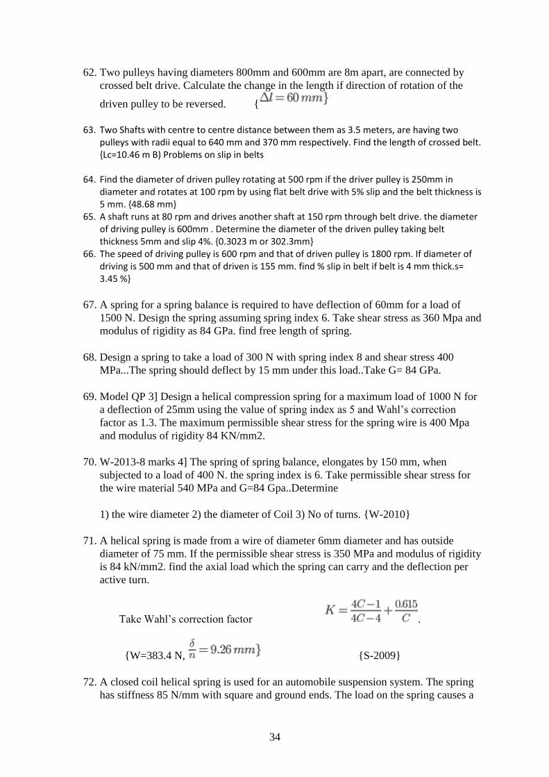
34
62. Two pulleys having diameters 800mm and 600mm are 8m apart, are connected by
crossed belt drive. Calculate the change in the length if direction of rotation of the
driven pulley to be reversed. {
63. Two Shafts with centre to centre distance between them as 3.5 meters, are having two pulleys with radii equal to 640 mm and 370 mm respectively. Find the length of crossed belt. {Lc=10.46 m B) Problems on slip in belts
64. Find the diameter of driven pulley rotating at 500 rpm if the driver pulley is 250mm in diameter and rotates at 100 rpm by using flat belt drive with 5% slip and the belt thickness is 5 mm. {48.68 mm}
65. A shaft runs at 80 rpm and drives another shaft at 150 rpm through belt drive. the diameter of driving pulley is 600mm . Determine the diameter of the driven pulley taking belt thickness 5mm and slip 4%. {0.3023 m or 302.3mm}
66. The speed of driving pulley is 600 rpm and that of driven pulley is 1800 rpm. If diameter of driving is 500 mm and that of driven is 155 mm. find % slip in belt if belt is 4 mm thick.s= 3.45 %}
67. A spring for a spring balance is required to have deflection of 60mm for a load of
1500 N. Design the spring assuming spring index 6. Take shear stress as 360 Mpa and
modulus of rigidity as 84 GPa. find free length of spring.
68. Design a spring to take a load of 300 N with spring index 8 and shear stress 400
MPa...The spring should deflect by 15 mm under this load..Take G= 84 GPa.
69. Model QP 3] Design a helical compression spring for a maximum load of 1000 N for
a deflection of 25mm using the value of spring index as 5 and Wahl’s correction
factor as 1.3. The maximum permissible shear stress for the spring wire is 400 Mpa
and modulus of rigidity 84 KN/mm2.
70. W-2013-8 marks 4] The spring of spring balance, elongates by 150 mm, when
subjected to a load of 400 N. the spring index is 6. Take permissible shear stress for
the wire material 540 MPa and G=84 Gpa..Determine
1) the wire diameter 2) the diameter of Coil 3) No of turns. {W-2010}
71. A helical spring is made from a wire of diameter 6mm diameter and has outside
diameter of 75 mm. If the permissible shear stress is 350 MPa and modulus of rigidity
is 84 kN/mm2. find the axial load which the spring can carry and the deflection per
active turn.
Take Wahl’s correction factor .
{W=383.4 N, {S-2009}
72. A closed coil helical spring is used for an automobile suspension system. The spring
has stiffness 85 N/mm with square and ground ends. The load on the spring causes a
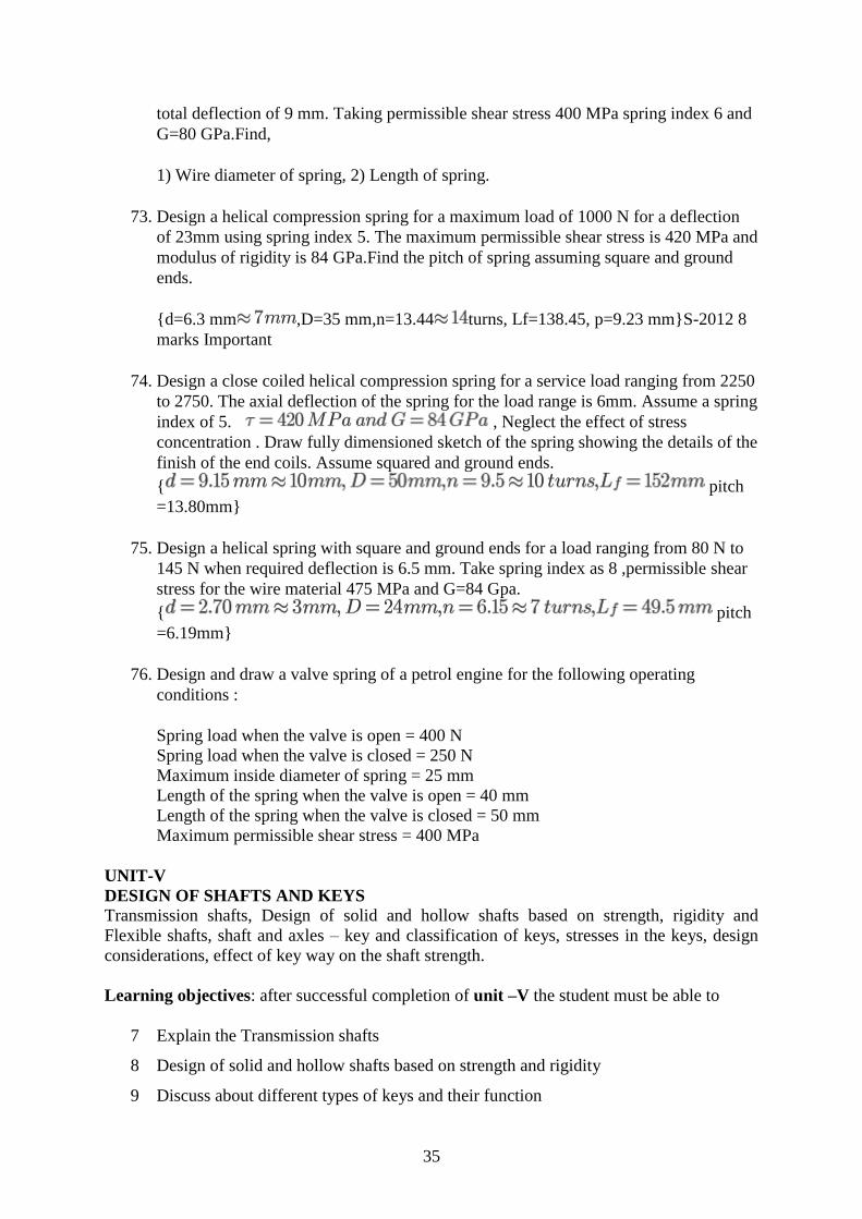
35
total deflection of 9 mm. Taking permissible shear stress 400 MPa spring index 6 and
G=80 GPa.Find,
1) Wire diameter of spring, 2) Length of spring.
73. Design a helical compression spring for a maximum load of 1000 N for a deflection
of 23mm using spring index 5. The maximum permissible shear stress is 420 MPa and
modulus of rigidity is 84 GPa.Find the pitch of spring assuming square and ground
ends.
{d=6.3 mm ,D=35 mm,n=13.44 turns, Lf=138.45, p=9.23 mm}S-2012 8
marks Important
74. Design a close coiled helical compression spring for a service load ranging from 2250
to 2750. The axial deflection of the spring for the load range is 6mm. Assume a spring
index of 5. , Neglect the effect of stress
concentration . Draw fully dimensioned sketch of the spring showing the details of the
finish of the end coils. Assume squared and ground ends.
{ pitch
=13.80mm}
75. Design a helical spring with square and ground ends for a load ranging from 80 N to
145 N when required deflection is 6.5 mm. Take spring index as 8 ,permissible shear
stress for the wire material 475 MPa and G=84 Gpa.
{ pitch
=6.19mm}
76. Design and draw a valve spring of a petrol engine for the following operating
conditions :
Spring load when the valve is open = 400 N
Spring load when the valve is closed = 250 N
Maximum inside diameter of spring = 25 mm
Length of the spring when the valve is open = 40 mm
Length of the spring when the valve is closed = 50 mm
Maximum permissible shear stress = 400 MPa
UNIT-V
DESIGN OF SHAFTS AND KEYS
Transmission shafts, Design of solid and hollow shafts based on strength, rigidity and
Flexible shafts, shaft and axles – key and classification of keys, stresses in the keys, design
considerations, effect of key way on the shaft strength.
Learning objectives: after successful completion of unit –V the student must be able to
7 Explain the Transmission shafts
8 Design of solid and hollow shafts based on strength and rigidity
9 Discuss about different types of keys and their function

36
10 Explain the different types of stresses developed in keys
11 Enumerate the design considerations of keys
12 Explain the effect of key way on the shaft strength.
Lecture Plan
S.No. Description of Topic No. of Hrs. Method of Teaching
Design of shafts and Keys.
1 Introduction to Transmission shafts, 1 PPT+Video
2 Design of solid and hollow shafts based on
strength and rigidity 2 PPT, chalk & board
3 Flexible shafts, shaft and axles. 1 PPT, chalk & board
4 Introduction to key and classification of keys, 1 PPT+Video
5 Stresses in the keys, Design considerations, 2 PPT, chalk & board
6 Effect of key way on the shaft strength 1 PPT, chalk & board
7 Tutorials 2 PPT, chalk & board
Assignment 5:
8. Explain the effect of key way on the strength of a shaft.
9. Write the comparison between solid shafts, hollow shafts and spindles.
10. A shaft is required to transfer 43KW of power at 600 rpm. The outside diameter must not
exceed 50 mm and the maximum shear stress is not to exceed 70 N/mm2. Find out the
dimensions of hollow and solid shaft, which would meet their requirements. Also compare
their weights.
11. Compute the diameter of a solid shaft which has to transmit 16KW power at 300 rpm.
Ultimate shear stress per shaft material is 350 N/mm2 and factor of safety for design is 6. If
a hollow shaft replaces the solid shaft, find the inside and outside diameters if the ratio is
0.5.
12. A shaft is supported by two bearings placed 1.2 m apart. A 600 mm diameter pulley is
mounted at a distance of 300mm to the right of left hand bearing and this drives a pulley
directly below it with the help of a belt having maximum tension of 2kN. Another pulley
400 mm diameter is placed 200 mm to the left hand bearing and is driven with the help of
an electric motor and belt which is placed horizontally to the right. The angle of contact for
both the pulleys is 1800
and coefficient of friction is 0.24. Calculate the diameter of the shaft
taking working stresses of 63 Mpa in tension and 42 Mpa in shear.
13. A shaft running at 400 rpm transmits 10 kW. Assuming allowable shear stress in shaft is 40
Mpa, find the diameter of the shaft.
14. Determine the diameter of the hollow shaft with inside dia = 0.6 outside dia. The shaft is
driven by an overhung pulley of 90 cm diameter. Take weight of pulley is 60 kg, the belt
tensions as 290 and 100 kg, over hang= 25 cm, angle of lap is 1800.

37
VNR VIGNANA JYOTHI INSTITUTE OF ENGINEERING & TECHNOLOGY
(Autonomous)
DEPARTMENT OF MECHANICAL ENGINEERING
II B. Tech, Ist Semester (Mechanical Engineering)
Subject : Mechanical Engineering Design - I
Subject Code : 13MED 011
Academic Year : 2016 – 17
Number of working days : 90
Number of Hours / week : 4 + 1
Total number of periods planned : 80
Name of the Faculty Member : Dr. G. S. Gupta / V. Anandkumar
Course Objectives:
Understand different properties of Materials and relationship between them.
Understand the principles of stress, strain and Principal stresses as applied to Solid bodies or structural and machine elements under loads.
Understand to form mathematical equation and analyze problems by making appropriate a s s u m p t i o n s and learn systematic engineering method to solve practical Design engineering problems.
Course Outcomes (COs): Upon completion of this course, students should be able to:
CO-1 : Model and analyze design problems in Mechanical and structural engineering.
CO-2 : Apply knowledge of standard elements and their technical information available in
the data bases and in designing machine elements.
CO-3 : Predict modes of failure in materials or machine elements caused by different types
of loads under operation.
UNIT-I
ENGINEERING MATERIALS AND DESIGN CONSIDERATIONS The Design Phase / Methodology, and identification of need, Evaluation and Presentation,
Reliability and Product liability. Mechanical Properties of Engineering Materials, overall
design considerations, Factor safety, Preferred Numbers. Standard and codes, design data
handbook. Load, stress and critical sections in machine parts. Static strength, plastic
deformation, temperature properties, Definition of stress, simple stress, combined stress,
complex stress. Members subjected to axial, bending, torsion and shear loading, impact
stresses.
Learning objectives: after successful completion of unit – I the student must be able to
15. Discuss the important phases of design
16. Explain the importance of standardization
17. Define factor of safety and explain its importance.

38
18. Enumerate manufacturing considerations in design.
19. Discuss the terms codes and standards, Reliability.
20. Enumerate various types of stresses and develop the relation between them
21. Discuss the concept of stiffness in tension, bending, torsion and combined loading
situations.
Lecture Plan
S.No. Description of Topic No. of Hrs. Method of Teaching
Engineering Materials and Design Considerations
1 Introduction, The Design Phase /
Methodology. 1 PPT+Video
2 Identification of need, Evaluation and
Presentation, Reliability and Product liability. 2 PPT+Video
3 Mechanical Properties of Engineering
Materials. 1 PPT
4 Overall design considerations, Factor safety, 1 PPT
5 Preferred Numbers. Standard and codes,
design data handbook. 2 PPT, chalk & board
6 Load, stress and critical sections in machine
parts. 1 Chalk & board
7 Static strength, plastic deformation,
temperature properties, 1 PPT, chalk & board
8
Definition of stress, simple stress, combined
stress, complex stress. Members subjected to
axial, bending, torsion and shear loading,
impact stresses.
2 PPT, chalk & board
9 Tutorial 2 Chalk & board
Assignment 1:
7. Discuss general considerations in the design of Engineering material
8. State and explain various properties of Engineering materials
9. Explain various factors which govern the selection of engineering materials
26. Enumerate manufacturing considerations in design.
27. Explain the terms Tolerances and fits and its importance in manufacturing of
materials.
28. Discuss BIS codes of steels
29. Enumerate various types of stresses and develop the relation between stress and
strain.
30. State and explain various theories of failures and their application in design of
engineering materials.
31. Define factor of safety and explain its importance.
32. Discuss the term Design for strength and rigidity.
33. Explain the term preferred numbers.
34. Discuss the concept of stiffness in tension, bending, torsion and combined loading
situations.

39
35. Explain concept static strength design based on fracture toughness.
36. A machine member 0.05m diameter and 0.25 m long is supported at one end as a
cantilever. The transverse load at the free end is 2750 N causes bending, axial load is
13.75 KN and twisting moment at the free end is 250Nm. Determine principle stresses
and maximum shear stresses for the following cases.
(a)Bending and torsion loads
(b)Bending and axial loads
(c)Torsion and axial loads\
(d)Bending, axial and torsional loads
27. A bolt is subjected to an axial force of 10 KN with a transverse shear force of 5 KN.
The permissible tensile stress at elastic limit is 100 MPa and the poissions ratio is 0.3
for the bolt material. Determine the diameter of the bolt required according to each
theory of failure.
28. A shaft is designed based on maximum distortion energy theory with a factor of safety
of 2.0. The material used is 30C8 steel with a yield stress of 310 MPa. It is subjected
to an axial load of 40 KN. Determine the maximum torque capacity. Diameter of shaft
is 20 mm.
29. A 50 mm diameter steel shaft is supported on bearings 1.5m apart and carries a fly
wheel weighing ‘W’. The allowable bending stress for the shaft material and the
maximum deflection are limited to 100 MPa and 2 mm respectively. The young’s
modulus for the shaft material is 210 GPa. Determine the Maximum permissible
weight of the flywheel.
30. The diameter of a piston of the steam engine is 250 mm and the maximum steam
pressure is 0.8 N/mm2
, find the size of the piston rod.
31. A flange coupling is held together by four M24 bolts, and arranged on bolt circle of
150 mm. Each bolt is initially tightened to a load of 50 KN to make a tight joint. The
power transmitted by the coupling is 5Kw at a speed of 600 RPM. Estimate the
Maximum Normal and Shear Stresses in the Bolt Material.
32. A hollow shaft is required to transmit 600 KW at 110 rpm the maximum torque being
20% greater than the mean. The shear stress is not to exceed 63 MPa and twist in a
length of 3 meters not to exceed 1.4 degrees. Find the external diameter of the shaft, if
the internal diameter to the external diameter is 3/8. Take G = 84 GPa.
UNIT – II
DESIGN AGAINST FLUCTUATING LOAD
Stress concentration, stress concentration factors, Reduction stress concentration,
fluctuating stresses. Fatigue strength, Endurance Limit, fatigue test, S-N diagrams for
different structural materials. Low cycle and high cycle fatigue, Notch sensitivity, Design for

40
finite and infinite life. Soderberg and Goodman lines the fatigue strength, modified Goodman
theory.
Learning objectives: after successful completion of unit – II the student must be able to
11. Explain the terms stress concentration, theoretical stress concentration factor, fatigue
stress concentration factor, notch sensitivity and develop the relation between them.
12. Explain the S-N diagrams for different structural materials
13. Discuss the finite and infinite life.
14. Explain the Soderberg and Goodman lines the fatigue strength
15. Discuss the concept involved in Goodman’s line, Soderberg’s line and Modified
Goodman’s line.
Lecture Plan
S.No. Description of Topic No. of Hrs. Method of Teaching
Design against Fluctuating Load
1 Stress concentration, stress concentration
factors, 1 PPT+Video
2 Reduction stress concentration, Fluctuating
stresses. 1 PPT, chalk & board
3 Fatigue strength, Endurance Limit, 1 PPT, chalk & board
4 Fatigue test, S-N diagrams for different
structural materials. 1 PPT+Video
5 Low cycle and high cycle fatigue, Notch
sensitivity, 1 PPT, chalk & board
6 Design for finite and infinite life. 1 PPT, chalk & board
7 Soderberg and Goodman lines the fatigue
strength, 1 PPT
modified Goodman theory, 1 PPT
Tutorial 2 Chalk & board
Assignment 2:
1. A 40 mm diameter shaft is made of steel 50C4 (Sut = 660 N/mm
2
) and has a machined
surface. The expected reliability is 99%. The theoretical stress concentration factor for the
shape of the shaft is 1.6 and the notch sensitivity factor is 0.9. Determine the endurance
strength of the shaft.
2.A shaft supported as a simple beam, 0.45 mm long, is made of AISI 3120 steel. With the
shaft rotating a steady load of 8000 N is applied midway between the bearings. The surfaces
are ground. Indefinite life is desired with a factor of safety of 1.6 based on endurance
strength. What should be the minimum diameter of the shaft if there are no surface
discontinuities? Endurance limit is 630 MPa. Size factor is 0.85 and machine surface finish
factor 0.87.
2 2

41
(6) A bar of circular cross-section is subjected to alternating tensile forces varying from
a minimum of 200 kN to a maximum of 500kN. It is to be manufactured of a material
with an ultimate tensile strength of 900 MPa and an endurance limit of 700 MPa.
Determine the diameter of bar using safety factors of 3.5 related to ultimate tensile
strength and 4 related to endurance limit and a stress concentration factor of 1.65 for
fatigue load. Use Goodman straight line as basis for design.
(7) A steel connecting rod is subjected to a completely reversed axial load of 120 KN.
Suggest the suitable size of the rod using a factor of safety 1.8. The ultimate strength of
the material is 1000 MPa.
Load correction factor 0.7
Size factor0.85
Surface finish factor 0.8
(8) A pulley is keyed to a shaft midway between two anti-friction bearings. The bending
moment of the pulley varies from 150 Nm to 450 Nm as torsional moment of the shaft
varies from 50 Nm to 150 Nm. The frequency of variation of the loads is the same as
the shaft speed. The shaft is made of cold drawn steel having an ultimate strength of
550 MPa and yield strength of 310 MPa. Determine the required diameter for an
indefinite life. The stress concentration factor for the key way in bending and torsion
may be taken as 1.6 and 1.3 respectively. Use a design factor of 1.8, size factor 0.85 and
surface correction factor 0.88.
Use for torsion,
Size correction factor = 0.6 and
The nominal design torsion stress = 0.6 Yield point in tension.
(3) A leaf spring in an automobile is subjected to cyclical stresses.
The average stress = 150 MPa, variable stress = 50 MPa, Ultimate stress = 630 MPa, Yield
point stress = 350 MPa and endurance limit = 150 MPa. Estimate under what factor of safety
the spring is working, by Goodman and Soderberg formulae.
(4) A stepped shaft transmits a torque varying from 800 Nm to 1200 Nm. The ratio of
diameter is 1.5and the stress concentration factor is 1.2. Determine the diameter of the shaft
for an infinite life for a design factor of safety 1.8. The Ultimate tensile strength of the
material of the shaft is 600 MPa. Yield stress of the material is 450 MPa. Consider the size
effect and surgace finish effect.
(5)A round shaft made of cold finished AISI 1020 steel is subjected to a variable torque
whose maximum value is 700 KN-m. For a factor of safety of 1.5 on the Soderberg criterion,
determine the diameter of the shaft if
a.The torque is reversed
b.The torque varies from zero to maximum
c.The torque varies from 300 Nm to a maximum
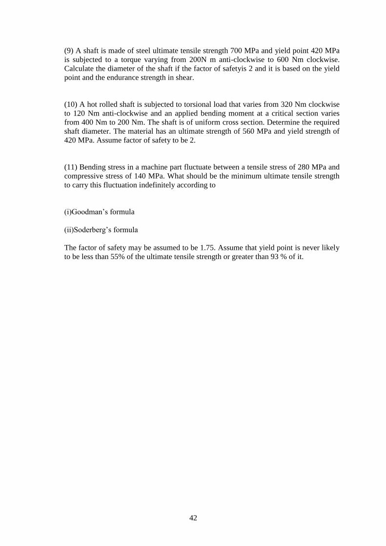
42
(9) A shaft is made of steel ultimate tensile strength 700 MPa and yield point 420 MPa
is subjected to a torque varying from 200N m anti-clockwise to 600 Nm clockwise.
Calculate the diameter of the shaft if the factor of safetyis 2 and it is based on the yield
point and the endurance strength in shear.
(10) A hot rolled shaft is subjected to torsional load that varies from 320 Nm clockwise
to 120 Nm anti-clockwise and an applied bending moment at a critical section varies
from 400 Nm to 200 Nm. The shaft is of uniform cross section. Determine the required
shaft diameter. The material has an ultimate strength of 560 MPa and yield strength of
420 MPa. Assume factor of safety to be 2.
(11) Bending stress in a machine part fluctuate between a tensile stress of 280 MPa and
compressive stress of 140 MPa. What should be the minimum ultimate tensile strength
to carry this fluctuation indefinitely according to
(i)Goodman’s formula
(ii)Soderberg’s formula
The factor of safety may be assumed to be 1.75. Assume that yield point is never likely
to be less than 55% of the ultimate tensile strength or greater than 93 % of it.

43
UNIT- III
DESIGN OF FASTERNERS Temporary Fasteners (Bolted and Screwed Fasteners)
Bolted joints, bolted joint under initial loading, eccentrically loaded Bolted Joints under
different static load conditions.
Permanent Fasteners (Riveted and Welded Fasteners)
Riveted Joints, eccentrically loaded Riveted Joints, Design of Boiler Riveted joints, and
Welding symbols, butt and fillet welds, stress in the welded joints carries tension bending and
shear loading, Design of various types of Welding joints and eccentrically loaded welded
joints under different static load conditions.
Learning objectives: after successful completion of unit – III the student must be able to
19. Explain the Temporary Fasteners, Permanent Fasteners.
20. Discuss different types of bolted joints.
21. Explain importance of bolted joints.
22. Describe procedures for design of bolts with pre-stresses.
23. Discuss design of bolted and riveted joints under eccentric loading.
24. Explain importance of welding.
25. Explain Torsion in welded joints.
26. Calculate strength of welded joints.
27. Explain the eccentrically loaded welded joints under different static load conditions.
Lecture Plan
S.No. Description of Topic No. of Hrs. Method of Teaching
Design of fasteners
1 Temporary Fasteners (Bolted and Screwed
Fasteners), Introduction, Bolted joints,
1 PPT, chalk & board
2 Bolted joint under initial loading,
1 PPT+Video
3 Eccentrically loaded Bolted Joints under
different static load conditions. 2 PPT, chalk & board
4 Tutorials 1 Chalk & board
5 Permanent Fasteners (Riveted and Welded Fasteners),
Introduction, Riveted Joints,
1 PPT+Video
6 Eccentrically loaded Riveted Joints,
1 PPT, chalk & board
7 Design of Boiler Riveted joints, 1 PPT, chalk & board
8 Introduction to welding, Welding symbols,
butt and fillet welds, Stresses in the welded
joints due to tension bending and shear
loading,
2 PPT, chalk & board

44
9 Design of various types of Welding joints
1 PPT+Video
10 Eccentrically loaded welded joints, Welded
joints under different static load conditions. 1 PPT, chalk & board
11 Tutorials 2 Chalk & board
Assignment 3:
(1)A double riveted butt joint, in which the pitch of the rivets in the outer rows is twice that in
the inner rows, connects two 16 mm thick plates with two cover plates each 12 mm thick.
The diameter of the rivets is 22 mm. Determine the pitches of the rivets in the two rows if the
working stresses are not to exceed the following limits:
Tensile stress in plates = 100 MPa, Shear stress in rivets = 75 MPa and bearing
stresses in rivets and plates = 150 MPa.
Make a fully dimensioned sketch of the joint showing atleast two views.
[Question from Set No. 1, Nov. 2005/Regular
Examiniations]
(2)Two lengths of mild steel tie rod having width 200 mm are to be connected by means of
Lozenge joint with two cover plates to withstand a tensile load of 180 KN. Completely design
the joint, if the permissible stresses are 80 MPa in tension, 65 MPa in shear and 160 MPa in
crushing. Draw a neat sketch of the joint.
[Question fromSet No. 2, Nov. 2005/Regular
Examiniations]
(3)A triple riveted lap joint with zig-zag riveting is to be designed to connect two plates of 6
mm thickness. Determine the diameter of the rivet, pitch of rivets and distance between the
rows of the rivets. Indicate how the joint will fail. Also, find the efficiency of the joint. The
permissible stresses are 120 MPa in tension, 100 MPa in shear and 150 MPa in crushing.
[Question fromSet No. 3, Nov. 2005/Regular
Examiniations]
(4)A double riveted double cover butt joint in plates 20-mm thick is made with 25 mm
diameter rivets at 100 mm pitch. The permissible stresses are 120 MPa in tension, 100 MPa
in shear and 150 MPa in crushing. Find the efficiency of joint, taking the strength of the rivet
in double shear as twice than that of single shear.
[Question from Set No. 4, Nov. 2005/Regular
Examiniations]
(5) A double riveted lap joint is made between 15 mm thick plates. The rivet diameter and
pitch are 25 mm and 75 mm respectively. If the ultimate stresses are 400 MPa in tension, 320
MPa in shear and 640 MPa in crushing, find the minimum force per pitch which will rupture
the joint.If the above joint is subjected to a load such that the factor of safety is two, find out
the actual stresses developed in the plates and the rivets.
[Question from Set No. 1, May 2005/Supplementary
Examiniations]

45
(6)Two plates 16 mm thick are joined by a double riveted lap joint. The pitch of each row of
rivets is 90 mm. The rivets are 25 mm in diameter. The permissible stresses are 140 MPa in
tension, 80 MPa in shear and 160 MPa in crushing. Find the efficiency of the joint.
[Question from Set No. 2, May 2005/Supplementary
Examiniations]
UNIT-IV
DESIGN OF FLEXIBLE MECHANICAL ELEMENTS
Belt Drives:
Introduction, classification of belts, belt materials, design of flat (rectangular) belts,
ratio of belt tensions, V-Belts, power transmitted through V-Belt, design of V-Belts.
Springs:
Classification of springs, spring material, Design of helical, leaf, disc and tensional
springs under constant loads and varying loads.
Learning objectives: after successful completion of unit –IV the student must be able to
15. Classify the different types of blets and belt materials
16. Discuss ratio of belt tensions
17. Explain the power transmitted by flat and V-belts
18. Discuss the classification of springs and special features of each.
19. Derive the relations between stress and load & deflection and load for any
type of spring.
20. Describe the design procedure when springs under fatigue loading.
21. Design the helical springs.
Lecture Plan
S.No. Description of Topic No. of
Hrs.
Method of
Teaching
Design of flexible mechanical elements
1 Belt Drives: Introduction, classification of belts,
belt materials, 2 PPT+Video
2 Design of flat belts, ratio of belt tensions, 2
PPT, chalk &
board
3 V-Belts, power transmitted through V-Belt,
Design of V-Belts. 3
PPT, chalk &
board

46
4 Springs: Classification of springs, spring material, 2 PPT+Video
5 Design of helical, leaf, disc and tensional springs
under constant load. 1
PPT, chalk &
board
6 Design of helical, leaf, disc and tensional springs
under varying loads.
2 PPT, chalk &
board
7 Tutorials 2 Chalk & board
Assignment 4:
77. Discuss the classification of springs and special features of each.
78. Derive the relations between stress and load & deflection and load for any type of
spring.
79. Describe the design procedure when springs under fatigue loading.
80. Explain the concept of natural frequency of helical springs.
81. Derive the relations for energy storage capacity for various types of springs.
82. Differentiate the advantages of co-axial springs over other springs.
83. What are the different types of Belt used?
84. State the factors to be considered while selecting belt drive?
85. What is the difference between open and cross belt drive?
86. What are the different materials used for belt drive?
87. Which material is used for flat belt and v belt and rope drive?
88. State advantages & Disadvantages of V-belt over flat belt.
89. What is effect of following action taken are on belt adjusting mechanism.
90. Overtightening of pulley 2] under-tightening of pulley
91. Different between Flat belt and V – belt.
92. Define Angle of lap
93. What is slip in belts ? Write formula for % slip & state effect of slip on power
transmitted.
94. What do you mean by creep in belts ? What is its effect.?
95. What is crowning of pulley ? Why it is done.
96. What is centrifugal tension in belts ? What is its effect on power transmitted ? Write
condition for max power transmitted.
97. What do you mean by initial tension of the belt.
98. Derive expression for ratio of tension on tight side and slack side.
99. Two Parallel shafts are provided with pulleys 480mm and 640 mm diameters and
central distance is 3m. Find the length of 1) Crossed belt 2) Open belt.{Lc=7.843
meters, Lo=7.761 meters}

47
100. Two pulleys having diameters 800mm and 600mm are 8m apart, are
connected by crossed belt drive. Calculate the change in the length if direction of
rotation of the driven pulley to be reversed. {
101. Two Shafts with centre to centre distance between them as 3.5 meters, are having two pulleys with radii equal to 640 mm and 370 mm respectively. Find the length of crossed belt. {Lc=10.46 m B) Problems on slip in belts
102. Find the diameter of driven pulley rotating at 500 rpm if the driver pulley is 250mm in diameter and rotates at 100 rpm by using flat belt drive with 5% slip and the belt thickness is 5 mm. {48.68 mm}
103. A shaft runs at 80 rpm and drives another shaft at 150 rpm through belt drive. the diameter of driving pulley is 600mm . Determine the diameter of the driven pulley taking belt thickness 5mm and slip 4%. {0.3023 m or 302.3mm}
104. The speed of driving pulley is 600 rpm and that of driven pulley is 1800 rpm. If diameter of driving is 500 mm and that of driven is 155 mm. find % slip in belt if belt is 4 mm thick.s= 3.45 %}
105. A spring for a spring balance is required to have deflection of 60mm for a load
of 1500 N. Design the spring assuming spring index 6. Take shear stress as 360 Mpa
and modulus of rigidity as 84 GPa. find free length of spring.
106. Design a spring to take a load of 300 N with spring index 8 and shear stress
400 MPa...The spring should deflect by 15 mm under this load..Take G= 84 GPa.
107. Model QP 3] Design a helical compression spring for a maximum load of
1000 N for a deflection of 25mm using the value of spring index as 5 and Wahl’s
correction factor as 1.3. The maximum permissible shear stress for the spring wire is
400 Mpa and modulus of rigidity 84 KN/mm2.
108. W-2013-8 marks 4] The spring of spring balance, elongates by 150 mm, when
subjected to a load of 400 N. the spring index is 6. Take permissible shear stress for
the wire material 540 MPa and G=84 Gpa..Determine
1) the wire diameter 2) the diameter of Coil 3) No of turns. {W-2010}
109. A helical spring is made from a wire of diameter 6mm diameter and has
outside diameter of 75 mm. If the permissible shear stress is 350 MPa and modulus of
rigidity is 84 kN/mm2. find the axial load which the spring can carry and the
deflection per active turn.
Take Wahl’s correction factor .
{W=383.4 N, {S-2009}
110. A closed coil helical spring is used for an automobile suspension system. The
spring has stiffness 85 N/mm with square and ground ends. The load on the spring

48
causes a total deflection of 9 mm. Taking permissible shear stress 400 MPa spring
index 6 and G=80 GPa.Find,
1) Wire diameter of spring, 2) Length of spring.
111. Design a helical compression spring for a maximum load of 1000 N for a
deflection of 23mm using spring index 5. The maximum permissible shear stress is
420 MPa and modulus of rigidity is 84 GPa.Find the pitch of spring assuming square
and ground ends.
{d=6.3 mm ,D=35 mm,n=13.44 turns, Lf=138.45, p=9.23 mm}S-2012 8
marks Important
112. Design a close coiled helical compression spring for a service load ranging
from 2250 to 2750. The axial deflection of the spring for the load range is 6mm.
Assume a spring index of 5. , Neglect the effect
of stress concentration . Draw fully dimensioned sketch of the spring showing the
details of the finish of the end coils. Assume squared and ground ends.
{ pitch
=13.80mm}
113. Design a helical spring with square and ground ends for a load ranging from
80 N to 145 N when required deflection is 6.5 mm. Take spring index as 8
,permissible shear stress for the wire material 475 MPa and G=84 Gpa.
{ pitch
=6.19mm}
114. Design and draw a valve spring of a petrol engine for the following operating
conditions :
Spring load when the valve is open = 400 N
Spring load when the valve is closed = 250 N
Maximum inside diameter of spring = 25 mm
Length of the spring when the valve is open = 40 mm
Length of the spring when the valve is closed = 50 mm
Maximum permissible shear stress = 400 MPa
UNIT-V
DESIGN OF SHAFTS AND KEYS
Transmission shafts, Design of solid and hollow shafts based on strength, rigidity and
Flexible shafts, shaft and axles – key and classification of keys, stresses in the keys, design
considerations, effect of key way on the shaft strength.
Learning objectives: after successful completion of unit –V the student must be able to
13 Explain the Transmission shafts
14 Design of solid and hollow shafts based on strength and rigidity
15 Discuss about different types of keys and their function

49
16 Explain the different types of stresses developed in keys
17 Enumerate the design considerations of keys
18 Explain the effect of key way on the shaft strength.
Lecture Plan
S.No. Description of Topic No. of Hrs. Method of Teaching
Design of shafts and Keys.
1 Introduction to Transmission shafts, 1 PPT+Video
2 Design of solid and hollow shafts based on
strength and rigidity 2 PPT, chalk & board
3 Flexible shafts, shaft and axles. 1 PPT, chalk & board
4 Introduction to key and classification of keys, 1 PPT+Video
5 Stresses in the keys, Design considerations, 2 PPT, chalk & board
6 Effect of key way on the shaft strength 1 PPT, chalk & board
7 Tutorials 2 PPT, chalk & board
Assignment 5:
15. Explain the effect of key way on the strength of a shaft.
16. Write the comparison between solid shafts, hollow shafts and spindles.
17. A shaft is required to transfer 43KW of power at 600 rpm. The outside diameter must not
exceed 50 mm and the maximum shear stress is not to exceed 70 N/mm2. Find out the
dimensions of hollow and solid shaft, which would meet their requirements. Also compare
their weights.
18. Compute the diameter of a solid shaft which has to transmit 16KW power at 300 rpm.
Ultimate shear stress per shaft material is 350 N/mm2 and factor of safety for design is 6. If
a hollow shaft replaces the solid shaft, find the inside and outside diameters if the ratio is
0.5.
19. A shaft is supported by two bearings placed 1.2 m apart. A 600 mm diameter pulley is
mounted at a distance of 300mm to the right of left hand bearing and this drives a pulley
directly below it with the help of a belt having maximum tension of 2kN. Another pulley
400 mm diameter is placed 200 mm to the left hand bearing and is driven with the help of
an electric motor and belt which is placed horizontally to the right. The angle of contact for
both the pulleys is 1800
and coefficient of friction is 0.24. Calculate the diameter of the shaft
taking working stresses of 63 Mpa in tension and 42 Mpa in shear.
20. A shaft running at 400 rpm transmits 10 kW. Assuming allowable shear stress in shaft is 40
Mpa, find the diameter of the shaft.
21. Determine the diameter of the hollow shaft with inside dia = 0.6 outside dia. The shaft is
driven by an overhung pulley of 90 cm diameter. Take weight of pulley is 60 kg, the belt
tensions as 290 and 100 kg, over hang= 25 cm, angle of lap is 1800.

50
VNR VIGNANA JYOTHI INSTITUTE OF ENGINEERING & TECHNOLOGY
(Autonomous)
DEPARTMENT OF MECHANICAL ENGINEERING
III B. Tech, Ist Semester (Mechanical Engineering)
Subject : Production Technology
Subject Code : 13MED009
Academic Year : 2016 – 17
Number of working days : 90
Number of Hours / week : 3 + 1
Total number of periods planned:78
Name of the Faculty Member: Mr.M.S.Srinivasa Rao.
Course Objectives:
Identify various tools required to make a mold, types of casting methods used to make
casting.
Explain the various welding techniques used in metal joining processes
Understand the importance of basic metal working processes like rolling, forging,
extrusion etc.
Understand the various molding techniques used to make a plastic components
Course Outcomes (COs): Upon completion of this course, students should be able to:
CO-1: Define fundamental concepts of production processes as applied to
Mechanical engineering applications.
CO-2: Discuss various casting methods, welding techniques and metal forming
processes.
CO-3: Apply the various above processes are required to make a component based on
their applications.
CO-4: Evaluate the various assumptions made in the design of components to avoid
the common pitfalls
UNIT : I
Syllabus: CASTING: Steps involved in making a casting; Advantage of casting and its applications; Pattern and
core making; Types of patterns – Materials used for patterns; Pattern allowances and their
construction; Principles of Gating, Gating ratio and design of gating systems.
Solidification of casting; Concept; Solidification of pure metal and alloys; Risers; Types;
Function and design; Casting design considerations; Quality testing and inspection of
castings; Special casting processes; Centrifugal, Die, Investment casting; Melting furnaces.
Learning Objectives: After completion of the unit, the student must able to:
Explain various types of tools required to make patterns, moulds
Describe various types of pattern materials used in casting
Differentiate between pattern and casting

51
Various types of patterns allowances and its importance
Explain about different types of gates, solidification of pure metals and alloys
Explain about various functions of runners and risers
Explain about various casting design considerations
Discuss various types of special casting processes
Lecture Plan
S.No. Description of Topic No. of Hrs. Method of Teaching
1. Introduction about the casting, welding and
other mfg. processes
1st & 2
nd hour PPT + Video
2. Types of Tools used in sand casting technique 3rd
& 4th
hour Black board + PPT
3. Types of patterns, pattern materials 5th
hour Black board
4. Pattern allowances 6th
hour Black board + Video
5. Materials used for patterns 7th
hour Black board
6. Types of cores, functionality 8th
hour Black board + PPT
7. Types of gates, gating ratio 9th
& 10th
hour Black board + Video
8. Design of Gating system, advantages and
applications of castings
11th
hour Black board + PPT
9. Solidification of pure metal and alloys 12th
hours Black board + Video
10. Types of risers and its fuctionality 13th
& 14th
hour Black board
11. Casting design considerations 15th
& 16th
hour Black board
12 Testing and inspection of castings 17th
& 18th
hour Black board + PPT
13 Special casting processes 19th
& 20th
hour Black board + PPT
14 Melting furnaces 21st & 22
nd hour Black board + PPT
Assignment – 1
1. Types of tools used in sand casting.
2. Types of pattern allowances, pattern materials.
3. Define pattern and core.
4. Elements of a gating system.
5. Write any three Functions of a runner and a riser.
6. List out various types of cores used in casting.
7. What are the advantages of casting and its applications
8. What are the various casting design considerations
9. What are the special casting technique processes and explain with a neat sketch
investment casting process
10.Draw a neat sketch of Cupola furnace and its advantages
UNIT : II
Syllabus: WELDING:
Classification of welding process types of welds and welded joints and their characteristics,
design of welded joints, Gas welding, ARC welding, Forge welding, resistance welding,

52
Thermit welding and Plasma welding Inert Gas welding, TIG & MIG, welding, Friction stir
welding, Induction welding, Explosive welding, Laser welding, Soldering & Brazing. Heat
affected zones in welding; welding defects – causes and remedies – destructive and
nondestructive testing of welds.
Learning Objectives: After completion of the unit, the student must able to:
Explain various types of welding processes
Describe various types of welded joints
Explain about advantages and limitations of welded joints
Differentiate between pressure welding and fusion welding
Explain about various Gas welding techniques
Differentiate between TIG welding and MIG welding
Explain about various welding defects
Describe soldering and brazing techniques
Lecture Plan
S.No. Description of Topic No. of Hrs. Method of Teaching
1. Introduction about welding 1st hour PPT + Video
2. Classification of Welding processes 2nd
hour Black board + PPT
3. Differences between pressure welding and
fusion welding, principle of arc welding
3rd
& 4th
hour Black board + PPT
4. Arc welding equipment and accessories 5th
hour Black board + Video
5. Types of electrodes and its functions 6th
hour Black board
6. Principle of gas welding and its accessories 7th
hour Black board + Video
7. Types of flames 8th
hour Black board + PPT
8. Gas welding techniques 9th
hour Black board + PPT
9. TIG welding 10th
hour Black board + Video
10. MIG welding 11th hour
Black board + PPT
11. Types of Resistance welding processes 12th
& 13th
hour Black board
12 Modern welding methods: ultrasonic welding 14th
& 15th
hour Black board + PPT
13 Co2 welding 16th
hour Black board + PPT
14 Atomic hydrogen welding 17th
hour Black board
15 Submerged arc welding 18th
hour Black board + PPT
16 Welding defects , causes and remidies 19th
& 20th
hour Black board + PPT
17 Soldering and brazing 21st hour Black board
Assignment – 2
1. Classification of welding processes
2. Differentiate between fusion welding and pressure welding
3. Write the principle of arc welding.
4. What are the functions of electrodes?
5. Types of flames in gas welding

53
6. Give the list of equipment necessary for gas welding
7. Different types of welding techniques used in gas welding
8. What are the various welding defects, causes and remidies
9. Write short notes on soldering and brazing.
10. Differentiate between TIG welding and MIG welding
UNIT : III
Syllabus:
MECHANICAL WORKING -1:
Hot working; Cold working; Strain hardening; Recovery; Recrystallisation and grain growth;
Comparison of properties of cold and hot worked parts
ROLLING: Rolling fundamentals; Theory of rolling; Types of Rolling mills and products; Forces in
rolling and power requirements.
EXTRUSION: Basic extrusion process and its characteristics; Hot extrusion and Cold extrusion; Forward
extrusion and backward extrusion – Impact extrusion; Hydrostatic extrusion; Extrusion
defects.
FORGING PROCESSES: Principles of Forging; Tools and dies; Types of Forging; Smith forging; Drop Forging; Roll
Forging; Forging hammers; Rotary Forging; Forging defects.
Learning Objectives: After completion of the unit, the student must able to:
Explain various types of metal forming processes
Describe recovery, Recrystallisation and grain growth
Differentiate between hot working and cold working process
Explain about theory of rolling
Discuss about types of rolling milling and their products
Explain about types of extrusion processes and its defects
Describe principle of forging
Describe various types of forging techniques
Explain various forging defects
Lecture Plan
S.No. Description of Topic No. of Hrs. Method of Teaching
1. Introduction about metal forming 1st hour PPT + Video
2. Recovery, Recrystallisation and grain
growth, strain hardening
2nd
hour & 3rd
hour Black board + PPT
3. Differences between hot working and
cold working
4th
hour
Black board + PPT
4. Theory of rolling, rolling products 5th
hour Black board + PPT
5. Types of rolling mills 6th
hour Black board + PPT

54
6. Forces in rolling mills and power
requirements
7th
hour Black board
7. Introduction about extrusion 8th
hour Black board + PPT
8. Types of extrusion processes 9th
hour & 10th
hour Black board + Video
9. Extrusion defects 11th
hour Black board + Video
10. Introduction about forging, forging tools 12th
hour Black board + PPT
11. Types of forging processes 13th
hour & 14th
hour Black board
12 Forging hammers 15th
hour & 16th
hour Black board + PPT
13 Forging defects 17th
hour Black board + PPT
14 Applications of Forging 18th
hour Black board + PPT
Assignment – 3
1. Define hot working and cold working
2. Define recovery, recrystallisation and grain growth
3. Differentiate between hot working and cold working
4. Theory of rolling & rolling products
5. Types of rolling mills
6. Define extrusion and its advantages
7. Classification of extrusion processes
8. Hydrostatic extrusion process and its merits
9. Extrusion defects.
10. What is meant by forging
11. Forging applications
12. Forging hammers
13. Forging defects
UNIT : IV
Syllabus: MECHANICAL WORKING -2:
Stamping, forming and other cold working processes : Blanking and piercing; Bending and forming;
Drawing and its types; Wire drawing and Tube drawing; Coining; Hot and cold spinning; Types of
presses and press tools; Forces and power requirement in the above operations.
Learning Objectives: After completion of the unit, the student must able to:
Explain various types of metal forming processes
Describe various sheet metal operations
Describe with a neat sketch wire drawing and tube drawing
Explain about spinning process
Discuss about types of presses and press tools
Lecture Plan
S.No. Description of Topic No. of Hrs. Method of Teaching

55
1. Introduction about sheet metal operations 1st hour Black board
2. Differences between blanking and
piercing
2nd
hour Black board + PPT
3. Drawing and its types 3rd
hour & 4th
hour
Black board + PPT
4. Wire drawing and tube drawing 5th
hour Black board + PPT
5. Types of presses and press tools 6th
hour & 7th
hour Black board + PPT
6. Forces and power requirements 8th
hour & 9th
hour Black board
Assignment – 4
1. Different types of sheet metal operations
2. Differentiate between hot working and cold working
3. Explain with a neat sketch wire drawing and tube drawing
4. Write short notes on spinning
5. List out various types of presses and press tools.
UNIT : V
Syllabus:
PLASTIC MATERIALS AND PROCESSES:
Types of plastics; Compression moulding; Injection moulding; Blow moulding; Film and
Sheet forming; Thermoforming.
Learning Objectives: After completion of the unit, the student must able to:
Explain types of plastic materials
Describe types of molding processes
Describe with a neat sketch injection molding
Explain with a neat sketch blow molding
Discuss about thermoforming process
Lecture Plan
S.No. Description of Topic No. of Hrs. Method of Teaching
1. Introduction about plastics 1st hour Black board + Video
2. Advantages of plastics 2nd
hour Black board + PPT
3. Types of plastics and applications 3rd
hour & 4th
hour
Black board + PPT
4. Injection molding 5th
hour Black board + PPT
5. Blow molding 6th
hour Black board + PPT
6. Thermoforming 7th
hour Black board
7 Diff. between thermo plastics and
thermosetting plastics
8th
hour Black board + PPT
Assignment – 5

56
1. Different types of sheet metal operations
2. Differentiate between hot working and cold working
3. Explain with a neat sketch wire drawing and tube drawing
4. Write short notes on spinning
5. List out various types of presses and press tools.
TEXT BOOKS
T1 – Manufacturing Technology by P.N.Rao
REFERENCES:
R1 –Production Technology by R.K.jain
R2 – Production technology by PC Sharma
R3 - Manufacturing Engineering and Technology by Kalpak Jian S
R4 - Process and Materials of Manufacturing by Lindberg/PE
R5 - Principles of Metal Castings by Rosenthal
R6 - Welding Process by Parmar

57
VNR VIGNANAJYOTHI INSTITUTE OF ENGINEERING AND TECHNOLOGY
BACHUPALLY, NIZAMPET (S. O.), BACHUPALLY, HYDERABAD- 500 090
DEPARTMENT OF MECHANICAL ENGINEERING
Name of the Staff: P.Prasad kumar / L.Sandeep Raj Subject:
TURBOMACHINERY
Code: 13MED013 Course: B. Tech (Mechanical
Engineering)
Year & Semester: III B.Tech. & I Semester Academic Year: 2016-2017
III Year B.Tech ME I Sem L T/P/D C
3 1 3
13MED013 TURBOMACHINERY
Course Prerequisites: Mathematics, Engineering Basics, Thermal Engineering
Basics
Course Objectives:
Understand various energy conversations that take place in a turbo machines.
Understand the principles of turbo machines.
Understand governing mathematical equations to perform theoretical calculations.
Learning Outcomes:
Students will be able to:
Model and analyze problems in turbo machines.
Design a simple energy producing or effort reducing device using basic thermodynamics
concepts.
Suggest and improvements to minimize losses.
List of Text Books:
T1- Thermal Engineering by Rathore; Publisher: Tata McGraw Hill.
List of Reference Books:
R1 – Gas Turbines by V. Ganesan; Publisher: Tata McGraw Hill.
R2 -- Thermal Engineering by R.K Rajput; Publisher: Lakshmi Publications.
R3 -- Thermal Engineering by P. L. Ballaney; Publisher: Khanna.
R4 -- Fundamentals of Turbo Machinery by B. K. Venkanna; Publisher: Prentice Hall
International.
R5 – Steam and Gas Turbines by R.Yadav; Central Publishing House
UNIT I
STEAM GENERATORS:
Introduction, Classification of Boilers , Working Principles of Fire Tube and Water Tube Boilers, Low
Pressure boilers, High Pressure Boilers – Babcock and Wilcox , Lamont Boiler, Boiler draught and
performance of boilers, Equivalent evaporation.
STEAM CONDENSORS:
Introduction, purpose and types of condensers. Efficiency of condenser, air pumps.
Learning Objectives: 1. Classify boilers 2. Understand working principles of different boilers 3. Define boiler performance parameters 4. Understand working of a chimney 5. Define efficiency of chimney 6. Understand different draughts 7. Understand importance of steam condensers and classify them

58
8. Define vacuum efficiency and condenser efficiency 9. Understand the working of air pump
Lecture Plan:
S. No. Topic Name
Reference
Books,
Mode of
Teaching
Number
of
Periods
Cumulati
ve
Periods
UNIT-I Steam Generators and Steam Condensers:
1 Boilers: Classification – Working principles –
Fire tube and Water tube.
T1,R2,R3,
PPT, Video
2 2
2 L.P and H.P boilers -- Babcock and Wilcox ,
Lamont Boiler
T1,R2,R3,
PPT, Video
2 4
3
Boiler draught T1,R2,R3,
PPT, Chalk
& Talk
3 7
4
Performance of boilers, Equivalent evaporation T1,R2,R3,
Chalk &
Talk
2 9
5 STEAM CONDENSORS:
Introduction, purpose and types of condensers
T1,R2,R3,
PPT 2 11
6
Efficiency of condenser, air pumps.
T1,R2,R3,
PPT, Chalk
& Talk
3 14
UNIT II
STEAM NOZZLES:
Functions of nozzle, applications, types, flow through nozzles, Thermodynamic analysis, assumptions,
velocity at nozzle exit, Ideal and actual expansion in nozzle, velocity co-efficient, condition for
maximum discharge, nozzle efficiency, Critical pressure ratio, Supersaturated flow and its effects,
degree of super saturation, degree of under cooling, wilson line.
Learning Objectives: After successful completion of Unit – II the student must be able to
1. Understand the functions and applications of nozzles 2. Analyze the nozzles 3. Define velocity co-efficient 4. Obtain condition for maximum discharge 5. Define critical pressure ratio 6. Define degree of saturation and degree of under cooling
Lecture Plan:
S. No. Topic Name
Reference
Books,
Mode of
Teaching
Number
of
Periods
Cumulati
ve
Periods
UNIT – II Steam Nozzles
1
Steam Nozzles: Function of nozzle – applications
- types, Flow through nozzles,
T1,R2,R3,
PPT, Chalk
& Talk
2 2
2 Thermodynamic analysis – assumptions -velocity
of nozzle at exit-Ideal and actual expansion in
T1,R2,R3,
Chalk & 4 6

59
nozzle, velocity coefficient, condition for
maximum discharge, critical pressure ratio,
criteria to decide nozzle shape
Talk
3 Super saturated flow, its effects. T1,R2,R3,
PPT
1 7
4 Degree of super saturation and degree of under
cooling - Wilson line
T1,R2,R3,
PPT
2 9
UNIT III
STEAM TURBINES:
Impulse turbine - Mechanical details, velocity diagram, effect of friction, power developed, axial
thrust, diagram efficiency, Condition for maximum efficiency, Methods to reduce rotor speed - velocity
compounding, pressure compounding, combined velocity and pressure compounding, velocity and
pressure variation along the flow.
Reaction Turbine - Mechanical details, principle of operation, Thermodynamic analysis of a stage,
Degree of reaction, velocity diagram, parson’s reaction turbine, condition for maximum efficiency.
Learning Objectives: After successful completion of Unit – III the student must be able to
1. Classify steam turbines 2. Understand effect of friction 3. Understand methods to reduce rotor speed -- compounding 4. Calculate turbine power output. 5. Define diagram efficiency, Stage efficiency. 6. Understand principle of reaction turbine 7. Define degree of reaction 8. Draw velocity diagrams
9. Derive the condition for maximum efficiency.
Lecture Plan:
S. No. Topic Name
Reference
Books,
Mode of
Teaching
Number
of
Periods
Cumulati
ve
Periods
UNIT III Steam Turbines:
1
Steam Turbines: Classification. Impulse turbine:
Mechanical details
T1,R2,R3,
R5, PPT,
Video
1 1
2
Velocity diagram – effect of friction – power
developed, axial thrust, blade or diagram
efficiency – condition for maximum efficiency.
T1,R2,R3,
R5, PPT,
Chalk &
Talk
2 3
3
Methods to reduce rotor speed-Velocity
compounding and pressure compounding
combined velocity and pressure compounding.
T1,R2,R3,
R5, PPT,
Chalk &
Talk
3 6
4
Velocity and Pressure variation along the flow T1,R2,R3,
R5, PPT,
Chalk &
Talk
1 7
5 Reaction Turbine : Mechanical details –
principle of operation, thermodynamic analysis of
T1,R2,R3,
R5, PPT, 2 9
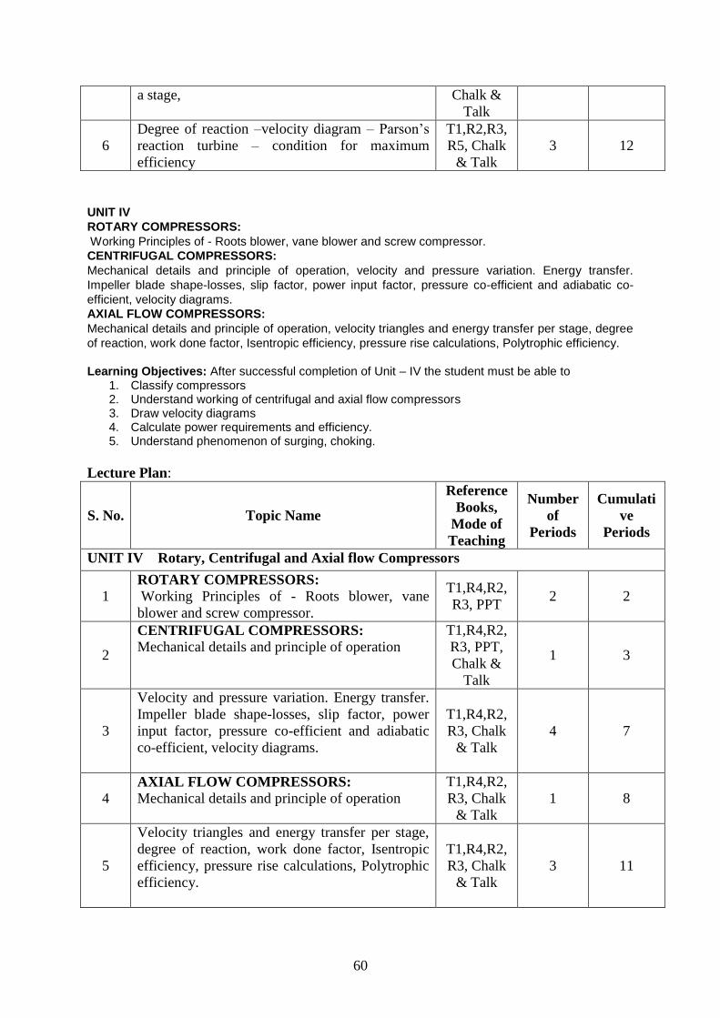
60
a stage, Chalk &
Talk
6
Degree of reaction –velocity diagram – Parson’s
reaction turbine – condition for maximum
efficiency
T1,R2,R3,
R5, Chalk
& Talk
3 12
UNIT IV
ROTARY COMPRESSORS:
Working Principles of - Roots blower, vane blower and screw compressor.
CENTRIFUGAL COMPRESSORS:
Mechanical details and principle of operation, velocity and pressure variation. Energy transfer.
Impeller blade shape-losses, slip factor, power input factor, pressure co-efficient and adiabatic co-
efficient, velocity diagrams.
AXIAL FLOW COMPRESSORS:
Mechanical details and principle of operation, velocity triangles and energy transfer per stage, degree
of reaction, work done factor, Isentropic efficiency, pressure rise calculations, Polytrophic efficiency.
Learning Objectives: After successful completion of Unit – IV the student must be able to
1. Classify compressors 2. Understand working of centrifugal and axial flow compressors 3. Draw velocity diagrams 4. Calculate power requirements and efficiency. 5. Understand phenomenon of surging, choking.
Lecture Plan:
S. No. Topic Name
Reference
Books,
Mode of
Teaching
Number
of
Periods
Cumulati
ve
Periods
UNIT IV Rotary, Centrifugal and Axial flow Compressors
1 ROTARY COMPRESSORS:
Working Principles of - Roots blower, vane
blower and screw compressor.
T1,R4,R2,
R3, PPT 2 2
2
CENTRIFUGAL COMPRESSORS:
Mechanical details and principle of operation
T1,R4,R2,
R3, PPT,
Chalk &
Talk
1 3
3
Velocity and pressure variation. Energy transfer.
Impeller blade shape-losses, slip factor, power
input factor, pressure co-efficient and adiabatic
co-efficient, velocity diagrams.
T1,R4,R2,
R3, Chalk
& Talk
4 7
4 AXIAL FLOW COMPRESSORS:
Mechanical details and principle of operation
T1,R4,R2,
R3, Chalk
& Talk
1 8
5
Velocity triangles and energy transfer per stage,
degree of reaction, work done factor, Isentropic
efficiency, pressure rise calculations, Polytrophic
efficiency.
T1,R4,R2,
R3, Chalk
& Talk
3 11

61
UNIT V
GAS TURBINES:
Classification of Gas Turbines ,Ideal cycle, essential components ,parameters of performance, actual
cycle , regeneration ,inter cooling and reheating, closed and semi closed cycles, merits and demerits,
combustion chambers and turbines for Gas Turbine plants.
JET PROPULSION:
Principle of operation, Classification of Jet propulsion engines, working principles with schematic
diagram and representation on T-s diagram, Thrust, Thrust power and propulsion efficiency. Needs
and demands met by Turbo Jet Engines, Schematic diagram, Thermodynamic cycle, performance
evaluation thrust augmentation methods.
ROCKETS:
Application - working principle, Classification, Propellant type, Thrust, Propulsive efficiency – Specific
impulse, solid and liquid propellant Rocket Engines.
Learning Objectives: After successful completion of Unit – V the student must be able to
1. Classify gas turbines 2. Understand regeneration and reheating 3. Differentiate between closed and open cycle gas turbines 4. Find performance of gas turbine power plant 5. Understand principles of jet propulsion 6. Classify jet propulsive engines 7. Define thrust power and propulsive efficiency 8. Understand working principle of rockets 9. Classify rockets 10. Define efficiency and specific impulse of rockets
Lecture Plan:
S. No. Topic Name
Reference
Books,
Mode of
Teaching
Number
of
Periods
Cumulati
ve
Periods
UNIT V Gas Turbines, Jet Propulsion and Rockets
1
Gas Turbines: Classification of gas turbines,
Ideal cycle, essential components.
T1,R1,R4,
R5, PPT,
Video
1 1
2
Parameters of performance, actual cycle,
regeneration, inter cooling and reheating.
T1,R1,R4,
R5, Chalk
& Talk
2 3
3
Closed and Semi-closed cycles, merits and
demerits.
T1,R1,R4,
R5, Chalk
& Talk
2 5
4
Combustion chambers and turbines of Gas
Turbine Plant.
T1,R1,R4,
R5, Chalk
& Talk
2 7
5 Jet Propulsion: Principle of Operation,
Classification of jet propulsive engines
T1,R1,R4,
R5, PPT 1 8
6
Working Principles with schematic diagrams and
representation on T-S diagram, Thrust, Thrust
Power and Propulsion Efficiency
T1,R1,R4,
R5, PPT 2 10
7
Needs and Demands met by Turbo jet engines,
Schematic Diagram, Thermodynamic Cycle
T1,R1,R4,
R5, PPT,
Chalk &
Talk
1 11

62
8
Performance Evaluation Thrust Augmentation –
Methods.
T1,R1,R4,
R5, Chalk
& Talk
1 12
9
Rockets: Application, Working Principle,
Classification, Propellant Types
T1,R1,R4,
R5, Chalk
& Talk
1 13
10
Propulsive efficiency – Specific impulse, solid
and liquid propellant Rocket Engines.
T1,R1,R4,
R5, Chalk
& Talk
2 15