VNAMaster - Welcome to Livingston, The Leading Test ... · PDF filemanufacturing to measure...
12
VNA Master ™ MS2024A/MS2026A Handheld Vector Network Analysis from 2 MHz to 6 GHz VNA Master ™ MS2024A/MS2026A Handheld Vector Network Analysis from 2 MHz to 6 GHz
Transcript of VNAMaster - Welcome to Livingston, The Leading Test ... · PDF filemanufacturing to measure...

VNA Master™
MS2024A/MS2026AHandheld Vector Network Analysis from 2 MHz to 6 GHz
VNA Master™
MS2024A/MS2026AHandheld Vector Network Analysis from 2 MHz to 6 GHz

2
Make fast and accurate measurements anywhere withVNA Master MS2024A/MS2026AVNA Master MS2024A and MS2026A are the most advanced ultraportable handheld VNAs on the market featuring unparalleledperformance at modest prices.
The new VNA Master is a handheld Vector Network Analyzer designedto make accurate vector corrected 1-port and 1-path 2-port magnitudeand phase measurements from 2 MHz to 4 GHz (MS2024A) and 2 MHzto 6 GHz (MS2026A). The MS2024A and MS2026A take advantage ofthe latest DSP processors technology enabling very fast measurementsfor both Return Loss and Distance-To-Fault measurements. High andLow power settings for 2-port measurements eliminate the need forexternal attenuators when performing direct gain measurements. UsingAnritsu’s precision components, better than 42 dB of correcteddirectivity can be obtained over the entire frequency range. Theinternal memory can store more than 1000 traces and setups andinformation can easily be transferred to a computer using either amemory card, an Ethernet connection, or the USB connection.
The MS2024A and MS2026A’s wide frequency range and overallperformance find applications in multiple markets. Providing 1-portand 2-port coverage down to 2 MHz fills a requirement formilitary/defense applications and eliminates the need for bench topVNAs in the field for S11 and S21 measurements. Both themilitary/defense and commercial wireless markets will appreciate theVNA Master’s portable Frequency Domain Reflectometry (FDR) basedReturn Loss and DTF measurements to verify system performance andlocate degradations and faults in cable and antenna systems. Generalpurpose VNA customers looking for an economical solution to makeaccurate S11 and S21 measurements need to look no more.
Making It EasyComing from the industry leader in cable and antenna analysis, it’sno surprise that the MS2024A and MS2026A are incredibly easy tooperate requiring little or no training. Depending on the applicationthe Measurement menu can be changed to provide Field (Return Loss)or VNA (S11 Log Magnitude) menus. A full range of markers can beused to enable easier interpretation of the measurement data. LimitLines further simplify procedures, allowing the user to create quickand simple pass/fail tests. The VNA Master comes packed with menus ineight languages (expandable to ten).
Practical and Ready to RollWeighing less than 6.4 pounds including the battery, the MS2024Aand MS2026A are light enough to take anywhere. Better still, they easilywithstand the rough and tumble of day-to-day punishment. The three-hour battery life allows plenty of time to complete most testing.Replacing the battery takes no time at all, and no tools.
Powerful, Portable and Ready to Perform

3
VNA Master is the most advanced 2 MHz to 6 GHzHandheld Vector Network Analyzer on the market
Many Features Many More BenefitsVNA Menu S11/S21 Log Magnitude, S11/S21 Phase, S11 Smith Chart, S11
VSWR, Fault Location Field Menu Return Loss, VSWR, Cable Loss, DTF RL/VSWR, 2-Port Gain, 1-Port
Phase, 2-Port Phase, Smith ChartSelectable output power for 2-port measurements No need for external attenuators when measuring gain of active
devices.Powerful Processors Save time while performing frequency sweeps and DTF
measurements.RF Immunity Reject unwanted signals in RF rich environments.
Built-in Variable Bias Tee Deliver +12V to +24V in 3V steps to the center pin of the RF In port. No need for external supply to bias active devices.
Lightweight (<6.4 lbs., including battery) Instrument is light enough to carry anywhere
Field Replaceable three-hour battery Maintain high productivity on a single battery; and replace the battery,without tools in seconds.
Multiple Markers Display up to six markers on screen, each with delta marker capability,to get the exact reading.
Signal Standard/Cable Standard Editor Add signal and cable standards that are not part of the standard lists.
Eight Built-in Languages English, Spanish, Italian, French, German, Japanese, Korean, Chinese,and two customized languages.
Memory Storage and Data Transfer Store more than 1000 traces in memory. Transfer data to a PC usingEthernet, USB, or Memory Card.
Date & Time
InstrumentSettings
Summary
FunctionsHard Keys
BatteryAccess
On/Off
Soft Keys
DirectionalButtons
Rotary Knob
Soft KeyActiveFunctionBlock
DualFunctionKeypad
ExternalPower
RF InRF OutRF DetectorConnector
GPS AntennaConnector
USBInterface
CompactFlash Slot
LANConnector

4
Return Loss
Cable Loss
Distance-To-Fault
Convenient VNA Measurements Anywhere, Anytime
VNA Master performs a variety of RF measurements aimed at simplifying thetask for the technician and engineer. A single key selection on the bottom hardkeys brings up all the RF measurements you need, whether you are performingflightline test, cable and antenna maintenance, or S-parameters in the lab.
Frequency Domain Reflectometry (FDR)TDR (Time Domain Reflectometry) is based on a DC pulse, providing no energy for the RF bands making it impractical tolocate degradations and faults at RF frequencies. VNA Master’s DTF measurement is based on a swept RF signal and is idealfor detecting faults and degradations in the RF bands. FDR (Frequency Domain Reflectometry) can be used to characterizesystems using frequency selective devices (filters, duplexers, lightning arrestors, antennas, combiners), thus providing anearly alert to devastating system failures. Plus, FDR can track down costly, time consuming problems due to corrosion, slightpin gaps and damaged RF components. By breaking away from the traditional fix-after-failure maintenance process,FDR techniques find small, hard-to-identify problems before they become big problems by testing the system at theoperating frequency.
S11 Log Magnitude/Return Loss/VSWRVNA Master’s S11 measurements can be used in the lab or inmanufacturing to measure the match of attenuators, antennas,cables, filters, amplifiers, or any other passive and active components.In the field, Return Loss is used to characterize cable and antennasystems to ensure conformance to system specific requirements. MS2024Aand MS2026A display reflection measurements both in dB and linearly inthe form of VSWR. Using Master Software Tools, rho or reflectioncoefficient is another linear display option.
Cable LossCable Loss measures the energy lost in the cable or transmission line. It isa field measurement usually performed with a short or open at the end ofthe cable. Since the absorbed RF energy is frequency dependent, VNAMaster also displays the average cable loss over the given frequency range.
Distance-To-Fault (DTF)VNA Master’s Distance-To-Fault (DTF) measurement is used in the field toprecisely locate faults within cable and feedline systems by displayingmagnitude discontinuities in dB or VSWR over distance in meters or feet.The DTF display is obtained by performing a sweep in the frequencydomain and then by using the inverse Fast Fourier Transform, the data isconverted to the time domain. Different windowing (frequency filters)types give the user the flexibility to trade off sidelobes for pulse width.
2-Port Magnitude and Phase Measurements from 2 MHz to 6 GHz
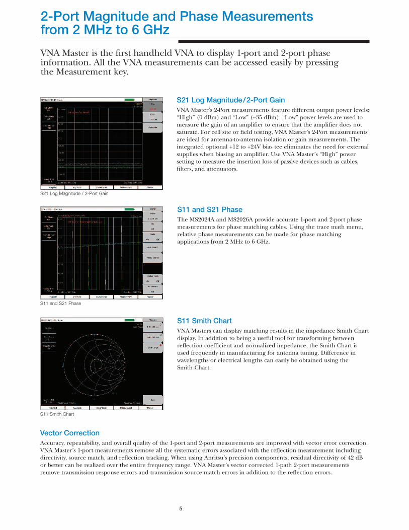
VNA Master is the first handheld VNA to display 1-port and 2-port phaseinformation. All the VNA measurements can be accessed easily by pressingthe Measurement key.
5
S21 Log Magnitude / 2-Port Gain
S11 and S21 Phase
S11 Smith Chart
Vector CorrectionAccuracy, repeatability, and overall quality of the 1-port and 2-port measurements are improved with vector error correction.VNA Master’s 1-port measurements remove all the systematic errors associated with the reflection measurement includingdirectivity, source match, and reflection tracking. When using Anritsu’s precision components, residual directivity of 42 dBor better can be realized over the entire frequency range. VNA Master’s vector corrected 1-path 2-port measurementsremove transmission response errors and transmission source match errors in addition to the reflection errors.
S21 Log Magnitude/2-Port GainVNA Master’s 2-Port measurements feature different output power levels:“High” (0 dBm) and “Low” (–35 dBm). “Low” power levels are used tomeasure the gain of an amplifier to ensure that the amplifier does notsaturate. For cell site or field testing, VNA Master’s 2-Port measurementsare ideal for antenna-to-antenna isolation or gain measurements. Theintegrated optional +12 to +24V bias tee eliminates the need for externalsupplies when biasing an amplifier. Use VNA Master’s “High” powersetting to measure the insertion loss of passive devices such as cables,filters, and attenuators.
S11 and S21 PhaseThe MS2024A and MS2026A provide accurate 1-port and 2-port phasemeasurements for phase matching cables. Using the trace math menu,relative phase measurements can be made for phase matchingapplications from 2 MHz to 6 GHz.
S11 Smith ChartVNA Masters can display matching results in the impedance Smith Chartdisplay. In addition to being a useful tool for transforming betweenreflection coefficient and normalized impedance, the Smith Chart isused frequently in manufacturing for antenna tuning. Difference inwavelengths or electrical lengths can easily be obtained using theSmith Chart.
6
VNA Master is a Multiple Purpose Instrument
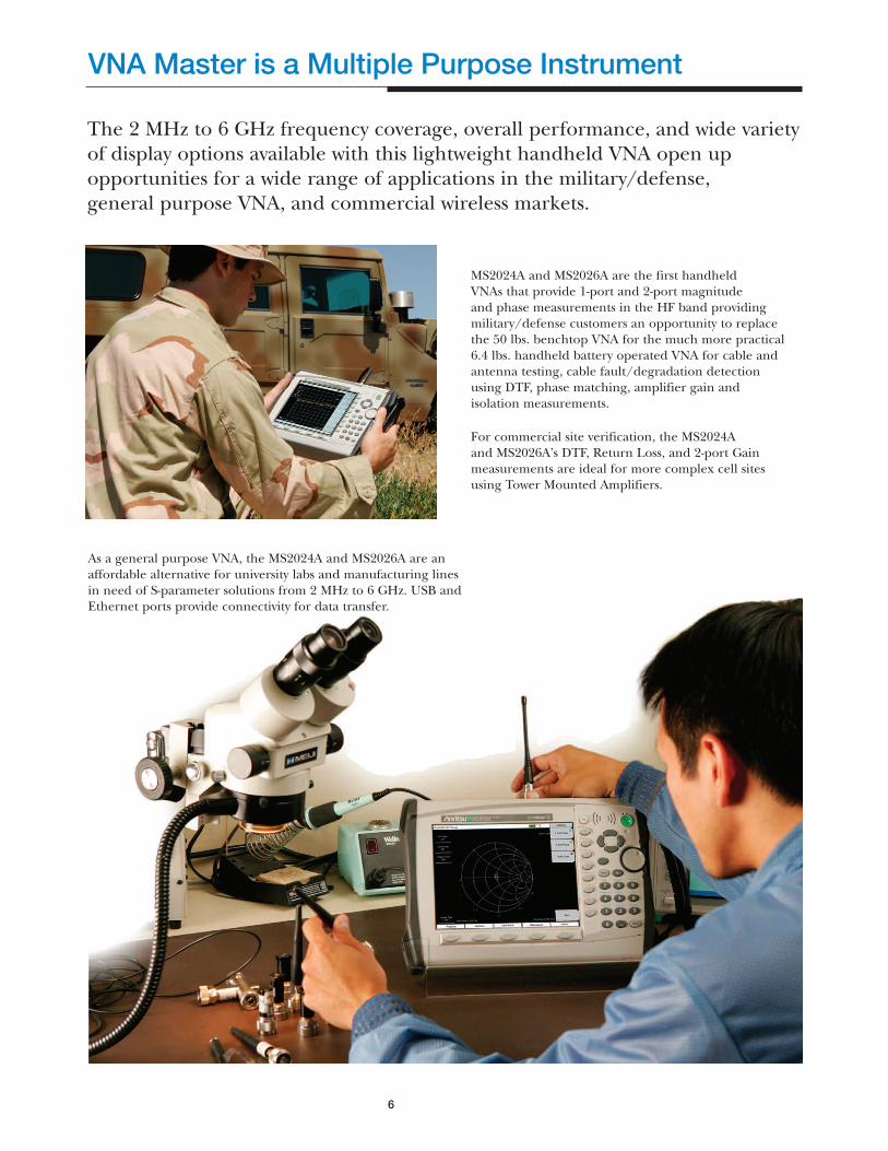
The 2 MHz to 6 GHz frequency coverage, overall performance, and wide varietyof display options available with this lightweight handheld VNA open upopportunities for a wide range of applications in the military/defense,general purpose VNA, and commercial wireless markets.
MS2024A and MS2026A are the first handheld VNAs that provide 1-port and 2-port magnitudeand phase measurements in the HF band providingmilitary/defense customers an opportunity to replacethe 50 lbs. benchtop VNA for the much more practical6.4 lbs. handheld battery operated VNA for cable andantenna testing, cable fault/degradation detectionusing DTF, phase matching, amplifier gain andisolation measurements.
For commercial site verification, the MS2024Aand MS2026A’s DTF, Return Loss, and 2-port Gainmeasurements are ideal for more complex cell sitesusing Tower Mounted Amplifiers.
As a general purpose VNA, the MS2024A and MS2026A are anaffordable alternative for university labs and manufacturing linesin need of S-parameter solutions from 2 MHz to 6 GHz. USB andEthernet ports provide connectivity for data transfer.

GPS Receiver (Option 31)Built-in GPS provides precise location (latitude, longitude, andaltitude) and Universal Time (UT) information to help the userverify that measurements are taken at the right location. The MS2024Aand MS2026A then stamp each trace and store the GPS locationinformation. This stored data can be used to stamp traces takenindoors at the same cell site location. The GPS option also comeswith a convenient magnet-mount antenna with a 15-foot (5m) cablefor the car, truck or any other useful surface.
7
Power Monitor (Option 5)With the Anritsu 560 and 5400 series detectors, technicians canaccurately measure broadband power up to 50 GHz. These high-precision detectors significantly help minimize mismatch uncertaintywith detector flatness better than 0.5 dB up to 18 GHz.
The Power Monitor also features:
n Measurement range (-50 to +16 dBm)
n Display range (-80 to +80 dBm)
n Display formats: absolute power (dBm or Watts) and relative power(dB or %).
n Built-in auto averaging automatically reduces noise effects whileZeroing allows optimum measurement accuracy at low power levels.
Extend the Functionality with Valuable Options
GPS Receiver
Bias Tee (Option 10)The integrated, variable Bias Tee isdesigned to supply bias to the TMAor other active devices, delivering avariable +12 to +24V in 3V steps to thecenter conductor of the RF In port.
TMA-DD
ANT RX
RF OUT RF IN
(Bias Tee)
TX
VNA Master

8
Robust and Dynamic Software for Added Proficiency
Master Software Tools
Master Software ToolsEvery MS2024A and MS2026A comes with Master Software Tools,a comprehensive data management and analysis software that provides asimple and easy method for managing, archiving, analyzing, printing andreporting system performance and trends. With Master Software Tools(Windows® 2000/XP compatible) the MS2024A and MS2026A can:
n Establish connection to a PC using Ethernet or USB
n Obtain VSWR, Cable Loss, DTF, Phase, or Smith Chart plots from oneReturn Loss measurement
n Add/Modify Limit Lines and Markers
n Simplify the task of comparing traces with intelligent drag and drop
n Handle long file names for easy, descriptive data labeling
n Display power level, calibration status, GPS information, and Bias Teeinformation along with a trace in one professional report
n Upload new cable and signal standards
n Upload traces into the unit for field comparison against historical data
n Store an unlimited number of traces to a PC to help analyze andmonitor historical performance
n Add custom languages using the Language Editor

9
Performance Detail
The uncertainty graphs above provide measurement uncertainty at 23°C after vector correction for the standard N connector type. Errors are worse-case contributionsof residual directivity, source match, frequency response, network analyzer dynamic range, and connector repeatability. For the 1-path 2-port measurements,transmission tracking, crosstalk and physical load match termination was added. OSLN50-1 calibration components were used.
0.025-0.3 GHz 0.3-3 GHz 3-6 GHz
Reflection Magnitude Uncertainty (S21=0)10
1
0.1-60 -50 -40 -30 -20 -10 0
lS11l (dB)
Est
imat
ed U
ncer
tain
ty (d
B)
0.025-0.3 GHz 0.3-3 GHz 3-6 GHz
Reflection Phase Uncertainty (S21=0)100
10
1-30 -25 -20 -15 -10 -5 0
lS11l (dB)
Est
imat
ed U
ncer
tain
ty (d
eg)
Transmission Magnitude Uncertainty (S11=0)10
1
0.1-60 -50 -40 -30 -20 -10 0
lS21l (dB)
Est
imat
ed U
ncer
tain
ty (d
B)
0.025-0.3 GHz 0.3-3 GHz 3-6 GHz
Power Monitor–DetectorsModel Frequency Range Impedance Return Loss Input Connector Frequency Response
5400–71N50 0.001 to 3 GHz 50Ω 26 dB N(m) ±0.2 dB, <1 GHz±0.3 dB, <3 GHz
5400–71N75 0.001 to 3 GHz 75Ω 26 dB, <2 GHz20 dB, <3 GHz
N(m) ±0.2 dB, <1 GHz±0.5 dB, <3 GHz
560–7A50 0.01 to 18 GHz 50Ω 15 dB, <0.04 GHz17 dB, <18 GHz22 dB, <8 GHz
GPC–7 ±0.5 dB, <18 GHz
560–7N50B 0.01 to 20 GHz 50Ω 15 dB, <0.04 GHz22 dB, <8 GHz17 dB, <18 GHz14 dB, <20 GHz
N(m) ±0.5 dB, <18 GHz±1.25 dB, <20 GHz
560–7S50B 0.01 to 20 GHz 50Ω 15 dB, <0.04 GHz22 dB, <8 GHz17 dB, <18 GHz14 dB, <20 GHz
WSMA(m) ±0.5 dB, <18 GHz±1.25 dB, <20 GHz
560–7S50–2 0.01 to 26.5 GHz 50Ω 15 dB, <0.04 GHz22 dB, <8 GHz17 dB, <18 GHz14 dB, <26.5 GHz
WSMA(m) ±0.5 dB, <18 GHz±1.25 dB, <26.5 GHz
560–7K50 0.01 to 40 GHz 50Ω 12 dB, <0.04 GHz22 dB, <8 GHz17 dB, <18 GHz15 dB, <26.5 GHz14 dB, <32 GHz13 dB, <40 GHz
K(m) ±0.5 dB, <18 GHz±1.25 dB, <26.5 GHz±2.2 dB, <32 GHz±2.5 dB, <40 GHz
560–7VA50 0.01 to 50 GHz 50Ω 12 dB, <0.04 GHz19 dB, <20 GHz15 dB, <40 GHz10 dB, <50 GHz
V(m) ±0.8 dB, <20 GHz±2.5 dB, <40 GHz±3.0 dB, <50 GHz
Uncertainty Curves

10
Specifications
VNA Master™ MS2024A and MS2026A are the most ultra-portable VNAs on themarket providing high performance 1-port and 1-path 2-port VNA measurementsfrom 2 MHz to 4 GHz (MS2024A) and 2 MHz to 6 GHz (MS2026A). VNA Master’slight weight (6.4 lbs.) and three hour battery life provide you with the flexibilityneeded to make VNA measurements anywhere.
FrequencyFrequency Range: 2 to 4000 MHz (MS2024A)
2 to 6000 MHz (MS2026A)Frequency Accuracy: 25 ppmFrequency Resolution1: 10 kHzData Points: Low, Medium, High (137/275/551)Interference Immunity2:On-Channel: +17 dBmOn-Frequency: +10 dBm (RF Out), +30 dBc RF In1-Port Power: High: 0 dBm (typical)2-Port Power: High: 0 dBm (typical)
Low: –35 dBm (typical)Residual Directivity3: 42 dB (2 MHz to 6 GHz)1-Port Accuracy3: = <0.8 + |20 log(1 ±10-E∆/20)| dB, typical
E∆ = Directivity – Measured Return LossSystem Dynamic Range: 80 dB, 2 MHz to 3 GHz
70 dB, >3 GHz to 5.5 GHz65 dB, >5.5 GHz to 6 GHz
Return Loss Range: 0 to 60 dBResolution: 0.01 dB
VSWR Range: 1 to 65Resolution: 0.01
Cable Loss Range: 0 to 30 dBResolution: 0.01 dB
1-Port Phase Range: –180° to +180°Resolution: 0.01°
Smith Chart Resolution: 0.01
2-Port Gain Range: –120 to 100 dBResolution: 0.01 dB
2-Port Phase Range: –180° to +180°Resolution: 0.01°
Dynamic Range 80 dB, 2 MHz to 3 GHz70 dB, 3 GHz to 5.5 GHz65 dB, 5.5 GHz to 6 GHz
Distance-to-Fault (DTF)Fault Resolution (meters): (1.5 x 10⁸ x vp)/∆F vp is the propagation
constant and ∆F is F2–F1 in HzHorizontal Range (meters): 0 to (data points–1) x Fault Resolution to
a maximum of 1500m (4921 ft.) wheredatapoints = 137/275/551
Vertical Range (Return Loss): 0 to 60 dBVertical Range (VSWR): 1 to 65
RF Power Monitor (Option 5)Display Range: –80 to +80 dBm (10 pW to 100 kW)Measurement Range: –50 to +16 dBm (10 nW to 40 mW)Offset Range: 0 to +60 dBResolution: 0.1 dB or 0.1 WAccuracy: ±1 dB
GPS Receiver (Option 31) GPS Location Indicator, Latitude,Longitude and Altitude, and UTC
Bias Tee (Option 10)Voltage/Current: +12V, 250 or 500 mA steady state
+15V, 250 or 500 mA steady state+18V, 350 mA steady state+21V, 300 mA steady state+24V, 250 mA steady state
General SpecificationsLanguages Built-in English, Spanish, Italian, French, German,Japanese, Korean, and Chinese. Can also customize two additionallanguages using Master Software Tools.
Memory Internal memory provides for the storage and recall of morethan 1000 traces and setups. The contents of the internal memory canbe copied to and from a removable Compact Flash card.
Markers six markers (delta marker, peak search, valley search) andMarker Table.
Traces View Trace, Memory, Trace – Memory, Trace + Memory, Traceand Memory
Limit Lines Upper and Lower Limit. Each upper and lower limit can bemade up of one to forty segments.
Display Bright daylight-viewable color TFT LCD, Full SVGA, 8.4 in.
Interface ConnectorsType N female RF Out Port and RF In Port (50Ω)5-pin Mini-B USB 2.0 for data transfer to a PCRJ45 Connector for Ethernet 10/100 Base-T2.5 mm 3-wire cellular headset connector
Remote Programmability Commands Not Available
Power Supply External DC Input, +12V, 5A max
ESD Damage Level 10 kV
Maximum Input (Damage Level) Test Port, Type N: +22 dBmRF Detector: +20 dBm
Impedance 50 Ω
Dimensions 12 x 8 x 3 in. (305 x 203 x 76 mm)
Weight <6.4 lbs (2.9 kg)
Environment MIL–PRF–2800F Class 2
Operating: –10°C to 55°C, humidity 85% or lessStorage: –51°C to 71°CAltitude: 4600 meters, operating and non-operating
Safety Conforms to EN 61010–1 for Class 1 portable equipment
Electromagnetic Compatibility Meets European Communityrequirements for CE marking.
1 If display resolution (Span/(DataPoints–1)) is less than 150 kHz, then frequency resolutiononly applies to measurements with RF Immunity set to Normal.
2 On Channel Interference Immunity is specified at >1.0 MHz of the carrier frequency.On-Frequency Interference Immunity is specified to within ±10 kHz of the carrier frequency.
3 All accuracy and directivity specifications apply only when using Anritsu precisioncomponents.
4 For data transfer only, remote programmability commands not available.

11
Ordering Information
Site Master Base ModelMS2024A 2-Port VNA Master 2 MHz to 4 GHzMS2026A 2-Port VNA Master 2 MHz to 6 GHz
OptionsMS2020/5 Power Monitor (requires external detector)
MS2020/10 Built-in Variable Bias Tee
MS2020/31 GPS (includes GPS antenna 2000–1410)
Standard Accessories (One year warranty)
10580–00122 User’s Guide61382 Soft Carrying Case2000-1358 Compact Flash Card (64 MB)64343 Tilt Bail2300–498 Master Software Tools CD ROM633–44 Rechargeable Li-Ion Battery40–168 AC-DC Adapter806–141 Automotive cigarette lighter 12 V DC Adapter2000–1360 USB A–to mini B cable, 6 feet (1.83m)2000–1371 Ethernet cable, 7 feet (2.13 m)
Optional AccessoriesOSLN50–1 Precision N(m) Open/Short/Load, 42 dB, 6 GHzOSLNF50–1 Precision N(f) Open/Short/Load, 42 dB, 6 GHz22N50 Precision N(m) Short/Open, 18 GHz22NF50 Precision N(f) Short/Open, 18 GHzSM/PL–1 Precision N(m) Load, 42 dB, 6.0 GHzSM/PLNF–1 Precision N(f) Load, 42 dB, 6.0 GHz2000–767 Precision Open/Short/Load, 7/16(m), 4.0 GHz2000–768 Precision Open/Short/Load, 7/16(f), 4.0 GHz1N50C Limiter, N(m) to N(f), 50Ω, 0.01 to 50 GHz42N50–20 Attenuator, 20 dB, 5W, DC to 18 GHz, N(m)–N(f)42N50A–30 Attenuator, 30 dB, 50W, DC to 18 GHz, N(m)–N(f)2000–1410 Magnet Mount GPS Antenna with 15 ft (4.6m) cable760–235 Hard Transit Case10580–00122 User’s Guide61382 Soft Carrying Case2000-1358 Compact Flash Card (64 MB)2000-1374 Dual Battery Charger64343 Tilt Bail2300–498 Master Software Tools CD ROM633–44 Rechargeable Li-Ion Battery40–168 AC-DC Adapter806–62 Automotive cigarette lighter 12 VDC Adapter2000–1360 USB A to mini B cable, 6 feet (1.83m)2000–1371 Ethernet cable, 7 feet (2.13 m)
Precision Adaptors34NN50A N(m)–N(m), DC to 18 GHz, 50Ω34NFNF50 N(f)–N(f), DC to 18 GHz, 50Ω
Adaptors1091–26 N(m)–SMA(m), DC to 18 GHz, 50Ω1091–27 N(m)–SMA(m), DC to 18 GHz, 50Ω1091–80 N(f)–SMA(m), DC to 18 GHz, 50Ω1091–81 N(f)–SMA(f), DC to 18 GHz, 50Ω1091–172 N(m)–BNC(f), DC to 1.3 GHz, 50Ω510–90 7/16 DIN(f)–N(m), DC to 7.5 GHz, 50Ω510–91 7/16 DIN(f)–N(f), DC to 7.5 GHz, 50Ω
510–92 7/16 DIN(m)–N(m), DC to 7.5 GHz, 50Ω510–93 7/16 DIN(m)–N(f), DC to 7.5 GHz, 50Ω510–96 7/16 DIN(m)–N(m), DC to 7.5 GHz, 50Ω510–97 7/16 DIN(f)–N(f), DC to 7.5 GHz, 50Ω510–102 N(m)–N(m), 90° right angle, DC to 11 GHz, 50Ω
Detector Extender Cable800–109 7.6m (25 ft.)800–110 15.2m (50 ft.)800–111 30.5m (100 ft.)800–112 61.0m (200 ft.)
Band Pass Filter 1030–109 836.5 MHz Ctr Freq, 25.8 MHz BW, N(m) to SMA(f), 50Ω1030–110 897.5 MHz Ctr Freq, 35 MHz BW, N(m) to SMA(f), 50Ω1030–111 1.88 GHz Ctr Freq, 63.1 MHz BW, N(m) to SMA(f), 50Ω1030–112 2.442 GHz Ctr Freq, 85.1 MHz BW, N(m) to SMA(f), 50Ω
Test Port Cable Armored15NN50A 1.5 meters, N(m)–N(m), 6 GHz, 50Ω15NN50–3.0C 3.0 meters, N(m)–N(m), 6 GHz, 50Ω15NN50–5.0C 5.0 meters, N(m)–N(m), 6 GHz, 50Ω15NN50–1.5C 1.5 meters, N(m)–N(f), 6 GHz, 50Ω15NN50–3.0C 3.0 meters, N(m)–N(f), 6 GHz, 50Ω15NN50–5.0C 5.0 meters, N(m)–N(m), 6 GHz, 50Ω15ND50–1.5C 1.5 meters, N(m)–7/16 DIN(m), 6 GHz, 50Ω15NDF50–1.5C 1.5 meters, N(m)–7/16 DIN(f), 6 GHz, 50Ω
Literature10580–00122 MS2024A/MS2026A User’s Guide10580–00123 MS2024A/MS2026A Programming Manual11410–00369 MS2024A/2026A Brochure11410-00372 MS2024A/MS2026A Technical Datasheet11410–00274 Tower Mounted Amplifiers Application Note11410–00214 Reflection Measurement Application Note

Discover What’s Possible®©Anritsu October 2005. All trademarks are registered trademarks of their respective companies. Data subject to change without notice. For most recent specifications visit www.us.anritsu.com.
PN: 11410-00369, Rev. A
SALES CENTERS:United States (800) ANRITSU Europe 44 (0) 1582-433433 Microwave Measurement Division Canada (800) ANRITSU Japan 81 (46) 223-1111 490 Jarvis Drive, Morgan Hill, CA 95037-2809South America 55 (21) 2527-6922 Asia-Pacific (852) 2301-4980 http://www.us.anritsu.com