VMworld 2016: How to Deploy VMware NSX with Cisco Infrastructure
47
How to Deploy VMware NSX with Cisco Infrastructure Ron Fuller, VMware Paul Mancuso, VMware NET8364R #NET8364R
-
Upload
vmworld -
Category
Technology
-
view
768 -
download
9
Transcript of VMworld 2016: How to Deploy VMware NSX with Cisco Infrastructure

How to Deploy VMware NSX with Cisco InfrastructureRon Fuller, VMwarePaul Mancuso, VMware
NET8364R
#NET8364R

Growing NSX MomentumA rapid journey of customer adoption across industries
1700+ Customers
8 out of VMware’s top 10 deals in Q216included NSX
100% YoY growthConsistent year-to-year Q216Q215Q214Q213

SecurityInherently secure infrastructure
Automation IT at the speed of business
Application continuityData center anywhere
NSX customer use cases
Micro-segmentation
DMZ anywhere
Secure end user
IT automating IT
Multi-tenant infrastructure
Developer cloud
Disaster recovery
Cross cloud
Multi data center pooling

• This presentation may contain product features that are currently under development.
• This overview of new technology represents no commitment from VMware to deliver these features in any generally available product.
• Features are subject to change, and must not be included in contracts, purchase orders, or sales agreements of any kind.
• Technical feasibility and market demand will affect final delivery.
• Pricing and packaging for any new technologies or features discussed or presented have not been determined.
Disclaimer
CONFIDENTIAL 4

CONFIDENTIAL 5
Session AbstractMany enterprises rely on both VMware vSphere and Cisco Nexus/UCS to build the foundation of their data center infrastructure. While VMware NSX brings advanced network automation and security capabilities to vSphere on any network infrastructure, this session will cover the NSX design considerations specific to environments using Cisco Nexus switches for the physical network, and Cisco UCS for the vSphere compute resources. This session will also show how to run NSX while utilizing the underlay functionality of Cisco ACI. The session will provide a review of the most important topics from the two VMware NSX + Cisco Nexus/ACI design guides already published, while adding additional “lessons learned” from real deployments in the field since those publications.

CONFIDENTIAL 6
Session Goals• Session is a complement to the NSX & Cisco Design Guide available here and the
Deploying NSX with Cisco ACI design guide available here
• Understand how to implement a Nexus and ACI based design with NSX
• Covers both Cisco Nexus 9K in NX-OS mode and ACI mode

CONFIDENTIAL 7
Ron Fuller• Staff Systems Engineer – NSBU
• Cisco Certified Internetwork Expert (CCIE) #5851 Emeritus (R&S/Storage)
• More than 20 years of networking experience
• 9 Years at Cisco – SE/CSE/Data Center TSA/TME
• CiscoPress Published Author
• VMwarePress Published Author

CONFIDENTIAL 8
Paul MancusoTechnical Product Manager – NSBU
• VCDX#159
• VCIX-NV
• VCI
• CCSI
• CCNP; CCNP Data Center
• MCSE
• CISSP
• 25 years of networking experience
• Author of 5 books
• Author of over 3 dozen courses on Cisco and Microsoft
CONFIDENTIAL
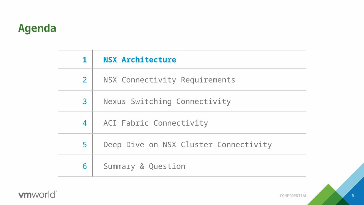
Agenda
9
1 NSX Architecture
2 NSX Connectivity Requirements
3 Nexus Switching Connectivity
4 ACI Fabric Connectivity
5 Deep Dive on NSX Cluster Connectivity
6 Summary & Question

CONFIDENTIAL 11
ProvidesA Faithful Reproduction of Network & Security Services in Software
Management APIs, UI
LoadBalancingPolicies,
Groups, Tags
Activity Monitoring
Switching ECMP Connectivity to Physical Networks
DLR
Reference Architecture NET7857R & NET7858R
VPN ServicesFirewall

CONFIDENTIAL 12
Cloud Consumption
Data Plane
ESXi Hypervisor Kernel Modules
Distributed Services
• High – Performance Data Plane• Scale-out Distributed Forwarding Model
Management PlaneNSX Manager
• Single configuration portal• REST API entry-point
Control PlaneNSX Controller • Manages Logical networks
• Control-Plane Protocol• Separation of Control and Data Plane
…
…
FirewallDistributed Logical Router
LogicalSwitch
Edge
• Self Service Portal• vRealize Automation, OpenStack, Custom
NSX Logical Router Control VM
NSX Architecture and Components
Agenda
CONFIDENTIAL 13
1 NSX Architecture
2 NSX Connectivity Requirements
3 Nexus Switching Connectivity
4 ACI Fabric Connectivity
5 Deep Dive on NSX Cluster Connectivity
6 Summary & Question

CONFIDENTIAL 14
Compute Cluster ConsolidatedInfrastructure & Mgmt.
Cluster
Nexus Leaf
Edge Leaf
DC CoreInternet/DMZ
Nexus Spine
L3
L2
L3
L2
Edge ClusterUCS C-Series
95xx 95xx 95xx95xx
93xx 93xx 93xx 93xx 93xx 93xx 93xx 93xx
NSX Connectivity with Cisco UCS and Nexus Switches

CONFIDENTIAL 15
vSphere Host (ESXi)
Layer 2 or Layer 3 Uplinksbased on topology
VLAN Trunk (802.1Q)
VLAN 66
Mgmt
10.66.1.2/26DGW: 10.66.1.1
VLAN 77
vMotion
10.77.1.2/26DGW: 10.77.1.1
VLAN 88
VXLAN
10.88.1.2/26DGW: 10.88.1.1
VLAN 99
Storage
10.99.1.2/26DGW: 10.99.1.1
SVI 66: 10.66.1.1/26SVI 77: 10.77.1.1/26SVI 88: 10.88.1.1/26SVI 99: 10.99.1.1/26
Spa
n of
VLA
Ns
Spa
n of
VLA
Ns
VMkernel Networking – L2 OR L3 Topology

CONFIDENTIAL 16
VLANs Requirements for NSX• At minimum 4 VLANs for compute
• Minimum two additional VLANs for N-S traffic for edge hosts only
• P-V bridging VLANs as needed
• VLAN ID for VXLAN needs to be consistent across transport zone
• The dedicated TCP/IP stack for VXLAN and vMotion – “Default” used for everything else
• Starting with vSphere 6.0, routed vmkernel network for vMotion no longer requires RPQ
Traffic Type Function VLAN ID
Management ESXi and NSX Management 100
vMotion VM Mobility 101
IP Storage VLAN
Application and infrastructure DS
connectivity102
VXLAN Guest VM Traffic 103
N-S Traffic Route Peering 105/106
BridgingOptional
Migration and non IP traffic 107
Com
pute
Clu
ster
Edge
Clu
ster
VLAN values shown are for example use

CONFIDENTIAL 17
NSX VXLAN Capability – No Multicast Required• Standard VXLAN requires multicast on
physical network– L2 network – relatively easy IGMP
Snooping & Querier– L3 network – additionally requires PIM
• NSX offers a choice in which multicast configuration is not required
• L2 frame is encapsulated at the hypervisor – reducing complex configuration on physical network
• VTEP (VXLAN Tunnel EndPoint) is a logical interface (VMkernel) connects to TZ for encap/decap VXLAN traffic
VM Sends a standard L2
Frame
Source Hypervisor (VTEP)encapsulates VXLAN, UDP
& IP Headers
Destination Hypervisor (VTEP) decapsulate
headers
Physical Network forwards frame as standard IP frame
Original L2 Frame delivered to VM
VXLANVTEP
VXLANVTEP
IP FrameL2 Frame L2 Frame
1
2 43 5
L2 IP UDP VXLAN PayloadL2
1
2
3
4
3
UDP VXLAN PayloadL2
5
Nexus 93XXNX-OS Mode
Nexus 93XXNX-OS Mode

CONFIDENTIAL 18
Transport Zone, VTEP, Logical Networks and VDS• Transport Zone: Collection of VXLAN prepared
ESXi clusters• VTEP is a VMkernel interface created dynamically
during the cluster VXLAN preparation– Belongs to a specific VLAN backed port-group– vDS uplink configuration requires consistency
for the vDS– VLAN ID for the VXLAN Transport must be
the same
• Only 1 vDS per ESXi cluster can be enabled for VXLAN• Logical Switch is represented as a dvPortgroup may
span multiple vDS• vDS is licensed with NSX on any vSphere version
– Enterprise+ is required for Non-NSX use of vSphere hosts
• vDS is the ONLY vSwitch that supports NSX– MUST be managed by vSphere
• N1Kv is not supported but may co-exist for non-NSX cluster usage
vSphere Host
VXLAN Transport Network
10.20.10.10
Host 1
10.20.10.11VTEP1 VTEP2
VM
VXLAN 5002 MAC2
vSphere Host10.20.10.12
Host 2
10.20.10.13
VM
MAC4
VM
MAC1
VM
MAC3
VTEP3 VTEP4
Compute VDS Edge VDS

CONFIDENTIAL 19
VDS Uplink Design• NSX create dvUplink port-groups for VXLAN
enabled hosts. This uplink connectivity carrying VXLAN traffic.
• Must be consistent for all hosts belonging to the VDS• Must carry same teaming policy
– For the VXLAN traffic, the choice in teaming mode depends on• Simplicity• Bandwidth requirement
– Recommended teaming mode with standard rack servers • Dependent upon functional goals as listed in table
– Recommended teaming mode with UCS Blade System is “route Based on Originating Port”• LACP is not possible from UCS blade
– Having multiple VDS for compute and Edge allow flexibility of teaming mode for uplink configuration
Teaming and Failover Mode
NSX Supp
ort
Multi-VTEP
Support
Uplink Behavior2 x 10G
Nexus Port Configuration
Route based on Originating Port ✓ ✓ Both Active Standard
Route based on Source MAC
hash✓ ✓ Both Active Standard
LACP ✓ × Flow based –both active
vPC Port-Channel - LACP
Route based on IP Hash (Static EtherChannnel)
✓ ×Flow based –both active
vPC Port-Channel – LACP mode OFF
Explicit Failover Order ✓ × Only one link is
activeStandard
Route based on Physical NIC Load (LBT)
× × × Standard

CONFIDENTIAL
Agenda
20
1 NSX Architecture
2 NSX Connectivity Requirements
3 Nexus Switching Connectivity
4 ACI Fabric Connectivity
5 Deep Dive on NSX Cluster Connectivity
6 Summary & Question

CONFIDENTIAL
NSX is AGNOSTIC to Underlay Network TopologyL2 or L3 or Any Combination
Regardless of switched infrastructure
Only Two Requirements
2) IP Connectivity 1) MTU of 1600
NSX Switching Overview and Requirements
21

CONFIDENTIAL 22
Jumbo MTU Considerations• VXLAN encap traffic is >= 1600 UDP frame
• VDS Max MTU is 9000 Byte
• Nexus 7xxx, 9xxx Series– L2 only requires global configuration– L3 requires per interface MTU change
• Nexus 5xxx, 56xx and 6xxx requires– MTU to be changed with Policy-Map– L3 requires per interface MTU change
• All links belonging to fabric must be enabled with Jumbo MTU
Layer 2 Interface Layer 3 Interface
system jumbomtu 9216 Global configurationsinterface Ethernet1/9 description to esx-vmnic3-VMK switchport mode trunk switchport trunk allowed vlan 22-25 spanning-tree port type edge trunk mtu 9216 Layer 2 MTU channel-group 9 mode active
interface Vlan151 SVI Interface no ip redirects ip address 10.114.221.34/27 hsrp 1 ip 10.114.221.33 description VXLAN Transport Zone no shutdown mtu 9216 interface Ethernet2/12 Layer 3 Interface description L3 Link to Spine no switchport speed 40000 duplex full mtu 9216 ip address 10.114.211.117/31 no shutdown
Nexus 7000 / 9000 series

CONFIDENTIAL
• VXLAN encap traffic is >= 1600 UDP frame
• VDS Max MTU is 9000 Byte
• Nexus 7xxx, 9xxx Series
– L2 only requires global configuration
– L3 requires per interface MTU change
• Nexus 5xxx, 56xx and 6xxx requires
– MTU to be changed with Policy-Map
– L3 requires per interface MTU change
• All links belonging to fabric must be enabled with Jumbo MTU
23
All L2 interfaces Layer 3 Interface
Only global configurations
Create policy-map:
policy-map type network-qos jumbo class type network-qos class-default mtu 9216
Apply policy-map:
system qos service-policy type network-qos jumbo
interface Vlan151 SVI Interface no ip redirects ip address 10.114.221.34/27 hsrp 1 ip 10.114.221.33 description VXLAN Transport Zone no shutdown mtu 9216 interface Ethernet2/12 Layer 3 Interface description L3 Link to Spine no switchport speed 40000 duplex full mtu 9216 ip address 10.114.211.117/31 no shutdown
Nexus 5xxx and 6xxx series
Jumbo MTU Considerations

CONFIDENTIAL 24
VLANs & IP Subnet Defined at each ToR
SVI Interface VLAN ID IP Subnet
Management 100 10.100.R_ID.x/24
vMotion 101 10.101.R_ID.x/24
Storage 102 10.102.R_ID.x/24
VXLAN 103 10.103.R_ID.x/24
VLANs & IP Subnet Defined at 95xx for POD A
SVI Interface VLAN ID IP Subnet
Management 100 10.100.A.x/24
vMotion 101 10.101.A.x/24
Storage 102 10.102.A.x/24
VXLAN 103 10.103.A.x/24
VLANs & IP Subnet Defined at 95xx for POD B
SVI Interface VLAN ID IP Subnet
Management 200 10.200.B.x/24
vMotion 201 10.201.B.x/24
Storage 202 10.202.B.x/24
VXLAN 103 10.103.B.x/24
VXLAN VLAN ID 103 - Transport Zone Scope (extends across ALL PODs/clusters)
Compute Cluster A
Compute Cluster B
VLAN ID 100, 101 & 102 Scope VLAN ID 200, 201 and 203 Scope
POD A
L3
L2
UCS B-Series
95xx95xx
93xx 93xx 93xx 93xx
95xx 95xx
93xx93xx93xx93xx
POD B
UCS B-Series
L3 Core
L3
L2
Compute Cluster A
Compute Cluster B
VLAN ID 100, 101 & 102 Scope VLAN ID 200, 201 and 203 Scope
L3
L2
UCS B-Series
95xx95xx
93xx 93xx 93xx 93xx
95xx 95xx
93xx93xx93xx93xx
UCS B-Series
L3 Core
Rack 1 Rack N Rack 1 Rack N
VXLAN VLAN ID 103 - Transport Zone Scope (extends across ALL PODs/clusters)
POD A POD B
L3
L2
95xx95xx 95xx95xx
Cisco DC Topologies – Pod design – NSX is Agnostic
CONFIDENTIAL
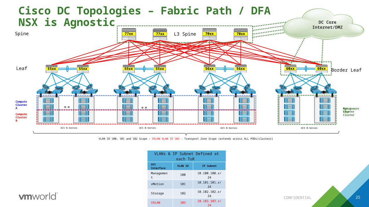
Cisco DC Topologies – Fabric Path / DFANSX is Agnostic
25
VLAN ID 100, 101 and 102 Scope – VXLAN VLAN ID 103 - Transport Zone Scope (extends across ALL PODs/clusters)
Compute Cluster A
Compute Cluster B
77xx 77xx
UCS B-Series
55xx55xx 55xx 55xx
UCS B-Series
56xx 56xx 60xx 60xx
70xx 70xxSpine
Leaf
UCS B-Series UCS B-Series
Border Leaf
Mgt / Edge Cluster
VLANs & IP Subnet Defined at each ToR
SVI Interface VLAN ID IP Subnet
Management 100 10.100.100.x/24
vMotion 101 10.101.101.x/24
Storage 102 10.102.102.x/24
VXLAN 103 10.103.103.x/24
L3 Spine
ManagementCluster
DC CoreInternet/DMZ

CONFIDENTIAL
Cisco DC Topologies – ACINSX is Agnostic
26
VLAN ID 100, 101 and 102 Scope – VXLAN VLAN ID 103 - Transport Zone Scope (extends across ALL PODs/clusters)
Compute Cluster A
Compute Cluster B
UCS B-Series UCS B-Series
Spine
Leaf
UCS B-Series UCS B-Series
Border Leaf
Mgt / Edge Cluster
VLANs & IP Subnet Defined at each ToR
SVI Interface VLAN ID IP Subnet
Management 100 10.100.100.x/24
vMotion 101 10.101.101.x/24
Storage 102 10.102.102.x/24
VXLAN 103 10.103.103.x/24
DC CoreInternet/DMZ

CONFIDENTIAL 27
NSX Component Mapping• Separation of compute, management and Edge
function with following design advantage
• Management Cluster– Can co-exist with Edge Cluster in same
UCS Chassis– Minimum three hosts – more if needed– LACP can be used on rack-mount
• Edge Cluster– Should be independent UCS C series– Edge VM for North-south traffic – Active-standby Control-VM– Can hold NSX Controller is optimization of
resources is desired
• Compute Cluster– VXLAN is enabled per cluster– Can co-exist with physical bare-metal compute
Function NSX Components Recommended Cluster Designation
Management Plane NSX Manager & VC Management Cluster
Control PlaneNSX Controller Cluster Management or
Edge Cluster
Logical Router Control VM Edge Cluster
Data Plane East-West
VXLAN forwarding - compute and edge
VDS kernel components &
DLR(Distributed Logical Routers)
Compute and Edge Cluster
Data PlaneNorth-South
ECMP Edge or Edge Services Edge Cluster
Bridging Traffic DLR Control VM Edge Cluster

CONFIDENTIAL
Agenda
28
1 NSX Architecture
2 NSX Connectivity Requirements
3 Nexus Switching Connectivity
4 ACI Fabric Connectivity
5 Deep Dive on NSX Cluster Connectivity
6 Summary & Question

CONFIDENTIAL 29
NSX + Cisco ACI for the physical network underlay functions• ACI EPG’s will map to VLANs• NSX to create overlay network and provide
all network virtualization functions
Customer Benefits• Customer can use APIC to program all
switches and perform tasks like config, upgrades, etc. from APIC
• Leverage fabric for enforcing infrastructure traffic isolation via EPG
• Full SDDC capabilities are available
Customer Proof Points• Some deployments of ACI and NSX
NSX provides the VXLAN overlay networksACI EPG maps to a VLAN to enforce the overlay
NSX with Cisco Underlay in ACI Mode

CONFIDENTIAL 30
NSX Using Cisco Nexus Switches as Underlay
• Full NSX Stack over ACI to leverage– Core network use case– Security
• Cisco ACI Specific Design Highlights– L2 fabric underlay with min 1600 MTU– EPG = BD = VLAN– 4 EPGs for fabric (compute and edge)– 2 EPG for Edge ECMP connectivity– NSX Edge maps to border leaf– BGP to ACI Border Leaf, active-active design
• Design Guide: Deploying NSX on ACI Underlay– https://communities.vmware.com/docs/DOC-30849
Recommended Design

CONFIDENTIAL 32
Web DB
DLR
E1
Border Leaf
App
ECMPE8
EPG/VLAN 20
Transit VXLAN
Active Standby
Routing Adjacency
…
EPG/VLAN 10
L3
L2
DC Core
ACI Spine
Edge Cluster
Host 1
Host 2
Host 3
L3
L2ACI Border
Leaf
Host 4
DC Core ACI Spine
NSX Edge Mapping to ACI Border Leaf

CONFIDENTIAL 33
Active-active DeploymentApplication active on both sides
VIP-active
APPA
APPB
APPC
GSLB
VIP-active
APPA
APPB
APPE
vCenter-A vCenter-B
Active-active application pair
Active-activeapplication pair

CONFIDENTIAL 34
Site A
Host 1
Host 2
Host 3
L3
L2ACI Border
Leaf
Host 4
DC Core ACI Spine
Site B
Host 1
Host 2
Host 3
L3
L2
Non ACI Network
Host 4
Even with Multi-DC:• NSX is always agnostic to the
underlay • Zero requirement for identical
hardware infrastructure at each site
• Use non-proprietary L3 connectivity between sites
• Still require the same few underlay features
• Jumbo MTU• Stabile L2/L3 IP
infrastructure
Multi-DC Heterogeneous DR

CONFIDENTIAL
Agenda
35
1 NSX Architecture
2 NSX Connectivity Requirements
3 Nexus Switching Connectivity
4 ACI Fabric Connectivity
5 Deep Dive on NSX Cluster Connectivity
6 Summary & Question
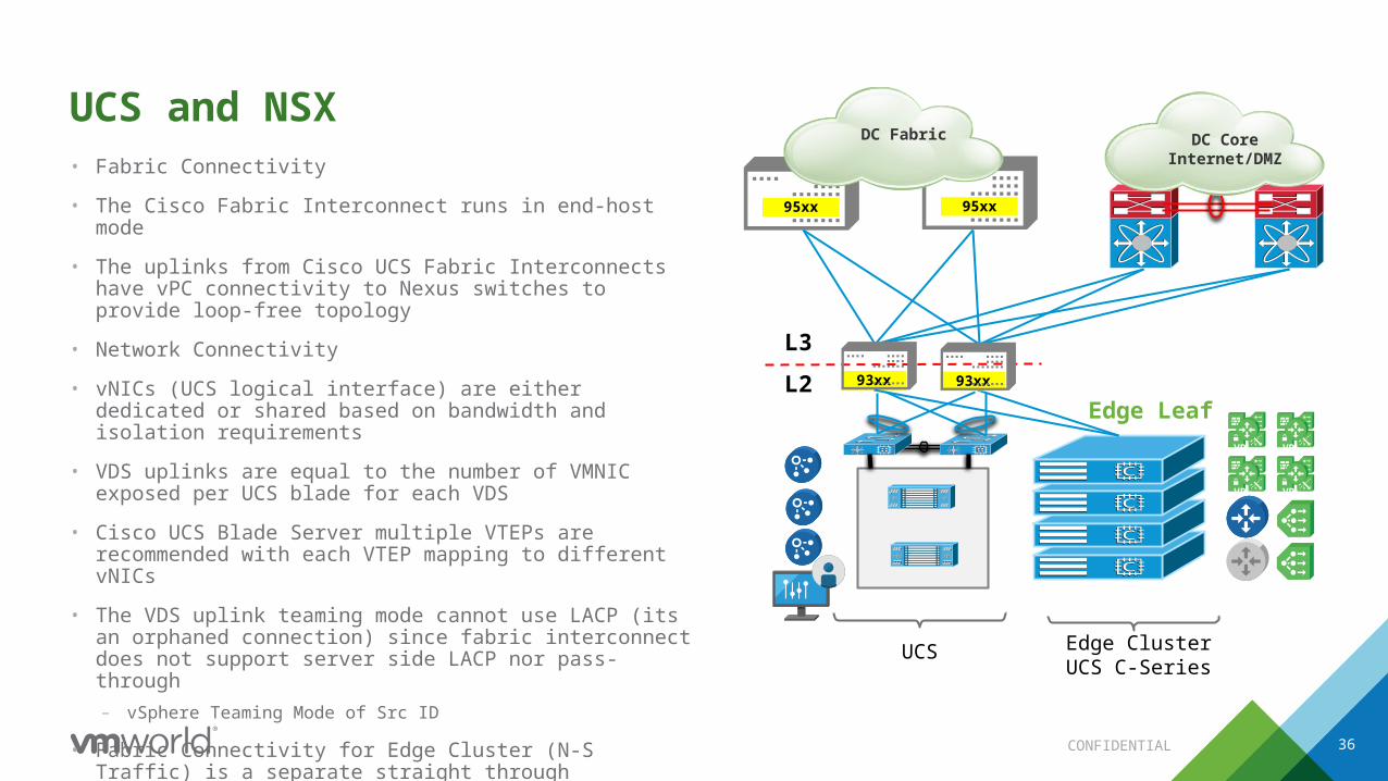
CONFIDENTIAL 36
95xx
UCS and NSX • Fabric Connectivity
• The Cisco Fabric Interconnect runs in end-host mode
• The uplinks from Cisco UCS Fabric Interconnects have vPC connectivity to Nexus switches to provide loop-free topology
• Network Connectivity
• vNICs (UCS logical interface) are either dedicated or shared based on bandwidth and isolation requirements
• VDS uplinks are equal to the number of VMNIC exposed per UCS blade for each VDS
• Cisco UCS Blade Server multiple VTEPs are recommended with each VTEP mapping to different vNICs
• The VDS uplink teaming mode cannot use LACP (its an orphaned connection) since fabric interconnect does not support server side LACP nor pass-through– vSphere Teaming Mode of Src ID
• Fabric Connectivity for Edge Cluster (N-S Traffic) is a separate straight through connection UCS
Edge Leaf
L3
L2
95xx
93xx
Edge ClusterUCS C-Series
DC CoreInternet/DMZ
DC Fabric
93xx
VPN
VPN
VPN
VPN

CONFIDENTIAL 37
VXLAN dvPortgroup (VTEP)
UCS Network Adapter & VXLAN• Assumes single UCS adaptor *
• Two VTEPs per blade is recommended – VXLAN VDS is exposed with two uplinks vNICs– Improves VXLAN throughput – Each VTEP is mapped to unique vNIC which then
maps to fabric A and B
• VXLAN traffic can be shared with other traffic on single VDS
• On UCS B-Series, recommend a dedicated VDS for the non-VPC transit VLAN used for routing N-S traffic
• * If more then one UCS network adaptor employed, recommendation is to expose two uplinks for the VDS that carries VXLAN traffic which will utilize two VTEPs when using vSphere Src ID Teaming
VMNIC 0 VMNIC 1
UCS B-Series Blade
vNIC 1
Teaming Mode
VMkernelVXLAN VTEP – 1
Traffic Type
SRC_ID
vNIC 0
dvUplink
VMkernelVXLAN VTEP – 2
SRC_ID
VDS - 1 MGMT, vMotion, NFS, VXLAN & Bridging

Routing Adjacency Uplink Teaming
Mode Non-VPC
VXLAN 5020Transit Link
VXLAN 5020Transit Link
Routing Adjacency
vSphere Host vSphere Host
Uplink TeamingMode VPC
Peering over VPCNot Supported on Cisco Nexus
Few exceptionNexus 7K with Release 7.2
Nexus 3K – BGP
Peering over non-VPCNon-LACP Teaming
UCS C Series
Peering over non-VPCParallel LinksUCS FI vPC
L3
L2
L3
L2
vPC and Routing Peer Termination

CONFIDENTIAL 39
NSX Edge Routing Design with UCS C Series & Intel NICs• 1:1 mapping is created between Edge uplinks
(VLAN backed networks) and routing neighbors on the ToR A/B– Map each of these VLANs (portgroups) to a different
dvUplink on Edge VDS to ensures distribution of N/S traffic across dvUplinks
– The VLANs used for dynamic routing are local to each router
– Edge Uplink = Host Uplink = VLAN = Adjacency– Avoid using VPC to ToR for route peering due to
vendor dependencies– Teaming mode is “route Based on Originating Port”
• Redundancy is handled by Dynamic Routing as Edges have adjacencies with both routers
• eBGP is used between NSX ESG and routers A/B
• Equally applicable to OSPF
• Default route must follow the uplink status NSX Edge Gateway (all ESGs use same uplink configuration)
VLAN 10 SVI(9K-A Only)
VLAN 20 SVI(9K-B Only)
Uplink A VLAN 10
vNIC1 Uplink A
Uplink B VLAN20
vNIC2 Uplink B
Edge Uplink Int 1 from VLAN 10 dvPortgroup
(vmnicX activevmnicY unused)
Edge Uplink Int 1 from VLAN 10 dvPortgroup
(vmnicX activevmnicY unused)
eBGP Peering
Default route advertised
downstream to 9K ToRs. Loss of both
uplinks should withdraw all routes
9K-B9K-A
95xx 95xx
VDS-Edge

CONFIDENTIAL 40
NSX Edge Routing Design with UCS B Series• Dedicated non-VPC links from FI to ToR
(pinned) VLANs used for Edge peering with N9Ks
• Port-Channel is used to maintain redundancy and scaling BW based on number of Edge VMs deployed
• 1:1 mapping between Edge uplinks (VLAN backed networks) and BGP neighbors on N9Ks.
• Redundancy with Dynamic Routing as Edges have adjacencies with both N9Ks
• Dedicated vNICs are created in UCS so that traffic for these VLANs is pinned to the FI uplinks
• eBGP is used between NSX ESG and N9Ks
• Default route must follow the uplink status
VLAN 10 SVI(9K-A Only)
VLAN 20 SVI(9K-B Only)
Dedicated non-vPC pinned for
VLAN 10
1 vNIC maps to Fabric A
Edge Uplink Int 1 from VLAN 10
dvPortgroup (vmnicX active
vmnicY unused)
Dedicated non-vPC pinned for
VLAN 20
1 vNIC maps to Fabric B
Default route advertised
downstream to 9K ToRs. Loss of both
uplinks should withdraw all routes
UCSFI-A
UCSFI-B
NSX Edge Gateway (all ESGs use same uplink configuration)
eBGP Peering Edge Uplink Int 2
from VLAN 20 dvPortgroup
(vmnicX activevmnicY unused)
95xx 95xx
9K-A 9K-B
VDS-Edge

CONFIDENTIAL 41
VMNIC 0 VMNIC 1 VMNIC 2 VMNIC 3
UCS B-Series Blade
vNIC 3vNIC 1
2204 FEX2204 FEX
6248 (A) 6248 (B)
Teaming Mode
VMkernelVXLAN
VTEP – 1
Traffic Type
VMkernelVXLAN
VTEP - 2
VMkernel vMotion
VMkernel Mgmt
VMkernel IP
Storage
LBT SRC_ID SRC_ID Explicit FailoverLBT
Nexus 93XXNX-OS Mode
Nexus 93XXNX-OS Mode
vNIC 4vNIC 2
VDS – 2 Routing
Routing VLAN PG 2
BridgingPG
dvUplink
Routing VLAN PG 1
VXLANdvPg
VDS - 1 MGMT, vMotion, NFS, VXLAN & Bridging
VDS Design, Uplink & Traffic Mapping• Recommend a minimum of two vDS for Edge Cluster
• VDS 1 – All traffic except N-S routing
• VDS 2 – N-S Traffic Routing VLANs – External Connectivity requires
dedicated non-VPC Links– Recommend a VDS for routing
VLAN pinned on dedicated straight through links
– Dual VTEP – each VTEP active on Fabric A and B respectively
– The teaming recommendation for VTEP is SRC_ID
– For the rest of the traffic teaming is based on local requirements
– For UCS C-series Edge cluster, a single VDS would suffice
CONFIDENTIAL
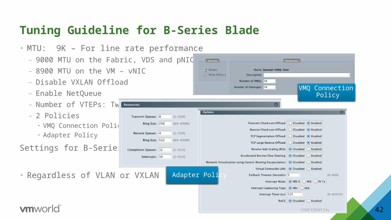
• MTU: 9K – For line rate performance– 9000 MTU on the Fabric, VDS and pNIC– 8900 MTU on the VM – vNIC– Disable VXLAN Offload – Enable NetQueue– Number of VTEPs: Two– 2 Policies
• VMQ Connection Policy• Adapter Policy
Settings for B-Series
• Regardless of VLAN or VXLAN
Tuning Guideline for B-Series Blade
42
Adapter Policy
VMQ Connection Policy

CONFIDENTIAL 43
NSX Design Guides• Reference Design: Deploying NSX with Cisco UCS
and Nexus 9000 Infrastructurehttps://communities.vmware.com/docs/DOC-29373
• Design Guide for Vmware NSX running with a Cisco ACI Underlay Fabrichttps://communities.vmware.com/docs/DOC-30849
• VMware® NSX for vSphere Network Virtualization Design Guide version 3.0https://communities.vmware.com/docs/DOC-27683
• More design documents https://www.vmware.com/support/pubs/vmware-validated-design-pubs.html
CONFIDENTIAL
Related VMworld Sessions• Introduction to Vmware NSX [NET7834]• Vmware NSX Deep Dive [9152]• Practical Path to NSX [8675]• NSX on ACI Customer Panel [8729]
• Explore NSX Feature Labs– Vmware NSX Feature Tour [SPL-1703-SDC-1]
• Self Paced Labs– Vmware NSX Feature Tour [ELW-1703-SDC-1]
• Expert Led Workshop
44

NSX partner ecosystem
Physical Infrastructure
Security
Application Delivery
Operations and Visibility
DYNAMIC INSERTION OFPARTNER SERVICES

LearnConnect & Engagecommunities.vmware.com
NSX Product Page & Technical Resourcesvmware.com/products/nsx
Network Virtualization Blogblogs.vmware.com/networkvirtualization
VMware NSX on YouTubeyoutube.com/user/vmwarensx
Where to get startedExperience
70+ Unique NSX SessionsSpotlights, breakouts, quick talks & group discussions
Visit the VMware BoothUse case demos, chat with NSX experts
Visit NSX Technical Partner BoothsIntegration demos – EPSec & NetX, Hardware VTEP, Ops & Visibility
Test Drive NSX with free Hands-on LabsExpert-led or Self-paced. labs.hol.vmware.com
UseNSX Proactive Support ServiceOptimize performance based on data monitoring and analytics to help resolve problems, mitigate risk and improve operational efficiency. vmware.com/consulting
TakeTraining and CertificationSeveral paths to professional certifications. Learn more at the Education & Certification Lounge.vmware.com/go/nsxtraining


How to Deploy VMware NSX with Cisco InfrastructureRon Fuller, VMwarePaul Mancuso, VMware
NET8364R
#NET8364R