VMP Orbital Motor - Hyd&Au · 2015-06-26 · Orbital Motor VMP powersolutions.danfoss.com. Revision...
36
MAKING MODERN LIVING POSSIBLE Technical Information Orbital Motor VMP powersolutions.danfoss.com
Transcript of VMP Orbital Motor - Hyd&Au · 2015-06-26 · Orbital Motor VMP powersolutions.danfoss.com. Revision...
MAKING MODERN LIVING POSSIBLE
Technical Information
Orbital MotorVMP
powersolutions.danfoss.com
Revision History Table of Revisions
Date Changed Rev
Feb 2014 New dimension drawings. Converted to Danfoss layout _ DITA CMS BA
May 2013 First version AA
Technical Information VMP Orbital Motor
2 L1205287 • Rev BA • Feb 2014
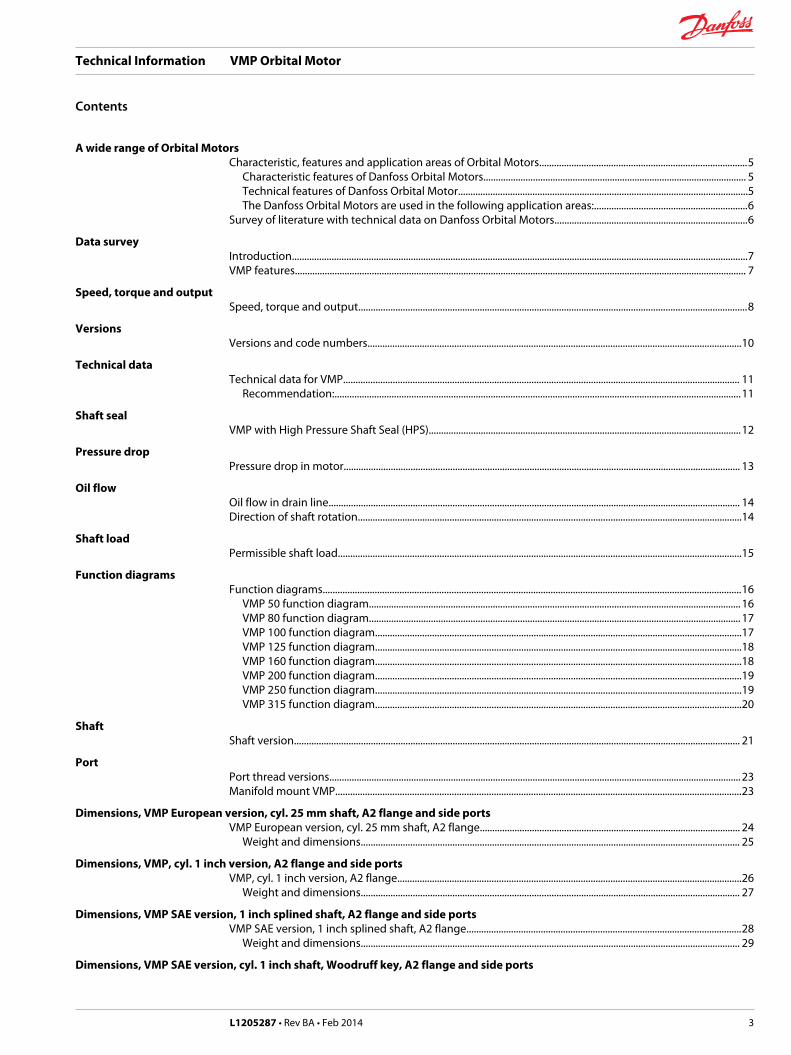
A wide range of Orbital MotorsCharacteristic, features and application areas of Orbital Motors....................................................................................5
Characteristic features of Danfoss Orbital Motors.......................................................................................................... 5Technical features of Danfoss Orbital Motor.....................................................................................................................5The Danfoss Orbital Motors are used in the following application areas:..............................................................6
Survey of literature with technical data on Danfoss Orbital Motors..............................................................................6
Data surveyIntroduction........................................................................................................................................................................................7VMP features...................................................................................................................................................................................... 7
Speed, torque and outputSpeed, torque and output.............................................................................................................................................................8
VersionsVersions and code numbers.......................................................................................................................................................10
Technical dataTechnical data for VMP................................................................................................................................................................ 11
Recommendation:....................................................................................................................................................................11
Shaft sealVMP with High Pressure Shaft Seal (HPS)..............................................................................................................................12
Pressure dropPressure drop in motor................................................................................................................................................................ 13
Oil flowOil flow in drain line...................................................................................................................................................................... 14Direction of shaft rotation...........................................................................................................................................................14
Shaft loadPermissible shaft load...................................................................................................................................................................15
Function diagramsFunction diagrams.........................................................................................................................................................................16
VMP 50 function diagram...................................................................................................................................................... 16VMP 80 function diagram...................................................................................................................................................... 17VMP 100 function diagram....................................................................................................................................................17VMP 125 function diagram....................................................................................................................................................18VMP 160 function diagram....................................................................................................................................................18VMP 200 function diagram....................................................................................................................................................19VMP 250 function diagram....................................................................................................................................................19VMP 315 function diagram....................................................................................................................................................20
ShaftShaft version.................................................................................................................................................................................... 21
PortPort thread versions......................................................................................................................................................................23Manifold mount VMP....................................................................................................................................................................23
Dimensions, VMP European version, cyl. 25 mm shaft, A2 flange and side portsVMP European version, cyl. 25 mm shaft, A2 flange......................................................................................................... 24
Weight and dimensions......................................................................................................................................................... 25
Dimensions, VMP, cyl. 1 inch version, A2 flange and side portsVMP, cyl. 1 inch version, A2 flange...........................................................................................................................................26
Weight and dimensions......................................................................................................................................................... 27
Dimensions, VMP SAE version, 1 inch splined shaft, A2 flange and side portsVMP SAE version, 1 inch splined shaft, A2 flange...............................................................................................................28
Weight and dimensions......................................................................................................................................................... 29
Dimensions, VMP SAE version, cyl. 1 inch shaft, Woodruff key, A2 flange and side ports
Technical Information VMP Orbital Motor
Contents
L1205287 • Rev BA • Feb 2014 3
VMP SAE version, cyl. 1 inch shaft, Woodruff key, A2 flange..........................................................................................30Weight and dimensions......................................................................................................................................................... 31
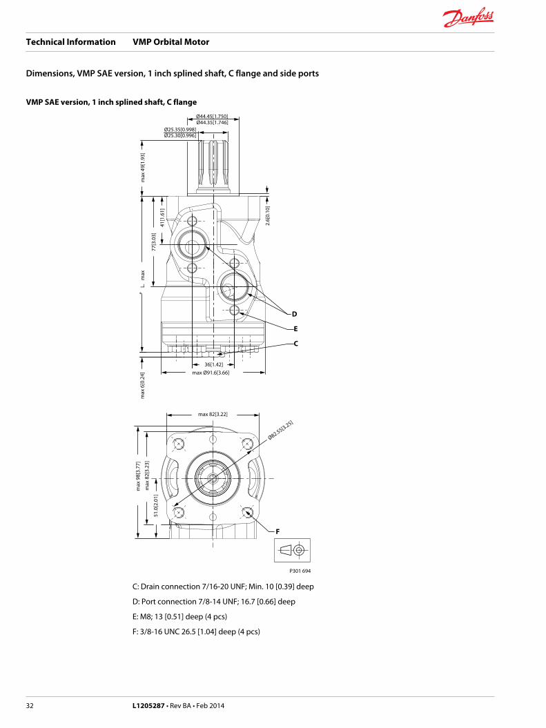
Dimensions, VMP SAE version, 1 inch splined shaft, C flange and side portsVMP SAE version, 1 inch splined shaft, C flange................................................................................................................. 32
Weight and dimensions......................................................................................................................................................... 33
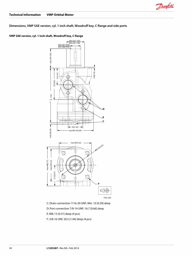
Dimensions, VMP SAE version, cyl. 1 inch shaft, Woodruff key, C flange and side portsVMP SAE version, cyl. 1 inch shaft, Woodruff key, C flange............................................................................................ 34
Weight and dimensions......................................................................................................................................................... 35
Technical Information VMP Orbital Motor
Contents
4 L1205287 • Rev BA • Feb 2014
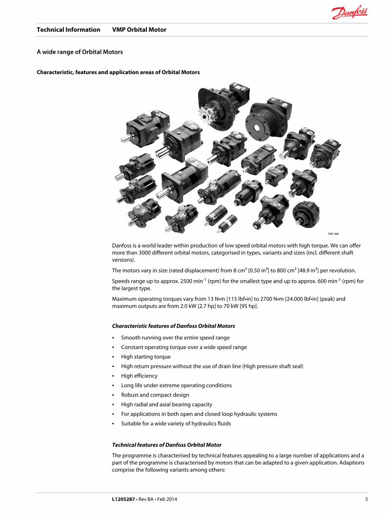
Characteristic, features and application areas of Orbital Motors
Danfoss is a world leader within production of low speed orbital motors with high torque. We can offermore than 3000 different orbital motors, categorised in types, variants and sizes (incl. different shaftversions).
The motors vary in size (rated displacement) from 8 cm³ [0.50 in³] to 800 cm³ [48.9 in³] per revolution.
Speeds range up to approx. 2500 min-1 (rpm) for the smallest type and up to approx. 600 min-1 (rpm) forthe largest type.
Maximum operating torques vary from 13 N•m [115 lbf•in] to 2700 N•m [24.000 lbf•in] (peak) andmaximum outputs are from 2.0 kW [2.7 hp] to 70 kW [95 hp].
Characteristic features of Danfoss Orbital Motors
• Smooth running over the entire speed range
• Constant operating torque over a wide speed range
• High starting torque
• High return pressure without the use of drain line (High pressure shaft seal)
• High efficiency
• Long life under extreme operating conditions
• Robust and compact design
• High radial and axial bearing capacity
• For applications in both open and closed loop hydraulic systems
• Suitable for a wide variety of hydraulics fluids
Technical features of Danfoss Orbital Motor
The programme is characterised by technical features appealing to a large number of applications and apart of the programme is characterised by motors that can be adapted to a given application. Adaptionscomprise the following variants among others:
Technical Information VMP Orbital Motor
A wide range of Orbital Motors
L1205287 • Rev BA • Feb 2014 5
• Motors with corrosion resistant parts
• Wheel motors with recessed mounting flange
• OMP, OMR- motors with needle bearing
• OMR motor in low leakage version
• OMR motors in a super low leakage version
• Short motors without bearings
• Ultra short motors
• Motors with integrated positive holding brake
• Motors with integrated negative holding brake
• Motors with integrated flushing valve
• Motors with speed sensor
• Motors with tacho connection
• All motors are available with black finish paint
The Danfoss Orbital Motors are used in the following application areas:
• Construction equipment
• Agricultural equipment
• Material handling & Lifting equipment
• Forestry equipment
• Lawn and turf equipment
• Special purpose
• Machine tools and stationary equipment
• Marine equipment
Survey of literature with technical data on Danfoss Orbital Motors
Detailed data on all Danfoss Orbital Motors can be found in our motor catalogue, which is divided intomore individual subcatalogues:
• General information on Danfoss Orbital Motors: function, use, selection of orbital motor, hydraulicsystems, etc.
• Technical data on small motors: OML and OMM
• Technical data on medium sized motors: OMP, OMR, OMH
• Technical data on medium sized motors: DH and DS
• Technical data on medium sized motors: OMEW
• Technical data on medium sized motors: VMP
• Technical data on medium sized motors: VMR
• Technical data on large motors: OMS, OMT and OMV
• Technical data on large motors: TMT
• Technical data on large motors: TMV
A general survey brochure on Danfoss Orbital Motors gives a quick motor reference based on power,torque, speed and capabilities.
Technical Information VMP Orbital Motor
A wide range of Orbital Motors
6 L1205287 • Rev BA • Feb 2014
Introduction
By introducing the VMP, Danfoss is introducing an Orbital Motor in the new V-Series. In order to meet thedemands for motors that have the right duty cycle and efficiency capabilities for a given function,Danfoss now has 3 Orbital Motor Series:
T-Series – The Highest Torque
Leading performance with a long lifetime makes light work of the heaviest duties. Offering pressurecapability up to 350 bar [5076 psi] and high starting torque, the T-Series is the energy-efficient choice forthe toughest working environments.
O-Series – The Flexible Choice
The O-Series is flexible beyond compare. Delivering premium power across the board, these motorscover small to large, medium to heavy-duty needs with pressure capability up to 275 bar [3990 psi].Robust, reliable and designed to fulfill the latest emissions standards.
V-Series – The Core Solution
The V-Series is your quality benchmark in the medium duty market. Based on proven technology, thesereliable motors will reduce your overall system costs while adding value to your machine. Perfect formany tasks.
VMP features
• High pressure shaft seal• Proven orbital motor design• 3-chamber motor design• Suitable for medium and low duty
Technical Information VMP Orbital Motor
Data survey
L1205287 • Rev BA • Feb 2014 7
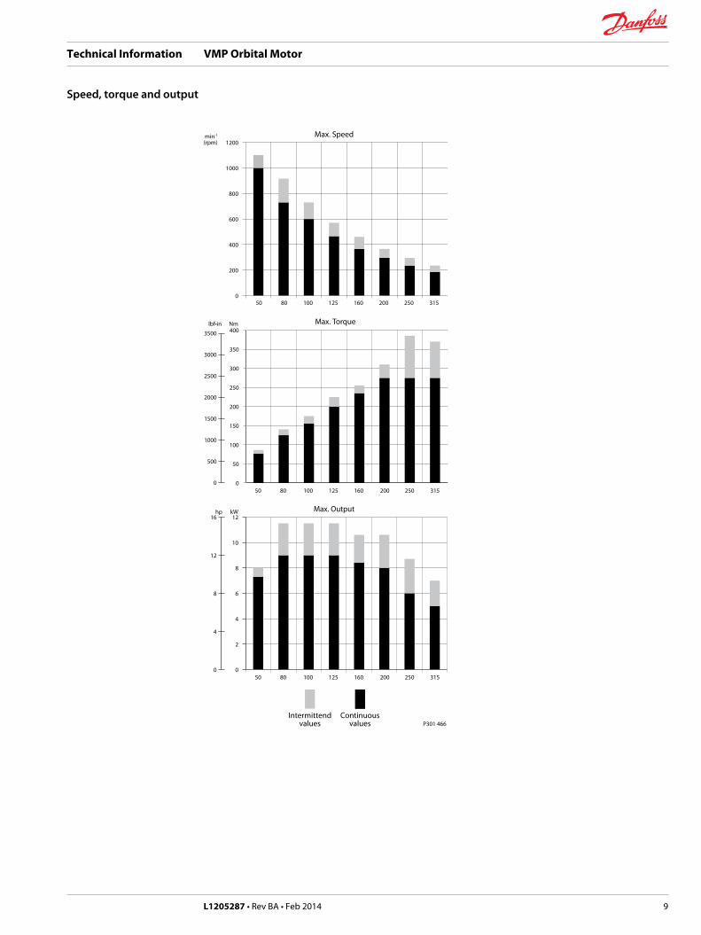
Speed, torque and output
The bar diagrams, are useful for a quick selection of relevant motor size for the application. The finalmotor size can be determined by using the function diagram.
The function diagrams are based on actual tests on a representative number of motors from ourproduction. The diagrams apply to a return pressure between 5 and 10 bar [75 and 150 psi] when usingmineral based hydraulic oil with a viscosity of 35 mm²/s [165 SUS] and a temperature of 50°C [120°F]. Forfurther explanation concerning how to read and use the function diagrams, please consult the paragraph"Selection of motor size" in the technical information "General" 520L0232.
Technical Information VMP Orbital Motor
Speed, torque and output
8 L1205287 • Rev BA • Feb 2014
P301 466Intermittend
valuesContinuous
values
hp kW
lbf•in Nm
min-1
(rpm)
1216
12
8
4
0
3500
3000
2500
2000
1500
1000
500
0
0
2
4
6
8
10
50 80 100 125 160 200 250 315
Max. Output
0
50
100
150
200
250
300
350
400
50 80 100 125 160 200 250 315
Max. Torque
0
200
400
600
800
1000
1200
50 80 100 125 160 200 250 315
Max. Speed
Technical Information VMP Orbital Motor
Speed, torque and output
L1205287 • Rev BA • Feb 2014 9
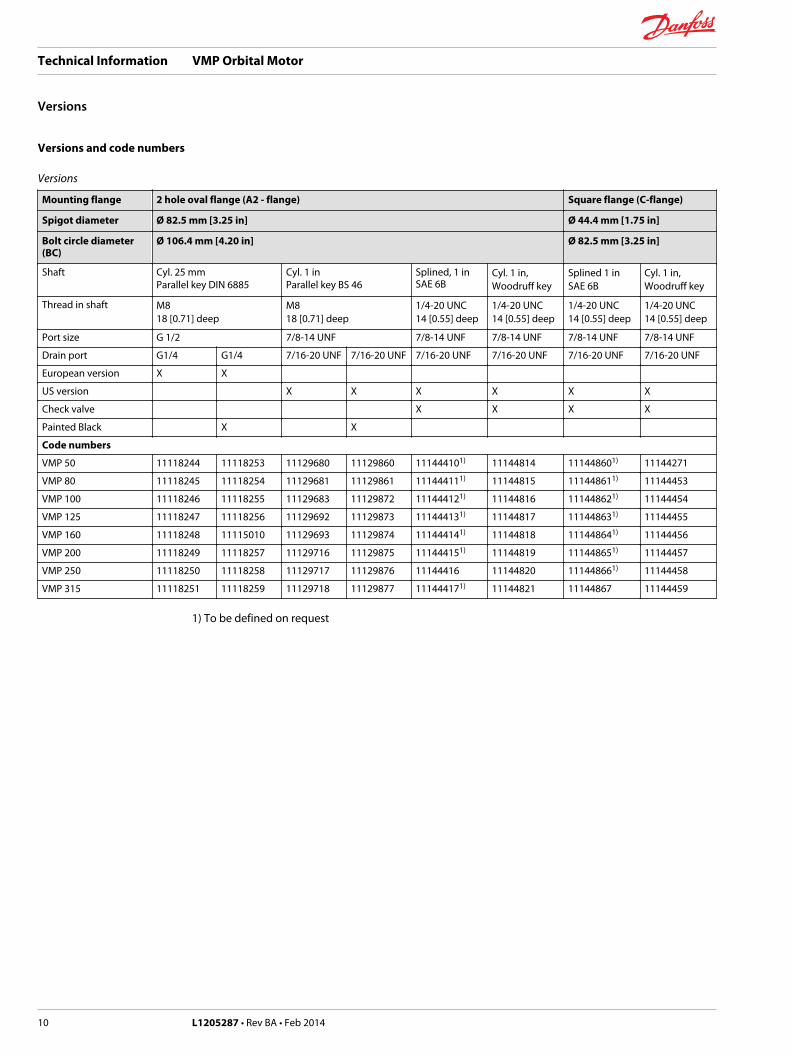
Versions and code numbers
Versions
Mounting flange 2 hole oval flange (A2 - flange) Square flange (C-flange)
Spigot diameter Ø 82.5 mm [3.25 in] Ø 44.4 mm [1.75 in]
Bolt circle diameter(BC)
Ø 106.4 mm [4.20 in] Ø 82.5 mm [3.25 in]
Shaft Cyl. 25 mmParallel key DIN 6885
Cyl. 1 inParallel key BS 46
Splined, 1 inSAE 6B
Cyl. 1 in,Woodruff key
Splined 1 inSAE 6B
Cyl. 1 in,Woodruff key
Thread in shaft M818 [0.71] deep
M818 [0.71] deep
1/4-20 UNC14 [0.55] deep
1/4-20 UNC14 [0.55] deep
1/4-20 UNC14 [0.55] deep
1/4-20 UNC14 [0.55] deep
Port size G 1/2 7/8-14 UNF 7/8-14 UNF 7/8-14 UNF 7/8-14 UNF 7/8-14 UNF
Drain port G1/4 G1/4 7/16-20 UNF 7/16-20 UNF 7/16-20 UNF 7/16-20 UNF 7/16-20 UNF 7/16-20 UNF
European version X X
US version X X X X X X
Check valve X X X X
Painted Black X X
Code numbers
VMP 50 11118244 11118253 11129680 11129860 111444101) 11144814 111448601) 11144271
VMP 80 11118245 11118254 11129681 11129861 111444111) 11144815 111448611) 11144453
VMP 100 11118246 11118255 11129683 11129872 111444121) 11144816 111448621) 11144454
VMP 125 11118247 11118256 11129692 11129873 111444131) 11144817 111448631) 11144455
VMP 160 11118248 11115010 11129693 11129874 111444141) 11144818 111448641) 11144456
VMP 200 11118249 11118257 11129716 11129875 111444151) 11144819 111448651) 11144457
VMP 250 11118250 11118258 11129717 11129876 11144416 11144820 111448661) 11144458
VMP 315 11118251 11118259 11129718 11129877 111444171) 11144821 11144867 11144459
1) To be defined on request
Technical Information VMP Orbital Motor
Versions
10 L1205287 • Rev BA • Feb 2014
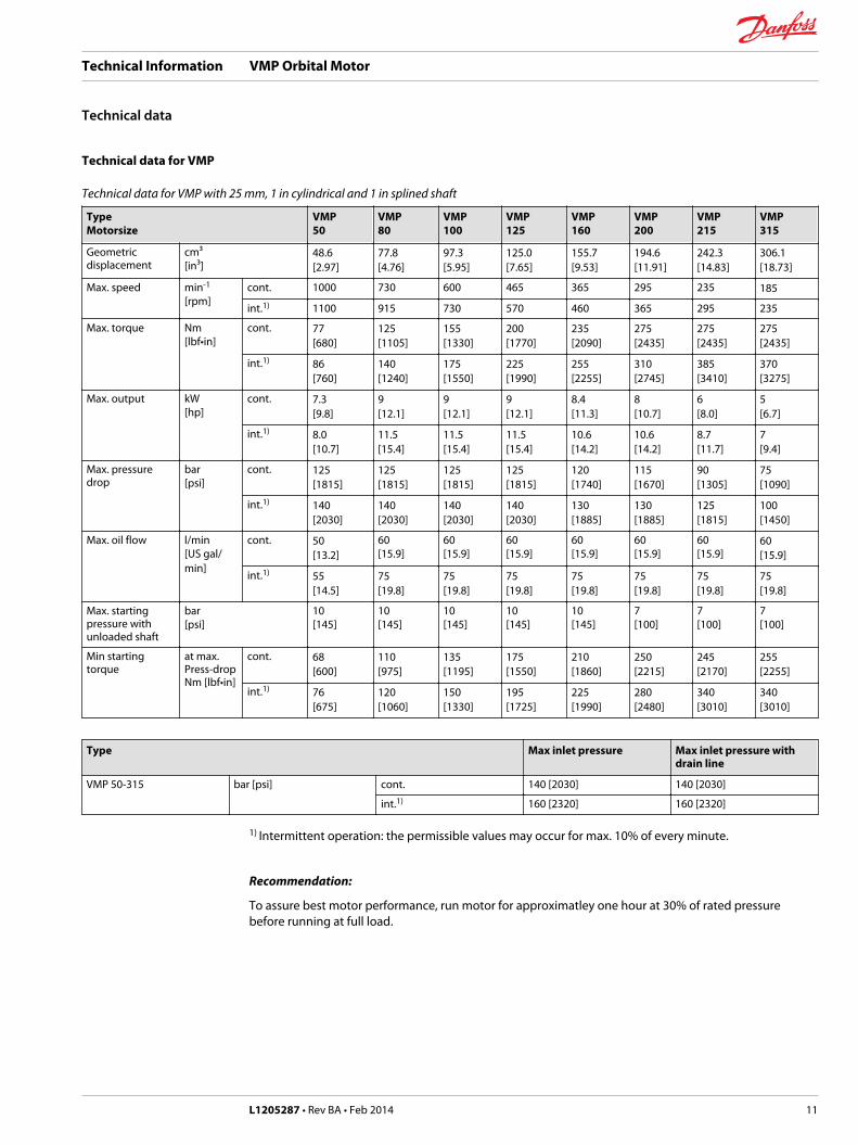
Technical data for VMP
Technical data for VMP with 25 mm, 1 in cylindrical and 1 in splined shaft
TypeMotorsize
VMP50
VMP80
VMP100
VMP125
VMP160
VMP200
VMP215
VMP315
Geometricdisplacement
cm³[in³]
48.6[2.97]
77.8[4.76]
97.3[5.95]
125.0[7.65]
155.7[9.53]
194.6[11.91]
242.3[14.83]
306.1[18.73]
Max. speed min-1
[rpm]cont. 1000 730 600 465 365 295 235 185
int.1) 1100 915 730 570 460 365 295 235
Max. torque Nm[lbf•in]
cont. 77[680]
125[1105]
155[1330]
200[1770]
235[2090]
275[2435]
275[2435]
275[2435]
int.1) 86[760]
140[1240]
175[1550]
225[1990]
255[2255]
310[2745]
385[3410]
370[3275]
Max. output kW[hp]
cont. 7.3[9.8]
9[12.1]
9[12.1]
9[12.1]
8.4[11.3]
8[10.7]
6[8.0]
5[6.7]
int.1) 8.0[10.7]
11.5[15.4]
11.5[15.4]
11.5[15.4]
10.6[14.2]
10.6[14.2]
8.7[11.7]
7[9.4]
Max. pressuredrop
bar[psi]
cont. 125[1815]
125[1815]
125[1815]
125[1815]
120[1740]
115[1670]
90[1305]
75[1090]
int.1) 140[2030]
140[2030]
140[2030]
140[2030]
130[1885]
130[1885]
125[1815]
100[1450]
Max. oil flow l/min[US gal/min]
cont. 50[13.2]
60[15.9]
60[15.9]
60[15.9]
60[15.9]
60[15.9]
60[15.9]
60[15.9]
int.1) 55[14.5]
75[19.8]
75[19.8]
75[19.8]
75[19.8]
75[19.8]
75[19.8]
75[19.8]
Max. startingpressure withunloaded shaft
bar[psi]
10[145]
10[145]
10[145]
10[145]
10[145]
7[100]
7[100]
7[100]
Min startingtorque
at max.Press-dropNm [lbf•in]
cont. 68[600]
110[975]
135[1195]
175[1550]
210[1860]
250[2215]
245[2170]
255[2255]
int.1) 76[675]
120[1060]
150[1330]
195[1725]
225[1990]
280[2480]
340[3010]
340[3010]
Type Max inlet pressure Max inlet pressure withdrain line
VMP 50-315 bar [psi] cont. 140 [2030] 140 [2030]
int.1) 160 [2320] 160 [2320]
1) Intermittent operation: the permissible values may occur for max. 10% of every minute.
Recommendation:
To assure best motor performance, run motor for approximatley one hour at 30% of rated pressurebefore running at full load.
Technical Information VMP Orbital Motor
Technical data
L1205287 • Rev BA • Feb 2014 11
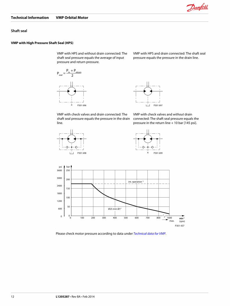
VMP with High Pressure Shaft Seal (HPS)
VMP with HPS and without drain connected: Theshaft seal pressure equals the average of inputpressure and return pressure.
VMP with HPS and drain connected: The shaft sealpressure equals the pressure in the drain line.
Pseal
Pin + Preturn
2 =
P301 696 P301 697
VMP with check valves and drain connected: Theshaft seal pressure equals the pressure in the drainline.
VMP with check valves and without drainconnected: The shaft seal pressure equals thepressure in the return line + 10 bar [145 psi].
P301 698 P301 699
bar250
200
150
100
50
00 100 200 300 400 500 600 700 800 1600
P301 437
Ø25 mm-Ø1”
max.min-1
int. operation 1)
psi3600
3000
2400
1800
1200
600
0min-1
(rpm)
Please check motor pressure according to data under Technical data for VMP.
Technical Information VMP Orbital Motor
Shaft seal
12 L1205287 • Rev BA • Feb 2014
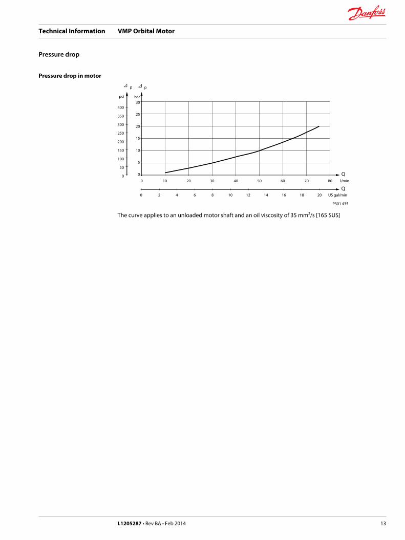
Pressure drop in motor
bar30
25
20
15
10
5
0
0 10 20 30 40 50 60 70 80 l/min
P301 435
Q
p
psi
400
350
300
250
200
150
100
50
0
0 2 4 6 8 10 12 14 16 18 20 US gal/minQ
p
The curve applies to an unloaded motor shaft and an oil viscosity of 35 mm²/s [165 SUS]
Technical Information VMP Orbital Motor
Pressure drop
L1205287 • Rev BA • Feb 2014 13
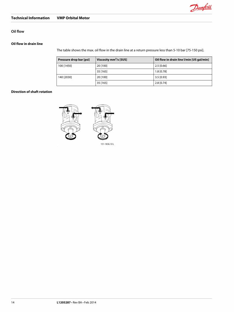
Oil flow in drain line
The table shows the max. oil flow in the drain line at a return pressure less than 5-10 bar [75-150 psi].
Pressure drop bar [psi] Viscosity mm²/s [SUS] Oil flow in drain line l/min [US gal/min]
100 [1450] 20 [100] 2.5 [0.66]
35 [165] 1.8 [0.78]
140 [2030] 20 [100] 3.5 [0.93]
35 [165] 2.8 [0.74]
Direction of shaft rotation
151-1836.10 L
Technical Information VMP Orbital Motor
Oil flow
14 L1205287 • Rev BA • Feb 2014
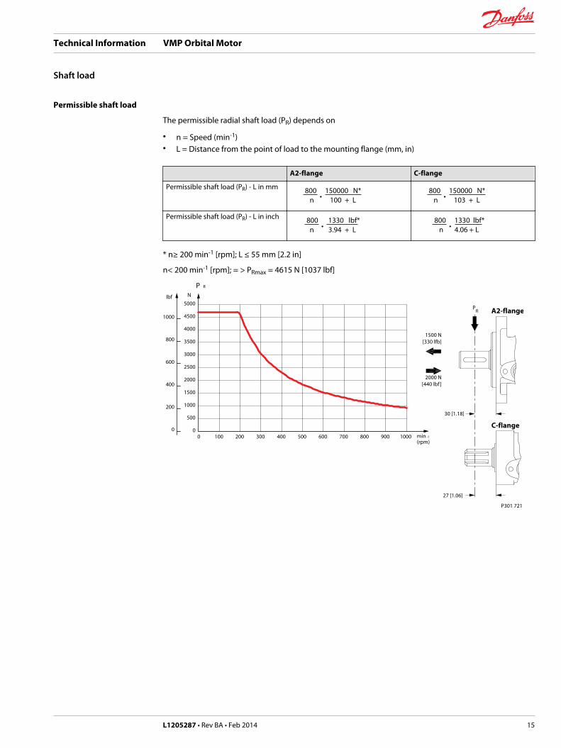
Permissible shaft load
The permissible radial shaft load (PR) depends on
• n = Speed (min-1)• L = Distance from the point of load to the mounting flange (mm, in)
A2-flange C-flange
Permissible shaft load (PR) - L in mm 800 • 150000 N*
n 100 + L 800
• 150000 N*
n 103 + L
Permissible shaft load (PR) - L in inch 800 • 1330 lbf*
n 3.94 + L 800
• 1330 lbf*
n 4.06 + L
* n≥ 200 min-1 [rpm]; L ≤ 55 mm [2.2 in]
n< 200 min-1 [rpm]; = > PRmax = 4615 N [1037 lbf]
0
500
1000
1500
2000
2500
3000
3500
4000
4500
5000
0 100 200 300 400 500 600 700 800 900 1000 min -1
(rpm)
1500 N[330 lfb]
2000 N[440 lbf ]
N
P R
1000
800
600
400
200
0
lbf
30 [1.18]
PR
C-flange
A2-flange
27 [1.06]
P301 721
Technical Information VMP Orbital Motor
Shaft load
L1205287 • Rev BA • Feb 2014 15
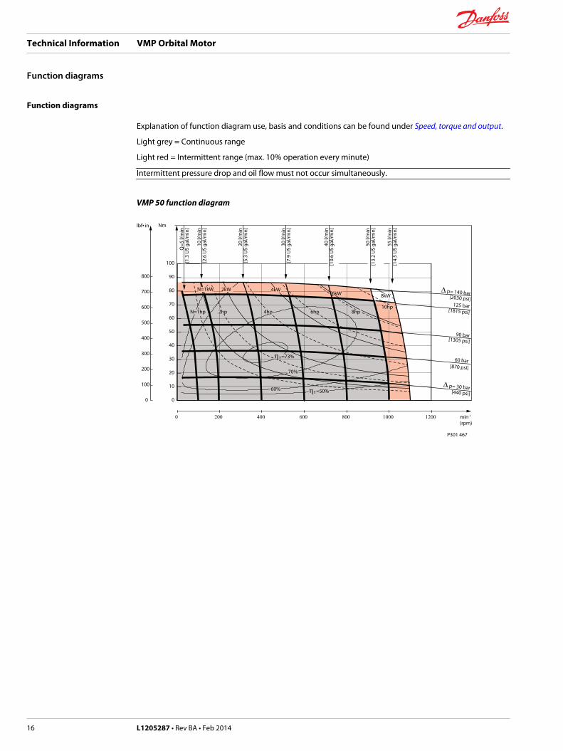
Function diagrams
Explanation of function diagram use, basis and conditions can be found under Speed, torque and output.
Light grey = Continuous range
Light red = Intermittent range (max. 10% operation every minute)
Intermittent pressure drop and oil flow must not occur simultaneously.
VMP 50 function diagram
0
10
20
30
40
50
60
70
80
90
100
0
100
200
300
400
500
600
700
800
VMP 50lbf• in Nm
P301 467
min-1
(rpm)
Q=5
l/m
in[1
.3 U
S ga
l/min
]
10 l/
min
[2.6
US
gal/m
in]
20 l/
min
[5.3
US
gal/m
in]
30 l/
min
[7.9
US
gal/m
in]
40 l/
min
[10.
6 U
S ga
l/min
]
50 l/
min
[13.
2 U
S ga
l/min
]
55 l/
min
[14.
5 U
S ga
l/min
]
∆ p= 30 bar
[1305 psi]
[2030 psi]
[1815 psi]
[440 psi]
[870 psi]
60 bar
90 bar
125 bar
∆ p= 140 bar
N=1hp 4hp 8hp10hp
6hp
70%
6kW 8kW
η t =73%
η t =50%60%
N=1kW 4kW
2hp
2kW
0 200 400 600 800 1000 1200
Technical Information VMP Orbital Motor
Function diagrams
16 L1205287 • Rev BA • Feb 2014
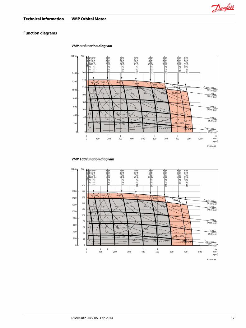
VMP 80 function diagram
0
20
40
60
80
100
120
140
160
0
200
400
600
800
1000
1200
1400
VMP 80lbf• in Nm
0 100 200 300 400 500 600 700 800 900 1000
P301 468
min-1
(rpm)
Q=5
l/m
in[1
.3 U
S ga
l/min
]10
l/m
in[2
.6 U
S ga
l/min
]
20 l/
min
[5.3
US
gal/m
in]
30 l/
min
[7.9
US
gal/m
in]
40 l/
min
[10.
6 U
S ga
l/min
]
50 l/
min
[13.
2 U
S ga
l/min
]
60 l/
min
[15.
9 U
S ga
l/min
]
70 l/
min
[18.
5US
gal/m
in]
Q=7
5 l/m
in[1
9.8
US
gal/m
in]
∆ p= 30 bar
[1305 psi]
[2030 psi]
[1815 psi]
[440 psi]
[870 psi]
60 bar
90 bar
125 bar
∆ p= 140 bar
N=1hp 4hp 10hp N=12hp8hp6hp
73% 70%
6kW 8kW10kW
η t =74%
η t =50%60%
N=1kW 4kW
2hp
2kW
VMP 100 function diagram
0
20
40
60
80
100
120
140
160
180
200
0
200
400
600
800
1000
1200
1400
1600
VMP 100lbf• in Nm
0 100 200 300 400 500 600 700 800
P301 469
min-1
(rpm)
Q=5
l/m
in[1
.3 U
S ga
l/min
]10
l/m
in[2
.6 U
S ga
l/min
]
20 l/
min
[5.3
US
gal/m
in]
30 l/
min
[7.9
US
gal/m
in]
40 l/
min
[10.
6 U
S ga
l/min
]
50 l/
min
[13.
2 U
S ga
l/min
]
60 l/
min
[15.
9 U
S ga
l/min
]
70 l/
min
[18.
5US
gal/m
in]
Q=7
5 l/m
in[1
9.8
US
gal/m
in]
∆ p= 30 bar
[1305 psi]
[2030 psi]
[1815 psi]
[440 psi]
[870 psi]
60 bar
90 bar
125 bar
∆ p= 140 bar
N=1hp 4hp 10hp N=12hp8hp6hp
73% 70%
6kW 8kW10kW
η t =74%
η t =50%60%
N=1kW 4kW
2hp
2kW
Technical Information VMP Orbital Motor
Function diagrams
L1205287 • Rev BA • Feb 2014 17
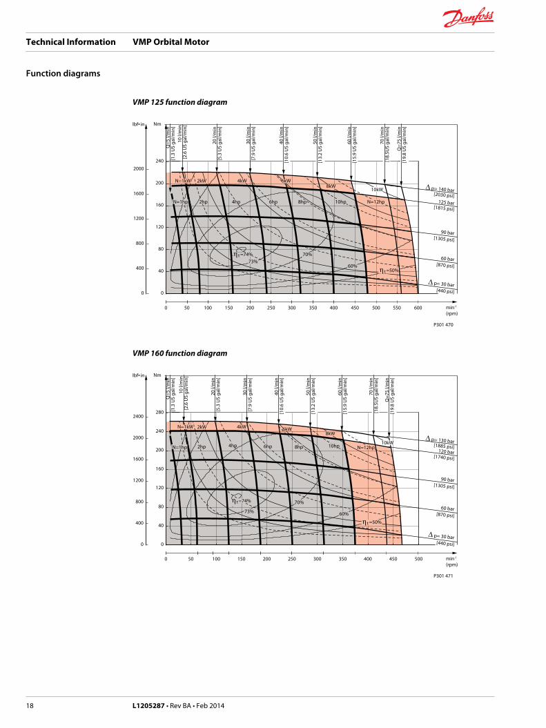
VMP 125 function diagram
0
40
80
120
160
200
240
0
400
800
1200
1600
2000
VMP 125lbf• in Nm
0 50 100 150 200 250 300 350 400 450 500 550 600
P301 470
min-1
(rpm)
Q=5
l/m
in[1
.3 U
S ga
l/min
]10
l/m
in[2
.6 U
S ga
l/min
]
20 l/
min
[5.3
US
gal/m
in]
30 l/
min
[7.9
US
gal/m
in]
40 l/
min
[10.
6 U
S ga
l/min
]
50 l/
min
[13.
2 U
S ga
l/min
]
60 l/
min
[15.
9 U
S ga
l/min
]
70 l/
min
[18.
5US
gal/m
in]
Q=7
5 l/m
in[1
9.8
US
gal/m
in]
∆ p= 30 bar
[1305 psi]
[2030 psi]
[1815 psi]
[440 psi]
[870 psi]
60 bar
90 bar
125 bar
∆ p= 140 bar
N=1hp 4hp 10hp N=12hp8hp6hp
73%70%
6kW8kW
10kW
η t =74%
η t =50%60%
N=1kW 4kW
2hp
2kW
VMP 160 function diagram
0
40
80
120
160
200
240
280
0
400
800
1200
1600
2000
2400
VMP 160lbf• in Nm
0 50 100 150 200 250 300 350 400 450 500
P301 471
min-1
(rpm)
Q=5
l/m
in[1
.3 U
S ga
l/min
]
10 l/
min
[2.6
US
gal/m
in]
20 l/
min
[5.3
US
gal/m
in]
30 l/
min
[7.9
US
gal/m
in]
40 l/
min
[10.
6 U
S ga
l/min
]
50 l/
min
[13.
2 U
S ga
l/min
]
60 l/
min
[15.
9 U
S ga
l/min
]
70 l/
min
[18.
5US
gal/m
in]
Q=7
5 l/m
in[1
9.8
US
gal/m
in]
∆ p= 30 bar
[1305 psi]
[1885 psi]
[1740 psi]
[440 psi]
[870 psi]
60 bar
90 bar
120 bar
∆ p= 130 barN=1hp 4hp 10hp N=12hp8hp6hp
73%
70%
6kW8kW
10kW
η t =74%
η t =50%
60%
N=1kW 4kW
2hp
2kW
Technical Information VMP Orbital Motor
Function diagrams
18 L1205287 • Rev BA • Feb 2014
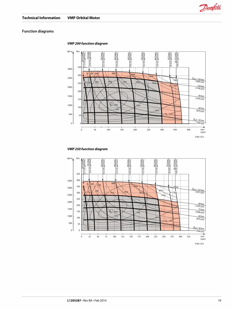
VMP 200 function diagram
0
50
100
150
200
250
300
350
0
500
1000
1500
2000
2500
3000
VMP 200lbf• in Nm
0 50 100 150 200 250 300 350 400
P301 472
min-1
(rpm)
Q=5
l/m
in[1
.3 U
S ga
l/min
]
10 l/
min
[2.6
US
gal/m
in]
20 l/
min
[5.3
US
gal/m
in]
30 l/
min
[7.9
US
gal/m
in]
40 l/
min
[10.
6 U
S ga
l/min
]
50 l/
min
[13.
2 U
S ga
l/min
]
60 l/
min
[15.
9 U
S ga
l/min
]
70 l/
min
[18.
5US
gal/m
in]
Q=7
5 l/m
in[1
9.8
US
gal/m
in]
∆ p= 30 bar
[1305 psi]
[1885 psi]
[1740 psi]
[440 psi]
[870 psi]
60 bar
90 bar
120 bar
∆ p= 130 barN=1hp 4hp
10hpN=12hp
8hp6hp
73%
70%
6kW8kW
10kW
η t =74%
η t =50%
60%
N=1kW 4kW
2hp
2kW
VMP 250 function diagram
0
50
100
150
200
250
300
350
400
450
0
500
1000
1500
2000
2500
3000
3500
VMP 250lbf• in Nm
0 25 50 75 100 125 150 175 200 225 250 275 300 325
P301 473
min-1
(rpm)
Q=5
l/m
in[1
.3 U
S ga
l/min
]
10 l/
min
[2.6
US
gal/m
in]
20 l/
min
[5.3
US
gal/m
in]
30 l/
min
[7.9
US
gal/m
in]
40 l/
min
[10.
6 U
S ga
l/min
]
50 l/
min
[13.
2 U
S ga
l/min
]
60 l/
min
[15.
9 U
S ga
l/min
]
70 l/
min
[18.
5US
gal/m
in]
Q=7
5 l/m
in[1
9.8
US
gal/m
in]
∆ p= 30 bar
[1088 psi]
[1815 psi]
[1305 psi]
[440 psi]
[870 psi]
60 bar
75 bar
90 bar
∆ p= 125 barN=1hp 4hp
10hpN=12hp8hp6hp
73%
70%
6kW
8kW
10kW
η t =74%
η t =50%
60%
N=1kW 4kW
2hp
2kW
Technical Information VMP Orbital Motor
Function diagrams
L1205287 • Rev BA • Feb 2014 19
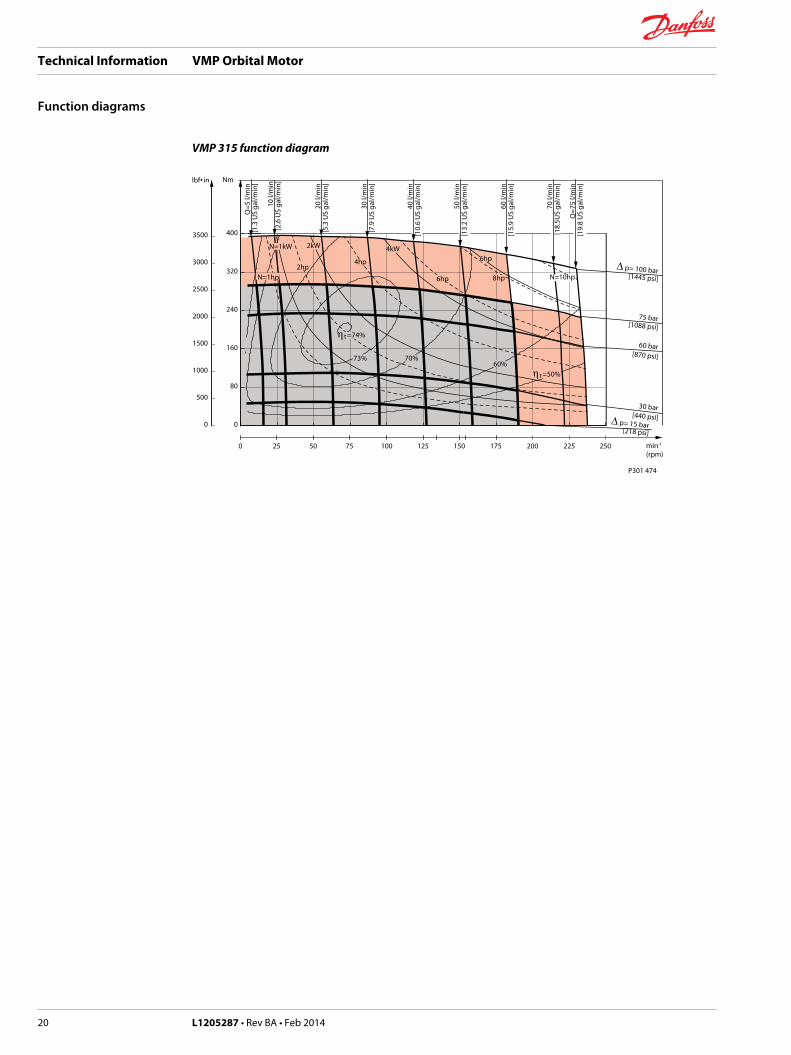
VMP 315 function diagram
0
80
160
240
320
400
0
500
1000
1500
2000
2500
3000
3500
VMP 315lbf• in Nm
0 25 50 75 100 125 150 175 200 225 250
P301 474
min-1
(rpm)
Q=5
l/m
in[1
.3 U
S ga
l/min
]
10 l/
min
[2.6
US
gal/m
in]
20 l/
min
[5.3
US
gal/m
in]
30 l/
min
[7.9
US
gal/m
in]
40 l/
min
[10.
6 U
S ga
l/min
]
50 l/
min
[13.
2 U
S ga
l/min
]
60 l/
min
[15.
9 U
S ga
l/min
]
70 l/
min
[18.
5US
gal/m
in]
Q=7
5 l/m
in[1
9.8
US
gal/m
in]
∆ p= 15 bar
[870 psi]
[1445 psi]
[1088 psi]
[218 psi]
[440 psi]
30 bar
60 bar
75 bar
∆ p= 100 barN=1hp
4hp
N=10hp8hp6hp
73% 70%
6hp
η t =74%
η t =50%60%
N=1kW 4kW
2hp
2kW
Technical Information VMP Orbital Motor
Function diagrams
20 L1205287 • Rev BA • Feb 2014
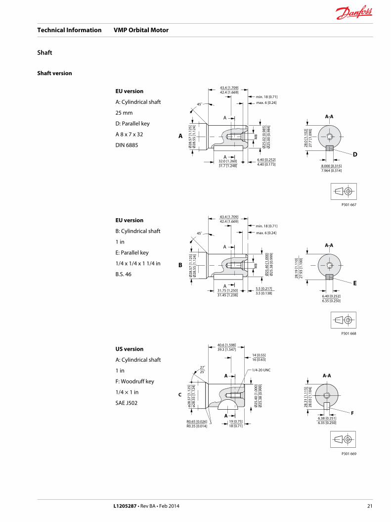
Shaft version
EU version
A: Cylindrical shaft
25 mm
D: Parallel key
A 8 x 7 x 32
DIN 6885
8.000 [0.315]7.964 [0.314]
43.4 [1.709]42.4 [1.669]
max. 6 [0.24]min. 18 [0.71]
45˚
32.0 [1.260]31.7 [1.248]
6.40 [0.252]4.40 [0.173]
M8
Ø28
.57
[1.1
25]
Ø28
.55
[1.1
24]
28.0
[1.1
02]
27.7
[1.0
90]
Ø25
.02
[0.9
85]
Ø25
.00
[0.9
84]
D
A-A
P301 667
A
A
A
EU version
B: Cylindrical shaft
1 in
E: Parallel key
1/4 x 1/4 x 1 1/4 in
B.S. 46
6.40 [0.252]6.35 [0.250]
28.1
9 [1
.110
]27
.93
[1.1
00]
E
A-A
P301 668
43.4 [1.709]42.4 [1.669]
max. 6 [0.24]
min. 18 [0.71]
45˚
31.75 [1.250]31.45 [1.238]
5.5 [0.217]3.5 [0.138]
M8
Ø28
.57
[1.1
25]
Ø28
.55
[1.1
24]
Ø25
.40
[1.0
00]
Ø25
.38
[0.9
99]
B
A
A
US version
A: Cylindrical shaft
1 in
F: Woodruff key
1/4 × 1 in
SAE J502
P301 669
19 [0.75]18 [0.71]
14 [0.55]16 [0.63]
A-AA
A F
C
40.6 [1.598]39.3 [1.547]
R0.65 [0.026]R0.35 [0.014]
27˚25˚ 1/4-20 UNC
6.38 [0.251]6.35 [0.250]
28.3
1 [1
.115
]28
.03
[1.1
04]
Ø25
.40
[1.0
00]
Ø25
.38
[0.9
99]
ø28.
57 [1
.125
]ø2
8.55
[1.1
24]
Technical Information VMP Orbital Motor
Shaft
L1205287 • Rev BA • Feb 2014 21
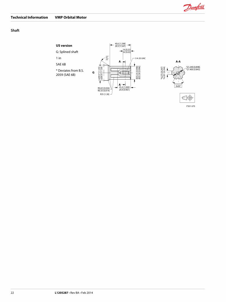
US version
G: Splined shaft
1 in
SAE 6B
* Deviates from B.S.2059 (SAE 6B)
P301 670
25.4 [1.000]24.4 [0.961]
R35 [1.38]
14 [0.55]16 [0.63]
A-AA
A
G
40.6 [1.598]39.3 [1.547]
R0.65 [0.026]R0.35 [0.014]
27˚25˚
6x60˚
1/4-20 UNC
*21.540 [0.848]*21.400 [0.843]
*6.2
75 [0
.247
]*6
.201
[0.2
44]
Ø25
.35
[0.9
98]
Ø25
.30
[0.9
96]
ø28.
57 [1
.125
]ø2
8.55
[1.1
24]
Technical Information VMP Orbital Motor
Shaft
22 L1205287 • Rev BA • Feb 2014
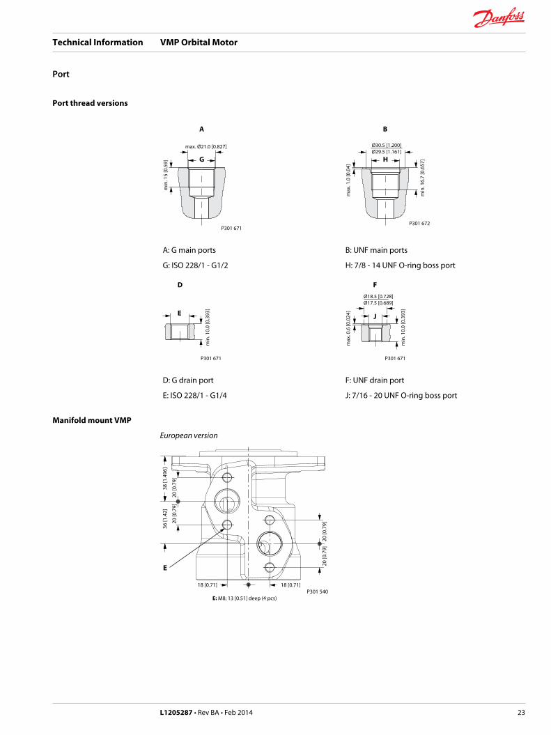
Port thread versions
G
A
max. Ø21.0 [0.827]
min
. 15
[0.5
9]
P301 671
H
B
Ø30.5 [1.200]Ø29.5 [1.161]
min
. 16.
7 [0
.657
]
max
. 1.0
[0.0
4]
P301 672
A: G main ports
G: ISO 228/1 - G1/2
B: UNF main ports
H: 7/8 - 14 UNF O-ring boss port
D
E
min
. 10.
0 [0
.393
]
P301 671
F
J
Ø18.5 [0.728]Ø17.5 [0.689]
min
. 10.
0 [0
.393
]
max
. 0.6
[0.0
24]
P301 671
D: G drain port
E: ISO 228/1 - G1/4
F: UNF drain port
J: 7/16 - 20 UNF O-ring boss port
Manifold mount VMP
European version
18 [0.71] 18 [0.71]
20 [0
.79]
20 [0
.79]
20 [0
.79]
20 [0
.79]
36 [1
.42]
38 [1
.496
]
P301 540
E
E: M8; 13 [0.51] deep (4 pcs)
Technical Information VMP Orbital Motor
Port
L1205287 • Rev BA • Feb 2014 23
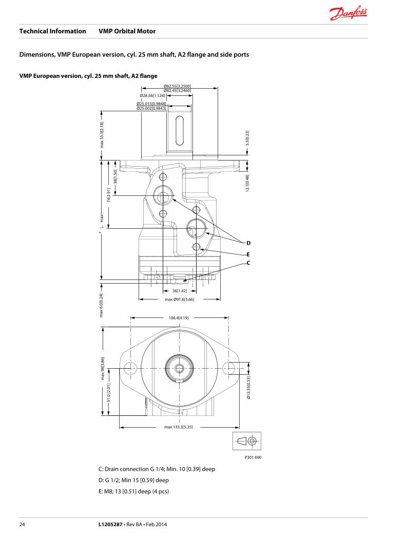
VMP European version, cyl. 25 mm shaft, A2 flange
max
98[
3.86
]51
.0 [2
.01]
max 133.3[5.25]
106.4[4.19]
Ø13
.55[
0.53
]D
EC
max
55.
3[2.
18]
*m
axL.
max
6.0
[0.2
4]
Ø82.45[3.2460]Ø82.55[3.2500]
Ø25.015[0.9848]Ø25.002[0.9843]
Ø28.56[1.124]
38[1
.50]
74[2
.91]
max Ø91.6[3.66]
36[1.42]
P301 690
5.5[
0.22
]12
.1[0
.48]
C: Drain connection G 1/4; Min. 10 [0.39] deep
D: G 1/2; Min 15 [0.59] deep
E: M8; 13 [0.51] deep (4 pcs)
Technical Information VMP Orbital Motor
Dimensions, VMP European version, cyl. 25 mm shaft, A2 flange and side ports
24 L1205287 • Rev BA • Feb 2014

Weight and dimensions
Type *Lmax mm [in] Weight kg [lb]
VMP 50 max 132.0 [5.20] 4.9 [10.8]
VMP 80 max 136.0 [5.35] 5.0 [11.0]
VMP 100 max 138.5 [5.45] 5.2 [11.5]
VMP 125 max 142.2 [5.60] 5.3 [11.7]
VMP 160 max 146.3 [5.76] 5.5 [12.1]
VMP 200 max 151.5 [5.96] 5.7 [12.6]
VMP 250 max 158.0 [6.22] 5.9 [13.0]
VMP 315 max 166.5 [6.56] 6.2 [13.7]
Technical Information VMP Orbital Motor
Dimensions, VMP European version, cyl. 25 mm shaft, A2 flange and side ports
L1205287 • Rev BA • Feb 2014 25
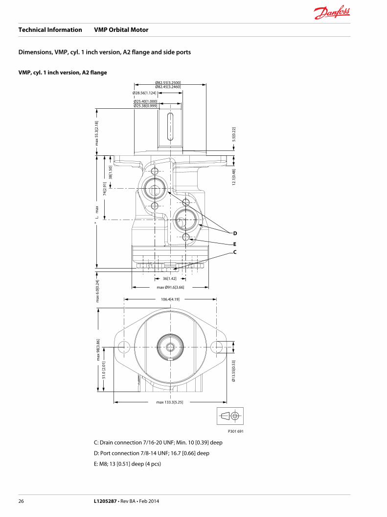
VMP, cyl. 1 inch version, A2 flange
max
98[
3.86
]51
.0 [2
.01]
max 133.3[5.25]
106.4[4.19]
Ø13
.55[
0.53
]
max
55.
3[2.
18]
D
EC
*m
axL.
max
6.0
[0.2
4]
Ø82.45[3.2460]Ø82.55[3.2500]
Ø28.56[1.124]
max Ø91.6[3.66]
36[1.42]
38[1
.50]
74[2
.91]
Ø25.38[0.999]Ø25.40[1.000]
P301 691
5.5[
0.22
]12
.1[0
.48]
C: Drain connection 7/16-20 UNF; Min. 10 [0.39] deep
D: Port connection 7/8-14 UNF; 16.7 [0.66] deep
E: M8; 13 [0.51] deep (4 pcs)
Technical Information VMP Orbital Motor
Dimensions, VMP, cyl. 1 inch version, A2 flange and side ports
26 L1205287 • Rev BA • Feb 2014

Weight and dimensions
Type *Lmax mm [in] Weight kg [lb]
VMP 50 max 132.0 [5.20] 4.9 [10.8]
VMP 80 max 136.0 [5.35] 5.0 [11.0]
VMP 100 max 138.5 [5.45] 5.2 [11.5]
VMP 125 max 142.2 [5.60] 5.3 [11.7]
VMP 160 max 146.3 [5.76] 5.5 [12.1]
VMP 200 max 151.5 [5.96] 5.7 [12.6]
VMP 250 max 158.0 [6.22] 5.9 [13.0]
VMP 315 max 166.5 [6.56] 6.2 [13.7]
Technical Information VMP Orbital Motor
Dimensions, VMP, cyl. 1 inch version, A2 flange and side ports
L1205287 • Rev BA • Feb 2014 27
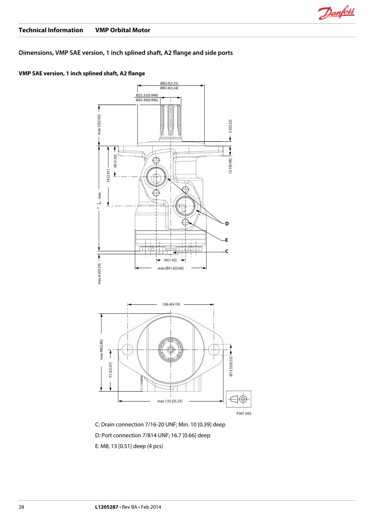
VMP SAE version, 1 inch splined shaft, A2 flange
max
98[
3.86
]
max 133.3[5.25]
106.4[4.19]
Ø13
.55[
0.53
]
max
52[
2.05
]*
max
L.m
ax 6
.0[0
.24]
Ø82.4[3.24]Ø82.6[3.25]
38 [1
.50]
74 [2
.91]
max Ø91.6[3.66]
36[1.42]
Ø25.30[0.996]Ø25.35[0.998]
D
E
C
51.0
[2.0
1]
5.5[
0.22
]12
.1[0
.48]
P301 692
C: Drain connection 7/16-20 UNF; Min. 10 [0.39] deep
D: Port connection 7/814 UNF; 16.7 [0.66] deep
E: M8; 13 [0.51] deep (4 pcs)
Technical Information VMP Orbital Motor
Dimensions, VMP SAE version, 1 inch splined shaft, A2 flange and side ports
28 L1205287 • Rev BA • Feb 2014
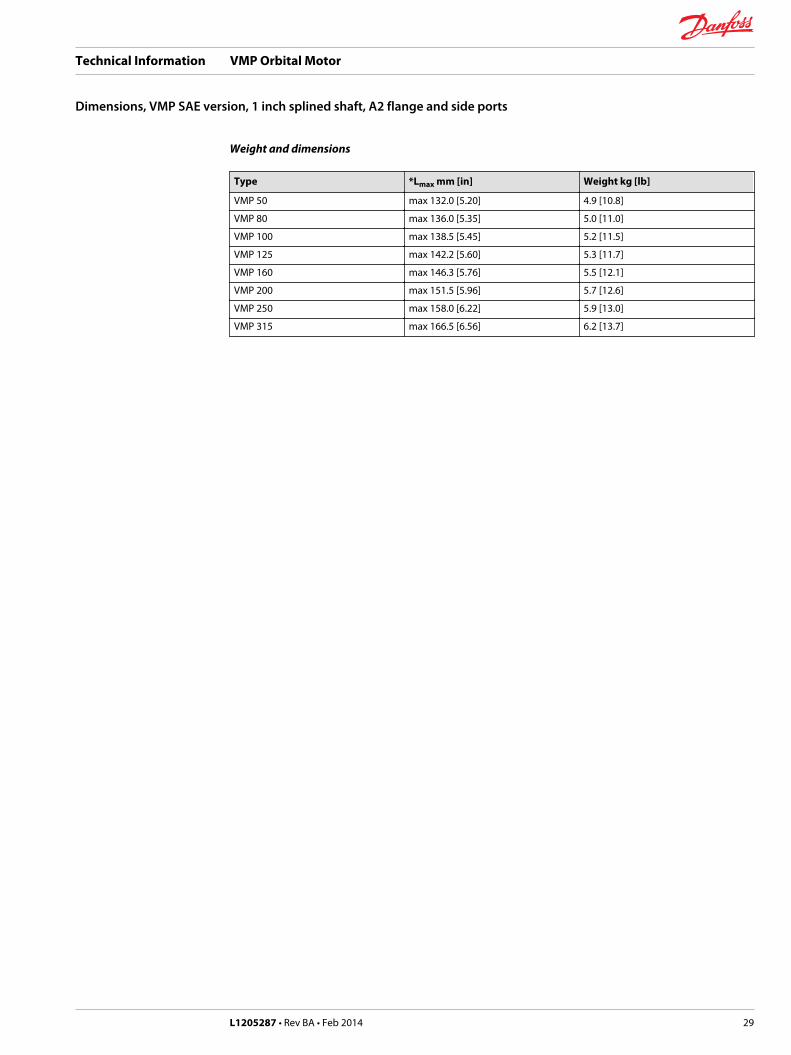
Weight and dimensions
Type *Lmax mm [in] Weight kg [lb]
VMP 50 max 132.0 [5.20] 4.9 [10.8]
VMP 80 max 136.0 [5.35] 5.0 [11.0]
VMP 100 max 138.5 [5.45] 5.2 [11.5]
VMP 125 max 142.2 [5.60] 5.3 [11.7]
VMP 160 max 146.3 [5.76] 5.5 [12.1]
VMP 200 max 151.5 [5.96] 5.7 [12.6]
VMP 250 max 158.0 [6.22] 5.9 [13.0]
VMP 315 max 166.5 [6.56] 6.2 [13.7]
Technical Information VMP Orbital Motor
Dimensions, VMP SAE version, 1 inch splined shaft, A2 flange and side ports
L1205287 • Rev BA • Feb 2014 29
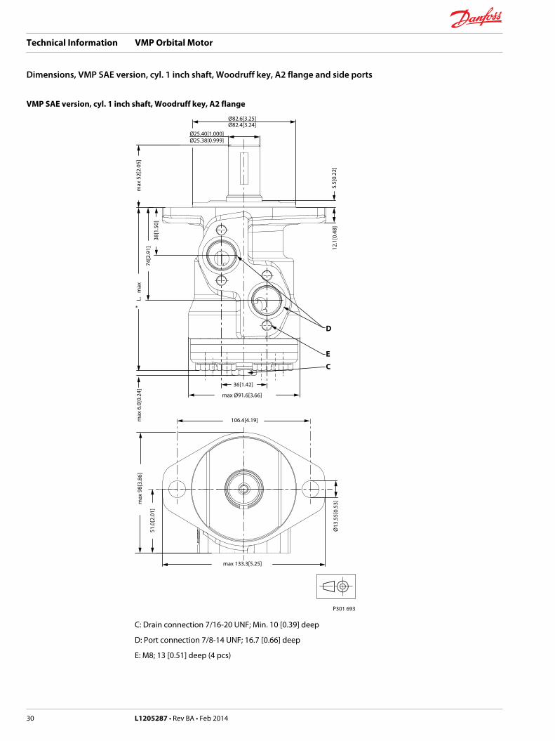
VMP SAE version, cyl. 1 inch shaft, Woodruff key, A2 flange
max 133.3[5.25]
106.4[4.19]
Ø13
.55[
0.53
]
38[1
.50]
74[2
.91]
max Ø91.6[3.66]
36[1.42]
Ø25.38[0.999]Ø25.40[1.000]
max
52[
2.05
]*
max
L.m
ax 6
.0[0
.24]
D
E
C
Ø82.4[3.24]Ø82.6[3.25]
5.5[
0.22
]12
.1[0
.48]
max
98[
3.86
]
51.0
[2.0
1]
P301 693
C: Drain connection 7/16-20 UNF; Min. 10 [0.39] deep
D: Port connection 7/8-14 UNF; 16.7 [0.66] deep
E: M8; 13 [0.51] deep (4 pcs)
Technical Information VMP Orbital Motor
Dimensions, VMP SAE version, cyl. 1 inch shaft, Woodruff key, A2 flange and side ports
30 L1205287 • Rev BA • Feb 2014

Weight and dimensions
Type *Lmax mm [in] Weight kg [lb]
VMP 50 max 132.0 [5.20] 4.9 [10.8]
VMP 80 max 136.0 [5.35] 5.0 [11.0]
VMP 100 max 138.5 [5.45] 5.2 [11.5]
VMP 125 max 142.2 [5.60] 5.3 [11.7]
VMP 160 max 146.3 [5.76] 5.5 [12.1]
VMP 200 max 151.5 [5.96] 5.7 [12.6]
VMP 250 max 158.0 [6.22] 5.9 [13.0]
VMP 315 max 166.5 [6.56] 6.2 [13.7]
Technical Information VMP Orbital Motor
Dimensions, VMP SAE version, cyl. 1 inch shaft, Woodruff key, A2 flange and side ports
L1205287 • Rev BA • Feb 2014 31
VMP SAE version, 1 inch splined shaft, C flange
*m
axL.
max
6[0
.24]
max
49[
1.93
]m
ax 9
8[3.
77]
max
82[
3.23
]
max 82[3.22]
Ø82.55[3.25]
F
41[1
.61]
77[3
.03]
Ø25.30[0.996]Ø25.35[0.998]
max Ø91.6[3.66]36[1.42]
2.6[
0.10
]
Ø44.45[1.750]Ø44.35[1.746]
D
E
C
51.0
[2.0
1]
P301 694
C: Drain connection 7/16-20 UNF; Min. 10 [0.39] deep
D: Port connection 7/8-14 UNF; 16.7 [0.66] deep
E: M8; 13 [0.51] deep (4 pcs)
F: 3/8-16 UNC 26.5 [1.04] deep (4 pcs)
Technical Information VMP Orbital Motor
Dimensions, VMP SAE version, 1 inch splined shaft, C flange and side ports
32 L1205287 • Rev BA • Feb 2014

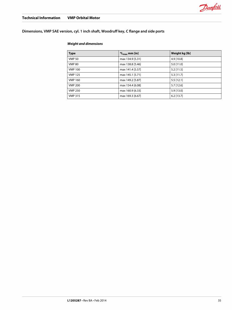
Weight and dimensions
Type *Lmax mm [in] Weight kg [lb]
VMP 50 max 134.9 [5.31] 4.9 [10.8]
VMP 80 max 138.8 [5.46] 5.0 [11.0]
VMP 100 max 141.4 [5.57] 5.2 [11.5]
VMP 125 max 145.1 [5.71] 5.3 [11.7]
VMP 160 max 149.2 [5.87] 5.5 [12.1]
VMP 200 max 154.4 [6.08] 5.7 [12.6]
VMP 250 max 160.9 [6.33] 5.9 [13.0]
VMP 315 max 169.3 [6.67] 6.2 [13.7]
Technical Information VMP Orbital Motor
Dimensions, VMP SAE version, 1 inch splined shaft, C flange and side ports
L1205287 • Rev BA • Feb 2014 33
VMP SAE version, cyl. 1 inch shaft, Woodruff key, C flange
*m
axL.
max 82[3.22]
F
Ø82.55[3.25]
41[1
.61]
77[3
.03]
max Ø91.6[3.66]
36[1.42]
Ø44.45[1.750]
2.6[
0.10
]
Ø25.38[0.999]Ø25.40[1.000]
Ø44.35[1.746]
max
98[
3.77
]
max
82[
3.23
]
51.0
[2.0
1]
D
EC
max
49[
1.93
]m
ax 6
[0.2
4]
P301 695
C: Drain connection 7/16-20 UNF; Min. 10 [0.39] deep
D: Port connection 7/8-14 UNF; 16.7 [0.66] deep
E: M8; 13 [0.51] deep (4 pcs)
F: 3/8-16 UNC 26.5 [1.04] deep (4 pcs)
Technical Information VMP Orbital Motor
Dimensions, VMP SAE version, cyl. 1 inch shaft, Woodruff key, C flange and side ports
34 L1205287 • Rev BA • Feb 2014
Weight and dimensions
Type *Lmax mm [in] Weight kg [lb]
VMP 50 max 134.9 [5.31] 4.9 [10.8]
VMP 80 max 138.8 [5.46] 5.0 [11.0]
VMP 100 max 141.4 [5.57] 5.2 [11.5]
VMP 125 max 145.1 [5.71] 5.3 [11.7]
VMP 160 max 149.2 [5.87] 5.5 [12.1]
VMP 200 max 154.4 [6.08] 5.7 [12.6]
VMP 250 max 160.9 [6.33] 5.9 [13.0]
VMP 315 max 169.3 [6.67] 6.2 [13.7]
Technical Information VMP Orbital Motor
Dimensions, VMP SAE version, cyl. 1 inch shaft, Woodruff key, C flange and side ports
L1205287 • Rev BA • Feb 2014 35
Danfoss Power Solutions is a global manufacturer and supplier of high-quality hydraulic andelectronic components. We specialize in providing state-of-the-art technology and solutions thatexcel in the harsh operating conditions of the mobile off -highway market. Building on our extensive applications expertise, we work closely with our customers to ensure exceptional performance for a broad range of off -highway vehicles.
We help OEMs around the world speed up system development, reduce costs and bring vehicles tomarket faster.Danfoss – Your Strongest Partner in Mobile Hydraulics.
Go to www.powersolutions.danfoss.com for further product information.
Wherever off -highway vehicles are at work, so is Danfoss.
We off er expert worldwide support for our customers, ensuring the best possible solutions for outstanding performance. And with an extensive network of Global Service Partners, we also provide comprehensive global service for all of our components.
Please contact the Danfoss Power Solution representative nearest you.
Local address:
Danfoss Power Solutions GmbH & Co. OHGKrokamp 35D-24539 Neumünster, GermanyPhone: +49 4321 871 0
Danfoss Power Solutions ApSNordborgvej 81DK-6430 Nordborg, DenmarkPhone: +45 7488 2222
Danfoss Power Solutions US Company2800 East 13th StreetAmes, IA 50010, USAPhone: +1 515 239 6000
Danfoss Power Solutions(Shanghai) Co. Ltd.Building #22, No. 1000 Jin Hai RdJin Qiao, Pudong New DistrictShanghai, China 201206Phone: +86 21 3418 5200
Danfoss can accept no responsibility for possible errors in catalogues, brochures and other printed material. Danfoss reserves the right to alter its products without notice. This also applies toproducts already on order provided that such alterations can be made without subsequential changes being necessary in specifications already agreed.All trademarks in this material are property of the respective companies. Danfoss and the Danfoss logotype are trademarks of Danfoss A/S. All rights reserved.
L1205287 • Rev BA • Feb 2014 www.danfoss.com © Danfoss A/S, 2014
Products we off er:
• Bent Axis Motors
• Closed Circuit Axial Piston Pumps and Motors
• Displays
• Electrohydraulic Power Steering
• Electrohydraulics
• Hydraulic Power Steering
• Integrated Systems
• Joysticks and Control Handles
• Microcontrollers and Software
• Open Circuit Axial Piston Pumps
• Orbital Motors
• PLUS+1® GUIDE
• Proportional Valves
• Sensors
• Steering
• Transit Mixer Drives
Comatrolwww.comatrol.com
Schwarzmüller-Inverterwww.schwarzmueller-inverter.com
Turolla www.turollaocg.com
Valmovawww.valmova.com
Hydro-Gearwww.hydro-gear.com
Daikin-Sauer-Danfosswww.daikin-sauer-danfoss.com