VMDC Design Considerations - Cisco · Chapter 2 VMDC Design Considerations High Availability...
34
CHAPTER 2-1 Cisco Virtualized Multi-Tenant Data Center, Version 2.1 2 VMDC Design Considerations The Cisco VMDC 2.1 release highlights key design areas of network, compute, and storage with focus on the following: • “High Availability” section on page 2-1 • “Virtualized Multi-Tenancy” section on page 2-10 • “Performance and Scalability” section on page 2-15 • “Service Assurance” section on page 2-22 High Availability High Availability is key design point for building a virtualized cloud environment. Eliminating planned downtime and preventing unplanned downtime are key aspects in the design of the multi-tenant shared infrastructure. This section covers high availability design considerations and best practices related to the network, compute, and storage components in the VMDC 2.1 architecture. Network Availability Network availability is paramount to any organization running a virtualized data center service. It is strategic for disaster planning, as well as everyday operations, and ensures that tenants can reliably access application servers. The VMDC 2.1 infrastructure design is based on a three-tier model (core, aggregation, and access) as depicted in Figure 2-1.
Transcript of VMDC Design Considerations - Cisco · Chapter 2 VMDC Design Considerations High Availability...
Cisc
C H A P T E R 2
VMDC Design ConsiderationsThe Cisco VMDC 2.1 release highlights key design areas of network, compute, and storage with focus on the following:
• “High Availability” section on page 2-1
• “Virtualized Multi-Tenancy” section on page 2-10
• “Performance and Scalability” section on page 2-15
• “Service Assurance” section on page 2-22
High AvailabilityHigh Availability is key design point for building a virtualized cloud environment. Eliminating planned downtime and preventing unplanned downtime are key aspects in the design of the multi-tenant shared infrastructure. This section covers high availability design considerations and best practices related to the network, compute, and storage components in the VMDC 2.1 architecture.
Network AvailabilityNetwork availability is paramount to any organization running a virtualized data center service. It is strategic for disaster planning, as well as everyday operations, and ensures that tenants can reliably access application servers.
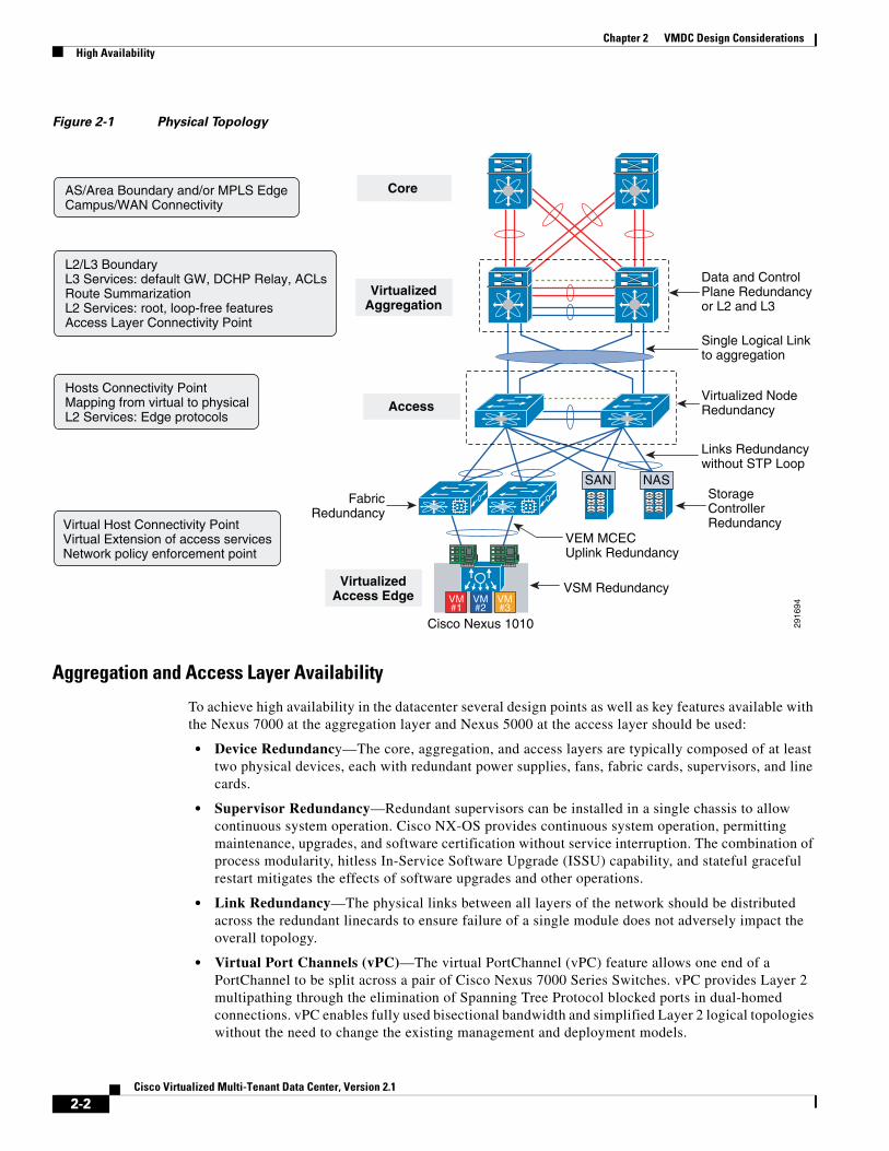
The VMDC 2.1 infrastructure design is based on a three-tier model (core, aggregation, and access) as depicted in Figure 2-1.
2-1o Virtualized Multi-Tenant Data Center, Version 2.1
Chapter 2 VMDC Design ConsiderationsHigh Availability
Figure 2-1 Physical Topology
Aggregation and Access Layer Availability
To achieve high availability in the datacenter several design points as well as key features available with the Nexus 7000 at the aggregation layer and Nexus 5000 at the access layer should be used:
• Device Redundancy—The core, aggregation, and access layers are typically composed of at least two physical devices, each with redundant power supplies, fans, fabric cards, supervisors, and line cards.
• Supervisor Redundancy—Redundant supervisors can be installed in a single chassis to allow continuous system operation. Cisco NX-OS provides continuous system operation, permitting maintenance, upgrades, and software certification without service interruption. The combination of process modularity, hitless In-Service Software Upgrade (ISSU) capability, and stateful graceful restart mitigates the effects of software upgrades and other operations.
• Link Redundancy—The physical links between all layers of the network should be distributed across the redundant linecards to ensure failure of a single module does not adversely impact the overall topology.
• Virtual Port Channels (vPC)—The virtual PortChannel (vPC) feature allows one end of a PortChannel to be split across a pair of Cisco Nexus 7000 Series Switches. vPC provides Layer 2 multipathing through the elimination of Spanning Tree Protocol blocked ports in dual-homed connections. vPC enables fully used bisectional bandwidth and simplified Layer 2 logical topologies without the need to change the existing management and deployment models.
VSM Redundancy
FabricRedundancy
VEM MCECUplink Redundancy
StorageControllerRedundancy
Links Redundancywithout STP Loop
Virtualized NodeRedundancy
Single Logical Linkto aggregation
Data and ControlPlane Redundancy or L2 and L3
AS/Area Boundary and/or MPLS EdgeCampus/WAN Connectivity
L2/L3 BoundaryL3 Services: default GW, DCHP Relay, ACLsRoute SummarizationL2 Services: root, loop-free featuresAccess Layer Connectivity Point
Virtual Host Connectivity PointVirtual Extension of access servicesNetwork policy enforcement point
Hosts Connectivity PointMapping from virtual to physicalL2 Services: Edge protocols
Cisco Nexus 1010
Core
Access
VirtualizedAggregation
VirtualizedAccess Edge
2916
94
SAN
VM#1
VM#2
VM#3
NAS
2-2Cisco Virtualized Multi-Tenant Data Center, Version 2.1
Chapter 2 VMDC Design ConsiderationsHigh Availability
• Multi-Chassis Ether Channels (MEC)—Multi-Chassis Ether Channels were used to connect the aggregation layer to the services layer. MEC allows for redundant routed paths between the aggregation switches and the services switches.
• Virtual Route and Forwarding (VRF)—Redundant VRF instances provide Layer 3 services for their associated tenant segments.
• Fast Convergence—Network convergence is optimized by providing tools and functions to make both failover and fallback transparent and fast. For example, Cisco NX-OS provides Spanning Tree Protocol enhancements such as Bridge Protocol Data Unit (BPDU) guard, loop guard, root guard, BPDU filters, and bridge assurance to help ensure the health of the Spanning Tree Protocol control plane; Unidirectional Link Detection (UDLD) Protocol; NSF graceful restart of routing protocols; millisecond timers for First-Hop Resiliency Protocol (FHRP); Shortest-Path First (SPF) optimizations such as link-state advertisement (LSA) pacing and incremental SPF; IEEE 802.3ad link aggregation with adjustable timers; and Bidirectional Forwarding Detection (BFD).
Nexus 1010 Deployment Options
Deployment of the Cisco Nexus 1010 offers many benefits. First, because the Cisco Nexus 1010 appliance is owned and operated by the network team, deployment no longer depends on collaboration with the network, storage, and virtualization operations teams. Instead, the Cisco Nexus 1010 can be installed and deployed in the same way as any networking device.
Another benefit is the flexibility of placement: the Cisco Nexus 1010 can be inserted into the network at various locations. The previous section discussed the four options for connecting the Cisco Nexus 1010 to the network. These methods can be used in various areas of the network. Typically, Cisco Nexus 1010 appliances are deployed in a central management domain. Often, this is where other network appliances, such as the Cisco Application Control Engine (ACE), Cisco Wide Area Application Services (WAAS), the NAM, etc. are deployed.
• For more information on the Cisco Nexus 1010 deployment follow the link below:
• http://www.cisco.com/en/US/partner/prod/collateral/switches/ps9441/ps9902/white_paper_c07-603623.html
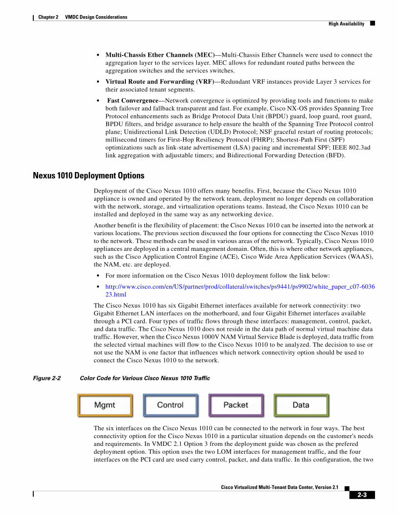
The Cisco Nexus 1010 has six Gigabit Ethernet interfaces available for network connectivity: two Gigabit Ethernet LAN interfaces on the motherboard, and four Gigabit Ethernet interfaces available through a PCI card. Four types of traffic flows through these interfaces: management, control, packet, and data traffic. The Cisco Nexus 1010 does not reside in the data path of normal virtual machine data traffic. However, when the Cisco Nexus 1000V NAM Virtual Service Blade is deployed, data traffic from the selected virtual machines will flow to the Cisco Nexus 1010 to be analyzed. The decision to use or not use the NAM is one factor that influences which network connectivity option should be used to connect the Cisco Nexus 1010 to the network.
Figure 2-2 Color Code for Various Cisco Nexus 1010 Traffic
The six interfaces on the Cisco Nexus 1010 can be connected to the network in four ways. The best connectivity option for the Cisco Nexus 1010 in a particular situation depends on the customer's needs and requirements. In VMDC 2.1 Option 3 from the deployment guide was chosen as the prefered deployment option. This option uses the two LOM interfaces for management traffic, and the four interfaces on the PCI card are used carry control, packet, and data traffic. In this configuration, the two
2-3Cisco Virtualized Multi-Tenant Data Center, Version 2.1
Chapter 2 VMDC Design ConsiderationsHigh Availability
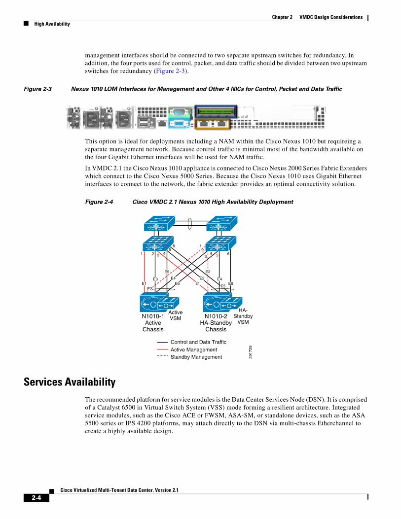
management interfaces should be connected to two separate upstream switches for redundancy. In addition, the four ports used for control, packet, and data traffic should be divided between two upstream switches for redundancy (Figure 2-3).
Figure 2-3 Nexus 1010 LOM Interfaces for Management and Other 4 NICs for Control, Packet and Data Traffic
This option is ideal for deployments including a NAM within the Cisco Nexus 1010 but requireing a separate management network. Because control traffic is minimal most of the bandwidth available on the four Gigabit Ethernet interfaces will be used for NAM traffic.
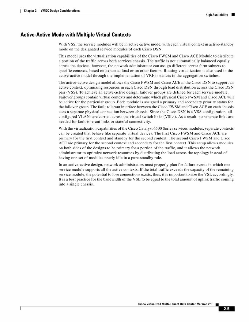
In VMDC 2.1 the Cisco Nexus 1010 appliance is connected to Cisco Nexus 2000 Series Fabric Extenders which connect to the Cisco Nexus 5000 Series. Because the Cisco Nexus 1010 uses Gigabit Ethernet interfaces to connect to the network, the fabric extender provides an optimal connectivity solution.
Figure 2-4 Cisco VMDC 2.1 Nexus 1010 High Availability Deployment
Services AvailabilityThe recommended platform for service modules is the Data Center Services Node (DSN). It is comprised of a Catalyst 6500 in Virtual Switch System (VSS) mode forming a resilient architecture. Integrated service modules, such as the Cisco ACE or FWSM, ASA-SM, or standalone devices, such as the ASA 5500 series or IPS 4200 platforms, may attach directly to the DSN via multi-chassis Etherchannel to create a highly available design.
2917
25
ActiveVSM
Control and Data Traffic
Active ManagementStandby Management
HA-Standby
VSM
E1
1 62 53 443
5 26 1
E6E2
E5
E3 E4
E5 E3
E6 E1E4 E2
N1010-1Active
Chassis
N1010-2HA-Standby
Chassis
2-4Cisco Virtualized Multi-Tenant Data Center, Version 2.1
Chapter 2 VMDC Design ConsiderationsHigh Availability
Active-Active Mode with Multiple Virtual Contexts
With VSS, the service modules will be in active-active mode, with each virtual context in active-standby mode on the designated service modules of each Cisco DSN.
This model uses the virtualization capabilities of the Cisco FWSM and Cisco ACE Module to distribute a portion of the traffic across both services chassis. The traffic is not automatically balanced equally across the devices; however, the network administrator can assign different server farm subnets to specific contexts, based on expected load or on other factors. Routing virtualization is also used in the active-active model through the implementation of VRF instances in the aggregation switches.
The active-active design model allows the Cisco FWSM and Cisco ACE in the Cisco DSN to support an active context, optimizing resources in each Cisco DSN through load distribution across the Cisco DSN pair (VSS). To achieve an active-active design, failover groups are defined for each service module. Failover groups contain virtual contexts and determine which physical Cisco FWSM and Cisco ACE will be active for the particular group. Each module is assigned a primary and secondary priority status for the failover group. The fault-tolerant interface between the Cisco FWSM and Cisco ACE on each chassis uses a separate physical connection between chassis. Since the Cisco DSN is a VSS configuration, all configured VLANs are carried across the virtual switch links (VSLs). As a result, no separate links are needed for fault-tolerant links or stateful connectivity.
With the virtualization capabilities of the Cisco Catalyst 6500 Series services modules, separate contexts can be created that behave like separate virtual devices. The first Cisco FWSM and Cisco ACE are primary for the first context and standby for the second context. The second Cisco FWSM and Cisco ACE are primary for the second context and secondary for the first context. This setup allows modules on both sides of the designs to be primary for a portion of the traffic, and it allows the network administrator to optimize network resources by distributing the load across the topology instead of having one set of modules nearly idle in a pure-standby role.
In an active-active design, network administrators must properly plan for failure events in which one service module supports all the active contexts. If the total traffic exceeds the capacity of the remaining service module, the potential to lose connections exists; thus, it is important to size the VSL accordingly. It is a best practice for the bandwidth of the VSL to be equal to the total amount of uplink traffic coming into a single chassis.
2-5Cisco Virtualized Multi-Tenant Data Center, Version 2.1
Chapter 2 VMDC Design ConsiderationsHigh Availability
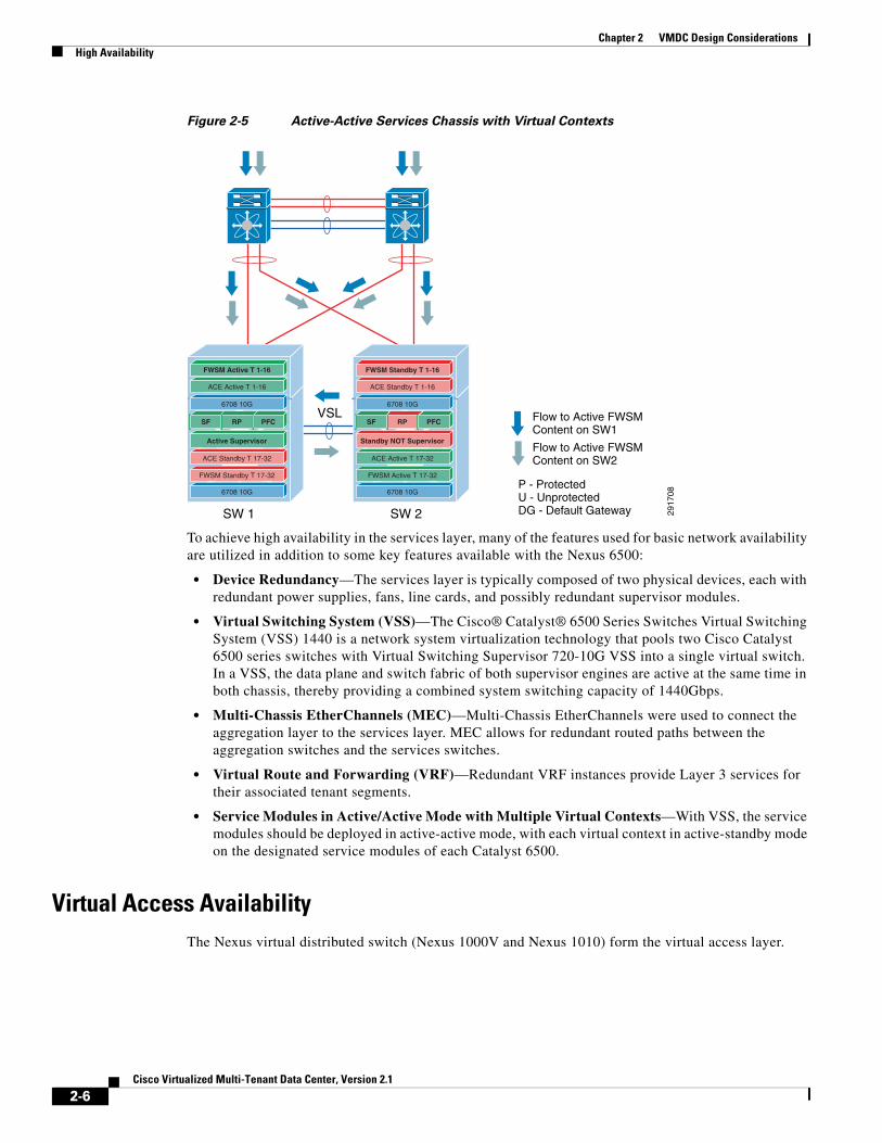
Figure 2-5 Active-Active Services Chassis with Virtual Contexts
To achieve high availability in the services layer, many of the features used for basic network availability are utilized in addition to some key features available with the Nexus 6500:
• Device Redundancy—The services layer is typically composed of two physical devices, each with redundant power supplies, fans, line cards, and possibly redundant supervisor modules.
• Virtual Switching System (VSS)—The Cisco® Catalyst® 6500 Series Switches Virtual Switching System (VSS) 1440 is a network system virtualization technology that pools two Cisco Catalyst 6500 series switches with Virtual Switching Supervisor 720-10G VSS into a single virtual switch. In a VSS, the data plane and switch fabric of both supervisor engines are active at the same time in both chassis, thereby providing a combined system switching capacity of 1440Gbps.
• Multi-Chassis EtherChannels (MEC)—Multi-Chassis EtherChannels were used to connect the aggregation layer to the services layer. MEC allows for redundant routed paths between the aggregation switches and the services switches.
• Virtual Route and Forwarding (VRF)—Redundant VRF instances provide Layer 3 services for their associated tenant segments.
• Service Modules in Active/Active Mode with Multiple Virtual Contexts—With VSS, the service modules should be deployed in active-active mode, with each virtual context in active-standby mode on the designated service modules of each Catalyst 6500.
Virtual Access AvailabilityThe Nexus virtual distributed switch (Nexus 1000V and Nexus 1010) form the virtual access layer.
VSL
SW 1 SW 2 2917
086708 10G
FWSM Standby T 17-32
ACE Standby T 17-32
Active Supervisor
RPSF PFC
6708 10G
ACE Active T 1-16
FWSM Active T 1-16
6708 10G
FWSM Active T 17-32
ACE Active T 17-32
Standby NOT Supervisor
RPSF PFC
6708 10G
ACE Standby T 1-16
FWSM Standby T 1-16
Flow to Active FWSMContent on SW1
Flow to Active FWSMContent on SW2
P - ProtectedU - UnprotectedDG - Default Gateway
2-6Cisco Virtualized Multi-Tenant Data Center, Version 2.1
Chapter 2 VMDC Design ConsiderationsHigh Availability
Nexus 1010 Manager High Availability
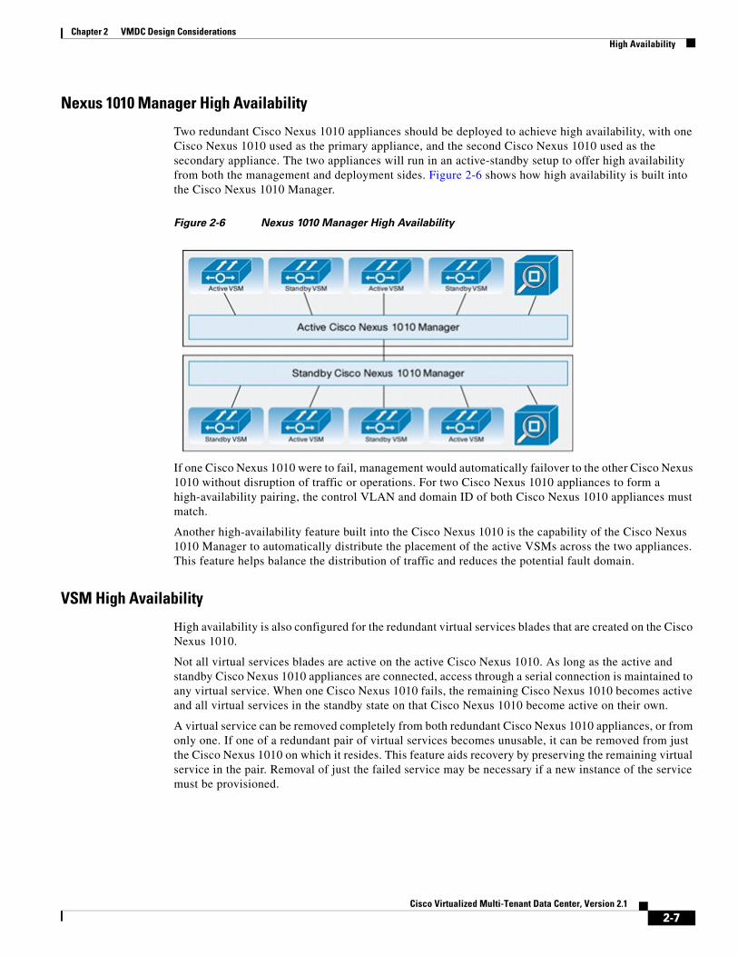
Two redundant Cisco Nexus 1010 appliances should be deployed to achieve high availability, with one Cisco Nexus 1010 used as the primary appliance, and the second Cisco Nexus 1010 used as the secondary appliance. The two appliances will run in an active-standby setup to offer high availability from both the management and deployment sides. Figure 2-6 shows how high availability is built into the Cisco Nexus 1010 Manager.
Figure 2-6 Nexus 1010 Manager High Availability
If one Cisco Nexus 1010 were to fail, management would automatically failover to the other Cisco Nexus 1010 without disruption of traffic or operations. For two Cisco Nexus 1010 appliances to form a high-availability pairing, the control VLAN and domain ID of both Cisco Nexus 1010 appliances must match.
Another high-availability feature built into the Cisco Nexus 1010 is the capability of the Cisco Nexus 1010 Manager to automatically distribute the placement of the active VSMs across the two appliances. This feature helps balance the distribution of traffic and reduces the potential fault domain.
VSM High Availability
High availability is also configured for the redundant virtual services blades that are created on the Cisco Nexus 1010.
Not all virtual services blades are active on the active Cisco Nexus 1010. As long as the active and standby Cisco Nexus 1010 appliances are connected, access through a serial connection is maintained to any virtual service. When one Cisco Nexus 1010 fails, the remaining Cisco Nexus 1010 becomes active and all virtual services in the standby state on that Cisco Nexus 1010 become active on their own.
A virtual service can be removed completely from both redundant Cisco Nexus 1010 appliances, or from only one. If one of a redundant pair of virtual services becomes unusable, it can be removed from just the Cisco Nexus 1010 on which it resides. This feature aids recovery by preserving the remaining virtual service in the pair. Removal of just the failed service may be necessary if a new instance of the service must be provisioned.
2-7Cisco Virtualized Multi-Tenant Data Center, Version 2.1
Chapter 2 VMDC Design ConsiderationsHigh Availability
You should create redundant VSMs on the Cisco Nexus 1010 with the Cisco Nexus 1000V Series software image. The current version is bundled as an ISO image and included in the Cisco Nexus 1010 bootflash repository folder. The image is copied to a new VSM service when the VSM is created. After the first VSM is created, that software image can be used to create additional VSMs. Upgrading VSMs to a new release of the Cisco Nexus 1000V Series is available as needed.
For more information about VSM high availability, see the Cisco Nexus 1000V High Availability and Redundancy Configuration Guide, Release 4.0(4)SV1(3).
http://www.cisco.com/en/US/partner/docs/switches/datacenter/nexus1000/sw/4_0_4_s_v_1_3/high_availability/configuration/guide/n1000v_ha_preface.html.
To provide high availability at the virtual access layer, the Cisco VMDC solution relies on the following features:
• Cisco Nexus 1010 offers availability features for large-scale networking. Within a single appliance Cisco Nexus 1010 offers process-level availability conferred by the modular nature of NX-OS, as well as Virtual Service Blade availability features such as restart-on-failure. Cisco Nexus 1000V switch VSM active/standby high availability is fully supported on Cisco Nexus 1010.
• Deploying dual Cisco Nexus 1010 appliances in a high availability cluster provides active/standby failover of Cisco Nexus 1010 Manager and Virtual Service Blades.
• Always deploy the Cisco Nexus 1000V Series VSM (virtual supervisor module) in pairs, where one VSM is defined as the primary module and the other as the secondary. The two VSMs run as an active-standby pair, similar to supervisors in a physical chassis, and provide high availability switch management. The Cisco Nexus 1000V Series VSM is not in the data path so even if both VSMs are powered down, the Virtual Ethernet Module (VEM) is not affected and continues to forward traffic.
• Virtual Port Channels (vPC)—The virtual PortChannel (vPC) feature allows one end of a PortChannel to be split across a pair of Cisco Nexus 7000 Series Switches. vPC provides Layer 2 multipathing through the elimination of Spanning Tree Protocol blocked ports in dual-homed connections. vPC enables fully used bisectional bandwidth and simplified Layer 2 logical topologies without the need to change the existing management and deployment models.
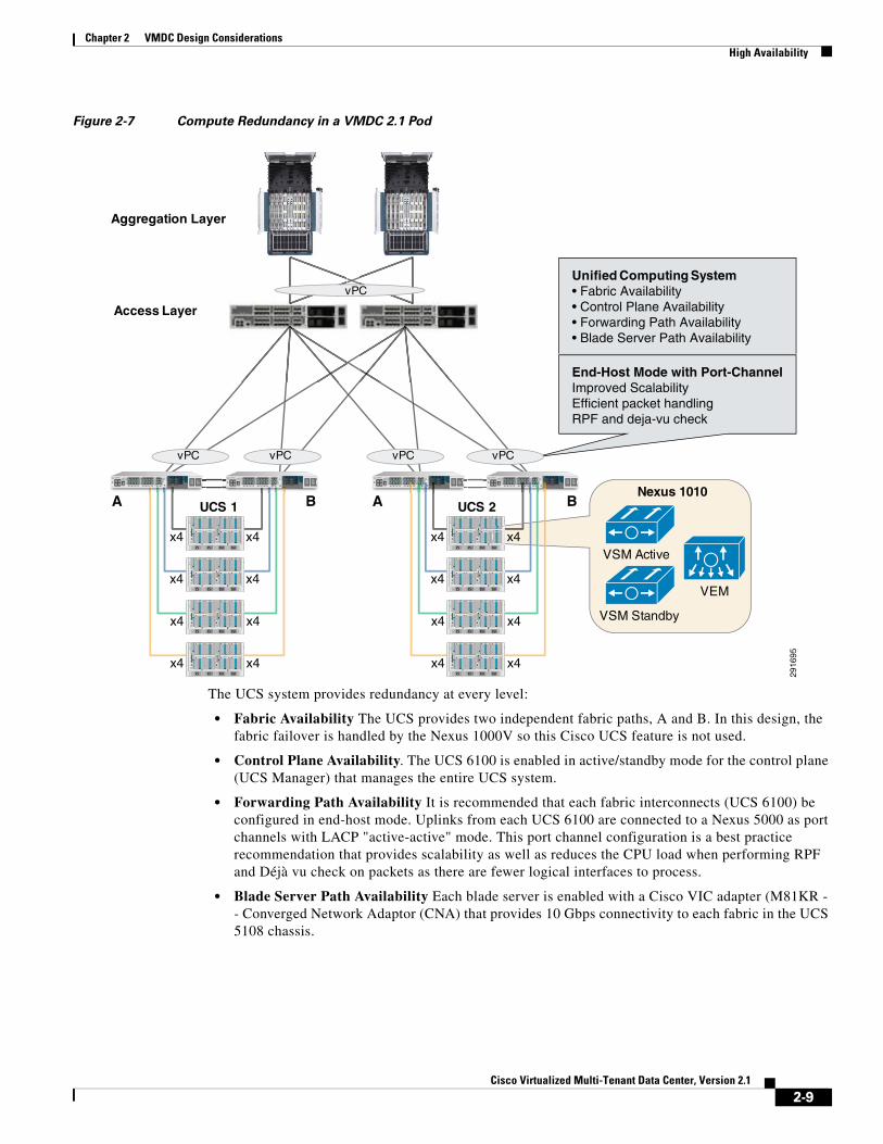
Compute AvailabilityThe Cisco VMDC 2.1 solution relies on the Cisco UCS at the compute layer. The availability of the Cisco UCS fabric is depicted in Figure 2-7.
2-8Cisco Virtualized Multi-Tenant Data Center, Version 2.1
Chapter 2 VMDC Design ConsiderationsHigh Availability
Figure 2-7 Compute Redundancy in a VMDC 2.1 Pod
The UCS system provides redundancy at every level:
• Fabric Availability The UCS provides two independent fabric paths, A and B. In this design, the fabric failover is handled by the Nexus 1000V so this Cisco UCS feature is not used.
• Control Plane Availability. The UCS 6100 is enabled in active/standby mode for the control plane (UCS Manager) that manages the entire UCS system.
• Forwarding Path Availability It is recommended that each fabric interconnects (UCS 6100) be configured in end-host mode. Uplinks from each UCS 6100 are connected to a Nexus 5000 as port channels with LACP "active-active" mode. This port channel configuration is a best practice recommendation that provides scalability as well as reduces the CPU load when performing RPF and Déjà vu check on packets as there are fewer logical interfaces to process.
• Blade Server Path Availability Each blade server is enabled with a Cisco VIC adapter (M81KR - - Converged Network Adaptor (CNA) that provides 10 Gbps connectivity to each fabric in the UCS 5108 chassis.
2916
95
Unified Computing System• Fabric Availability• Control Plane Availability• Forwarding Path Availability• Blade Server Path Availability
End-Host Mode with Port-ChannelImproved ScalabilityEfficient packet handlingRPF and deja-vu check
x4
x4
x4
x4
x4
x4
x4
x4
A AB BUCS 1
x4
x4
x4
x4
x4
x4
x4
x4
UCS 2
Aggregation Layer
VSM Active
VEM
Nexus 1010
VSM Standby
vPC
Access Layer
vPC vPC vPC vPC
2-9Cisco Virtualized Multi-Tenant Data Center, Version 2.1
Chapter 2 VMDC Design ConsiderationsVirtualized Multi-Tenancy
Storage AvailabilityIn the storage layer, the design is consistent with the high availability model implemented at other layers in the infrastructure, which include physical and path redundancy.
Virtualized Multi-TenancyTraditionally, a dedicated infrastructure would be deployed for each tenant that it hosted. This approach, while viable for a multi-tenant deployment model, does not scale well because of cost, complexity to manage, and inefficient use of resources. Deploying multiple tenants in a common infrastructure yields more efficient resource use and lower costs. However, each tenant may require path isolation for security and privacy from others sharing the common infrastructure. Therefore, logical separation or virtualization is a fundamental building block for multi-tenant environments. Virtualization at the various levels in the VMDC 2.1 architecture provides logical separation in the network, compute, and storage resources.
Flexible Tenant Model
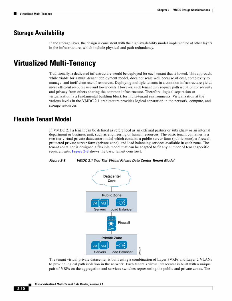
In VMDC 2.1 a tenant can be defined as referenced as an external partner or subsidiary or an internal department or business unit, such as engineering or human resources. The basic tenant container is a two tier virtual private datacenter model which contains a public server farm (public zone), a firewall protected private server farm (private zone), and load balancing services available in each zone. The tenant container is designed a flexible model that can be adapted to fit any number of tenant specific requirements. Figure 2-8 shows the basic tenant construct.
Figure 2-8 VMDC 2.1 Two Tier Virtual Private Data Center Tenant Model
The tenant virtual private datacenter is built using a combination of Layer 3VRFs and Layer 2 VLANs to provide logical path isolation in the network. Each tenant’s virtual datacenter is built with a unique pair of VRFs on the aggregation and services switches representing the public and private zones. The
2917
70
DatacenterCore
Public Zone
Servers Load Balancer
Private Zone
Servers Load Balancer
Firewall
VM VM
VM VM
2-10Cisco Virtualized Multi-Tenant Data Center, Version 2.1
Chapter 2 VMDC Design ConsiderationsVirtualized Multi-Tenancy
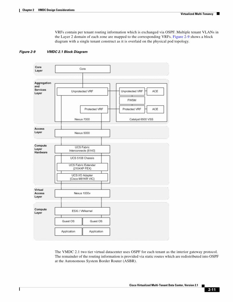
VRFs contain per tenant routing information which is exchanged via OSPF. Multiple tenant VLANs in the Layer 2 domain of each zone are mapped to the corresponding VRFs. Figure 2-9 shows a block diagram with a single tenant construct as it is overlaid on the physical pod topology.
Figure 2-9 VMDC 2.1 Block Diagram
The VMDC 2.1 two tier virtual datacenter uses OSPF for each tenant as the interior gateway protocol. The remainder of the routing information is provided via static routes which are redistributed into OSPF at the Autonomous System Border Router (ASBR).
2-11Cisco Virtualized Multi-Tenant Data Center, Version 2.1
Chapter 2 VMDC Design ConsiderationsVirtualized Multi-Tenancy
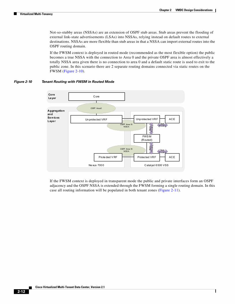
Not-so-stubby areas (NSSAs) are an extension of OSPF stub areas. Stub areas prevent the flooding of external link-state advertisements (LSAs) into NSSAs, relying instead on default routes to external destinations. NSSAs are more flexible than stub areas in that a NSSA can import external routes into the OSPF routing domain.
If the FWSM context is deployed in routed mode (recommended as the most flexible option) the public becomes a true NSSA with the connection to Area 0 and the private OSPF area is almost effectively a totally NSSA area given there is no connection to area 0 and a default static route is used to exit to the public zone. In this scenario there are 2 separate routing domains connected via static routes on the FWSM (Figure 2-10).
Figure 2-10 Tenant Routing with FWSM in Routed Mode
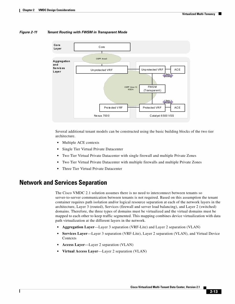
If the FWSM context is deployed in transparent mode the public and private interfaces form an OSPF adjacency and the OSPF NSSA is extended through the FWSM forming a single routing domain. In this case all routing information will be populated in both tenant zones (Figure 2-11).
Catalyst 6 500 VSSNe xus 700 0
CoreCoreLayer
AggregationandSe rv ic esLaye r
FWS M(Routed)
OSPF Area 0
OSPF Area 10NSSA
OSPF Area 10NSSA
Protected VRFPro te cted V RF
Un protected VRF Unp rotected VRF
Sta
tic
Ro
utin
g
ACE
ACE
StaticRouting
Sta
tic
Ro
utin
g
StaticRouting
2-12Cisco Virtualized Multi-Tenant Data Center, Version 2.1
Chapter 2 VMDC Design ConsiderationsVirtualized Multi-Tenancy
Figure 2-11 Tenant Routing with FWSM in Transparent Mode
Several additional tenant models can be constructed using the basic building blocks of the two tier architecture.
• Multiple ACE contexts
• Single Tier Virtual Private Datacenter
• Two Tier Virtual Private Datacenter with single firewall and multiple Private Zones
• Two Tier Virtual Private Datacenter with multiple firewalls and multiple Private Zones
• Three Tier Virtual Private Datacenter
Network and Services SeparationThe Cisco VMDC 2.1 solution assumes there is no need to interconnect between tenants so server-to-server communication between tenants is not required. Based on this assumption the tenant container requires path isolation and/or logical resource separation at each of the network layers in the architecture, Layer 3 (routed), Services (firewall and server load balancing), and Layer 2 (switched) domains. Therefore, the three types of domains must be virtualized and the virtual domains must be mapped to each other to keep traffic segmented. This mapping combines device virtualization with data path virtualization at the different layers in the network.
• Aggregation Layer—Layer 3 separation (VRF-Lite) and Layer 2 separation (VLAN)
• Services Layer—Layer 3 separation (VRF-Lite), Layer 2 separation (VLAN), and Virtual Device Contexts
• Access Layer—Layer 2 separation (VLAN)
• Virtual Access Layer—Layer 2 separation (VLAN)
Catalyst 6 500 VSSNe xus 700 0
CoreCoreLayer
AggregationandSe rv ic esLaye r
OSPF Area 0
OSPF Area 10NSSA
Pro te cted V RF
Un protected VRF Unp rotected VRF ACE
ACE
StaticRouting
StaticRouting
FWS M (Transparent )
Protected VRF
2-13Cisco Virtualized Multi-Tenant Data Center, Version 2.1
Chapter 2 VMDC Design ConsiderationsVirtualized Multi-Tenancy
Compute SeparationVirtualization in the compute layer introduces new challenges and concerns. A physical host now contains multiple logical servers (Vitual Machines) requiring some number of policies to be applied at the VM level. Also, new technologies, such as vMotion, introduced VM mobility within a cluster, where policies follow VMs as they are moved across switch ports and between hypervisor hosts.
To provide traffic isolation for virtual machines, the VMDC solution emphasizes the following techniques:
• Port Profiles Port profiles enable VLAN-based separation. Using features found in the Nexus 1000V, you create port profiles and apply them to virtual machine NICs via the VMware vCenter. Each port profile is a policy that can be applied to the VM. The policy settings include VLAN, uplink pinning, security, and policy information.
• Virtual Adapters Cisco UCS M81KR Virtual Interface Card (VIC) is a network interface consolidation solution. Traditionally, each VMware ESX server has multiple LAN and SAN interfaces to separate vMotion, service console, NFS, backup, and VM data. In this model, the ESXi host requires 10 adapters. Using the Cisco VIC, distinct virtual adapters are created for each traffic flow type using a single, two-port adapter.
• VLAN Separation Using the Cisco VIC features, you can create virtual adapters and map them to unique virtual machines and VMkernal interfaces through the hypervisor. In a multi-tenant scenario where distinct tenants reside on the same physical server and transmit their data over a shared physical interface, the infrastructure cannot isolate the tenant production data. However, Cisco VIC combined with VN-Link technology can isolate this data via VLAN-based separation. VLAN separation is accomplished when virtual adapters (up to 128) are mapped to specific virtual machines and VMkernal interfaces.
Storage SeparationTo extend secure separation to the storage layer, VMDC 2.1 uses isolation mechanisms available in either SAN or NAS environments. Tenant separation can extend through the switches and into the storage arrays.
Storage Area Network (SAN)
The VMDC 2.1 architecture was validated using the Cisco MDS 9513 and EMC VMAX for Block Storage. This allows for Fiber Channel (FC) access separation at the switch port level (VSAN), logical path access separation via IVR, path level separation using WWN/Device Hard Zoning, and at the virtual media level inside the Storage Array (LUN Masking and Mapping).
Network Attached Storage (NAS)
The VMDC 2.1 architecture was validated using NetApp for NFS storage, which enables virtualized storage space such that each tenant (application or user) can be separated with use of IP spaces and VLANs mapped to network layer separation.
2-14Cisco Virtualized Multi-Tenant Data Center, Version 2.1
Chapter 2 VMDC Design ConsiderationsPerformance and Scalability
Performance and ScalabilityPerformance is a measure of the speed at which a system works. Scalability is the ability to grow in size or complexity without showing negative effects. Problems in either area may expose the enterprise to operating inefficiencies and potential failures of critical business components. Testing, monitoring, and tuning the environment ensures optimal performance and user satisfaction.
There are multiple dimensions that form overall datacenter scalability, including physical capacity, logical capacity, topology, and functionality. All of these aspects combined drive the overall data center footprint. The following list illustrates some key variables that contribute to the scaling and performance design considerations in a given datacenter:
• Pods
• Port Density
• Access switches
• Access ports
• Port channels
• vPCs
• VLANs
• MAC addresses
• STP logical ports
• Interfaces
• Routing adjacencies
• HSRP groups
• Routes
• Multicast routes
• CPUs
• Memory
• Oversubscription Ratios
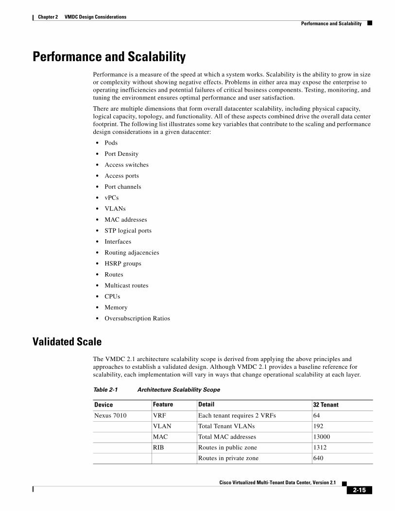
Validated ScaleThe VMDC 2.1 architecture scalability scope is derived from applying the above principles and approaches to establish a validated design. Although VMDC 2.1 provides a baseline reference for scalability, each implementation will vary in ways that change operational scalability at each layer.
Table 2-1 Architecture Scalability Scope
Device Feature Detail 32 Tenant
Nexus 7010 VRF Each tenant requires 2 VRFs 64
VLAN Total Tenant VLANs 192
MAC Total MAC addresses 13000
RIB Routes in public zone 1312
Routes in private zone 640
2-15Cisco Virtualized Multi-Tenant Data Center, Version 2.1
Chapter 2 VMDC Design ConsiderationsPerformance and Scalability
OSPF AFI 64
Neighbor adjacencies in public zone 128
Neighbor adjacencies in private zone 64
Multicast PIM adjacencies public zone only 24
Total mroutes public zone only 128
Total number of (*,G) routes public zone only
64
Total number of (S,G) routes public zone only
64
Catalyst 6509 VRFs Each tenant requires 2 VRFs 64
VLAN 2 ACE VLANs / 2 FWSM VLANs 128
RIB Routes in public zone 832
Routes in private zone 416
OSPF Processes 64
Neighbor adjacencies 128
ACE Context 2 ACE contexts per Tenant 64
VIPs 4 VIPs per ACE context 32T 128
FWSM Context 1 FW context per tenant 32
Nexus 5020 VLANs 3 Server VLANs per VRF 192
Management VLANs 8
NFS vFiler VLANs 32
MAC Total MAC addresses 13000
Nexus 61xx VLANs 3 Server VLANs per VRF 192
Management 8
NFS vFiler VLANs 32
MAC Total MAC addresses 13000
Nexus 1000v VLANs 3 Server VLANs per VRF 192
Management 8
NFS vFiler VLANs 32
MAC Total MAC addresses 13000
UCS VM Test VMs 128
VMs per blade server ratio 4:1
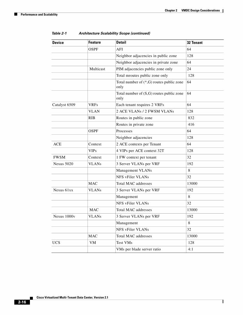
Table 2-1 Architecture Scalability Scope (continued)
Device Feature Detail 32 Tenant
2-16Cisco Virtualized Multi-Tenant Data Center, Version 2.1
Chapter 2 VMDC Design ConsiderationsPerformance and Scalability
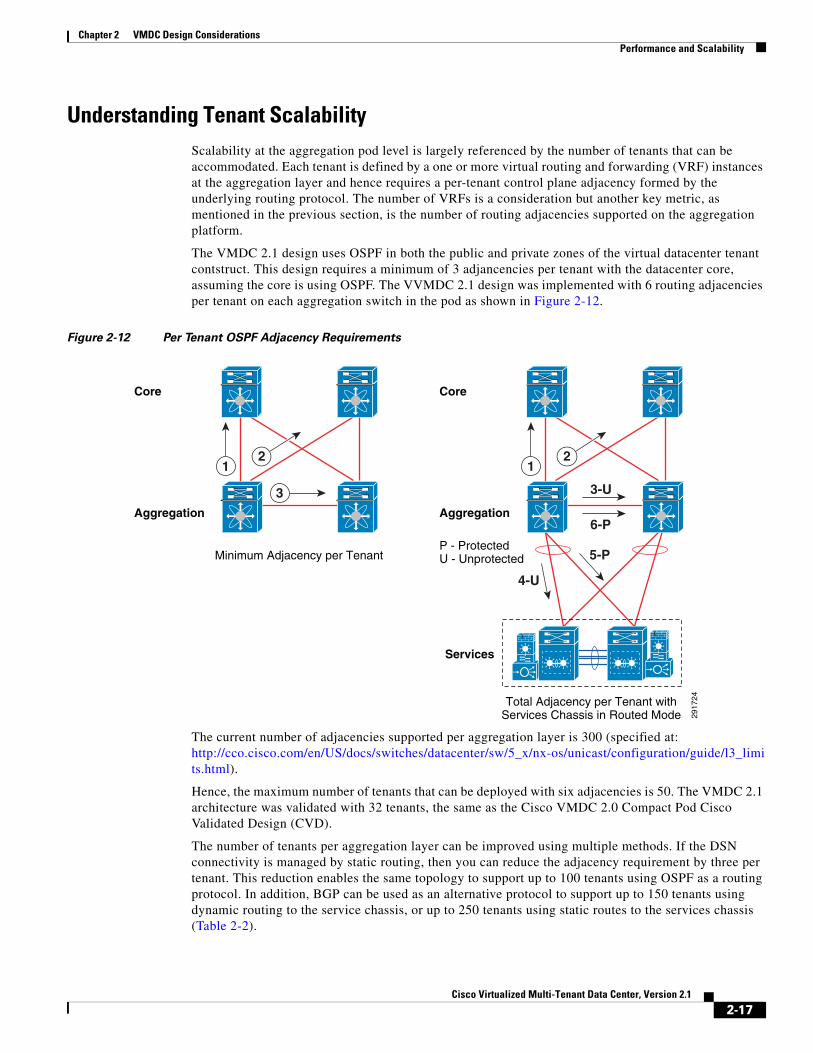
Understanding Tenant ScalabilityScalability at the aggregation pod level is largely referenced by the number of tenants that can be accommodated. Each tenant is defined by a one or more virtual routing and forwarding (VRF) instances at the aggregation layer and hence requires a per-tenant control plane adjacency formed by the underlying routing protocol. The number of VRFs is a consideration but another key metric, as mentioned in the previous section, is the number of routing adjacencies supported on the aggregation platform.
The VMDC 2.1 design uses OSPF in both the public and private zones of the virtual datacenter tenant contstruct. This design requires a minimum of 3 adjancencies per tenant with the datacenter core, assuming the core is using OSPF. The VVMDC 2.1 design was implemented with 6 routing adjacencies per tenant on each aggregation switch in the pod as shown in Figure 2-12.
Figure 2-12 Per Tenant OSPF Adjacency Requirements
The current number of adjacencies supported per aggregation layer is 300 (specified at: http://cco.cisco.com/en/US/docs/switches/datacenter/sw/5_x/nx-os/unicast/configuration/guide/l3_limits.html).
Hence, the maximum number of tenants that can be deployed with six adjacencies is 50. The VMDC 2.1 architecture was validated with 32 tenants, the same as the Cisco VMDC 2.0 Compact Pod Cisco Validated Design (CVD).
The number of tenants per aggregation layer can be improved using multiple methods. If the DSN connectivity is managed by static routing, then you can reduce the adjacency requirement by three per tenant. This reduction enables the same topology to support up to 100 tenants using OSPF as a routing protocol. In addition, BGP can be used as an alternative protocol to support up to 150 tenants using dynamic routing to the service chassis, or up to 250 tenants using static routes to the services chassis (Table 2-2).
Services
Minimum Adjacency per TenantP - ProtectedU - Unprotected
Total Adjacency per Tenant withServices Chassis in Routed Mode 29
1724
Core
Aggregation
3
21
Core
Aggregation
3-U
4-U
6-P
5-P
21
2-17Cisco Virtualized Multi-Tenant Data Center, Version 2.1
Chapter 2 VMDC Design ConsiderationsPerformance and Scalability
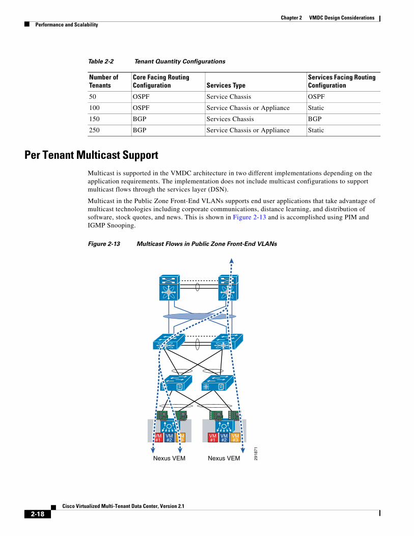
Per Tenant Multicast SupportMulticast is supported in the VMDC architecture in two different implementations depending on the application requirements. The implementation does not include multicast configurations to support multicast flows through the services layer (DSN).
Multicast in the Public Zone Front-End VLANs supports end user applications that take advantage of multicast technologies including corporate communications, distance learning, and distribution of software, stock quotes, and news. This is shown in Figure 2-13 and is accomplished using PIM and IGMP Snooping.
Figure 2-13 Multicast Flows in Public Zone Front-End VLANs
Table 2-2 Tenant Quantity Configurations
Number of Tenants
Core Facing Routing Configuration Services Type
Services Facing Routing Configuration
50 OSPF Service Chassis OSPF
100 OSPF Service Chassis or Appliance Static
150 BGP Services Chassis BGP
250 BGP Service Chassis or Appliance Static
Nexus VEM Nexus VEM 2918
71
VM#1
VM#2
VM#3
VM#1
VM#2
VM#3
2-18Cisco Virtualized Multi-Tenant Data Center, Version 2.1
Chapter 2 VMDC Design ConsiderationsPerformance and Scalability
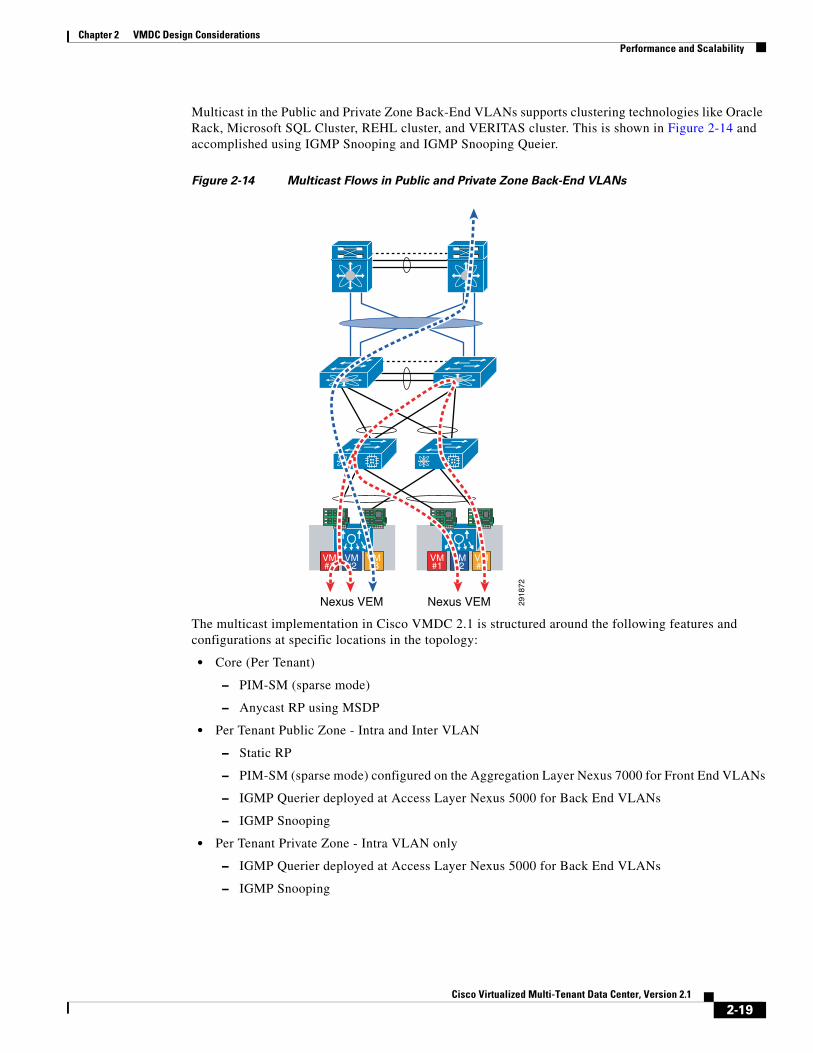
Multicast in the Public and Private Zone Back-End VLANs supports clustering technologies like Oracle Rack, Microsoft SQL Cluster, REHL cluster, and VERITAS cluster. This is shown in Figure 2-14 and accomplished using IGMP Snooping and IGMP Snooping Queier.
Figure 2-14 Multicast Flows in Public and Private Zone Back-End VLANs
The multicast implementation in Cisco VMDC 2.1 is structured around the following features and configurations at specific locations in the topology:
• Core (Per Tenant)
– PIM-SM (sparse mode)
– Anycast RP using MSDP
• Per Tenant Public Zone - Intra and Inter VLAN
– Static RP
– PIM-SM (sparse mode) configured on the Aggregation Layer Nexus 7000 for Front End VLANs
– IGMP Querier deployed at Access Layer Nexus 5000 for Back End VLANs
– IGMP Snooping
• Per Tenant Private Zone - Intra VLAN only
– IGMP Querier deployed at Access Layer Nexus 5000 for Back End VLANs
– IGMP Snooping
Nexus VEM Nexus VEM 2918
72
VM#1
VM#2
VM#3
VM#1
VM#2
VM#3
2-19Cisco Virtualized Multi-Tenant Data Center, Version 2.1
Chapter 2 VMDC Design ConsiderationsPerformance and Scalability
Anycast RP for PIM-SM
The RP is a critical function for PIM-SM deployments. RP redundancy is always recommended. The best form of redundancy for PIM-SM is Anycast RP which is described in the document:
Anycast RP: http://www.cisco.com/en/US/docs/ios/solutions_docs/ip_multicast/White_papers/anycast.html
VMDC 2.1 does not specify an RP redundancy design or specific RP location, the assumption is that the RP would be either at the core layer, somewhere else within the datacenter, or further out on the enterprise network. The reference of Anycast RP is for example purposes only as this is a typical method for ensuring RP reachability.
PIM Sparse Mode (PIM-SM)
PIM-SM uses a pull model to deliver multicast traffic. Only network segments with active receivers that have explicitly requested the data will receive the traffic.
PIM-SM distributes information about active sources by forwarding data packets on the shared tree. Because PIM-SM uses shared trees (at least, initially), it requires the use of a rendezvous point (RP). The RP must be administratively configured for each tenant requiring multicast support. For each tenant public zone (VRF) in the system, independent multicast system resources are maintained, including the MRIB.
IGMP Snooping
Every Cisco switch in the VMDC 2.1 solution supports IGMP snooping. IGMP snooping should always be enabled if you are running IP Multicast. Some platform and switch software combinations may not have IGMP snooping enabled by default. Make sure IGMP snooping is enabled before running any multicast streams.
IGMP snooping is an IP Multicast constraining mechanism that runs on a Layer 2 LAN switch. Without IGMP snooping enabled, all multicast traffic will be forwarded to all hosts connected to the switch. IGMP snooping will insure that only hosts that are interested in the data stream will receive it.
The Back End VLANs in both the public and private zones run multicast in a contained environment and not have it forwarded to the rest of the network. On these VLANs, PIM is not enabled on the routers so there is no IGMP querier elected.
IGMP Snooping Querier
For Back-End VLANs where PIM is not enabled on an interface because the multicast traffic does not need to be routed, you must configure an IGMP snooping querier to send membership queries. You define the querier in a VLAN that contains multicast sources and receivers but no other active querier.
When an IGMP snooping querier is enabled, it sends out periodic IGMP queries that trigger IGMP report messages from hosts that want to receive IP multicast traffic. IGMP snooping listens to these IGMP reports to establish appropriate forwarding.
For additional multicast information see the following links:
IP Multicast Best Practices
http://www.cisco.com/en/US/prod/collateral/iosswrel/ps6537/ps6552/ps6592/whitepaper_c11-474791.html
2-20Cisco Virtualized Multi-Tenant Data Center, Version 2.1
Chapter 2 VMDC Design ConsiderationsPerformance and Scalability
IP Multicast White Papers
http://www.cisco.com/en/US/products/ps6552/prod_white_papers_list.html
Jumbo Frame SupportIt has been shown that a server can boost its performance and reduce its CPU utilization significantly by using jumbo frames during data transfers. For example, during the tests a server configured with two GbE NICs was shown to have increased its network throughput and decreased its CPU utilization by 44% when using 9 KB frames instead of standard 1518-byte frames.
This type of performance improvement is only possible when long data transfers are performed; for example, in applications such as:
• Server to Server communication (e.g., NFS transactions, vMotion, etc.)
• Server clustering
• High-speed data backups
In these scenarios jumbo frames are becoming a standard for high-speed transfers over the Ethernet medium.
A jumbo frame is basically anything bigger than 1522 bytes, with a common size of 9000 bytes, which is exactly six times the size of a standard Ethernet frame. With Ethernet headers, a 9k byte jumbo frame would be 9014-9022 bytes. This makes it large enough to encapsulate a standard NFS (network file system) data block of 8192 bytes, yet not large enough to exceed the 12,000 byte limit of Ethernet's error checking CRC (cyclic redundancy check) algorithm.
When designing for jumbo MTU services, consider the following factors:
• Understand jumbo frames are not a standard, so testing prior to implementation is critical
• Jumbos must be supported end to end for any application benefit
• Do not use anything above the common size of 9000 bytes
• Transit links can be configured with higher values to allow for any additional header overhead
• If available, use TCP Offload Engines with Jumbo Frames on server based NICs
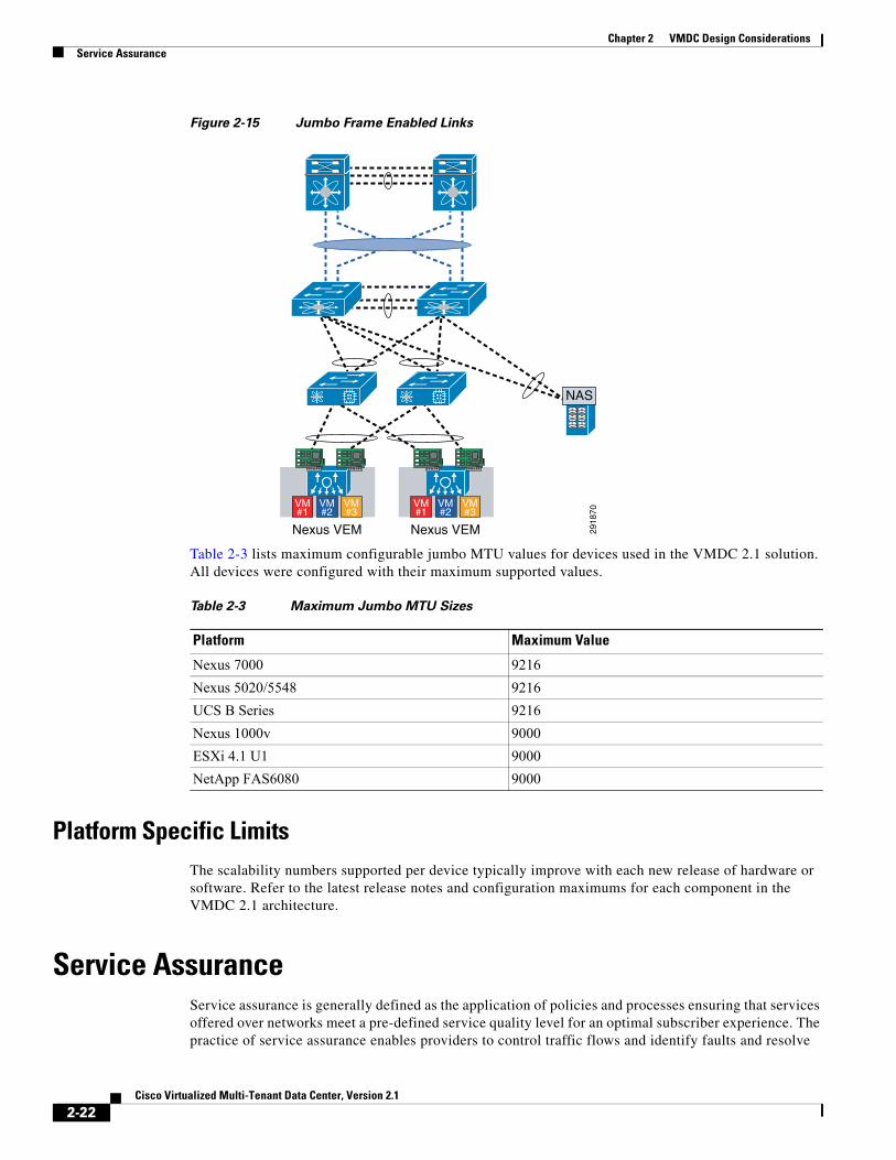
In the VMDC 2.1 design, all paths below the Nexus 7000 were all enabled for jumbo frames. The full front end paths, to the services chassis and exiting the aggregation towards the core, campus, or WAN, were not enabled but could be accommodated with additional configuration. The links are illustrated in Figure 2-15.
2-21Cisco Virtualized Multi-Tenant Data Center, Version 2.1
Chapter 2 VMDC Design ConsiderationsService Assurance
Figure 2-15 Jumbo Frame Enabled Links
Table 2-3 lists maximum configurable jumbo MTU values for devices used in the VMDC 2.1 solution. All devices were configured with their maximum supported values.
Platform Specific LimitsThe scalability numbers supported per device typically improve with each new release of hardware or software. Refer to the latest release notes and configuration maximums for each component in the VMDC 2.1 architecture.
Service AssuranceService assurance is generally defined as the application of policies and processes ensuring that services offered over networks meet a pre-defined service quality level for an optimal subscriber experience. The practice of service assurance enables providers to control traffic flows and identify faults and resolve
Nexus VEM Nexus VEM 2918
70
VM#1
VM#2
VM#3
NAS
VM#1
VM#2
VM#3
Table 2-3 Maximum Jumbo MTU Sizes
Platform Maximum Value
Nexus 7000 9216
Nexus 5020/5548 9216
UCS B Series 9216
Nexus 1000v 9000
ESXi 4.1 U1 9000
NetApp FAS6080 9000
2-22Cisco Virtualized Multi-Tenant Data Center, Version 2.1
Chapter 2 VMDC Design ConsiderationsService Assurance
those issues in a timely manner so as to minimize service downtime. The practice also includes policies and processes to proactively diagnose and resolve service quality degradations or device malfunctions before subscribers are impacted.
In VMDC 2.1 network service assurance encompasses the following concepts:
• Traffic Engineering
• Quality of Service (QoS) framework
• Network Analysis
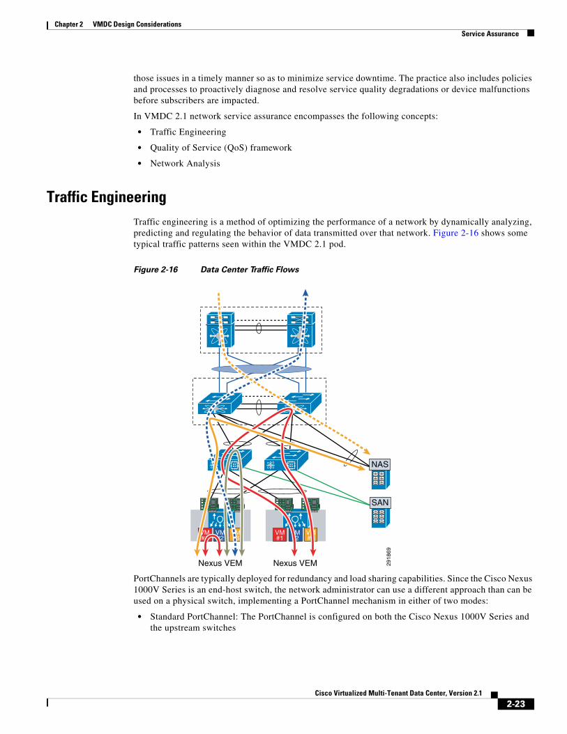
Traffic EngineeringTraffic engineering is a method of optimizing the performance of a network by dynamically analyzing, predicting and regulating the behavior of data transmitted over that network. Figure 2-16 shows some typical traffic patterns seen within the VMDC 2.1 pod.
Figure 2-16 Data Center Traffic Flows
PortChannels are typically deployed for redundancy and load sharing capabilities. Since the Cisco Nexus 1000V Series is an end-host switch, the network administrator can use a different approach than can be used on a physical switch, implementing a PortChannel mechanism in either of two modes:
• Standard PortChannel: The PortChannel is configured on both the Cisco Nexus 1000V Series and the upstream switches
Nexus VEM Nexus VEM 2918
69
SAN
VM#1
VM#2
VM#3
NAS
VM#1
VM#2
VM#3
2-23Cisco Virtualized Multi-Tenant Data Center, Version 2.1
Chapter 2 VMDC Design ConsiderationsService Assurance
• Special PortChannel: The PortChannel is configured only on the Cisco Nexus 1000V Series, with no need to configure anything upstream. There are two options available here, MAC Pinning and vPC Host Mode.
Regardless of the mode, PortChannels are managed using the standard PortChannel CLI construct, but each mode behaves differently.
For more information on the Nexus 1000v Port-Channel configurations follow this link:
http://www.cisco.com/en/US/prod/collateral/switches/ps9441/ps9902/guide_c07-556626.html#wp9000299
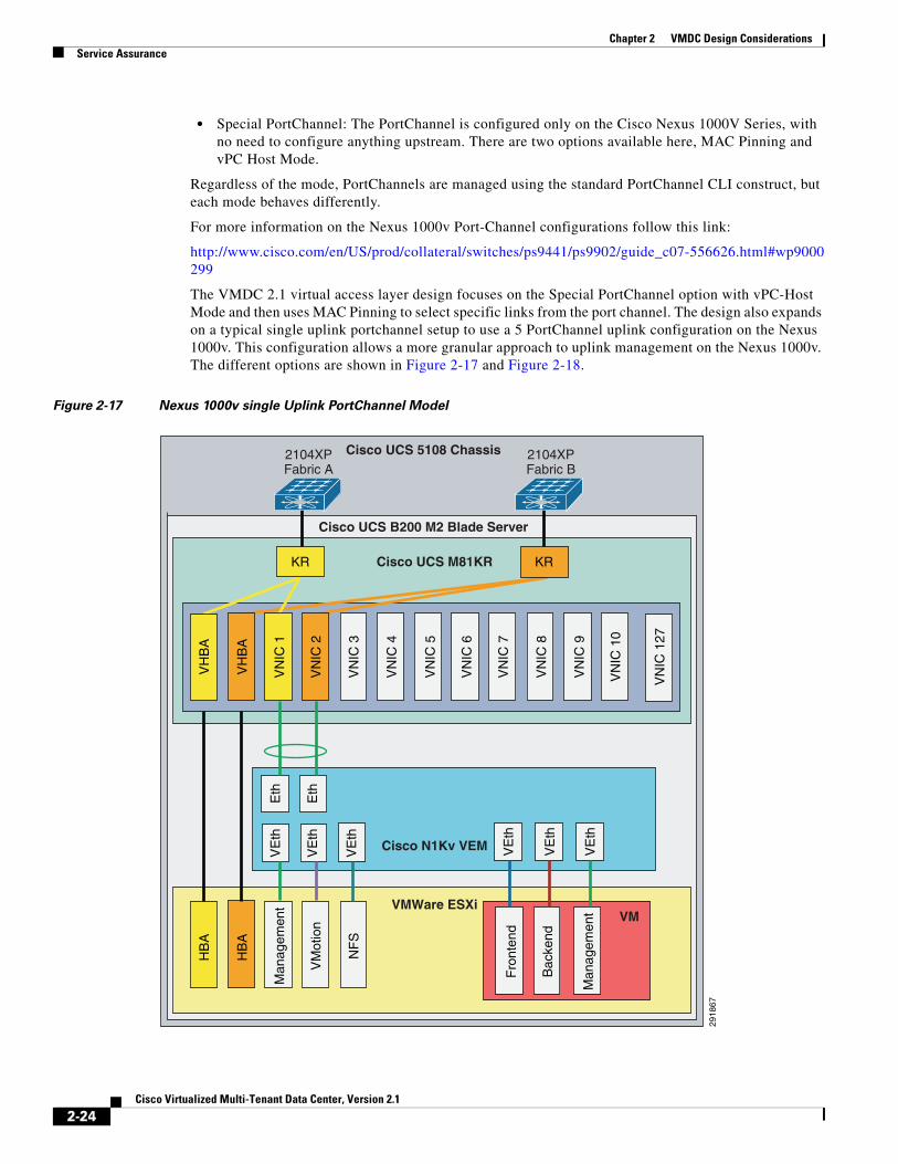
The VMDC 2.1 virtual access layer design focuses on the Special PortChannel option with vPC-Host Mode and then uses MAC Pinning to select specific links from the port channel. The design also expands on a typical single uplink portchannel setup to use a 5 PortChannel uplink configuration on the Nexus 1000v. This configuration allows a more granular approach to uplink management on the Nexus 1000v. The different options are shown in Figure 2-17 and Figure 2-18.
Figure 2-17 Nexus 1000v single Uplink PortChannel Model
2918
67
VN
IC 1
27
VN
IC 1
0
VN
IC 9
VN
IC 8
VN
IC 7
VN
IC 6
VN
IC 5
VN
IC 4
VN
IC 3
VN
IC 2
VN
IC 1
NF
S
VM
otio
n
Man
agem
ent
Man
agem
ent
Bac
kend
Fro
nten
d
VH
BA
VH
BA
HB
A
HB
A
Eth
Eth
VE
th
VE
th
VE
th
VE
th
VE
th
VE
th
Cisco UCS M81KR
Cisco UCS B200 M2 Blade Server
Cisco UCS 5108 Chassis2104XPFabric A
2104XPFabric B
Cisco N1Kv VEM
VMWare ESXiVM
KR KR
2-24Cisco Virtualized Multi-Tenant Data Center, Version 2.1
Chapter 2 VMDC Design ConsiderationsService Assurance
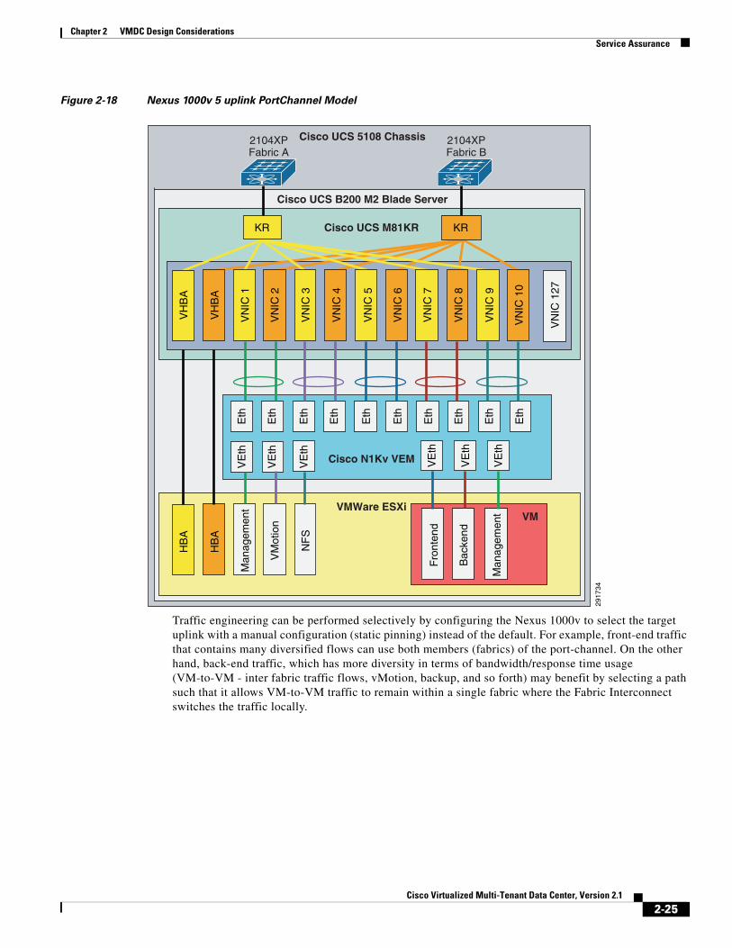
Figure 2-18 Nexus 1000v 5 uplink PortChannel Model
Traffic engineering can be performed selectively by configuring the Nexus 1000v to select the target uplink with a manual configuration (static pinning) instead of the default. For example, front-end traffic that contains many diversified flows can use both members (fabrics) of the port-channel. On the other hand, back-end traffic, which has more diversity in terms of bandwidth/response time usage (VM-to-VM - inter fabric traffic flows, vMotion, backup, and so forth) may benefit by selecting a path such that it allows VM-to-VM traffic to remain within a single fabric where the Fabric Interconnect switches the traffic locally.
2917
34
VN
IC 1
27
VN
IC 1
0
VN
IC 9
VN
IC 8
VN
IC 7
VN
IC 6
VN
IC 5
VN
IC 4
VN
IC 3
VN
IC 2
VN
IC 1
NF
S
VM
otio
n
Man
agem
ent
Man
agem
ent
Bac
kend
Fro
nten
d
VH
BA
VH
BA
HB
A
HB
A
Eth
Eth
Eth
Eth
Eth
Eth
Eth
Eth
Eth
VE
th
VE
th
VE
th
VE
th
VE
th
VE
th
Eth
Cisco UCS M81KR
Cisco UCS B200 M2 Blade Server
Cisco UCS 5108 Chassis2104XPFabric A
2104XPFabric B
Cisco N1Kv VEM
VMWare ESXiVM
KR KR
2-25Cisco Virtualized Multi-Tenant Data Center, Version 2.1
Chapter 2 VMDC Design ConsiderationsService Assurance
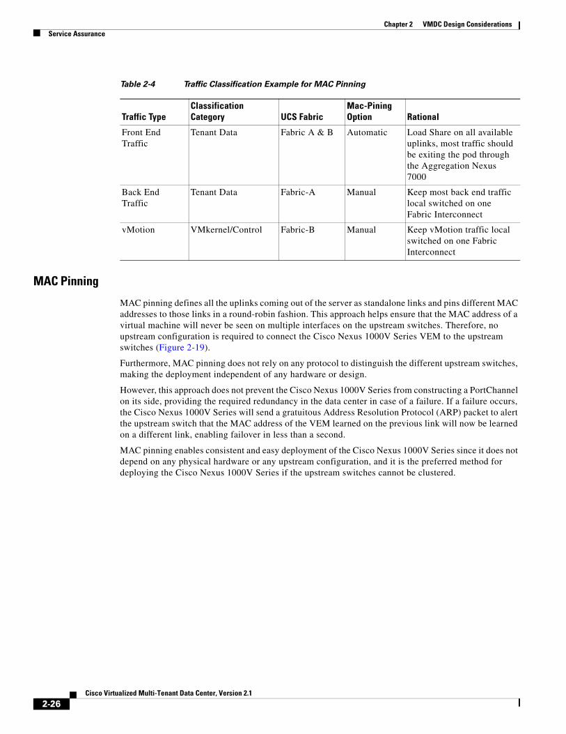
MAC Pinning
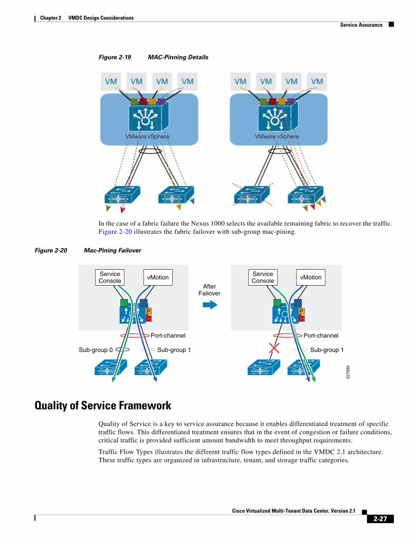
MAC pinning defines all the uplinks coming out of the server as standalone links and pins different MAC addresses to those links in a round-robin fashion. This approach helps ensure that the MAC address of a virtual machine will never be seen on multiple interfaces on the upstream switches. Therefore, no upstream configuration is required to connect the Cisco Nexus 1000V Series VEM to the upstream switches (Figure 2-19).
Furthermore, MAC pinning does not rely on any protocol to distinguish the different upstream switches, making the deployment independent of any hardware or design.
However, this approach does not prevent the Cisco Nexus 1000V Series from constructing a PortChannel on its side, providing the required redundancy in the data center in case of a failure. If a failure occurs, the Cisco Nexus 1000V Series will send a gratuitous Address Resolution Protocol (ARP) packet to alert the upstream switch that the MAC address of the VEM learned on the previous link will now be learned on a different link, enabling failover in less than a second.
MAC pinning enables consistent and easy deployment of the Cisco Nexus 1000V Series since it does not depend on any physical hardware or any upstream configuration, and it is the preferred method for deploying the Cisco Nexus 1000V Series if the upstream switches cannot be clustered.
Table 2-4 Traffic Classification Example for MAC Pinning
Traffic TypeClassification Category UCS Fabric
Mac-Pining Option Rational
Front End Traffic
Tenant Data Fabric A & B Automatic Load Share on all available uplinks, most traffic should be exiting the pod through the Aggregation Nexus 7000
Back End Traffic
Tenant Data Fabric-A Manual Keep most back end traffic local switched on one Fabric Interconnect
vMotion VMkernel/Control Fabric-B Manual Keep vMotion traffic local switched on one Fabric Interconnect
2-26Cisco Virtualized Multi-Tenant Data Center, Version 2.1
Chapter 2 VMDC Design ConsiderationsService Assurance
Figure 2-19 MAC-Pinning Details
In the case of a fabric failure the Nexus 1000 selects the available remaining fabric to recover the traffic. Figure 2-20 illustrates the fabric failover with sub-group mac-pining.
Figure 2-20 Mac-Pining Failover
Quality of Service FrameworkQuality of Service is a key to service assurance because it enables differentiated treatment of specific traffic flows. This differentiated treatment ensures that in the event of congestion or failure conditions, critical traffic is provided sufficient amount bandwidth to meet throughput requirements.
Traffic Flow Types illustrates the different traffic flow types defined in the VMDC 2.1 architecture. These traffic types are organized in infrastructure, tenant, and storage traffic categories.
Port-channel
Sub-group 1Sub-group 0
AfterFailover
2279
92
PC
ServiceConsole vMotion
Port-channel
Sub-group 1
PC
ServiceConsole vMotion
2-27Cisco Virtualized Multi-Tenant Data Center, Version 2.1
Chapter 2 VMDC Design ConsiderationsService Assurance
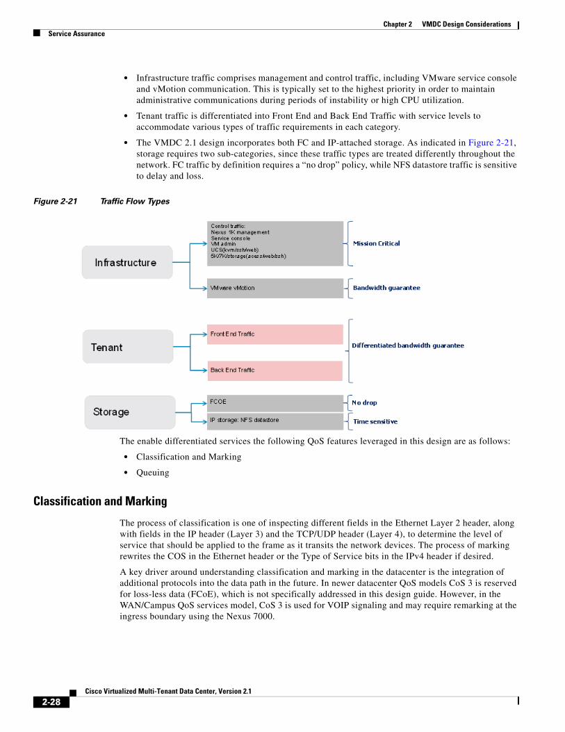
• Infrastructure traffic comprises management and control traffic, including VMware service console and vMotion communication. This is typically set to the highest priority in order to maintain administrative communications during periods of instability or high CPU utilization.
• Tenant traffic is differentiated into Front End and Back End Traffic with service levels to accommodate various types of traffic requirements in each category.
• The VMDC 2.1 design incorporates both FC and IP-attached storage. As indicated in Figure 2-21, storage requires two sub-categories, since these traffic types are treated differently throughout the network. FC traffic by definition requires a “no drop” policy, while NFS datastore traffic is sensitive to delay and loss.
Figure 2-21 Traffic Flow Types
The enable differentiated services the following QoS features leveraged in this design are as follows:
• Classification and Marking
• Queuing
Classification and Marking
The process of classification is one of inspecting different fields in the Ethernet Layer 2 header, along with fields in the IP header (Layer 3) and the TCP/UDP header (Layer 4), to determine the level of service that should be applied to the frame as it transits the network devices. The process of marking rewrites the COS in the Ethernet header or the Type of Service bits in the IPv4 header if desired.
A key driver around understanding classification and marking in the datacenter is the integration of additional protocols into the data path in the future. In newer datacenter QoS models CoS 3 is reserved for loss-less data (FCoE), which is not specifically addressed in this design guide. However, in the WAN/Campus QoS services model, CoS 3 is used for VOIP signaling and may require remarking at the ingress boundary using the Nexus 7000.
2-28Cisco Virtualized Multi-Tenant Data Center, Version 2.1
Chapter 2 VMDC Design ConsiderationsService Assurance
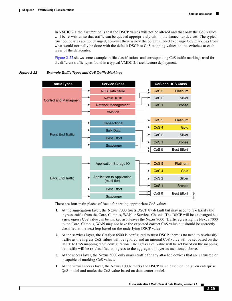
In VMDC 2.1 the assumption is that the DSCP values will not be altered and that only the CoS values will be re-written so that traffic can be queued appropriately within the datacenter devices. The typical trust boundaries are not changed, however there is now the potential need to change CoS markings from what would normally be done with the default DSCP to CoS mapping values on the switches at each layer of the datacenter.
Figure 2-22 shows some example traffic classifications and corresponding CoS traffic markings used for the different traffic types found in a typical VMDC 2.1 architecture deployment.
Figure 2-22 Example Traffic Types and CoS Traffic Markings
There are four main places of focus for setting appropriate CoS values:
1. At the aggregation layer, the Nexus 7000 trusts DSCP by default but may need to re-classify the ingress traffic from the Core, Campus, WAN or Services Chassis. The DSCP will be unchanged but a new egress CoS value can be marked as it leaves the Nexus 7000. Traffic egressing the Nexus 7000 to the Core, Campus, WAN may not have the expected correct CoS value but should be correctly classified at the next hop based on the underlying DSCP value.
2. At the services layer, the Catalyst 6500 is configured to trust DSCP, there is no need to re-classify traffic as the ingress CoS values will be ignored and an internal CoS value will be set based on the DSCP to CoS mapping table configuration. The egress CoS value will be set based on the mapping but traffic will be re-classified at ingress to the aggregation layer as mentioned above.
3. At the access layer, the Nexus 5000 only marks traffic for any attached devices that are untrusted or incapable of marking CoS values.
4. At the virtual access layer, the Nexus 1000v marks the DSCP value based on the given enterprise QoS model and marks the CoS value based on data center model.
Back End Traffic
Traffic Types
Bulk Data
Application Storage IO
Front End Traffic
vMotion
Application to Application(multi-tier)
Best Effort
Scavenger
Service-Class
Control and Managment
CoS 4
CoS 1
CoS 1
CoS 4
CoS 2
CoS 1
CoS and UCS Class
CoS 5
CoS 5
CoS 2
CoS 0
CoS 2
CoS 5NFS Data Store
Nexus 1010
Network Management
Transactional
Best Effort
ScavengerCoS 0
Gold
Bronze
Bronze
Gold
Silver
Bronze
Platinum
Platinum
Silver
Best Effort
Silver
Platinum
Best Effort
2917
13
2-29Cisco Virtualized Multi-Tenant Data Center, Version 2.1
Chapter 2 VMDC Design ConsiderationsService Assurance
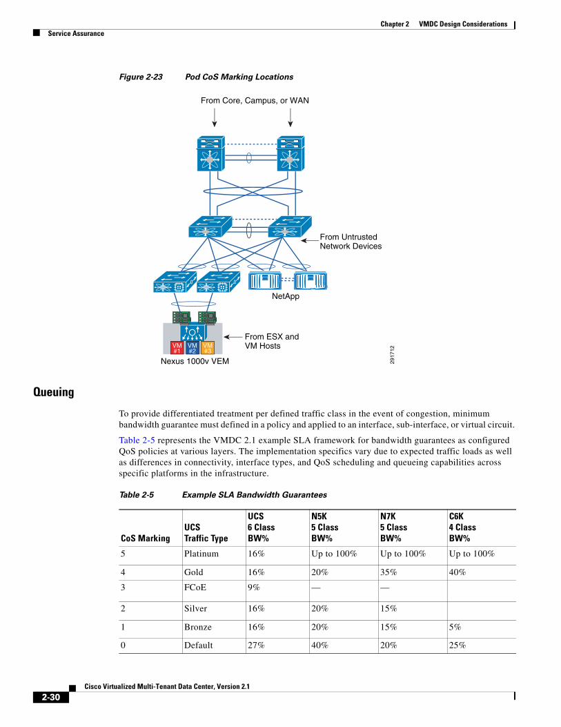
Figure 2-23 Pod CoS Marking Locations
Queuing
To provide differentiated treatment per defined traffic class in the event of congestion, minimum bandwidth guarantee must defined in a policy and applied to an interface, sub-interface, or virtual circuit.
Table 2-5 represents the VMDC 2.1 example SLA framework for bandwidth guarantees as configured QoS policies at various layers. The implementation specifics vary due to expected traffic loads as well as differences in connectivity, interface types, and QoS scheduling and queueing capabilities across specific platforms in the infrastructure.
From ESX andVM Hosts
From UntrustedNetwork Devices
From Core, Campus, or WAN
Nexus 1000v VEM
NetApp
2917
12
VM#1
VM#2
VM#3
Table 2-5 Example SLA Bandwidth Guarantees
CoS MarkingUCSTraffic Type
UCS6 ClassBW%
N5K5 ClassBW%
N7K5 ClassBW%
C6K4 ClassBW%
5 Platinum 16% Up to 100% Up to 100% Up to 100%
4 Gold 16% 20% 35% 40%
3 FCoE 9% — —
2 Silver 16% 20% 15%
1 Bronze 16% 20% 15% 5%
0 Default 27% 40% 20% 25%
2-30Cisco Virtualized Multi-Tenant Data Center, Version 2.1
Chapter 2 VMDC Design ConsiderationsService Assurance
Network AnalysisThe use of network analysis devices is another service readily available in the VMDC 2.1 design. The Cisco Nexus 1000v NAM VSB is integrated with the Nexus 1010 Virtual Services Appliance to provide network and performance visibility into the Nexus 1000V switching deployment. The NAM VSB uses the embedded instrumentation, such as Netflow and Encapsulated Remote SPAN (ERSPAN) on the Nexus 1000V switch as the data source for traffic analysis, application response time, interface statistics, and reporting.
For more information on the Cisco Prime NAM for Nexus 1010 deployment follow the link below:
http://www.cisco.com/en/US/docs/net_mgmt/network_analysis_module_virtual_blade/4.2/install/guide/nexus/nx42_install.html
The following methods of data collection were used in the design:
• NetFlow
• Encapsulated Remote Switched Port Analyzer (ERSPAN)
NetFlow
NetFlow was developed by Cisco to provide better insight into the IP traffic on the network. NetFlow defines flows as records and exports these records to collection devices. NetFlow provides information about the applications in and utilization of the data center network. The NetFlow collector aggregates and assists network administrators and application owners to interpret the performance of the data center environment.
The use of NetFlow is well documented in a traditional network environment, but the Nexus 1000v provides this capability within the virtual network environment. Nexus 1000v supports NetFlow v9 and by default will use the management 0 interface as an export source.
Caution The use of advanced features such as NetFlow will consume additional resources (i.e., memory and CPU, of your ESX host). It is important to understand these resource dynamics before enabling any advanced features.
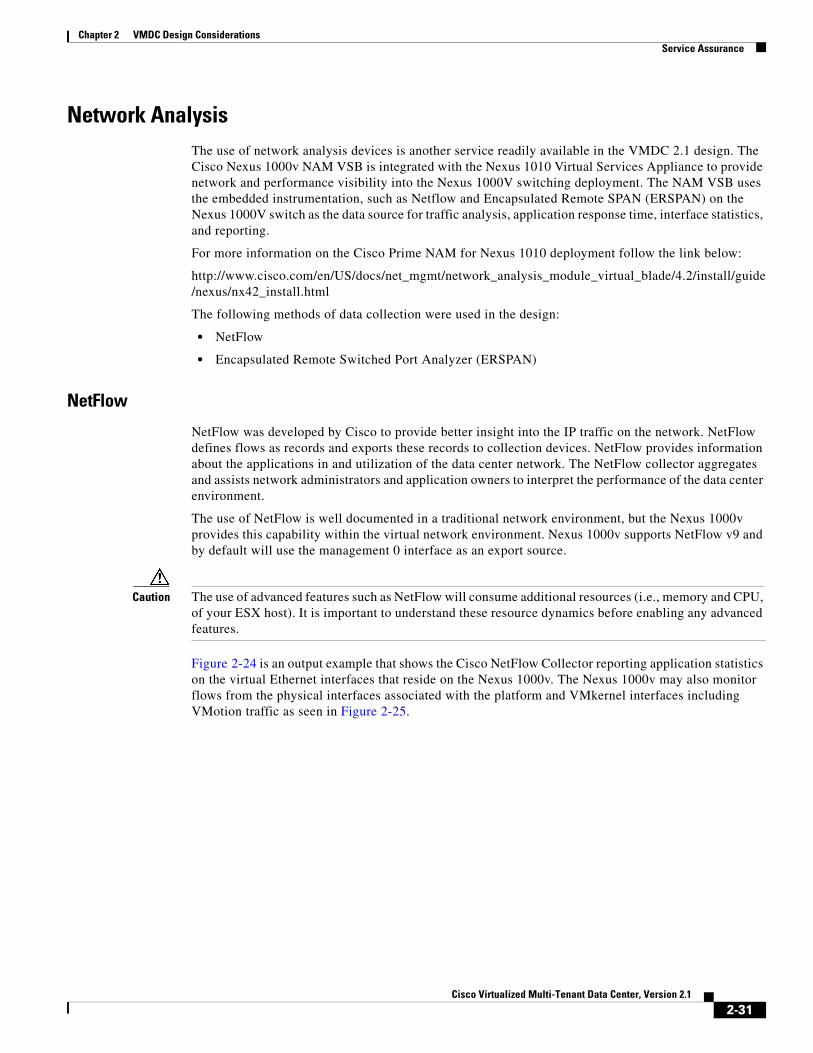
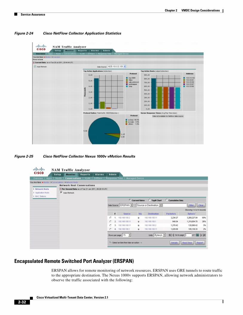
Figure 2-24 is an output example that shows the Cisco NetFlow Collector reporting application statistics on the virtual Ethernet interfaces that reside on the Nexus 1000v. The Nexus 1000v may also monitor flows from the physical interfaces associated with the platform and VMkernel interfaces including VMotion traffic as seen in Figure 2-25.
2-31Cisco Virtualized Multi-Tenant Data Center, Version 2.1
Chapter 2 VMDC Design ConsiderationsService Assurance
Figure 2-24 Cisco NetFlow Collector Application Statistics
Figure 2-25 Cisco NetFlow Collector Nexus 1000v vMotion Results
Encapsulated Remote Switched Port Analyzer (ERSPAN)
ERSPAN allows for remote monitoring of network resources. ERSPAN uses GRE tunnels to route traffic to the appropriate destination. The Nexus 1000v supports ERSPAN, allowing network administrators to observe the traffic associated with the following:
2-32Cisco Virtualized Multi-Tenant Data Center, Version 2.1
Chapter 2 VMDC Design ConsiderationsService Assurance
• The individual vNIC of a virtual machine connected to a VEM
• The physical ports associated with the ESX host
• Any port channels defined on the VEM
This flexibility allows the ERSPAN session to not only monitor data associated with virtual machines, but to monitor all traffic associated with the ESX host including VMkernel, VMotion, and service console data. Converging all of these traffic types onto two or a maximum of four CNAs per-ESX host simplifies not only the physical design of the data center but the configuration of the capture points as well.
In the validation of this solution, the final destination for ERSPAN traffic was the Virtual Network Analysis Module (vNAM) resident in Nexus 1010.
For more information on configuring ERSPAN on the Nexus 1000v follow this link:
http://www.cisco.com/en/US/docs/switches/datacenter/nexus1000/sw/4_0_4_s_v_1_2/system_management/configuration/guide/n1000v_system_9span.html
Caution The use of advanced features such as ERSPAN will consume additional resources (i.e., memory and CPU of the ESX host). It is important to understand these resource dynamics before enabling any advanced features.
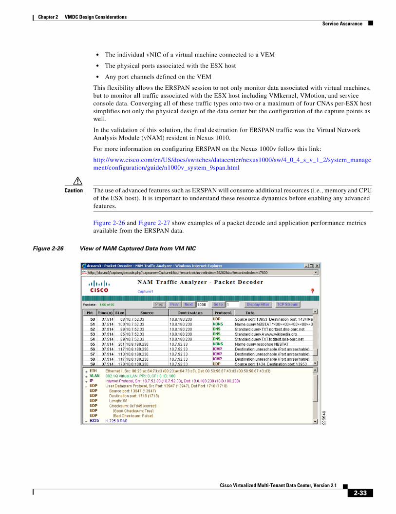
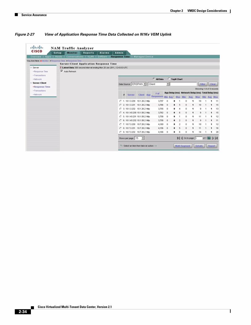
Figure 2-26 and Figure 2-27 show examples of a packet decode and application performance metrics available from the ERSPAN data.
Figure 2-26 View of NAM Captured Data from VM NIC
2-33Cisco Virtualized Multi-Tenant Data Center, Version 2.1
Chapter 2 VMDC Design ConsiderationsService Assurance
Figure 2-27 View of Application Response Time Data Collected on N1Kv VEM Uplink
2-34Cisco Virtualized Multi-Tenant Data Center, Version 2.1