VLT® HVAC Drives Technical Reference Supplement...EN 55011-1B, the output wiring must be shielded,...
20
www.danfossdrives.com 37 million VLT® HVAC Drives Technical Reference Supplement tons of CO 2 are saved every year by the 4 million VLT® Drives installed worldwide from Danfoss
Transcript of VLT® HVAC Drives Technical Reference Supplement...EN 55011-1B, the output wiring must be shielded,...

www.danfossdrives.com
37 million
VLT® HVAC Drives Technical Reference Supplement
tons of CO2 are saved every year by the 4 million VLT® Drives installed worldwide from Danfoss

2
1.00
0.75
0.50
0.25
2000
1000
100
6543
2
60504030
20
101.0 1.2 1.4 1.6 1.8 2.0
0.1 0.2 0.3 0.4 0.5 0.6Frequency
Moto
r vo
ltag
eM
oto
r vo
ltag
e
0.7 0.8 0.9 1.0
χ
[s][s]
175Z
A05
2.11
Motor Thermal ProtectionIntegrated motor thermal protection is provided by the VLT HVAC Drive in two ways. To protect against motor overheating, input from a motor thermistor is accommodated. The drive monitors changing temperature conditions in the motor as speed and load vary to detect overheating conditions. Monitoring ensures detection of failure in the motor’s cooling air supply.
The other method calculates motor temperature using current, frequency and time. In this method, the drive can predict impending motor thermal overload conditions. The drive warns of these conditions and displays the amount of thermal load in percentage until thermal overload would be reached. The prediction accounts for reduction in the speed of the motor’s cooling fan. Even at low speeds, the drive meets I2t Class 20 electronic motor overload standards.
The graph below shows the amount of time that the drive can provide a level of current to the motor at rated motor frequency (1), 20% of rated motor frequency (0.2) and 200% of rated motor frequency (2).
The Danfoss VLT® HVAC Drive is programmed with user specific options ready to go right out of the box. Many of the important cost, energy, and maintenance saving features of the Danfoss HVAC are built-in. Benefits from these advantages begin as soon as the drive is started.
Automatic Energy OptimizationAutomatic Energy Optimization (AEO) is one of the VLT HVAC Drive’s most advanced features. The drive continuously monitors the load on the motor and adjusts the output voltage to maximize motor and drive efficiency. Under light load, the voltage is reduced, as shown in the graph below. The shaded area represents the voltage reduction. Motor current is minimized. The motor benefits from increased efficiency, reduced heating and quieter operation. There is no need to select a V/Hz curve because the drive automatically adjusts motor voltage for optimum energy savings.
Benefits of AEO:• Automatic compensation for oversized motors• Automatic compensation for system load change• Automatic compensation for seasonal changes• Automatic compensation for low motor loading• Reduced energy consumption• Reduced motor heating• Reduced motor noise
1.00
0.75
0.50
0.25
2000
1000
100
6543
2
60504030
20
101.0 1.2 1.4 1.6 1.8 2.0
0.1 0.2 0.3 0.4 0.5 0.6Frequency
Moto
r vo
ltag
eM
oto
r vo
ltag
e
0.7 0.8 0.9 1.0
χ
[s][s]
175Z
A05
2.11
Energy savings with AEO
Automated Operational Features
Current at variation in rated motor frequency

3
Application Class THD (%)
Sensitive Applications 3% Airports Hospitals Telecommunications FacilitiesGeneral Applications 5% Office Buildings SchoolsDedicated Systems 10% Factories
Built-in Harmonic SuppressionLimiting harmonic distortion on the power line was part of the VLT HVAC Drive design criteria. As a result, filter reactors are internal to the drive. Connected between the input rectifier and the DC bus capacitor, these are called DC link reactors (see figure below). Two DC link reactors, one in the positive DC bus and one in the negative DC bus, provide very low power line harmonics. The DC link reactors reduce RMS input current drawn from the building power system by more than 40% compared to drives without inductors.
AC Line ReactorsWhen an adjustable frequency drive has no built-in harmonic filtering, it is often necessary to add external filtering for use in HVAC applications. This is the purpose of AC line reactors. AC line reactors have to be sized approximately 50% larger than similar DC link reactors, and they require a separate enclosure for mounting. Current passing through external reactors causes electrical loss resulting in heat generation. AC line reactors may act as a buffer between the AC power line and the drive, however, the VLT HVAC Drive uses metal oxide varistors (MOVs) and R/C snubber circuitry to protect the drive input from power line noise. A buffer is unnecessary. When harmonic requirements on the power line are very stringent, or if the supply power is soft, AC line reactors are available for VLT HVAC Drive as an option.
Harmonic AnalysisVarious characteristics of a building’s electrical system determine the exact harmonic contribution of the drive to the THD of a facility and its ability to meet IEEE standards. Generalizations about the harmonic contribution of drives on a specific facility is difficult. When requested, Danfoss can provide a computerized analysis of the system harmonics to determine drive effects.
HarmonicsElectrical devices with diode rectifiers, such as fluorescent lights, computers, copiers, fax machines, various laboratory equipment and telecommunications systems, can add harmonic distortion to a building’s power line. Adjustable frequency drives which use a diode bridge input also contribute to the total harmonics of the building.
Most drives do not draw current uniformly from the power line. This non-sinusoidal current has components which are multiples of the fundamental current frequency. These components are referred to as harmonics. It is important to control the total harmonic distortion within a facility. Although the harmonic currents do not directly affect electrical energy consumption, they generate heat in wiring and transformers and can effect other devices on the same power line.
Low Harmonic DistortionVLT HVAC Drives are designed for the HVAC environment, where harmonic distortion is a concern. The level of harmonic distortion acceptable depends upon the type of facility and the amount of interaction between electrical equipment . Total harmonic distortion (THD) is a summation of harmonic distortion for a building expressed in percentage. IEEE 519 is a standard by the Institute of Electrical and Electronic Engineers which rates the THD acceptable in various building categories, as shown in the following table. VLT HVAC Drives can meet the stringent harmonic level of 3% for sensitive applications. Drives designed for industrial use and adapted for HVAC applications are electronically “noisy” and may require add-on hardware to achieve similar levels.
IEEE 519 standards for total harmonic voltage distortion
Automated Operational Features
DC link reactors

4
For drives with a maximum carrier frequency greater than 4.5 kHz, an automatic feature of the VLT HVAC Drive is load dependent carrier frequency control. This feature allows the motor to benefit from as high a carrier frequency as the load permits. The range of carrier frequencies are as follows:
Short Circuit ProtectionThe VLT HVAC Drive provides inherent short circuit protection with a very fast acting fault-trip circuit by sensing current on all three drive output phases. The use of insulated gate bi-polar transistors (IGBT) in the VLT HVAC Drive means very high-speed switching and rugged performance. And, because the VLT HVAC Drive creates a near perfect sinusoidal current, it automatically minimizes motor noise while providing accurate motor control and smooth motor performance.
EMI Filtering and RFI ShieldingElectromagnetic interference (EMI) and radio frequency interferences (RFI) can have effects on a building power supply similar to those of harmonic distortion. EMI is conducted through the AC power line while RFI is transmitted through the air. VLT HVAC Drive 230 V and 460 V series drives are designed to comply with stringent European standards. EN 55011-1B, for highly restrictive residential applications, and the less restricted industrial standard, EN 55011-1A. To comply with EN 55011-1A, the output wiring must be shielded, properly terminated, and not over 500 feet (150 m) long. To comply with EN 55011-1B, the output wiring must be shielded, properly terminated, and not over 155 feet (50 m).
All VLT HVAC Drives 10 HP at 460 volts and through 3 HP at 208 volts have built-in EMI and RFI filtering and comply with both standards without adding options. All other VLT HVAC Drives are available with optional filters to meet these standards. Consult Danfoss with your requirements.
Automatic Switching Frequency ModulationAn adjustable frequency drive sends short electrical pulses to a motor to control the voltage and current provided. The carrier frequency of a drive is the rate of these pulses. A low carrier frequency (slow pulsing rate) causes noise in the motor, making a high carrier frequency preferable. A high carrier frequency, however, generates heat in the drive thereby limiting the amount of current available to the motor. Automatic Switching Frequency Modulation (ASFM) regulates these conditions automatically to provide the highest carrier frequency without overheating the drive. By providing a regulated high carrier frequency, ASFM quiets motor operating noise at slow speeds, when audible noise control is critical, and produces full output power to the motor when the demand requires. Systems without ASFM can do one or the other, but not both. An important benefit is no need to derate output at high load. (See the graph below representing 15-60 HP drives at 460 VAC and 5-30 HP at 208 VAC.) ASFM adjusts the frequency based on motor current demand rather than motor speed to provide the best carrier frequency possible, matching both performance and noise control.
Derating for High Carrier FrequencyAll VLT HVAC Drives are designed for continuous, full load operation at carrier frequencies from 3.0 to 4.5 kHz. Most drives can be set to operate at a higher carrier frequency. Since a higher carrier frequency generates more heat in the drive, the output current rating of the drive must be derated when a carrier frequency greater than 4.5 kHz is used.
Automated Operational Features
Carrier frequency and load with AFSM
Switching frequency [kHz] Min Max Factory Set
To 3 HP, 208 V 3.0 10.0 4.5
5 to 30 HP, 208 V 3.0 14.0 4.5
40 to 60 HP, 208 V 3.0 4.5 4.5
To 10 HP, 460 V 3.0 10.0 4.5
To 10 HP, 600 V 4.5 7.0 4.5
15 to 60 HP, 460 and 600 V 3.0 14.0 4.5
75 to 300 HP, 460 and 600 V 3.0 4.5 4.5
350 to 600 HP, 460 V 3.0 4.5 4.5
20
ASFM
Carr
ier F
requ
ency
(kH
z)
Load (%)
1816141210
86420
0 10 20 30 40 50 60 70 80 90 100 110

5
the drive’s current capability under normal operation (from an undersized drive and motor), current limit reduces the drive output frequency to slow the motor and reduce the load. An adjustable timer is available to limit operation in this condition for 60 seconds or less. The factory default limit is 110% of the rated motor current to minimize overcurrent stress. Drives intended for heavy industrial applications may have an unnecessarily high limit for HVAC applications.
Galvanic Isolation of Control TerminalsAll control terminals and output relay terminals are galvanically isolated from the power line. This means the drive controller is completely protected from the input current. The output relay terminals require their own grounding. This isolation meets the stringent protective extra-low voltage (PELV) requirements for isolation and ensures safe connection to building management systems.
The components that make up the galvanic isolation are shown in the diagram below:1. Power supply, including signal isolation.2. Gate drive for the IGBTs, the trigger transformers and opto-couplers.3. The output current Hall effect transducers.
Motor Soft StartThe drive supplies the right amount of current to the motor to overcome load inertia and then brings the motor up to speed. This avoids full line voltage being applied to a stationary or slow turning motor which generates high current and heat. Benefits from this inherent soft start drive feature are reduced thermal load and extended motor life, reduced mechanical stress on the system, and quieter system operation.
Resonance DampingHigh frequency motor resonance noise can be eliminated through the use of resonance damping. The VLT HVAC Drive automatically adjusts the amount of damping required. Manual adjustment is also possible.
Power Fluctuation PerformanceThe drive withstands powerline fluctuations such as transients, momentary dropouts, short voltage drops and surges. The drive automatically compensates for input voltages ±10% from the nominal to provide full rated motor voltage and torque. With auto restart selected, the drive will automatically power-up after a voltage trip. And with flying start, the drive synchronizes to motor rotation on an already spinning motor.
Overtemperature Protection with Automatic DerateAutomatic derate prevents tripping at high temperature. Temperature sensors inside the drive protect its power components from overheating. Unlike competitor’s drives, the VLT HVAC Drive can be set to automatically reduce its carrier frequency to help maintain temperature within safe limits. After reducing the carrier frequency, the drive will then reduce the output frequency and current to avoid an overtemperature trip. The drive reduces speed as much as 30% before it shuts down.
Current Measurement on All Three Motor PhasesOutput current to the motor is continuously measured on all three phases. This protects both the drive and motor against short circuits, ground faults, and lost phases. Output ground faults are instantly detected. Output contactors may be repeatedly used with no damage to the drive. Current is evenly spread across the three wires. If a motor phase is lost, the drive stops immediately and reports which phase is missing.
Auto Ramping A motor trying to accelerate a load too quickly for the current available can cause a drive to trip. The same is true for too quick of a deceleration. The VLT HVAC Drive protects against this by extend-ing the motor ramping (acceleration or decelera-tion rate) to match the available current. This automatic feature ensures no-trip operation and smooth motor starts.
Temperature Controlled Drive FansThe internal drive cooling fan is temperature controlled by sensors within the drive. This means that the cooling fan often is not running during low load operation, in sleep mode or standby. This reduces drive noise, increases total drive efficiency and extends the operating life of the fan.
Current Limit CircuitDuring acceleration, the current required to accelerate a load can exceed the motor current limit, damaging the motor. To prevent damage under this condition, the drive discontinues accelerating the motor until the current demand is reduced to normal levels. Acceleration then automatically continues. Should a load exceed
Automated Operational Features
Galvanic isolation

6
Flying StartFlying start allows a drive to synchronize with a motor rotating at any speed, up to full speed, in either direction. After synchronizing with the motor, the control smoothly brings the drive to the desired speed and in the desired direction. This prevents trips and minimizes mechanical stress to the system, since the motor receives no abrupt change in speed.
Sleep ModeSleep mode automatically stops the motor when demand is at a low level for a period of time. When the system demand increases, the drive restarts the motor to reach the required output. Sleep mode has great energy savings capability and reduces wear on driven equipment. Unlike a time clock setback, the drive is always available to run when the preset “wakeup” demand is reached.
Run PermissiveThe drive has the capability to accept a remote “system ready” signal prior to operation. This feature is useful for a wide range of applications. When selected, the drive will remain stopped until receiving permission to start. Run permissive ensures that dampers, exhaust fans, or other auxiliary equipment are in the proper state before the drive is allowed to start the motor.
Full Torque at Reduced SpeedUnlike variable torque drives, which provide reduced motor torque at reduced output frequency, or constant torque drives, which provide excess voltage, heat and motor noise at less than full speed, the VLT HVAC Drive follows a variable V/Hz curve to provide full motor torque even at reduced speeds. In direct drive fan systems, full torque is available for all range of operation. Full output torque can coincide with the max i mum designed operating speed of drive controlled equipment, up to 60 Hz.
Frequency BypassIn some applications, the system may have operational speeds that create a mechanical resonance. This can generate excessive noise and possibly damage mechanical components in the system. The drive has four programmable bypass frequency bandwidths. These allow the motor to stepover speeds which induce system resonance.
Motor PreheatWhen a motor must start in a cold or damp environment, such as in a cooling tower, a small amount of DC current can be trickled continuously into the motor to protect it from condensation and the effects of a cold start. This can extend the operational life of the motor and eliminate the need for a space heater.
The VLT HVAC Drive capabilities go far beyond its many automated features. The VLT HVAC Drive has incredible flexibility and built-in advanced technology. Each system can be customized for peak performance by choosing from options at your fingertips. The VLT HVAC Drive can expand the capability of a system while simplifying its operation, eliminating peripheral equipment and reducing cost.
Automatic Motor AdaptationAutomatic Motor Adaptation (AMA) is an advanced, automated test procedure that measures the electrical characteristics of the motor. AMA provides the drive with an accurate model of the motor to optimize performance and efficiency. Running the AMA procedure also maximizes the Automatic Energy Optimization feature of the drive. AMA is performed without the motor rotating and without uncoupling the load from the motor. This greatly simplifies the procedure.
Built-in PID ControllerThe Proportional, Integral, Derivative (PID) controller is built into VLT HVAC Drives, eliminating the need for auxiliary control devices. The PID controller maintains constant control of closed loop systems where regulated pressure, flow, temperature, or other system requirements must be regulated. The drive operates the motor speed in response to feedback signals from remote sensors measuring the system status.
Two Feedback SignalsVLT HVAC Drives accommodate two feedback signals from two different devices. This unique feature allows regulating a system with different setpoint zones. The drive makes control decisions by comparing the two signals to optimize system performance. In open loop systems, the reference signals do not effect operation of the drive but can be displayed for system status, as warnings, or as input data for a serial network.
Self-relianceBecause the VLT HVAC Drive is designed specifically for HVAC applications, the drive can operate without dependence on a building automation system. This can eliminate the need for an additional PID controller and I/O modules.
Automatic RestartThe drive can be programmed to automatically restart motors after a trip. This feature eliminates the need for manual reset of the drive and enhances automated operation for remotely controlled systems where having someone restart the drive is inconvenient or impossible.
Custom Application Features

7
Motor NoiseHigh frequency pulsing of the drive output section can cause noise in the motor. The design of the motor determines the amount of noise. Changing the carrier frequency of the drive may quiet a noisy motor. If this is not adequate, an LC filter may be connected. Although the noise at the motor will be reduced, there is some noise from the LC filter. Be sure that the filter is located so that its sound is not objectionable.
Motor StressThe output of any adjustable frequency drive creates stress on the motor. The VLT HVAC Drive controls this stress through “soft switching” IGBTs on the smaller drives and output reactors on the largest drives. However, it is still desirable to use motors designed for use with an adjustable frequency drive. Some motors, especially smaller ones, may lack phase insulation paper and other important features. Ideally, a motor should meet the specifications of NEMA MG-1, part 31.
It may be desirable to specify an LC filter for use in conjunction with motors unable to meet these standards, long motor leads, or multiple motors.
Motor Lead LengthLong motor leads can produce high peak voltages at the motor, contributing to motor stress. This should be avoided. If it is not possible to avoid long motor leads, a motor which meets NEMA MG-1, part 31, and an LC filter should be used.
In addition, if the motor lead length is longer than 500 feet (150 m), an LC filter should always be used. For multiple motor installations, the length of all the motor leads must be added. The LC filter is necessary to reduce the capacitive earth leakage currents as well as the peak voltage at the motor. If the LC filter is not used, the drive may overcurrent or ground fault trip.
CE LabelIn addition to being UL and C-UL labeled, all VLT HVAC Drive are CE labeled. The CE label was introduced to show that a product complies to relevant European Economic Union directives. For AC drives, there are three directives: Machine Directive (89/392/EEC), Low Voltage Directive (73/23/EEC), and the EMC Directive (89/336/EEC). The EMC directive covers electromagnetic compatibility. The directive states that, when properly installed, the product will not interfere with other devices as defined in the directive. All VLT HVAC Drive 208 V and 460 V drives comply with all three directives. A declaration of conformity can be issued, if requested.
Four Programmable SetupsThe drive has four independent setups that can be programmed. Independent setups are used, for example, to change speed references, or control multiple motors, or for day/night or summer/winter operation. The active setup is displayed on the LCP. Using multi-setup, it is possible to switch between setups through digital inputs or a serial interface. Setup data can be copied from drive to drive by downloading the information from the removable LCP.
DC Braking Some HVAC applications may require braking a motor to slow or stop it. Applying DC current to the motor will brake the motor and eliminate the need for a separate motor brake. DC braking can be set to activate at a predetermined frequency or upon receiving a signal. The rate of braking can also be programmed.
Input or Output Switch ing ProtectionThe input or output of the drive may be dis con nect ed while the drive is running without the need for interlocks to protect the drive.
Plenum MountingVLT HVAC Drives can be plenum mounted. The drives meet the UL requirements for installation in air handling compartments. When mounting the drive in the plenum, all requirements for clearance, temperature and humidity apply.
High Breakaway TorqueFor high inertia or high friction loads, high torque is available for easy starting to reach the set point operating speed. The breakaway current can be set for up to 160% and 0.5 seconds. Current limit protection reduces stress on all portions of the system.
BypassAn automatic or manual bypass is an available option. The bypass allows the motor to operate at full speed when the drive is not operating and allows the drive to be taken off-line for routine maintenance.
LC FiltersLC filters may be specified as an option with any VLT HVAC Drive through 300 HP.
The LC filter lengthens the voltage rise time to the motor, and reduces the peak voltage and ripple current at the motor. Depending upon the application, motor, and the length of motor leads, an LC filter may be desirable.
Custom Application Features

8
High Frequency WarningUseful in staging on additional equipment such as pumps or cooling fans, the drive can warn when the motor speed is high. A specific high frequency setting can be entered into the drive. If the drive’s output exceeds the set warning frequency, the drive displays a high frequency warning. A digital output from the drive can be made to signal external devices to stage on.
Low Frequency WarningUseful in staging off equipment, the drive can warn when the motor speed is low. A specific low frequency setting can be selected for warning and to stage off external devices. The drive will not issue a low frequency warning when it is stopped nor upon start-up until after the set frequency has been reached.
High Current Warning This function is similar to high frequency warning (see above), except a high current setting is used to issue a warning and stage on additional equip-ment. The drive will not issue a false warning dur-ing start-up due to a high starting current, since the function is not active until the set current has been reached.
Low Current WarningThis function is similar to low frequency warning (see above), except a low current setting is used to issue a warning and stage off equipment. The drive will not issue a low current warning when stopped nor upon start-up until after the set current has been reached.
Lost Serial Interface The drive can detect loss of serial communication when under control of a serial bus. A time delay of up to 99 seconds is selectable to avoid a drive response due to interruptions on the serial com-munications bus. When the delay is exceeded, options available in response to lost serial communication are for the drive to maintain its last speed, go to maximum speed, go to a preset speed, stop, or stop and issue a warning.
The Danfoss VLT HVAC Drive arrives pre-programmed with various fault, warning and alarm responses. Additional alarm and warning features can be easily selected.
No Load/Broken Belt Warning This feature can be used for monitoring the V-belt of a fan. After a low current limit has been stored in the drive, the drive can be programmed to trip and issue an alarm or to continue operation and issue a warning if loss of the load is detected.
Operation at OvertemperatureBy default, the drive will issue an alarm and trip at overtemperature. If Autoderate and Warning is selected, the drive will warn of the condition but continue to run and attempt to cool itself by first reducing its carrier frequency. Then, if necessary, it will reduce its output frequency.
High and Low Reference WarningIn open loop operation, the reference signal directly determines the speed of the drive. The display shows a flashing reference high or low warning when the programmed maximum or minimum is reached.
High and Low Feedback WarningIn closed loop operation, the selected high and low feedback values are monitored by the drive. The display shows a flashing high or flashing low warning when appropriate. The drive can also monitor feedback signals in open loop operation. While the signals will not affect the operation of the drive in open loop, they can be useful for system status indication or as data supplied to a serial network. The drive handles 39 different units of measure for system flexibility.
Phase Imbalance or Phase Loss Excessive ripple current in the DC bus indicates either an input power phase imbalance or phase loss. When an incoming power phase to the drive is lost, the default is to issue an alarm and trip the drive to protect the DC bus capacitors. Other options are to warn and reduce output current to 30% of full current or to continue normal operation and issue a warning of lost input phase. While operating a drive connected to a severely imbalanced line may be desirable until the imbalance is corrected, depending upon which input phase is low or missing, the cooling fans on NEMA 12 drives may not oper-ate. An external power supply for the fans can be provided.
Fault, Warning and Alarm Responses:Additional Selectable Options

9
Preset Speeds Flexible operation programming with 16 preset speeds. The drive has four preset jog frequencies, one in each setup, to start the drive, in hand or auto mode, and run it at the preset jog frequency.
Setpoints and Feedback SignalsThe built-in PID controller in the drive maintains the desired system condition (pressure, temperature, flow, etc.) in closed loop operation by adjusting motor speed based upon a setpoint and feedback signal.
A sensor supplies the PID controller with a feedback signal from the system to indicate its current state. The VLT HVAC Drive offers 39 units of measure for the feedback signal for unequalled HVAC system flexibility. Feedback and setpoint values are programmed and displayed using the selected unit.
The difference between the setpoint and the feedback from the system is calculated. The PID controller then adjusts the motor’s speed to satisfy the system requirements. The PID controller’s setpoint can be programmed into the drive, provided by an external signal, or can be the sum of both. (See the figure below.) Only the VLT HVAC Drive accepts two feedback signals and two setpoints, making two-zone regulation possible. In addition, voltage drop in long control cables can be compensated for by using scaling parameters for the analog inputs.
Other programmable drive features include inverse regulation (which means motor speed will decrease when a feedback signal is high), a pre-selected start-up frequency which lets the system quickly reach an operating status before the PID controller takes over, and a built-in lowpass filter to reduce feedback signal noise.
The VLT HVAC Drive allows for additional customization of the internal drive control values for precise command of the drive setpoints, feedback and references. Settings can be modified for exact performance using simple data entry procedures. A reset command reestablishes factory default settings in an instant for reliable drive operation.
Inputs• 4 programmable digital inputs• 2 programmable analog inputs (voltage or current)
Digital input terminals offer 44 separate programmable on/off functions such as start, safety interlock, preset references, setup selections, reset, reverse, run permissive, hand or auto start and more. Analog inputs allow drive control through feedback or reference signals. Analog inputs are in voltages from 0 to 10 VDC and current from 0 to 20 mA with minimum and maximum signal levels programmable.
Outputs• 2 programmable analog/digital outputs (4-20 mA and 0-20 mA)• 2 programmable relay outputs (1 Form C, 240 VAC, 2 A and 1 Form A, 30 VAC, 1 A) - with four additional relays optional
Digital relay outputs can reflect drive status and warnings. Some 74 functions can be programmed including warning for out of current or frequency range, input phase imbalance, and thermal warning, or operational status such as ready, waiting for start, start, running and many others. The analog/digital outputs can be programmed for any of the relay options and, in addition, output frequency, current or power, and external reference and feedback values. All inputs and outputs are available on the serial network communications.
Adjustable Speed RangeFrom 0 Hz setting to 1,000 Hz for motor speed adjustment.
Adjustable Acceleration and Deceleration TimeSelect from 1 to 3,600 seconds to accurately regulate motor acceleration and deceleration times. The drive can respond quickly for fast acting systems, such as with pumps, or over an extended time period to minimize mechanical stress, as in cooling towers applications. Auto ramping, described earlier, is another option based upon motor current demand.
Additional Drive Features
ReferencePresetref.
Externalref.
Setpoint 1
Setpoint 2
Feedback 1
Resultingfeedback
Feedback
Feedbackfunctionpar. 417
Setpoint
Feedback 2Analog FBTerminal 60Pulse FBTerminal 33
Remotereference
Resultingreference
Outputfrequency
PID+ ++
+–+

10
5. DC Capacitor Bank Smooths the DC bus voltage and provides stored energy which can be used to “ride through” short power losses.
6. Inverter Converts DC voltage into controlled AC voltage with a variable frequency.
7. Output Current Sensors Continuously monitors motor current in all three phases to ensure reliable and efficient motor operation under all conditions.
8. Output to the Motor Variable voltage and frequency AC output. Frequency range: to 60 Hz or beyond Voltage range: to 100% of supply voltage By controlling voltage and frequency together, the connected motor can operate the centrifugal fan or pump over a controlled speed range at the highest possible efficiency.
An adjustable frequency drive rectifies AC voltage from the AC line into DC and then inverts this into an AC voltage with controlled voltage and frequency.
The standard, three-phase, asynchronous induction motor is then supplied with variable voltage and frequency power, allowing continuously variable motor speed. The main components of the VLT HVAC Adjustable Frequency Drive are shown to the right and described below.
1. AC Line Supply Three series of drives allow operation at all commercial three-phase voltages from 200 to 600 volts AC. 200 to 240 VAC, 50 / 60 Hz 380 to 460 VAC, 50 / 60 Hz 550 to 600 VAC, 50 / 60 Hz
2. Rectifier A three-phase rectifier bridge that rectifies AC into DC current.
3. Intermediate DC Circuit DC voltage ≅ 1.35 x AC RMS voltage.
4. DC Link Reactors • Filter the intermediate DC circuit voltage. • Provide protection against line transients. • Reduce input RMS current. • Raise power factor reflected back to the line. • Reduce harmonics on the AC input.
VLT HVAC Drive Control Principle
1 2 34
5
67, 8

11
From tables in Specification section, heat loss of drives is 295 and 1430 watts for a total of 1725 watts. Multiplying by 3.3 gives 5693.
Subtracting 100°F from 113°F gives 13.
Dividing 5693 by 13 gives 438 CFM.
Harsh EnvironmentsThe mechanical and electrical components of the VLT HVAC Drive Series drives can be adversely affected by the environment. Contaminants in the air, either solid or liquid, are difficult to quantify and control.
Note: high temperatures, high elevation and harsh environments may increase number of drive faults and may reduce life of drive if proper precautions are not taken.
Airborne LiquidsLiquids in the air can condense in the drive. Water carried in the air is easily measured as relative humidity, but other vapors are often more difficult to measure or control. Steam, oil and salt water vapor may cause corrosion of components. In such environments, use NEMA 12 enclosures rather than NEMA 1. NEMA 12 enclosures limit the exchange of outside air into the drive enclosure. Extremely harsh environments may require a higher level of protection than NEMA 12. Consult Danfoss for complete information.
Airborne SolidsParticles in the air may cause mechanical, electrical or thermal failure in the drive. A NEMA 1 enclosure provides a reasonable degree of protection against falling particles, but it will not prevent the drive fan from pulling dirty air into the drive. A typical indicator of excessive levels of airborne particles is dust around the fan. In dusty environments, use NEMA 12 enclosures.
Use with Isolated Input SourceMost utility power in the United States is referenced to earth ground. Although not in common use in the United States, the input power may be an isolated source. All VLT HVAC Drives, except the VLT6011 (10 HP), may be used with an isolated input source as well as with ground reference power lines.
Ground Leakage CurrentIt is normal for there to be some leakage current from the drive to earth ground. Paths of current leakage are shown on the drawing below. The leakage current will exceed 3.5 mA.
Calculation of Air Flow Required for Cooling the DriveThe air flow required to cool a drive, or multiple drives in one enclosure, can be calculated.1. Determine power loss at maximum output for all drives from data tables in Specifications section.2. Add power loss values of all drives that can operate at same time. Multiple total by 3.3.3. Determine highest temperature of air that will enter enclosure. Subtract this temperature from 113°F.
Note: maximum air temperature to enter enclosure must never exceed 104°F. day/night average temperature must not exceed 95°F.
4. Divide answer from step 2 by answer from step 3.5. When sizing components to provide calculated air flow, be sure to allow for pressure losses as air filters become filled with dirt.6. Outlet for ventilation must be placed higher than top of highest drive in enclosure.
Example:What is the airflow in CFM required to cool 10 hp VLT HVAC drive and 75 hp VLT HAVAC drive, both running at the same time, mounted in an enclosure with an ambient temperature peak of 100°F.
L1
Rectifier
AC LeakageDC Leakage AC + DC Leakage
Earth Plane
IGBTU
V
W
DC link
PE
PE CS
CS
CS CS
CS
L3
L2
Paths of normal current leakage to ground
VLT HVAC Drive Operational Principle

12
Power Loss Ride-throughDuring a power loss, the drive continues to drive the motor until the intermediate circuit (DC bus) voltage drops below the minimum operating level, which corresponds to 15% below the lowest rated drive voltage. There are three series of VLT HVAC Drives. One drive is rated for operation on 200 to 240 volts, another is rated for 380 to 460 volts, and a third for 550 to 600 volts. The power loss ride-through time depends upon the load on the drive and the line voltage at the time of the power loss.
OverloadWhen the torque required to maintain the set frequency, or to accelerate to the set frequency, exceeds the set current limit, the drive will attempt to continue to operate. It automatically reduces the rate of acceleration, or if running at set frequency, reduces the output frequency. If the overcurrent demand cannot be reduced in this manner, the drive shuts down and displays a fault within 1.5 seconds. The current limit level is programmable. Also,the amount of time that the drive will operate in current limit before shutting down can be set by the overcurrent trip delay. This can be set from 0 to 60 seconds, or for infinite operation which is subject to the drive and motor thermal protection.
Output ContactorAlthough not generally a recommended practice, operating an output contactor between the motor and the drive will not cause damage to the drive. Closing a previously opened output contactor may connect a running drive to a stopped motor. This may cause the drive to trip and display a fault.
Input Power DelayTo ensure that the input surge suppression circuitry performs correctly, a time delay between successive applications of input power must be observed. The table below shows the minimum time that must be allowed between applications of input power.
Corrosive ChemicalsIn environments with high temperatures and humidity, corrosive gases such as sulphur, nitrogen and chlorine compounds cause corrosion to occur in the drive. Such chemical reactions rapidly affect and damage electronic components. An indication of corrosion is blackened copper or oxygenation of steel or aluminum. In such environments, it is recommended that the equipment be mounted in a cabinet with fresh air ventilation and that corrosive compounds be kept away from the drive. A non-ventilated cabinet fitted with an air conditioner as a heat exchanger may be used. Conformal coated circuit boards may be specified to reduce the corrosive effects of a harsh environment. Consult Danfoss with complete information on the environment for selection of the proper enclosure or cabinet.
Extreme Operating ConditionsShort Circuit ProtectionCurrent is measured in each of the three output phases. After 5 to 10 ms, if the current exceeds the permitted value, all transistors in the inverter turn off. This provides the most rapid current sensing and the greatest protection against nuisance trips. A short circuit between two output phases will cause an overcurrent trip.
Ground Fault ProtectionThe drive can sense a ground fault on any of the output phases and will shut down and display a fault within 100 ms.
Motor-generated OvervoltageThe DC voltage in the intermediate circuit (DC bus) increases when the motor acts as a generator. This can occur in two ways:
1. The load drives the motor when the drive is operated at a constant output frequency. This is generally referred to as an overhauling load.2. During deceleration, if the inertia of the load is high, the load is light, and the deceleration time of the drive is set to a short value.
The VLT HVAC Drive cannot regenerate energy back to the input. Therefore, it limits the energy accepted from the motor when set to enable autoramping. The drive attempts to do this by automatically lengthening the decel time, if the overvoltage occurs during deceleration. If this is unsuccessful, or if the load drives the motor when operating at a constant frequency, the drive will shut down and display a fault when a critical DC bus voltage level is reached.
Operational Principle
Input voltage 380 V 415 V 460 V 600 VWaiting time 48 sec 65 sec 83 sec 133 sec

13
Voltage Rise Time and Peak Voltage on the MotorVoltage rise time is the amount of time for a voltage pulse at the motor to go from 10% to 90% of the DC bus voltage. The rise time is determined by:1. Switching speed of the inverter power components.2. Motor leads (type, size, length, and shielding).3. Inductors or filters wired between the drive and the motor.
Peak voltage is the maximum voltage that will be applied to the motor windings. Self-inductance of the motor’s stator windings causes an instantaneous voltage overshoot when an electrical pulse is applied to the motor. The voltage level at this instantaneous overshoot is the peak voltage. The peak voltage is determined by:1. Rise time of the pulse.2. DC bus voltage.
Motor insulation is stressed by both excessively short rise time and high peak voltages. Motors without phase coil insulation are especially susceptible to damage.
Short motor leads help keep the peak voltage levels down.
If motors without phase coil insulation must be used, or if lead lengths are long, an output inductor or LC filter should be added to the drive.
Due to all the variables involved that determine voltage rise time and peak voltage, it is difficult to quantify the values applied to the motor. Every installation will be different.
Typical values are given here. Peak voltage is measured at the motor terminals between two phases.
To 10 HP Motor lead Input Rise Peaklength voltage time voltage160 feet 460 V 0.4 µsec. 950 V500 feet 460 V 1.3 µsec. 1300 V 100 feet 600 V 0.36 µsec. 1360 V
15 through 60 HPMotor lead Input Rise Peaklength voltage time voltage160 feet 380 V 0.1 µsec. 900 V500 feet 380 V 0.2 µsec. 1000 V100 feet 600 V 0.38 µsec. 1430 V
75 through 300 HP Motor lead Input Rise Peaklength voltage time voltage45 feet 460 V 0.78 µs 815 V65 feet 460 V 0.84 µs 915 V35 feet 600 V 0.80 µs 1122 V
350 through 600 HPMotor lead Input Rise Peaklength voltage time voltage65 feet 460 V 1.2 µs 760 V
Acoustic Noise from the DriveThe acoustic noise from the drive comes from two sources:1. DC bus coils2. Integral fan
Below are the typical dB values measured at a distance of 1 meter (39 inches) from the unit at full load:
To 5 HP 208 V; to 10 HP 460 VNEMA 1 50 dBNEMA 12 62 dB
7.5 to 25 HP 208 V; 15 to 60 HP 460 VNEMA 1 61 dBNEMA 12 66 dB
VLT 6072, 6102, 6122 460 VNEMA 1 67 dBNEMA 12 66 dB
30 to 60 HP 208 V; 75 to 300 460 VNEMA 1 70 dBNEMA 12 75 dB
350 to 600 HP 460 VNEMA 1 and NEMA 12 82 dB
To 10 HP 600 V
NEMA 1 62 dB
15 to 75 HP 600 VNEMA 1 66 dB
100 to 300 HP 600 VNEMA 1 75 dB

14
If a drive is operated at temperatures above the rated temperature, derating the continuous output current is necessary. The following graphs show the required derating.
Maximum Ambient Temperatures and DeratesFigures A and B show the percent of full output current that can be obtained continuously at various ambient temperatures. The temperatures given are the maximum ambient temperatures for the drives. The average ambient temperature over a 24 hour period must be at least 9°F below the maximum value. This is to ensure no degradation in the life expectancy of drive components.
Maximum Ambient Temperature oF
oMaximum Ambient Temperature oF
Figure A
Figure BFigure B
Drive Current Power
NEMA 1 208 & 230 VAC 5 - 60 hp
NEMA 1 460 VAC 15 - 600 hp
NEMA 1 600 VAC 15 - 300 hp
NEMA 12 ALL ALL
Figure A
Drive Current Power
NEMA 1 208 & 240 VAC 1 - 3 hp
NEMA 1 460 VAC 1 - 10 hp
NEMA 1 600 VAC 1 - 10 hp
100%
90%
80%
70%
60%
50%
40%
30%
20%
10%
0%70° 80° 90° 100° 110° 120° 130° 140°
70° 80° 90° 100° 110° 120° 130° 140°
Out
put V
olta
ge
100%
90%
80%
70%
60%
50%
40%
30%
20%
10%
0%
Out
put V
olta
ge
15
Derate at High AltitudeThe VLT HVAC Drive is designed to provide full rated output current at full rated ambient temperature for altitudes up to 3,300 feet (1000 meters). Below 3,300 feet altitude, no derating for altitude is necessary. Above 3,300 feet, the ambient temperature, or the maximum continuous output current must be derated.
The most common solution is to reduce the output current from the drive when it is used at high altitudes. The graph below shows that the output current from the drive must be reduced by about 1.8% for every 1000 feet above 3,300 feet.
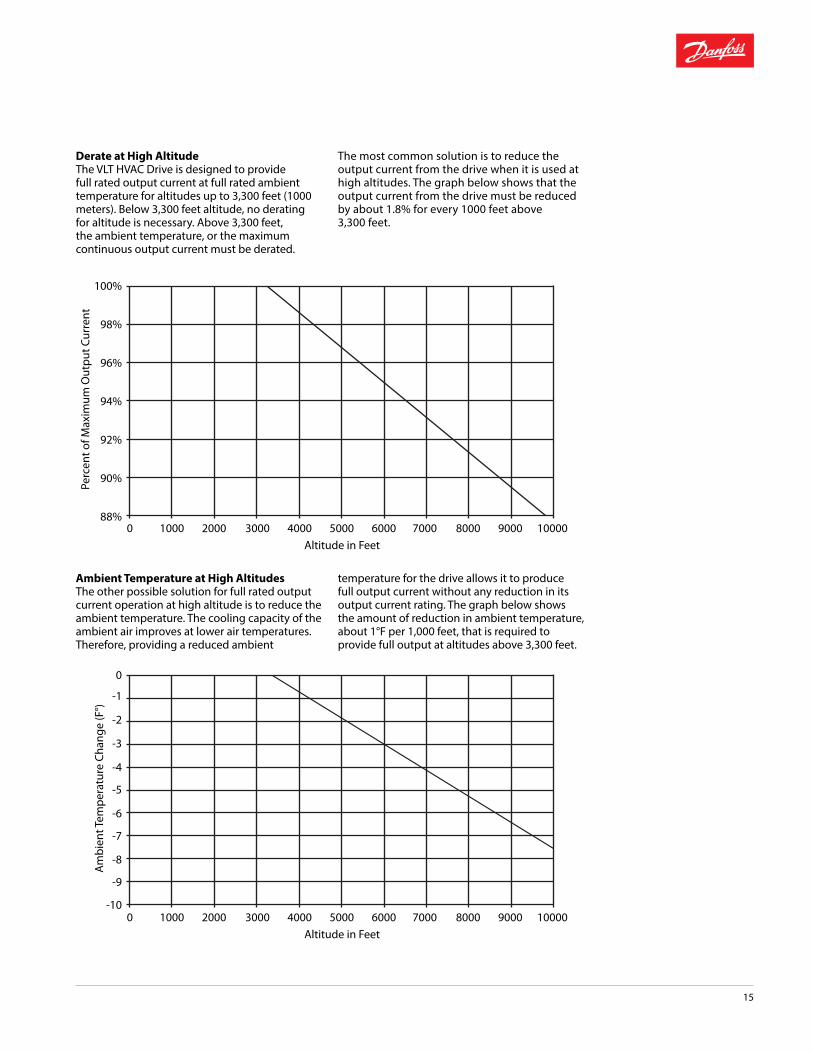
Ambient Temperature at High AltitudesThe other possible solution for full rated output current operation at high altitude is to reduce the ambient temperature. The cooling capacity of the ambient air improves at lower air temperatures. Therefore, providing a reduced ambient
temperature for the drive allows it to produce full output current without any reduction in its output current rating. The graph below shows the amount of reduction in ambient temperature, about 1°F per 1,000 feet, that is required to provide full output at altitudes above 3,300 feet.
100%
98%
96%
94%
92%
90%
88%0 1000 2000 3000 4000 5000
Altitude in Feet
Perc
ent o
f Max
imum
Out
put C
urre
nt
6000 7000 8000 9000 10000
0
-1
-2
-3
-4
-5
-6
-7
-8
-9
-100 1000 2000 3000 4000 5000
Altitude in Feet
Am
bien
t Tem
pera
ture
Cha
nge
(F°)
6000 7000 8000 9000 10000

16
EfficiencyThe efficiency percentage of the VLT HVAC Drive shown in the following graph is based upon a carrier frequency of 4.5 Hz. The efficiency is relatively constant over the normal operating range of the drive. The efficiency of the drive decreases slightly as the carrier frequency is increased. It also decreases slightly as motor leads are lengthened. Although a higher carrier frequency will decrease the VLT HVAC Drive efficiency slightly, it actually improves the efficiency of larger motors. This is because, at higher carrier frequencies, the output wave form more closely approximates a pure sine wave. System efficiency for both drive and motor can be determined by multiplying the drive efficiency (from the graph below) times the motor efficiency.
The efficiency of the motor connected to the drive depends on how closely the output from the drive resembles a sine wave. The sine wave output generated by the VVC+ of the VLT HVAC Drive very closely approximates a pure sine wave. The efficiency generally is just as high as when operated from the power line.
Because of the drive’s Automatic Energy Optimization feature, the efficiency and power factor of the motor at light load will likely be better when run from the drive than if the motor were operated directly from the AC power line. Being able to reduce the V/Hz ratio of a lightly loaded motor improves the efficiency of the motor. The Automatic Energy Optimization feature of the VLT HVAC Drive takes full advantage of this system efficiency increase. The advantage is even more significant in larger motors than in small.
Derating for Running at Low SpeedWhen a centrifugal pump or fan is driven by a VLT HVAC Drive, it is generally not necessary to protect the motor from overheating at low speed, as is often the case with constant torque loads. The reduced power requirement of the load at low speed automatically provides the load reduction that the motor requires.
This assumes that the maximum output frequency of the drive closely corresponds with the maximum normal line frequency of the motor. If the system is designed for full torque at a reduced motor frequency, provision for adequate motor cooling may have to be made. Consult Danfoss with application details.
Derating for Long Motor Leads or Leads of Excessive GageAll VLT HVAC Drives may use unshielded leads up to 1000 feet long, and shielded leads up to 500 feet long without derate. Metallic conduit should be considered shielded for this purpose.
The VLT HVAC Drive has been designed to be operated with motor leads of a range of gauges. Using leads of a smaller gauge may overheat the conductors and be in violation of electrical codes. Using leads of a larger gauge may not properly fit the terminal blocks. They may also cause excessive ground current leakage, which may require derating the drive’s output current. The derate is 5% per gauge size larger than the maximum shown in the Specifications section of the Installation Manual or Design Guide.
Vibration and ShockThe VLT HVAC Drive has been tested according to a procedure based on the IEC 68-2-6/34/35 and 36. These tests subject the drive to 0.7 g forces, over the range of 18 to 1,000 Hz random, in three directions for two hours. All VLT HVAC Drives comply with requirements that correspond to these conditions when the unit is wall or floor mounted, as well as mounted within panels bolted to walls or floors.
Displacement Power Factor 0.98 or greater at all speeds and loads.
Seismic Conformity

17
Main Fusing/Drive FusingDanfoss can supply fuses in conjunction with other options.
Drive FusesDrive fuses are located ahead of the drive and are UL listed type fuses. Drive fuses are standard in two-contactor and three-contactor bypasses, so there is no need to add them for bypass units. If drive fuses are required for any non-bypass configuration, order an Input Disconnect Switch and Input Fuse (see right).
Main FusesMain fuses are used in panels containing a bypass. They are located ahead of the drive, the drive fuses, and the bypass. Main fuses are designed to protect the circuitry within the panel, but are not adequate to protect the drive. Main fuses are dual-element time delay type. These fuses mount within the bypass enclosure.
Contactor Motor Selection.Allows selection between two motors, either manually, or automatically from a remote signal. (Remote signal source not included.) A door-mounted Motor 1 -- Auto -- Motor 2 selector switch is provided. In the Auto mode, the motor is selected via two external, normally open contacts. Interlocking is provided to ensure soft-start if switching occurs while the drive is running. For proper motor overload protection, both motors must be the same size. Bypass can also be supplied, if required.
Contactor Motor Selection without Bypass requires a drive with Input Fuses and Disconnect. Contactor Motor Selection with Bypass requires a drive with bypass
Fuse/DisconnectIncludes back plate where required.
Input Disconnect SwitchA padlockable, defeatable, two-position rotary switch that allows the input line to the drive to be disconnected. For safety, the switch must be in the OFF position before the enclosure cover can be removed. Includes drive and disconnect switch. Disconnect switch mounts below the drive in an extended drive enclosure for 10 HP @ 460V/575V and 3 HP @ 208V/230V and smaller units. No increase in enclosure size for all larger units. For single motor applications only.
Input Disconnect Switch and Input FuseIncludes drive, drive fuses, and disconnect switch. Disconnect switch and fuses mount below the drive in an extended drive enclosure for 10 HP @ 460V/575V and 3 HP @ 208V/230V and smaller units. No increase in enclosure size for all larger units.
Short Circuit Current RatingAll VLT HVAC Drives with drive fuses and/or input disconnect switches are rated at 100,000 amps short circuit current rating. (100kA SCCR).
All other standard panels consisting of a VLT HVAC Drive and options are labeled for 5kA SCCR.
As an option we can supply bypass panels rated to 100kA SCCR.
Please note that the SCCR is what is required to ensure that the panel’s rating is sufficient for the source current available. This is not the same as amp interrupting capacity (AIC). AIC is a component rating, and cannot be used as the SCCR, which is a complete drive or panel rating.
MotorMotor
Drive
MotorMotor
Drive
Motor
Drive
Motor
Drive
Packaged Drive Solutions

18
Input EMI FilterAll VLT HVAC Drives are designed to contain and control EMI and RFI to stringent European standard EN 61800-3.
Additional optional filtering is available for even the most sensitive installations.
Optional filters attenuate radio frequencies (150 Hz to 30 MHz) conducted to the AC power line and radiated emissions (30 MHz to 1 GHz).
Drives equipped with this optional filter have been tested to the product norm EN 61800-3 and meet the following standards. The test system included a drive with a motor and shielded motor cables, and a control box with a potentiometer and shielded control cable. When tested in this configuration, these drives are within the EN 55011 test limits for Class A1, A2, and B as shown below using the Danfoss H1 filter for drives less than 150 HP or H4 filter for drives 150 HP and up.• This filter mounts inside the standard drive enclosure• Available for both UL Type 1 and UL Type 12 drives• Must be ordered as part of the drive; field retrofitting is not possible
Input Line Reactor/Output LC FilterReactors and filters are in a UL Type 1 or Type 12 option enclosure. The enclosure is identical in size to the option enclosure that can house a bypass. If a reactor and filter are both required, they will both be mounted in the same enclosure.
Drives without a bypass must have the input disconnect option.
For drives with bypass, neither input line reactors nor output LC Filters can be mounted in the same option panel as the bypass. Two additional option panels will be supplied for drives including both a bypass and an input line reactor or output LC filter.
AC Input Line ReactorAC input line reactors are used in the input to the drive to filter line noise from the drive and drive noise from the line. An internal 5% dual DC-link reactor is standard on all drives, eliminating the need for AC line reactors in many applications. Available with Contactor Motor Selection on bypass units only.
Drive with Disconnect Switch, Drive Fuses, and Input Line Reactor
Output LC FilterThis low-pass filter allow the use of longer motor leads, and reduces insulation stress, especially on low horsepower motors without interphase insulation. Available with Contactor Motor Select on bypass and drive only units.
Drive with Disconnect Switch, Drive Fuses, and Output LC Filter
Motor
Drive
Motor
Drive
EN 55011 Compliance
Models
Conducted Emissons
Radiated Emisions
Class A2 Class A1 Class B Class A11/2 HP through 60 HP @ 208V
500 ft (150 m)
500 ft (150 m)
165 ft (50 m) Yes
1/2 HP through 125 HP @ 480 V
500 ft (150 m)
500 ft (150 m)
165 ft (50 m) Yes

19
Notes

EnVisioneeringAs a world leader in components and solutions, Danfoss meets our customers’ challenges through “EnVisioneering.” This approach expresses our views on engineering innovation, energy efficiency, environmental responsibility and sustainable business growth that creates strong customer partnerships. This vision is realized through a global production, sales, and service network focused on refrigeration, air conditioning, heating and water, and motion control. Through EnVisioneering, Danfoss is Making Modern Living Possible.
Danfoss “EnVisioneering”:
Engineered solutions to improve performance and profitability
Energy efficiency to meet higher standards and to lower operating costs
Environmental sustainability to provide a financial and social payback
Engaged partnerships to foster trust, reliability, and technological superiority
Danfoss VLT Drives4401 N. Bell School RoadLoves Park, IL 61111, USAPhone: 1 (800) 432-6367 1 (815) 639-8600Fax 1 (815) 639-8000Email: [email protected]
Danfoss VLT Drives8800 W. Bradley Road Milwaukee, WI 53224, USAPhone: 1 (800) 621-8806 1 (414) 355-8800Fax 1 (414) 355-6117
177R0241 VLT® is a trademark of Danfoss A/S © Copyright Danfoss PE | 09 2014