ViVOpay Kiosk III User Manual
19
ViVOpay Kiosk III User Manual 80136500-001 Rev. 1.05
Transcript of ViVOpay Kiosk III User Manual

ViVOpay Kiosk III User Manual
80136500-001 Rev. 1.05

ViVOpay Kiosk III User Manual Rev. 1.05
Copyright
Copyright 2015, International Technologies and Systems Corporation. All rights reserved. ID TECH 10721 Walker Street Cypress, CA 90630 USA This document, as well as the hardware and software it describes, is furnished under license and may only be used in accordance with the terms of such license. The content of this paper is furnished for informational use, subject to change without notice, and not to be construed as a commitment by ID TECH. ID TECH assumes no responsibility or liability for any errors or inaccuracies that may appear in this document.
Except as permitted by such license, no part of this publication may be reproduced or transmitted by electronic, mechanical, recorded, or any other method, or translated into another language or language form without the express written consent of ID TECH. ID TECH is a registered trademark of International Technologies and Systems Corporation. ViVOpay and Value through Innovation are trademarks of International Technologies and Systems Corporation. Other trademarks are the property of the respective owner.
Warranty Disclaimer: The services and hardware are provided "as is" and "as-available," and the use of these services and hardware are at the user’s own risk. ID TECH does not make, and hereby disclaims, any and all other express or implied warranties, including, but not limited to warranties of merchantability, title, fitness for a particular purpose, and any warranties arising from any course of dealing, usage, or trade practice. ID TECH does not warrant that the services or hardware will be uninterrupted, error-free, or completely secure.
Page 2 of 19

ViVOpay Kiosk III User Manual Rev. 1.05
FCC Regulatory Compliance
Notices Class B Equipment This equipment has been tested and found to comply with the limits for a Class B digital device pursuant to Part 15 of the FCC Rules. These limits are designed to provide reasonable protection against harmful interference in a residential installation. This equipment generates, uses, and can radiate radio frequency energy and, if not installed and used in accordance with the instructions, may cause harmful interference to radio communications. However, there is no guarantee that interference will not occur in a particular installation. This device complies with part 15 of the FCC rules. Operation is subject to two conditions: (1) This device may not cause harmful interference, and (2) this device must accept any interference received, including interference that may cause undesired operation.
If this equipment does cause harmful interference to radio or television reception, which can be determined by turning the equipment off and on, the user is encouraged to try and correct the interference by one or more of the following measures:
Reorient or relocate the receiving antenna.
Increase the separation between the equipment and the receiver.
Connect the equipment into an outlet on a circuit different from that to which the receiver is connected.
Consult the dealer or an experienced radio/TV technician for help. Changes or modifications to the ViVOpay Kiosk III not expressly approved by ID TECH could void the user's authority to operate the ViVOpay Kiosk III.
IC Compliance Warning Operation is subject to two conditions: (1) This device may not cause harmful interference, and (2) this device must accept any interference received, including interference that may cause undesired operation.
Cautions and Warnings
Caution: The ViVOpay Kiosk III should be mounted 1-2 feet away from other ViVOpay Kiosk IIIs. Can be adjusted based on lane setup.
Caution: Danger of Explosion if battery is incorrectly replaced. Replace only with same or equivalent type recommended by the manufacturer. Discard used batteries according to the manufacturer’s instructions.
Warning: Avoid close proximity to radio transmitters which may reduce the ability of the reader.
Page 3 of 19

ViVOpay Kiosk III User Manual Rev. 1.05
Table of Contents 1. Overview ...................................................................................................... 5
1.1 Features............................................................................................................ 5 1.1.1 Additional Features ................................... Error! Bookmark not defined.
1.2 ViVOpay Kiosk III Specifications....................................................................... 6 2. ViVOpay Kiosk III Installation ..................................................................... 8
2.1 Parts List ........................................................................................................... 8 2.2 Mounting the ViVOpay Kiosk III External Antenna............................................ 9
2.2.1 Flush-Mounting the Square Bezel Antenna ............................................ 11 2.3 Mounting the ViVOpay Kiosk III Controller...................................................... 11
2.3.1 Mounting the ViVOpay Kiosk III Controller Using Screws....................... 11 2.3.2 Mounting the ViVOpay Kiosk III Controller Using Mounting Tape........... 12
2.4 Attaching the Cables from the Antenna to the Controller................................ 12 2.5 Connecting to Power....................................................................................... 13 2.6 Connecting to the Data Port............................................................................ 14 2.7 Using the ViVOpay Kiosk III to Make a Purchase........................................... 15
2.7.1 Presenting Cards, Fobs, or NFC Phones................................................ 15 2.7.2 Making a Purchase ................................................................................. 15
3. Installation Points ..................................................................................... 15 4. RF Interference .......................................................................................... 16 5. Troubleshooting ........................................................................................ 17 6. Firmware Upgrade..................................................................................... 18
6.1 Preparation ....................................................................................................... 18 6.2 Load the ViVOpay Kiosk Firmware ................................................................. 18
Page 4 of 19

ViVOpay Kiosk III User Manual Rev. 1.05
Page 5 of 19
1. Overview The ViVOpay Kiosk III is a compact stand-alone contactless reader designed to support contactless transactions based on ISO 18092, ISO 14443 Type A/Type B/MiFare compatible cards, fobs and tags as well as NFC phones. The ViVOpay Kiosk III is comprised of a compact controller module and an antenna module packaged individually. This two-part design allows the controller module to be installed within the cabinetry of a kiosk and the antenna installed on an exterior surface with a separation of up to 1 meter. The antenna is available with a square or angled bezel.
The ViVOpay Kiosk III supports USB and serial RS-232 host communication using the protocol defined in the NEO v 1.0.0 Interface Developers Guide. The ViVOpay Kiosk III is designed to support a wide input power range. Both data and power can be supplied via a single cable to reduce the effort and complexity of installation.
ViVOpay Kiosk III supports the following contactless payment applications in the latest release of firmware:
American Express ExpressPay 3.0 Discover DPAS 1.0 Interac Flash v1.5 MasterCard PayPass/MChip 3.0.2 Visa VCPS 2.1.3 - MSD, qVSDC and IRWIN Mifare Apple Pay & other Mobile Wallets
This document assumes that users are familiar with their host systems and all related functions.
1.1 Features The ViVOpay Kiosk III supports the following transaction types:
o ISO/IEC 14443 Type A and B o ISO 18092 o ISO 21481 (PCD & NFC) o Speed: Enables quick transactions improving store productivity and operational
efficiencies. o Implementations: Retail locations, hospitality, car rental, and much more. o Consumer Intuitive: Equipped with LEDs and sound to provide visual and audible
cues to enable smooth and seamless transactions. o Secure: Provides highly secure transactions whether financial, pre-paid, loyalty, or
gift cards. Crypto data processing for contactless EMV cards. o 32-bit Microcontroller with ample memory capable of supporting future application
upgrades o Small antenna flush-mounted on external cabinetry with square or angled bezel o Internal mounted controller board with 1 meter controller/antenna separation

ViVOpay Kiosk III User Manual Rev. 1.05
Page 6 of 19
1.2 ViVOpay Kiosk III Specifications
Hardware
MTBF 500,000 hrs based on Telcordia Technologies SR-332 modeled at 40° C.
Transmitter Frequency 13.56 MHz +/- 0.01%
Transmitter Modulation ISO 14443-2 Type A Rise/Fall Time: 2-3 µsec. Rise, < 1 µsec fall ISO 14443-2 Type B Rise/Fall Time: < 2 µsec. each; 8% - 14% ASK ISO 18092 ISO 21481 (PCD & NFC)
Receiver Subcarrier Frequency
847.5 KHz
Receiver Subcarrier Data ISO 14443-2 Type A: Modified Manchester ISO 14443-2 Type B: NRZ-L, BPSK ISO 18092 ISO 21481 (PCD & NFC)
Typical Read Range 4-6 cm (1.5 to 2.3 inches)
Physical
Controller
Height 105 mm (4.13 inches)
Width 76.2 mm (3.00 inches)
Depth 22.5 mm (0.88 inches)
Square Bezel Antenna
Height 75 mm (2.95 inches)
Width 60 mm (2.36 inches)
Depth 16.8 mm (0.66 inches)
Angle Bezel Antenna
Height 96.2 (3.787 inches)
Width 82.3 (3.24 inches)
Depth 16.8 mm (0.66 inches)
Environmental
Antenna
Operating Temperature -25° C to 70° C (-13° F to 158° F), max change of 10° C per hour
Storage Temperature -40° C to 85° C (-40° F to 185° F)
Operating Humidity 10% to 90% non-condensing

ViVOpay Kiosk III User Manual Rev. 1.05
Storage Humidity 10% to 90% non-condensing, duration 3 months
Transit Humidity 5% to 95% non-condensing, duration 1 week
Operating Environment Water resistant for indoor and outdoor use
IK Rating IK 8
IP Rating IP 65
Controller
Operating Temperature -25° C to 70° C (-13° F to 158° F), max change of 10° C per hour
Storage Temperature -40° C to 85° C (-40° F to 185° F)
Operating Humidity 10% to 90% non-condensing
Storage Humidity 10% to 90% non-condensing, duration 3 months
Transit Humidity 5% to 95% non-condensing, duration 1 week
Operating Environment Water resistant for indoor and outdoor use
Electrical
Reader Input Voltage +7.5V to 45VDC PLEASE NOTE: For UL compliance. Input voltage needs to be below 30 VDC
Page 7 of 19

ViVOpay Kiosk III User Manual Rev. 1.05
Page 8 of 19
2. ViVOpayKiosk III Installation This section provides information on how to install the ViVOpay Kiosk III on a kiosk.
2.1 Parts List Verify that you have the following hardware for the installation of the ViVOpayKiosk III:
ViVOpay Kiosk III Controller
ViVOpay Kiosk III Antenna (either square or angle bezel)
Antenna LED power and data cable
ViVOpay Kiosk III to ECR/POS cable (customer supplied). This USB or serial cable varies based on the host to be used.
Drill Template for the antenna (630-1046-00)
Square Bezel Antenna
Angle Bezel Antenna

ViVOpay Kiosk III User Manual Rev. 1.05
Page 9 of 19
2.2 Mounting the ViVOpay Kiosk III External Antenna Use the following instructions to mount the antenna on the exterior of the kiosk:
Note: Verify the orientation of the ViVOpay Kiosk III Antenna before marking and drilling the holes. The two larger holes should be located towards the top of the mounting location to ensure that the ViVOpay Kiosk III Antenna is oriented correctly with the LEDs at the top.
1. Using the Drill Template for the antenna (630-1046-00), locate and mark the four 4.4mm (0.173 inch) mounting holes.
2. Using the Drill Template, locate and mark the two 14.0 mm (0.551 inches) access holes (used for connecting the antenna power and the LED power and data cable to the ViVOpay Kiosk III).
3. Drill the four 4.4 mm (0.173) mounting holes using a number 17 drill bit.
4. Drill the two 14.0 mm (0.551 inch) holes using a 35/64 drill bit.
5. Remove the nuts from the four mounting screws.
6. Route the end of the cable (220-2457-00) with the RJ45 connector through the left 14.0 mm (0.551 inch) hole in to the kiosk. Make sure that the front of the antenna will be properly oriented (not upside down) on the kiosk before inserting the four screws into the mounting holes.

ViVOpay Kiosk III User Manual Rev. 1.05
7. Align the four screws with the mounting holes and attach the ViVOpay Kiosk III to the outside surface. Make sure that the cable is not pinched or binding.
Angle Bezel Square Bezel
8. Use the four nuts to secure the ViVOpay Kiosk III to the outside surface of the kiosk. Make sure to tighten the nuts securely so that the ViVOpay Kiosk III does not move on the outside surface of the kiosk.
If you are installing the Angle Bezel Antenna, tighten the nuts to 5-7 in/lbs. for a good weather seal.
9. Attach the end of the cable with the SMB connector through the right 14.0 mm (0.551 inch) hole and attach it to the socket on the back of the ViVOpay Kiosk III antenna. The SMB connector pushes on to the socket on the antenna.
Page 10 of 19

ViVOpay Kiosk III User Manual Rev. 1.05
Page 11 of 19
10. Attach the RJ45 connector coming from the ViVOpay Kiosk III Antenna to the RJ45 receptacle on the 220-2457-00 cable.
2.2.1 Flush‐MountingtheSquareBezelAntennaThe RF field of the antenna is sensitive to the proximity of metal. If you are flush-mounting the antenna in a metal surface or bezel, you have three options:
Mount with the RF emitting surface of the antenna at least 1cm forward of any metal.
Mount with the RF emitting surface of the antenna at least 1cm behind any metal. This will reduce the effective range of the antenna.
Mount flush with the metal but allow a minimum of 1cm spacing between the antenna and the metal.
In all cases, test the antenna mounting before engaging in a full scale installation.
2.3 Mounting the ViVOpay Kiosk III Controller Note: The ViVOpay Kiosk III Controller must be mounted within 1 meter of the antenna. If the antenna is mounted of a surface that opens (such as a door), make sure the controller and antenna are close enough that there is no tension on the cable when the enclosure is open.
If it is acceptable, the installer can drill four holes for mounting the controller if screw heads can appear on the outside of the kiosk. In this case, it would be advisable to use security screws to prevent tampering with the screws. If drilling additional holes on the outside of the kiosk surface is not acceptable, the installer can use double-sided tape to mount the controller to any clean surface.
2.3.1 MountingtheViVOpayKioskIIIControllerUsingScrews
1. Position the ViVOpay Kiosk III Controller on the interior of the kiosk making sure that there is sufficient room for the antenna mounting surface to be fully opened.
ViVOpay Kiosk III User Manual Rev. 1.05
Page 12 of 19
63.50 [ 2.500 ]
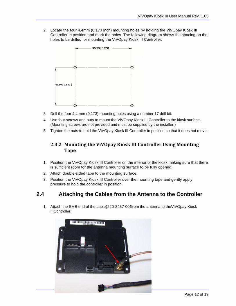
2. Locate the four 4.4mm (0.173 inch) mounting holes by holding the ViVOpay Kiosk III Controller in position and mark the holes. The following diagram shows the spacing on the holes to be drilled for mounting the ViVOpay Kiosk III Controller.
3. Drill the four 4.4 mm (0.173) mounting holes using a number 17 drill bit.
4. Use four screws and nuts to mount the ViVOpay Kiosk III Controller to the kiosk surface. (Mounting screws are not provided and must be supplied by the installer.)
5. Tighten the nuts to hold the ViVOpay Kiosk III Controller in position so that it does not move.
2.3.2 MountingtheViVOpayKioskIIIControllerUsingMountingTape
1. Position the ViVOpay Kiosk III Controller on the interior of the kiosk making sure that there
is sufficient room for the antenna mounting surface to be fully opened.
2. Attach double-sided tape to the mounting surface.
3. Position the ViVOpay Kiosk III Controller over the mounting tape and gently apply pressure to hold the controller in position.
2.4 Attaching the Cables from the Antenna to the Controller
1. Attach the SMB end of the cable(220-2457-00)from the antenna to theViVOpay Kiosk IIIController.

ViVOpay Kiosk III User Manual Rev. 1.05
Page 13 of 19
2. Attach the other end of the cable (220-2457-00) from the antenna to the ViVOpay Kiosk III Controller.
Note: Verify that the polarizing lug on the end of the data cable is facing towards the top of the ViVOpay Kiosk III Controller (away from the mounting plate) before inserting the cable. If the cable is installed incorrectly (upside-down), it will apply the wrong polarity to the LEDs and damage them.
2.5 Connecting to Power The KIOSK III can be powered through the serial communications port or the two-socket power connector. If you are using USB data communications, you must power the KIOSK III though the two-socket power connector. Connect +7.5 to 45VDC to the white two-socket Molex connector (mating connector Molex P/N 0039012020 with 5556-series crimps) or to pins 1 and 2 of the RS-232 connector (see next section).
Pin 1 - +7.5v to 45VDC
Pin 2 - Ground

ViVOpay Kiosk III User Manual Rev. 1.05
2.6 Connecting to the Data Port The Kiosk III has two data connections options: USB through the USB connector and RS-232 through the 14-pin Molex connector.
USB Port RS-232 Port
The USB port uses a standard USB connector and pinouts. The RS-232 port has the following pinouts. Pin Description Pin Description
1 Power ground 2 +7.5v to 45VDC
3 Power ground 4 +7.5v to 45VDC
5 No connection 6 Reserved
7 Reserved 8 Reserved
9 Signal ground 10 Signal ground
11 RS-232 Tx 12 RS-232 Rx
13 No connection 14 Reserved
To build your own RS-232 cable, use Molex female connector part number 0511101451 with 50394-series crimps (see www.molex.com for more information). Pin 1 is indicated by a triangle (diagram is socket-side view of female connector). If you are powering the Kiosk III from this connector, wire the two power pins (pins 2 and 4) together and the two power ground pins together (pins 1 and 3).
Page 14 of 19

ViVOpay Kiosk III User Manual Rev. 1.05
2.7 Using the ViVOpay Kiosk III to Make a Purchase
2.7.1 PresentingCards,Fobs,orNFCPhones
Your new ViVOpayKiosk III allows for credit/debit card purchases using the new contactless technology.
Present the card/fob/phone in close proximity to the front portion of the antenna module. Present the card/fob/phone so that maximum surface area is parallel to the antenna module as shown below. The antenna should beep and all four green LEDs should illuminate briefly to indicate a successful test.
This tests the antenna's ability to read the RFID test card. If unsuccessful, there will be no reaction from the reader. If you use a test card and the ViVOpay reader is attached to theViVOpay Kiosk III Controller, a dummy transaction can be tested. The transaction will not be authorized and will come back with a response, but will at least test for end-to-end connectivity.
2.7.2 MakingaPurchase
1. After the transaction has been entered on the kiosk control panel, the customer should present their card/fob/phone in close proximity so that maximum surface area is parallel to the antenna.
• A single beep and all four LEDs briefly flashing indicates the card/fob/phone has been read correctly.
3. Installation Points The ViVOpay Kiosk III is designed to be mounted on a metal surface and in close proximity to
any internal motors and electrical devices that may be operating inside the kiosk.However, the ViVOpayKiosk III is susceptible to RF and electromagnetic interference. It is important that the unit not be mountednear (within 3 or 4 feet) large electric motors, computer UPS systems, microwave transmitters, anti-theft devices, radio transmitters, communications equipment and so on.
Close proximity of metal to the RF-emitting end of the antenna can greatly reduce the range of the antenna. See the precautions described in Flush Mounting the Kiosk III Antenna.
Page 15 of 19

ViVOpay Kiosk III User Manual Rev. 1.05
Tie all cables neatly with nylon cable-ties and route them so that they are inaccessible and invisible to customers. Label the cable ends, host, ViVOpay and power, to simplify connection testing or component replacement.
Test the ViVOpayKiosk III installation using a test card to perform an end-to-end transaction (the same as an actual purchase on the Kiosk). The kiosk control panel should display "Requesting Authorization". Even if the transaction is declined (as it should be with a test card), it will prove connectivity all the way through the system. If possible the store manager or some other responsible party should test each ViVOpayKiosk III on a regular basis (perhaps at the start of each day or at least once per week) with a test card to ensure continued operation and functionality. If the kiosk is rebooted on a regular basis (such as every night) it is important to test the contactless reader as soon as possible afterwards to ensure continued communication to the kiosk.
Refer to the troubleshooting section of this manual before contacting your distributor with support questions.
4. RF Interference
Q. Why do I need to know about RF interference?
A. Contactless payment uses radio frequency technology to send card data to a contactless terminal reader.
Q. How can RF interference affect contactless payment?
A. RF interference can cause data errors. If RF interference is present, contactless payment devices may operate intermittently or inconsistently.
Q. Where does RF interference come from?
A. Radio frequency interference (RFI) can originate from a wide number of sources at the point-of-sale (POS). Some examples of sources of RF energy and RF interference include:
AM/FM radio and TV transmitters 2-way radios, pagers Mobile telephones Power lines, transformers Medical equipment Microwaves Electromechanical switches
Q. What should I do if I suspect RF interference exists in my environment?
A. Begin by inspecting your environment for possible sources of RF interference.
Q. Do equipment manufacturers test their devices for RF interference?
A. Electronic equipment is tested for RFI sensitivity by the manufacturers. These tests are performed in a controlled laboratory environment and will often not replicate the types of devices that would be encountered in your point-of-sale (POS) environment.
Q. What RF levels will impact RF operations?
A. Factors that can cause RF interference vary case-by-case. There are no set rules defining a single RF level that will cause RFI. RFI depends on the sensitivity of the equipment under consideration, or how low an interpreting signal can be in the presence of the equipment and cause problems.
Equipment can be particularly sensitive to very low signal levels of one frequency and yet be quite immune to high signal levels of another frequency - so frequency is an important factor.
Page 16 of 19

ViVOpay Kiosk III User Manual Rev. 1.05
Some electronic system components are internally shielded and have a very high immunity to interference; but generally, most equipment has not been so engineered.
5. Troubleshooting The ViVOpay Kiosk III readers are reliable and easy to troubleshoot. The components that may require troubleshooting include the power module (if applicable), the reader, and the serial cable.
Symptom Possible Cause Remedy
General Issues
Reader does not appear to be powered on (no LEDs lit).
Reader not powered on or incorrect voltage.
Improper use of internal power supply provided by the kiosk.
Check cable connections.
Verify that power is on and correct voltage and current are present.
Make sure that the correct pins are utilized.
Make sure that the power provided is within the specified range of the Kiosk III reader.
Make sure that the correct polarity is observed.
For more information, refer to the Input Voltage under the Electrical specification section.
Replace the ViVOpay Kiosk III.
Reading Cards/Fobs/Phones
LEDs do not light and beeper is not audible when card/fob presented.
Card/fob/phone not properly presented.
RF interference.
Unsupported card used.
Wrong firmware (contact your local support representative).
Present card/fob/phone closer to the antenna, and ensure it is parallel to the face of the reader.
Verify that the card/fob/phone is valid/current.
Verify that metal is not interfering with the antenna.
Test with “ViVOcard Contactless Test Card” part number 241-0015-03 Rev A.
Try a different card/fob.
Check to see if card/fob is damaged.
Verify that correct firmware is loaded on reader (local support representative only).
Power cable plug is fully inserted.
Replace the ViVOpay Kiosk III.
Page 17 of 19

ViVOpay Kiosk III User Manual Rev. 1.05
Some cards/fobs read, but not all.
Possible bad card/fob.
Unsupported card used.
Wrong firmware (contact your local support representative).
Check to see if card/fob is damaged.
Verify that correct firmware is loaded on reader (local support representative only).
Communication to Kiosk
No data is received, or data is garbled.
Faulty or incorrect cable connections.
Check that the cable connection is secure and in the correct port on the kiosk III.
Load Firmware
Firmware loading software indicate “ open RS232 failed”
Device is not well connected to PC. Or other software is using serial interface
Check the cable connection
Close other software which is using serial interface
Firmware loading software indicate “Load firmware failed”
Device is not well connected to PC
Check the cable connection
Firmware loading software indicate “Send Command failed”
Bootloader firmware in device is destroyed
contact your local support representative to reload manufacture firmware
If you are unable to resolve the problem, contact your local support representative.
6. Firmware Upgrade The Kiosk III can be upgraded using either the serial or USB interfaces.
6.1PreparationTo update the new firmware you will need:
• PC with available serial or USB port
• Kiosk III with a serial data cable or a USB cable attached
• For serial downloads: 220-1275-00 Download Dongle (DB-9 serial to RJ45)
• KIOSKIII firmware update software
• Firmware file for the desired firmware
• Power supply for the reader (7.5 – 45 VDC; 3 Watts output)
6.2 Load the ViVOpay Kiosk Firmware 1. Copy the Kiosk III software and firmware on the PC.
Page 18 of 19
ViVOpay Kiosk III User Manual Rev. 1.05
2. Connect the download dongle (220-1275-00) to the PC COM port and plug in the 220-2374-00 cable from Kiosk III to the dongle. Or connect the KIOSKIII to the PC using a USB cable.
3. Connect the power to the reader. There should be no beep, and no LED activity.
4. Launch the Kiosk III firmware update
5. Select the interface (COM or HID for USB).
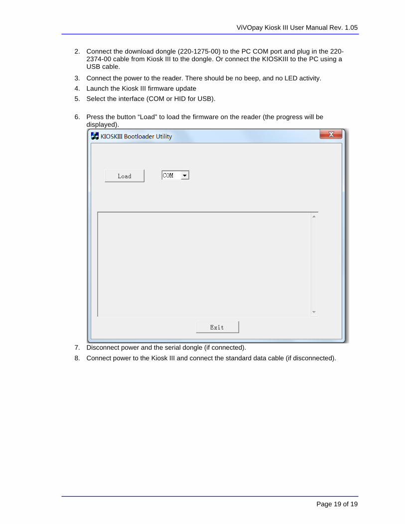
6. Press the button “Load” to load the firmware on the reader (the progress will be displayed).
7. Disconnect power and the serial dongle (if connected).
8. Connect power to the Kiosk III and connect the standard data cable (if disconnected).
Page 19 of 19