Visualizing the invisible: the construction of three low...
11
IOP PUBLISHING EUROPEAN JOURNAL OF PHYSICS Eur. J. Phys. 29 (2008) 607–617 doi:10.1088/0143-0807/29/3/020 Visualizing the invisible: the construction of three low-cost schlieren imaging systems for the undergraduate laboratory Venkatesh Gopal 1 , Julian L Klosowiak 1 , Robert Jaeger 2 , Timur Selimkhanov 1 and Mitra J Z Hartmann 1,3 1 Department of Biomedical Engineering, Northwestern University, Evanston IL 60208, USA 2 Iowa State University, Ames, IA 50011, USA 3 Department of Mechanical Engineering, Northwestern University, Evanston IL 60208, USA Received 20 November 2007, in final form 31 March 2008 Published 29 April 2008 Online at stacks.iop.org/EJP/29/607 Abstract We describe the construction and operation of three low-cost schlieren imaging systems that can be fabricated using surplus optics and 80/20, an aluminium extrusion based construction system. Each system has a different optical configuration. The low cost and ease of construction makes these systems highly suitable for high-school and undergraduate laboratories. Undergraduate students responded enthusiastically to the experience of assembling and operating these systems. This experience also served as an introduction to issues in optical design, helping the students gain an intuition for geometrical optics. (Some figures in this article are in colour only in the electronic version) 1. Introduction Schlieren imaging is a technique used to visualize variations in the optical density of a medium. It is a research tool as well as a popular demonstration experiment. In an undergraduate laboratory course, it can form the basis for a number of elegant experiments of varying degrees of sophistication [1–13]. Our aim in writing this paper is twofold. First, we describe the construction of three low-cost schlieren imaging systems, including custom-built optical mounts, that were made using 80/20, a modular aluminium framing system [14]. Second, we describe their potential for use as demonstration experiments in a high-school or undergraduate science laboratory. Our laboratory typically employs a large number of undergraduates each year who assist in almost all of the experimental projects being carried out [15]. Assigned to this project were 0143-0807/08/030607+11$30.00 c 2008 IOP Publishing Ltd Printed in the UK 607
Transcript of Visualizing the invisible: the construction of three low...

IOP PUBLISHING EUROPEAN JOURNAL OF PHYSICS
Eur. J. Phys. 29 (2008) 607–617 doi:10.1088/0143-0807/29/3/020
Visualizing the invisible: theconstruction of three low-costschlieren imaging systems for theundergraduate laboratory
Venkatesh Gopal1, Julian L Klosowiak1, Robert Jaeger2,Timur Selimkhanov1 and Mitra J Z Hartmann1,3
1 Department of Biomedical Engineering, Northwestern University, Evanston IL 60208, USA2 Iowa State University, Ames, IA 50011, USA3 Department of Mechanical Engineering, Northwestern University, Evanston IL 60208, USA
Received 20 November 2007, in final form 31 March 2008Published 29 April 2008Online at stacks.iop.org/EJP/29/607
AbstractWe describe the construction and operation of three low-cost schlieren imagingsystems that can be fabricated using surplus optics and 80/20, an aluminiumextrusion based construction system. Each system has a different opticalconfiguration. The low cost and ease of construction makes these systemshighly suitable for high-school and undergraduate laboratories. Undergraduatestudents responded enthusiastically to the experience of assembling andoperating these systems. This experience also served as an introduction toissues in optical design, helping the students gain an intuition for geometricaloptics.
(Some figures in this article are in colour only in the electronic version)
1. Introduction
Schlieren imaging is a technique used to visualize variations in the optical density of a medium.It is a research tool as well as a popular demonstration experiment. In an undergraduatelaboratory course, it can form the basis for a number of elegant experiments of varyingdegrees of sophistication [1–13]. Our aim in writing this paper is twofold. First, we describethe construction of three low-cost schlieren imaging systems, including custom-built opticalmounts, that were made using 80/20, a modular aluminium framing system [14]. Second, wedescribe their potential for use as demonstration experiments in a high-school or undergraduatescience laboratory.
Our laboratory typically employs a large number of undergraduates each year who assistin almost all of the experimental projects being carried out [15]. Assigned to this project were
0143-0807/08/030607+11$30.00 c© 2008 IOP Publishing Ltd Printed in the UK 607

608 V Gopal et al
two undergraduates (JK and TS, a final year and a third year undergraduate, respectively),and a recent high-school graduate (RJ), who spent a summer working on this project. Two ofthe three students had little prior experience conducting independent research. We (VG andMJZH) found that students responded enthusiastically to participating in a real and open-endedresearch project where ‘the answers’ were not known to any of us. The experience highlightedthe strong positive effect that working on a real-world research problem can have on studentswho are just beginning their study of science.
The work was motivated by our laboratory’s efforts to understand how mammals,specifically rats, track odour plumes to their source. This is important both from the pointof view of fundamental biology, and also for the design of biologically inspired odour sourcelocating robots that can be used for hazardous tasks such as locating chemical leaks or detectingland mines. We aimed to observe with high speed video cameras how rats sniffed at an odourplume and located its source. One way to visualize an odour plume is to seed the flow withsmall particles that scatter light and thus make the flow visible [16]. However, this techniquehas two drawbacks. First, it requires expensive laser sources to generate the laser light sheetthat scatters off the seed particles. Second, because the particles provide the animals withvisual cues, the search is no longer purely olfactory. Therefore, we decided instead to useschlieren imaging to view the path of the odour plume. By embedding the odourant in a gassuch as helium or carbon dioxide, which have refractive indices that are different from air, theodour plume can be imaged without providing visual cues to the animal.
2. Background
Schlieren effects are familiar to us all; we have all seen shimmering mirages on a hot road, orthe optical distortions caused by the hot air emerging from an aircraft jet engine. The wordschliere (plural schlieren) comes from Old German, where it means bits or pieces. In optics, aschliere is a region where the refractive index is different from that of the surrounding medium,causing the light ‘rays’ passing through that region to be refracted.
In 1665 Robert Hooke made the first known study of these refractive index variations. Inhis book Micrographia [17] Hooke set down in observation LVIII his study of such phenomena,and his conclusions that ‘the true cause of all these phenomena is from the inflection, ormultiplicate refraction of those rays of light’ that are passing through ‘a medium whose partsare unequally dense.’ However, schlieren imaging as it is practised today is based largely onthe techniques first invented by the German physicist August Toepler [18].
Since the time of Hooke’s observations, schlieren imaging has evolved into a precisiontool for visualizing variations in optical density, especially in fluid flows, and is applicablein any situation where the flow is accompanied by a change in refractive index. With someimagination, many flow fields can be manipulated to make them amenable to schlieren imaging[19]4.
3. 80/20—the industrial erector set
80/20 is the brand name of an extremely versatile and fairly inexpensive system of aluminiumextrusions. These extrusions can be joined to one another in different ways with a variety ofconnectors called joining plates. This flexibility allows the user to be imaginative and construct
4 This book is encyclopædic in its description of schlieren imaging and is easily the most comprehensive referenceavailable, with a vast bibliography. For the schlieren researcher or hobbyist, there is no better book to begin with.The book also contains a very large number of schlieren images of various phenomena, illustrating the versatility ofthe technique.

Low-cost schlieren imaging systems for undergraduate laboratories 609
Figure 1. 80/20 assembly. Figure demonstrates how 10 series T slotted rods are connected to a‘joining plate’. Rods are classified according to their cross-sectional area. A 1010 (1 × 1 inch2)and 1020 (1 × 2 inch2) rod are shown.
a number of fairly precise and extremely rugged structures. The 80/20 product range consistsof four different ‘series’ of components [14], but for our apparatus, the 10 series was morethan adequate.
Figure 1 shows two examples of 10 series extrusions along with a 90◦ joining plate,and demonstrates how 80/20 components are connected together. The extrusions within aseries are labelled according to their cross-sectional areas, with 12 different cross-sectionsavailable in the 10 series. The figure shows examples of a 1010 and a 1020 extrusion fromthe 10 series. 1010 denotes a rod with a 1 inch2 cross-sectional area (shown on the right inthe figure), while 1020 is a 1× 2 inch2 cross-section. We have found the 10 series rangeto be ideally suited to building many simple optical mounts and assemblies. The 10 seriescomponents have the added advantage that their bolt-hole spacing is compatible with that ofthe standard 1 inch spacing found on optical tables. Thus, 10 series assemblies can easilybe combined with existing experiments.
4. Some optical components
Basic optical components, even simple lens and mirror mounts, are often expensive. Theoptical mounts we constructed were built to hold large, non-standard size mirrors and lenses,and cost considerably less than commercially available parts of the same size. The onlymachining required was to cut the 80/20 rods to size. Table 1 provides a list of parts used toconstruct these components.
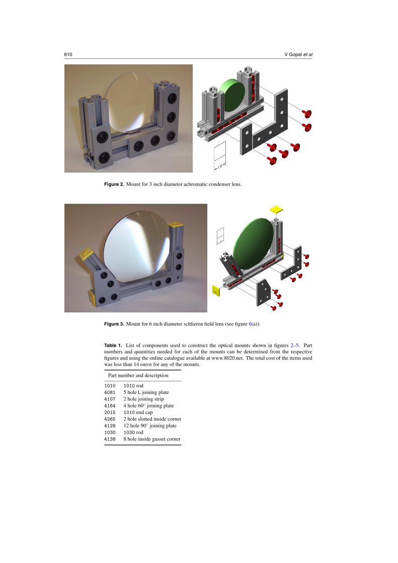
Figures 2 and 3 show lens mounts for a 3 inch diameter achromatic lens and a 6 inchdiameter plano-convex lens respectively, along with exploded views to demonstrate how thecomponents are assembled. Both these lenses are non-standard sizes for which commerciallymanufactured mounts are difficult to find. The ends of the extrusions can also be covered with‘end caps’, the yellow covers seen in figure 3, which add a professional finish.
Figure 4 shows front and back views of a mount for a 4.5 inch diameter concave mirroralong with an exploded view. With some machining, more complicated kinematic mounts
610 V Gopal et al
Figure 2. Mount for 3 inch diameter achromatic condenser lens.
Figure 3. Mount for 6 inch diameter schlieren field lens (see figure 6(a)).
Table 1. List of components used to construct the optical mounts shown in figures 2–5. Partnumbers and quantities needed for each of the mounts can be determined from the respectivefigures and using the online catalogue available at www.8020.net. The total cost of the items usedwas less than 14 euros for any of the mounts.
Part number and description
1010 1010 rod4081 5 hole L joining plate4107 2 hole joining strip4164 4 hole 60◦ joining plate2015 1010 end cap4265 2 hole slotted inside corner4128 12 hole 90◦ joining plate1030 1030 rod4138 8 hole inside gusset corner

Low-cost schlieren imaging systems for undergraduate laboratories 611
Figure 4. Front and back views of mount for 4.5 inch diameter mirror. Small pieces of soft rubberare used to cushion the mirror at the three points where it is held by the mount.
Figure 5. A simple mount for a lamp and a filter holder. The filter is a square, 2 inches on a side.
capable of tilting about multiple axes can be made. We did not attempt this, but helpful hintscan be found in the excellent paper by Quericoli et al [20].
Figure 5 shows a photograph of a holder for a projection lamp (the light source for theschlieren system), and a simple filter holder. The entire schlieren system was set up on a long1030 rod, which can easily be used as an optical bench (figure 7).
In all these figures, the essential simplicity of the 80/20 system can clearly be seen. Noneof these components takes more than 10 min to assemble, once the design is decided upon.To save time, we found it convenient to have a ‘toy-chest’ of commonly used 80/20 parts andextrusions always on hand to rapidly try out new designs and ideas.
Finally, we note that the large optical mounts described in this section may be particularlyuseful for demonstration experiments. Demonstration experiments must be large in sizebecause they are viewed by many students at the same time, but do not generally requireprecision tolerances. The 80/20 system provides an easy, low-cost method to construct thesetypes of large optical mounts.

612 V Gopal et al
(a)
(b)
(c)
Figure 6. Schlieren imaging configurations: (a) a two-lens, in-line system, (b) a two-mirror, Z-typesystem and (c) a single mirror system. The test region is shown hatched in all figures. Typical raypaths imaged by the camera are shown in red.
5. Three different schlieren imaging systems
Three schlieren imaging systems were constructed, each with a different optical configuration,which are shown in figure 6. Images were captured by a low-cost, 8-bit CCD camera
Low-cost schlieren imaging systems for undergraduate laboratories 613
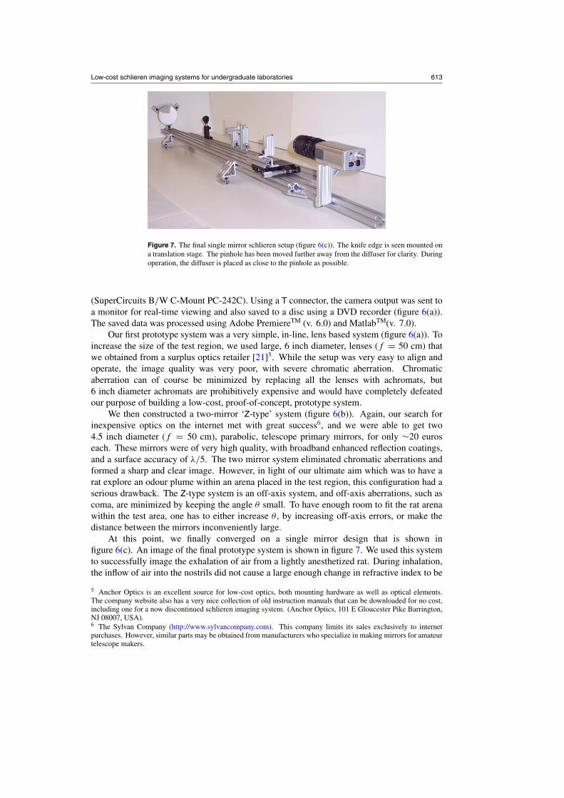
Figure 7. The final single mirror schlieren setup (figure 6(c)). The knife edge is seen mounted ona translation stage. The pinhole has been moved further away from the diffuser for clarity. Duringoperation, the diffuser is placed as close to the pinhole as possible.
(SuperCircuits B/W C-Mount PC-242C). Using a T connector, the camera output was sent toa monitor for real-time viewing and also saved to a disc using a DVD recorder (figure 6(a)).The saved data was processed using Adobe PremiereTM (v. 6.0) and MatlabTM(v. 7.0).
Our first prototype system was a very simple, in-line, lens based system (figure 6(a)). Toincrease the size of the test region, we used large, 6 inch diameter, lenses (f = 50 cm) thatwe obtained from a surplus optics retailer [21]5. While the setup was very easy to align andoperate, the image quality was very poor, with severe chromatic aberration. Chromaticaberration can of course be minimized by replacing all the lenses with achromats, but6 inch diameter achromats are prohibitively expensive and would have completely defeatedour purpose of building a low-cost, proof-of-concept, prototype system.
We then constructed a two-mirror ‘Z-type’ system (figure 6(b)). Again, our search forinexpensive optics on the internet met with great success6, and we were able to get two4.5 inch diameter (f = 50 cm), parabolic, telescope primary mirrors, for only ∼20 euroseach. These mirrors were of very high quality, with broadband enhanced reflection coatings,and a surface accuracy of λ/5. The two mirror system eliminated chromatic aberrations andformed a sharp and clear image. However, in light of our ultimate aim which was to have arat explore an odour plume within an arena placed in the test region, this configuration had aserious drawback. The Z-type system is an off-axis system, and off-axis aberrations, such ascoma, are minimized by keeping the angle θ small. To have enough room to fit the rat arenawithin the test area, one has to either increase θ , by increasing off-axis errors, or make thedistance between the mirrors inconveniently large.
At this point, we finally converged on a single mirror design that is shown infigure 6(c). An image of the final prototype system is shown in figure 7. We used this systemto successfully image the exhalation of air from a lightly anesthetized rat. During inhalation,the inflow of air into the nostrils did not cause a large enough change in refractive index to be
5 Anchor Optics is an excellent source for low-cost optics, both mounting hardware as well as optical elements.The company website also has a very nice collection of old instruction manuals that can be downloaded for no cost,including one for a now discontinued schlieren imaging system. (Anchor Optics, 101 E Gloucester Pike Barrington,NJ 08007, USA).6 The Sylvan Company (http://www.sylvancompany.com). This company limits its sales exclusively to internetpurchases. However, similar parts may be obtained from manufacturers who specialize in making mirrors for amateurtelescope makers.

614 V Gopal et al
Figure 8. Schlieren image of air exhaled from a deeply anesthetized rat. The image was takenwith a single mirror schlieren system that used a 12 inch diameter mirror and a high speed camera(Photron Fastcam-1024PCI, 1 KHz frame rate). The slightly brighter semi-circular region in theimage is light reflected from a beam-splitter.
seen in the video recording. In contrast, exhalation could be clearly seen, most likely becauseof the moisture and warmth of the expelled air. The success of this prototype system convincedus to construct a larger, research grade imaging system, and figure 8 shows one video frameof data taken with this system that shows the air exhaled by a deeply anesthetized rat.
5.1. Alignment and operation
The alignment procedure for each of the three systems is quite similar and relativelystraightforward. Our light source, shown in figure 5, consisted of a 300 W projector bulbilluminating a 500 µm diameter pinhole (not shown in the figure). A 3 inch diameter, f =5 cm achromat (figure 2), was used to collect light from the bulb and focus it onto the pinhole.A small piece of ground glass was placed in front of the pinhole to uniformly illuminatethe aperture. Without the ground glass, the bulb filament is imaged instead, providing anon-uniform background to the schlieren images (see [19, p 174]).
To assemble a schlieren system, the mirrors or lenses are first arranged according to anyof the configurations shown in figure 6 and adjusted to form a clear and undistorted image ofthe pinhole on a screen or piece of white cardboard (for the mirror-based setups, θ � 5◦–10◦).The position of the screen sets the position of the knife-edge plane. The schlieren test objectthat is to be imaged is first placed in the test region and brought into focus by the CCD camera,and then removed.
At this point, the image acquired by the CCD camera should be a bright, uniformlyilluminated circle. If not, the camera position should be changed until this is the case. Theintensity of the lamp is then adjusted so that the brightness of the circle is roughly half waybetween being completely dark and saturating the camera. Now, the knife-edge is introducedinto the image plane and moved to cut-off half the image of the pinhole. Accurately positioningthe knife-edge is crucial to obtaining good schlieren images.
To obtain a uniform background, the knife-edge must be positioned exactly in the imageplane. When the knife-edge is initially placed to block the image of the source aperture,the intensity of the image on the monitor will change from bright to dark. If the knife-edgeis placed exactly in the image plane, the bright circle will turn dark almost uniformly. Ifthe knife edge lies outside the image plane, then a dark shadow will pass across the brightcircle from either one side or the other. The direction from which the shadow passes across

Low-cost schlieren imaging systems for undergraduate laboratories 615
Figure 9. Schlieren image of a jet of helium gas taken with the prototype single-mirror system(figures 6(c) and 7). The large dynamic range of the image and the low bit-depth of the camera(8 bits) causes many parts of the image to be saturated.
the image reverses itself as the position of the focal plane is crossed. Thus, by iteration, theposition where the circle turns uniformly dark can be found. A more detailed description ofthis procedure can be found in Settles’ book [19, p 180].
Once a uniform cutoff has been achieved, schlieren images should be easily visible. Wehave found that as we approach the cutoff, we begin to see air currents in the room quite clearly.Also, if the palm of the hand is placed facing upwards in the test region, convective plumesdue to body heat can be clearly seen. The sensitivity of the schlieren system increases withthe degree of cutoff, while the dynamic range decreases. Thus, depending on the magnitudeof �n, the refractive index difference between the test object and the background air, thecutoff must be accordingly adjusted. For example, ‘strong’ schlieren objects such as a burningcandle require cutting off a very small amount of the source, otherwise the intensity changesexceed the dynamic range of the system and saturate the image. Figure 9 shows an image ofa jet of helium gas. Because the range of �n was large, and our camera had only an 8-bitdynamic range, large parts of the image are saturated. Once the system has been aligned, avariety of schlieren objects can be imaged. Classic examples include breath from the nostrils,a hot soldering iron, vapours from an organic solvent (both heavier and lighter than air) andjets of helium and carbon dioxide gas.
6. Summary
Pedagogically, we found this work to be of interest for three reasons. First, setting up andusing the schlieren system helped the students working on the project gain an intuition forsimple ray-based geometrical optics. Schlieren images are visually striking and the dynamicnature of these images makes for a vivid demonstration of the principles of ray optics. Morequantitative explanations of the formation of schlieren images using the eikonal equation, oreven Fourier optics, can also be introduced at this point (see the appendices in [19]).
Second, constructing these systems provided an excellent setting in which to discusscommon issues in optical design, such as tradeoff, calculating a light budget, evaluating

616 V Gopal et al
different designs and so forth. For example, as discussed in the previous section, positioningthe cutoff depends on the magnitude of �n that will be observed. This tradeoff betweenresolution and dynamic range demonstrated how a ‘one-size-fits-all’ approach fails to work,and one needs a sound grasp of the physics of the situation to design a good experiment.
Third, and perhaps most importantly, the students were exposed to a research environmentwhich gave them a flavour of how real experiments are conducted. The students first clearlydefined a goal—to image airflow from a breathing rat. To achieve this goal, they constructedthree different prototype schlieren systems. Using these systems, they conducted preliminaryexperiments that allowed them to conclude that schlieren imaging was indeed a suitableexperimental technique to image respiratory airflow. Finally, by examining the experimentalconstraints, they were able to select one of the three experimental geometries as being bestsuited for the task. In work only mentioned in passing in this paper, the students then went onto design, construct and operate a research-grade schlieren imaging system. This also gave thestudents, all of whom were engineers, an experience of the typical engineering design cyclewhich begins with a design that is then tested on a prototype, and finally leads to a finishedproduct. That exposure to a research environment can be an exciting introduction to sciencefor undergraduates is by no means a new idea [25–29]; however, to watch it first hand is adeeply satisfying experience.
Acknowledgments
Funding for this work was provided by NSF awards IOB-0446391 and IIS-0613568 awardedto MJZH, and by two research undergraduate awards to JLK: the Northwestern Academic YearUndergraduate Research Grant in 2006, and the McCormick Corporate Partner UndergraduateResearch Grant in 2007.
References
[1] Stong C L and Settles G S 1971 Schlieren photography is used to study the flow of air around small objects Sci.Am. 224 118–24
[2] Settles G S 2006 High-speed imaging of shock waves, explosions and gunshots Am. Sci. 94 22–31 (also availableonline at http://www.mne.psu.edu/psgdl/publicationswebpage.html)
[3] The laboratory of Vandiver J K (Department of Mechanical Engineering, Massachusetts Institute of Technology,Cambridge, MA 02139 USA) has made an excellent gallery of high-speed schlieren photographs availableat http://web.mit.edu/Edgerton/www/schlieren.html
[4] Geisert T W 1984 A single mirror schlieren optical system Am. J. Phys. 52 467–8[5] Leming C W 1982 Simple schlieren optical system utilizing Schmidt–Cassegrain telescopes Am. J. Phys.
50 764–5[6] Mitra S C, Chaskar M R and Phadke S A 1981 Design and fabrication of a simple schlieren scope Am. J. Phys.
49 158–61[7] Connor J G Jr 1970 Schlieren recording system Am. J. Phys. 38 385–6[8] Mason C L 1961 Simple schlieren demonstration Am. J. Phys. 29 642–3[9] Fuhs A E 1959 Knife edge for a schlieren system Am. J. Phys. 27 365
[10] Olson G, Peterson R, Pulford B, Seaberg M, Stein K, Stelter C and Weber R 2006 The role of shock waves inexpansion tube accelerators Am. J. Phys. 74 1071–6
[11] Kang P and Young F C 1972 Diffraction of laser light by ultrasound in liquid Am. J. Phys. 40 697–704[12] Penner S S, Davidor W and Bien F 1970 Determination of interference patterns from laser produced schlieren
interferometry Am. J. Phys. 38 1413–5[13] Spenceley B J, Dakin P and Scott K F N 1965 Velocity of sound in air using schlieren techniques Am. J. Phys.
33 51–4[14] 8020 Inc., 1701 South 400 East Columbia City, IN 46725, USA (www.8020.net)[15] Sensory and Neural Systems Engineering Laboratory (SeNSE Lab), Departments of Biomedical and Mechanical
Engineering, Northwestern University, Evanston, IL 60208, USA (http://www.mech.northwestern.edu/hartmann/)

Low-cost schlieren imaging systems for undergraduate laboratories 617
[16] Porter J, Craven B, Khan R M, Chang S C, Kang I, Judkewicz B, Volpe J, Settles G S and Sobel N 2007Mechanisms of scent tracking in humans Nat. Neurosci. 10 27–9
[17] Hooke R 1665 Micrographia: or some physiological descriptions of minute bodies made by magnifying glasseswith observations and inquiries thereupon (London: John Martyn for the Royal Society)
[18] See reprints in Mayer-Arendt J R (ed) 1992 Selected Papers on Schlieren Optics (SPIE Milestone Series vol MS61) (Bellingham WA: SPIE Optical Engineering Press)
[19] Settles G S 2001 Schlieren and Shadowgraph Techniques: Visualizing Phenomena in Transparent Media (Berlin:Springer)
[20] Quercioli F, Tiribilli B, Mannoni A and Acciai S (Optomechanics with LEGO) 1998 Appl. Opt. 37 3408–16[21] Anchor Optics, http://www.anchoroptics.com/[22] Weinberg F J 1963 Optics of Flames A very comprehensive discussion of quantitative schlieren imaging of
flames. The level of mathematical sophistication is higher than that of Settle’s book. (London: Butterworths)[23] The list of references is too large to list here. A ‘keyword quick search’ using the search term undergraduate
on the American Journal of Physics website at http://scitation.aip.org/ajp/ will list a very large number ofrelevant papers. A few articles can also be found by searching the Institute of Physics online archive athttp://www.iop.org/EJ/search, with the search terms ‘undergraduate’ AND ‘education’ AND ‘teaching’.
[24] Breslin L 1974 A student’s view of undergraduate involvement in research Am. J. Phys. 42 948–51[25] Robinson M C 1979 Undergraduate laboratories in physics Am. J. Phys. 47 859–62[26] Ptak R L and Stoner R E 1972 A Physics survey course with a large entropy Am. J. Phys. 40 611–4[27] McGavern N G 1991 Guest comment: undergraduate research: a way of teaching and learning Am. J. Phys.
59 587–8