
Visualization- Determining Depth From Stereo Saurav Basu BITS Pilani 2002.
37
Visualization- Determining Depth From Stereo Saurav Basu BITS Pilani 2002
-
date post
22-Dec-2015 -
Category
Documents
-
view
220 -
download
0
Transcript of Visualization- Determining Depth From Stereo Saurav Basu BITS Pilani 2002.
Visualization-Determining Depth From Stereo
Saurav Basu
BITS Pilani
2002
Introduction
Example of Human Vision Perception of Depth from Left and right eye
images Difference in relative position of object in
left and right eyes. Depth information in the 2 views??
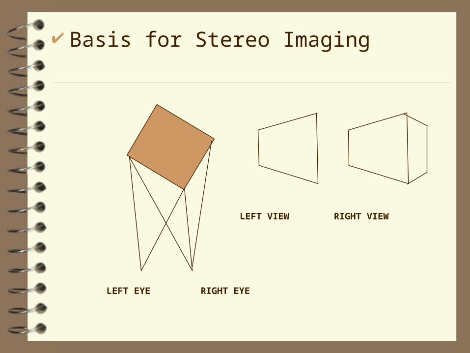
Basis for Stereo Imaging
LEFT EYE RIGHT EYE
LEFT VIEW RIGHT VIEW
The Stereo Problem
– The stereo problem is usually broken in to two subproblems• Extraction of Depth information from Stereo
Pairs• Use of depth data to visualize the world
scene in 3-dimensions by a suitable projection technique.
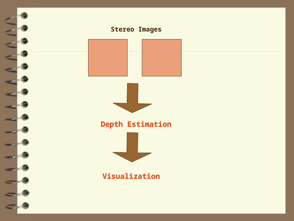
Stereo Images
Depth Estimation
Visualization
What are Stereo Images?
Images of the same world scene taken from slightly displaced view points are called stereo images.To illustrate how a typical stereo imaging system let us take a look at the camera model for obtaining stereo images
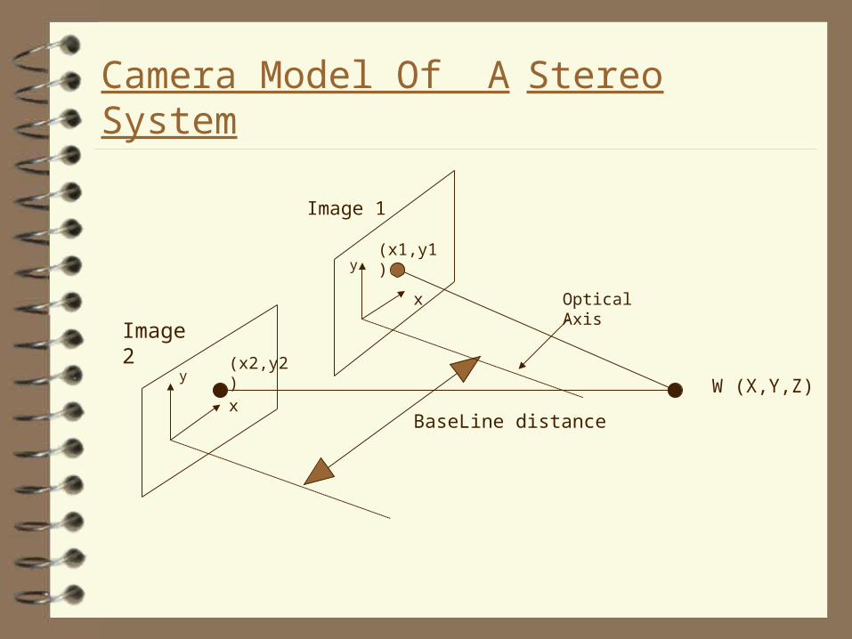
Camera Model Of A Stereo System
Image 2
Image 1
W (X,Y,Z)
BaseLine distance
y
x
x
y
(x2,y2)
(x1,y1)
Optical Axis
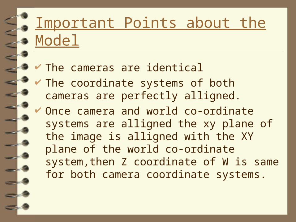
Important Points about the Model
The cameras are identical The coordinate systems of both cameras are
perfectly alligned. Once camera and world co-ordinate systems are
alligned the xy plane of the image is alligned with the XY plane of the world co-ordinate system,then Z coordinate of W is same for both camera coordinate systems.
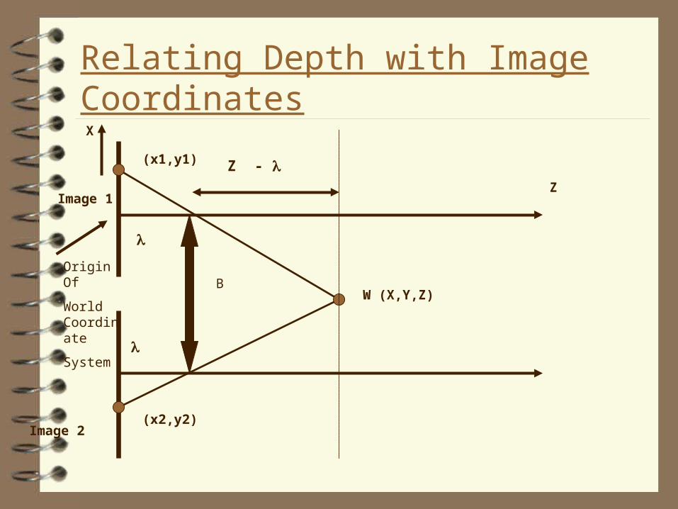
Relating Depth with Image Coordinates
Z
W (X,Y,Z)
X
Origin Of
World Coordinate
System
B
Image 2
Image 1
(x1,y1)
(x2,y2)
Z -
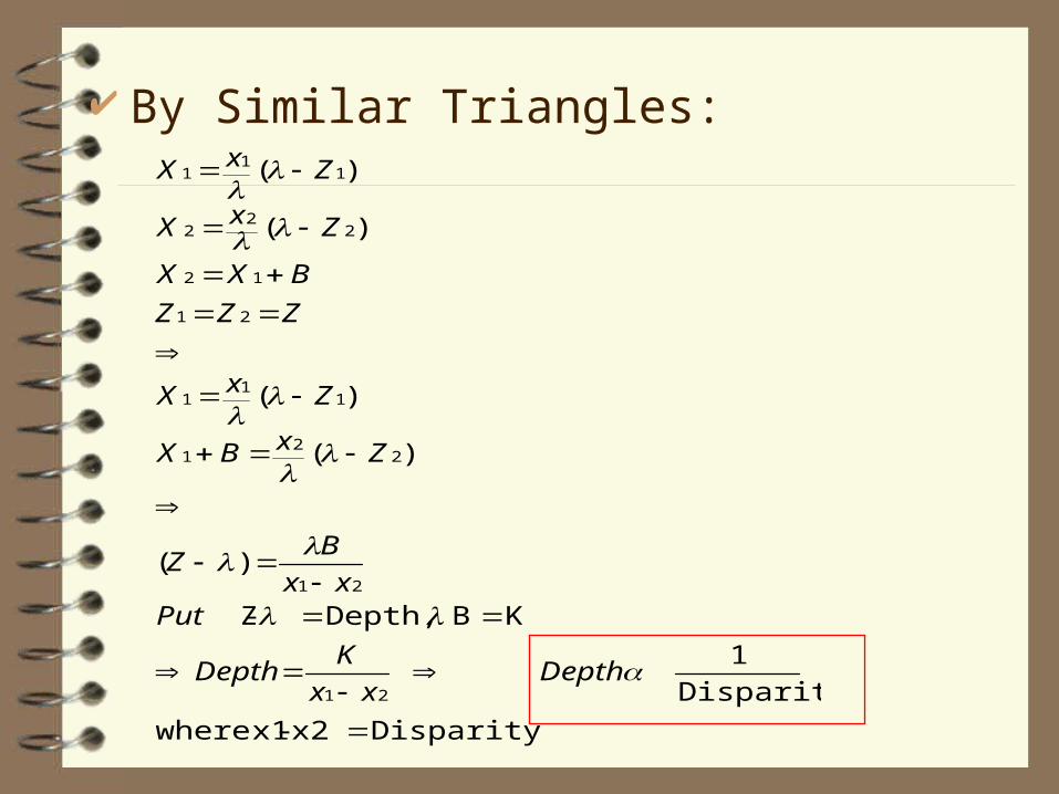
By Similar Triangles:
Disparity x2- x1where
Disparity
1
KB Depth, - Z
)(
)(
)(
)(
)(
21
21
22
1
11
1
21
12
22
2
11
1
Depthxx
KDepth
Putxx
BZ
ZxBX
ZxX
ZZZ
BXX
ZxX
ZxX
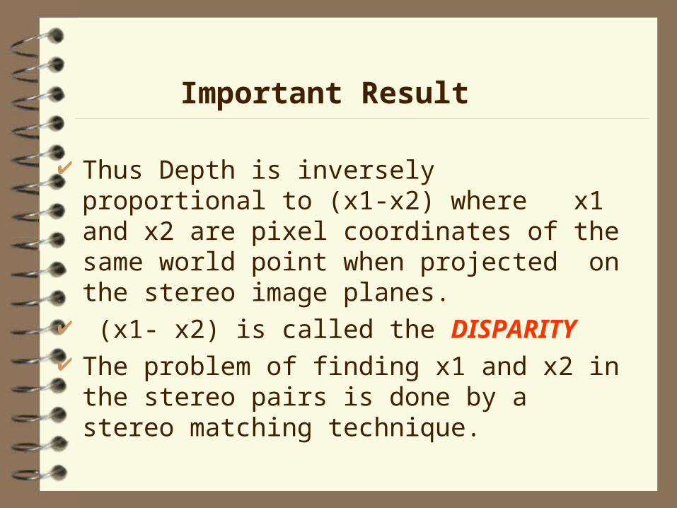
Thus Depth is inversely proportional to (x1-x2) where x1 and x2 are pixel coordinates of the same world point when projected on the stereo image planes.
(x1- x2) is called the DISPARITY The problem of finding x1 and x2 in the stereo
pairs is done by a stereo matching technique.
Important Result
Stereo Matching
– The goal of stereo matching algorithms is to find matching locations in the left and right images .
– Specifically find the coordinates of the pixel on the left and right images which correspond to the same world point.
– It is also called the correspondence problem.
Correlation based approaches
– A common approach to finding correspondences is to search for local regions that appear similar
– Try to match a window of pixels on the left image with a corresponding sized window on the right image.
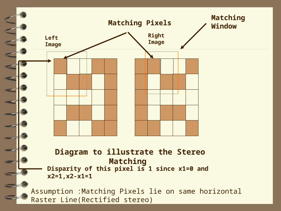
Matching PixelsMatching Window
Diagram to illustrate the Stereo Matching
Assumption :Matching Pixels lie on same horizontal Raster Line(Rectified stereo)
Disparity of this pixel is 1 since x1=0 and x2=1,x2-x1=1
Left Image Right Image
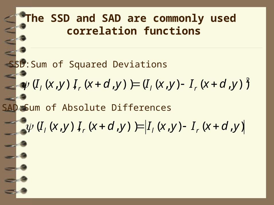
The SSD and SAD are commonly used correlation functions
2)),(),(()),(),,(( ydxIyxIydxIyxI rlrl
),(),()),(),,(( ydxIyxIydxIyxI rlrl
SSD:Sum of Squared Deviations
SAD:Sum of Absolute Differences
The Multi Window Algorithm
In this algorithm technique 9 different windows are used for calculating disparity of a single pixel.
The window which gives the maximum correlation is used for disparity calculations.
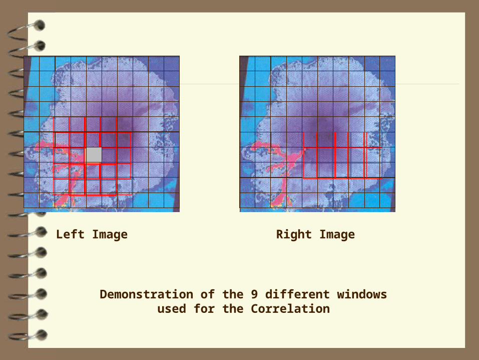
Left Image Right Image
Demonstration of the 9 different windows used for the Correlation
Disparity Map
Based on the calculated disparities a disparity map is obtained
The disparity map is a gray scale map where the intensity represents depth.
The lighter shades (greater disparities) represent regions with less depth as opposed to the darker regions which are further away from us.
Visualization
Visualization is the process by which I use the depth estimates from the stereo matching to build projections .
3-D information can be represented in many ways :
-Orthographic projections-Perspective Projections
Perspective Projections
Perspective projections allow a more realistic visualization of a world scene
The visual effect of perspective projections is similar to the human visual system and photographic systems.
Hence perspective projection of the 3-d data was implemented for the stereo pairs.
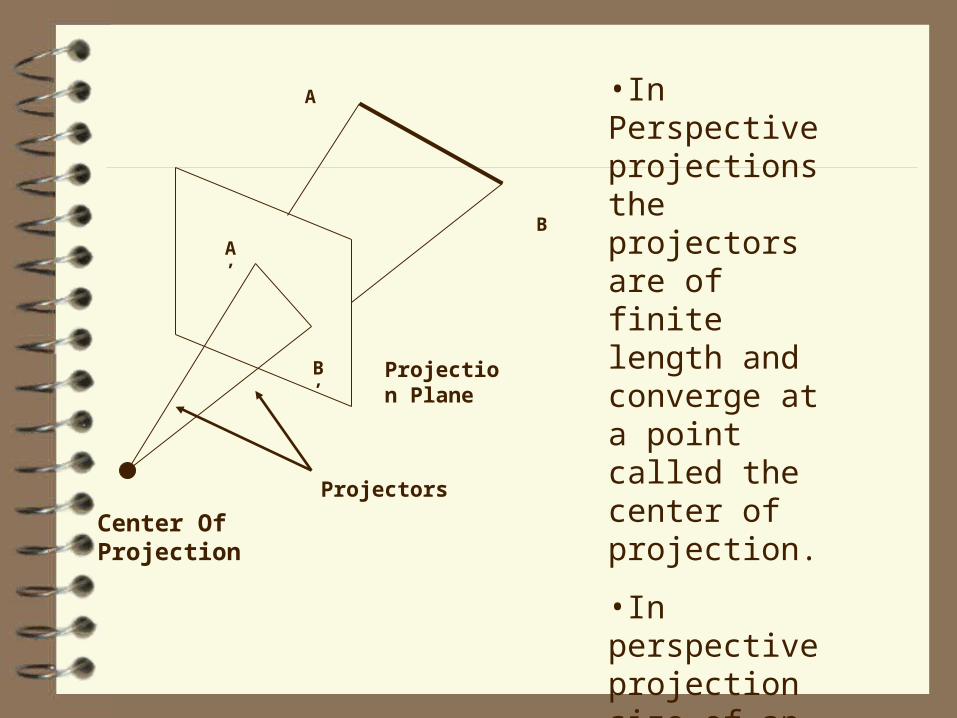
Center Of Projection
A
BA’
B’ Projection Plane
•In Perspective projections the projectors are of finite length and converge at a point called the center of projection.
•In perspective projection size of an object is inversely proportional to its distance from ooint of projection
Projectors
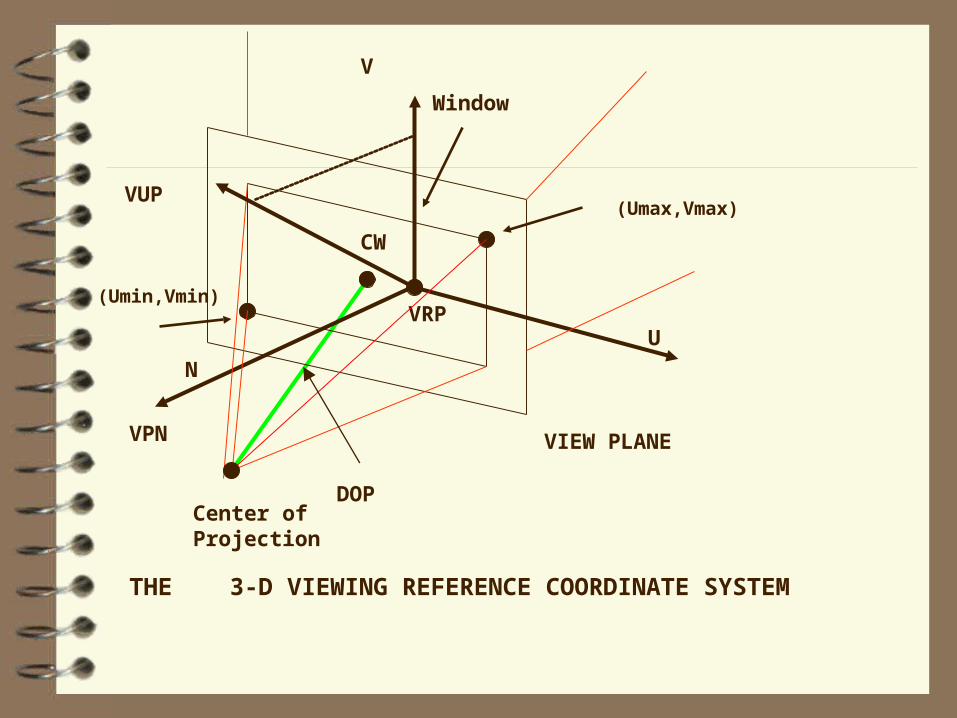
Specifying a 3-D View
To specify a 3-d view we need to specify a projection plane and a center of Projection:
The Projection plane specified by 1. A point on the plane called the
View Reference Point (VRP)2. The normal to the view plane,i.e. View Plane Normal (VPN)
We define a VRC (View Reference Coordinate system) on the projection plane with u,v,and n being its 3 axes forming a right handed coordinate system
The origin of the VRC system is the VRP The VPN defines the ‘n’ axis of the VRC system A View Up Vector (VUP) determines the ‘v’ axis of
the VRC system.The projection of the VUP parallel to the view plane is coincident with the ‘v’ axis.
The ‘u’ axis direction is defined such that the ‘u’,’v’ and ‘n’ form a right handed coordinate system. A view Window on the view plane is defined ,projections lying outside the view window are not displayed .The coordinates (Umin,Vmin) and (Umax,Vmax) define this window. The center of projection Projection reference point(PRP).
V
U
(Umin,Vmin)
(Umax,Vmax)
VPN
VRP
VIEW PLANE
Center of Projection
THE 3-D VIEWING REFERENCE COORDINATE SYSTEM
VUP
Window
N
CW
DOP
The semi infinite pyramid formed by the PRP and the projectors passing through the corners of the view window form a view volume.
A Canonical view volume is one where the VRC system is alligned with the World Coordinate system.
X or YBack Plane
Front Plane
-1
-1
1
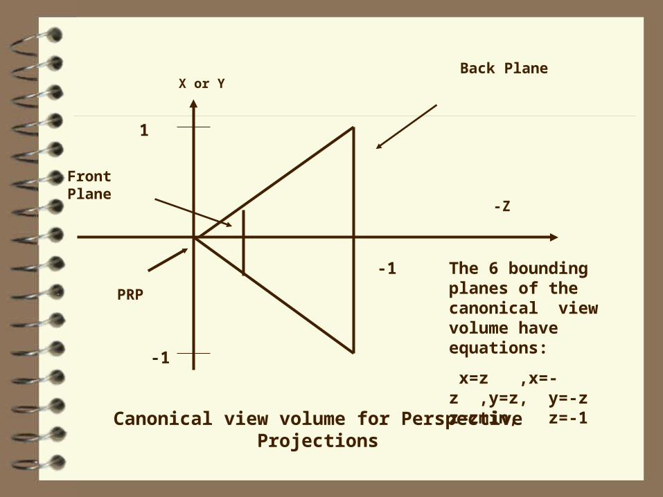
Canonical view volume for Perspective Projections
-Z
The 6 bounding planes of the canonical view volume have equations:
x=z ,x=-z ,y=z, y=-z z=zmin, z=-1
PRP
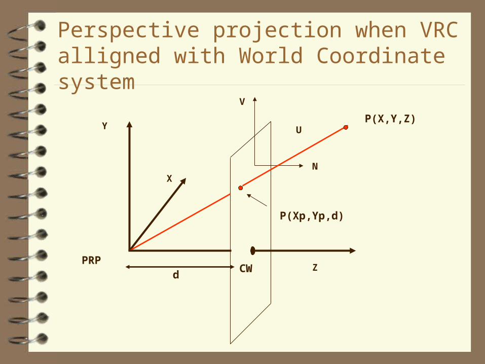
Perspective projection when VRC alligned with World Coordinate system
Y
Z
X
V
U
N
P(Xp,Yp,d)
P(X,Y,Z)
dPRP
CW
1] /
/
[] z [1
matrix a
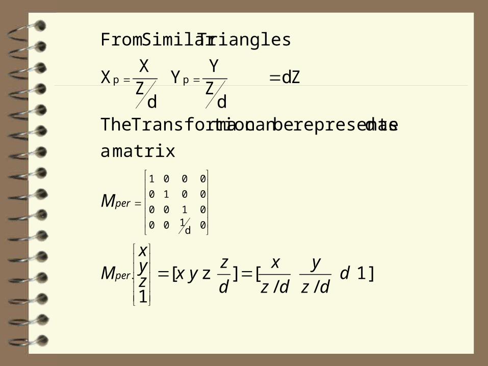
as drepresente becan tion Transforma The
d Z
dZY
Y
dZX
X
TrianglesSimilar From
.
0d100
0100
0010
0001
pp
ddz
y
dz
x
d
zyxz
yx
M
M
per
per
Only true when view volume is canonical For arbitrary view volume -
First transform the view volume intocanonical form and then apply the above formula to take projections
For transforming a view volume we do the following: 1)Translate VRP to origin
2)Rotate VRC to allign u,v and n axes with the X,Y and Z axes.
3)Translate the PRP to origin
4)Shear to make center line of view volume the the z-axis.
5)Scale such that the view volume becomes the canonical perspective view volume
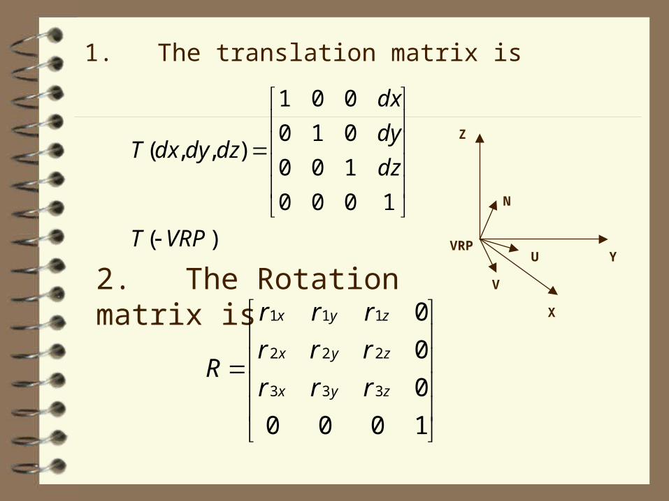
1. The translation matrix is
)(
1000
100
010
001
),,(
VRPT
dz
dy
dx
dzdydxT
2. The Rotation matrix is
1000
0
0
0
333
222
111
zyx
zyx
zyx
rrr
rrr
rrr
R
N
V
U
Z
X
YVRP
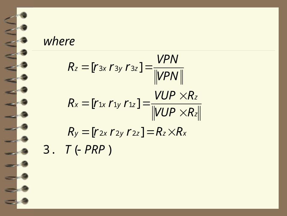
)( 3.
][
][
][
2 2 2
1 1 1
3 3 3
PRPT
RRrrrR
RVUP
RVUPrrrR
VPN
VPNrrrR
where
xzzyxy
z
zzyxx
zyxz
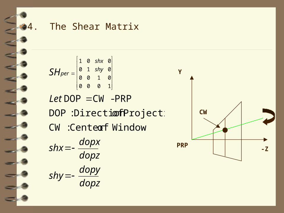
4. The Shear Matrix
dopz
dopyshy
dopz
dopxshx
Let
SH shy
shx
per
WindowofCenter :CW
Projection ofDirection :DOP
PRP-CWDOP
1000
0100
010
001
PRP
Y
-Z
CW
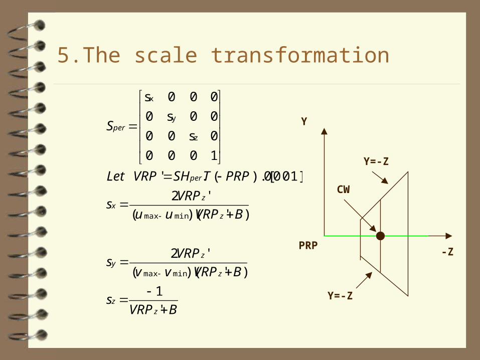
5.The scale transformation
BVRPs
BVRPvv
VRPs
BVRPuu
VRPs
PRPTSHVRPLet
S
zz
z
zy
z
zx
per
per
'
1
)')((
'2
)')((
'2
1] 0 0 0).[(.'
1000
0s00
00s0
000s
minmax
minmax
z
y
x
PRP
Y
-Z
CW
Y=-Z
Y=-Z
Once all the projected points have been calculated, scale the coordinates to fit the display screen.
A wire frame display of the image is obtained by joining the projections of all points lying on the same row or column.
Map the pixel colors of the image on to the projected points to create a realistic effect.
Limitations
Can work well only for stereo images whereminute details are not required.
More suited for depth estimation of landscape through images taken from top.
No accurate metric calculations done.


![SAURAV ADMIT CRD[2].docx](https://static.fdocuments.net/doc/165x107/55cf859c550346484b8fef55/saurav-admit-crd2docx.jpg)
