Visual and Audible Signaling Products For Harsh and ... · PDF fileVisual and Audible...
92
Visual and Audible Signaling Products For Harsh and Hazardous Areas MEDC ® Series Flex-Tone TM Series HAZARD•GARD TM Series Class I, Divsion 1, Groups A, B, C & D Class I, Divsion 2, Groups A, B, C & D Class I, Zone 2, Group IIC ATEX Ex II 1 GD, EExed IIC
Transcript of Visual and Audible Signaling Products For Harsh and ... · PDF fileVisual and Audible...

Visual and Audible Signaling Products For Harsh and Hazardous Areas
MEDC® Series Flex-ToneTM Series HAZARD•GARD TM SeriesClass I, Divsion 1, Groups A, B, C & DClass I, Divsion 2, Groups A, B, C & DClass I, Zone 2, Group IICATEX Ex II 1 GD, EExed IIC

Visual and Audible Signaling Devices For Harsh Hazardous Areas MEDC ® Series & HAZARD•GARD TM Series
Break Glass Fire Alarm Call Point—Hazardous LocationsBGCertifi cation ATEXUL Listed for: Class I, Div 2, Groups A,B,C,D Class I, Zone 2
Certifi ed Ambient Temperature -13°F to +131°F -25°C to +55°C
Ingress Protection NEMA 4X & 6 IP66 & 67
Material Corrosion-free GRP
Entries Up to 4 x ½" NPT
Weight 2.6lb/1.2kg
Options: Body color, certifi cation
Certifi cation Type Ordering Code Catalog # Standard Product Confi guration
UL Listed, Class I, Div 2, Groups A, B, C, D, Zone 2 Haz. Loc.
869101 BGUL4C6C1DSN7R Explosion protected, 2 x ½" NPT bottom entries, single break glass switch latching, painted red GRP fi nish
ATEX Ex II 1GD Intrinsically Safe 800002 BGIB4B6B1DSN6RExplosion protected, Zone 0, 1 & 2, DC, 2 x M20 bottom entries, single break glass switch latching, single switch, red fi nish
ATEX Ex II 2GD Increased Safety 800003 BGEB4B6B1DSN6RExplosion protected Ex II 2GD, EExed, IIC, T6, Zone 1 & 2, DC, 2 x M20 bottom entries, single break glass switch latching, red fi nish
2
How To Order■ For standard models listed in this catalog, use the Ordering code column and quantities that you need.
■ For non-standard models, reference the ordering requirements matrix at the end of each section to build a catalog number. Give this catalog number to customer service.
ModelType
Description of product, key certifi cation information & options
Standard model information—available ex-stock on same day dispatch (subject to stock levels)
How To Use This Catalog
Use this to order products listed in the catalog
Certifi cations for specifying
Ordering RequirementsOrdering RequirementsThe following code is designed to help in the selection of the correct unit. Build up the reference number by inserting the code for each component into the appropriate box.
Duty TagUnit Type Model Material Certifi cation Entries Label Label Features Finish
SM87 PBL N N N
Entries Code
20mm Left/Right 1L1R20mm Top/Bottom 1T1B20mm Bottom 1B25mm Left/Right 2L2R25mm Top/Bottom 2T2B25mm Bottom 2B½" NPT Left/Right 3L3R½" NPT Top/Bottom 3T3B½" NPT Bottom 3B¾" NPT Left/Right 4L4R¾" NPT Top/Bottom 4T4B¾" NPT Bottom 4B
Certifi cation Code
EExdIICT6 DUL Listed ULCSA Certifi ed C
*Material Code
Stainless Steel SAlloy A
Finish Code
Red RBlue BYellow YYellow/Black Stripes X
* UL version only available in Alloy.
Use the catalog # to reference model type and nameplate information
Use the ordering requirements to build the appropriate catalog number

Visual and Audible Signaling Devices as tough as your environment.
3
Manufacturing Areas
Waste Water Treatment
Food Processing Facilities
Paper and Pulp Operations
Pharmaceutical Manufacturing
Petrochemical Facilities
Applications Include:
Why Cooper Crouse-Hinds?■ The broadest line of harsh and hazardous
signaling, alarm and communication products available in both IEC and NEC designs and certifi cations.
■ A new line of hazardous area call points (fi re alarm or emergency notifi cation devices) provides you a unique product offering unequalled by any other manufacturer of hazardous location signaling products.
■ Worldwide listings with UL, cUL, ATEX, GOST, CSA and CQST (Chinese) approvals provide customer solutions that the competition can’t match.
■ Superior enclosure materials providing unmatched ingress protection and corrosion resistance from the harshest conditions.
■ A unique signaling product offering integral visual and audible signaling capability pre-wired for simultaneous output activation.
■ A new line of heat detectors for early indication of potential processing problems.
Visual and Audible Signaling Devices for Harsh Environments ........................ 2–9
MEDC® Series Fire Alarm or Emergency Call Points ..................................... 10–16
MEDC Series Status Lights ............................................................................. 17–20
Strobes, Rotating Beacons and Indicating Lights .......................................... 21–59
MEDC Series Strobe Lights ........................................................................... 22–34
Hazard Gard Series Strobes, Rotating Beacons and Indicating Lights ............... 35–38
Hazard Gard Fire Alarm ................................................................................ 39–40
Hazard Gard Strobe Lights ............................................................................ 41–43
Hazard Gard Rotating Beacons ...................................................................... 44–46
Steady-On Beacons ..............................................................................................47
MEDC Series Steady-On Beacons .................................................................. 48–56
Hazard Gard Steady-On Beacons ................................................................... 57–59
MEDC Series Visual and Audible Combo Units .............................................. 60–61
MEDC Series Speakers and Tone Generators ............................................... 62–73
Flex-Tone™ Series New Audible Products ........................................................ 74–79
MEDC Series Heat Detectors ......................................................................... 80–82
Diode Polarized Technology .................................................................................83
Fire Alarm Systems ........................................................................................ 84–85
Sound Basics ........................................................................................................86
Glossary and Explanations ...................................................................................87
Index ............................................................................................................... 88–91
Table of Contents

4
A Guide To The Use Of Electrical Equip mentIn Po ten tial ly Ex plo sive At mos pheresIntroductionPotentially explosive atmospheres exist where there is a risk of explosion due to mixtures of gas/air, vapor/air, dust/air or other flammable combinations. In such areas there is a necessity to eliminate sources of ignition such as sparks, hot surfaces or static electricity which may ignite these mixtures. Where electrical equipment has to be used in these areas it must be so designed and constructed as to not create sources of ignition capable of igniting these mixtures. Before electrical equipment can be used in a potentially explosive atmosphere, a representative sample has to be fully tested and certified by an independent authority such as Baseefa 2001 in Europe or UL in the U.S.A.
This information is intended as a guide only and further expert guidance should be sought before placing into service, maintaining or repairing any item of equipment in a potentially explosive atmosphere.
Where comparisons are shown between, for example, European and North American practice this may be an ap prox i ma tion and individual standards/codes of practice should be consulted for precise details.
Area Classifi cation Plants are divided into Zones (European and IEC method) or Divisions (North American method) ac cord ing to the likelihood of a potentially explosive atmosphere being present.Note: North American legislation now allows Zones to be used to classify areas, where this practice is used it follows the IEC Zone method.
European & IEC Classification Definition of zone or division North American Classification
Zone 0 (gases) An area in which an explosive mixture is Class I, Division 1 (gases)Zone 20 (dusts) continuously present or present for long periods Class II, Division 1 (dusts)
Zone 1 (gases) An area in which an explosive mixture is Class I, Division 1 (gases)Zone 21 (dusts) likely to occur in normal operation Class II, Division 1 (dusts)
Zone 2 (gases) An area in which an explosive mixture is not Class I, Division 2 (gases)Zone 22 (dusts) likely to occur in normal operation and if it Class II, Division 2 (dusts) occurs it will exist only for a short time Class III, Division 1 (fibers) Class III, Division 2 (fibers)
Gas Groups (plus dusts and fi bers)There are two main gas groups, Group I—Mining only and Group II—Surface IndustriesThese categories are used in European and I.E.C. groupings.
Group I is concerned only with underground mining where methane and coal dust are present.
Group II gases occurring in surface industries, are sub-grouped according to their volatility. This enables electrical equip ment to be designed to less onerous tolerances if it is to be used with the least volatile gases.
Typical gas/material European/I.E.C. Gas Group North American Gas Group
Methane I -Acetylene IIC AHydrogen IIC BEthylene IIB CPropane IIA DMetal dust - ECoal dust - FGrain dust - G

5
TemperatureHot surfaces can ignite explosive atmospheres. To guard against this, all elec tri cal equip ment intended for use in a potentially explosive atmosphere is classified according to the maximum surface temperature it will reach in service. This temperature is normally based on a surrounding ambient temperature of 40 degrees Centigrade (102 degrees Fahr en heit). This tem per a ture can then be compared to the ignition temperature of the gas(es) which may come into contact with the equipment and a judgement reached as to the suitability of the equipment to be used in that area.
Temperature Classification Maximum Surface Temperature European/I.E.C. North American T1 T1 450° C
T2 T2 300° C T2A 280° C T2B 260° C T2C 230° C T2D 215° C
T3 T3 200° C T3A 180° C T3B 165° C T3C 160° C
T4 T4 135° C T4A 120° C
T5 T5 100° C
T6 T6 85° C
e.g. Butane has an ignition temperature of 365 degrees Centigrade, equipment used in the vicinity of this gas would need a T rating of T2 or better.
Types of Electrical Equipment Suitable for use in Potentially Explosive At mos pheresDifferent techniques are used to prevent electrical equipment from igniting explosive atmospheres. There are restrictions on where these different types of equipment can be used as follows:
European
Area of useDesignation
Standard
IEC
Area of useDesignation
Standard
NEC
Area of useDesignation
Standard
Flameproof Enclosure—An enclosure used to house electrical equipment, which when subjected to an internal explosion will not ignite a surrounding explosive atmosphere.
Zones 1 & 2
EExdEN60079-1
Zones 1 & 2
ExdIEC60079-1
Class I
Divisions 1 & 2
–UL1203
Intrinsic Safety—A technique whereby electrical energy is limited such that any sparks or heat generated by electrical equipment is sufficiently low as to not ignite an explosive atmosphere.
Zones 0, 1 & 2
EExiEN50020
Zones 1 & 2
ExiIEC60079-11
Class I
Divisions 1 & 2
–UL913
Increased Safety—This equipment is so designed as to eliminate sparks and hot surfaces capable of igniting an explosive atmosphere.
Zones 1 & 2
EExeEN60079-7
Zones 1 & 2
ExiIEC60079-7
–––
Purged and Pressurized—Electrical equipment is housed in an enclosure which is initially purged to remove any explosive mixture, then pressurised to prevent ingress of the surrounding atmosphere prior to energization.
Zones 1 & 2
EExpEN50016
Zones 1 & 2
ExpIEC60079-2
Class I
Divisions 1 & 2
–NFPA496
Encapsulation—A method of exclusion of the explosive atmosphere by fully encapsulating the electrical components in an approved material.
Zones 1 & 2
EExmEN60079-18
Zones 1 & 2
ExmIEC60079-18
–––
Oil Immersion—The electrical components are immersed in oil, thus excluding the explosive atmosphere from any sparks or hot surfaces.
Zones 1 & 2
EExoEN50015
Zones 1 & 2
ExoIEC60079-6
Class I Division 2
–UL698
Powder Filling—Equipment is surrounded with a fine powder, such as quartz, which does not allow the surrounding atmosphere to come into contact with any sparks or hot surfaces.
Zones 1 & 2
EExqEN50017
Zones 1 & 2
ExqIEC60079-5
–
––
Non-sparking—Sparking contacts are sealed against ingress of the surrounding atmosphere, hot surfaces are eliminated.
Zone 2
EExnEN60079-15
Zone 2
ExnIEC60079-15
–
––

6
Selection, installation and maintenance of electrical equipment intended for use in po ten tial ly ex plo sive atmospheres.International and national standard requirements for the safe use of electrical equipment in po ten tial ly explosive atmospheres as follows:
International Europe U.S.A.
General Recommendations IEC60079-14 EN60079-14 N.E.C. Chapter 5Classification of Hazardous Areas IEC60079-10 EN60079-10 N.E.C. Chapter 5Inspection and Maintenance of Electrical Equipment IEC60079-17 EN60079-17 –Requirements for Flameproof Enclosures IEC60079-14 EN60079-14 N.E.C. Chapter 5Requirements for Intrinsically Safe Equipment IEC60079-14 EN60079-14 N.E.C. Chapter 5Requirements for Increased Safety Equipment IEC60079-14 EN60079-14 N.E.C. Chapter 5Requirements for Purged and Pressurized Equipment IEC60079-14 EN60079-14 N.E.C. Chapter 5Requirements for Non-Sparking Equipment IEC60079-14 EN60079-14 –
Cooper Crouse-Hinds advises that all Explosionproof electrical equipment is maintained, by suitably trained personnel, in accordance with the Man u fac tur ers’ recommendations.
Any spare parts used should be purchased from the original Manufacturer and repairs should be carried out by the Manufacturer or under his supervision, in order that the item remains in conformance with the certification documents.
The Certifi cation ProcessAll electrical equipment, intended for use in a potentially explosive atmosphere, should be certified as suitable for such use.
The methods of obtaining certification differ in detail, see below, between each certifying body or group of bodies (e.g. CENELEC). Basically this process consists of supplying a representative sample of the equipment along with a set of draw ings to a recognised test/certification body e.g. Baseefa 2001 who in turn test the equip ment against a recognised Standard e.g. EN60079-14 and issues a Certificate. The user of the equipment can then refer to this Certificate to enable him to safely put the item into service in a zone appropriate to the Certification.
European PracticeALL EQUIPMENT, BOTH ELECTRICAL AND MECHANICAL, INTENDED TO BE PUT INTO SERVICE WITHIN THE EEC
HAS TO BE CERTIFIED IN ACCORDANCE WITH THE ATEX DIRECTIVE.
It should be noted also that MECHANICAL equipment is covered by the ATEX Directive so for the first time items such as gearboxes will have to carry ATEX certification.
The equipment coding signifying compliance with ATEX is as follows:
II2G i.e.
– Explosionproof in accordance with ATEX.
II – Group II surface industries.
2 – category 2 equipment (suitable for use in Zone 1) note: Category 1 is suitable for Zone 0. Category 3 is suitable for Zone 2.
G – suitable for atmospheres containing gas (D is suitable for atmospheres containing dusts).
Equipment will be CE marked when certified to ATEX.
North American PracticeSample equipment and supporting documentation are submitted to the appropriate authority e.g. U.L., F.M., C.S.A.
The equipment is tested in accordance with relevant standards for explosion protection and also for general electrical requirements e.g. light fittings.
After successful testing, a listing is issued allowing the manufacturer to place the product on the market.The product is marked with the certification details such as the gas groups A,B,C,D and the area of use e.g. Class I, Division 1.

7
Applicable UL, cUL, ULC, CSA Certifi cationsUL1638 Visual Signaling Appliances—Private-mode emergency and general utility signaling.ULC S526-02—Visual signal devices for fi re alarm systems.
UL1971—Listed for signaling devices for the hearing impaired.ULC S526-02—Visual signal devices for fi re alarm systems
UL38—Manual signaling boxes for fi re alarm systems.Similar to CAN/ULC S58-M91—Standard for manual pull stations for fi re alarm systems
UL464—Audible signal appliances.ULC S525-99—Audible signal devices for fi re alarm systems
UL11604—Electric equipment for use in Class II, Division 2, and Class III, hazardous locations.
UL844—Electric lighting fi xtures for use in hazardous locations.CSA C22.2 No. 137-M1981—Electric Luminaires for use in hazardous locations
UL1203—Explosionproof and dust ignitionproof electrical equipment for use in hazardous locations.CSA C22.2 No. 30–M1986—Explosionproof enclosures for use in Class I Locations.CSA C22.2 No. 25-1966—Explosionproof enclosures for use in Class II Groups E, F and G hazardous locations.
UL1598A—Supplemental requirements for luminaires for installation on marine vessels.Refer to Transport Canada Technical Publication TP127E-Ships Electrical Standards.
Worldwide Certifi cationMost countries outside Europe or North America use the IEC Standards as a basis for their own national stand ards.
The Russian Federation certifies equipment to GOST ‘R’ standards, these closely follow CENELEC practice.
In Russia, certain products used in fire alarm systems may be required to carry the Russian fire approval (VNIIPO). Note that not all Cooper Crouse-Hinds products that have been certified to GOST ‘R’ are VNIIPO approved. Check specification on technical data sheets before ordering.
Kazakhstan has a certification process (GOST ‘K’) where approval is normally based on compliance with CENELEC standards.
Certification in China is based on compliance with international standards such as CENELEC or UL, or their own CQST standard.
There is a scheme in place which will, when fully adopted, allow for internationally recognized certification to become a reality, this is the IEC EX SCHEME. This uses the IEC standards and IEC recognised test and cer ti fi ca tion bodies to issue mutually recognised test reports and certificates. The scheme is in its infancy and its level of success cannot yet be meas ured.
NEMA StandardsNorth American practice is to use NEMA standards to describe ingress protection, i.e.:
NEMA 3 is similar to IP 54NEMA 4 is similar to IP 55NEMA 4X is similar to IP 56NEMA 6 is similar to IP 67
Solids Liquids
0 No protection. 0 No protection.
1 Protected against solid objects 1 Pro tect ed against vertically falling up to 50mm, e.g. hands. drops of water.
2 Protected against solid objects 2 Pro tect ed against water spray up up to 12mm, e.g. fi ngers. to 15 degrees from ver ti cal.
3 Protected against solid objects 3 Pro tect ed against water spray up to up to 2.5mm, e.g. tools. 60 degrees from ver ti cal.
4 Protected against solid objects 4 Pro tect ed against water sprays from over 1mm, e.g. wires. all directions.
5 Protected against dusts. (No 5 Protected against wa ter jets from harmful deposits). all directions.
6 Totally protected against 6 Protected against strong water jets from dust. all directions, e.g. Offshore.
7 Protected against immersion between 15cm and 1m in depth.
8 Protected against long im mer sion under pressure.
Ingress Protection2 digits are used to denote the level of ingress protection that a piece of apparatus en joys:
IP

8
MEDC Series & HAZARD•GARD TM Series
Visual and Audible Signaling Devices For Harsh Hazardous Areas
(For illustration purposes only, not available from this catalog)
Manual Call Points Heat Detectors
BG & SM87 BGCall Points
HD1 SeriesHeat Detectors
Smoke Detector
Hazardous Location Input Field Devices
Fire AlarmPanel

9
Strobe Warning Lights
Combination Units
Remote Speaker/Amplifi er
Speakers
XB15 & XB16 Strobe Lights
DB3 Horn
Fire Alarms Status Lights Strobe Lights
EXFASC Series SM87 SL XB12
RotatingBeacons
Explosionproof ETH SeriesHorn/Strobe UnitEXSO301
Hazardous Location Output Field Devices

10
MEDC Series Fire Alarm or Emergency Call Points
Hazardous Locations, Weatherproof, Marine
These manual fi re alarm call points have been designed for use in hazardous locations and harsh environmental conditions. They offer:
■ The broadest range of hazardous location manual fi re alarm activation devices in the industry.
■ The compact design, activation choices such as pushbutton or breakglass, housing color choices and comprehensive worldwide certifi cations make this product family a project closer.
■ Flexibility as all units accept metric cable or NPT conduit entries, and each unit can be custom designed for a specifi c fi re alarm or emergency activation requirements.
Primary Applications■ Fire alarm activation■ Emergency evacuation■ Process shut-down
Industries■ Liquid natural gas terminals■ Energy exploration■ Chemical■ Refi nery■ Power generation
Key Features & Benefi ts■ In-line and end-of-line resistors fi tted for
use in fi re activation circuits■ Optional LED to indicate operation■ Plastic break glass element available—
easy activation yet safe to touch■ Corrosion resistant GRP—ideal
for Marine applications■ Retained stainless steel cover screws—
won’t corrode and never lose screws■ Optional lift fl ap for protection
Class I, Div. 2, Zone 2Touch-safe coated glass for fi nger activation.
Class I, Div. 2, Zone 2Push to activate.
Class I, Div. 1Push to activate.Key switch to reset.
Cal
l Poi
nts

11
MEDC Series Fire Alarm or Emergency Call Points—Hazardous Locations, Weatherproof, Marine
Certifi cation ATEXUL Listed for: Class I, Div 1, Groups C & D, Class I, Zone 1
Certifi ed Ambient Temperature -67°F to +158°F -55°C to +70°C
Ingress Protection NEMA 4X & 6 IP66 & 67
Material Marine Grade Alloy Stainless Steel ( ATEX only)
Entries Up to 4 x ½" or ¾" NPT
Weight 5.5lb/2.5kg
Options: Body color, certifi cation
Certifi cation ATEXUL Listed for: Class I, Div 2, Groups A,B,C,D Class I, Zones 1 & 2
Certifi ed Ambient Temperature -13°F to +158°F -25°C to +70°C
Ingress Protection NEMA 4X & 6 IP66 & 67
Material Corrosion-free GRP
Entries Up to 4 x ½" NPT, M20
Weight 2.6lb/1.2kg
Options: Body color, certifi cation
Push Button Fire Alarm Call Point—ExplosionproofSM87PBL
Push Button Fire Alarm Call Point—Hazardous LocationsPB
Break Glass Call Point—ExplosionproofSM87BGCertifi cation ATEX GOST ‘R’ & ‘K’, ChineseIntrinsically Safe ATEX Ex II 1G, EExia IIC T4Flameproof ATEX Ex II 2G, EExd IIC T6
Certifi ed Ambient Temperature -55°C to +70°C -20°C to +55°C (LED)
Ingress Protection IP66 & 67
Material Stainless Steel or Alloy
Entries Up to 4 x 20mm or 25mm
Weight 3.8kg (Steel) 2.5kg (Alloy)
Options: Body color, 3 & 4 pole changeover switch, certifi cation
Certifi cation Ordering Code Catalog # Standard Product Confi guration
UL, CSA, Class I, Div 1, Groups C & D, Zone 1
36200102 SM87PBLAUL3T3B3NNR Explosion protected, 2 x ½" NPT entries, duty label “Fire—Press Here,” single push button switch—latching, marine grade alloy, red fi nish
Certifi cation Ordering Code Catalog # Standard Product Confi guration
UL, Class I, Div 2, Groups A, B, C, D, Zone 1 & 2
869105 PBUL4C6C0DSN7R Explosion protected, 2 x ½" NPT bottom entries, no duty label, DC, single push button switch latching, painted red GRP
ATEX Ex II 2GD 800010 PBEB4B6B0DSN6R Explosion protected, Ex II 2GD, EExe, IIC, T6, Zone 1 & 2, 2 x M20 entries, DC, single switch, red fi nish
Certifi cation Ordering Code Catalog # Standard Product Confi guration
ATEX Ex II 2GD 16200174 SM87BGLAD1B1NNR Break glass call point, Ex II 2GD, EExd IIC T6, IP 66 & 67, 1 x M20 bottom entries, duty label, “Fire Breakglass,” alloy material, red fi nish
Call Points

12
MEDC Series Fire Alarm or Emergency Call Points—Hazardous Locations, Weatherproof, Marine
Break Glass Call Point—Hazardous LocationsBG2Certifi cation ATEXIntrinsically Safe ATEX Ex II 1GD, EExia IIC T4Increased Safety ATEX Ex II 2GD, EExed(m) IIC T4 (T6)
Certifi ed Ambient Temperature -40°C to +55°C (EExia) -20°C to +50°C (EExed)
Ingress Protection IP66 & 67
Material Corrosion-free GRP
Entries 2 x M20
Weight 1.2kg
Options: Lift fl ap
Break Glass Call Point—Explosionproof & WeatherproofBG3Certifi cation ATEX, ChineseIntrinsically Safe ATEX Ex II 1G, EExia IIC T4
Certifi ed Ambient Temperature -55°C to +55°C (EExia)
Ingress Protection IP66 & 67
Material Corrosion-free GRP
Entries 2 x M20
Weight 0.5kg
Options: Body color, lift fl ap
Break Glass Fire Alarm Call Point—Hazardous LocationsBGCertifi cation ATEXUL Listed for: Class I, Div 2, Groups A,B,C,D Class I, Zone 2
Certifi ed Ambient Temperature -13°F to +131°F -25°C to +55°C
Ingress Protection NEMA 4X & 6 IP66 & 67
Material Corrosion-free GRP
Entries Up to 4 x ½" NPT, M20
Weight 2.6lb/1.2kg
Options: Body color, certifi cation, lift fl ap, LED, tag & duty label, series and EOL resistor
Certifi cation Type Ordering Code Catalog # Standard Product Confi guration
UL Listed, Class I, Div 2, Groups A, B, C, D, Zone 2 Haz. Loc.
869101 BGUL4C6C1DSN7R Explosion protected, 2 x ½" NPT bottom entries, single break glass switch latching, painted red GRP fi nish
ATEX Ex II 1GD Intrinsically Safe 800002 BGIB4B6B1DSN6RExplosion protected, Zone 0, 1 & 2, DC, 2 x M20 bottom entries, single break glass switch latching, single switch, red fi nish
ATEX Ex II 2GD Increased Safety 800003 BGEB4B6B1DSN6RExplosion protected Ex II 2GD, EExed, IIC, T6, Zone 1 & 2, DC, 2 x M20 bottom entries, single break glass switch latching, red fi nish
IP66 & 67 Waterproof 800001 BGWN4B6B1ASN6RDust-tight and weatherproof, Uncertifi ed AC, 2 x M20 bottom entries, single break glass switch latching, red fi nish
Certifi cation Type Ordering Code Catalog # Standard Product Confi guration
ATEX Ex II 1GD Intrinsically Safe 800005 BG2INN1N Explosion protected, Zone 0, 1 & 2, DC, 2 x M20 bottom entries, single break glass switch latching, red fi nish
Increased Safety Increased Safety 800004 BG2EDC1N Explosion protected, Zone 1 & 2, DC, 2 x M20 bottom entries, single break glass switch latching, red fi nish
Certifi cation Type Ordering Code Catalog # Standard Product Confi guration
ATEX Ex II 1G Intrinsically Safe 800007 BG3I1NBN
Explosion protected, Zone 0 / 1 & 2 DC, standard models are surface mount version, have 2 x M20 bottom entries, single break glass switch latching, duty label “Burning House,” red GRP fi nish
IP66 & 67 Weatherproof 800006 BG3W1NBNUncertifi ed, Dust-tight & weatherproof, 24V DC, Single break glass switch latching, duty label “Burning House,” red GRP fi nish
Cal
l Poi
nts

MEDC Series Fire Alarm or Emergency Call Points—Hazardous Locations, Weatherproof, Marine
Specifi cation—SM87PBL UnitCertifi cation: UL Listed: Class I, Div 1 Groups C & D and Class I, Zone 1. Listing No: E186629. CSA Certifi cation: I.S. Version— Class I, Groups A, B, C, D.
Exd Class I, Div 2 ½ Group D. Enclosure type 4, Cert. No. 79120. ATEX approved: EN50014, EN50018. Cert. No. Baseefa 03ATEX0075.
Voltage: 24V AC/DC
Rating: 2 amp.
Switches: 2 pole c/o, wired to ter mi nals.
Terminals: Will accept up to 14AWG cable.
Entries: Up to 4 x ½" or ¾" NPT, 20mm, 25mm
Optional A red high intensity LED can be fi ttedIndicator: for alarm indication.
Material: LM 25 TF Marine Grade Alloy or Grade 316 ANCHB stainless steel
Weight: 5.5 lb/2.5kg (approx.).
Finish: Epoxy paint fi nish as standard or to customer's specifi cation.
Certifi ed EExd/Exi: –55°C to 70°CTemperature –20°C to +55°C (LED version only). UL: –67°F to +158°F (–55°C to +70°C). – 4°F to +131°F (–20°C to +55°C) LED
version only. CSA: –58°F to +131°F (–50°C to +55°C) (Exd). –58°F to +104°F (–50°C to +40°C) (Exi).
Ingress NEMA 4X and 6, IP66 & 67.Protection: SM87 PB IP68 (40m for 8 hours).
Addressable: Consult MEDC for specifi cation.
Resistor Values: 470R minimum (DC & I.S. units only).
ALL DIMENSIONS IN INCHES AND MILLIMETERS
4¾" / 121mm
41/8" / 105mm
41 /8" /
105
mm
4¾" /
121
mm
3/8" / 9.5mm DIA.
53/16" / 132mm
37/16" / 87mm
17/16"37mm
13
Ordering RequirementsThe following code is designed to help in the selection of the correct unit. Build up the reference number by inserting the code for each component into the appropriate box.
Duty TagUnit Type Model Material Certifi cation Entries Label Label Features Finish
SM87 PBL N N N
Entries Code
20mm Left/Right 1L1R20mm Top/Bottom 1T1B20mm Bottom 1B25mm Left/Right 2L2R25mm Top/Bottom 2T2B25mm Bottom 2B½" NPT Left/Right 3L3R½" NPT Top/Bottom 3T3B½" NPT Bottom 3B¾" NPT Left/Right 4L4R¾" NPT Top/Bottom 4T4B¾" NPT Bottom 4B
Certifi cation Code
EExdIICT6 DUL Listed ULCSA Certifi ed C
*Material Code
Stainless Steel SAlloy A
Finish Code
Red RBlue BYellow YYellow/Black Stripes X
* UL version only available in Alloy.
Use with SM87 Call Points:
Duty Label Ordering Code
SM87PBL/SM87BGL Blank 869530
SM87PBL/SM87BGL FIRE 869526
SM87PBL/SM87BGL Emergency Shut Down 869532
SM87PBL/SM87BGL Suppression Release 869534
Field Installed Duty Labels
SM87PBL Unit
Call Points
14
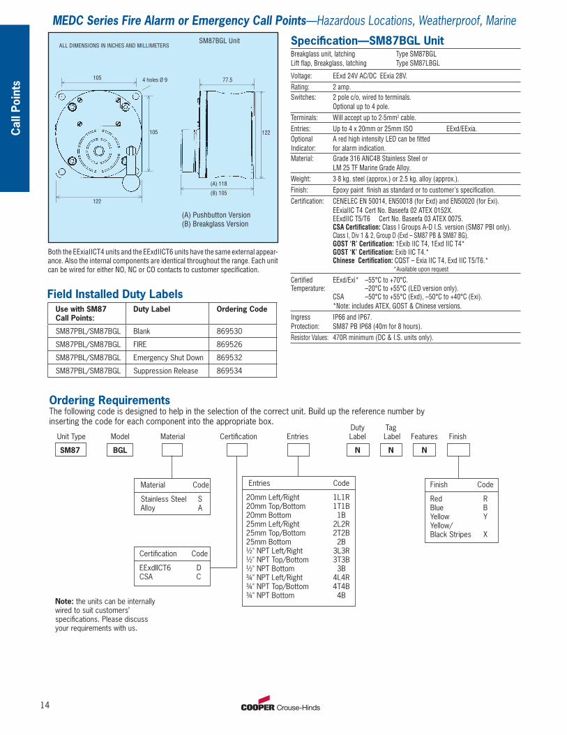
MEDC Series Fire Alarm or Emergency Call Points—Hazardous Locations, Weatherproof, Marine
Ordering RequirementsThe following code is designed to help in the selection of the correct unit. Build up the reference number by inserting the code for each component into the appropriate box.
Duty TagUnit Type Model Material Certifi cation Entries Label Label Features Finish
SM87 BGL N N N
Certifi cation Code
EExdIICT6 DCSA C
Note: the units can be internally wired to suit customers’ specifi cations. Please discuss your requirements with us.
Finish Code
Red RBlue BYellow YYellow/Black Stripes X
Material Code
Stainless Steel SAlloy A
Both the EExiaIICT4 units and the EExdIICT6 units have the same external appear-ance. Also the internal components are identical throughout the range. Each unit can be wired for either NO, NC or CO contacts to customer specifi cation.
ALL DIMENSIONS IN INCHES AND MILLIMETERS
105
105
122
(A) 118
(B) 105
(A) Pushbutton Version(B) Breakglass Version
122
77.54 holes Ø 9
Specifi cation—SM87BGL UnitBreakglass unit, latching Type SM87BGLLift fl ap, Breakglass, latching Type SM87LBGL
Voltage: EExd 24V AC/DC EExia 28V.Rating: 2 amp.Switches: 2 pole c/o, wired to terminals. Optional up to 4 pole.Terminals: Will accept up to 2·5mm2 cable.Entries: Up to 4 x 20mm or 25mm ISO EExd/EExia.Optional A red high intensity LED can be fi ttedIndicator: for alarm indication.Material: Grade 316 ANC4B Stainless Steel or LM 25 TF Marine Grade Alloy.Weight: 3·8 kg. steel (approx.) or 2.5 kg. alloy (approx.).Finish: Epoxy paint fi nish as standard or to customer's specifi cation.Certifi cation: CENELEC EN 50014, EN50018 (for Exd) and EN50020 (for Exi). EExiaIIC T4 Cert No. Baseefa 02 ATEX 0152X. EExdIIC T5/T6 Cert No. Baseefa 03 ATEX 0075. CSA Certifi cation: Class I Groups A-D I.S. version (SM87 PBI only). Class I, Div 1 & 2, Group D (Exd – SM87 PB & SM87 BG). GOST ‘R’ Certifi cation: 1Exib IIC T4, 1Exd IIC T4* GOST ‘K’ Certifi cation: Exib IIC T4.* Chinese Certifi cation: CQST – Exia IIC T4, Exd IIC T5/T6.*
*Available upon request
Certifi ed EExd/Exi* –55°C to +70°C.Temperature: –20°C to +55°C (LED version only). CSA –50°C to +55°C (Exd), –50°C to +40°C (Exi). *Note: includes ATEX, GOST & Chinese versions.Ingress IP66 and IP67.Protection: SM87 PB IP68 (40m for 8 hours).Resistor Values: 470R minimum (DC & I.S. units only).
Entries Code
20mm Left/Right 1L1R20mm Top/Bottom 1T1B20mm Bottom 1B25mm Left/Right 2L2R25mm Top/Bottom 2T2B25mm Bottom 2B½" NPT Left/Right 3L3R½" NPT Top/Bottom 3T3B½" NPT Bottom 3B¾" NPT Left/Right 4L4R¾" NPT Top/Bottom 4T4B¾" NPT Bottom 4B
Use with SM87 Call Points:
Duty Label Ordering Code
SM87PBL/SM87BGL Blank 869530
SM87PBL/SM87BGL FIRE 869526
SM87PBL/SM87BGL Emergency Shut Down 869532
SM87PBL/SM87BGL Suppression Release 869534
Field Installed Duty Labels
SM87BGL Unit
Cal
l Poi
nts

15
MEDC Series Fire Alarm or Emergency Call Points—Hazardous Locations, Weatherproof, Marine
Use with PB Call Points:
Duty Label Ordering Code
PB Blank 869530
PB FIRE 869526
PB Emergency Shut Down
869532
PB Suppression Release 869534
Field Installed Duty Labels
Ordering RequirementsThe following code is designed to help in the selection of the correct unit. Build up the reference number by inserting the code for each component into the appropriate box.
Entries Code
1 Bottom M20 5B2 Bottom M20 4B 6B1 Top, 1 Bottom M20 2B 5B1 Bottom 1/2" NPT 5C2 Bottom 1/2" NPT 4C 6C1 Top, 1 Bottom 1/2" NPT 2C 5C16 mm *A20 mm *B1/2" NPT *C* Prefi x entry size (see diagram above)
with entry position code e.g. 1A, 2A.
UL & CSA Versions only available with1/2" NPT entries
Finish Code
Red (Standard) RNatural Black NBlue BYellow YGray G
Certifi cation Code
ATEX/CENELEC – EExe EBATEX/CENELEC – EExi IBCSA – Exi (PBI only) ICUL – Class I, Div. 2 UL
For versions containing inline and end of line resistors, please spec i fy your re quire ments.
SW1 SW2
WIRING DIAGRAM DOUBLE SWITCH
TERMINALS
Basic single changeover switch wiring diagram
Basic double changeover switch wiring diagram
Specifi cation—PB UnitCertifi cation: UL Listed — Hazardous locations: Class I, Div. 2, Groups A, B, C, D and Class I, Zone 2. UL Listing No. E186629. Ordinary locations: Fire Alarm Boxes. UL Listing No. S8117. CSA Certifi ed to C22.2 (PB only), Nos. 0-M, 0.4M, 14-M, 25,30-M, 94, 142-M 1987, 157M 1987,
157–92, Enclosure Type 4, 4A, Class I, Groups A, B, C, D, Cert. No. 79120. ATEX Approved: EN50014, EN50018, EN50019, EN50028. Cert. No. BAS02ATEX2105X (BG & PB), EExed II C T6 (switch only), EExedm IIC T4 (other versions).Voltage: Up to 240V.Certifi ed Temperature: BGUL: -13°F to +131°F (-25°C to + 55°C); PBUL: -13°F to +131°F (-25°C to +55°C). PB (CSA): -58°F to +104°F (-50°C to +40°C).Ingress Protection: NEMA 4X & 6, IP66 & 67.Terminals: 7 x 14 AWG standard.Switch Rating (1 or 2changeover switches fi tted): Max Rating 240VAC, 3A.Cable Entries: Up to 4 entries ½" NPT or 20mm.Weight: 2.6 lb/1.2kg (Varies with model & entries).Material: Glass reinforced polyester.Finish: Red epoxy painted fi nish as standard or to Customer’s specifi cation.Resistors: Various confi gurations available on versions up to 24V, 470R minimum.LED Indication: A high intensity red LED can be fi tted as an optional extra to indicate operation on versions
up to 24V.Labeling: PB & BG Duty label — worded to Client’s requirements. Riveted on. PB & BG Tag label — worded to Client’s requirements. Screwed on.
SW1
WIRING DIAGRAM SINGLE SWITCH
TERMINALS
4 1/2"114mm
2 11/16"68mm
ALL DIMENSIONS IN INCHES AND MILLIMETERSDIMENSIONS FOR PUSHBUTTON AS BREAKGLASS (U.O.S.)FIXING HOLES 3/16" / 4.8mm DIA. (4 POSITIONS) IN EACH UNIT.
PB Unit
Model Certifi cation Entries Labels Switches Features Terminals Finish
PB N DS N 7
Call Points
Switches Code
DC double DDchange over
AC single ASchange over
AC double ADchange over

16
MEDC Series Fire Alarm or Emergency Call Points—Hazardous Locations, Weatherproof, Marine
Ordering RequirementsThe following code is designed to help in the selection of the correct unit. Build up the reference number by inserting the code for each component into the appropriate box.
Finish Code
Red (Standard) RNatural Black NBlue BYellow Y
Gray G
Certifi cation Code
ATEX/CENELEC – EExe EBATEX/CENELEC – EExi IBCSA – Exi (PBI only) ICUL – Class I, Div. 2 UL
For versions containing inline and end of line resistors, please spec i fy your re quire ments.
SW1 SW2
WIRING DIAGRAM DOUBLE SWITCH
TERMINALS
Basic single changeover switch wiring diagram
Basic double changeover switch wiring diagram
Specifi cation—BG UnitCertifi cation: UL Listed — Hazardous locations: Class I, Div. 2, Groups A, B, C, D and Class I, Zone 2. UL Listing No. E186629. Ordinary locations: Fire Alarm Boxes. UL Listing No. S8117. CSA Certifi ed to C22.2 (PB only), Nos. 0-M, 0.4M, 14-M, 25,30-M, 94, 142-M 1987, 157M 1987,
157–92, Enclosure Type 4, 4A, Class I, Groups A, B, C, D, Cert. No. 79120. ATEX Approved: EN50014, EN50018, EN50019, EN50028. Cert. No. BAS02ATEX2105X (BG & PB), EExed II C T6 (switch only), EExedm IIC T4 (other versions).Voltage: Up to 240V.Certifi ed Temperature: BGUL: -13°F to +131°F (-25°C to + 55°C); PBUL: -13°F to +131°F (-25°C to +55°C). PB (CSA): -58°F to +104°F (-50°C to +40°C).Ingress Protection: NEMA 4X & 6, IP66 & 67.Terminals: 7 x 14 AWG standard.Switch Rating (1 or 2changeover switches fi tted): Max Rating 240VAC, 3A.Cable Entries: Up to 4 entries ½" NPT or 20mm.Weight: 2.6 lb/1.2kg (Varies with model & entries).Material: Glass reinforced polyester.Finish: Red epoxy painted fi nish as standard or to Customer’s specifi cation.Resistors: Various confi gurations available on versions up to 24V, 470R minimum.LED Indication: A high intensity red LED can be fi tted as an optional extra to indicate operation on versions
up to 24V.Labelling: BG Glass label — reads either (1) Fire Break glass — press here. (2) Break glass — press here. (3) Worded to Client’s requirements. PB & BG Duty label — worded to Client’s requirements. Riveted on. PB & BG Tag label — worded to Client’s requirements. Screwed on.
SW1
WIRING DIAGRAM SINGLE SWITCH
TERMINALS
BG Unit
4 ¾"121mm
4 15
/16"
125m
m
2 15/16"75mm
2 13
/16"
71m
m
Model Certifi cation Entries Labels Switches Features Terminals Finish
BG DS N 7
Entries Code
1 Bottom M20 5B2 Bottom M20 4B 6B1 Top, 1 Bottom M20 2B 5B1 Bottom 1/2" NPT 5C2 Bottom 1/2" NPT 4C 6C1 Top, 1 Bottom 1/2" NPT 2C 5C16 mm *A20 mm *B1/2" NPT *C* Prefi x entry size (see diagram above)
with entry position code e.g. 1A, 2A.
UL & CSA Versions only available with1/2" NPT entries
Labels Code
Glass Label (1) 1“Fire Break Glass—Press Here”
Glass Label (2) 2“Break Glass—Press Here”
2 5/8" 75mm3 5/8" 92mm
5/8" 5/8" 16mm 16mm
Use with BG Call Points:
Duty Label Ordering Code
BG Blank 869531
BG FIRE 869525
BG Emergency Shut Down
869533
BG Suppression Release 869535
Field Installed Duty Labels
Cal
l Poi
nts
Switches Code
DC double DDchange over
AC single ASchange over
AC double ADchange over

17
MEDC Series Status Lights
Explosionproof, WeatherproofSM87 SL & XB12 SL Range
The most rugged and reliable status lights for harsh and hazardous applications.
Available as Xenon, incandescent and fl uorescent beacons/strobes.
The SM87 SL range is manufactured in marine grade alloy and the XB12 SL in corrosion-free GRP to provide a wide range of status lights to suit your requirements.
All units can be supplied as 1, 2, 3, 4 or 5 stacks.
Primary Applications■ Process status■ Messaging■ Alert or emergency condition indication
Industries■ Offshore & onshore■ Energy exploration & transmission■ Refi ning■ Chemical & petrochemical■ Pharmaceutical
Certifications & Compliances■ UL Listed for USA and Canada*
– Class I, Div. 1 & 2, Groups C & D
– Class I, Zone 1, AExd IIB T6■ CSA certifi ed*■ ATEX approved■ Xenon, fl uorescent, incandescent*■ NEMA 4X & 6, IP66 & 67■ Certifi ed temperature -67°F to +131°F*
-55°C to +55°C
Key Features & Benefi ts■ 4-wire monitored connection for
supervisory circuits*■ Marine grade alloy or GRP■ Pre-wired to customer’s requirements
*Depending on model
SM87 SL
XB12 SL
Note: Units shown are for representation only. Other variations are available.
Status Lights

18
MEDC Series Status Lights—Explosionproof, Weatherproof
Xenon, Incandescent & Fluorescent Status Lights—ExplosionproofSM87 SLCertifi cation ATEXUL Listed for: Class I, Div 1, Groups C & D,
Class I, Zone 1, AExd IIB T4
Certifi ed Ambient Temperature -67 °F to +158 °F -55°C to +70°C
Ingress Protection NEMA 4X & 6 IP66 & 67
Material Alloy
Entries Up to 1 x ½" NPT
Max. No. of Ways 4
Options: Body & lens color, certifi cation, voltages 24–48V DC, 110–254V AC
Certifi cation Voltage Ordering Code Catalog # Standard Product Confi guration
UL, cUL Listed, Class I, Div 1, Groups C & D
24V DC 26200043 SM87SL3 Explosion protected, three stack, one ½" NPT entry on bottom, no lens guards, xenon strobe with red, green, and clear lens
UL, cUL Listed, Class I, Div 1, Groups C & D
24V DC 26200055 SM87SL2 Xenon status lamp, two stack 5 joule beacons interconnected on a painted red stainless steel baseplate, one red and one green lens color, ½" NPT entry in the bottom unit for customer connection
UL, cUL Listed, Class I, Div 1, Groups C & D
24V DC 26200056 SM87SL2 Incandescent status lamp, two stack 40 watt beacons interconnected on a painted red stainless steel baseplate, one red and one green lens color, ½" NPT entry in the bottom unit for customer connection
UL, cUL Listed, Class I, Div 1, Groups C & D
24V DC 26200057 SM87SL2 Fluorescent status lamp, two stack 5 watt beacons interconnected on a painted red stainless steel baseplate, one red and one green lens color, ½" NPT entry in the bottom unit for customer connection
UL, cUL Listed, Class I, Div 1, Groups C & D
110V AC 26200058 SM87SL2 Xenon status lamp, two stack 5 joule beacons interconnected on a painted red stainless steel baseplate, one red and one green lens color, ½" NPT entry in the bottom unit for customer connection
UL, cUL Listed, Class I, Div 1, Groups C & D
24V DC 26200059 SM87SL3 Xenon status lamp, three stack 5 joule beacons interconnected on a painted red stainless steel baseplate, one red, one amber and one green lens color, ½" NPT entry in the bottom unit for customer connection
UL, cUL Listed, Class I, Div 1, Groups C & D
24VDC 26200060 SM87SL3 Incandescent status lamp, three stack 40 watt beacons interconnected on a painted red stainless steel baseplate, one red, one amber and one green lens color, ½" NPT entry in the bottom unit for customer connection
UL, cUL Listed, Class I, Div 1, Groups C & D
24V DC 26200061 SM87SL3 Fluorescent status lamp, three stack 5 watt beacons interconnected on a painted red stainless steel baseplate, one red, one amber and one green lens color, ½" NPT entry in the bottom unit for customer connection
UL, cUL Listed, Class I, Div 1, Groups C & D
110V AC 26200062 SM87SL3 Xenon status lamp, three stack 5 joule beacons interconnected on a painted red stainless steel baseplate, one red, one amber and one green lens color, ½" NPT entry in the bottom unit for customer connection
UL, cUL Listed, Class I, Div 1, Groups C & D
110V AC 26200066 SM87SL3 Incandescent status lamp, three stack 40 watt beacons interconnected on a painted red stainless steel baseplate, one red, one amber and one green lens color, ½" NPT entry in the bottom unit for customer connection
UL, cUL Listed, Class I, Div 1, Groups C & D
220V AC 26200063 SM87SL3 Fluorescent status lamp, three stack 5 watt beacons interconnected on a painted red stainless steel baseplate, one red, one amber and one green lens color, ½" NPT entry in the bottom unit for customer connection
Stat
us L
ight
s

19
Xenon Strobe & Incandescent Status Lights—Hazardous LocationsXB11 SLULCertifi cation ATEXUL Listed for: Class I, Div 2, Groups C & D,
Class I, Zones 1 & 2, AExd IIB T4
Certifi ed Ambient Temperature -67°F to +158°F -55°C to +70°C
Ingress Protection NEMA 4X & 6 IP66 & 67
Material Corrosion-free GRP
Entries 1 x ½" NPT
Max. No. of Ways 5
Options: Body & lens color, tag & duty labels
Xenon Strobe & Incandescent Status Lights—Hazardous LocationsXB12 SL/FB12 SLCertifi cation ATEX UL Listed for: Class I, Div 2, Groups C & D, Class I, Zones 1 & 2, AExd IIB T4
Certifi ed Ambient Temperature -67°F to+158°F -55°C to +70°C
Ingress Protection NEMA 4X & 6 IP66 & 67
Material Corrosion-free GRP
Entries 1 x ½" NPT
Max. No. of Ways 5
Options: Body & lens color, certifi cation, voltages 24V DC, 110–254V AC
Certifi cation Ordering Code Catalog # Standard Product Confi guration
UL Listed, Class I, Div 2, Groups C & D 42500005 XB11ULSL3 Explosion protected, 3 stack, one ½" NPT entry on bottom, 24V DC, green incandescent on top, yellow xenon fl ashing in middle, red xenon fl ashing on bottom, no lens guards, red fi nish
Certifi cation Ordering Code Catalog # Standard Product Confi guration
UL Listed, Class I, Div 2, Groups C & D 42600001 XB12ULSL3 110V AC, explosion protected, three stack, one ½" NPT entries, red xenon fl ashing on top, amber xenon fl ashing in middle, clear xenon fl ashing on bottom; no lens guards, red fi nish
UL Listed, Class I, Div 2, Groups C & D 42600007 XB12ULSL2 24V DC xenon status lamp, two stack 21 joule beacons interconnected on a painted red stainless steel baseplate, one red and one green lens color, ½" NPT entry in the bottom unit for customer connection
UL Listed, Class I, Div 2, Groups C & D 42600008 FB12ULSL2 24V DC incandescent status lamp, two stack 60W beacons interconnected on a painted red stainless steel baseplate, one red and one green lens color, ½" NPT entry in the bottom unit for customer connection
UL Listed, Class I, Div 2, Groups C & D 42600009 XB12ULSL3 24V DC xenon status lamp, three stack 21 joule beacons interconnected on a painted red stainless steel baseplate, one red, one amber and one green lens color, ½" NPT entry in the bottom unit for customer connection
UL Listed, Class I, Div 2, Groups C & D 42600010 FB12ULSL3 24V DC incandescent status lamp, three stack 60W beacons interconnected on a painted red stainless steel baseplate, one red, one amber and one green lens color, ½" NPT entry in the bottom unit for customer connection
MEDC Series Status Lights—Explosionproof, WeatherproofStatus Lights

20
MEDC Series Status Lights—Explosionproof, Weatherproof
SM87 SLTypical four unit assembly. Various options are available.
8 5/8" 219mm
8 5/8" 219mm
19 11/16" 500mm
67/8" 175mm
5 7/8" 149mm
6 11/16" 170mm
6 FIXING HOLES Ø 7/16" / 11mm
ALL MEASUREMENTS IN INCHES AND MILLIMETERS
XB12 SLTypical two unit assembly. Various options are available.
Specifi cation—SM87SL Unit and XB12SL Unit SM87 SL XB12 SL Lamp Types Xenon 5 joules maximum. Xenon 21 joules. Fluorescent 10W or 5W. Incandescent 40W maximum. Incandescent 60W.
Voltage Frequency 50 Hz as standard. 60 Hz available if required.
Xenon Voltages 24, 48V DC 110, 120, 240, 254V AC 24V DC, 110V, 240V AC (see SM87 HXB data sheet for further information) (see XB12 data sheet for further information)
Incandescent Voltages 12, 24, 48V DC, 110, 220, 240, 254V AC 120V AC (see SM87 LU3 data sheet for further information) (see FB12 data sheet for further information)
Fluorescent Voltages 12, 24, 48V, 220, 240, 254V AC – (see SM87 LU1 data sheet for further information)
Lamp Colors Red, Amber, Yellow, Green, Blue or Clear.
Certifi cation UL Listed for USA and Canada Class I, Div 1, Groups UL Listed for USA and Canada Class I, Div 2, C & D, Class I, Zone 1, AExd IIB T6. Listing No. E187894. Groups C & D, Class I, Zones 1 & 2, AExd IIB T4/T5. CSA Certifi ed: Class I, Div 1 & 2, Group D. Cert. No. 96406. Listing No. E187894. ATEX Approved: ATEX Approved: EExd IIB T4/T5. EExd IIC T4 (incandesent), EExd IIC T6 (Fluorescent & Xenon). Cert. No. 99 ATEX 2196 Cert. No. Baseefa 03ATEX0222X, CENELEC EN50014 and EN50018. CENELEC EN50014, EN50018.
Terminals Will accept up to 14AWG cable. Will accept up to 6 off 10AWG cable.
Wiring Standard confi guration of internal wiring is to common the negative/neutral connections. If individually wired lamps are required, please state requirements.
Entries Up to 3 x ½" or ¾" NPT. 1 x ½" NPT.
Enclosure LM 25TF Marine Grade Alloy. GRP.
Lens Glass
Finish Epoxy paint as standard or to customer’s specifi cation. Natural Black or Epoxy paint to customer’s specifi cation.
Ingress Protection NEMA 4X and 6, IP66 & 67.
Ambient Temp. -13°F to 131°F (-25°C to +55°C) – Class I, Div 1. -67°F to +158°F (-55°C to +70°C). -67°F to +131°F (-55°C to +55°C) – Class I, Zone 1.
ALL MEASUREMENTS IN INCHES AND MILLIMETERS
Note: XB11 SLUL also available.
XB11 SL
SM87 SL(typical three unit assembly)
Stat
us L
ight
s

21
Cooper Crouse-Hinds and MEDC provides a complete line of Strobe Lights and rotating beacons for harsh and hazardous visual indications.
■ Products that meet world-wide standards such as UL, cUL, CSA, ATEX and GOST, and all Class, Division & Zone area classifi cations
■ Products designed for both conduit wiring and/or cable connection, NPT or metric
■ Complete line of strobe light output intensities, strobe light colors and operating voltages
■ Units designed for use in fi re alarm circuits meeting National Fire Protection Agency requirements for visual signaling for the hearing impaired
What Types of Signals are Available?1. Strobe Lights — Used for signaling or warning of
various conditions. Emits a powerful blast of bright light.
2. Rotating Beacons — Used to signal over a large area when the light must be seen from a long distance.
3. Steady-on Beacons — Typically used as a continuous source to warn, commumicate or draw attention to an area, machine or process.
4. Stack Lights — Used for multiple indication in one signaling device. Compact and versatile, the three-color (red, amber and green) is most popular.
Lens Color and Their ApplicationsMost Cooper Crouse-Hinds strobes, steady and fl ashing beacons come in six lens coors: amber, blue, clear, green, magenta and red. Cooper Crouse-Hinds LED signals come in amber, blue, green, red and, in some cases, white. The following are examples of how various lens colors are used in industrial and commercial signaling environments:
Amber — Denotes caution.
Blue — Used for safety and security.
Clear (or White) & Green — Used to indicate normal run operation.
Clear for Fire Alarm Applications — Used to indicate a fi re emergency.
Magenta — Used for radiaton alarms.
Red — Denotes emergency or warning.
Strobes, Rotating Beacons and Indicating Lights Hazardous Locations, Weatherproof
Hazard•Gard™ Series
MEDC® Series
EXS301 Strobe Light
EXS0301 Steady-on
Indicating Light
EXR301 Rotating Beacon
XB12
XB16
XB11
XB15
Strobes, Rotating Beacons & Indicating Lights

22
MEDC SeriesStrobe Warning Light
Hazardous Locations, Weatherproof
XB15 Pipe Mount (with cast guard)
XB15Direct Mount(with wire guard)
XB16
These listed strobes have been designed for use in potentially explosive atmospheres and harsh environmental conditions. The enclosures are suitable for use offshore or onshore, where a lightweight product combined with corrosion resistance is required.
The housing is manufactured from a U.V. stable, glass reinforced polyester, with the lens manufactured from a U.V. stable polycarbonate. Stainless steel screws are used ensuring a totally corrosion-free product.
The strobes contain supervisory diode and four wire leads for fi re alarm applications. This strobe is also available UL 1971 (ADA) Listed for hearing impaired applications.
Units can be painted to customer specifi cation and supplied with identifi cation labels.
Primary Applications■ Condition signaling■ Security alert■ Equipment obstruction warning■ Emergency evacuation signaling
Typical Industries■ Utility gas plants■ Wastewater treatment plants■ Mining■ Petroleum refi neries■ Chemical & petrochemical■ Pulp & paper
Certifi cations & Compliances■ UL Listed for USA and Canada
– Hazardous locations for USA and Canada
Class I, Div. 2, Groups A, B, C & D*
UL 1971 compliant version available†
– Ordinary locations: Visual Signal Device■ NEMA 4X and 6, IP66 & 67■ Certifi ed temperature -67°F to +158°F
-55°C to +70°C
Key Features & Benefits■ Pipe mount with ½" NPT entry■ Corrosion resistant GRP enclosure■ XB16 580,000 peak candlepower
XB15 520,000 peak candlepower■ Polycarbonate lens, various colors available†
■ 4 wire diode monitored board■ Optional relay initiate■ Optional lens guard
*Conforms to UL regulated voltage †UL 1971 version available with clear lens only (XB16 only)
UL 1971 Compliant
New!St
robe
s, Ro
tatin
g Be
acon
s & In
dica
ting
Ligh
ts

23
MEDC Series Strobe Warning Light—Hazardous Locations, Weatherproof
15 Joule Flashing Xenon—Hazardous & Ordinary LocationsXB15Certifi cation ATEXUL Listed for: Class I, Div 2, Groups A,B,C,D Class I, Zones 1 & 2, AExd IIC T5/T6
Certifi ed Ambient Temperature -67°F to +158°F -55°C to +70°C
Ingress Protection NEMA 4X & 6 IP66 & 67
Material Corrosion-free GRP
Entries Up to 3 x ½" NPT or 3 x ¾" NPT
Weight 6–8lb/2.6-3.6kg
Options: Body & lens color, voltages 12–48V DC, 110–254V ACDirect Mount Pipe Mount
Certifi cation Voltage Lens Color Ordering Code Catalog # Standard Product Confi guration
UL, cUL Listed, Class I, Div 2, Groups A, B, C, D 120V AC Red 869400 XB15UL12006RWBNN 15 joules, direct mount w/backstrap, 2 x ¾" NPT side entries, wire guard, 60 fl ashes per minute, natural black fi nishUL, cUL Listed, Class I, Div 2, Groups A, B, C, D 120V AC Amber 869401 XB15UL12006AWBNN
UL, cUL Listed, Class I, Div 2, Groups A, B, C, D 120V AC Red 869402 XB15UL12006RWPNN 15 joules, pipe mount, 1 x ¾" NPT entry, wire guard, 60 fl ashes per minute, natural black fi nishUL, cUL Listed, Class I, Div 2, Groups A, B, C, D 120V AC Amber 869403 XB15UL12006AWPNN
UL, cUL Listed, Class I, Div 2, Groups A, B, C, D 24V DC Clear 27600042 XB15UL02406CWBNN
15 joule beacon, 60 fl ashes per minute, wire guard, backstrap, 2 x ¾" NPT entries, natural black enclosure
UL, cUL Listed, Class I, Div 2, Groups A, B, C, D 24V DC Green 27600043 XB15UL02406GWBNN
UL, cUL Listed, Class I, Div 2, Groups A, B, C, D 24V DC Blue 869393 XB15UL02406BWBNN
UL, cUL Listed, Class I, Div 2, Groups A, B, C, D 24V DC Red 869398 XB15UL02406RWBNN
UL, cUL Listed, Class I, Div 2, Groups A, B, C, D 24V DC Amber 869399 XB15UL02406AWBNN
UL, cUL Listed, Class I, Div 2, Groups A, B, C, D 24V DC Clear 27600047 XB15UL02406CWPNN
15 joule beacon, 60 fl ashes per minute, wire guard, pipe mounting, 1 x ¾" NPT entry, natural black enclosure
UL, cUL Listed, Class I, Div 2, Groups A, B, C, D 24V DC Green 27600048 XB15UL02406GWPNN
UL, cUL Listed, Class I, Div 2, Groups A, B, C, D 24V DC Blue 869394 XB15UL02406BWPNN
UL, cUL Listed, Class I, Div 2, Groups A, B, C, D 24V DC Red 869396 XB15UL02406RWPNN
UL, cUL Listed, Class I, Div 2, Groups A, B, C, D 24V DC Amber 869397 XB15UL02406AWPNN
UL, cUL Listed, Class I, Div 2, Groups A, B, C, D 120V AC Clear 27600052 XB15UL12006CWBNN
15 joule beacon, 60 fl ashes per minute, wire guard, backstrap, 2 x ¾" NPT entries, natural black enclosure
UL, cUL Listed, Class I, Div 2, Groups A, B, C, D 120V AC Green 27600053 XB15UL12006GWBNN
UL, cUL Listed, Class I, Div 2, Groups A, B, C, D 120V AC Blue 869405 XB15UL12006BWBNN
UL, cUL Listed, Class I, Div 2, Groups A, B, C, D 120V AC Clear 27600057 XB15UL12006CWPNN
15 joule beacon, 60 fl ashes per minute, wire guard, pipe mounting, 1 x ¾" NPT entry, natural black enclosure
UL, cUL Listed, Class I, Div 2, Groups A, B, C, D 120V AC Green 27600058 XB15UL12006GWPNN
UL, cUL Listed, Class I, Div 2, Groups A, B, C, D 120V AC Blue 869404 XB15UL12006BWPNN
New!
Strobes, Rotating Beacons & Indicating Lights

24
MEDC Series Strobe Warning Light—Hazardous Locations, Weatherproof
10 Joule Flashing Xenon—Hazardous & Ordinary LocationsXB16 ULCertifi cation UL 1971 compliantUL Listed for: Class I, Div 2, Groups A, B, C, D
Certifi ed Ambient Temperature -67°F to +158°F -55°C to +70°C
Ingress Protection NEMA 4X & 6 IP66 & 67
Material Corrosion-free GRP
Entries Standard 1 x ½" NPT
Weight 2.2lb/1kg
Options: Body & lens color, lens guard, voltages 12–48V DC,110–254V AC
Certifi cation Voltage Lens Color Ordering Code Catalog # Standard Product Confi guration
UL 1971 compliant 24V DC Clear 29600023 XB16US02460CYNN
UL 1971 Listed for Signaling devices for the hearing impaired. Suitable for fi re alarm indication. 10 joule beacon, 60 fl ashes per minute, lens guard, pipe mounting, 1 x ½" NPT entry, natural black enclosure
UL, cUL Listed, Class I, Div 2, Groups A, B, C, D
120V AC Blue 869406 XB16UL12060BYNN
10 joules, 60 fl ashes per minute, 1 x ½" NPT entry, 240 Cd, lens guard, natural black fi nish
UL, cUL Listed, Class I, Div 2, Groups A, B, C, D
120V AC Red 869407 XB16UL12060RYNN
UL, cUL Listed, Class I, Div 2, Groups A, B, C, D
120V AC Amber 869408 XB16UL12060AYNN
UL, cUL Listed, Class I, Div 2, Groups A, B, C, D
120V AC Clear 29600013 XB16UL12060CYNN
10 joule beacon, 60 fl ashes per minute, lens guard, pipe mounting, 1 x ½" NPT entry, natural black enclosure
UL, cUL Listed, Class I, Div 2, Groups A, B, C, D
120V AC Green 29600014 XB16UL12060GYNN
UL, cUL Listed, Class I, Div 2, Groups A, B, C, D
120V AC Blue 29600011 XB16UL12060BYNN
UL, cUL Listed, Class I, Div 2, Groups A, B, C, D
120V AC Red 29600003 XB16UL12060RYNN
UL, cUL Listed, Class I, Div 2, Groups A, B, C, D
120V AC Amber 29600004 XB16UL12060AYNN
UL, cUL Listed, Class I, Div 2, Groups A, B, C, D
24V DC Green 29600016 XB16UL02460GYNN
10 joule beacon, 60 fl ashes per minute, lens guard, pipe mounting, 1 x ½" NPT entry, natural black enclosure
UL, cUL Listed, Class I, Div 2, Groups A, B, C, D
24V DC Blue 29600017 XB16UL02460BYNN
UL, cUL Listed, Class I, Div 2, Groups A, B, C, D
24V DC Red 869410 XB16UL02460RYNN
UL, cUL Listed, Class I, Div 2, Groups A, B, C, D
24V DC Amber 869411 XB16UL02460AYNN
New!
Stro
bes,
Rota
ting
Beac
ons &
Indi
catin
g Li
ghts

25
Color Code
Red R Blue B Green G Amber A Yellow Y Clear C
Voltage Code
24V DC 024 110V AC 110 120V AC 120 240V AC 240
Guard Code
None N Cast C Wire W
Ordering RequirementsThe following code is designed to help in the selection of the correct unit. Build up the reference number by inserting the code for each component into the appropriate box.
Unit Fixing Code
Pipe mount P* Direct w/backstrap B
Certifi cation Code
ATEX B UL UL
*Not available on ATEX version.
Specifi cation—XB15 UnitCertifi cation: UL Listed for USA and Canada: – Hazardous locations Class I, Div 2, groups A, B, C & D Class I, Zone 1, AExd IIC T5/T6 UL listing No. E187894. – Ordinary locations: Visual Signal Device UL listing No. S8128 CENELEC/ATEX approved. CENELEC EN50014 & EN50018 ATEX Cert. No. Baseefa 04ATEX0009X.Material: Body: Glass reinforced polyester. Lens: Glass. Backstrap: stainless steel 316. Wire Guard (optional): Stainless steel wire. Cast Guard (optional): Aluminium LM25M.Finish: Natural black or epoxy painted to customer specifi cation.Voltage: 24, 48V DC 110, 120, 230, 240, 254V ACTube Energy: 15 joules.Tube Life: >1 x 10⁶ fl ashes.Flash Rate: 60, 80, 120 fpm.Certifi ed -67°F to +131°F (-55°C to +55°C) T6.Temperature: -67°F to +158°F (-55°C to +70°C) T5.Weight: Pipe mount: 5¾lb/2.6kg; Direct mount: 6½lb/3.0kg.Ingress NEMA 4X & 6, IP66 & IP67.Protection:Entries: Supplied as 2 x ¾" NPT (direct mount) or ¾" (pipe mount) as
standard. Other options available: Up to 3 x ½" NPT or 3 x ¾" NPT (direct mount); ½" NPT (pipe mount) — contact sales offi ce to order.Terminals: Direct mount: 12 x 14AWG. Pipe mount: 8 x 14AWG.Relay Initiate: Available on all units — suitable for 24V DC supplies only.Labels: Tag/Duty label option.
Electrical Ratings: DC ACVoltage 24 48 110 120 230 240 254Current (A) at 60 fpm .78 .67 0.4 0.4 0.2 0.2 0.17Current (A) at 80 fpm .99 .73 0.4 0.4 0.2 0.2 0.17Current (A) at 120 fpm .99 .73 0.4 0.4 0.2 0.2 0.17
Effective Candlepower 330 (Effective candlepower is the intensity that would appear to an observer if the light was burning steadily)
Peak Candlepower 520,000 (Peak candlepower is the maximum light intensity generated by a fl ashing light during its light pulse)
Multiplying Factor for Colored Lenses:
Red Blue Amber Green Yellow
0.15 0.12 0.51 0.49 0.86
XB15 Unit
Lens Lens Unit Unit Model Certifi cation Voltage Flashrate Color Guard Fixing Options Finish
XB15 06 N N
MEDC Series Strobe Warning Light—Hazardous Locations, Weatherproof
Lens Flashrate Code
08 80 fpm 12 120 fpm
Strobes, Rotating Beacons & Indicating Lights

26
MEDC Series Strobe Warning Light—Hazardous Locations, Weatherproof
Lens Flashrate Code
80 80 fpm 120 120 fpm
XB16 RANGE(Shown with optional guard fi tted)
All dimensions in inches and millimeters
Electrical Ratings:For Hazardous Locations and Ordinary Locations (UL1638) Units
DC ACVoltage 24 48 110 120 230 240 254Current (A) at 60 fpm 0.89 0.30 0.38 0.38 0.22 0.22 0.18Current (A) at 80 fpm 0.89 0.30 0.38 0.38 0.22 0.22 0.18Current (A) at 120 fpm 0.89 0.30 0.38 0.38 0.22 0.22 0.18
Effective intensity (Cd): 240 at 80 f.p.m.Peak candlepower: 580,000 (Peak candlepower is the maximum light intensity
generated by a fl ashing light during its light pulse)
For UL1971 Units Only DC ACVoltage 24 48 110 120 230 240 254Current (A) at 60 fpm 1.22 1.52 0.38 0.38 0.78 0.78 0.18Current (A) at 80 fpm 1.22 1.52 0.38 0.38 0.78 0.78 0.18Current (A) at 120 fpm 1.22 1.52 0.38 0.38 0.78 0.78 0.18
Effective intensity (Cd): 240 at 80 f.p.m.Peak candlepower: 580,000 (Peak candlepower is the maximum light intensity
generated by a fl ashing light during its light pulse)Note: on UL1971 units, max. current rating is based on in-rush current. This iswhy the current ratings are not propotional as with other beacons/strobes.
UL 1971 On-axis output: 15 Cd.
Note: 24V DC units are cerifi ed for use in regulated 24V DC supplies (16–33V AC)110/120V DC units are certifi ed for use on regulated 120V AC supplies (96–132V AC) 230/240V DC units are certifi ed for use on regulated 240V AC supplies (192–264V AC)
Multiplying factor for colored lenses: Red Blue Amber Green Yellow 0.15 0.12 0.51 0.49 0.86
Relay Initiate: 24V DC relay initiate only.Relay Initiate: 24V DC relay initiate only.
Specifi cation—XB16UL UnitCertifi cation: UL Listed for USA and Canada: – Hazardous locations for USA and Canada Class I, Div 2, groups A, B, C & D. UL listing No. E251185. – Ordinary locations: Visual Signal Device: UL1638. UL listing No. E251185. – Hazardous locations for hearing impaired: UL1971. UL listing No. E251185.
Material: Body: Glass reinforced polyester. Lens: U.V. stable polycarbonate. Lens screws: stainless steel 316.
Finish: Natural black or painted to customer specifi cation.
Voltage: 24, 48V DC 110, 120, 230, 240, 254V AC Conforms to UL regulated voltage output (12V DC, 24V DC,
120V AC, 240V AC).
Certifi ed -67°F to +158°F (-55°C to +70°C)Temperature:
Tube Energy: 10 joules.
Tube life: >1 x 10⁶ fl ashes.
Weight: 2.2lb/1.0kg.Ingress NEMA 4X & 6, IP66 & IP67.Protection:Entries: Standard 1 x ½" NPT pipe mount.Terminals: 8 x 14AWG.Labels: Tag/Duty label option.
Color Code
Red R Blue B Green G Amber A Yellow Y Clear C
Voltage Code
12V DC 012 24V DC 024 110V AC 110 120V AC 120 240V AC 240
Guard Code
Yes Y None N
Ordering RequirementsThe following code is designed to help in the selection of the correct unit. Build up the reference number by inserting the code for each component into the appropriate box.
Model Certifi cation Voltage Flashrate Lens Color Guard Options Unit Finish
XB16 UL 60 N N
Certifi cation Code
UL UL
Stro
bes,
Rota
ting
Beac
ons &
Indi
catin
g Li
ghts

27
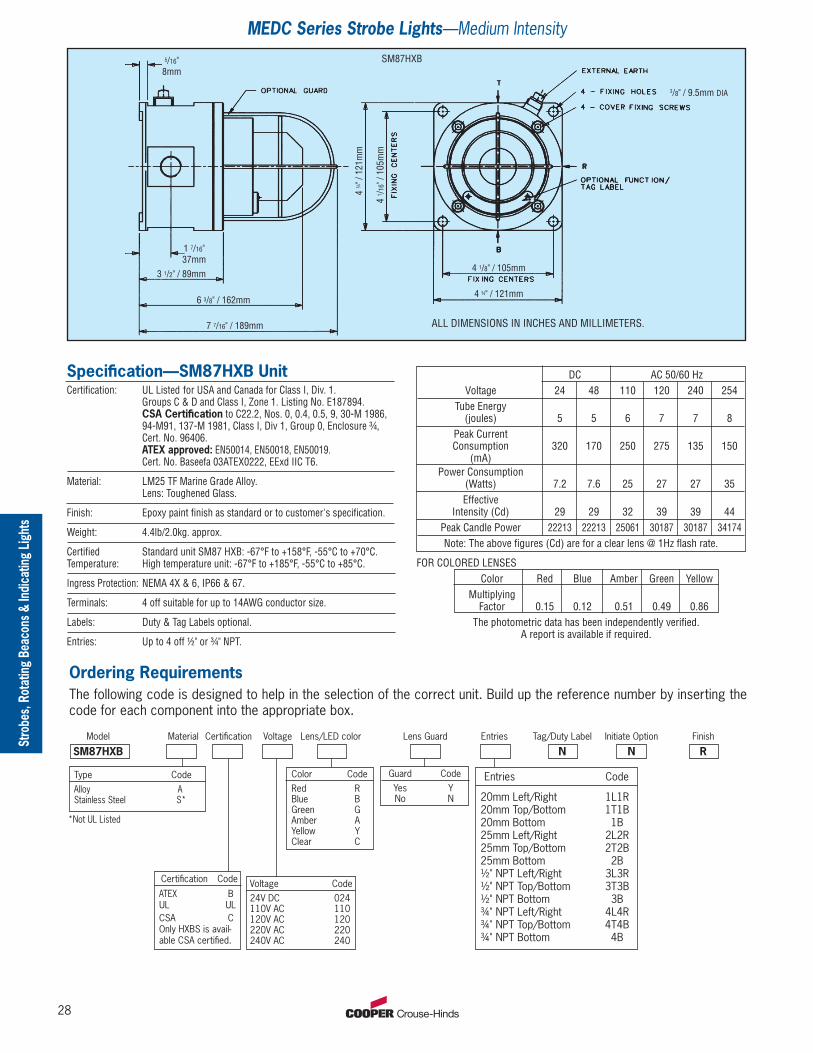
MEDC Series Strobe Lights—Medium Intensity
5 Joule Xenon Strobe—ExplosionproofSM87 HXBCertifi cation ATEXUL Listed for: Class I, Div 1, Groups C & D, Class I, Zone 1
Certifi ed Ambient Temperature -67°F to +158°F -55°C to +70°C
Ingress Protection NEMA 4X & 6 IP66 & 67
Material Alloy
Entries Up to 2 x ½" or ¾" NPT, M20, M25
Weight 4.4lb/2.0kg approx
Options: Body & lens color, certifi cation, lens guard, voltages 24–48V DC,110–254V AC
5 Joule Xenon Strobe—Hazardous LocationsXB11Certifi cation ATEXUL Listed for: Class I, Div 2, Groups C & D, Class I, Zones 1 & 2, AExd IIB T5
Certifi ed Ambient Temperature -67°F to +158°F -55°C to +70°C
Ingress Protection NEMA 4X & 6 IP66 & 67
Material Corrosion-free GRP
Entries 2 x ½" NPT, 20mm
Weight 2.6lb/1.2kg
Options: Body & lens color, voltages 24V DC, 110–254V AC
Certifi cation Voltage Lens Color Ordering Code Catalog # Standard Product Confi guration
ATEX EX II 2GD 24V DC Red 813005 SM87HXBAB024RN1R1LNNR 5 joules, 2 x M20 Entries, 29Cd, EExd IIcATEX EX II 2GD 24V DC Amber 813006 SM87HXBAB024AN1R1LNNR
ATEX EX II 2GD 240V AC Red 813007 SM87HXBAB240RN1R1LNNR 7 joules, 2 x M20 Entries, 39Cd, EExd IIcATEX EX II 2GD 240V AC Amber 813008 SM87HXBAB240AN1R1LNNR
ATEX EX II 2GD 24V DC Red LED 813009 SM87LEDAB024RN1R1LNNR 192Cd, 2 x M20 Entries, EExd IIc
UL, cUL Listed, Class I, Div 1,
Groups C & D24V DC Red 869161 SM87HXBAUL024RN3R3LNNR Standard models are in alloy, red
body color, no tag or duty labels, 2 x ½" NPT entries, 29Cd, 60 fl ashes per minute
UL, cUL Listed, Class I, Div 1,
Groups C & D24V DC Amber 869162 SM87HXBAUL024AN3R3LNNR
UL, cUL Listed, Class I, Div 1,
Groups C & D110V AC Red 869165 SM87HXBAUL110RN3R3LNNR Standard models are in alloy, red
body color, no tag or duty labels, 2 x ½" NPT entries, 32Cd, AExd IIB, 60 fl ashes per minute
UL, cUL Listed, Class I, Div 1,
Groups C & D110V AC Amber 869166 SM87HXBAUL110AN3R3LNNR
Certifi cation Voltage Body Color Lens Ordering Code Catalog # Standard Confi guration
UL, cUL Listed, Class I, Div 2, Groups C & D 24V DC Red Red 869171 XB11UL02406RNBNNNR
No tag or duty labels, 2 x ½" NPT entries, 60 fl ashes per minute
UL, cUL Listed, Class I, Div 2, Groups C & D 24V DC Red Amber 869172 XB11UL02406ANBNNNR
UL, cUL Listed, Class I, Div 2, Groups C & D 24V DC Natural Black Clear 869173 XB11UL02406CNBNNNN
UL, cUL Listed, Class I, Div 2, Groups C & D 24V DC Red Clear 869174 XB11UL02406CNBNNNR
UL, cUL Listed, Class I, Div 2, Groups C & D 110V AC Red Red 869175 XB11UL11006RNBNNNR
ATEX EX II 2GD 24V DC Natural Black Red 811101 XB11B02406RNBNNNN GRP, natural black body, no tag or duty labels, backstrap mounting, 2 x M20 entries, 60 fl ashes per minute
ATEX EX II 2GD 24V DC Natural Black Amber 811102 XB11B02406ANBNNNN
ATEX EX II 2GD 24V DC Natural Black Red 811103 XB11B24006RNBNNNN
ATEX EX II 2GD 24V DC Natural Black Amber 811104 XB11B24006ANBNNNN
Strobes, Rotating Beacons & Indicating Lights
28
MEDC Series Strobe Lights—Medium Intensity
Specifi cation—SM87HXB UnitCertifi cation: UL Listed for USA and Canada for Class I, Div. 1. Groups C & D and Class I, Zone 1. Listing No. E187894. CSA Certifi cation to C22.2, Nos. 0, 0.4, 0.5, 9, 30-M 1986,
94-M91, 137-M 1981, Class I, Div 1, Group 0, Enclosure ¾, Cert. No. 96406.
ATEX approved: EN50014, EN50018, EN50019. Cert. No. Baseefa 03ATEX0222, EExd IIC T6.
Material: LM25 TF Marine Grade Alloy. Lens: Toughened Glass.
Finish: Epoxy paint fi nish as standard or to customer's specifi cation.
Weight: 4.4lb/2.0kg. approx.
Certifi ed Standard unit SM87 HXB: -67°F to +158°F, -55°C to +70°C.Temperature: High temperature unit: -67°F to +185°F, -55°C to +85°C.
Ingress Protection: NEMA 4X & 6, IP66 & 67.
Terminals: 4 off suitable for up to 14AWG conductor size.
Labels: Duty & Tag Labels optional.
Entries: Up to 4 off ½" or ¾" NPT.
DC AC 50/60 Hz Voltage 24 48 110 120 240 254 Tube Energy (joules) 5 5 6 7 7 8 Peak Current Consumption 320 170 250 275 135 150 (mA) Power Consumption (Watts) 7.2 7.6 25 27 27 35 Effective Intensity (Cd) 29 29 32 39 39 44 Peak Candle Power 22213 22213 25061 30187 30187 34174
Note: The above fi gures (Cd) are for a clear lens @ 1Hz fl ash rate.
FOR COLORED LENSES Color Red Blue Amber Green Yellow Multiplying Factor 0.15 0.12 0.51 0.49 0.86
The photometric data has been independently verifi ed.A report is available if required.
5/16"8mm
1 7/16"37mm
6 3/8" / 162mm
3 1/2" / 89mm
7 7/16" / 189mm
4 ¾" /
121
mm
4 1 /1
6" / 1
05m
m
4 1/8" / 105mm
4 ¾" / 121mm
3/8" / 9.5mm DIA
ALL DIMENSIONS IN INCHES AND MILLIMETERS.
Ordering RequirementsThe following code is designed to help in the se lec tion of the correct unit. Build up the reference number by inserting the code for each component into the appropriate box.
Type Code
Alloy A Stainless Steel S*
Color Code
Red R Blue B Green G Amber A Yellow Y Clear C
Voltage Code
24V DC 024 110V AC 110 120V AC 120 220V AC 220 240V AC 240
Certifi cation Code
ATEX BUL UL
CSA COnly HXBS is avail-able CSA certifi ed.
SM87HXB
Model Material Certifi cation Voltage Lens/LED color Lens Guard Entries Tag/Duty Label Initiate Option Finish
SM87HXB N N R
Entries Code
20mm Left/Right 1L1R20mm Top/Bottom 1T1B20mm Bottom 1B25mm Left/Right 2L2R25mm Top/Bottom 2T2B25mm Bottom 2B½" NPT Left/Right 3L3R½" NPT Top/Bottom 3T3B½" NPT Bottom 3B¾" NPT Left/Right 4L4R¾" NPT Top/Bottom 4T4B¾" NPT Bottom 4B
* Not UL Listed
Guard Code
Yes Y No N
Stro
bes,
Rota
ting
Beac
ons &
Indi
catin
g Li
ghts

29
1 ½"38mm
1½"38mm
FOR COLORED LENSES
Color Red Blue Amber Green Yellow
Multiplying Factor 0.15 0.12 0.51 0.49 0.86
The photometric data has been verifi ed by BSI.A report is available if required.
Specification—XB11 UnitCertifi cation: UL Listed for USA and Canada – Hazardous locations: Class I, Div. 2, Groups C & D Class I Zones 1 & 2, AExd IIB T5 UL Listing No. E187894. – Ordinary locations: Visual-Signal Device UL Listing No. S8128. ATEX approved: EExd IIB T5/T6. Cert. No. 99 ATEX 2195X. CENELEC EN50014 and EN50018.Material: Body: Glass reinforced polyester. Lens: Glass Cover Screws + Backstrap: Stainless steel 316.Finish: Natural black or painted to customer specifi cation.Weight: 5½ lb/2.5kg.Certifi ed Temperature: -67°F to +158°F (-55°C to +70°C) hazardous locations. -67°F to +131°F (-55°C to +55°C) ordinary locations.Ingress Protection: NEMA 4X and 6, IP66 & 67.Terminals: 6 off suitable for up to 14 AWG conductor size.Labels: Duty/Tag Label optional.Entries: 2 x ½" NPT, 20mmStrobe/Sounder Unit: The beacon may be combined with an MEDC
sounder to create a visual/audible alarm. Contact MEDC for price and specifi cation.
DC AC50/60 Hz
Voltage 24 110 240
XB11 Tube Energy (joules) 5 5 5 Peak Current Consumption (mA) 320 100 60 Effective Intensity (Cd) 29 29 29 Peak Candle Power 22213 22213 22213 Power Consumption (Watts) 8 11 18NOTE: The Cd fi gures are for a clear lens
@ 1Hz fl ash rate.
Ø 5/16" 8mm
1½"38mm
1½"38mm
2 OFF M5 x 3/8" / 9.5mm DEEP
7 7/8"200mm
6 11/16"170mm
Ø 51/4"133mm
3/16" / 5mm
15/16" / 33mm
5 3/8"137mm
6 15/16"176mm
7 ¾"197mm
Ø 6 9/16"Ø 167mm
13/16"20mm
ALL DIMENSIONS IN INCHES AND MILLIMETERS
MEDC Series Strobe Lights—Medium Intensity
Ordering RequirementsThe following code is designed to help in the selection of the correct unit. Build up the reference number by inserting the code for each component into the appropriate box.
Model Flash Lens Lens Unit Earth Tag/Duty Unit Type Certifi cation Voltage Rate Color Guard Fixing Continuity Label Options Finish
XB11 06 B N N N
Color Code
Red R Blue B Green G Yellow Y Amber A Clear C
Voltage Code
24V DC 024 110V AC 110 240V AC 240 Other voltages avaiable, please specify.
Finish Code
Natural Black N Red R
Certifi cation Code
ATEX B UL UL
XB11 Unit
Guard Code
Yes Y No N
Strobes, Rotating Beacons & Indicating Lights

30
MEDC Series Strobe Lights—High Intensity for Outdoor Use
21 Joule Xenon Strobe—ExplosionproofXB4Certifi cation ATEXUL Listed for: Class I, Div 1, Groups C & D, Class I, Zone 1, AExd IIB T4, T5
Certifi ed Temperature -67°F to +158°F -55°C to +70°C
Ingress Protection NEMA 4X & 6 IP66 & 67
Material Alloy
Entries Up to 3 x ½" or ¾" NPT, 20mm, 25mm
Weight 14.5lb/6.6kg
Options: Body & lens color, lens guard, certifi cation, voltages 24V DC, 110V AC & 240V AC
XB12Certifi cation ATEX UL Listed for: Class I, Div 2, Groups C & D, Class I, Zones 1 & 2, AExd IIB T4
Certifi ed Temperature -67°F to +158°F -55°C to +70°C
Ingress Protection NEMA 4X & 6 IP66 & 67
Material Corrosion-free GRP
Entries Up to 2 x ½" NPT, 20mm
Weight 15.5lb/7.0kg
Options: Body & lens color, lens guard, certifi cation, voltages 24V DC, 110–254V AC
21 Joule Xenon Strobe—Hazardous Locations
Certifi cation Voltage Lens Color Ordering Code Catalog # Standard Product Confi guration
ATEX Approved Ex II 2G 24V DC Red 814001 XB4BB8D2B3B06AN0RN1R 21 joules, 2 x M20 entries, 355Cd, 60 fl ashes per minute, no labels, red fi nish ATEX Approved Ex II 2G 240V AC Red 814002 XB4BH8D2B3B06AN0RN1R
UL, cUL Listed, Class I, Div 1, Groups C & D
24V DC Red 869121 XB4ULB8D2E3E06ANRN1R
Marine grade alloy, 2 x ¾" NPT entries, no lens guard, 60 fl ashes per minute, red fi nish
UL, cUL Listed, Class I, Div 1, Groups C & D
24V DC Amber 869122 XB4ULB8D2E3E06ANAN1R
UL, cUL Listed, Class I, Div 1, Groups C & D
110V AC Red 869125 XB4ULE8D2E3E06ANRN1R
UL, cUL Listed, Class I, Div 1, Groups C & D
110V AC Amber 869126 XB4ULE8D2E3E06ANAN1R
Certifi cation Voltage Lens Color Ordering Code Catalog # Standard Product Confi guration
ATEX Approved Ex II 2G 24V DC Red 812101 XB12B02406RNBNNNN
21 joules, 2 x M20 entries, 355Cd, 60 fl ashes per minute, no labels, black body
ATEX Approved Ex II 2G 24V DC Amber 812102 XB12B02406ANBNNNN
ATEX Approved Ex II 2G 240V AC Red 812103 XB12B24006RNBNNNN
ATEX Approved Ex II 2G 240V AC Amber 812104 XB12B24006ANBNNNN
UL, cUL Listed, Class I, Div 2, Groups C & D
24V DC Red 869181 XB12UL02406RNBNNNR
Red painted GRP, no tag or duty labels, 2 x ½" NPT, 60 fl ashes per minute, 355 Cd
UL, cUL Listed, Class I, Div 2, Groups C & D
24V DC Amber 869182 XB12UL02406ANBNNNR
UL, cUL Listed, Class I, Div 2, Groups C & D
110V AC Red 869185 XB12UL11006RNBNNNR
UL, cUL Listed, Class I, Div 2, Groups C & D
110V AC Amber 869186 XB12UL11006ANBNNNR
Stro
bes,
Rota
ting
Beac
ons &
Indi
catin
g Li
ghts

31
MEDC Series Strobe Lights—High Intensity for Outdoor Use
XB13Certifi cation Weatherproof UL Listed for: IP66 & 67
Certifi ed Temperature -67°F to +158°F -55°C to +70°C
Ingress Protection NEMA 4X & 6 IP66 & 67
Material Corrosion-free GRP
Entries Up to 3 x 20mm via knockouts
Weight 1.1kg
Options: Body & lens color, lens guard, voltages 12–24V DC, 115–230V AC
10 Joule Flashing Xenon—Weatherproof and Heavy Duty
Certifi cation Voltage Lens Color Ordering Code Catalog # Standard Product Confi guration
Weatherproof, IP66 & 67 24V DC Red 813101 XB13024RNNNDust-tight and weatherproof, uncertifi ed, no tag or duty labels, 3 x 20mm entries via knockouts, 60 fl ashes per minute, dual and single fl ash modes, natural red GRP
Weatherproof, IP66 & 67 24V DC Amber 813102 XB13024ANNN
Weatherproof, IP66 & 67 230V AC Red 813103 XB13230RNNN
Weatherproof, IP66 & 67 230V AC Amber 813104 XB13230ANNN
Strobes, Rotating Beacons & Indicating Lights

32
MEDC Series Strobe Lights—High Intensity for Outdoor Use
Guard Code
Yes Y No N
DC AC 50/60 Hz Voltage 24 110 240
Tube Energy (joules) 21 21 21
Peak Current Consumption 1400 350 185 (mA) Effective Intensity (Cd) 355 355 355 Peak Intensity (Cd) 123691 123691 123691 NOTE: The above fi gures (Cd) are for a clear lens @ 1Hz fl ash rate.
FOR COLORED LENSES Color Red Blue Amber Green Yellow
Multiplying Factor 0.15 0.12 0.51 0.49 0.86 (Approximate)
The photometric data has been independently verifi ed. A report is available if required.
12 3
ALL DIMENSIONS IN INCHES AND MILLIMETERS
9 1/16" / 230mm
8 5/8" / 219mm DIA
3/8" / 9.5mm DIA.2 POS.
41 /4"
108m
m
45/8"
/ 11
7mm
9 5 /8
" / 2
44m
m
11" /
279
mm
Certifi cation: UL Listed for USA and Canada – Hazardous locations: Class I, Div. 1, Groups C & D Class I, Zone 1, AExd IIB T4. UL Listing No. E187894. – Ordinary locations: Visual-Signal Device. UL Listing No. S8128. ATEX approved: EExd IIC T5. Cert. No. Baseefa 02ATEX0224X.Materials: LM25TF Marine Grade Alloy body. Grade 316 ANC4B Stainless Steel body. Toughened Wellglass.Finish: Red epoxy paint fi nish as standard or to customer's specifi cation.Weight: LM25: 14.5lb/6.6kg. Stainless Steel: Add 18.5lb/8.5kg.Certifi ed -67°F to +158°F.Temperature: -55°C to +70°C.Ingress Protection: NEMA 4X & 6, IP66 & 67.Terminals: 8 off suitable for up to 8 AWG conductor size.Entries: Up to 3 x ½" or ¾" NPT, 20mm, 25mm
Specifi cation —XB4 Unit
Ordering RequirementsThe following code is designed to help in the selection of the correct unit. Build up the reference number by inserting the code for each component into the appropriate box.
Model Cable Flash Initiate Lens Lens Tag/Duty Type Certifi cation Voltage Terminals Entries Rate Options Guard Color Label Material Finish
XB4 8D 06 A N R
Entries Code
1-M25 Entry 1C 2-M25 Entries 2C3C 1-¾" NPT Entry 1E 2-¾" NPT Entry 2E3E 1-20mm Entry 1B 2-20mm Entries 2B3B 1-½" NPT 1D 2-½" NPT 2D3D
Color Code
Red R Blue B Green G Yellow Y Amber A Clear C
Voltage Code
24V DC B 110V AC E 240V AC H
Material Code
Alloy 1 Stainless Steel 0
Certifi cation Code
ATEX B UL UL
XB4 Unit
Stro
bes,
Rota
ting
Beac
ons &
Indi
catin
g Li
ghts

33
Specifi cation—XB12Certifi cation: UL Listed for USA and Canada – Hazardous locations: Class I, Div. 2, Groups C & D Class I, Zone 1 & 2, AExd IIB T4/T5 UL Listing No. E187894. – Ordinary locations: Visual-Signal Device UL Listing No. S8128. ATEX approved: EExd IIB T4/T5. Cert. No. 99 ATEX 2196.Material: Body: Glass reinforced polyester. Lens: Toughened Glass Cover Screws + Backstrap: Stainless steel 316.Finish: Natural black or painted to customer specifi cation.Weight: 15½ lb/7.0kg.Certifi ed Temperature: -67°F to +158°F (-55°C to +70°C) hazardous locations. -67°F to +131°F (-55°C to +55°C) ordinary locations.Ingress Protection: NEMA 4X and 6, IP66 & 67.Terminals: 6 off suitable for up to 10 AWG conductor size.Labels: Duty/Tag Label optional.Entries: 2 x ½" NPT, 20mm
DC AC50/60 Hz
Voltage 24 110 240
XB12 Tube Energy (joules) 21 21 21 Peak Current Consumption (mA) 1400 350 185 Effective Intensity (Cd) 355 355 355 Peak Intensity (Cd) 123691 123691 123691 Power Consumption (Watts) 33.6 38.5 44.4NOTE: The Cd fi gures are for a clear lens
@ 1Hz fl ash rate.FOR COLORED LENSES
Color Red Blue Amber Green Yellow Multiplying Factor 0.15 0.12 0.51 0.49 0.86
The photometric data has been verifi ed by BSI.A report is available if required.
2 3/8"60mm
2 3/8"60mm
Ø 7/16"Ø 11mm
2 3/8"60mm
2 3/8"60mm
2 OFFM8 x 7/16" / 11mm DEEP
11" /
279
mm
9 13
/16" /
249
mm
Ø 7
15/16
" / 2
02m
m
6 13/16" / 173mm
10 13/16" / 275mm
11 11/16" / 297mm
Ø 9 9/16" / 243mm
13/16"30mm
ALL DIMENSIONS IN INCHES AND MILLIMETERS
1/4" / 6mm1¾" / 44mm
MEDC Series Strobe Lights—High Intensity for Outdoor Use
Guard Code
Yes Y No N
Ordering Requirements The following code is designed to help in the selection of the correct unit. Build up the reference number by inserting the code for each component into the appropriate box.
Model Flash Lens Lens Unit Earth Tag/Duty Unit Type Certifi cation Voltage Rate Color Guard Fixing Continuity Label Options Finish
XB12 06 B N N N
Color Code
Red R Blue B Green G Yellow Y Amber A Clear C
Voltage Code
24V DC 024 110V AC 110 240V AC 240 Other voltages avaiable, please specify.
Finish Code
Natural Black N Red R
Certifi cation Code
ATEX B UL UL
XB12 Unit
Strobes, Rotating Beacons & Indicating Lights

34
Guard Code
Yes Y No N
MEDC Series Strobe Lights—High Intensity for Outdoor Use
Ordering RequirementsThe following code is designed to help in the selection of the correct unit. Build up the reference number by inserting the code for each component into the appropriate box.
Color Code
Red R Blue B Green G Yellow Y Amber A Clear C
Voltage Code
24V DC 024115V AC 115230V AC 230
Specifi cation—XB13 UnitMaterial: UV stable glass reinforced polyester body. UV stable polycarbonate cover/lens. Retained stainless steel cover screws.Finish: Self colored red as standard or epoxy coated to customer’s specifi cation.
Tube Energy: 10 joules (second fl ash 7.5 joules).Weight: 1.1kg,Operating Temperature: –55°C to +70°C.Ingress Protection: IP66 & IP67.Tube Life: >1 x 10⁶ fl ashes. Voltage: 12V DC, 24V DC, 115V AC, 230V AC
Current Consumption: Voltage Current Consumption 12V DC 1.4A 24V DC 650mA 115V AC 180mA 230V AC 100mA
Tube Type: Xenon discharge.Lens Color: Various colors available.Terminals: 8 x 2.5mm2.Flash Rate: 1 fl ash per second.Dual Flash Rate: Time between dual fl ashes = 0.5 seconds. Charging time = 1 second. Cycle repeats every 1.5 seconds.Labels: Duty and tag labels available.Cable Entries: Up to 3 x M20 via knockouts.Intensity: Effective intensity 220 Cd. Peak intensity 75,000 Cd. (Figures are for clear lens at 1Hz fl ash rate). FOR COLORED LENSES Color Red Blue Amber Green Yellow Multiplying Factor 0.15 0.12 0.51 0.49 0.86
XB13 Unit
Unit Lens Lens Unit Type Voltage Color Guard Options Finish is Red
XB13 N N
Stro
bes,
Rota
ting
Beac
ons &
Indi
catin
g Li
ghts

35
The Hazard•Gard Series is our new line of visual and audible signaling and communication products for industrial use. The Hazard•Gard Series of visual signals is available in Division 1, Zone 1 and Division 2, Zone 2 applications. This new visual product offering provides three methods of light generation for visual indication: Xenon strobe, rotating beacon and steady-on indicators. All models come in red, amber, green, blue, clear and magenta, and AC and DC voltage.
The Hazard•Gard Division 1, Zone 1 EX Series is a compact, rugged cast aluminum visual signaling device for use in explosionproof and corrosive applications. The Hazard•Gard delivers six color choices and a complete range of operating voltages for AC and DC circuits. The Hazard•Gard UL approved fi re alarm strobe delivers the industry required 16–33VDC voltage for light output for Fire Alarm circuits. With powerful light output, compact design and Crouse-Hinds explosionproof integrity, the Hazard•Gard is applicable for safety, indication, evacuation, and security uses. All are marine rated and offer four mounting methods—pendant, ceiling, wall and stanchion.
Division 1, Zone 1
HAZARD•GARD TM Series Strobes, Rotating Beacons and Indicating Lights
Strobes, Rotating Beacons & Indicating Lights

36
Types of visual signals that are available:
1. Rotating lights—our line uses halogen lights for brightness in areas that have high ambient light levels or when the light must be seen from a long distance.
2. Steady-on or fl ashing lights using a halogen incandescent lamp or LED. Used as a continuous source to warn, communicate or draw attention to an area, machine or process.
3. Strobe lights use a strobe light (for more on strobe technology, see section “Strobe, Principle of Operation” below) for signaling or warning of various conditions. A strobe emits a powerful blast of bright light.
Description Catalog Reference
Operating Voltage
Operating Circuit
Fire Alarm Strobe EXFASC301 16–33V DC Fire alarm circuits and other applications requiring electrical supervision of signaling.
Strobe Light EXS301 120VAC or 12–48V DC
Standard electrical circuits 12–48V DC either AC or DC operation.
Strobe Light Diode Polarized
EXDS301 24V DC Standard electrical circuits or auxiliary fi re or warning circuits requiring electrical supervision.
Strobe Light Non-Marine, Fused
EXSNM301 12–48V DC Fused for use on standard electrical DC circuits.
Rotating Beacon EXR301 120V AC Standard electrical circuits, AC operation.
Rotating Beacon Diode Polarized
EXDR301 24–28V DC Standard electrical circuits or auxiliary fi re or warning circuits requiring electrical supervision.
Steady-On Beacon EXSO301 120VAC or 24–28V DC
Standard electrical circuits either ACor DC operation.
All Hazard•Gard Series explosionproof visual signals are marine rated (except the EXSNM), NEMA 4X and offer 6 color choices of lens: Amber, Blue, Clear, Green, Magenta & Red.
P R O D U C T O V E R V I E W — H A Z A R D • G A R D E X P L O S I O N P R O O F V I S U A L I N D I C A T I O N :
Division 1, Zone 1 HAZARD•GARD TM
SeriesSt
robe
s, Ro
tatin
g Be
acon
s & In
dica
ting
Ligh
ts

37
For Class I areas, consider the following:■ Utility gas plants■ Petroleum refi ning production and
dispensing locations■ Cleaning facilities ■ Dip tanks containing combustibles or
fl ammable liquids ■ Plant facilities extracting solvents■ Inhalation anesthetics areas
For Class II areas, consider the following:■ Flour mills■ Feed mills■ Grain elevators and grain handling facilities■ Aluminum manufacturing and storage areas■ Magnesium manufacturing and storage areas■ Coal preparation and handling facilities■ Starch manufacturing and storage areas■ Confectionery plants■ Pulverized sugar and cocoa manufacturing
and storage plants
For Class III areas, consider the following:■ Textile mills■ Woodworking plants & furniture manufacturers■ Cotton gins■ Cotton seed milling plants■ Flax plants■ Carpet manufacturers
S T A N D A R D M A T E R I A L S A N D F I N I S H E S :Class I, Division 1, Zone 1 Visual Signaling Devices
■ Bodies, mounting modules and guards are die cast copper free aluminum■ Globe is heat and impact resistant glass■ Gaskets—silicone■ Internal components are solid-state electronics in a moisture-resistant and heat-dissipating epoxy
Description CatalogReference
Operating Voltage Amperage PeakCandlepower
Fire Alarm Strobe EXFASC301 16–33V DC 0.95–0.55 amps 800,000
Strobe Light EXS301 120V AC or 12–48V DC 0.1 amps 800,000
Strobe Light Diode Polarized
EXDS301 24V DC 0.8 amps 800,000
Rotating Beacon EXR301 120V AC 0.35 amps 3328
Rotating Beacon Diode Polarized
EXDR301 24–28V DC 0.8 amps 2838
Steady-On Indication EXSO301 120V AC or 24–28V DC amps
0.35 amps0.8 amps
3328
R A T I N G S ( E L E C T R I C A L / S I Z E ) :Division 1, Zone 1 Signaling Devices
Application for HAZARD•GARD TM
Visual and Audible Products Division 1, Zone 1
Strobes, Rotating Beacons & Indicating Lights

38
C E R T I F I C A T I O N S A N D C O M P L I A N C E S :
IEC/NEC/CEC■ Class I, Division 1, Groups C & D■ Class I, Zone 1 & 2, Group IIB■ Class II, Groups E, F, & G■ Class III & Simultaneous Presence■ Wet locations■ Marine locations for the 151XST only■ NEMA/Type 4X, IP66■ UL listed: UL1638, UL 1203, UL844■ Fire Alarm Strobe (EXFASC) is UL 1971■ cUL Listed (Certifi ed by UL to CSA Standards)
UL Standards844 — Hazardous (Divisions Classifi ed) Locations
1598 — Luminaires
1598A — Luminaires for Installation on Marine Vessels
1638 — Indicating Appliance Circuits
1971 — Indicating Appliance for Fire Alarm
CSA StandardsC22.2 No. 137
CAN/CSA-E79 Series
IEC Standards6079-15
Type Conduit Catalog Number
Pendant ¾ inch1 inch
EVMP2EVMP3
Ceiling (and for use with wall)
¾ inch1 inch
EV22EV33
Wall bracket arm ¾ inch1 inch
EV87 and EV22EV87 and EV33
Stanchion 1¼ inch EVMJ4
M O U N T I N G M O D U L E H U B S I Z E S :
Division 1, Zone 1 HAZARD•GARD TM
SeriesSt
robe
s, Ro
tatin
g Be
acon
s & In
dica
ting
Ligh
ts

39
The Hazard•GardTM EXFASC Series is a visual fi re alarm signaling device for hazardous areas. The EXFASC Series strobes are UL 1971 Listed for indoor signaling applications for the hearing impaired in non-sleeping areas. They are also UL Listed for Type 3R, 4X installations. The strobes are available for pendant, wall and ceiling mounts.
The EXFASC Series Fire Alarm Explosionproof Strobe contains a supervisory diode for use in fi re alarm applications. Under normal operation the diode is reversed biased, meaning it blocks voltage from being applied to the strobe light and prevents it from lighting. When a fi re-initiating device such as a smoke alarm is activated, the diode’s polarity is reversed through a fi re alarm panel. The diode becomes forward biased, allowing voltage to the device and activating the strobe.
Division 1, Zone 1
Primary Applications■ Visual fi re alarm signaling device for hazardous areas
Typical Industries■ Energy exploration ■ Petrochemical plants■ Utilities ■ Petroleum refi neries■ Wastewater treatment plants ■ Oil rigs■ Pulp & paper plants
Key Features & Benefi ts■ Meets NFPA requirements for fi re safety
warning devices■ State of the art electronic design
(full wave rectifi ed design)
- Low current draw is effi cient
- 24V DC regulated full wave rectifi ed
- Limited in-rush current favorable to other fi re alarm system components
- Proven, reliable circuitry designed specifi cally for use with fi re alarm control panels
■ Available in pendant, wall and ceiling mount■ Strobe light produces 65 fl ashes per minute■ Factory sealed—no external seals required■ Quick connect—Strobe fi xture threads onto mounting
module for easy installation■ Small compact size—ceiling mount is 13 ¾-inch long
Certifi cations & Compliances■ Class I, Division 1, Groups C & D■ Class I, Zones 1 & 2, Group IIB■ Class II, Division 1, Groups E, F & G■ Class III■ UL 1638 and 1203 Listed■ UL 1971 Listed for indoor visual signaling for
the hearing impaired in non-sleeping areas ■ cUL Listed C22.2 No. 205■ NEMA 4X watertight, IP 66
Materials & Finishes■ Body, mounting modules and guard—
Copper-free aluminum ■ Globe—Heat and impact-resistant glass■ Gaskets—Silicone ■ External hardware—Stainless steel■ Internal components—Solid-state electronics in
a moisture-resistant and heat-dissipating epoxy■ Epoxy powder coated for corrosion resistance
Ratings■ 16–33V DC■ Operating Current: 1.08–0.83 amps■ Peak Candlepower: 800,000
Hub Size■ ¾-inch NPT pendant, ceiling and wall mount
HAZARD•GARD TM
Fire AlarmStrobes, Rotating Beacons & Indicating Lights

40
O R D E R I N G I N F O R M A T I O N
S T E P 1 Order Strobe Type S T E P 2 Order Strobe Type
Catalog Lens NEMANumber Voltage Color Rating
FIRE ALARM RATED EXPLOSIONPROOF STROBES EXFASC301/16 33 24V DC regulated Clear 3R, 4X full wave rectifi ed
Catalog Hub MountingNumber Size Style
EVMP2 ¾" PendantEV22 & EV87 WallEV22 ¾" CeilingEVMJ4 1¼" Stanchion
Division 1, Zone 1 HAZARD•GARD TM
Fire Alarm
TE M P E R A T U R E P E R F O R M A N C E D A T A
Ambient Class I Class II, Class III Class II, Class III Max. Supply Div. 1, 2 Div. 1 Div. 2 Temp. Wire Groups C, D Groups E, F, G Groups F, G Class I, Zone 1 Group II B
EXFASC Series Fire Alarm 40°C 75°C T6(85°C) T4A(120°C) T4A(120°C)Voltage 24VDC Regulated 55°C 90°C T5(100°C) T4(135°C) T4(135°C)Full Wave Rectifi ed (Operating Range 16–33V DC)(Marine Listed)
Stro
bes,
Rota
ting
Beac
ons &
Indi
catin
g Li
ghts

41
The Hazard•Gard EXS and EXDS Series Explosionproof Strobe Lights are designed for installation indoors and outdoors in locations which are hazardous due to the presence of fl ammable vapors or gases, ignitible dusts or ignitible fi bers and fl yings. The units are UL Listed for Type 3R and 4X installations. The 120V and 24V DC models are Marine Rated. The strobes are available for pendant, wall, stanchion and ceiling mounts, and come in six different globe colors.
The EXDS Series is diode polarized for use in electrically supervised circuits. Electrically supervised circuits are typically used in life-safety or security applications.
Under normal operation the diode is reversed biased, meaning it blocks voltage from being applied to the strobe and prevents it from lighting. When an initiating device such as a smoke detector is activated, the diode’s polarity is reversed through a circuit panel. The diode becomes forward biased, allowing voltage to the device and activating the strobe.
Division 1, Zone 1
Primary Applications■ Condition signaling ■ Equipment obstruction warning■ Security alert ■ Emergency evacuation signaling■ In areas where audible signals cannot be heard
Typical Industries■ Utility gas plants ■ Petroleum refi neries■ Wastewater treatment plants ■ Chemical & petrochemical■ Mining ■ Pulp & paper
Key Features & Benefi ts■ Strong strobe signal that produces 65 fl ashes
per minute.■ Compact design will not obstruct in low ceiling or
small areas, ceiling mount is only 13¾-inch long■ Quick connect—Strobe fi xture threads onto
mounting module for easy installation■ Factory sealed—No external seals required■ Available in pendant, wall, stanchion and
ceiling mount■ Available in six different globe colors—clear, red,
blue, amber, green and magenta■ Silicone gasket seals out dirt and moisture
Certifi cations & Compliances■ Class I, Division 1, Groups C & D■ Class I, Zones 1 & 2, Group IIB■ Class II, Division 1, Groups E, F & G■ Class III■ UL and cUL 1638, UL 1203 and UL 844 Listed■ 1598A Marine Listed (120V AC and 24V DC only)■ cUL Listed C22.2 No. 205■ NEMA 4X watertight, IP 66
Materials & Finishes■ Body, mounting modules and guard—
Copper-free aluminum ■ Globe—Heat and impact-resistant glass■ Gaskets—Silicone ■ External hardware—Stainless steel■ Internal components—Solid-state electronics
in a moisture-resistant and heat-dissipating epoxy■ Epoxy powder coated for corrosion resistance
Ratings■ 120V AC (EXS), 12–48V DC (EXSNM) and
24V DC nominal, voltage operating range is 16–33V DC (EXDS)
■ Operating Current: 0.10 amps at 120V AC
1.2–3.8 amps at 12–48V DC
0.8 amps at 24V DC■ Peak Candlepower: 800,000
Hub Size■ ¾-inch NPT pendant, ceiling and wall mount■ 11⁄4-inch NPT stanchion mount
HAZARD•GARD TM
Strobe LightsStrobes, Rotating Beacons & Indicating Lights

42
O R D E R I N G I N F O R M A T I O N
S T E P 1 Order Strobe Type
TE M P E R A T U R E P E R F O R M A N C E D A T A
S T E P 2 Order Mounting Module
Catalog Lens NEMANumber Voltage Color Rating
EXPLOSIONPROOF STROBES EXS301A/120 120V AC Amber 3R, 4X, MarineEXS301B/120 120V AC Blue 3R, 4X, MarineEXS301C/120 120V AC Clear 3R, 4X, MarineEXS301G/120 120V AC Green 3R, 4X, MarineEXS301M/120 120V AC Magenta 3R, 4X, MarineEXS301R/120 120V AC Red 3R, 4X, MarineEXSNM301A/12 48 12–48V DC Amber 3R, 4X EXSNM301B/12 48 12–48V DC Blue 3R, 4XEXSNM301C/12 48 12–48V DC Clear 3R, 4XEXSNM301G/12 48 12–48V DC Green 3R, 4XEXSNM301M/12 48 12–48V DC Magenta 3R, 4XEXSNM301R/12 48 12–48V DC Red 3R, 4X
DIODE POLARIZED EXPLOSIONPROOF STROBES EXDS301A/24 24V DC Amber 3R, 4X, MarineEXDS301B/24 24V DC Blue 3R, 4X, MarineEXDS301C/24 24V DC Clear 3R, 4X, MarineEXDS301G/24 24V DC Green 3R, 4X, MarineEXDS301M/24 24V DC Magenta 3R, 4X, MarineEXDS301R/24 24V DC Red 3R, 4X, Marine
Catalog Hub MountingNumber Size Style
EVMP2 3⁄4" PendantEV22 & EV87 WallEV22 3⁄4" CeilingEVMJ4 11⁄4" Stanchion
Ambient Class I Class II, Class III Class II, Class III Max. Supply Div. 1, 2 Div. 1 Div. 2 Temp. Wire Groups C, D Groups E, F, G Groups F, G Class I, Zone 1 Group II B
EXFASC Series Fire Alarm 40°C 75°C T6(85°C) T4A(120°C) T4A(120°C)Voltage 24V DC Regulated 55°C 90°C T5(100°C) T4(135°C) T4(135°C)Full Wave Rectifi ed (Operating Range 16–33V DC)(Marine Listed) EXS Series Strobe Light 40°C 75°C T6(85°C) T4A(120°C) T4A(120°C)Voltage 120V AC 55°C 90°C T6(85°C) T4(135°C) T4(135°C)(Marine Listed) 65°C 105°C T6(85°C) T4(135°C) T4(135°C) EXSNM Series Strobe Light 40°C 75°C T6(85°C) T4A(120°C) T4A(120°C)Voltage 12–48V DC 55°C 90°C T6(85°C) T4(135°C) T4(135°C)(Not Marine Listed) 65°C 105°C T6(85°C) T4(135°C) T4(135°C) EXDS Series Strobe 40°C 75°C T6(85°C) T4A(120°C) T4A(120°C)Light-Diode Polarized 55°C 90°C T5(100°C) T4(135°C) T4(135°C)Voltage 24V DC(Marine Listed)
Division 1, Zone 1
HAZARD•GARD TM
Strobe LightsSt
robe
s, Ro
tatin
g Be
acon
s & In
dica
ting
Ligh
ts

43
F A M I L Y TR E E — E X S T R O B E S , R O T A T I N G A N D S T E A D Y - O N B E A C O N S
WALL
EV22 & EV87 3⁄4" HUB
CEILING
EV22 3⁄4" HUB
PENDANT
EVMP2 3⁄4" HUB
STANCHION
EVMJ4 11⁄4" HUB
D I M E N S I O N S — E X S T R O B E S , R O T A T I N G A N D S T E A D Y - O N B E A C O N S
N E T L U M I N A I R E W E I G H T S
Luminaire Housing with Guard 11.0 lbs.
Add mounting modulesPendant 1.0 lbs.Ceiling 1.0 lbs.Wall 4.5 lbs.Stanchion 2.5 lbs.
HOUSING, GLOBE AND GUARD FOREX SERIES STROBE LIGHTS, ROTATING BEACONS, AND STEADY-ON BEACONS
Wall Mount Ceiling Mount
Pendant Mount
Stanchion Mount
Division 1, Zone 1
HAZARD•GARD TM
Strobe LightsStrobes, Rotating Beacons & Indicating Lights

44
Division 1, Zone 1
Primary Applications■ Security alert ■ Equipment obstruction warning■ Obstacle warning ■ Status indication of a process■ Areas under construction ■ Supplement audible signaling or off limits
Typical Industries■ Utility gas plants ■ Pharmaceutical plants■ Wastewater treatment plants ■ Refi neries■ Chemical plants ■ Mining
Key Features & Benefi ts■ Powerful halogen rotating beacon emits bright light to
provide critical visual warning■ Available in pendant, wall, stanchion and
ceiling mount■ Available in six different globe colors—amber, blue,
clear, green, magenta and red■ Beacon produces 75 rotations per minute■ Factory sealed—No external seals required■ Quick connect—Strobe fi xture threads onto mounting
module for easy installation
Certifi cations & Compliances■ Class I, Division 1, Groups C & D■ Class II, Division 1, Groups E, F & G■ Class I, Zones 1 & 2, Group IIB■ Class III■ UL and cUL 1638, UL 1203 and UL 844 Listed■ 1598A Marine Listed■ NEMA 4X watertight, IP 66
Materials & Finishes■ Body, mounting modules and guard—
Copper-free aluminum ■ Globe—Heat and impact-resistant glass■ Gaskets—Silicone ■ External hardware—Stainless steel■ Internal components—Solid-state electronics in a
moisture-resistant and heat-dissipating epoxy■ Epoxy powder coated for corrosion resistance
Ratings■ 120V AC (EXR) and 24–28V DC (EXDR)■ Operating Current: 0.382 amps at 120V AC
0.8 amps at 24–28V DC■ Peak Candlepower: 3328 (EXR)
2838 (EXDR)
Hub Size■ ¾-inch NPT pendant, ceiling and wall mount■ 1¼-inch NPT stanchion mount
The Hazard•Gard EXR Series Explosionproof Rotating Beacons are designed for installation in hazardous locations, such as manufacturing plants, heavy industrial facilities, refi neries, chemical, petrochemical, pharmaceutical and off-shore drilling platforms.
The units are UL Listed for Type 3R, 4X and marine installations. The rotating beacons are available for pendant, wall, stanchion and ceiling mounts, and come in six different globe colors.
The EXDR Series Explosionproof Rotating Beacon is diode polarized for use in standard 24–28V DC electrical circuits or in electrically supervised circuits. Electrically supervised circuits are typically used in life-safety or security applications.
Under normal operation in an electrically supervised circuit, the diode is reversed biased, meaning it blocks voltage from being applied to the rotating beacon and prevents it from lighting. When a warning detecting device is activated, the diode’s polarity is reversed through a circuit panel. The diode becomes forward biased, allows voltage to the device and activates the rotating beacon.
HAZARD•GARD TM
Rotating BeaconsSt
robe
s, Ro
tatin
g Be
acon
s & In
dica
ting
Ligh
ts

45
O R D E R I N G I N F O R M A T I O N
S T E P 1 Order Rotating Beacon Type
TE M P E R A T U R E P E R F O R M A N C E D A T A
S T E P 2 Order Mounting Module
Catalog Lens NEMANumber Voltage Color Rating
EXPLOSIONPROOF ROTATING BEACONS EXR301A/120 120V AC Amber 3R, 4X, MarineEXR301B/120 120V AC Blue 3R, 4X, MarineEXR301C/120 120V AC Clear 3R, 4X, MarineEXR301G/120 120V AC Green 3R, 4X, MarineEXR301M/120 120V AC Magenta 3R, 4X, MarineEXR301R/120 120V AC Red 3R, 4X, Marine
DIODE POLARIZED EXPLOSIONPROOF ROTATING BEACONS EXDR301A/24 28 24–28V DC Amber 3R, 4X, MarineEXDR301B/24 28 24–28V DC Blue 3R, 4X, MarineEXDR301C/24 28 24–28V DC Clear 3R, 4X, MarineEXDR301G/24 28 24–28V DC Green 3R, 4X, MarineEXDR301M/24 28 24–28V DC Magenta 3R, 4X, MarineEXDR301R/24 28 24–28V DC Red 3R, 4X, Marine
Catalog Hub MountingNumber Size Style
EVMP2 ¾" PendantEV22 & EV87 WallEV22 ¾" CeilingEVMJ4 11⁄4" Stanchion
Ambient Class I Class II, Class III Class II, Class III Max. Supply Div. 1, 2 Div. 1 Div. 2 Temp. Wire Groups C, D Groups E, F, G Groups F, G Class I, Zone 1 Group II B
EXR Series Rotating Beacon 40°C 75°C T6(85°C) T4A(120°C) T4A(120°C)
Voltage 120V AC 55°C 90°C T5(100°C) T4(135°C) T4(135°C)
65°C 105°C T5(100°C) T4(135°C) T4(135°C)
EXR Series Rotating Beacon— 40°C 75°C T6(85°C) T4A(120°C) T4A(120°C)
Diode Polarized 55°C 90°C T6(85°C) T4(135°C) T4(135°C)
Voltage 24–28V DC 65°C 105°C T6(85°C) T4(135°C) T4(135°C)
Division 1, Zone 1
HAZARD•GARD TM
Rotating BeaconsStrobes, Rotating Beacons & Indicating Lights

46
F A M I L Y TR E E — E X S T R O B E S , R O T A T I N G A N D S T E A D Y - O N B E A C O N S
WALL
EV22 & EV87 3⁄4" HUB
CEILING
EV22 3⁄4" HUB
PENDANT
EVMP2 3⁄4" HUB
STANCHION
EVMJ4 11⁄4" HUB
D I M E N S I O N S — E X S T R O B E S , R O T A T I N G A N D S T E A D Y - O N B E A C O N S
N E T L U M I N A I R E W E I G H T S
Luminaire Housing with Guard 11.0 lbs.
Add mounting modulesPendant 1.0 lbs.Ceiling 1.0 lbs.Wall 4.5 lbs.Stanchion 2.5 lbs.
HOUSING, GLOBE AND GUARD FOREX SERIES STROBE LIGHTS, ROTATING BEACONS, AND STEADY-ON BEACONS
Wall Mount Ceiling Mount
Pendant Mount
Stanchion Mount
Division 1, Zone 1
HAZARD•GARD TM
Rotating BeaconsSt
robe
s, Ro
tatin
g Be
acon
s & In
dica
ting
Ligh
ts

47
Steady-On Beacons
The steady-on beacons are available for pendant, wall, stanchion and ceiling mounts, and come in a variety of globe colors. Typical industrial and commercial applications include food processing plants, refi neries, mines, tankers, laboratories, sewage treatment plants, off-shore oil rigs, water and fi ltration plants and chemical plants. The diode polarized steady-on beacon is used in electrically supervised circuitry for life-safety or security applications.
Primary Applications■ Safety lighting ■ Continuous source to communicate■ Obstacle warning ■ Exit or entrance lights■ For identifying the location of safety equipment such
as showers or emergency telephones
Typical Industries■ Chemical plants ■ Energy exploration■ Storage handling ■ Textile mills■ Dust conveyor systems ■ Flour and feed mills
Steady-on Beacons are designed for harsh & hazardous locations where a visual signal is required for tough environmental conditions involving corrosives, water, dust and extreme temperature.
■ Broad range of light source options such as halogen, incandescent, compact & fl uorescent for both indication and illumination
■ Products designed for both conduit wiring and/or cable connection. NPT or metric entries meeting all installation needs
FB15 Pipe Mount (with cast guard)
FB15Direct Mount
(with wire guard)EXSO Stanchion Mount
Hazard•Gard™ Series MEDC® Series
Steady-On B
eacons

48
Steady-On BeaconsMEDC Series
Division 1, Zone 1 — FB4 & FL4Division 2, Zone 1 — FB11, FB12 & FB15
The units are UL Listed for Type 3R, 4X and marine installations. The steady-on beacons are available for pendant, wall, stanchion and ceiling mounts, and come in six different globe colors.
Typical industrial and commercial applications include food processing plants, refi neries, mines, tankers, laboratories, sewage treatment plants, off-shore oil rigs, water and fi ltration plants and chemical plants.
The diode polarized steady-on beacon is used in electrically supervised circuitry for life-safety or security applications.
Primary Applications■ Safety lighting ■ Continuous source to communicate■ Obstacle warning ■ Exit or entrance lights■ For identifying the location of safety
equipment such as showers or emergency telephones
Typical Industries■ Chemical plants■ Storage handling■ Dust conveyor systems■ Energy exploration■ Textile mills■ Flour and feed mills
Certifications and Compliances
■ Class I, Division 1, Groups C & D■ Class I, Zone 1 & 2, Group IIB■ Class II, Division 1, Groups E, F & G■ Class III■ UL and cUL 1638, UL 1203 and UL 844 Listed■ 1598A Marine Listed■ NEMA 4X watertight, IP 66
FB15 Pipe Mount (with cast guard)
FB15Direct Mount
(with wire guard)
Stea
dy-O
n B
eaco
ns

49
MEDC Series Steady-On Beacons
100 Watt Steady Incandescent Light—ExplosionproofFB4Certifi cation ATEXUL Listed for: Class I, Div 1, Groups C & D, Class I, Zone 1, AExd IIB T4
Certifi ed Temperature -67°F to +131°F -55°C to +55°C
Ingress Protection NEMA 4X & 6 IP66 & 67
Material Alloy
Entries Up to 3 x ½" or 2 x ¾" NPT
Weight 13lb/6.4kg
Options: Body & lens color, lens guard, certifi cation, voltage 120V AC only
13–39 Watt Steady Fluorescent Light—ExplosionproofFL4Certifi cation ATEXUL Listed for: Class I, Div 1, Groups C & D, Class I, Zone 1, AExd IIC T5
Certifi ed Temperature -67°F to +158°F -55°C to +70°C
Ingress Protection NEMA 4X & 6 IP66 & 67
Material Alloy
Entries Up to 3 x ½" NPT or 2 x ¾" NPT
Weight 14.5lb/6.6kg
Options: Body & lens color, lens guard, certifi cation, voltages 24V DC, 120V, 240V AC
Certifi cation Ordering Code Catalog # Standard Product Confi guration
UL, cUL Listed, Class I, Div 2, Groups C & D 17800002 FB4EUL8U1N100B1N1G Marine grade alloy, 120V AC, 100W bulb (not included), blue lens, lens guard, no labels, gray fi nish
Certifi cation Ordering Code Catalog # Standard Product Confi guration
UL Listed, Class I, Div 2, Groups C & D 27800006 FL4BUL8U2M3M13R1N1RZ Marine grade alloy, 24V DC, 2 x ½" NPT entries, 13W tube (not included), red lens, lens guard, red fi nish, one certifi ed plug
Steady-On B
eacons

50
MEDC Series Steady-On Beacons
12 3
ALL DIMENSIONS IN INCHES AND MILLIMETERS
9 1/16" /230mm 8 5/8" /219mm
3/8" / 9.5mm
2 POS
41 /4"
108m
m
4 5 /8
" /11
7mm
9
5 /8" /
244m
m
11" /
279m
m
Temperature Ratings Type Voltage/Wattage T Class Max. Amb. FL4 DC units T5 55°C AC units T4 55°C FB4 60W T4 55°C 100W T3 55°C
FL4 LAMP DETAILS
Unit Type Lamp Type Lamp Ref. Holder Type
FL4 DC Osram Dulux D/E 13W DD/E 13/XX G24q-1
Philips PLC 13W PLC 13 P4 G24q-1
FL4 AC Osram Dulux D 13W DD 13 G24d-1
Philips PLC 13W PLC 13 G24d-1
Osram Color XX = (21 = Cool white) ( 31 = Warm white) (41 = Interna)
FL4 FB4
Entries Code
1 x 20mm 1B 2 x M20 2B3B 1 x M25 1C 2 x M25 2C3C 1 x 1/2" NPT 1M 2 x 1/2" NPT† 2M3M 1 x 3/4" NPT† 1N 2 x 3/4" NPT† 2N3N
† UL Listed version only.
Color Code
Clear C Red R Blue B Green G Yellow Y Amber A
Lamp Wattage Code
FL4 13W(1 x 13W tube) 13 26W(2 x 13W tubes) 26* FB4 60W 60 100W 100
* Only available in the following voltages: 26W—AC only.
Guard Code
None 0 Guard 1
Material Code
Stainless Steel 0 Alloy 1
Ordering RequirementsThe following code is designed to help in the selection of the correct unit. Build up the reference number by inserting the code for each component into the appropriate box.
Voltage Code
24V DC B 120V AC E 240V AC H
Certifi cation Code
ATEX B8D UL* UL8U
* UL (FB4) – only available 24V DC, 110V AC., NPT entries.
FL4/FB4 Unit Specifi cation—FL4 and FB4 UnitsCertifi cation: UL Listed for USA and Canada – Hazardous locations: Class I, Div. 1, Groups C & D. Class I, Zone 1, AExd IIB T4/T5. UL Listing No. E187894. – Ordinary locations: Visual-Signal Device (FL4 only). UL Listing No. S8128. ATEX approved: EExd IIC. Certifi cate No. Baseefa 02ATEX0224X.Material: LM25TF Marine Grade Alloy body. Grade 316 ANC48 Stainless Steel body. Toughened Wellglass.Models: FL4: Up to 3 x 13 Watt PL compact
fl uorescent lamps. FB4: 100 watt GLS incandescent lamps. E27 holder
as standard.Finish: Gray epoxy paint fi nish as standard or to cus tom er's
specifi cation.Voltage: FL4: 24V DC, 120V AC, 240V AC ± 10% 50/60hz. FB4: 120V AC ± 10% 50/60hz.Weight: FL4: 14–17lb/6.5–7.9kg (add 19lb/8.4kg for
stainless steel). FB4: 13lb/6.4 kg.Certifi ed FL4: -4°F to +131°F (-20°C to + 55°C).Temperature: FB4: -67°F to +131°F (-55°C to + 55°C).Ingress NEMA 4X & 6.Protection: IP66 and IP67.Lamps: Units are supplied without lamps.Terminals: 8 off suitable for up to 8 AWG conductor size.Entries: Up to 3 x ½" NPT or 2 x ¾" NPT.
Unit Lamp Lens Type Voltage Certifi cation Entries Wattage Color Guard Options Material Finish
N R
Stea
dy-O
n B
eaco
ns

51
MEDC Series Steady-On Beacons
10 Watt Steady Incandescent Light—Hazardous LocationsFB11 ULCertifi cation ATEXUL Listed for: Class I, Div 2, Groups C & D, Class I, Zone 1, AExd IIB T4/T5
Certifi ed Temperature -67°F to +131°F -55°C to +55°C
Ingress Protection NEMA 4X & 6 IP66 & 67
Material Corrosion-free GRP
Entries Up to 2 x ½" NPT, M20
Weight 6.2lb/2.8kg
Options: Body & lens color, lens guard, certifi cation, voltage 24, 48V DC, 110–120V AC
60W/100W Steady Incandescent Light—Hazardous LocationsFB12 ULCertifi cation ATEXUL Listed for: Class I, Div 2, Groups C & D, Class I, Zone 1, AExd IIB T4/T5
Certifi ed Temperature -67°F to +131°F -55°C to +55°C
Ingress Protection NEMA 4X & 6 IP66 & 67
Material Corrosion-free GRP
Entries Up to 2 x ½" NPT, M20
Weight 2.6lb/1.2kg
Options: Body & lens color, lens guard, certifi cation, voltage 120V AC
Certifi cation Ordering Code Catalog # Standard Product Confi guration
ATEX 32500004 FB11B02410RNBNNN 24V DC, 10W bulb, red lens, mounting bracket, natural black fi nish
UL, cUL Listed, Class I, Div 2, Groups C & D 32500028 FB11UL02410GNBNNR 10W incandescent beacon, 24V DC, green lens, no lens guard, 2 x ½ NPT entries, painted red enclosure
UL, cUL Listed, Class I, Div 2, Groups C & D 32500029 FB11UL11010GNBNNR 10W incandescent beacon, 110V AC, green lens, no lens guard, 2 x ½ NPT, painted red enclosure
Certifi cation Ordering Code Catalog # Standard Product Confi guration
UL, cUL Listed, Class I, Div 2, Groups C & D 326023 FB12UL12060CNBNNN 120V AC, 60W bulb, clear lens, mounting bracket, no labels, natural black fi nish
UL, cUL Listed, Class I, Div 2, Groups C & D 32600035 FB12UL12060GNBNNR 60W incandescent beacon, 120V AC, green lens, no lens guard, 2 x ½ NPT entries in a painted red enclosure
UL, cUL Listed, Class I, Div 2, Groups C & D 32600036 FB12UL02460GNBNNR 60W incandescent beacon, 24V DC, green lens, no lens guard, 2 x ½ NPT entries, painted red enclosure
UL, cUL Listed, Class I, Div 2, Groups C & D 32600037 FB12UL120100GNBNNR 100W incandescent beacon, 24V DC, green lens, no lens guard, 2 x ½ NPT entries, painted red enclosure
Steady-On B
eacons

52
MEDC Series Steady-On Beacons
100W Steady Incandescent Light—Hazardous & Ordinary LocationsFB15Certifi cation ATEXUL Listed for: Class I, Div 2, Groups A, B, C, D Class I, Zone 1, AExd IIC T3/T4
Certifi ed Ambient Temperature -67°F to +158°F -55°C to +70°C
Ingress Protection NEMA 4X & 6 IP66 & 67
Material Corrosion-free GRP
Entries Up to 3 x ½" NPT or 3 x ¾" NPT
Weight 6–8lb/2.6–3.6kg
Options: Body & lens color, lens guard, lamp wattage, unit fi x-ing, mounting method, voltages 12–48V DC, 110–254V AC
Direct Mount Pipe Mount
Certifi cation Ordering Code Catalog # Standard Product Confi guration
UL, cUL Listed, Class I, Div 2, Groups A, B, C, D
47600001 FB15UL120100GNANR 120V AC, 100W bulb, green lens, mounting bracket, no labels, red fi nish
UL, cUL Listed, Class I, Div 2, Groups A, B, C, D
47600020 FB15UL120100ANPNN 100W incandescent beacon, 120V AC, amber lens, no lens guard, pipe mounting, 1 x ¾ NPT entry, natural black enclosure
UL, cUL Listed, Class I, Div 2, Groups A, B, C, D
47600021 FB15UL120100RNPNN 100W incandescent beacon, 120V AC, red lens, no lens guard, pipe mounting, 1 x ¾ NPT entry, natural black enclosure
UL, cUL Listed, Class I, Div 2, Groups A, B, C, D
47600022 FB15UL120100GNPNN 100W incandescent beacon, 120V AC, green lens, no lens guard, pipe mounting, 1 x ¾ NPT entry, natural black enclosure
UL, cUL Listed, Class I, Div 2, Groups A, B, C, D
47600023 FB15UL120100CNPNN 100W incandescent beacon, 120V AC, clear lens, no lens guard, pipe mounting, 1 x ¾ NPT entry, natural black enclosure
UL, cUL Listed, Class I, Div 2, Groups A, B, C, D
47600024 FB15UL120100BNPNN 100W incandescent beacon, 120V AC, blue lens, no lens guard, pipe mounting, 1 x ¾ NPT entry, natural black enclosure
UL, cUL Listed, Class I, Div 2, Groups A, B, C, D
47600025 FB15UL024100ANPNN 100W incandescent beacon, 24V DC, amber lens, no lens guard, pipe mounting, 1 x ¾ NPT entry, natural black enclosure
UL, cUL Listed, Class I, Div 2, Groups A, B, C, D
47600026 FB15UL024100RNPNN 100W incandescent beacon, 24V DC, red lens, no lens guard, pipe mounting, 1 x ¾ NPT entry, natural black enclosure
UL, cUL Listed, Class I, Div 2, Groups A, B, C, D
47600027 FB15UL024100GNPNN 100W incandescent beacon, 24V DC, green lens, no lens guard, pipe mounting, 1 x ¾ NPT entry, natural black enclosure
UL, cUL Listed, Class I, Div 2, Groups A, B, C, D
47600028 FB15UL024100CNPNN 100W incandescent beacon, 24V DC, clear lens, no lens guard, pipe mounting, 1 x ¾ NPT entry, natural black enclosure
UL, cUL Listed, Class I, Div 2, Groups A, B, C, D
47600029 FB15UL024100BNPNN 100W incandescent beacon, 24V DC, blue lens, no lens guard, pipe mounting, 1 x ¾ NPT entry, natural black enclosure
Stea
dy-O
n B
eaco
ns

53
MEDC Series Steady-On Beacons
FB11 Unit
Specifi cation—FB11 and FB12 UnitsModels: FB11 & FB12—Incandescent.
Certifi cation: UL Listed for USA and Canada. – Class I, Div 2, Groups C & D. – Class I, Zone 1, AExd IIB T4/T5. UL listing No. E187894. ATEX approved: CENELEC EN50014 and EN50018. FB11: Cert. No. 99 ATEX 2195X. FB12: Cert. No. 99 ATEX 2196.
Voltage: FB11: 24, 48V DC 110, 220, 240, 250V AC FB12: 120V AC
Incandescent: FB11: 10W incandescent fi tted as standard. FB12: 60W or 100W incandescent fi tted as standard.
Material: Body: Glass reinforced polyester. Lens: Glass. Cover screws + backstrap: stainless steel 316.
Finish: Natural black or painted to customer specifi cation.
Ingress Protection: NEMA 4X & 6, IP66 & IP67.
Terminals: FB11: 6 x 14 AWG. FB12: 6 x 10 AWG.
Labels: Duty/Tag Label optional.
Entries: 2 x ½" NPT.
Certifi ed FB11: -67°F to +131°F (-55°C to +55°C) T4.Temperature: -67°F to +104°F (-55°C to +40°C) T5. FB12: -67°F to +131°F (-55°C to +55°C) T4. -67°F to +104°F (-55°C to +40°C) T5.
Weight: FB11: 6.2lb / 2.8kg. FB12: 16.7lb / 7.6kg.
Voltage Code
24V DC 024 110V AC 110 120V AC† 120 240V AC 240 Other voltages available, please specify.
†FB12 UL Listed only
Finish Code
Natural Black N Red R
Color Code
Red R Blue B Green G Amber A Yellow Y Clear C
Ordering RequirementsThe following code is designed to help in the se lec tion of the correct unit. Build up the reference number by inserting the code for each component into the appropriate box.
FB11FB12
Lamp Wattage Code
FB11 10W AC & DC (1 x 10W bulb) 10FB12 60W AC & DC (1 x 60W bulb) 60 100W AC & DC (1 x 100W bulb) 100
Cert. Code
ATEX BUL Listed UL
Unit Type Certifi cation Voltage Lamp Wattage Lens Color Lens Guard Unit Fixing Earth Continuity Tag/Duty Label Finish
N B N N
FB12 Unit
Steady-On B
eacons

54
MEDC Series Steady-On Beacons
Electrical Ratings: DC ACVoltage 24 48 110 120 230 240 254Current (A)—60W lamp 2.5 1.25 0.55 0.50 0.26 0.25 0.24Current (A) —100W lamp 4.2 2.1 0.91 0.83 0.43 0.42 0.39
Color Code
Red R Blue B Green G Amber A Yellow Y Clear C
Lamp Wattage Code
60 60 100 100
Voltage Code
24V DC 024 110V AC 110 120V AC 120 240V AC 240
Guard Code
None N Cast C Wire W
Ordering RequirementsThe following code is designed to help in the selection of the correct unit. Build up the reference number by insertingthe code for each component into the appropriate box. Standard products available for immediate shipping—contact sales offi ce for details.
Unit Fixing Code
Pipe mount P* Direct w/backstrap B
Certifi cation Code
ATEX B UL UL
Specifi cation—FB15 UnitCertifi cation: UL Listed for USA and Canada: – Hazardous locations Class I, Div 2, groups A, B, C & D. Class I, Zone 1, AExd IIC T3/T4. UL listing No. E187894. – Ordinary locations: Visual Signal Device. UL listing No. S8128 CENELEC/ATEX approved. CENELEC EN50014 & EN50018 ATEX Cert. No. Baseefa 04ATEX0009X.Material: Body: Glass reinforced polyester. Lens: Glass. Backstrap: stainless steel 316. Wire Guard (optional): Stainless steel wire. Cast Guard (optional): Aluminium LM25M.Finish: Natural black or epoxy painted to customer specifi cation.Voltage: 24, 48V DC 110, 120, 230, 240, 254V ACLamp Type: 60W or 100W GLS incandescent.Lamp Holder: E27 as standard..Certifi ed 60W: -67°F to +131°F (-55°C to +55°C) T4.Temperature: -67°F to +158°F (-55°C to +70°C) T3. 100W: -67°F to +104°F (-55°C to +40°C) T4.Weight: Pipe mount: 5¾lb/2.6kg; Direct mount: 6½lb/3.0kg.Ingress NEMA 4X & 6, IP66 & IP67.Protection:Entries: Supplied as 2 x M20, up to 3 x M20 or 3 x M25. Supplied as 2 x ½" NPT (direct mount) or ¾" (pipe mount) as standard. Other options available: Up to 3 x ½" NPT or 3 x ¾" NPT (direct mount); ½" NPT (pipe mount)—contact sales offi ce to order.Terminals: Direct mount: 12 x 14AWG. Pipe mount: 8 x 14AWG.Labels: Tag/Duty label option.
FB15 Unit
Lamp Lens Unit Unit Model Certifi cation Voltage Wattage Color Guard Fixing Options Finish
FB15 N N
* Not Available on ATEX version.
Stea
dy-O
n B
eaco
ns

55
MEDC Series Steady-On Beacons
10 Watt Steady Incandescent Light—ExplosionproofSM87 LU3Certifi cation ATEXUL Listed for: Class I, Div 1, Groups C & D, Class I, Zone 1, AExd IIB
Certifi ed Temperature -67°F to +131°F -55°C to +55°C
Ingress Protection NEMA 4X & 6 IP66 & 67
Material Alloy
Entries 2 x ½" or ¾" NPT, 20mm, 25mm
Weight 4.4lb/2.0kg
Options: Body & lens color, lens guard, certifi cation, voltages 12–48V DC, 110V–254V AC
10 Watt Steady Fluorescent Light—ExplosionproofSM87 LU1Certifi cation ATEXUL Listed for: Class I, Div 1, Groups C & D, Class I, Zone 1, AExd IIB
Certifi ed Temperature -67°F to +131°F -55°C to +55°C
Ingress Protection NEMA 4X & 6 IP66 & 67
Material Alloy
Entries 2 x ½" or ¾" NPT, 20mm, 25mm
Weight 4.4lb/2.0kg
Options: Body & lens color, lens guard, certifi cation, voltages 12–48V DC, 120V–254V AC
Certifi cation Ordering Code Catalog # Standard Product Confi guration
UL, cUL Listed, Class I, Div 2, Groups C & D 762311 SM87LU3AUL024RN3R3LNR 24V DC, red lens, 2 x ½" NPT entries, no labels, red fi nish
ATEX 46200122 SM87LU3AB024GN1T1BNR EExd, IIC, T4/T6 incandescent beacon, 24V DC, green lens, no lens guard, 2 x M20 cable entries, painted red enclosure
UL, cUL Listed, Class I, Div 1, Groups C & D 46200096 SM87LU3AUL024GN3T3BNR 24V DC, green lens, 10W incandescent bulb, marine grade alloy, red fi nish
Certifi cation Ordering Code Catalog # Standard Product Confi guration
UL, cUL Listed, Class I, Div 2, Groups C & D 46200054 SM87LU1AUL024RN4T4BNR 24V DC, red lens, 2 x ¾" NPT entries, no labels, red fi nish
UL, cUL Listed, Class I, Div 1, Groups C & D 46200052 SM87LU1AUL024GN4T4BNR 24V DC, green lens, 10W fl uorescent bulb, marine grade alloy, red fi nish
ATEX 46200121 SM87LU1AB024GN1T1BNR EExd, IIC, T4/T6 fl ourescent beacon, 24V DC, green lens, no lens guard, 2 x M20 cable entries, painted red enclosure
Steady-On B
eacons
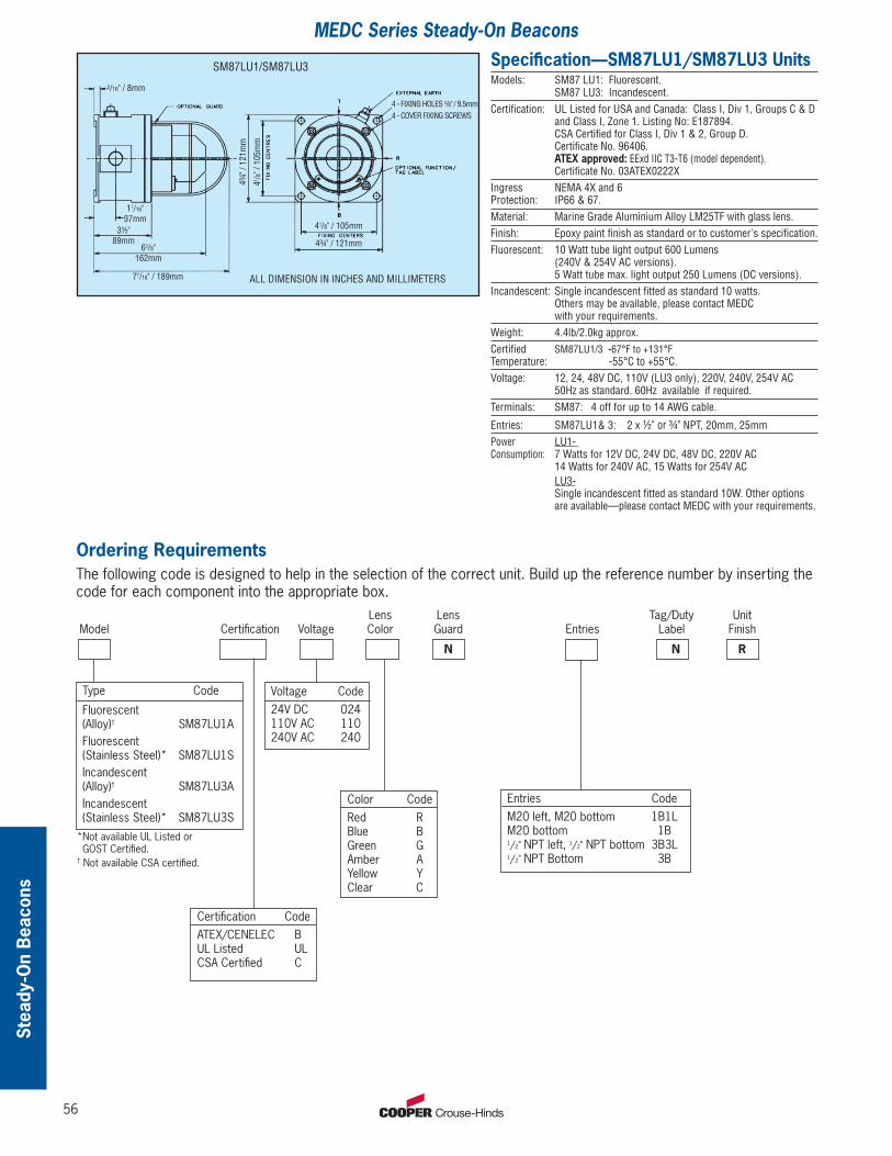
56
MEDC Series Steady-On Beacons
5/16" / 8mm
17/16"37mm
3½"89mm
63/8"162mm
77/16" / 189mm
4¾" /
121
mm
41 /8" /
105
mm
41/8" / 105mm
4¾" / 121mm
4 - FIXING HOLES 3/8" / 9.5mm 4 - COVER FIXING SCREWS
ALL DIMENSION IN INCHES AND MILLIMETERS
Type Code
Fluorescent (Alloy)† SM87LU1A
Fluorescent (Stainless Steel)* SM87LU1S
Incandescent (Alloy)† SM87LU3A
Incandescent (Stainless Steel)* SM87LU3S
Color Code
Red R Blue B Green G Amber A Yellow Y Clear C
Voltage Code
24V DC 024 110V AC 110 240V AC 240
Ordering RequirementsThe following code is designed to help in the selection of the correct unit. Build up the reference number by inserting the code for each component into the appropriate box.
Entries Code
M20 left, M20 bottom 1B1L M20 bottom 1B 1/2" NPT left, 1/2" NPT bottom 3B3L 1/2" NPT Bottom 3B
Certifi cation Code
ATEX/CENELEC B UL Listed UL CSA Certifi ed C
Specifi cation—SM87LU1/SM87LU3 UnitsModels: SM87 LU1: Fluorescent. SM87 LU3: Incandescent.Certifi cation: UL Listed for USA and Canada: Class I, Div 1, Groups C & D
and Class I, Zone 1. Listing No: E187894. CSA Certifi ed for Class I, Div 1 & 2, Group D. Certifi cate No. 96406. ATEX approved: EExd IIC T3-T6 (model dependent). Certifi cate No. 03ATEX0222XIngress NEMA 4X and 6Protection: IP66 & 67.Material: Marine Grade Aluminium Alloy LM25TF with glass lens.Finish: Epoxy paint fi nish as standard or to customer's specifi cation.Fluorescent: 10 Watt tube light output 600 Lumens
(240V & 254V AC versions). 5 Watt tube max. light output 250 Lumens (DC versions).Incandescent: Single incandescent fi tted as standard 10 watts. Others may be available, please contact MEDC
with your requirements.Weight: 4.4lb/2.0kg approx.Certifi ed SM87LU1/3 -67°F to +131°FTemperature: -55°C to +55°C.Voltage: 12, 24, 48V DC, 110V (LU3 only), 220V, 240V, 254V AC 50Hz as standard. 60Hz available if required.Terminals: SM87: 4 off for up to 14 AWG cable.
Entries: SM87LU1& 3: 2 x ½" or ¾" NPT, 20mm, 25mmPower LU1- Consumption: 7 Watts for 12V DC, 24V DC, 48V DC, 220V AC 14 Watts for 240V AC, 15 Watts for 254V AC LU3- Single incandescent fi tted as standard 10W. Other options
are available—please contact MEDC with your requirements.
Lens Lens Tag/Duty Unit Model Certifi cation Voltage Color Guard Entries Label Finish
N N R
SM87LU1/SM87LU3
* Not available UL Listed or GOST Certifi ed.
† Not available CSA certifi ed.
Stea
dy-O
n B
eaco
ns

57
Steady-on Beacons are designed for harsh & hazardous locations where a visual signal is required for tough environmental conditions involving corrosives, water, dust and extreme temperature.
■ Broad range of light source options such as halogen, incandescent, compact & fl uorescent for both indication and illumination
■ Products designed for both conduit wiring and/or cable connection. NPT or metric entries meeting all installation needs
■ Six light color options: Amber, Red, Green, Clear, Blue and Magenta for all signaling conditions
HAZARD•GARD TM
Steady-On Beacons Division 1, Zone 1
The units are UL Listed for Type 3R, 4X and marine installations. The steady-on beacons are available for pendant, wall, stanchion and ceiling mounts, and come in six different globe colors.
Typical industrial and commercial applications include food processing plants, refi neries, mines, tankers, laboratories, sewage treatment plants, off-shore oil rigs, water and fi ltration plants and chemical plants.
The diode polarized steady-on beacon is used in electrically supervised circuitry for life-safety or security applications.
Key Features & Benefits■ Powerful halogen light source for clear visual indication■ Available in six different globe colors—amber,
blue, clear, green, magenta and red■ Factory sealed—no external seals required■ Quick connect—Steady-on beacon fi xture threads onto
mounting module for easy installation■ Small compact size—ceiling mount is 13¾-inch long■ Available in pendant, wall, stanchion and ceiling mount
Certifi cations & Compliances■ Class I, Division 1, Groups C & D■ Class I, Zones 1 & 2, Group IIB■ Class II, Division 1, Groups E, F & G■ Class III■ UL and cUL 1638, UL 1203 and UL 844 Listed■ 1598A Marine Listed (120V AC and 24V DC only)■ cUL Listed C22.2 No. 205■ NEMA 4X watertight, IP 66
Materials & Finishes■ Body, mounting modules and
guard—Copper-free aluminum ■ Globe—Heat and impact-resistant glass■ Gaskets—Silicone ■ External hardware—Stainless steel■ Internal components—Solid-state electronics in a
moisture-resistant and heat-dissipating epoxy■ Epoxy powder coated for corrosion resistance
Ratings■ 120V AC and 24–28V DC■ Operating Current: 0.35 amps at 120V AC (EXSO)
0.8 amps at 24–28V DC (EXDSO, diode polarized)■ Peak Candlepower: 3328
Hub Size■ ¾-inch NPT pendant, ceiling and wall mount■ 1¼-inch NPT stanchion mount
Steady-On B
eacons

58
Description Ambient Max. Temp.
Supply Wire Class I Div. 1, 2 Group C, D Class I, Zone 1Group II B
Class II, Class IIDiv. 1Group E, F, G
Class II, Class IIIDiv. 2Group F, G
EXSO Series Steady-On Beacon Voltage 120V AC
40°C55°C65°C
75°C90°C105°C
T6(85°C)T5(100°C)T5(100°C)
T4A(120°C)T4(135°C) T4(135°C)
T4A(120°C)T4(135°C)T4(135°C)
EXDSO Series Steady-On Beacon—Diode Polarized Voltage 24–28V DC
40°C55°C65°C
75°C90°C105°C
T6(85°C)T6(85°C)T6(85°C)
T4A(120°C)T4(135°C)T4(135°C)
T4A(120°C)T4(135°C)T4(135°C)
Division 1, Zone 1
HAZARD•GARD TM
Steady-On Beacons
O R D E R I N G I N F O R M A T I O N
S T E P 1 Order Steady-On Beacon Type
TE M P E R A T U R E P E R F O R M A N C E D A T A
S T E P 2 Order Mounting Module
Catalog Lens NEMANumber Voltage Color Rating
Explosionproof STEADY-ON BEACONS EXSO301A/120 120V AC Amber 3R, 4X, MarineEXSO301B/120 120V AC Blue 3R, 4X, MarineEXSO301C/120 120V AC Clear 3R, 4X, MarineEXSO301G/120 120V AC Green 3R, 4X, MarineEXSO301M/120 120V AC Magenta 3R, 4X, MarineEXSO301R/120 120V AC Red 3R, 4X, Marine
DIODE POLARIZED Explosionproof STEADY-ON BEACONS EXDSO301A/24 28 24–28V DC Amber 3R, 4X, MarineEXDSO301B/24 28 24–28V DC Blue 3R, 4X, MarineEXDSO301C/24 28 24–28V DC Clear 3R, 4X, MarineEXDSO301G/24 28 24–28V DC Green 3R, 4X, MarineEXDSO301M/24 28 24–28V DC Magenta 3R, 4X, MarineEXDSO301R/24 28 24–28V DC Red 3R, 4X, Marine
Catalog Hub MountingNumber Size Style
EVMP2 3⁄4" PendantEV22 & EV87 WallEV22 3⁄4" CeilingEVMJ4 11⁄4" Stanchion
Stea
dy-O
n B
eaco
ns

59
F A M I L Y TR E E — E X S T R O B E S , R O T A T I N G A N D S T E A D Y - O N B E A C O N S
WALL
EV22 & EV87 3⁄4" HUB
CEILING
EV22 3⁄4" HUB
PENDANT
EVMP2 3⁄4" HUB
STANCHION
EVMJ4 11⁄4" HUB
D I M E N S I O N S — E X S T R O B E S , R O T A T I N G A N D S T E A D Y - O N B E A C O N S
N E T L U M I N A I R E W E I G H T S
Luminaire Housing with Guard 11.0 lbs.
Add mounting modulesPendant 1.0 lbs.Ceiling 1.0 lbs.Wall 4.5 lbs.Stanchion 2.5 lbs.
HOUSING, GLOBE AND GUARD FOREX SERIES STROBE LIGHTS, ROTATING BEACONS, AND STEADY-ON BEACONS
Wall Mount Ceiling Mount
Pendant Mount
Stanchion Mount
Division 1, Zone 1 HAZARD•GARD TM
Steady-On BeaconsSteady-O
n Beacons

60
MEDC Series Visual & Audible Combination Units
Hazardous Locations, Weatherproof DB3 Range
UL Listed to +158°F (+70°C)Ambient Temperature
This range of light weight all GRP, explosionproof horns intended for use in potentially explosive atmospheres has been designed with high ingress protection to cope with the harsh environmental conditions found offshore and onshore in the oil, gas and petrochemical industries.
The fl amepaths, fl are and the body, are manufactured completely from a UV stable glass reinforced polyester. Stainless steel screws and sinter are incorporated thus ensuring a corrosion free product. A tapered fl amepath is used to overcome the problems of assembly of parallel spigot fl amepaths.
Certifications & Compliances■ UL Listed for USA and Canada
– Hazardous locations:
Class I, Div. 2, Groups A, B, C & D
Class I, Zones 1 & 2, AExd IIC T4
– Ordinary locations: Audible-Signal device■ ATEX approved■ NEMA 4X & 6, IP66 & 67 ■ Certifi ed temperature -67°F to +158°F
-55°C to +70°C
Key Features & Benefits■ All GRP corrosion free■ Up to 108dBA output at 10 feet■ Integral volume control■ 27 tones, user selectable■ Horn/Strobe Combination Unit available
Horn/StrobeCombination Unit
Truly a unique product offering with integral visual and audible signaling devices pre-wired for simultaneous output activation.
■ Suitable for Class I, Division 2 applications■ Strobe light and audible tone generator in one
package■ Mounts with ease and facilitates quick fi eld wiring■ UL, cUL, Ex and ATEX for worldwide acceptance
Com
bina
tion
Uni
ts

61
MEDC Series Visual & Audible Combination Units—Hazardous Locations, Weatherproof
Visual & Audible Combination Units—Hazardous Locations, Weatherproof
Certifi cation Voltage Lens/Body Color Ordering Code Catalog # Standard Product Confi guration
ATEX Ex II 2GD 24V DC Red/Red 803130 DB3/XB11B24V RED/REDDB3/XB11, EExd IIB T5, choice of 27 tones, 115dB(A) at 1m output, 29 Cd, no labels, 1 x M20 entry
UL, cUL Listed, Class I, Div 2, Groups C & D
24V DC Red/Natural Black 869200 DB3/XB11UL24V RED/NB
DB3/XB11, GRP material, NEMA 4X & 6, choice of 27 tones, 106dB(A) at 10 feet output, 29 Cd, no labels, 1 x ½" NPT entries
UL, cUL Listed, Class I, Div 2, Groups C & D
24V DC Red/Red 869205 DB3/XB11UL24V RED/RED
UL, cUL Listed, Class I, Div 2, Groups C & D
110V AC Red/Red 869210 DB3/XB11UL110V RED/RED
Certifi cation Voltage Lens/Body Color Ordering Code Catalog # Standard Product Confi guration
Ex II 2GD 24V DC Red/Red 62500009 DB12/XB13 24V RED/RED
IP66 & 67 weatherproof only, 24V DC, GRP sounder interconnected to, on a painted red stainless steel baseplate, a IP66 & 67 weatherproof only, GRP 10 joule beacon
Certifi cation Voltage Lens/Body Color Ordering Code Catalog # Standard Product Confi guration
UL, cUL Listed, Class I, Div 1, Groups C & D
24V DC Red/Red 62500182 DB1P/SM87HXBUL 24V RED/RED24V DC, alloy sounder, interconnected to, painted red stainless steel baseplate, alloy 5 joule beacon
UL, cUL Listed, Class I, Div 2, Groups C & D
24V DC Red/Red 62500183 DB3/SM87HXBUL 24V RED/REDGRP sounder interconnected to, painted red stainless steel baseplate, alloy 5 joule beacon
Com
bination Units

62
MEDC Series Speakers & Tone Generators
Up to 30 Watts Hazardous Locations, Weatherproof
DB16
This range of loudspeakers, intended for use in potentially explosive gas and dust atmospheres, has a power rating of up to 30 Watts and is suitable for use in the harsh environmental conditions found offshore and onshore in the oil, gas and petrochemical industries.
The fl amepaths, fl are and body, are manufactured from a UV stable glass reinforced polyester. Stainless steel screws and mounting stirrup are incorporated to ensure a corrosion-free product.
Primary Applications■ Plant-wide alarm notifi ciaton ■ Audible process alarms
Typical Industries■ Refi neries■ Chemical plants■ Oil and gas exploration■ Marine terminals for transportation & storage
Certifications & Compliances■ UL Listed for USA and Canada
– Hazardous locations:
Class I, Div 2, Groups A, B, C, D*
Class I, Zone 1, AExde IIB/IIC T3/T4*
– Ordinary locations: Signalling Speaker■ ATEX approved■ NEMA 4X & 6, IP66 and IP67■ Certifi ed temperature -67°F to +104°F
-50°C to +40°C
Key Features & Benefits■ GRP corrosion-free fl amepath■ Up to 112dBA at 30 Watts at 10 feet*■ Power tappings via integral transformer■ Ratcheted swivel mounting stirrup■ Stainless steel fi xtures■ 100V line or 8 ohm versions available
*Model dependent
Loudspeakers and tone generators provide high decibel communication for messaging, alert and evacuation in harsh and hazardous locations.
■ Metallic and non-metallic housings■ Explosionproof and Class I, Division 2 horns
and speakers■ Mounting brackets that allow a full 180° swivel■ Products designed for both conduit wiring and/or
cable connection (NPT or metric entries available)■ Selectable tones
Spea
kers
& T
one
Gen
erat
ors

63
MEDC Series Speakers & Tone Generators—Up to 30 Watts Hazardous Locations, Weatherproof
103dB(A) @ 10ft Horn—ExplosionproofDB1Certifi cation ATEXUL Listed for: Class I, Div 1, Groups C & D, Class I, Zone 1
Certifi ed Temperature -13°F to +158°F -25°C to +70°C
Ingress Protection NEMA 4X IP66
Material Alloy
Entries Up to 3 x ½ " or ¾" NPT, 20mm, 25mm
Weight 7.7lb/3.5kg (model dependent)
No. of Tones Multiple tones available
Options: Body color, certifi cation, voltages12–48V DC, 110V AC
108dB(A) @ 10ft Horn—Hazardous LocationsDB3Certifi cation ATEX UL Listed for: Class I, Div 2, Groups A,B,C,D Class I, Zones 1 & 2, AExd IIC T4
Certifi ed Temperature -67°F to +158°F -55°C to +70°C
Ingress Protection NEMA 4X & 6 IP65 & 67
Material Corrosion-free GRP
Entries Up to 2 x ½" NPT, 20mm
Weight 13.2lb/6.0kg
No. of Tones 27 + 5 Programmable
Options: Body color, certifi cation, voltages 12–48V DC, 110V–254V AC
*Single Stage4 wired diode monitored connection—on board diode allows unit to be operated in supervisory mode when monitoring line in reverse polarity.
*Two StageSwitchable unit available in DC versions only either by:(i) Reversing the polarity of the supply, or,(ii) By a 3 wire common +ve system, switching between the –ve lines.
Certifi cation Output Ordering Code Catalog # Standard Product Confi guration
ATEX approved Ex II 2GD 103dB(A) 801001 DB1BA024A1A3NNNR Choice of 6 tones, red fi nish
UL Listed, Class I, Div 2, Groups C & D Up to 96dB(A) @ 10ft 869111 DB1PULA024D1D2NNNR Two-stage alarms, with 26 tones, 24V DC, alloy, red body color, no tag or duty labels, 2 x ¾" NPT entriesUL Listed, Class I, Div 2, Groups C & D Up to 103dB(A) @ 10ft 869115 DB1HPULA024D1D2NNNR
UL Listed, Class I, Div 2, Groups C & D Up to 96dB(A) @ 10ft 17300108 DB1PULA110C1C3NNNR Sounder, 110V AC, 2 x ½" NPT entries, red painted enclosure
Certifi cation Body Color Voltage Type* Ordering Code Catalog # Standard Product Confi guration
UL, cUL Listed, Class I, Div 2, Groups A, B, C, D
Red 12–48V DC Single Stage 869131 DB3UL048N2CNRZ
27 tones, no tag or duty labels, 108 dB(A) output, NEMA 4X & 6, 2 x ½" NPT entries with certifi ed plug
UL, cUL Listed, Class I, Div 2, Groups A, B, C, D
Red 12–48V DC Two Stage 869132 DB3PUL048N2CNRZ
UL, cUL Listed, Class I, Div 2, Groups A, B, C, D
Red 110V AC Single Stage 869135 DB3UL110N2CNRZ
ATEX Ex II 2GD Natural Black 12–48V DC Two Stage 803121 DB3PD048N2BNNZ
27 tones, no tag or duty labels, 2 x M20 entries with one certifi ed plug fi tted
ATEX Ex II 2GD Natural Black 240V AC Single Stage 803122 DB3D240N2BNNZ
ATEX Ex II 2GD Red 12–48V DC Two Stage 803123 DB3PD048N2CNRZ
ATEX Ex II 2GD Red 240V AC Single Stage 803124 DB3D240N2BNRZ
ATEX Ex II 2GD Red 12–48V DC Single Stage 803125 DB3D048N2CNRZ
Speakers & Tone G
enerators

64
MEDC Series Speakers & Tone Generators—Up to 30 Watts Hazardous Locations, Weatherproof
2 - HOLES 5/16" / 8mm DIA
5 ½" / 140mm FIXING CRS
3 1/8" / 79mm
6 7/8" / 175mm DIA
3 1 /8
" / 7
9mm
5 ½
" / 1
40m
m F
IXIN
G CR
S
6 ¾" / 171mm DIA
6 5 /8
" (8½
") / 1
68m
m (2
16m
m)
4 1 /8
" (6"
) / 1
05m
m (1
52m
m)
1 3 /1
6"
30m
m
ALL DIMENSIONS IN INCHES AND MILLIMETERS
Specifi cation—DB1 UnitCertifi cation: UL Listed for Class I, Div. 1. Groups C & D and Class I, Zone 1. UL Listing No. E187688. ATEX Approved: EExd, IIB T3. Cert. No. Baseefa 02ATEX0207 for DB1(P). Cert. No. Baseefa 02ATEX0209 for DB1H(P).
Material: LM25 corrosion resistant alloy with stainless steel cover screws. ABS fl are.
Finish: Epoxy paint fi nish as standard or to customer's specifi cation.
Max Sound Levels: DB1P=93±3dB(A) (86±3dB(A) for 12V DB1). DB1HP=100 ± 3dB(A) @ 10 feet. Note: Sound level is dependent upon the tone selection.
Weight: DB1P 7.7lb/3.5kg approx. DB1HP. 12.3lb/5.6kg approx.
Certifi ed -13°F to +158°F.Temperature: -25°C to +70°C.
Ingress Protection: NEMA 4X, IP66.
Tone Selection: 27 user selectable tones.
Current Consumption: DB1P DB1HP 12V 125mA 900mA 24V 250mA 700mA 48V 250mA – 110V 60mA 200mA
Labels: Duty and tag labels optional.Entries: Up to 3 x ½" or ¾" NPT.Terminals: Suitable to accept up to 12 AWG conductor size.
Tone Tone Frequency Tone Tone Frequency 1 Alt Tones 800/970 Hz at 1/4 sec. 15 554 Hz for 0.1S/440 Hz for 0.1S 2 Sweeping 800/970 Hz at 7 Hz 16 Int 660 Hz 150 mS on 150 mS off 3 Sweeping 800/970 Hz at 1 Hz 17 Int 660 Hz 1.8 sec. on 1.8 sec. off 4 Continuous at 2850 Hz 18 Int 660 Hz 6.5 sec. on 13 sec. off 5 Sweeping 2400–2850 Hz at 7 Hz 19 Continuous 660 Hz 6 Sweeping 2400–2850 Hz at 1 Hz 20 Alt 554/440 Hz at 1 Hz 7 Slow Whoop 21 Int 660 Hz at 7/8 Hz 8 Sweep 1200–500 Hz at 1 Hz 22 Int 2850 Hz 150 mS on 100 mS off 9 Alt Tones 2400/2850 Hz at 2 Hz 23 Sweep 800–970 Hz at 50 Hz 10 Int Tones of 970 Hz at 1 Hz 24 Sweep 2400–2850 Hz at 50 Hz 11 Alt Tones 800/970 Hz at 7/8 Hz 25 3x970 Hz pulses 0.5 off, 1.5 off 12 Int Tone at 2850 Hz at 1 Hz 26 3x2850z pulses 0.5 on/0.5 off, 1.5 off. 13 970 Hz at 1/4 sec. on 1 sec. off 27 Int 3100 Hz 0.3 sec. on 0.7 sec. off 14 Continuous at 970 Hz
Single Stage4 wired diode monitored connection—on board diode allows unit to be operated in supervisory mode when monitoring line in reverse polarity.
Two StageSwitchable unit available in DC versions only either by:(i) Reversing the polarity of the supply, or,(ii) By a 3 wire common +ve system, switching between the –ve lines.
Ordering RequirementsThe following code is designed to help in the se lec tion of the correct unit. Build up the reference number by inserting thecode for each component into the appropriate box.
Entries Code
1 x 20mm A31 x 25mm B31 x 1/2" NPT (UL only) C31 x 3/4" NPT (UL only) D32 x M20 A1A22 x M25 B1B22 x 1/2" NPT C1C22 x 3/4" NPT D1D2
Voltage Code
12V DC 01224V DC 024110V AC 110240V AC 240
Unit Cable Duty TagType Certifi cation Material Voltage Entries Labels Label Features Finish
N N N R
Material Code
Stainless Steel SAlloy A
Cert. Code
ATEX/CENELEC BUL(DBIP & DB & IHP only) UL
UL – available Alloy only. – 12V DC, 24V DC,
48V DC, 110V AC only
DB1DB1H DB1PDB1HP
Spea
kers
& T
one
Gen
erat
ors

65
MEDC Series Speakers & Tone Generators—Up to 30 Watts Hazardous Locations, Weatherproof
Terminals: 4 x 14 AWG (AC), 6 x 14 AWG (DC).Mounting: Stainless steel bracket with rachet facility.Labels: Duty and tag labels optional.Cable Entries: UP TO 2 x ½" NPT.Tone Selection: 27 user selectable tones available.Horn/Strobe Unit: The DB3 may be combined with an MEDC strobe to create
a combined audio/visual alarm. Contact MEDC for price and specifi cation.Two Stage Unit: Switchable between any two tones by either:DB3P (i) Reversing the polarity of the supply, or (ii) by a 3 wire common +ve system, switching between
the two –ve lines. Note: Two stage unit available in DC versions only.3 & 4 Tone unit: Remote 3 & 4 tone unit available—contact sales offi ce for
details.
10 11/16"271mm
Ø 4 5/8" / 117mm Ø 6 11/16" / 170mm
FIXING HOLE Ø ½" / 13mm
FIXING HOLES Ø ALL 11/32" / 8.7mm (2 POS.)
2 x ½" NPT ENTRIES MAX
7 19/32"193mm
1 3/16"30mm
1 3/16"30mm
POSITION 2 IS USED IF ONLY 1 x ½" NPT ENTRY REQUIRED
ALL DIMENSIONS IN INCHES AND MILLIMETERS
2 3/32"53mm
Ordering RequirementsThe following code is designed to help in selection of the correct unit. Build up the reference number by inserting the code for each component into the appropriate box.
Finish Code
Natural Black N Red R
Voltage Code
12V–48V DC 048*110V AC 110*120V AC 120*240V AC 240* DB3P not available in AC version.
Entries Code
1 x 20 mm (EExd) 1B
2 x 20mm (EExd/EExde) 2B
1 x 1/2" NPT (UL only) 1C
2 x 1/2" NPT (UL only) 2C
Unit Type Certifi cation Voltage Labels Entries Options Color
N N
Type Code
EExd DUL Listed UL
Specifi cation—DB3 UnitCertifi cation: UL Listed for USA and Canada – Hazardous locations: Class I, Div. 2, Groups A, B, C, D. Class I, Zones 1 & 2, AExd IIC T4. UL Listing No. E203310. – Ordinary locations: Audible-Signal device. UL Listing No. S8116. ATEX approved: CENELEC EN50014, 18, 19. Cert. No. BAS00ATEX2097X, EExd IIC. Cert. No. BAS00ATEX2098X, EExde IIC. Zones 1 & 2.
Material: Body & horn in anti-static, UV stable, glass reinforced polyester.
Swivel bracket and captive cover screws in stainless steel.
Finish: Body and horn, natural black or epoxy paint coated to client’s color requirements.
Sound Output: DB3 105 ±3dB(A) Typical at 10 feet (tone dependent).
Volume Control: Integral volume control *Nominal Output (dBa) Input Current (mA) 83 50 95 100 98 150 101 200 102 250 104 300 105 350 * Output measured with 24V input voltage. Tone set to
970Hz continuous.Weight: 13.2lb/6.0kg approx.Certifi ed -67°F to +158°F.Temperature: -55°C to +70°C.Ingress Protection: NEMA 4X & 6, IP66 & 67.Voltage: Up to 48V DC Up to 254V AC.CurrentConsumption:
V I 12V DC 760mA 24V DC 380mA 48V DC 190mA 110V AC 135mA 120V AC 124mA 220V AC 68mA 230V AC 65mA 240V AC 62mA 254V AC 59mA
DB3 Unit
Type Details
DB3 Standard unitDB3P Two stage (DC only)
Speakers & Tone G
enerators

66
MEDC Series Speakers & Tone Generators—Up to 30 Watts Hazardous Locations, Weatherproof
Certifi cation Voltage Ordering Code Catalog # Standard Product Confi guration
ATEX Approved ExII 1G 12V DC 805001 DB5B012NRIntrinsically safe, up to 3 x M20 entries via knockouts, no labels, natural red fi nish
ATEX Approved ExII 1G 24V DC 805002 DB5B024NR
FM Approved for Class I,Div 1 & 2, Groups A, B, C, D
24V DC 869150 DB5FM2NRIntrinsically safe, 26 tones, 93 dB(A) output, natural red body color, no tag or duty labels, 2 x 13/16" entries via knockouts
8-25 Watt Speaker—Hazardous LocationsDB4 Certifi cation ATEXUL Listed for: Class I, Div 2, Groups A,B,C,D Class I, Zone 1, AExd IIC T4
Certifi ed Temperature -67°F to +158°F -55°C to +70°C
Ingress Protection NEMA 4X & 6 IP66 & 67
Material Corrosion-free GRP
Output 97 dB(A) at 1W at 10 feet 109 dB(A) at 25W at 10 feet
Entries Up to 2 x ½" NPT, 20mm
Weight 11lb/5.0kg
Options: Body color, transformer, certifi cation, power 25W, 15W, 8W
Up to 93dB(A) @ 10ft Horn—Intrinsically SafeDB5Certifi cation ATEXFM Approved for: Class I, Div 1 & 2, Groups A, B, C, D
Certifi ed Temperature -4°F to +131°F -20°C to +55°C
Ingress Protection NEMA 4 IP65
Material Corrosion-free ABS
Entries Up to 2 x 13/16" via knockouts
Weight 0.7lb/0.3kg
No. of Tones 26
Options: Body color, certifi cation, voltages 12V–240V DC
Certifi cation Power Ordering Code Catalog # Standard Product Confi guration
UL, cUL Listed Class I, Div 2, Groups A, B, C, D
25W 869142 DB425ULX(100)N2CNR 100V line transformer, no labels, 2 x ½" NPT entries, red
fi nish
UL, cUL Listed Class I, Div 2, Groups A, B, C, D
25W 869144 DB425ULX(70)N2CNR 70V line transformer, no labels, 2 x ½" NPT entries, red
fi nish
ATEX Approved ExII 1G 15W 804215 DB415DXN2BNZ100V line transformer, no labels, 2 x M20, one certifi ed plug, fl ameproof enclosure, natural black fi nish
ATEX Approved ExII 1G 25W 804225 DB425DXN2BNZ
Spea
kers
& T
one
Gen
erat
ors

67
MEDC Series Speakers & Tone Generators—Up to 30 Watts Hazardous Locations, Weatherproof
110dB(A) Tone Generator—Weatherproof & Heavy DutyDB15Certifi cation Weatherproof UL Listed for:
Certifi ed Temperature -55°C to +70°C Ingress Protection NEMA 4X & 6
IP66 & 67
Material Corrosion-free GRP
Entries 2 x M20
Weight 2.6kg
No. of Tones 27 + 5 programmable
Options: Body color, two stage alarm (DB15P) version, earth continuity, EOL resistor, voltages 12–48V DC, 110–254V AC
Certifi cation Voltage Type Ordering Code Catalog # Standard Product Confi guration
CE Certifi cation 12–48V DC Two Stage 808110 DB15P048NNWeatherproof, dust-tight, no labels, choice of 27 tones, painted gray fi nish
CE Certifi cation 12–48V DC Two Stage 808115 DB15P048NRWeatherproof, dust-tight, no labels, choice of 27 tones, painted red fi nish
CE Certifi cation 240V AC Single Stage 808120 DB15240NNWeatherproof, dust-tight, choice of 27 tones, natural gray fi nish
CE Certifi cation 240V AC Single Stage 808125 DB15240NRWeatherproof, dust-tight, choice of 27 tones, painted red fi nish
110dB(A) Sounder—Weatherproof & Heavy DutyDB12Certifi cation WeatherproofUL Listed for:
Certifi ed Temperature -55°C to +70°C Ingress Protection NEMA 4X & 6 IP66 & 67
Material Corrosion-free GRP
Entries Up to 3 x 20mm
Weight 1kg
No. of Tones 27 + 5 programmable
Options: Body color, voltages 12V & 24V DC
Certifi cation Voltage Type Ordering Code Catalog # Standard Product Confi guration
CE Certifi cation 115/230V AC Single Stage 808003 DB12115NNWeatherproof, dust-tight, no labels, choice of 27 tones, natural red fi nish, 3 x M20 knockouts
CE Certifi cation 24V DC Two Stage 869155 DB12P024NNWeatherproof, choice of 27 tones, natural red fi nish, 3X M20 knockouts
Speakers & Tone G
enerators

68
30 Watt Speaker — Hazardous & Ordinary LocationsDB16 ULCertifi cation ATEXUL Listed for: Class I, Div 2, Groups C & D/A,B,C,D Class I, Zone 1, AExde IIB T3/IIC T110°C
Certifi ed Ambient -61°F to +90°FTemperature -50°C to +40°C
Ingress Protection NEMA 4X & 6 IP66 & 67
Material Corrosion-free GRP
Output Groups C & D:100dB(A) at 1Watt at 10 ft. 112dB(A) at 30 Watts at 10 ft.Groups A, B, C, D: 3dB(A) less than C & D versions
Entries Up to 2 x ½" NPT or 2 x ¾" NPT, 20mm, 25mm
Weight 12.1lb/5.5kg
Tappings @ 30 Watts 30, 25, 12, 6, 4, 2
Options: Body color, transformer
MEDC Series Speakers & Tone Generators—Up to 30 Watts Hazardous Locations, Weatherproof
Certifi cation Ordering Code Catalog # Standard Product Confi guration
UL, cUL Listed, Class I, Div 2, Groups C & D 28600006 DB16UCXN2MPN Unit suitable for gas Groups A, B, C, D, 70V line transformer, 2 x ½" NPT, one certifi ed plug, natural black fi nish
Spea
kers
& T
one
Gen
erat
ors

69
MEDC Series Speakers & Tone Generators—Up to 30 Watts Hazardous Locations, Weatherproof
8W VERSION7 19/32"
193mm71/4"
184mm
Frequency Response @1W, 10' for 25W Unit
Polar Plot (1kHz) @1W, 10' for 25W unit
Polar plot and frequency response curve for other speakers are available upon request
15W TO 25W VERSIONS
POSITION 2 IS USED IF ONLY1 x ½" NPT ENTRY IS REQUIRED
13/16"30mm
1 3/16"30mm
2 3/32"53mm
Ø 45/8"Ø 117mm
Ø 5 3/8"Ø 137mm
2 x ½" NPT ENTRIES MAX
10 11/16"271mm
Ø 6 11/16"Ø 170mm
FIXING HOLE Ø ½" /13mm
ALL DIMENSIONS IN INCHES AND MILLIMETERS
FIXING HOLES Ø 11/32" / 8.7mm (2 POS.)
DB4
Transformer Code
Yes X*None N
* Std 100V Other valuesavailable, specify voltage.
Max. Rated Power Certifi cation Transformer Labels Entries Color
Color Code
Natural Black N Red R
Power Code
8 watt 815 watt 1525 watt 25
Entries Code
1 x M20 (EExd) 1B2 x M20 (EExd/EExdel) 2B1 x 1/2"NPT (UL lised only) 1C2 x 1/2"NPT (UL lised only) 2C
N
Ordering Requirements
DB4 Unit Specifi cation—DB4 UnitRated Power: 8, 15 or 25 watts RMS continuous (at 77°F).
Certifi cation: UL Listed for USA and Canada – Class I, Div 2, Groups A, B, C, D. – Class I, Zone 1, AExd IIC T4. UL Listing No. E203310. ATEX approved: EN50014, 18, 19. Cert. No.BAS00ATEX2097X, EExd IIC T4/T5. Cert. No. BAS00ATEX2098X, EExDC IIC T4/T5. Zones 1 and 2. Not for use in atmospheres containing carbon disulphide.
Material: Body & horn in anti-static, UV stable, glass reinforced polyester. Swivel bracket in stainless steel. Captive cover screws in stainless steel.
Finish: Body and horn, natural black or epoxy paint coated to client’s color requirements.
Output: 97 dB(A) at 1 watt at 10 feet. 109 dB(A) at 25 watts at 10 feet. Measured in accordance with IEC 268.
Weight: 11lb/5.0kg approx. dependent on model.
Certifi ed Temperature: -67°F to +158°F. -55°C to +70°C.
Ingress Protection: NEMA 4X and 6, IP66 & 67.
Frequency Range: 400Hz to 8kHz.
Voice Coil Impedence: 8 ohms.
Transformer:
Used to vary the rated power by selecting different tappings (see table below).
Transformer Power Tappings 25W 15W 8W
1:2 25.0 15.0 8.0 2:3 12.5 7.5 4.0 3:4 6.0 5.0 2.0 1:3 4.0 4.0 1.5 2:4 2.0 2.0 0.7 1:4 1.0 0.8 0.4
Transformer Options:i) Loop in/Loop out: (4 x 2) terminal tap change (8 terminals).ii) Optional Tapping: 4 terminal tap change with 2 terminals (5 & 6) directly connected to driver (8 ohms).Other tappings & driver impedances available on request.Terminals: 8 x 14AWG Other terminal arrangements available on request.
Mounting: Bracket with ratchet facility.
Labels: Duty and tag labels optional.
Cable Entries: Up to 2 x ½" NPT.
Transformer Tappings
Type Code
EExd DUL lised UL
To specify certifi ed plug, suffi x appropriate code with ‘P’. e.g. 2BP is 2 x M20 entries with one certifi ed plug.
Speakers & Tone G
enerators

70
MEDC Series Speakers & Tone Generators—Up to 30 Watts Hazardous Locations, Weatherproof
DIMENSIONAL DRAWING
2 3/8"60mm
131/32"50mm
2 5/32"55mm
17/8"48mm
Ø 13/16"Ø 21mm
3 21/32"93mm
ALL DIMENSIONS IN INCHES AND MILLIMETERS
Specifi cation—DB5 UnitCertifi cation: 1. FM approved for Class I, Div 1, Groups A, B, C, D. J.I. 3001835. 2. CSA certifi ed to C22.2 Nos. 0, 0.4, 0.5, 25, 30, 205,
Class I, Groups A, B & D, Cert. No. 79122. 3. ATEX approved, EN50014 and EN50020 & EN50284
EExia IICT4. 12/24V version Cert. No. BAS00ATEX 1259 (unit) and 01E2024 (system).
4. HSE(M) to EN50014, EN50020 and EN50303. EExia 1 Cert. No. MECS01ATEX4260 (unit) and
94Y7095 (system).
Material: A.B.S. (Acrylonitrile Butadiene Styrene).
Finish: Available in Red as standard.
Certifi ed -4°F to +131°F.Temperature: -20°C to +55°C.
Weight: 0.7lb/0.3kg.
Entries: Up to 1 x 13/16" on each side via knockouts.
Terminals: 6 off suitable to accept up to 14 AWG.
Sound Output: 90± 3dB(A) at 10 feet for 12V and 24V versions. Typical max value only—variable with tone.
Current Consumption
24V model—14 mA max. nominal. 12V model—12 mA max. nom i nal.
DB5 Unit
Spea
kers
& T
one
Gen
erat
ors

71
MEDC Series Speakers & Tone Generators—Up to 30 Watts Hazardous Locations, Weatherproof
Specifi cation—DB12 UnitMaterial: UV stable glass reinforced polyester. Retained stainless steel cover screws.
Finish: Self colored red as standard or epoxy coated to customer’s specifi cation.
Sound Output: 107± 3dB(A) at 1 meter. Typical value only—variable with tone.
Volume Control: Integral volume control.
*Nominal Output Input Current (dBa) (mA) 92 60 100 70 104 80 109 90
*Output measured with 24V input voltage. Tone set to 2850Hz continuous.
Tone Selection:Single Stage DB12: 27 user selectable tones. Two stage Unit DB12P: Switchable between any two tones by either: (i) Reversing the polarity of the supply, or (ii) by a 3 wire common +ve system, switching between the
two -ve lines. Note: Two stage unit available in DC versions only.
Weight: 1.0 kg. DC, 1.2kg AC
Operating –55°C to +70°C.Temperature:
Ingress Protection: IP66 & IP67.
Voltage: DC: 12V, 24V AC: 115/230V.
Current Consumption: 24V operation 55mA–100mA. 115V operation 85mA–140mA. 12V operation 55mA–90mA. 230V operation 45mA–60mA.
Terminals: 6 x 2.5mm2 .
Labels: Duty and tag labels available.
Cable Entries: Up to 3 x M20 via knockouts.
AFNOR NF S 32 001 compliant version available—contact sales offi ce for details.
Ordering RequirementsThe following code is designed to help in selection of the correct unit. Build up the reference number by inserting the code for each component
into the appropriate box.
Voltage Code
12V DC 012 24V DC 024 115/230V AC 115
Type Details
DB12 Standard UnitDB12P Two Stage (DC only)
DB12 Unit
Unit Type Voltage Labels Color
N N
Speakers & Tone G
enerators

72
MEDC Series Speakers & Tone Generators—Up to 30 Watts Hazardous Locations, Weatherproof
Voltage Code
12V DC 01224V–48V DC 048*110V AC 110*120V AC 120*240V AC 240*DB15P not available in AC version.
Ordering RequirementsThe following code is designed to help in the selection of the correct unit. Build up the reference number by inserting the code for each component in the appropriate box.
DB15DB15P
Specifi cation—DB15 UnitMaterial: Body & horn in UV stable, glass reinforced polyester. Swivel bracket in stainless steel. Cover screws in stainless steel.
Finish: Body and horn, natural gray to RAL 7035 or epoxy paint coated to client’s color requirements.
Sound Output: DB15 117dB(A) Maximum.
Volume Control: Integral volume control *Nominal Output Input Current (dBa) (mA) 100 150 105 250 108 350 110 450 112 550
*Output measured with 24V input voltage. Tone set to 970Hz continuous.
Weight: 2.6kg approx. dependent on model.
Temperature Range: –55°C to +70°C.
Ingress Protection: IP66 and IP67.
Voltage: Up to 48V DC Up to 254V AC
Current Consumption:
Terminals: 4 x 2.5mm2 (AC), 6 x 2.5mm2 (DC).
Earth Continuity: Available.Mounting: Stainless steel bracket with ratchet facility.Labels: Duty and tag labels optional.Cable Entries: 2 x M20 ISO.
V I
12V DC 900mA 24V DC 600mA 48V DC 280mA 110V a.c 150mA 120V AC 175mA 220V AC 93mA 240V AC 86mA 254V AC 80mA
Tone Selection
DB15: 27 user selectable tones available. Additional 5 tones may be programmed.
DB15P (Two stage unit): Switchable between any two of the 27 tones by either:
(i) Reversing the polarity of the supply, or (ii) by a 3 wire common +ve system, switching between
the two –ve lines.
Note: Two stage unit available in DC versions (DB15P) only.
AFNOR NF S 32 001 compliant version available—contact sales offi ce.
Unit Type Voltage Options Color
N N
DB15 Unit
Spea
kers
& T
one
Gen
erat
ors

73
MEDC Series Speakers & Tone Generators—Up to 30 Watts Hazardous Locations, Weatherproof
Specifi cation—DB16 UnitRated Power: 30 Watts RMS continuous (at 77°F/25°C).Certifi cation: UL Listed for USA and Canada – Hazardous locations: Class I, Div 2, Groups C & D, Class I, Zone 1, AExde IIB T3 Class I, Div 2, Groups A, B, C, D, Class I, Zone 1, AExde IIC T110°C UL Listing No. E203310 – Ordinary locations: Signalling Speaker. UL Listing No. 58847 CENELEC EN50014, 18, 19. IIB Version: Cert. No. Baseefa04ATEX0166X ATEX Ex II 2G EExde IIB T3 (Tamb. -50°C to +40°C) IIC Version: Cert. No. Baseefa04ATEX0167X ATEX Ex II 2GD EExde IIC T110°C (Tamb. -50°C to +40°C) Zones 1 and 2.Material: Body & horn in anti-static, UV stable, glass reinforced polyester. Mounting stirrup and fi xtures in stainless steel.Finish: All natural or body and horn can be painted to client’s requirements.Output: Groups C & D Version: Maximum output at 1W at 10 feet is 100dBA Maximum output at 30W at 10 feet is 112dBA Groups A, B, C, D Version: Maximum output at 1W at 10 feet is 97dBA Maximum output at 30W at 10 feet is 109dBAWeight: 12lb/5.5kg approx.Certifi ed Temperature: -67°F to +104°F (-50°C to +40°C).Ingress Protection: NEMA 4X & 6,IP66 & IP67.Frequency Range: 370Hz to 8kHz.Voice Coil Impedence: 8 ohms.Transformer: Used by combining the rated power tappings below.
Polar Plot at 1Khz (IIB Unit)
Polar plot and frequency response curves for other speakers are available upon request.
ALL DIMENSIONS IN INCHES/MILLIMeterS
Frequency Response @ 1W/10 feet for 30W Unit (1/3 Octave Pink Noise)—IIB Unit
DB16
Transformer Code
Yes X*No N
*Std 100V.Other voltages available, specify voltage.
Option Code
Natural Black NRed R
Certifi cation Code
UL (A, B, C, D) UCATEX IIC BC
Entries Code
1 x M20 1B
2 x M20 2B1 x M25 1C2 x M25 2C1 x ½" NPT 1M2 x ½" NPT 2M1 x ¾" NPT 1N2 x ¾" NPT 2NTo specify certifi ed plug, suffi x appro-priate code with ‘P’, e.g. 2BP is 2 x M20 entries with one certifi ed plug.
Ordering RequirementsThe following code is designed to help you in the selection of the correct unit. Build up the reference number by inserting the code for each feature into the appropriate box.
Unit suitable for gas groups.
Certifi cation Transformer Options Entries Finish
N
TransformerTappings
Power (W)
1:22:33:41:32.41.4
302512642
Terminals: 8 x 2.5mm2.Earth Continuity: Available via optional earthing stud or by internal earth plate.Mounting: Via stirrup with ratchet facility.Labels: Optional stainless steel tag and duty labels.Cable Entries: Up to 2 x ½" NPT or 2 x ¾" NPT Iinto termination chamber, 20mm, 25mm
Transformer Tapping Options:
(i) Loop in/loop out (4 x 2) power tap change; 8 terminals
(ii) Loop in/loop out (2 x 2) 8 ohm; 4 terminals.
DB16 Unit
Speakers & Tone G
enerators

74
The Flex-Tone ETH & ETHD are heavy-duty, explosionproof tone-selectable signaling devices. Both are designed for Class I, Division 1, Groups B, C & D areas and are ideal for signaling warning or emergency conditions within process or manufacturing facilities.
The Flex-Tone ETH tone-selectable signalers (ETH655 & ETH855) are for use on standard electrical circuits and accept up to two contact closures providing two audible output signals selected from 55 tone choices. The ETHD855 tone-selectable signaler is used for applications (e.g., mining, tankers, laboratories) requiring electrical supervision of circuits.
The Flex-Tone ETH remote speaker amplifi er (ETH645 & ETH845) is a speaker/amplifi er for remote
mounting and designed for use with the Flex-Tone (ETH640 & ETH840) Panel Control Signal Generator.
The Control Panel Generator is mounted in a Division 2 area while the Flex-Tone ETH remote speaker
amplifi ers are remotely mounted in Division 1 areas. The ETH remote speaker amplifi er (ETH645 &
ETH845) operates from local available power sources. Because the Flex-Tone ETH remote speaker
amplifi er is available in multiple AC and DC voltages, your customer can mix and match speakers
throughout their facility using available line power.
The Flex-Tone Panel Control Signal Generator (ETH640 & ETH840)
controls a synchronous signaling sound to all ETH remote speaker
amplifi ers. It is ideal for applications where simultaneous signaling
of a high decibel signal is needed. The Flex-Tone Panel Control
Signal Generator generates 27 sounds. Four tones may be
activated from fi eld-wired, normally open contacts, or a 24V DC or
120V AC external voltage source such as an output of a PLC.
Flex-Tone™ SeriesNew Audible Products
Spea
kers
& T
one
Gen
erat
ors

75
Description Catalog Reference
Operating Voltage
Operating Circuit
Flex-Tone heavy-duty tone-selectable signaling device
ETH655 & ETH855
24V DC, 36V DC, 24AC/DC, 120V AC, 240V AC, 125V DC,250V DC
Standard electrical circuits, AC or DC operation.
Heavy-duty tone-selectable signaling device, diode polarized
ETHD855 20–31V DC Standard electrical circuits or auxiliary fi re or warning circuits requiring electrical supervision.
Flex-Tone Panel Control Signal Generator Suitable for Div. 2 areas only
ETH640 & ETH840 24V DC, 24AC/DC 120V AC, 240V AC, 125V DC, 250V DC
Standard electrical circuits, AC or DC operation and communication to remote speaker amplifi ers can be connected to a network by RS485 serial protocol.
Flex-Tone remotespeaker/amplifi er for use with Flex-Tone Panel Control Signal Generator
ETH645 & ETH845 24V DC, 24AC/DC, 120V AC, 240V AC, 125V DC, 250V DC
Standard electrical circuits, AC or DC operation.
P R O D U C T B R E A K D O W N — N E W A U D I B L E P R O D U C T S , C L A S S I D I V I S I O N 1
Industries
■ Offshore platforms and drilling rigs ■ Refi neries, chemical and petrochemical plants■ Pharmaceutical plants ■ Food and Beverage plants■ Waste water and sewage treatment plants■ Pulp and paper mills
Uses
■ Communication■ Security alert■ Safety signaling in industrial and process facilities■ Emergency evacuation signaling■ Messaging
Flex-Tone SeriesNew Audible Products
A P P L I C A T I O N — F L E X - T O N E E X P L O S I O N P R O O F A U D I B L E S I G N A L S A R E U S E D
Speakers & Tone G
enerators

76
Cooper Crouse-Hinds Flex-Tone Series Electronic Signals are explosionproof, heavy-duty, tone-selectable
signaling devices capable of producing volume-controlled,
high-decibel tones. Certifi ed for use in Class I, Division 1,
Group B, C & D applications, the Flex-Tone Series is ideal
for signaling warning or emergency conditions.
The Flex-Tone ETH855 accepts up to two contact
closures and delivers two audible output signals selected
from 55 available tones. The two tones are selected by
setting miniature switches within the unit. One of the tones
can be assigned a priority status to override the other tone.
The Flex-Tone ETHD855 is diode polarized for
applications requiring electrical supervision of signaling
circuit fi eld wiring. The signal delivers one audible output
signal selected from the 55 tones available.
Primary Applications■ For use where a high-decibel sound is required for
alert or evacuation in hazardous locations
Key Features & Benefi ts■ Heavy duty zinc cast construction.■ 55 tone capacity—No additional tone
modules needed■ Internal volume control with internal potentiometer.■ Corrosion-resistant heat-fl owed epoxy fi nish■ Supplied with factory sealed ½-inch threaded fi tting
for quick installation■ Speaker can swivel 180° vertically or horizontally
depending on orientation of mounting bracket■ Mounts onto any surface using only three bolts■ 30-inch numbered wire leads
Certifi cations & Compliances■ Class I, Division 1, Groups B, C & D■ Class II, Division 1, Groups E, F & G■ Class III■ UL and cUL 464 and 1203 Listed
Materials & Finishes■ Body—Heavy-duty zinc cast construction ■ External hardware—Stainless steel Ratings■ 24V DC, 36V DC, 125V DC, 250V DC,
24V AC, 120V AC & 240V AC (ETH)■ 20–31V DC (ETHD)
Output Sound Pressure ■ 109 decibel (dBA) output
ExplosionproofElectronic Signal Stand-Alone Unit
O R D E R I N G I N F O R M A T I O N
Catalog Signal OFF Signal ONNumber Voltage Standby Current (Amps) Operating Current (Amps)
Explosionproof, TWO OUTPUT ETH855/24 24V DC 0.061 0.470ETH855/36 36V DC 0.077 0.600ETH655/24 24V AC, 50/60Hz 0.250 1.320ETH655/120 120V AC 0.088 0.260ETH655/240 240V AC 0.091 0.190ETH855/125 125V DC 0.031 0.130ETH855/250 250V DC 0.019 0.070
DIODE POLARIZED, Explosionproof, SINGLE OUTPUT FOR FIRE ALARM APPLICATIONS Meets min. 75 dBA for fi re alarm indicationETHD855/24 20–31V DC 0.061 0.400
Division 1Flex-Tone SeriesAudible Signaling
Spea
kers
& T
one
Gen
erat
ors

77
O R D E R I N G I N F O R M A T I O N
Catalog Signal OFF Signal ONNumber Voltage Standby Current (Amps) Operating Current (Amps)
Explosionproof REMOTE SPEAKER/AMP ETH845/24 24V DC 0.061 0.470 ETH645/24 24V AC, 50/60Hz 0.250 1.320ETH645/120 120V AC 0.088 0.260ETH645/240 240V AC 0.091 0.190ETH845/125 125V DC 0.031 0.130ETH845/250 250V DC 0.091 0.070
* ETH845 Series Remote Speaker/Amplifi ers must be used with Cooper Crouse-Hinds Flex-Tone Panel Control Signal Generator on the following page.
ETH845 Series Remote Speaker/Amplifi ers accept a 10V AC audio signal from Flex-Tone Panel Control Signal Generator.
Cooper Crouse-Hinds Flex-Tone Series Explosionproof Remote Speaker/Amplifi er is designed for remote
mounting in Division 1 areas where simultaneous high-
decibel signaling is required.
Used in connection with the Panel Control Signal Generator,
the Flex-Tone ETH845 operates directly from local power
sources, allowing remote speaker/amplifi ers of different
voltages to be connected within the same system. Available
in both AC and DC voltages, the Flex-Tone 3 can be mixed
and matched throughout an application using the available
line power.
ETH845 Series Remote Speaker/Amplifi ers must be used with Cooper Crouse-Hinds Flex-Tone Panel Control Signal Generator on the following page.
Primary Applications■ For use where simultaneous signaling of a high-
decibel sound is required for alert or evacuation in hazardous locations.
Key Features & Benefi ts■ Heavy duty zinc cast construction.■ Individual volume control.■ Corrosion-resistant heat-fl owed epoxy fi nish.■ Supplied with factory sealed 1⁄2-inch threaded fi tting
for quick installation.■ Speaker can swivel 180° vertically or horizontally
depending on orientation of mounting bracket.■ Mounts onto any surface using only three bolts.■ 30-inch numbered wire leads.
Certifi cations & Compliances■ Class I, Division 1, Groups B, C & D■ Class II, Division 1, Groups E, F & G■ Class III■ UL and cUL 464 and 1203 Listed
Materials & Finishes■ Body—Heavy-duty zinc cast construction ■ External hardware—Stainless steel
Ratings■ 120V AC, 240V AC, 125V DC and 250V DC
Output Sound Pressure■ 109 decibel (dBA) output
ExplosionproofRemote Speaker /
Amplifi er
Division 1Flex-Tone SeriesAudible Signaling
Speakers & Tone G
enerators

78
Cooper Crouse-Hind/MEDC Flex-Tone Series Panel Control Signal Generator controls and initiates a synchronous signaling sound
from all Flex-Tone 3 remote Speaker/Amps installed in a system. The
Panel Control Signal Generator is mounted in a Division 2 area, while
controlling the Flex-Tone 3 Speaker/Amps that are remotely mounted in
Division 1 areas.
The Panel Control Signal Generator produces 27 sounds. Four tones
may be activated from fi eld-wired, normally open contacts, or a 24V DC
or 120V AC external voltage source such as an output from a PLC.
O R D E R I N G I N F O R M A T I O N
Catalog Input Card Signal OFF Signal ONNumber Voltage Activation Voltage Standby Current (Amps) Operating Current (Amps)
PANEL CONTROL SIGNAL GENERATOR ETH840/24E74 24V DC 24V DC 0.10 0.74ETH640/24E13 24V AC, 50/60Hz 24V DC 0.10 1.30ETH640/120E36 120V AC, 50/60Hz 24V DC 0.10 0.36ETH640/120M38 120V AC, 50/60Hz 120V AC 0.10 0.38ETH640/120E32 120V AC, 50/60Hz 24V DC 0.10 0.32ETH640/240E20 240V AC, 50/60Hz 24V DC 0.10 0.20ETH840/125E21 125V DC 24V DC 0.10 0.21ETH840/250E10 250V DC 24V DC 0.02 0.10ETH640/120M31 120V AC, 50/60Hz 120V AC 0.10 0.31ETH640/240M20 240V AC, 50/60Hz 120V AC 0.10 0.20ETH840/125M20 125V DC 120V AC 0.10 0.20ETH840/250M10 250V DC 120V AC 0.02 0.10ETH640/120R31 120V AC, 50/60Hz RS485 0.10 0.31ETH640/240R20 240V AC, 50/60Hz RS485 0.10 0.20ETH840/125R20 125V DC RS485 0.10 0.20ETH840/250R10 250V DC RS485 0.02 0.10
* Flex-Tone Panel Control Signal Generator must be used with Cooper Crouse-Hinds ETH845 Remote Speaker/Amps on page 77.
Primary Applications■ Hazardous area applications calling for high-decibel
output with simultaneous signal delivery over all speakers installed in a system
■ Emergency warning systems, plant evacuation alarms, security intrusion alarms, process monitoring, shift start and dismissal horns, and paging signals
Key Features & Benefi ts■ 27 tone capability—No additional tone
modules needed■ Centralized programmable tone selection■ PLC compatible■ System-wide priority tone■ 24V DC battery backup terminals■ Short circuit protected
Certifi cations and Compliances■ Class I, Division 2, Groups A, B, C & D■ Class II, Division 2, Groups F & G■ Class III■ UL 464 and 1604 Listed■ cUL C22.2 No. 205 ■ CE Marked—Cenelec LV & EMC Directives■ NEMA 3R, IP 44
Materials & Finishes■ Zinc-cast construction with an epoxy powder
coat fi nish
Ratings■ See table below
Division 1Flex-Tone SeriesAudible Signaling
Spea
kers
& T
one
Gen
erat
ors

79
D I M E N S I O N S — F L E X - TO N E S E R I E S A U D I B L E S I G N A L I N G D E V I C E S
Division 1Flex-Tone SeriesAudible Signaling
Speakers & Tone G
enerators

80
The MEDC heat detector has been designed for use in hazardous environments. These units are suitable for fi re alarm and/or suppression systems in offshore and onshore applications including paint spray booths, fl ammable material stores, turbine rooms, extract ductwork and other hazardous areas throughout the oil & gas, petrochemical and process industries.
Comprising a Fenwal rate-compensated detector with all-stainless steel external construction, mounted to either a type SM87 marine grade alloy enclosure (EExd version) or JB10 corrosion-free GRP enclosure (EExia, EExem/UL versions). The contact in the detector CLOSES at alarm temperature.
To select appropriate temperature setting see specifi cation on reverse.
Primary Applications■ Compressor turbine/generator skids■ Switchgear or motor control status rooms■ Process tank areas or transmission lines
Typical Industries■ Power generation■ Nuclear plants■ Chemical processing■ Upstream/downstream oil & gas
Certifi cations & Compliances■ Zone 0, Zone 1 and Zone 2
■ EExia IIC T4/T6, EExd IIB T3/T6 orEExem II T6
■ ATEX approved – Ex II 1G (EExia) – Ex II 2G (EExd/EExem)
■ BASEEFA certifi ed
■ UL listed for USA and Canada – Class I, Div 2, Groups A, B, C, D
■ GOST ‘R’ & ‘K’ certifi ed
■ Chinese (CQST) certifi ed
■ IP66 & IP67
■ Certifi ed temperature:-20°C to +125°C (EExd)*-20°C to +55°C (EExem/UL)-55°C to +55°C (EExia)
■ Stainless steel probe
■ Detector temperature settings:60°C to 385°C, (140°F to 725°F)
■ Marine grade Alloy or GRP enclosure
■ Optional guard
*Model dependent
Explosionproof & Intrinsically SafeMEDC SeriesHeat Detectors
EExd version (optional guard)
EExia/EExem/UL versions (optional guard)
Now VNIIPO Approved
Now UL Listed
Hea
t Det
ecto
rs

81
MEDC Series Heat Detectors—Control & Distribution
Heat Detector — Explosionproof & Intrinsically SafeHD1Certifi cation ATEX, GOST ‘R’ & ‘K’, ChineseFlameproof ATEX Ex II 2G, EExd IIB T6Increased Safety ATEX Ex II 2G, EExem II T6Intrinsically Safe ATEX Ex II 1G, EExia IIC T6
Certifi ed Ambient Temperature -20°C to +125°C EExd (T3) ATEX/GOST ‘R’ -20°C to +55°C EExd (T6)/EExem -55°C to +55°C EExia
Ingress Protection IP66 & 67
Material Marine Grade Alloy (EExd) Corrosion-free GRP (EExia/EExem)
Temperature Settings 140°F to 725°F (60°C to 385°C)
Entries 2 x M20
Weight 1.1–2.0kg (model dependent)
Options: Enclosures, color, tag and duty labels, temperature setting
EExia/EExem
EExd
HD1 EExd
HD1 EExia/EExem
Compensated Heat Detector with Guard Fitted Natural Black Finish
Certifi cation Temperature Setting (°F) (°C)
Tolerance (°F) (°C)
Color CodeDetector Tip
Ordering Code Catalog #
UL, cUL, Class I, Div 2, Groups A, B, C, DClass I, Zone 2, IIC
140 60 +7/-8 ±4 Black 46500152 HD1ULE140GN
160 71 +7/-8 ±4 Black 46500153 HD1ULE160GN
190 88 +7/-8 ±4 White 46500154 HD1ULE190GN
225 107 +7/-8 ±4 White 46500155 HD1ULE225GN
275 135 ±10 ±6 Blue 46500156 HD1ULE275GN
325 163 ±10 ±6 Red 46500157 HD1ULE325GN
360 182 ±10 ±6 Red 46500158 HD1ULE360GN
450 232 ±15 ±8 Green 46500159 HD1ULE450GN
To select appropriate temperature settings, choose detector at 56°C (100°F) above maximum ambient temperature.
Certifi cation Standard Product Confi guration Ordering Code Catalog #
ATEX EExd 140°F detector, marine grade alloy enclosure, painted gray 465607 HD1BD140NG
ATEX EExd 160°F detector, marine grade alloy enclosure, painted gray 465602 HD1BD160NG
ATEX EExd 190°F detector, marine grade alloy enclosure, painted gray 465603 HD1BD190NG
ATEX EExd 225°F detector, marine grade alloy enclosure, painted gray 465614 HD1BD225NG
ATEX EExd 275°F detector, marine grade alloy enclosure, painted gray 465609 HD1BD275NG
ATEX EExd 325°F detector, marine grade alloy enclosure, painted gray 465605 HD1BD325NG
ATEX EExd 360°F detector, marine grade alloy enclosure, painted gray 46500043 HD1BD360NG
ATEX EExd 450°F detector, marine grade alloy enclosure, painted gray 465601 HD1BD450NG
ATEX EExd 600°F detector, marine grade alloy enclosure, painted gray 46500045 HD1BD600NG
ATEX EExd 725°F detector, marine grade alloy enclosure, painted gray 46500104 HD1BD725NG
ATEX EExem 140°F detector, GRP enclosure, natural black 46500026 HD1BE140NN
ATEX EExem 160°F detector, GRP enclosure, natural black 465301 HD1BE160NN
ATEX EExem 190°F detector, GRP enclosure, natural black 465305 HD1BE190NN
ATEX EExem 225°F detector, GRP enclosure, natural black 465304 HD1BE225NN
ATEX EExem 275°F detector, GRP enclosure, natural black 46500031 HD1BE275NN
ATEX EExem 325°F detector, GRP enclosure, natural black 465306 HD1BE325NN
ATEX EExem 360°F detector, GRP enclosure, natural black 46500072 HD1BE360NN
ATEX EExem 450°F detector, GRP enclosure, natural black 465303 HD1BE450NN
Heat D
etectors

82
MEDC Series Heat Detectors—Control & Distribution
EExd version
EExia/EExem/UL versions
Specifi cation—HD1 UnitCertifi cation: CENELEC EN50014, 19 & 28. EExd IIB T6 (T3 at +125°C), Cert.No. Baseefa 03ATEX0447. EExia IIC T6 (T4 with diodes/resistors), Cert. No. Baseefa 03ATEX0427. EExem II T6, Cert. No. Baseefa 03ATEX0428. UL listed for USA and Canada – Class I, Div 2, Groups A, B, C & D. UL Listing No. E252920, GOST ‘R’ & ‘K’ Certifi cation: Exd, Exi & Exem versions. Russian Fire Alarm (VNIIPO) approved. Chinese Certifi cation: CQST – Exd, Exi & Exem versions.Material: Detector: 316 stainless steel Enclosures: EExd – LM25 marine grade alloy. EExia/EExem/UL – GRP (anti-static). Stainless steel cover screws. Optional Guard: 316 stainless steel.Finish: Detector: Sand blasted. Enclosures: EExd – Epoxy painted gray as standard or to
customer’s specifi cation. EExia/EExem/UL – Self colored black or epoxy painted to
customer’s specifi cation.Weight: EExd, 2kg. EExia/EExem/UL, 1.1kg.Certifi ed: –20°C to +125°C EExd (T3) ATEX & GOST ‘R’ only.Temperature: –20°C to +55°C EExd (T6)/EExem/UL, –55°C to +55°C EExia.Ingress Protection: IP66 & IP67.Operation: The detector contact is normally open and CLOSES at alarm temperature.Listed Temperature To select appropriate temperature settings, choose detector at 56°CSettings: (100°F) above maximum ambient temperature.
Temperature Setting Tolerance Color Code (°F) (°C) (°F) (°C) Detector Tip 140 60 +7/-8 ±4 Black 160 71 +7/-8 ±4 Black 190 88 +7/-8 ±4 White 225 107 +7/-8 ±4 White 275 135 ±10 ±6 Blue 325 163 ±10 ±6 Red 360 182 ±10 ±6 Red 450 232 ±15 ±8 Green 600 316 ±20 ±11 Orange 725 385 ±25 ±14 Orange
Contact Rating: EExd/EExem/UL: 125V AC – 5A, 125V DC – 0.5A, 48V DC – 1A. EExia: 30V – 300mA.Terminals: 6 x 4mm2 (BK6).Labels: Optional stainless steel tag and duty labels.Cable Entries: 2 x M20 ISO (ATEX/Exd/Exe/Exi versions) 2 x ½" NPT via adaptors (UL version).Resistor: Series & EOL ressistor (maximum total 2) minimum value (each) 470Ω – only
available Exd & Exi versions.Diodes: Up to 2 off available in Exd, Exi & UL versions—contact sales offi ce.
Type Code
Exd D Exe E Exi I UL U*
* Select this option for UL listed.
Temp °F Code
140 140
160 160
190 190
225 225
275 275 325 325
360 360
450 450
Finish Code
Natural Black (EExe/EExi/UL only) N Gray G
Certifi cation Code
ATEX B UL listed UL
Model Certifi cation Type Temp. Settings Options Enclosure Finish
HD1 N
HD1 Unit
Ordering RequirementsThe following code is designed to help in the selection of the correct unit. Build up the reference number by inserting the code for each component in the appropriate box.
Hea
t Det
ecto
rs

83
Initiating Device
1. Smoke alarm
2. Circuit resistance goes to 0 ohms when fi re alarm activates
2a. Fire AlarmPanel
2. Alarm mode
4. Polarity reverses in alarm mode
5. Diode in the strobe light is forward biased in alarm mode and conducts electricity
6. Notifi cationdevice
Diode Polarized Technology: Also known as supervisory diode circuit for use in fi re alarm applications
or other critical warning requirements such as industrial hazards and process control emergency
indication. Units with a supervisory diode typically have four wires.
In fi re alarm technology, when a fi re-initiating device such as a smoke alarm is activated, circuit
resistance on the initiating circuit goes to zero. The fi re alarm panel goes into alarm mode when it
senses the resistance at zero. See diagram below.
With the fi re alarm panel in alarm mode, voltage polarity is reversed (under normal operation the diode
is reversed biased blocking voltage) on the circuit powering the notifi cation device or strobe light. The
strobe light is activated (diode is now forward biased allowing voltage through) when it senses a change
in polarity. All NFPA approval visual indication for fi re alarm must use a clear lens.
Terms used in fi re alarm circuitsInitiating Device Circuits (IDC) connect the fi re alarm panel to the system components that detect the
fi re. System components such as smoke detectors, manual pull stations, and water fl ow switches.
Appliance Circuits connect the fi re alarm panel to the signaling devices such as strobe lights, bells,
horns and speakers that alert building occupants of a fi re.
Diode Polarized Technology
General Inform
ation

84
P R O T E C T I V E S I G N A L I N G S Y S T E M W I R I N G P R A C T I C E S
INTRODUCTION
The installation of fi re alarm system wiring is similar in many respects to any other low-voltage system wiring. Because the nature of the system affects life and property, additional measures are required during installation to ensure the system is operational at all times. The most sophisticated of control panels will not operate properly if the fi eld wiring is installed incorrectly. It is the goal of this section to explain why correctly installed fi eld wiring is vital in the operation of a fi re alarm system, and how to recognize proper and improper installations. The process requires four basic steps: SELECT the proper cable for the application; INSTALL the cable properly; TEST the cable to make sure it is free of shorts, opens, and ground faults; and TERMINATE the cable properly.
BASIC CIRCUIT SUPERVISION
There are two types of circuit supervision widely used in fi re alarm systems today. Direct Current (DC) continuity supervision is used extensively on small systems. Large fi re alarm systems use sophisticated electronic multiplex circuitry and “electronic questions and answers” to supervise fi eld wiring and devices.
Figure 1 shows a simplifi ed fi re alarm panel supervising a single Initiating Device Circuit or zone using Direct Current (DC) continuity supervision. The supervisory current from the battery fl ows through terminal #1, the fi eld wiring, the EOL resistor, terminal #2 of the control panel through a second resistor, and returns to the battery. The internal resistor and EOL resistor have equal resistance values. The voltage at the zone test point V
Z is measured by voltage
sensing circuits. As long as the supervisory current fl ows through the EOL resistor, the voltage at V
Z is one half the supply voltage V
S
and the voltage sense circuitry generates a normal panel response.
Figure 2 shows when a smoke detector or pull station operates, it effectively puts a short across terminals #1 and #2. This brings the zone test point voltage V
Z up to the supply voltage V
S. When
the voltage sense circuitry sees VZ = V
S, it generates an alarm
response, such as ringing a bell.
NORMAL INITIATING DEVICE CIRCUIT (IDC)
INITIATING DEVICE CIRCUIT (IDC) IN ALARM CONDITION
Figure 1
Figure 2
Fire AlarmSystems
Gen
eral
Info
rmat
ion

85
Figure 3 shows should the fi eld wiring open, the supervisory current no longer fl ows through the fi eld wiring and EOL resistor and V
Z goes to zero. When the voltage sense circuitry sees V
Z =
0, it generates a trouble response, such as sounding the trouble buzzer.
Figure 4 shows an improperly wired Initiating Device Circuit. Because the supervisory current is not forced to fl ow through the top and bottom branches, the break in the top branch doesn’t interrupt the supervisory current, and there is no indication of the trouble. Should the top device detect a fi re, the signal would never reach the control panel. Note that the lower device would send a fi re alarm signal but would not send a trouble signal to the fi re alarm panel, a classic symptom of miswiring.
Large multiplex systems use sophisticated electronics that employ a system of “electronic questions and answers” to verify circuit viability. The control panel knows the “names” of all the devices that should be connected to it. After asking a “question” of each name or device on its list, the control panel must receive an answer from that device only. Failure to receive the proper answer causes the panel to generate a trouble signal. Because multiplex systems do not depend on the wiring path for supervision, some multiplex systems permit limited branch wiring or T-taps.
OPEN INITIATING DEVICE CIRCUIT (IDC)
INCORRECTLY WIRED INITIATING DEVICE CIRCUIT (IDC)
Figure 3
Figure 4
Fire AlarmSystems
General Inform
ation

86
When using decibels, to double the loudness you only have to add 3 dB. For example, if a signal is rated at 85 dB at 10 feet, then a signal twice as powerful would be rated at 88 dB at 10 feet. The table below illustrates how the sound pressure level changes with distance under good conditions.
THINGS TO CONSIDER WHEN SPECIFYING AUDIBLE SIGNALS. 1. Defi ne the function of the signal: For example, general alarm, emergency, shift dismissal, paging, and process indication.
2. Uniform sound distribution: A larger number of smaller devices evenly distributed throughout the signaling area are better than a single large/loud device.
3. Ambient Sound: The signal should exceed the surrounding ambient noise by 6 decibels.
4. Size of the area: Common sense applies here, the larger the area, the louder the signal required and/or the greater the number of signaling devices required.
5. Mounting: As with all our products, consider mounting constraints and choose a suitable device and mount. Horns and speakers perform best when rigidly mounted to the structure.
S O U R C E I N D B F E E T F R O M S O U R C E
100 dB 10
94 dB 20
90 dB 30
88 dB 40
82 dB 80
Sound BasicsG
ener
al In
form
atio
n

87
Glossary and Explanations:
Candela Seconds: Actual light energy contained in a pulse of light. Used to specify the minimum require-
ments for light output from a fl ashing light. Candela seconds is a relative measure of how bright a fl ash of
light will appear to a human eye. (Candela: The intensity base unit for light.) Candela seconds and candela
effective (below) are the primary metrics by which to compare fl ashing warning lights.
Candela Effective or Effective Candlepower: Equates the brightness of a fl ashing light source to
the brightness of a steady burning source. If a fl ashing light has a candela effective rating of 100 then it
will be visible at the same distance as a 100 candela steady burning source. Candela effective is used
in specifying intensities of fl ashing light sources because it compares fl ashing warning lights with steady
burning light sources.
Peak Candela or Peak Candlepower: The maximum light intensity generated by a fl ashing light during
its light pulse.
Strobe, Principle of Operation: A strobe light consists of a xenon strobe lamp, power supply, energy
storage capacitor and a trigger circuit.
The strobe bulb consists of a glass tube that has and electrode at either end called an anode (+) and
cathode (-). The tube is fi lled with xenon gas and a trigger element is applied to the outside of the bulb.
The trigger element could be a wire wrapped around the tube, a conductive paint stripe along one side of
the glass bulb or clear conductive coating over the outside of the tube.
The power supply charges a large capacitor with the voltage needed to “strike” the bulb and is applied to
the anode and cathode. The voltage is generally between 200 and 500 VDC depending on the design of
the light.
The trigger circuit applies 7,000 to 10,000 volts (low current) to the trigger element of the bulb causing
the xenon gas to ionize and discharge the capacitor.
The energy excites the xenon gas and produces a very short burst of high intensity white light.
Watts (Power): joules x fl ash rate
Joules = Watts Flash Rate
Joules = (Capacitance in Microfareds) lamp voltage2
1000
2
Things that impact light output:
■ Physical shape of the strobe lamp and arrangement within lens
■ Effi ciency of the strobe lamp—its ability to turn electricity into a bright white light
■ Color of the lens
■ Size and effi ciency of the lens
( )
General Inform
ation

88
Index by Ordering Code
Ordering Code Page Number
326023 ......................................................51
465301 ......................................................81
465303 ......................................................81
465304 ......................................................81
465305 ......................................................81
465306 ......................................................81
465601 ......................................................81
465602 ......................................................81
465603 ......................................................81
465605 ......................................................81
465607 ......................................................81
465609 ......................................................81
465614 ......................................................81
762311 ......................................................55
800001 ......................................................12
800002 ......................................................12
800003 ......................................................12
800004 ......................................................12
800005 ......................................................12
800006 ......................................................12
800007 ......................................................12
800010 ......................................................11
801001 ......................................................63
803121 ......................................................63
803122 ......................................................63
803123 ......................................................63
803124 ......................................................63
803125 ......................................................63
803130 ......................................................61
804215 ......................................................66
804225 ......................................................66
805001 ......................................................66
805002 ......................................................66
808003 ......................................................67
808110 ......................................................67
808115 ......................................................67
808120 ......................................................67
808125 ......................................................67
811101 ......................................................27
811102 ......................................................27
811103 ......................................................27
811104 ......................................................27
812101 ......................................................30
812102 ......................................................30
812103 ......................................................30
812104 ......................................................30
Ordering Code Page Number
813005 ......................................................27
813006 ......................................................27
813007 ......................................................27
813008 ......................................................27
813009 ......................................................27
813101 ......................................................31
813102 ......................................................31
813103 ......................................................31
813104 ......................................................31
814001 ......................................................30
814002 ......................................................30
869101 ......................................................12
869105 ......................................................11
869111 ......................................................63
869115 ......................................................63
869121 ......................................................30
869122 ......................................................30
869125 ......................................................30
869126 ......................................................30
869131 ......................................................63
869132 ......................................................63
869135 ......................................................63
869142 ......................................................66
869144 ......................................................66
869150 ......................................................66
869155 ......................................................67
869161 ......................................................27
869162 ......................................................27
869165 ......................................................27
869166 ......................................................27
869171 ......................................................27
869172 ......................................................27
869173 ......................................................27
869174 ......................................................27
869175 ......................................................27
869181 ......................................................30
869182 ......................................................30
869185 ......................................................30
869186 ......................................................30
869200 ......................................................61
869205 ......................................................61
869210 ......................................................61
869393 ......................................................23
869394 ......................................................23
869396 ......................................................23
869397 ......................................................23
Ordering Code Page Number
869398 ......................................................23
869399 ......................................................23
869400 ......................................................23
869401 ......................................................23
869402 ......................................................23
869403 ......................................................23
869404 ......................................................23
869405 ......................................................23
869406 ......................................................24
869407 ......................................................24
869408 ......................................................24
869410 ......................................................24
869411 ......................................................24
869525 ......................................................16
869526 ......................................................13
869526 ......................................................15
869530 ......................................................13
869530 ......................................................15
869531 ......................................................16
869532 ......................................................13
869532 ......................................................15
869533 ......................................................16
869534 ......................................................13
869534 ......................................................15
869535 ......................................................16
16200174 ..................................................11
17300108 ..................................................63
17800002 ..................................................49
26200043 ..................................................18
26200055 ..................................................18
26200056 ..................................................18
26200057 ..................................................18
26200058 ..................................................18
26200059 ..................................................18
26200060 ..................................................18
26200061 ..................................................18
26200062 ..................................................18
26200063 ..................................................18
26200066 ..................................................18
27600042 ..................................................23
27600043 ..................................................23
27600047 ..................................................23
27600048 ..................................................23
27600052 ..................................................23
27600053 ..................................................23
27600057 ..................................................23

89
Index by Ordering Code
Ordering Code Page Number
27600058 ..................................................23
27800006 ..................................................49
28600006 ..................................................68
29600003 ..................................................24
29600004 ..................................................24
29600011 ..................................................24
29600013 ..................................................24
29600014 ..................................................24
29600016 ..................................................24
29600017 ..................................................24
29600023 ..................................................24
32500004 ..................................................51
32500028 ..................................................51
32500029 ..................................................51
32600035 ..................................................51
32600036 ..................................................51
32600037 ..................................................51
36200102 ..................................................11
42500005 ..................................................19
42600001 ..................................................19
42600007 ..................................................19
42600008 ..................................................19
42600009 ..................................................19
42600010 ..................................................19
46200052 ..................................................55
46200054 ..................................................55
46200096 ..................................................55
46200121 ..................................................55
46200122 ..................................................55
46500026 ..................................................81
46500031 ..................................................81
46500043 ..................................................81
46500045 ..................................................81
46500072 ..................................................81
46500104 ..................................................81
46500152 ..................................................81
46500153 ..................................................81
46500154 ..................................................81
46500155 ..................................................81
46500156 ..................................................81
46500157 ..................................................81
46500158 ..................................................81
46500159 ..................................................81
47600001 ..................................................52
47600020 ..................................................52
47600021 ..................................................52
Ordering Code Page Number
47600022 ..................................................52
47600023 ..................................................52
47600024 ..................................................52
47600025 ..................................................52
47600026 ..................................................52
47600027 ..................................................52
47600028 ..................................................52
47600029 ..................................................52
62500009 ..................................................61
62500182 ..................................................61
62500183 ..................................................61
ETH640/120E32........................................78
ETH640/120E36........................................78
ETH640/120M31 .......................................78
ETH640/120M38 .......................................78
ETH640/120R31 .......................................78
ETH640/240E20........................................78
ETH640/240M20 .......................................78
ETH640/240R20 .......................................78
ETH640/24E13 ..........................................78
ETH645/120 ..............................................77
ETH645/24 ................................................77
ETH645/240 ..............................................77
ETH655/120 ..............................................76
ETH655/24 ................................................76
ETH655/240 ..............................................76
ETH840/125E21........................................78
ETH840/125M20 .......................................78
ETH840/125R20 .......................................78
ETH840/24E74 ..........................................78
ETH840/250E10........................................78
ETH840/250M10 .......................................78
ETH840/250R10 .......................................78
ETH845/125 ..............................................77
ETH845/24 ................................................77
ETH845/250 ..............................................77
ETH855/125 ..............................................76
ETH855/24 ................................................76
ETH855/250 ..............................................76
ETH855/36 ................................................76
ETHD855/24 ..............................................76
EXDR301A/24 28 ......................................45
EXDR301B/24 28 ......................................45
EXDR301C/24 28 ......................................45
EXDR301G/24 28 ......................................45
EXDR301M/24 28 ......................................45
Ordering Code Page Number
EXDR301R/24 28 ......................................45
EXDS301A/24 ............................................42
EXDS301B/24 ............................................42
EXDS301C/24............................................42
EXDS301G/24 ...........................................42
EXDS301M/24 ...........................................42
EXDS301R/24 ............................................42
EXDSO301A/24 28 ....................................58
EXDSO301B/24 28 ....................................58
EXDSO301C/24 28 ....................................58
EXDSO301G/24 28....................................58
EXDSO301M/24 28 ...................................58
EXDSO301R/24 28 ....................................58
EXFASC301/16 33 .....................................40
EXR301A/120 ............................................45
EXR301B/120 ............................................45
EXR301C/120 ............................................45
EXR301G/120 ............................................45
EXR301M/120 ...........................................45
EXR301R/120 ............................................45
EXS301A/120 ............................................42
EXS301B/120 ............................................42
EXS301C/120 ............................................42
EXS301G/120 ............................................42
EXS301M/120 ...........................................42
EXS301R/120 ............................................42
EXSNM301A/12 48 ...................................42
EXSNM301B/12 48 ...................................42
EXSNM301C/12 48 ...................................42
EXSNM301G/12 48 ...................................42
EXSNM301M/12 48 ...................................42
EXSNM301R/12 48 ...................................42
EXSO301A/120 .........................................58
EXSO301B/120 .........................................58
EXSO301C/120 .........................................58
EXSO301G/120 .........................................58
EXSO301M/120 .........................................58
EXSO301R/120 .........................................58

90
Index by Catalog Number
Catalog Number Page Number
BG2EDC1N .................................................12
BG2INN1N ..................................................12
BG3I1NBN ..................................................12
BG3W1NBN ................................................12
BGEB4B6B1DSN6R ....................................12
BGIB4B6B1DSN6R .....................................12
BGUL4C6C1DSN7R ...................................12
BGWN4B6B1ASN6R ...................................12
DB12/XB13 24V .........................................61
DB12115NN ...............................................67
DB12P024NN .............................................67
DB15240NN ...............................................67
DB15240NR ...............................................67
DB15P048NN .............................................67
DB15P048NR .............................................67
DB16UCXN2MPN .......................................68
DB1BA024A1A3NNNR ...............................63
DB1HPULA024D1D2NNNR ........................63
DB1P/SM87HXBUL 24V ............................61
DB1PULA024D1D2NNNR ..........................63
DB1PULA110C1C3NNNR ..........................63
DB3/SM87HXBUL 24V ...............................61
DB3/XB11B 24V.........................................61
DB3/XB11UL 110V ....................................61
DB3/XB11UL 24V ......................................61
DB3/XB11UL 24V ......................................61
DB3D048N2CNRZ ......................................63
DB3D048N2CNRZ ......................................63
DB3D240N2BNNZ......................................63
DB3D240N2BNRZ ......................................63
DB3PD048N2BNNZ ...................................63
DB3PUL048N2CNRZ ..................................63
DB3UL048N2CNRZ ....................................63
DB3UL110N2CNRZ ....................................63
DB415DXN2BNZ ........................................66
DB425DXN2BNZ ........................................66
DB425ULX(70)N2CNR ................................66
DB425ULX(100)N2CNR ..............................66
DB5B012NR ...............................................66
DB5B024NR ...............................................66
DB5FM2NR .................................................66
ETH640/120E32........................................78
ETH640/120E36........................................78
ETH640/120M31 .......................................78
ETH640/120M38 .......................................78
ETH640/120R31 .......................................78
Catalog Number ....Page Number
ETH640/240E20........................................78
ETH640/240M20 .......................................78
ETH640/240R20 .......................................78
ETH640/24E13 ..........................................78
ETH645/120 ..............................................77
ETH645/24 ................................................77
ETH645/240 ..............................................77
ETH655/120 ..............................................76
ETH655/24 ................................................76
ETH655/240 ..............................................76
ETH840/125E21........................................78
ETH840/125M20 .......................................78
ETH840/125R20 .......................................78
ETH840/24E74 ..........................................78
ETH840/250E10........................................78
ETH840/250M10 .......................................78
ETH840/250R10 .......................................78
ETH845/125 ..............................................77
ETH845/24 ................................................77
ETH845/250 ..............................................77
ETH855/125 ..............................................76
ETH855/24 ................................................76
ETH855/250 ..............................................76
ETH855/36 ................................................76
ETHD855/24 ..............................................76
EXDR301A/24 28 ......................................45
EXDR301B/24 28 ......................................45
EXDR301C/24 28 ......................................45
EXDR301G/24 28 ......................................45
EXDR301M/24 28 ......................................45
EXDR301R/24 28 ......................................45
EXDS301A/24 ............................................42
EXDS301B/24 ............................................42
EXDS301C/24............................................42
EXDS301G/24 ...........................................42
EXDS301M/24 ...........................................42
EXDS301R/24 ............................................42
EXDSO301A/24 28 ....................................58
EXDSO301B/24 28 ....................................58
EXDSO301C/24 28 ....................................58
EXDSO301G/24 28....................................58
EXDSO301M/24 28 ...................................58
EXDSO301R/24 28 ....................................58
EXFASC301/16 33 .....................................40
EXR301A/120 ............................................45
EXR301B/120 ............................................45
Catalog Number ....Page Number
EXR301C/120 ............................................45
EXR301G/120 ............................................45
EXR301M/120 ...........................................45
EXR301R/120 ............................................45
EXS301A/120 ............................................42
EXS301B/120 ............................................42
EXS301C/120 ............................................42
EXS301G/120 ............................................42
EXS301M/120 ...........................................42
EXS301R/120 ............................................42
EXSNM301A/12 48 ...................................42
EXSNM301B/12 48 ...................................42
EXSNM301C/12 48 ...................................42
EXSNM301G/12 48 ...................................42
EXSNM301M/12 48 ...................................42
EXSNM301R/12 48 ...................................42
EXSO301A/120 .........................................58
EXSO301B/120 .........................................58
EXSO301C/120 .........................................58
EXSO301G/120 .........................................58
EXSO301M/120 .........................................58
EXSO301R/120 .........................................58
FB11B02410RNBNNN ...............................51
FB11UL02410GNBNNR .............................51
FB11UL11010GNBNNR .............................51
FB12UL02460GNBNNR .............................51
FB12UL120100GNBNNR ...........................51
FB12UL12060CNBNNN .............................51
FB12UL12060GNBNNR .............................51
FB12ULSL2 ................................................19
FB12ULSL3 ................................................19
FB15UL024100ANPNN ..............................52
FB15UL024100BNPNN..............................52
FB15UL024100CNPNN .............................52
FB15UL024100GNPNN .............................52
FB15UL024100RNPNN ..............................52
FB15UL120100ANPNN ..............................52
FB15UL120100BNPNN..............................52
FB15UL120100CNPNN .............................52
FB15UL120100GNANR ..............................52
FB15UL120100GNPNN .............................52
FB15UL120100RNPNN ..............................52
FB4EUL8U1N100B1N1G ...........................49
FL4BUL8U2M3M13R1N1RZ.......................49
HD1BD140NG ............................................81
HD1BD160NG ............................................81

91
Index by Catalog Number
Catalog Number ....Page Number
HD1BD190NG ............................................81
HD1BD225NG ............................................81
HD1BD275NG ............................................81
HD1BD325NG ............................................81
HD1BD360NG ............................................81
HD1BD450NG ............................................81
HD1BD600NG ............................................81
HD1BD725NG ............................................81
HD1BE140NN ............................................81
HD1BE160NN ............................................81
HD1BE190NN ............................................81
HD1BE225NN ............................................81
HD1BE275NN ............................................81
HD1BE325NN ............................................81
HD1BE360NN ............................................81
HD1BE450NN ............................................81
HD1ULE140GN ..........................................81
HD1ULE160GN ..........................................81
HD1ULE190GN ..........................................81
HD1ULE225GN ..........................................81
HD1ULE275GN ..........................................81
HD1ULE325GN ..........................................81
HD1ULE360GN ..........................................81
HD1ULE450GN ..........................................81
PBEB4B6B0DSN6R ....................................11
PBUL4C6C0DSN7R ....................................11
SM87BGLAD1B1NNR .................................11
SM87HXBAB024AN1R1LNNR ....................27
SM87HXBAB024RN1R1LNNR ....................27
SM87HXBAB240AN1R1LNNR ....................27
SM87HXBAB240RN1R1LNNR ....................27
SM87HXBAUL024AN3R3LNNR ..................27
SM87HXBAUL024RN3R3LNNR ..................27
SM87HXBAUL110AN3R3LNNR ..................27
SM87HXBAUL110RN3R3LNNR ..................27
SM87LEDAB024RN1R1LNNR ....................27
SM87LU1AB024GN1T1BNR ......................55
SM87LU1AUL024GN4T4BNR ....................55
SM87LU1AUL024RN4T4BNR ....................55
SM87LU3AB024GN1T1BNR ......................55
SM87LU3AUL024GN3T3BNR ....................55
SM87LU3AUL024RN3R3LNR.....................55
SM87PBLAUL3T3B3NNR ...........................11
SM87SL2 ....................................................18
SM87SL3 ....................................................18
XB11ULSL3 ................................................19
Catalog Number ....Page Number
XB11B02406ANBNNNN ............................27
XB11B02406RNBNNNN ............................27
XB11B24006ANBNNNN ............................27
XB11B24006RNBNNNN ............................27
XB11UL02406ANBNNNR ...........................27
XB11UL02406CNBNNNN ..........................27
XB11UL02406CNBNNNR...........................27
XB11UL02406RNBNNNR ...........................27
XB11UL11006RNBNNNR ...........................27
XB12B02406ANBNNNN ............................30
XB12B02406RNBNNNN ............................30
XB12B24006ANBNNNN ............................30
XB12B24006RNBNNNN ............................30
XB12UL02406ANBNNNR ...........................30
XB12UL02406RNBNNNR ...........................30
XB12UL11006ANBNNNR ...........................30
XB12UL11006RNBNNNR ...........................30
XB12ULSL2 ................................................19
XB12ULSL3 ................................................19
XB13024ANNN ..........................................31
XB13024RNNN ..........................................31
XB13230ANNN ..........................................31
XB13230RNNN ..........................................31
XB15UL02406AWBNN ...............................23
XB15UL02406AWPNN ...............................23
XB15UL02406BWBNN ...............................23
XB15UL02406BWPNN ...............................23
XB15UL02406CWBNN ...............................23
XB15UL02406CWPNN ...............................23
XB15UL02406GWBNN ...............................23
XB15UL02406GWPNN ...............................23
XB15UL02406RWBNN ...............................23
XB15UL02406RWPNN ...............................23
XB15UL12006AWBNN ...............................23
XB15UL12006AWPNN ...............................23
XB15UL12006BWBNN ...............................23
XB15UL12006BWPNN ...............................23
XB15UL12006CWBNN ...............................23
XB15UL12006CWPNN ...............................23
XB15UL12006GWBNN ...............................23
XB15UL12006GWPNN ...............................23
XB15UL12006RWBNN ...............................23
XB15UL12006RWPNN ...............................23
XB16UL02460AYNN ..................................24
XB16UL02460BYNN ..................................24
XB16UL02460GYNN ..................................24
Catalog Number ....Page Number
XB16UL02460RYNN ..................................24
XB16UL12060AYNN ..................................24XB16UL12060BYNN ..................................24XB16UL12060CYNN ..................................24
XB16UL12060GYNN ..................................24
XB16US02460CYNN ..................................24
XB4BB8D2B3B06AN0RN1R ......................30
XB4BH8D2B3B06AN0RN1R ......................30
XB4ULB8D2E3E06ANAN1R .......................30
XB4ULB8D2E3E06ANRN1R .......................30
XB4ULE8D2E3E06ANAN1R .......................30
XB4ULE8D2E3E06ANRN1R .......................30

Visual and Audible Signaling Products For Harsh and Hazardous Areas
MEDC® Series Flex-ToneTM Series HAZARD•GARD TM SeriesClass I, Divsion 1, Groups A, B, C & DClass I, Divsion 2, Groups A, B, C & DClass I, Zone 2, Group IICATEX Ex II 1 GD, EExed IIC
Solutions.Worldwide.TM
Crouse-Hinds is a registered trademark of Cooper Industries, Inc.4846-0106 © 2006 Cooper Industries, Inc. Printed in U.S.A
In the U.S.:Cooper Crouse-HindsP.O. Box 4999Syracuse, NY 13221Toll Free: 866-764-5454(315) 477-5531FAX: (315) [email protected]
In Canada:Cooper Crouse-Hinds CanadaToll Free: 800-265-0502(905) 507-4187FAX: (905) 568-7048
In Mexico:Cooper Crouse-Hinds, S.A. de C.V.52-555-804-4000FAX: 52-555-804-4020
In Latin America/Caribbean:Cooper Crouse-Hinds(954) 764-3853FAX: (954) 764-3854
In Europe (Germany):Cooper Crouse-Hinds GmbH49-6271-806500FAX: 49-6271-806476
In Australia:Cooper Electrical Australia61-29-743-7000FAX: [email protected]
In Asia (Singapore):Cooper Crouse-Hinds Pte. Ltd.65-6297-4849FAX: [email protected]
In Middle East (Dubai):CEAG Middle East LLC971-4-324-1519FAX: 971-4-324-1640
In India:Cooper Crouse-Hinds India91-22-5604-5150FAX: 91-22-2404-1811
For the latest in new products andservices, visit our website at:www.crouse-hinds.com
For more information:If further assistance is required, please contact an authorized CooperCrouse-Hinds Distributor, Sales Office or Customer Service Department:
Distributed by: