
Vista b03 epon onu installation manual(v1.3.1)
14
Page 1 of 14 pages VISTA VISTA VISTA VISTA B03 B03 B03 B03 SERIES SERIES SERIES SERIES EPON EPON EPON EPON ONU ONU ONU ONU INSTALLATION INSTALLATION INSTALLATION INSTALLATION MANUAL MANUAL MANUAL MANUAL EPON ONU Installation Manual Product Version:VISTA B03 EPON ONU Release 1.3.1
-
Upload
shanxi-cai -
Category
Business
-
view
186 -
download
0
Transcript of Vista b03 epon onu installation manual(v1.3.1)
Page 1 of 14 pages
VISTAVISTAVISTAVISTA B03B03B03B03 SERIESSERIESSERIESSERIES EPONEPONEPONEPON ONUONUONUONU
INSTALLATIONINSTALLATIONINSTALLATIONINSTALLATION MANUALMANUALMANUALMANUAL
EPON ONU Installation ManualProduct Version:VISTA B03 EPON ONU Release 1.3.1

VISTAVISTAVISTAVISTA B03B03B03B03 EPONEPONEPONEPON ONUONUONUONU InstallationInstallationInstallationInstallation ManualManualManualManual
Page 2 of 14 pages
AnnouncementAnnouncementAnnouncementAnnouncementCopyright ©2010All rights reserved.
No part of this document may be reproduced or transmitted in any form or by any means,electronic or mechanical, including photocopying, recording, or by any information storageretrieval system, without prior written consent of Guangdong Donyan Network TechnologiesCo., Ltd.
For the reason that the products may be upgrade or other, the contents in this manual willupdate at any time. Without other declaration, this manual is used as user guidance.Guangdong Donyan Network Technologies Co., Ltd. makes no warranty of any kind withregard to this material, including, but not limited to, the implied warranties ofmerchantability and fitness for a particular purpose.

VISTAVISTAVISTAVISTA B03B03B03B03 EPONEPONEPONEPON ONUONUONUONU InstallationInstallationInstallationInstallation ManualManualManualManual
Page 3 of 14 pages
TableTableTableTable ofofofof contentscontentscontentscontentsChapter 1 Pre-installation Preparation.........................................................................................4
1.1 Installation Flow...............................................................................................................41.2 Check Installation Environment..................................................................................... 51.3 Environmental Requirements......................................................................................... 5
1.3.1 Cleanness Requirements......................................................................................61.3.2 Requirements for anti-disturbance.....................................................................61.3.3 Safety for using laser........................................................................................... 6
1.4 Tools...................................................................................................................................61.5 Safety attentions..............................................................................................................6
Chapter 2 Installation.....................................................................................................................82.1 Preparation confirmation.................................................................................................82.2 Equipment earthing and power cable installation.......................................................8
2.2.1 Equipment earthing..............................................................................................82.2.2 Power cable installation....................................................................................... 8
2.3 Interface cable installation............................................................................................. 82.3.1 Category 5 cable connection...............................................................................82.3.2 Optical fiber installation.......................................................................................9
2.4 Routing recommendation in the installation..............................................................102.4.1 VISTA B03 ONU installed on the working platform....................................... 102.4.2 VISTA B03 ONU installed in service box......................................................... 10
2.5 Cable bundling during installation...............................................................................112.5.1 Correct usage of the sign..................................................................................112.5.2 Attentions during cable bundling..................................................................... 11
2.6 Checking after installation............................................................................................132.7 Power-on.........................................................................................................................13
2.7.1 Rechecking before power-on.............................................................................132.7.2 Power-on..............................................................................................................132.7.3 Equipment running checking.............................................................................14

VISTAVISTAVISTAVISTA B03B03B03B03 EPONEPONEPONEPON ONUONUONUONU InstallationInstallationInstallationInstallation ManualManualManualManual
Page 4 of 14 pages
ChapterChapterChapterChapter 1111 Pre-installationPre-installationPre-installationPre-installation PreparationPreparationPreparationPreparation
1.11.11.11.1 InstallationInstallationInstallationInstallation FlowFlowFlowFlow
O N U installation begin
V erify installation environment
V erify O N U installation position
Install in the 1 9 -inch standard cabinet
Install on the w orking platform
Pow er/signal cable installation
R echeck before pow er- o n
O N U installation finish
Pow er-o n
C heck running status
Figure 1-1 ONU installation flow
VISTAVISTAVISTAVISTA B03B03B03B03 EPONEPONEPONEPON ONUONUONUONU InstallationInstallationInstallationInstallation ManualManualManualManual
Page 5 of 14 pages
1.21.21.21.2 CheckCheckCheckCheck InstallationInstallationInstallationInstallation EnvironmentEnvironmentEnvironmentEnvironment
VISTA B03 ONU can be used indoor or outdoor. Whether you install the ONU outdoor, in theservice box or on the working platform, the requirements must be as following:� Make sure there is enough space for ventilating of the ONU equipment, in order to facilitate
the heat dissipation.� Make sure the service box or the working platform have the heat dissipation system
themselves.� Make sure the service box or the working platform is firm enough to hold the terminal and
its accessories.� Make sure the service box or the working platform is earthed.
1.31.31.31.3 EnvironmentalEnvironmentalEnvironmentalEnvironmental RequirementsRequirementsRequirementsRequirements
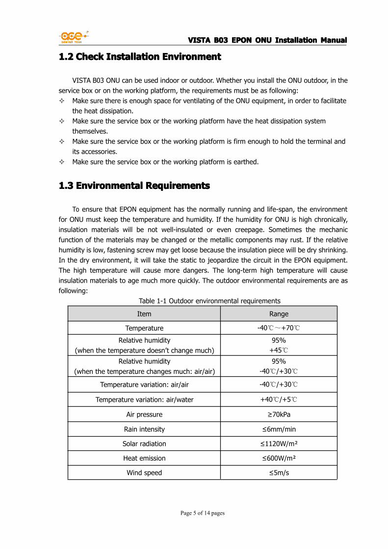
To ensure that EPON equipment has the normally running and life-span, the environmentfor ONU must keep the temperature and humidity. If the humidity for ONU is high chronically,insulation materials will be not well-insulated or even creepage. Sometimes the mechanicfunction of the materials may be changed or the metallic components may rust. If the relativehumidity is low, fastening screw may get loose because the insulation piece will be dry shrinking.In the dry environment, it will take the static to jeopardize the circuit in the EPON equipment.The high temperature will cause more dangers. The long-term high temperature will causeinsulation materials to age much more quickly. The outdoor environmental requirements are asfollowing:
Table 1-1 Outdoor environmental requirements
Item Range
Temperature -40℃~+70℃
Relative humidity(when the temperature doesn’t change much)
95%+45℃
Relative humidity(when the temperature changes much: air/air)
95%-40℃/+30℃
Temperature variation: air/air -40℃/+30℃
Temperature variation: air/water +40℃/+5℃
Air pressure ≥70kPa
Rain intensity ≤6mm/min
Solar radiation ≤1120W/m²
Heat emission ≤600W/m²
Wind speed ≤5m/s

VISTAVISTAVISTAVISTA B03B03B03B03 EPONEPONEPONEPON ONUONUONUONU InstallationInstallationInstallationInstallation ManualManualManualManual
Page 6 of 14 pages
1.3.11.3.11.3.11.3.1 CleannessCleannessCleannessCleanness RequirementsRequirementsRequirementsRequirements
Dust is a danger for safe-running of the EPON equipment. When dust falls on the equipment,it will take the static, which will lead to the poor contact of metallic connector or metallic junction.Especially when the humidity is relatively low, the static is easier to be taken. It will not onlyaffect the life-span of the equipment, but also will cause the malfunction of the communication.Besides the dust, requirements for the salt, acid, sulfide in the equipment room are demanding.These Noxious gases will fasten the erosion of the metal and the aging of some components.ONU should be put in clean environment.
1.3.21.3.21.3.21.3.2 RequirementsRequirementsRequirementsRequirements forforforfor anti-disturbanceanti-disturbanceanti-disturbanceanti-disturbance
ONU may be disturbed from outside. These disturbances will affect the equipment bycapacitance coupling, inductance coupling, electromagnetic radiation, common impedancecoupling (including grounding system) and transmission modes of the cables (etc. power cable,signal cable). So the following must be paid attention to:� AC power system is the TN system. AC power socket must be the single-phase three-cable
power socket with protection earthing(PE), to make sure the filtering circuit will filter thedisturbance of the electric network very well.
� Work location of ONU equipment should be far from super power radio-transmitting station,radar-transmitting station and high-frequency high-current equipment.
� Electromagnetic shielding should be adopted if necessary. For example, interface cablemust be electromagnetic shielding cable.
� Interface cables must be routing indoor. Outdoor routing should as covert as possible. Thisis to avoid that the overvoltage and overcurrent of lighting will damage the signal interfaceof the equipment.
1.3.31.3.31.3.31.3.3 SafetySafetySafetySafety forforforfor usingusingusingusing laserlaserlaserlaser
VISTA B03 series EPON equipment belongs to Type-1 laser equipment. If the light board ofthe VISTA B03 series EPON equipment is still running, please don’t see these light interfacesdirectly. The light bundles from the optical fibers contain high power, so they may harm theretina.
1.41.41.41.4 ToolsToolsToolsTools
� Straight screwdriver� Cross screwdriver
VISTAVISTAVISTAVISTA B03B03B03B03 EPONEPONEPONEPON ONUONUONUONU InstallationInstallationInstallationInstallation ManualManualManualManual
Page 7 of 14 pages
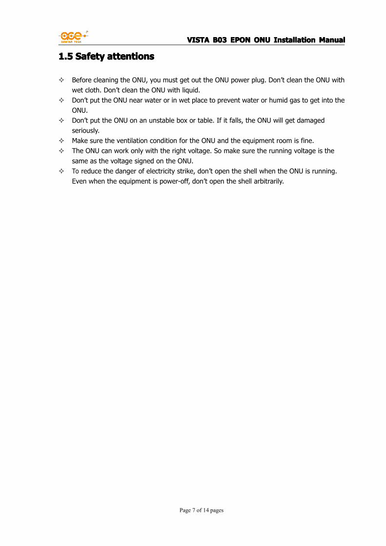
1.51.51.51.5 SafetySafetySafetySafety attentionsattentionsattentionsattentions
� Before cleaning the ONU, you must get out the ONU power plug. Don’t clean the ONU withwet cloth. Don’t clean the ONU with liquid.
� Don’t put the ONU near water or in wet place to prevent water or humid gas to get into theONU.
� Don’t put the ONU on an unstable box or table. If it falls, the ONU will get damagedseriously.
� Make sure the ventilation condition for the ONU and the equipment room is fine.� The ONU can work only with the right voltage. So make sure the running voltage is the
same as the voltage signed on the ONU.� To reduce the danger of electricity strike, don’t open the shell when the ONU is running.
Even when the equipment is power-off, don’t open the shell arbitrarily.
VISTAVISTAVISTAVISTA B03B03B03B03 EPONEPONEPONEPON ONUONUONUONU InstallationInstallationInstallationInstallation ManualManualManualManual
Page 8 of 14 pages
ChapterChapterChapterChapter 2222 InstallationInstallationInstallationInstallation
2.12.12.12.1 PreparationPreparationPreparationPreparation confirmationconfirmationconfirmationconfirmation
� Make sure you have read the contents in Chapter 1 carefully.� The requirements in Chapter One are satisfied.
2.22.22.22.2 EquipmentEquipmentEquipmentEquipment earthingearthingearthingearthing andandandand powerpowerpowerpower cablecablecablecable installationinstallationinstallationinstallation
2.2.12.2.12.2.12.2.1 EquipmentEquipmentEquipmentEquipment earthingearthingearthingearthing
Right earthing of ONU is the guarantee for anti-lighting and anti-disturbance. So customers mustcheck whether ONU and the installation environment connect the ground cable correctly.Step 1: Check whether the ONU equipment and service box have been connected to the ground.Step 2: Check whether the service box and installation environment have been connected to the
ground.
2.2.22.2.22.2.22.2.2 PowerPowerPowerPower cablecablecablecable installationinstallationinstallationinstallation
Power input for VISTA B03 ONU is 220V AC or -48V DC.Step 1: Plug the power cable of ONU into the power socket in the service box.Step 2: Switch on the power of the service box.
2.32.32.32.3 InterfaceInterfaceInterfaceInterface cablecablecablecable installationinstallationinstallationinstallation
2.3.12.3.12.3.12.3.1 CategoryCategoryCategoryCategory 5555 cablecablecablecable connectionconnectionconnectionconnection
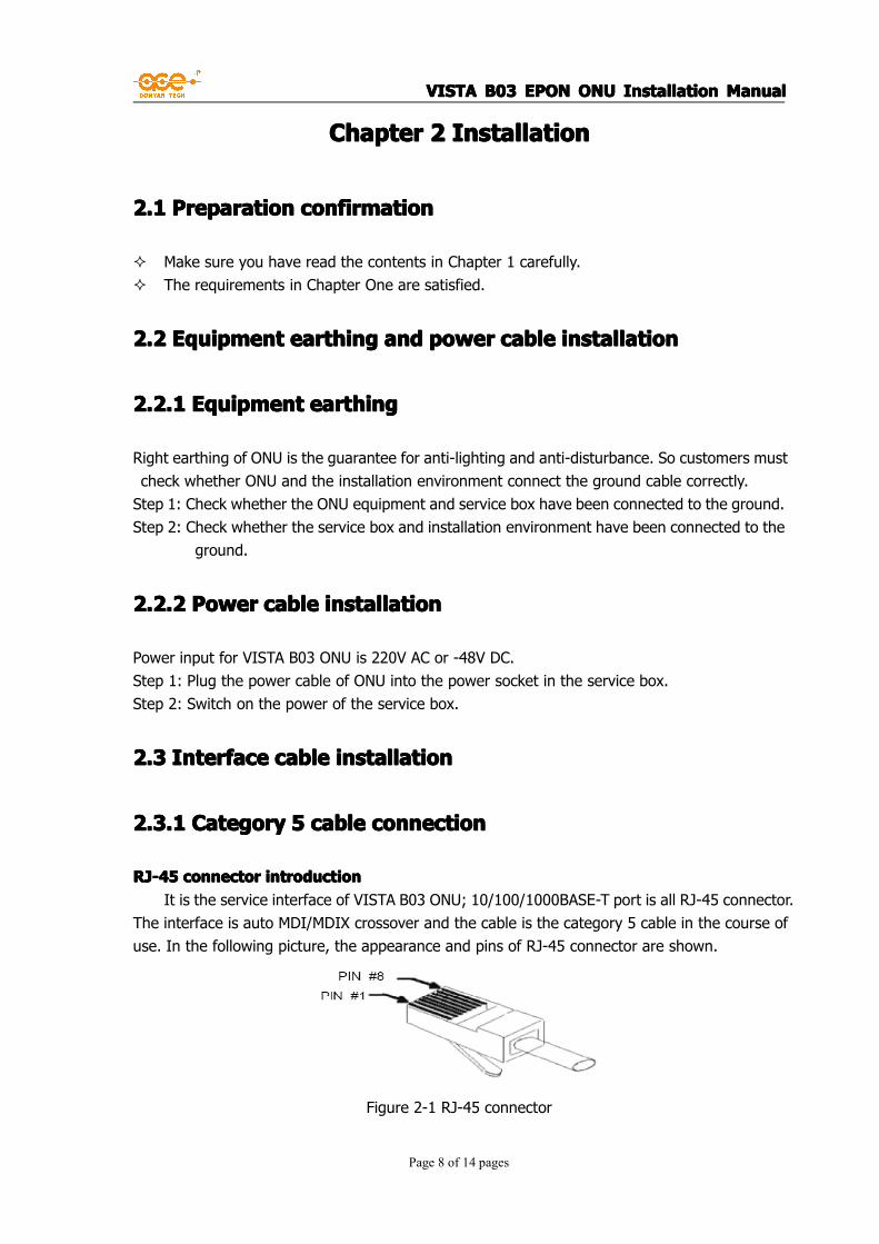
RJ-45RJ-45RJ-45RJ-45 connectorconnectorconnectorconnector introductionintroductionintroductionintroductionIt is the service interface of VISTA B03 ONU; 10/100/1000BASE-T port is all RJ-45 connector.
The interface is auto MDI/MDIX crossover and the cable is the category 5 cable in the course ofuse. In the following picture, the appearance and pins of RJ-45 connector are shown.
Figure 2-1 RJ-45 connector

VISTAVISTAVISTAVISTA B03B03B03B03 EPONEPONEPONEPON ONUONUONUONU InstallationInstallationInstallationInstallation ManualManualManualManual
Page 9 of 14 pages
Table 2-1 RJ-45 MDI port pin allocation
Pin number10/100Base-T
signal
10/100Base-T
function
1000Base-T
signal
1000Base-T
function
1 TX+ Transmitting data BIDA+Two-direction data bus
A+
2 TX- Transmitting data BIDA-Two-direction data bus
A-
3 RX+ Receiving data BIDB+Two-direction data bus
B+
4 Reserved - BIDC+Two-direction data bus
C+
5 Reserved - BIDC-Two-direction data bus
C-
6 RX- Receiving data BIDB-Two-direction data bus
B-
7 Reserved - BIDD+Two-direction data bus
D+
8 Reserved - BIDD-Two-direction data bus
D-
Table 2-2 RJ-45 MDI-X port pin allocationPin
number
10/100Base-T
signal
10/100Base-T
function
1000Base-T
signal
1000Base-T
Function
1 RX+ Receiving data BIDB+Two-direction data bus
B+
2 RX- Receiving data BIDB-Two-direction data bus
B-
3 TX+ Transmitting data BIDA+Two-direction data bus
A+
4 Reserved - BIDD+Two-direction data bus
D+
5 Reserved - BIDD-Two-direction data bus
D-
6 TX- Transmitting data BIDA-Two-direction data bus
A-
7 Reserved - BIDC+Two-direction data bus
C+
8 Reserved - BIDC-Two-direction data bus
C-
CategoryCategoryCategoryCategory 5555 CableCableCableCable connectionconnectionconnectionconnectionStep 1: Plug one end of the network cable into Ethernet connector RJ-45 which you
want to link.Step 2: Plug the other end of the network cable into Ethernet connector RJ-45 of
VISTAVISTAVISTAVISTA B03B03B03B03 EPONEPONEPONEPON ONUONUONUONU InstallationInstallationInstallationInstallation ManualManualManualManual
Page 10 of 14 pages
the other side equipment.
2.3.22.3.22.3.22.3.2 OpticalOpticalOpticalOptical fiberfiberfiberfiber installationinstallationinstallationinstallation
OpticalOpticalOpticalOptical fiberfiberfiberfiber connectorconnectorconnectorconnector introductionintroductionintroductionintroduction
When you choose the optical fiber, make sure the type of the chosen optical fiber connectoris the same as the type of the optical interface. Optical fiber connector is the indispensablepassive device in optical fiber communication system. Its usage will make possible dismountableconnection in optical channels. This will facilitate the debugging and maintenance of the opticalsystem, and make the linking more flexible. There are many types of the optical fiber connector.We only introduce SC type and LC type.
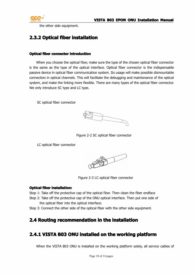
SC optical fiber connector
Figure 2-2 SC optical fiber connector
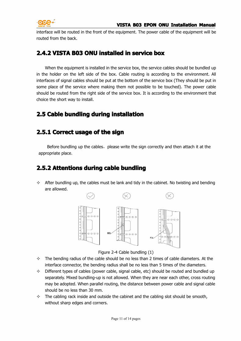
LC optical fiber connector
Figure 2-3 LC optical fiber connector
OpticalOpticalOpticalOptical fiberfiberfiberfiber installation:installation:installation:installation:Step 1: Take off the protective cap of the optical fiber. Then clean the fiber endfaceStep 2: Take off the protective cap of the ONU optical interface. Then put one side of
the optical fiber into the optical interface.Step 3: Connect the other side of the optical fiber with the other side equipment.
2.42.42.42.4 RoutingRoutingRoutingRouting recommendationrecommendationrecommendationrecommendation inininin thethethethe installationinstallationinstallationinstallation
2.4.12.4.12.4.12.4.1 VISTAVISTAVISTAVISTA B03B03B03B03 ONUONUONUONU installedinstalledinstalledinstalled onononon thethethethe workingworkingworkingworking platformplatformplatformplatform
When the VISTA B03 ONU is installed on the working platform solely, all service cables of
VISTAVISTAVISTAVISTA B03B03B03B03 EPONEPONEPONEPON ONUONUONUONU InstallationInstallationInstallationInstallation ManualManualManualManual
Page 11 of 14 pages
interface will be routed in the front of the equipment. The power cable of the equipment will berouted from the back.
2.4.22.4.22.4.22.4.2 VISTAVISTAVISTAVISTA B03B03B03B03 ONUONUONUONU installedinstalledinstalledinstalled inininin serviceserviceserviceservice boxboxboxbox
When the equipment is installed in the service box, the service cables should be bundled upin the holder on the left side of the box. Cable routing is according to the environment. Allinterfaces of signal cables should be put at the bottom of the service box (They should be put insome place of the service where making them not possible to be touched). The power cableshould be routed from the right side of the service box. It is according to the environment thatchoice the short way to install.
2.52.52.52.5 CableCableCableCable bundlingbundlingbundlingbundling duringduringduringduring installationinstallationinstallationinstallation
2.5.12.5.12.5.12.5.1 CorrectCorrectCorrectCorrect usageusageusageusage ofofofof thethethethe signsignsignsign
Before bundling up the cables,please write the sign correctly and then attach it at theappropriate place.
2.5.22.5.22.5.22.5.2 AttentionsAttentionsAttentionsAttentions duringduringduringduring cablecablecablecable bundlingbundlingbundlingbundling
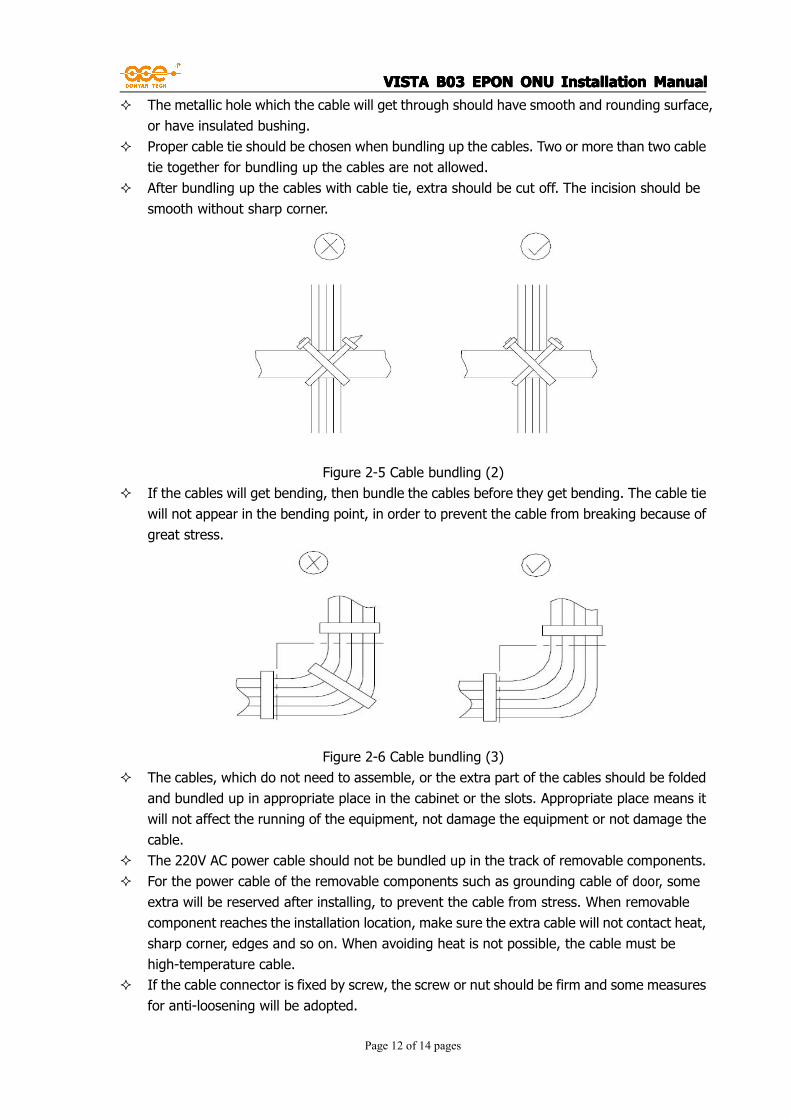
� After bundling up, the cables must be lank and tidy in the cabinet. No twisting and bendingare allowed.
Figure 2-4 Cable bundling (1)� The bending radius of the cable should be no less than 2 times of cable diameters. At the
interface connector, the bending radius shall be no less than 5 times of the diameters.� Different types of cables (power cable, signal cable, etc) should be routed and bundled up
separately. Mixed bundling-up is not allowed. When they are near each other, cross routingmay be adopted. When parallel routing, the distance between power cable and signal cableshould be no less than 30 mm.
� The cabling rack inside and outside the cabinet and the cabling slot should be smooth,without sharp edges and corners.
VISTAVISTAVISTAVISTA B03B03B03B03 EPONEPONEPONEPON ONUONUONUONU InstallationInstallationInstallationInstallation ManualManualManualManual
Page 12 of 14 pages
� The metallic hole which the cable will get through should have smooth and rounding surface,or have insulated bushing.
� Proper cable tie should be chosen when bundling up the cables. Two or more than two cabletie together for bundling up the cables are not allowed.
� After bundling up the cables with cable tie, extra should be cut off. The incision should besmooth without sharp corner.
Figure 2-5 Cable bundling (2)� If the cables will get bending, then bundle the cables before they get bending. The cable tie
will not appear in the bending point, in order to prevent the cable from breaking because ofgreat stress.
Figure 2-6 Cable bundling (3)� The cables, which do not need to assemble, or the extra part of the cables should be folded
and bundled up in appropriate place in the cabinet or the slots. Appropriate place means itwill not affect the running of the equipment, not damage the equipment or not damage thecable.
� The 220V AC power cable should not be bundled up in the track of removable components.� For the power cable of the removable components such as grounding cable of door, some
extra will be reserved after installing, to prevent the cable from stress. When removablecomponent reaches the installation location, make sure the extra cable will not contact heat,sharp corner, edges and so on. When avoiding heat is not possible, the cable must behigh-temperature cable.
� If the cable connector is fixed by screw, the screw or nut should be firm and some measuresfor anti-loosening will be adopted.

VISTAVISTAVISTAVISTA B03B03B03B03 EPONEPONEPONEPON ONUONUONUONU InstallationInstallationInstallationInstallation ManualManualManualManual
Page 13 of 14 pages
� For some hard power cable, the cable should be fixed near the end point, to prevent thestress near the end point.
� Please don’t use screw which made by yourself to fix the end point.� Power cable with the same type and the same routing direction should be bundled up
together. Then cables in the cable bundle should be clean and lank.� No knotting are allowed when bundling up the cables or routing.� For the cold-pressing end point (such as air switch), the metallic part of the old-pressing
end point should not be exposed outside when assembling.
2.62.62.62.6 CheckingCheckingCheckingChecking afterafterafterafter installationinstallationinstallationinstallation
When checking whether the installation is correct, please make sure the power supply is off,to prevent the damage of human body and the equipment. After installation, please checkaccording to the items in the following table. The listed items must work normally.
Table2-3 Table for checking after installation
Check item Normal Abnormal Remarks
Console cable - -
Ground cable - -
Power cable - -
2.72.72.72.7 Power-onPower-onPower-onPower-on
2.7.12.7.12.7.12.7.1 RecheckingRecheckingRecheckingRechecking beforebeforebeforebefore power-onpower-onpower-onpower-on
� Check whether the equipment is installed firmly.� Check whether all service cables, optical fibers, power cables and grounding cables are
installed correctly.� Check whether the voltage of power supply is the same with the requirement of the
equipment.
2.7.22.7.22.7.22.7.2 Power-onPower-onPower-onPower-on
� Plug power cable of the equipment and switch the power-supply on.

VISTAVISTAVISTAVISTA B03B03B03B03 EPONEPONEPONEPON ONUONUONUONU InstallationInstallationInstallationInstallation ManualManualManualManual
Page 14 of 14 pages
2.7.32.7.32.7.32.7.3 EquipmentEquipmentEquipmentEquipment runningrunningrunningrunning checkingcheckingcheckingchecking
Check whether the instruction lights in the front panel of the system run normally.
Table 2-4 Table for PU202 instruction lights statusLED Description
System status POWER The light will be always on (red) if the power works normally.
PON status
OPT: the
instruction light for
physical layer
optical link
The light is always on (green), which means the connection
of physical layer optical link is successful.
The light is flashing (green), which means the physical layer
optical link causes an alarm.
SER: the
instruction light for
ONU logging in the
data layer
The light is always on (green), which means the ONU logging
in the layer-2 is successful.
The light is flashing (green), which means the ONU logging in
the layer-2 is not successful.
Port status X1、X2
When 10/100/1000BASE-T interface are connected and are
working in 1000BASE-T mode, the “X1” light is always on and
flashing when data is transferred.
When 10/100/1000BASE-T interface are connected and are
working in 10/100BASE-T mode, the “X1” light is always on
and flashing when data is transferred.
When 10/100BASE-T interface are connected and are
working, the “X2” light is always on and flashing when data is
transferred.
Table 2-5 Table for PU204 instruction lights statusLED Description
System status POWER The light will be always on (red) if the power works normally.
PON Status
OPT: the
instruction light for
physical layer
optical link
The light is always on (green), which means the connection
of physical layer optical link is successful.
The light is flashing (green), which means the physical layer
optical link alarm.
SER: the
instruction light for
ONU logging in the
data layer
The light is always on (green), which means the ONU logging
in the layer-2 is successful.
The light is flashing (green), which means the ONU logging in
the layer-2 is not successful.
Port StatusX1、X2、
X3、X4
When 10/100BASE-T interface are connected and are
working, all the lights from X1 to X4 are always on and
flashing when data is transferred.


![[Presentation] GPON vs EPON](https://static.fdocuments.net/doc/165x107/552a63b555034698428b4604/presentation-gpon-vs-epon.jpg)