Vista and 1/Vista Series Non-Blending Suction Pumps … 1997 Part No. 917446 Rev L Vista and 1/Vista...
52
Vista and 1/Vista Series Non-Blending Suction Pumps and Remote Dispensers INSTALLATION
Transcript of Vista and 1/Vista Series Non-Blending Suction Pumps … 1997 Part No. 917446 Rev L Vista and 1/Vista...
Vista and 1/Vista Series Non-Blending Suction Pumps and Remote Dispensers
INST
AL
LA
TIO
N
READ THIS MANUAL BEFORE YOU BEGIN
Dispensers have both electricity and a hazardous, flammable and potentially explosive liquid. Failure to follow the below precautions and the Warning and Caution instructions in this manual may result in serious injury. Follow all rules, codes and laws that apply to your area and installation.
SAFETY PRECAUTIONS - INSTALLATION AND MAINTENANCE
Always make sure ALL power to the dispenser is turned OFF before you open the dispenser cabinet for maintenance. Physically lock, restrict access to, or tag the circuit breakers you turn off when servicing the dispenser. Be sure to trip (close) the emergency valve(s) under the dispenser BEFORE beginning mainte-nance.
Make sure that you know how to turn OFF power to the dispenser and submersible pumps in an emer-gency. Have all leaks or defects repaired immediately.
EQUIPMENT PRECAUTIONS
Be sure to bleed all air from product lines of remote dispensers and prime suction pumps before dispensing product, otherwise, damage to the equipment may occur. Always use the approved method for lifting the dispenser. Never lift by the nozzle boot, sheet metal, valance, etc., otherwise equipment damage or personal injury may occur.
HOW TO CONTACT WAYNE
Trouble with the installation and operation of the dispenser should be referred to your authorized Wayne service personnel or Wayne Technical Support (1-800-926-3737).
INDICATORS AND NOTATIONS
Danger indicates a hazard or unsafe practice which, if not avoided, will result in severe injury or possibly death.
Warning indicates a hazard or unsafe practice which, if not avoided, may result in severe injury or possibly death.
Caution indicates a hazard or unsafe practice which, if not avoided, may result in minor injury.
Note:
Important information to consider, otherwise, improper installation and/or damage to components may occur.
WARNING!
DANGER!
WARNING!
CAUTION!

October 1997 Part No. 917446 Rev L
Vista and 1/Vista Series Non-Blending Suction Pumps
and Remote DispensersInstallation Manual
Part No. 917446 Rev L October 1997
V399 V387/V388 V490
V390
V390/U V389 V490/U
TotalGallons
$
TotalGallons
$TotalGallons
$
TotalGallons
$
TotalGallons
$TotalGallons
$ TotalGallons
$
iii
October 1997 Part No. 917446 Rev L
TABLE OF CONTENTS
Title Page
1. INTRODUCTION . . . . . . . . . . . . . . . . . . . . . . . . . . . . . . . . . . . . . . . . . . . . . . . . . . . . . . . . . . . . . . . . . 1
1.1. Dispensers Covered . . . . . . . . . . . . . . . . . . . . . . . . . . . . . . . . . . . . . . . . . . . . . . . . . . . . . . . . 11.2. Safety Precautions . . . . . . . . . . . . . . . . . . . . . . . . . . . . . . . . . . . . . . . . . . . . . . . . . . . . . . . . . 21.3. Local, State and Federal Codes . . . . . . . . . . . . . . . . . . . . . . . . . . . . . . . . . . . . . . . . . . . . . . . 2
2. INSTALLATION. . . . . . . . . . . . . . . . . . . . . . . . . . . . . . . . . . . . . . . . . . . . . . . . . . . . . . . . . . . . . . . . . . 3
2.1. Equipment Inspection . . . . . . . . . . . . . . . . . . . . . . . . . . . . . . . . . . . . . . . . . . . . . . . . . . . . . . 32.2. Lifting, Anchoring and Piping . . . . . . . . . . . . . . . . . . . . . . . . . . . . . . . . . . . . . . . . . . . . . . . . 32.3. Dispenser Electrical Wiring. . . . . . . . . . . . . . . . . . . . . . . . . . . . . . . . . . . . . . . . . . . . . . . . . . 52.4. Dispenser Hydraulics. . . . . . . . . . . . . . . . . . . . . . . . . . . . . . . . . . . . . . . . . . . . . . . . . . . . . . . 6
2.4.1. Meters . . . . . . . . . . . . . . . . . . . . . . . . . . . . . . . . . . . . . . . . . . . . . . . . . . . . . . . . . . 62.4.2. Hoses/Nozzles . . . . . . . . . . . . . . . . . . . . . . . . . . . . . . . . . . . . . . . . . . . . . . . . . . . . 62.4.3. Filters. . . . . . . . . . . . . . . . . . . . . . . . . . . . . . . . . . . . . . . . . . . . . . . . . . . . . . . . . . . 6
2.5. Suction Pumps . . . . . . . . . . . . . . . . . . . . . . . . . . . . . . . . . . . . . . . . . . . . . . . . . . . . . . . . . . . . 72.5.1. Check Valves. . . . . . . . . . . . . . . . . . . . . . . . . . . . . . . . . . . . . . . . . . . . . . . . . . . . . 72.5.2. Connecting More Than One Pump To A Tank . . . . . . . . . . . . . . . . . . . . . . . . . . . 72.5.3. V-Link Belt . . . . . . . . . . . . . . . . . . . . . . . . . . . . . . . . . . . . . . . . . . . . . . . . . . . . . . 72.5.4. Vapor Recovery. . . . . . . . . . . . . . . . . . . . . . . . . . . . . . . . . . . . . . . . . . . . . . . . . . . 7
3. ENGINEERING DRAWINGS . . . . . . . . . . . . . . . . . . . . . . . . . . . . . . . . . . . . . . . . . . . . . . . . . . . . . . . 9
4. DISPENSER INTERCONNECTION WIRING DIAGRAMS . . . . . . . . . . . . . . . . . . . . . . . . . . . . . . 39
LIST OF FIGURES
Figure 2-1. Typical Emergency Valve Installation . . . . . . . . . . . . . . . . . . . . . . . . . . . . . . . . . . . . . . . . 4Figure 3-1. 10205-B Vista Field Lifting Instructions. . . . . . . . . . . . . . . . . . . . . . . . . . . . . . . . . . . . . 10Figure 3-2. 7115-C Valance Installation Instructions . . . . . . . . . . . . . . . . . . . . . . . . . . . . . . . . . . . . 11Figure 3-3. 6595-D Lighted Valance Installation Instructions. . . . . . . . . . . . . . . . . . . . . . . . . . . . . . 12
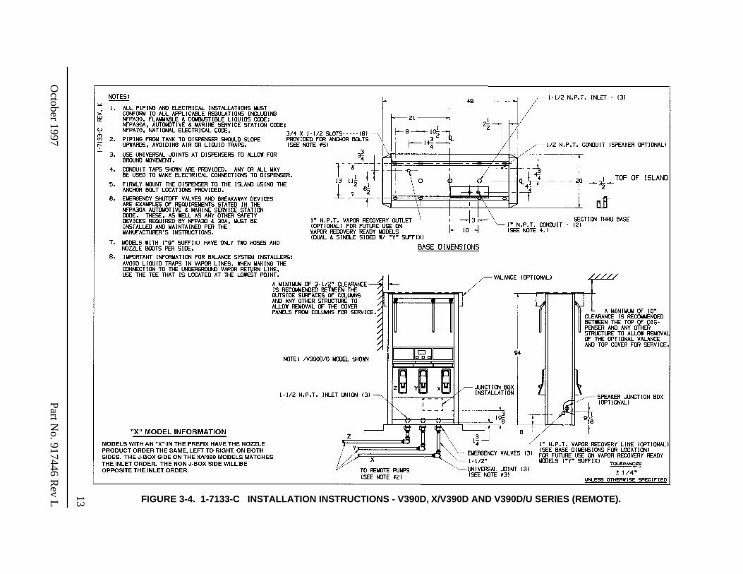
Figure 3-4. 1-7133-C Installation Instructions - V390D, X/V390D and V390D/U Series
(Remote)
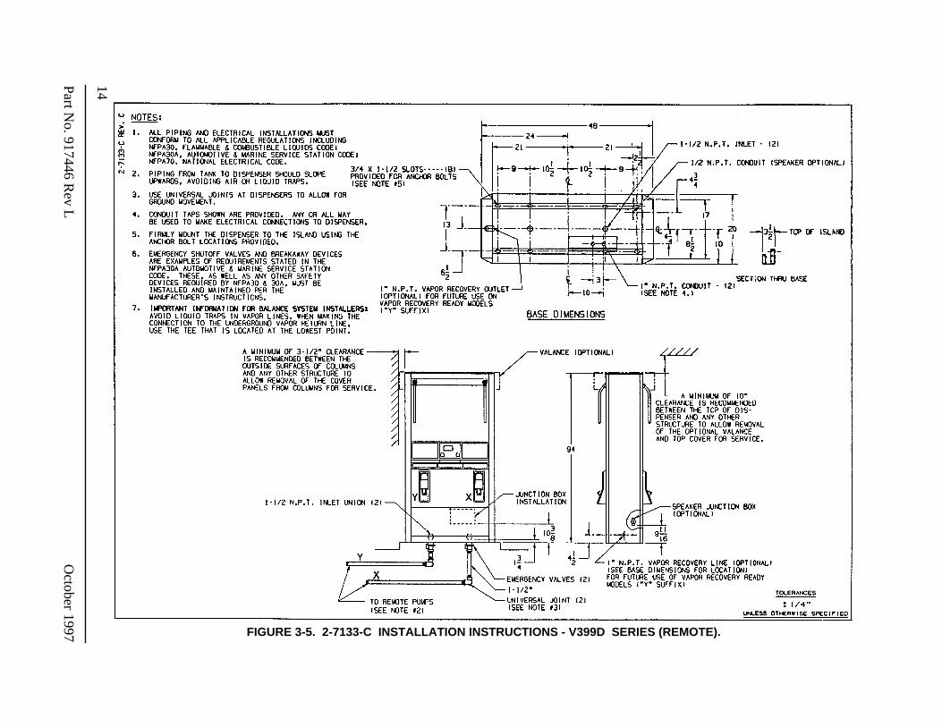
. 13Figure 3-5. 2-7133-C Installation Instructions - V399D Series
(Remote)
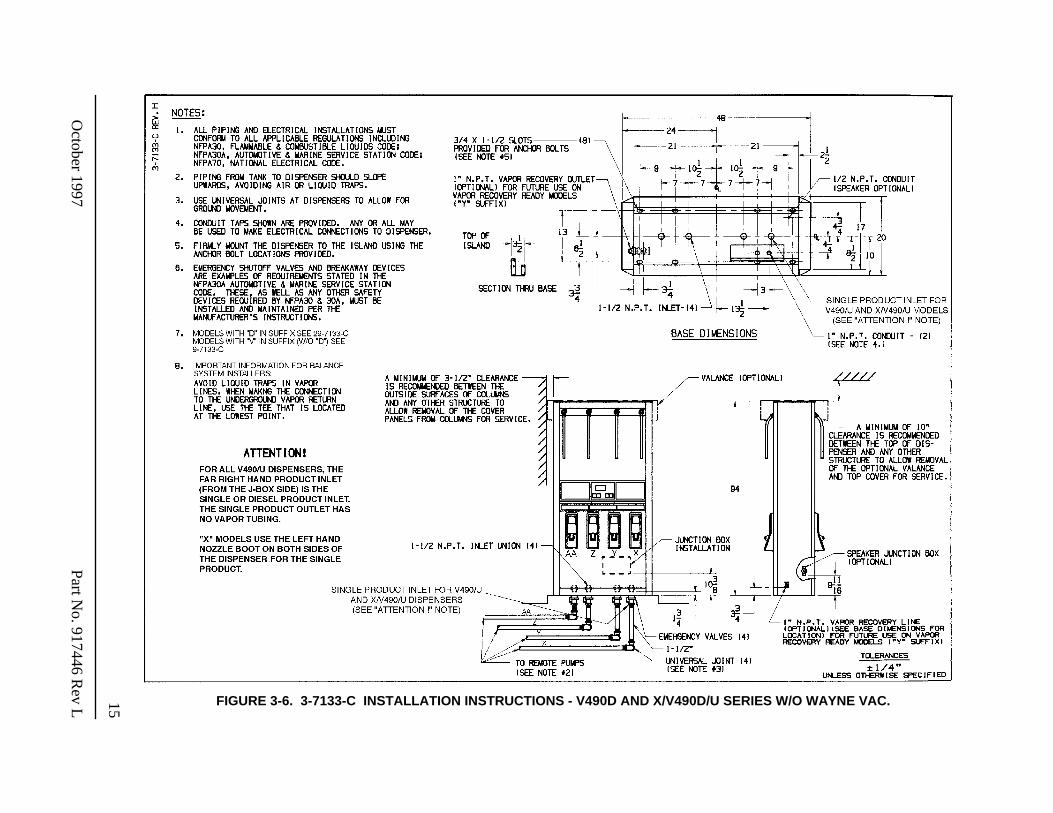
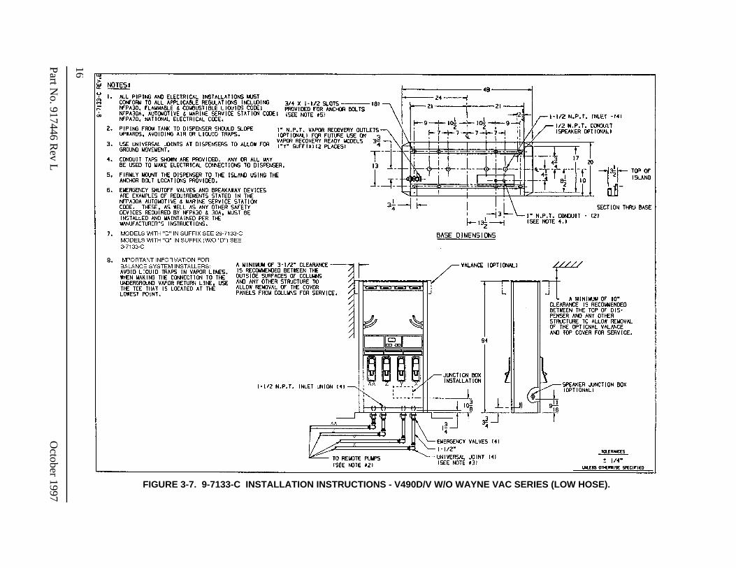
. . . . . . . . . . . . . . . . . . . . . 14Figure 3-6. 3-7133-C Installation Instructions - V490D and X/V490D/U Series w/o Wayne Vac. . 15Figure 3-7. 9-7133-C Installation Instructions - V490D/V w/o Wayne Vac Series (Low Hose) . . . 16
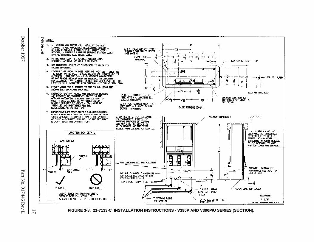
Figure 3-8. 21-7133-C Installation Instructions - V390P and V390P/U Series
(Suction)
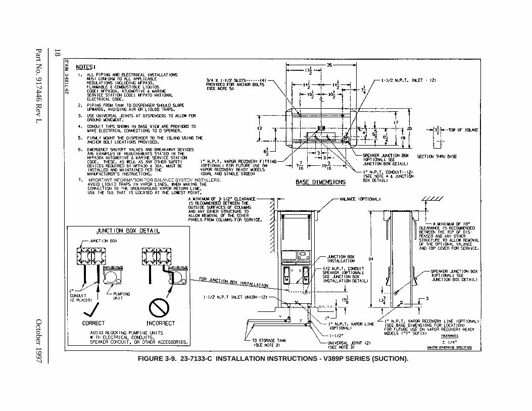
. . . . . . . . . 17Figure 3-9. 23-7133-C Installation Instructions - V389P Series
(Suction)
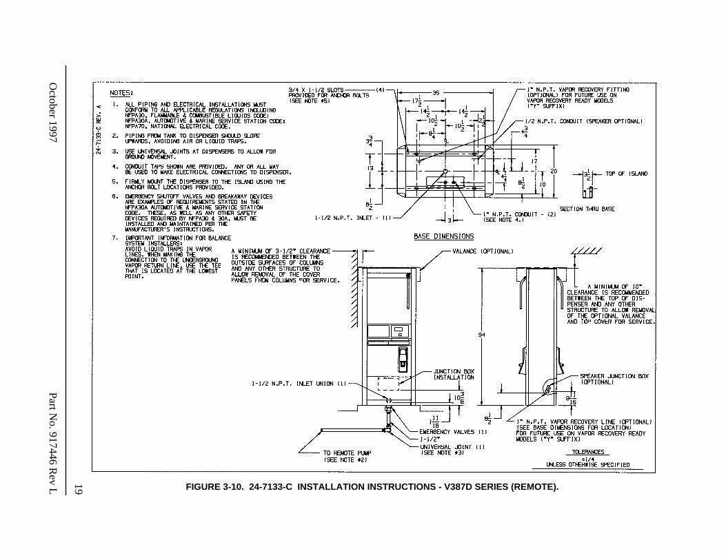
. . . . . . . . . . . . . . . . . . . . . 18Figure 3-10. 24-7133-C Installation Instructions - V387D Series
(Remote)
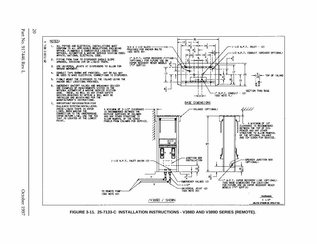
. . . . . . . . . . . . . . . . . . . . 19Figure 3-11. 25-7133-C Installation Instructions - V388D and V389D Series
(Remote)
. . . . . . . . . . . 20
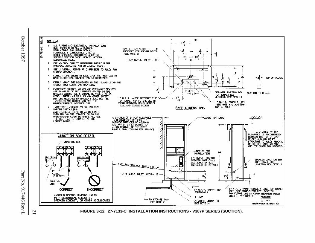
Figure 3-12. 27-7133-C Installation Instructions - V387P Series
(Suction)
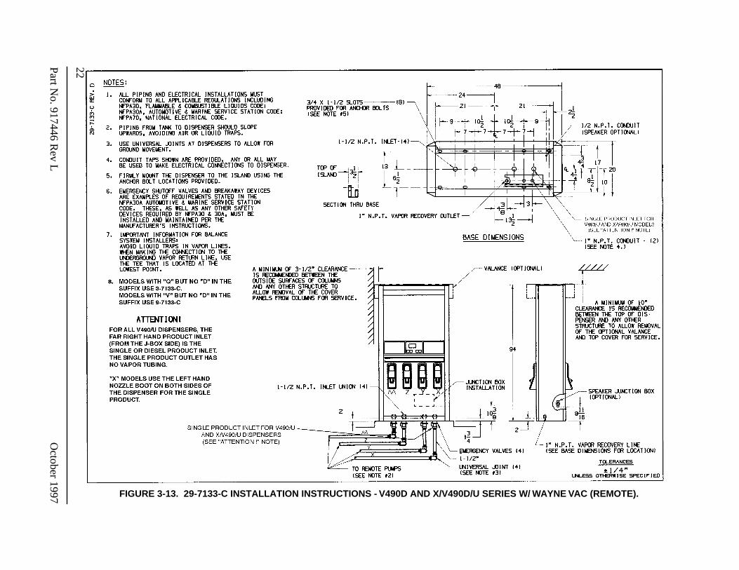
. . . . . . . . . . . . . . . . . . . . . 21Figure 3-13. 29-7133-C Installation Instructions - V490D and X/V490D/U Series w/ Wayne Vac. . 22Figure 3-14. 30-7133-C Installation Instructions - V399P Series
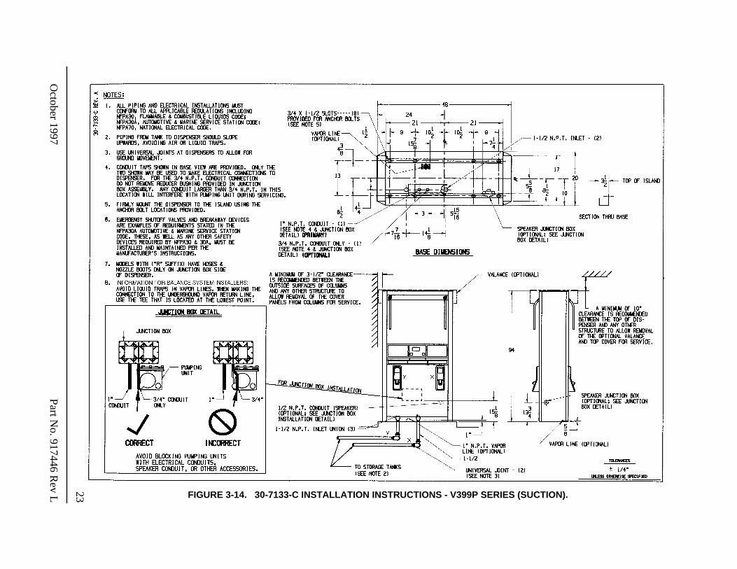
(Suction)
. . . . . . . . . . . . . . . . . . . . . 23
iv
Part No. 917446 Rev L October 1997
LIST OF FIGURES
, continued
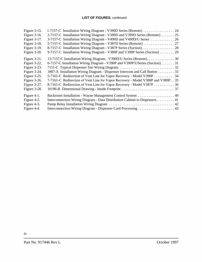
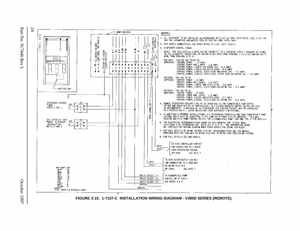
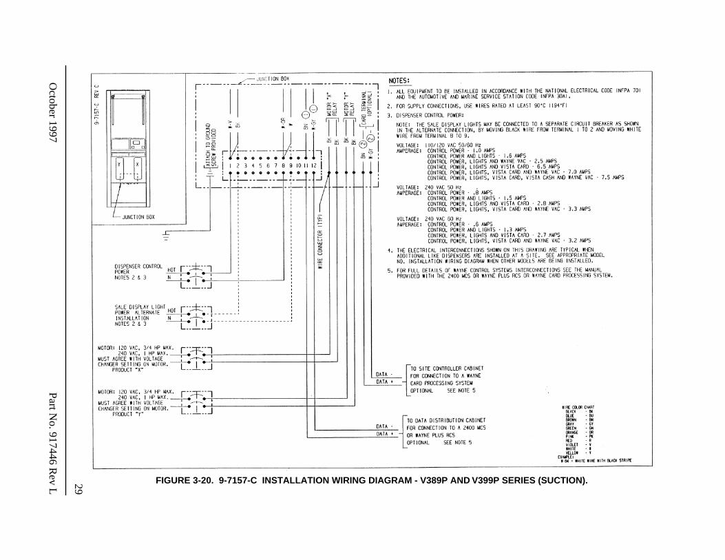
Figure 3-15. 1-7157-C Installation Wiring Diagram - V390D Series (Remote) . . . . . . . . . . . . . . . . . 24Figure 3-16. 2-7157-C Installation Wiring Diagram - V389D and V399D Series (Remote) . . . . . . . 25Figure 3-17. 3-7157-C Installation Wiring Diagram - V490D and V490D/U Series . . . . . . . . . . . . . 26Figure 3-18. 5-7157-C Installation Wiring Diagram - V387D Series (Remote) . . . . . . . . . . . . . . . . . 27Figure 3-19. 8-7157-C Installation Wiring Diagram - V387P Series (Suction). . . . . . . . . . . . . . . . . . 28Figure 3-20. 9-7157-C Installation Wiring Diagram - V389P and V399P Series (Suction) . . . . . . . . 29
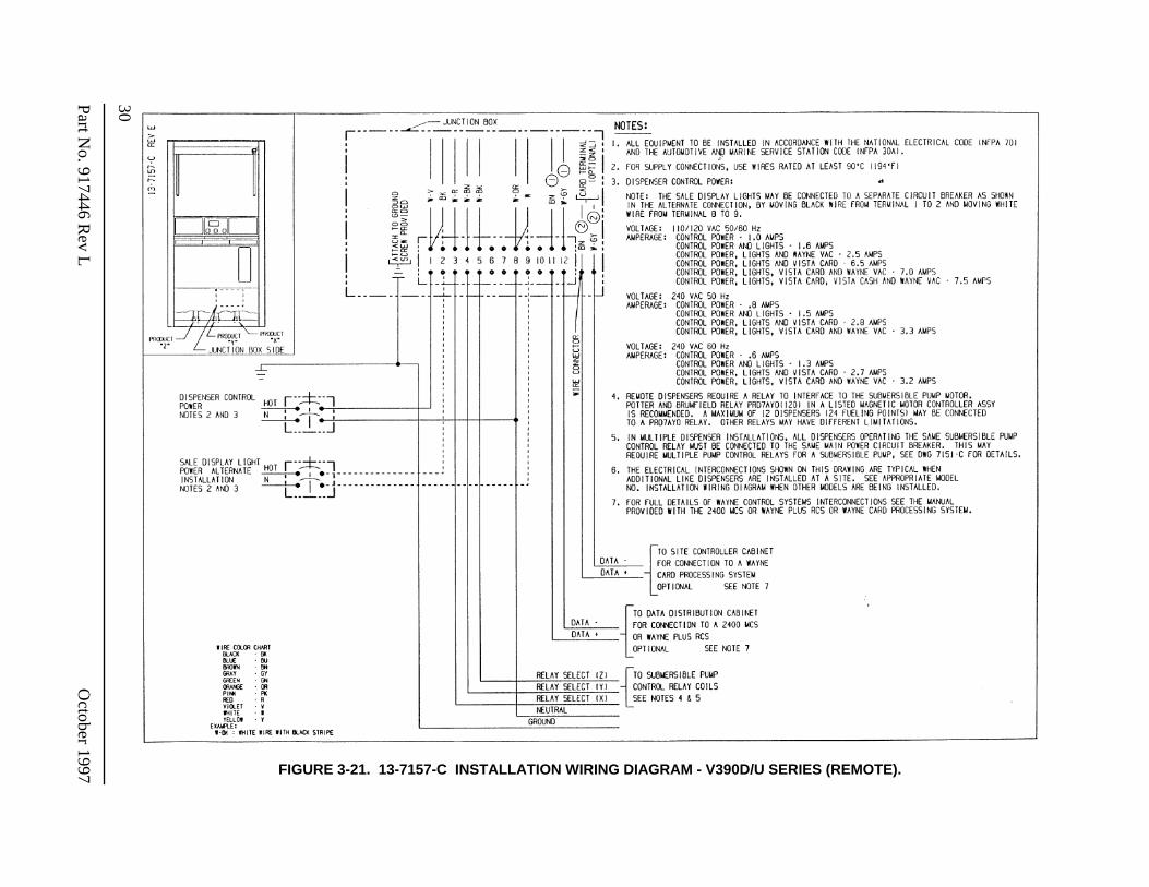
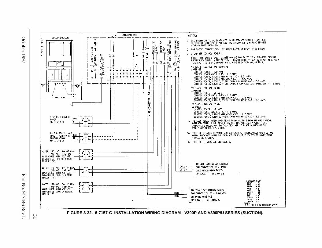
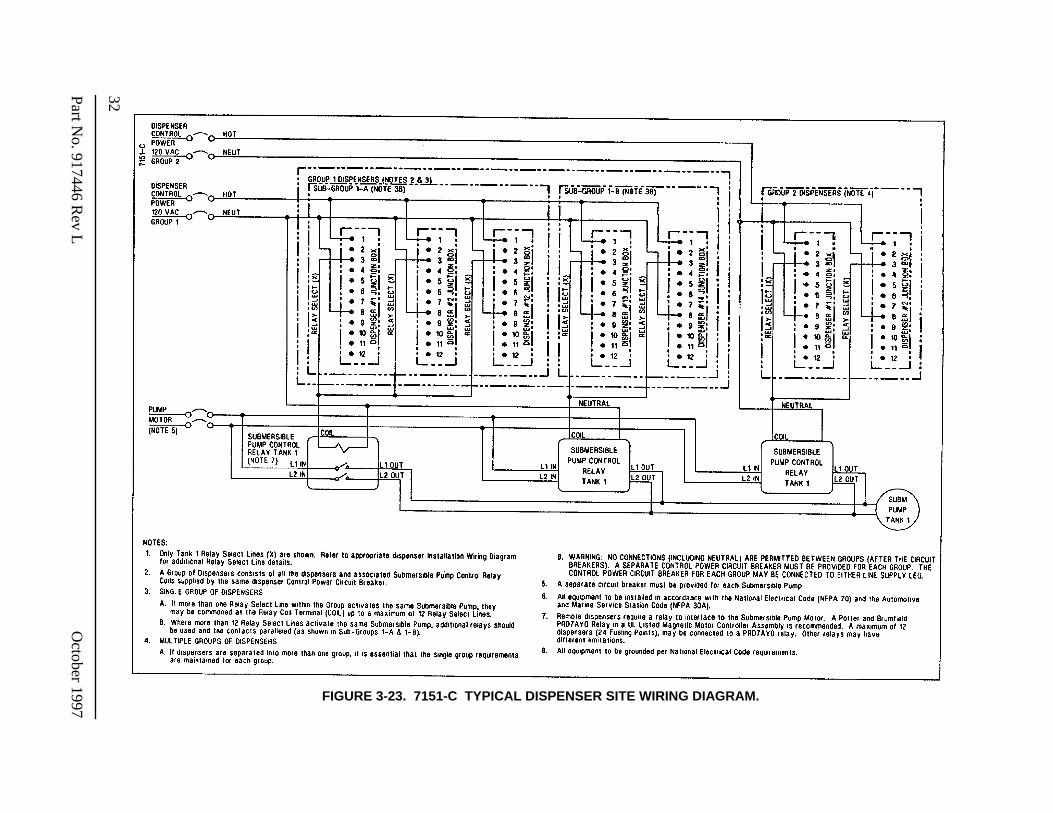
Figure 3-21. 13-7157-C Installation Wiring Diagram - V390D/U Series (Remote). . . . . . . . . . . . . . . 30Figure 3-22. 6-7157-C Installation Wiring Diagram - V390P and V390P/USeries (Suction) . . . . . . . 31Figure 3-23. 7151-C Typical Dispenser Site Wiring Diagram. . . . . . . . . . . . . . . . . . . . . . . . . . . . . . . 32Figure 3-24. 1887-A Installation Wiring Diagram - Dispenser Intercom and Call Button . . . . . . . . . 33Figure 3-25. 5-7161-C Redirection of Vent Line for Vapor Recovery - Model V390P . . . . . . . . . . . 34Figure 3-26. 7-7161-C Redirection of Vent Line for Vapor Recovery - Model V388P and V389P . . 35Figure 3-27. 8-7161-C Redirection of Vent Line for Vapor Recovery - Model V387P . . . . . . . . . . . 36Figure 3-28. 10196-B Dimensional Drawing - Inside Footprint . . . . . . . . . . . . . . . . . . . . . . . . . . . . . 37
Figure 4-1. Backroom Installation - Wayne Management Control System . . . . . . . . . . . . . . . . . . . . 40Figure 4-2. Interconnection Wiring Diagram - Data Distribution Cabinet to Dispensers. . . . . . . . . . 41Figure 4-3. Pump Relay Installation Wiring Diagram . . . . . . . . . . . . . . . . . . . . . . . . . . . . . . . . . . . . 42Figure 4-4. Interconnection Wiring Diagram - Dispenser Card Processing . . . . . . . . . . . . . . . . . . . . 43
1
October 1997 Part No. 917446 Rev L
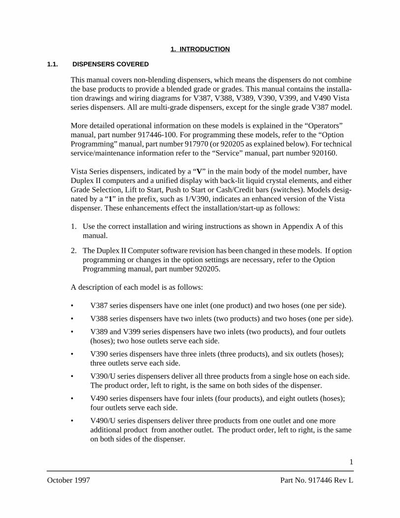
1. INTRODUCTION
1.1. DISPENSERS COVERED
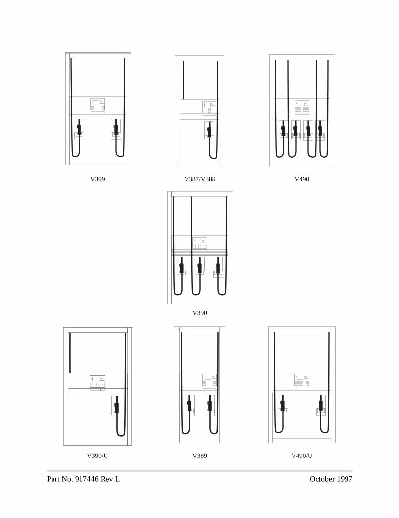
This manual covers non-blending dispensers, which means the dispensers do not combine the base products to provide a blended grade or grades. This manual contains the installa-tion drawings and wiring diagrams for V387, V388, V389, V390, V399, and V490 Vista series dispensers. All are multi-grade dispensers, except for the single grade V387 model.
More detailed operational information on these models is explained in the “Operators” manual, part number 917446-100. For programming these models, refer to the “Option Programming” manual, part number 917970 (or 920205 as explained below). For technical service/maintenance information refer to the “Service” manual, part number 920160.
Vista Series dispensers, indicated by a “
V
” in the main body of the model number, have Duplex II computers and a unified display with back-lit liquid crystal elements, and either Grade Selection, Lift to Start, Push to Start or Cash/Credit bars (switches). Models desig-nated by a “
1
” in the prefix, such as 1/V390, indicates an enhanced version of the Vista dispenser. These enhancements effect the installation/start-up as follows:
1. Use the correct installation and wiring instructions as shown in Appendix A of this manual.
2. The Duplex II Computer software revision has been changed in these models. If option programming or changes in the option settings are necessary, refer to the Option Programming manual, part number 920205.
A description of each model is as follows:
• V387 series dispensers have one inlet (one product) and two hoses (one per side).
• V388 series dispensers have two inlets (two products) and two hoses (one per side).
• V389 and V399 series dispensers have two inlets (two products), and four outlets (hoses); two hose outlets serve each side.
• V390 series dispensers have three inlets (three products), and six outlets (hoses); three outlets serve each side.
• V390/U series dispensers deliver all three products from a single hose on each side. The product order, left to right, is the same on both sides of the dispenser.
• V490 series dispensers have four inlets (four products), and eight outlets (hoses); four outlets serve each side.
• V490/U series dispensers deliver three products from one outlet and one more additional product from another outlet. The product order, left to right, is the same on both sides of the dispenser.
2
Part No. 917446 Rev L October 1997
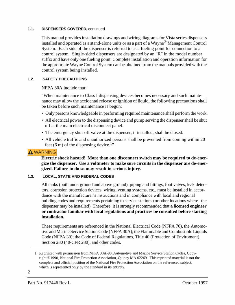
1.1. DISPENSERS COVERED,
continued
This manual provides installation drawings and wiring diagrams for Vista series dispensers installed and operated as a stand-alone units or as a part of a Wayne
®
Management Control System. Each side of the dispenser is referred to as a fueling point for connection to a control system. Single-sided dispensers are designated by an “R” in the model number suffix and have only one fueling point. Complete installation and operation information for the appropriate Wayne Control System can be obtained from the manuals provided with the control system being installed.
1.2. SAFETY PRECAUTIONS
NFPA 30A include that:
“When maintenance to Class I dispensing devices becomes necessary and such mainte-nance may allow the accidental release or ignition of liquid, the following precautions shall be taken before such maintenance is begun:
• Only persons knowledgeable in performing required maintenance shall perform the work.
• All electrical power to the dispensing device and pump serving the dispenser shall be shut off at the main electrical disconnect panel.
• The emergency shut-off valve at the dispenser, if installed, shall be closed.
• All vehicle traffic and unauthorized persons shall be prevented from coming within 20 feet (6 m) of the dispensing device.
1
”
WARNING!
Electric shock hazard! More than one disconnect switch may be required to de-ener-gize the dispenser. Use a voltmeter to make sure circuits in the dispenser are de-ener-gized. Failure to do so may result in serious injury.
1.3. LOCAL, STATE AND FEDERAL CODES
All tanks (both underground and above ground), piping and fittings, foot valves, leak detec-tors, corrosion protection devices, wiring, venting systems, etc., must be installed in accor-dance with the manufacturer’s instructions and in compliance with local and regional building codes and requirements pertaining to service stations (or other locations where the dispenser may be installed). Therefore, it is strongly recommended that
a licensed engineer or contractor familiar with local regulations and practices be consulted before starting installation.
These requirements are referenced in the National Electrical Code (NFPA 70), the Automo-tive and Marine Service Station Code (NFPA 30A); the Flammable and Combustible Liquids Code (NFPA 30); the Code of Federal Regulations, Title 40 (Protection of Enviroment), Section 280 (40-CFR 280), and other codes.
1. Reprinted with permission from NFPA 30A-90, Automotive and Marine Service Station Codes, Copy-right ©1990, National Fire Protection Association, Quincy MA 02269. This reprinted material is not the complete and official position of the National Fire Protection Association on the referenced subject, which is represented only by the standard in its entirety.
3
October 1997 Part No. 917446 Rev L
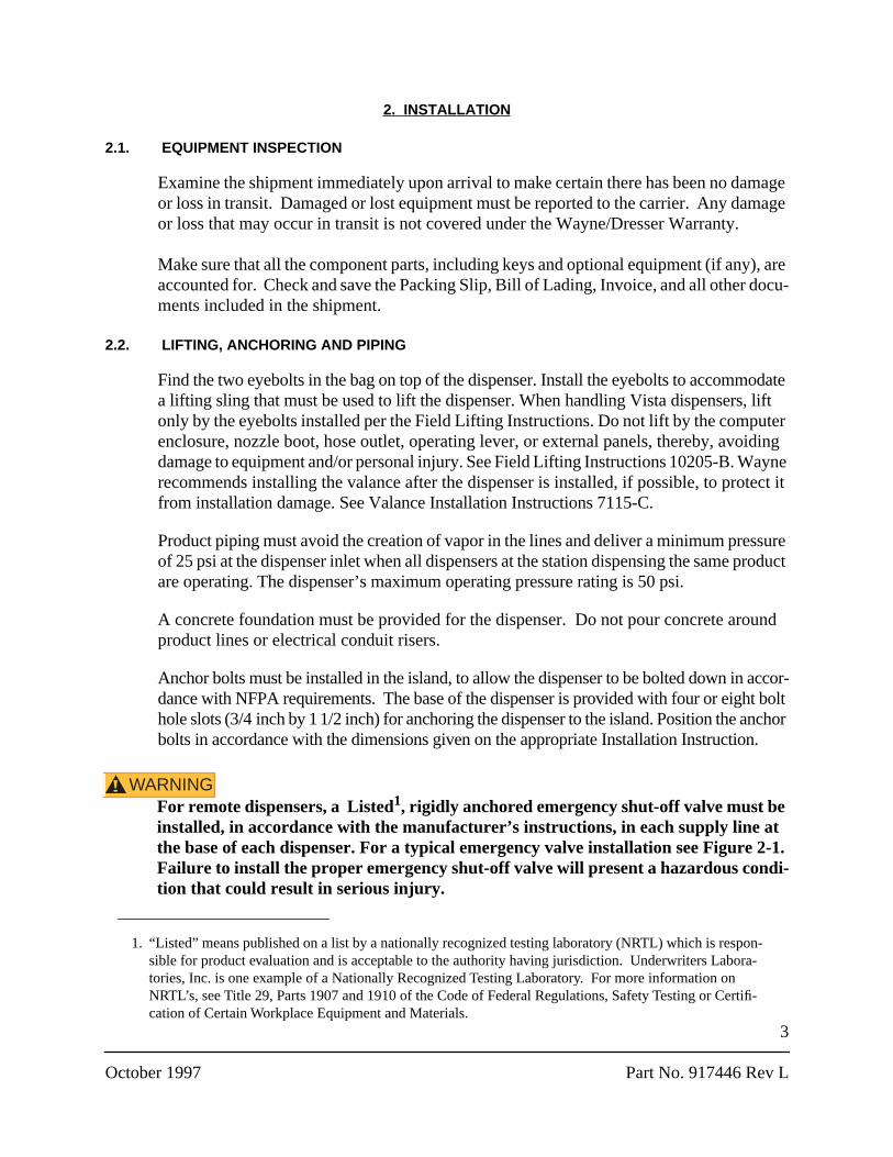
2. INSTALLATION
2.1. EQUIPMENT INSPECTION
Examine the shipment immediately upon arrival to make certain there has been no damage or loss in transit. Damaged or lost equipment must be reported to the carrier. Any damage or loss that may occur in transit is not covered under the Wayne/Dresser Warranty.
Make sure that all the component parts, including keys and optional equipment (if any), are accounted for. Check and save the Packing Slip, Bill of Lading, Invoice, and all other docu-ments included in the shipment.
2.2. LIFTING, ANCHORING AND PIPING
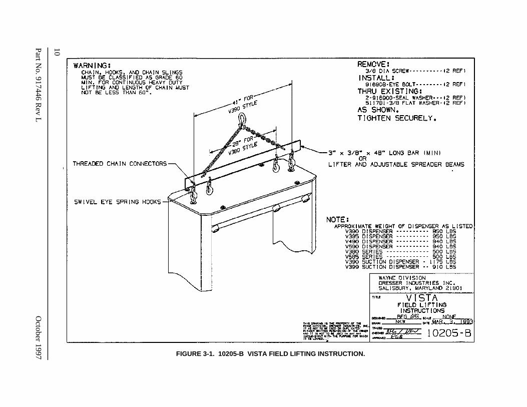
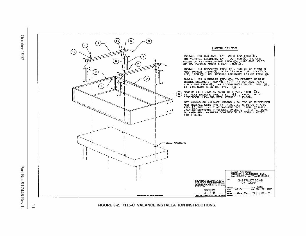
Find the two eyebolts in the bag on top of the dispenser. Install the eyebolts to accommodate a lifting sling that must be used to lift the dispenser. When handling Vista dispensers, lift only by the eyebolts installed per the Field Lifting Instructions. Do not lift by the computer enclosure, nozzle boot, hose outlet, operating lever, or external panels, thereby, avoiding damage to equipment and/or personal injury. See Field Lifting Instructions 10205-B. Wayne recommends installing the valance after the dispenser is installed, if possible, to protect it from installation damage. See Valance Installation Instructions 7115-C.
Product piping must avoid the creation of vapor in the lines and deliver a minimum pressure of 25 psi at the dispenser inlet when all dispensers at the station dispensing the same product are operating. The dispenser’s maximum operating pressure rating is 50 psi.
A concrete foundation must be provided for the dispenser. Do not pour concrete around product lines or electrical conduit risers.
Anchor bolts must be installed in the island, to allow the dispenser to be bolted down in accor-dance with NFPA requirements. The base of the dispenser is provided with four or eight bolt hole slots (3/4 inch by 1
1/2 inch) for anchoring the dispenser to the island. Position the anchor bolts in accordance with the dimensions given on the appropriate Installation Instruction.
WARNING!
For remote dispensers, a
Listed
1
, rigidly anchored emergency shut-off valve must be installed, in accordance with the manufacturer’s instructions, in each supply line at the base of each dispenser. For a typical emergency valve installation see Figure 2-1.Failure to install the proper emergency shut-off valve will present a hazardous condi-tion that could result in serious injury.
1. “Listed” means published on a list by a nationally recognized testing laboratory (NRTL) which is respon-sible for product evaluation and is acceptable to the authority having jurisdiction. Underwriters Labora-tories, Inc. is one example of a Nationally Recognized Testing Laboratory. For more information on NRTL’s, see Title 29, Parts 1907 and 1910 of the Code of Federal Regulations, Safety Testing or Certifi-cation of Certain Workplace Equipment and Materials.
4
Part No. 917446 Rev L October 1997
2.2 LIFTING, ANCHORING AND PIPING,
continued
Vertical supply risers and electrical conduits must be located per the Installation Instruction for the specific model. Proper height must be maintained to avoid undue stress on the dispenser.
Remove the shipping discs from the inlet unions before connecting the product piping. When making piping connections, wash all cutting oils off the threads and use a U.L. classified pipe joint sealing compound rated for use with petroleum-based products.
Fuel containment apparatus must be Listed
for use with Class 1, Division 1, Group D. See drawing number 10196-B for dimensional specifications for fuel containment installation.
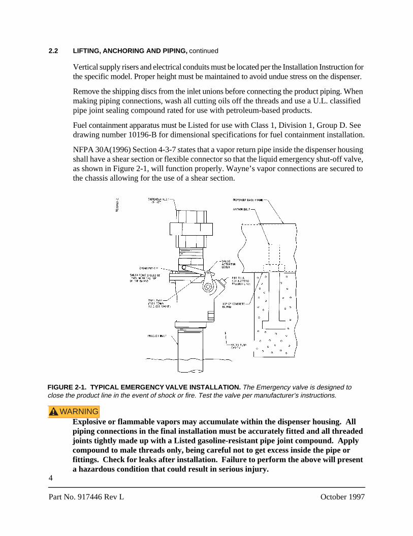
NFPA 30A(1996) Section 4-3-7 states that a vapor return pipe inside the dispenser housing shall have a shear section or flexible connector so that the liquid emergency shut-off valve, as shown in Figure 2-1, will function properly. Wayne’s vapor connections are secured to the chassis allowing for the use of a shear section.
WARNING!
Explosive or flammable vapors may accumulate within the dispenser housing. All piping connections in the final installation must be accurately fitted and all threaded joints tightly made up with a Listed gasoline-resistant pipe joint compound. Apply compound to male threads only, being careful not to get excess inside the pipe or fittings. Check for leaks after installation. Failure to perform the above will present a hazardous condition that could result in serious injury.
FIGURE 2-1. TYPICAL EMERGENCY VALVE INSTALLATION.
The Emergency valve is designed to close the product line in the event of shock or fire. Test the valve per manufacturer’s instructions.
5
October 1997 Part No. 917446 Rev L
2.3. DISPENSER ELECTRICAL WIRING
Employ a qualified licensed electrician for all wiring. All wiring must be in accordance with the National Electric Code (NFPA) and all federal, state and local regulations. Refer to the dispenser installation wiring diagrams in this manuals.
A primary requirement in dispenser installation wiring is to provide a means for discon-necting all power connections, including the neutral, to the dispensers for safe shutdown and servicing of the units. Each dispenser can be provided with a separate control Power Circuit Breaker.
If this is not desirable or practical, several dispensers can be grouped together and tied to the same Control Power Circuit Breaker as illustrated in wiring diagram 7151-C. A group of dispensers would then consist of all the dispensers and associated Submersible Pump Control Relay coils supplied by the same Control Power Circuit Breaker.
When more than one dispenser within the group activates the same submersible pump, the Relay Select lines may be tied together at the Submersible Pump Control Relay Coil terminal up to a maximum of 12 connections (24 fueling points). Where more than 12 connections activate the same submersible pump, additional relays should be used and the contacts paralleled as illustrated in 7151-C. In larger installations, dispensers can be sepa-rated into multiple groups.
WARNING!
Electric Shock Hazard! No connections (including neutral) may be shared between groups of dispensers. A separate Control Power Circuit Breaker must be provided for each group. All dispensers and electrical connection boxes must be grounded per NFPA 70. Failure to do so may result in serious injury.
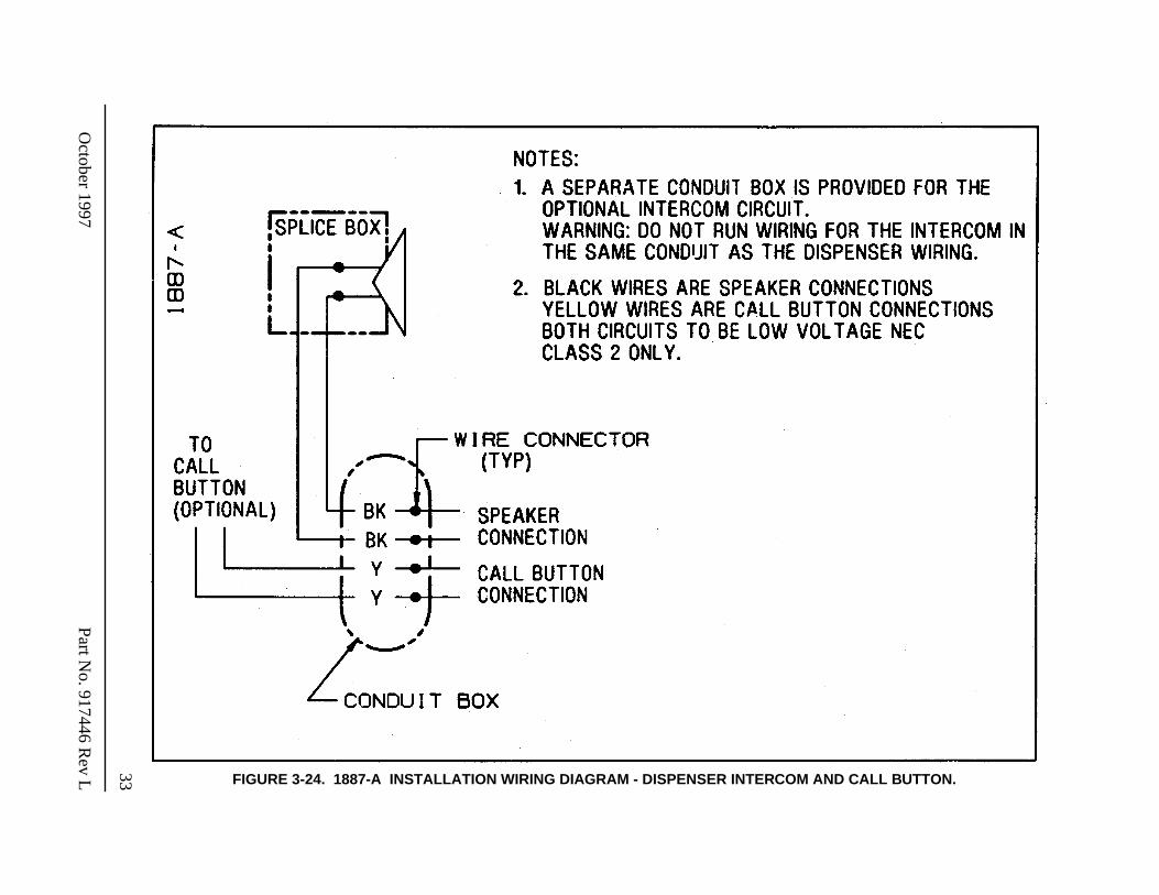
Data wires from the Wayne Control System may be installed in the same conduit containing the AC power wiring to the dispenser (NEC Class 1) if the data wires are a minimum of 18 ga, 600V, 90
°
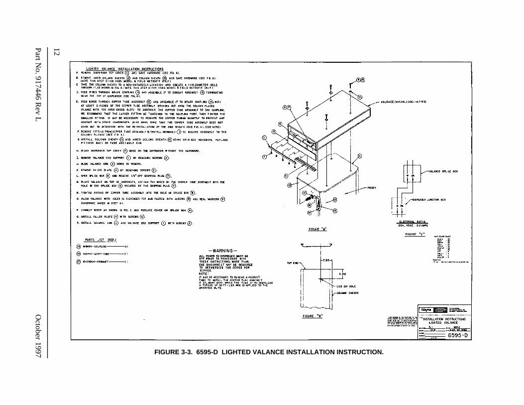
C, gas and oil resistant. Intercom/Speaker (NEC Class 2) must be installed via a separate conduit. A separate conduit box is provided for the optional intercom circuit. See wiring diagram 1887-A for wiring; black wires are speaker connec-tions; yellow wires are call button connections. Both circuits to be low voltage NEC class 2 only. Lighted valance assemblies must be Listed for installation above Class 1 Hazardous locations. Follow the instructions provided by the lighted valanced manfacturer.
If the optional DATA wires are run, they should not be physically connected to the DATA terminals in the dispenser junction box. Instead they should be properly terminated individ-ually using wire nuts.
‘Lockout/Tagout’ requirements of the U.S. Dept. of Labor, Occupational Safety and Health Administration (OSHA) may also apply. Refer to Title 29, Part 1910 of the Code of Federal Regulations (29CFR1910), Control of Hazardous Energy Source (Lockout/Tagout).
6
Part No. 917446 Rev L October 1997
2.4. DISPENSER HYDRAULICS
WARNING!
Explosive or flammable vapors may accumulate within the dispenser housing. All piping connections in the final installation must be accurately fitted and all threaded joints tightly made up with a Listed gasoline-resistant pipe joint compound. Put the compound on male threads only, being careful not to get excess inside the pipe or fittings. Failure to perform the above will present a hazardous condition that could result in serious injury.
2.4.1. Meters
All meters are adjusted for accuracy at the factory before shipping. However, depending on local jurisdiction, it may be required to check the accuracy of the meter after installation and prior to placing the dispenser in service. If the meter requires adjustment, refer to the adjustment and calibration procedures detailed in the dispenser Service manual p/n 920160.
Note: Check your local code requirements concerning meter adjustment, certification and sealing, and comply accordingly.
2.4.2. Hoses/Nozzles
Use only Listed hoses and nozzles. The nozzle guide up inside the nozzle boot must be removed on Lift-to-Start model nozzle boots to allow proper fit and function of the following nozzles: Husky 5210 and 5310; OPW 11VF47, 111V22 and 111V47; Emco Wheaton 4005.
WARNING!
Continuity must be present between the dispenser outlet and nozzle spout to prevent static discharge while fueling. Continuity must be checked for each outlet/hose assembly to insure that the nozzle is grounded. Failure to do so may result in a hazardous condition that could cause serious injury.
2.4.3. Filters
Replacement fuel filters must be UL recognized.
WARNING!
Before removing the strainer or filter turn the power to the dispenser and submersible pump(s) OFF and close the emergency shear valves on the dispenser being serviced. Failure to do so may result in fuel being spilled or sprayed - a hazardous condition that can result in serious injury. Loosen strainer cap or spin-on filter slightly and allow the fuel to drain into an appropriate container until pressure is relieved. Return the access fuel to the appropriate underground tank. Failure to prevent fuel drainage under and around the dispenser could cause a possible fire hazard that may result in serious injury.
7
October 1997 Part No. 917446 Rev L
2.5. SUCTION PUMPS
2.5.1. Check Valves
Suction pumps require a check valve in the product lines to stop product from draining back to the tank. Wayne recommends double poppet foot (extractable) valves inside the under-ground tank. The foot valves should be the same size as the suction lines.
A spring-loaded valve of any kind is not recommended. Springs increase pumping resis-tance and may cause erratic operations. The valve used should be one designed for use with petroleum products.
Install the valves per manfacturer’s installation instructions. The bottom of the suction stub must be at least four inches (4") off the bottom of the tank. Condensation is constantly going on inside the tank creating water which settles to the bottom. Checking tanks for water regularly and keeping them clean reduces the risk of drawing water and debris into the lines and dispenser.
2.5.2. Connecting More Than One Pump To A Tank
If more than one suction pump will be connected to a tank, it is best to obtain a tank with enough openings to provide each pump with a separate suction line. Tanks used in remote systems normally require only one (submersible) pump to supply several dispensers; tanks designed specifically for suction pumps will have additional openings.
If a tank with only one opening is unavoidable, it is important that a check valve be used in each suction line branch, and that each valve be placed in the line as close as possible to the connection leading to the main suction line coming from the tank. This is necessary to prevent a pump from emptying the line leading to another pump instead of pulling the product out of the tank.
2.5.3. V-Link Belt
Adjustments to the V-Link belt on suction pump models should be performed in accor-dance with the V-Link belt Installation manual, part number 920057.
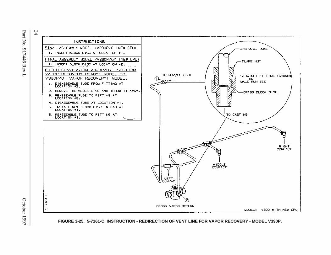
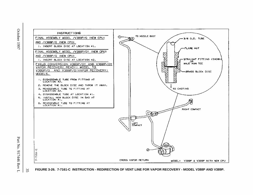
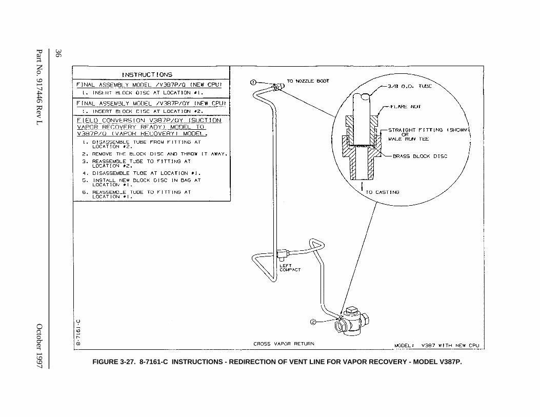
2.5.4. Vapor Recovery
See the appropriate 7161-C series Instruction drawing for the specific suction model to covert from vapor ready to vapor recovery.

8
Part No. 917446 Rev L October 1997
9
October 1997 Part No. 917446 Rev L
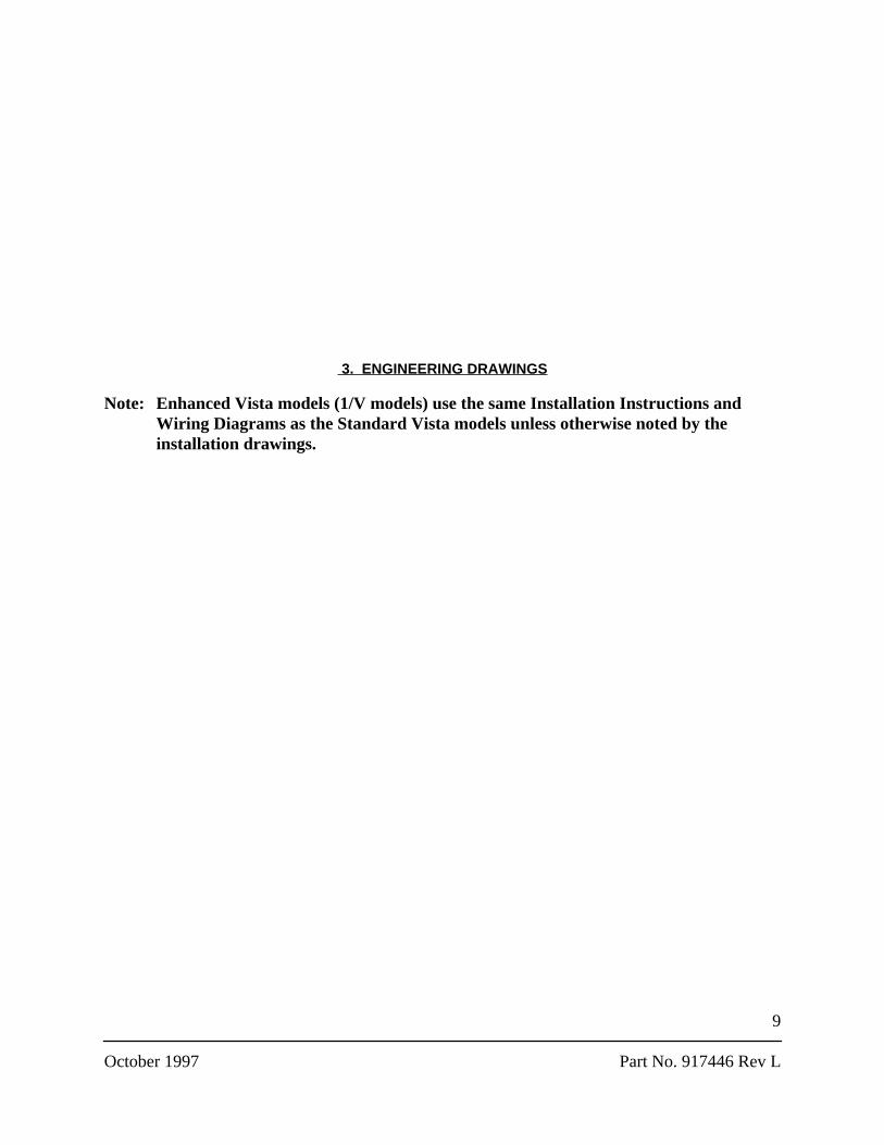
3. ENGINEERING DRAWINGS
Note: Enhanced Vista models (1/V models) use the same Installation Instructions and Wiring Diagrams as the Standard Vista models unless otherwise noted by the installation drawings.
10Part No. 917446 R
ev LO
ctober 1997
FIGURE 3-1. 10205-B VISTA FIELD LIFTING INSTRUCTION.
11
October 1997
Part No. 917446 R
ev L FIGURE 3-2. 7115-C VALANCE INSTALLATION INSTRUCTIONS.
12Part No. 917446 R
ev LO
ctober 1997 FIGURE 3-3. 6595-D LIGHTED VALANCE INSTALLATION INSTRUCTION.
13
October 1997
Part No. 917446 R
ev L
FIGURE 3-4. 1-7133-C INSTALLATION INSTRUCTIONS - V390D, X/V390D AND V390D/U SERIES (REMOTE).
14Part No. 917446 R
ev LO
ctober 1997
FIGURE 3-5. 2-7133-C INSTALLATION INSTRUCTIONS - V399D SERIES (REMOTE).
15
October 1997
Part No. 917446 R
ev L
FIGURE 3-6. 3-7133-C INSTALLATION INSTRUCTIONS - V490D AND X/V490D/U SERIES W/O WAYNE VAC.
16Part No. 917446 R
ev LO
ctober 1997
FIGURE 3-7. 9-7133-C INSTALLATION INSTRUCTIONS - V490D/V W/O WAYNE VAC SERIES (LOW HOSE).
17
October 1997
Part No. 917446 R
ev L
FIGURE 3-8. 21-7133-C INSTALLATION INSTRUCTIONS - V390P AND V390P/U SERIES (SUCTION).
18Part No. 917446 R
ev LO
ctober 1997
FIGURE 3-9. 23-7133-C INSTALLATION INSTRUCTIONS - V389P SERIES (SUCTION).
19
October 1997
Part No. 917446 R
ev L
FIGURE 3-10. 24-7133-C INSTALLATION INSTRUCTIONS - V387D SERIES (REMOTE).
20Part No. 917446 R
ev LO
ctober 1997
FIGURE 3-11. 25-7133-C INSTALLATION INSTRUCTIONS - V388D AND V389D SERIES (REMOTE).
21
October 1997
Part No. 917446 R
ev L
FIGURE 3-12. 27-7133-C INSTALLATION INSTRUCTIONS - V387P SERIES (SUCTION).
22Part No. 917446 R
ev LO
ctober 1997
FIGURE 3-13. 29-7133-C INSTALLATION INSTRUCTIONS - V490D AND X/V490D/U SERIES W/ WAYNE VAC (REMOTE).
23
October 1997
Part No. 917446 R
ev L
FIGURE 3-14. 30-7133-C INSTALLATION INSTRUCTIONS - V399P SERIES (SUCTION).
24Part No. 917446 R
ev LO
ctober 1997 FIGURE 3-15. 1-7157-C INSTALLATION WIRING DIAGRAM - V390D SERIES (REMOTE).
25
October 1997
Part No. 917446 R
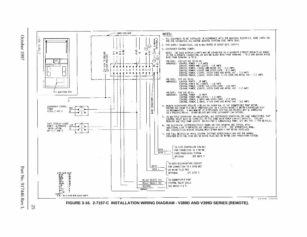
ev L FIGURE 3-16. 2-7157-C INSTALLATION WIRING DIAGRAM - V389D AND V399D SERIES (REMOTE).
26Part No. 917446 R
ev LO
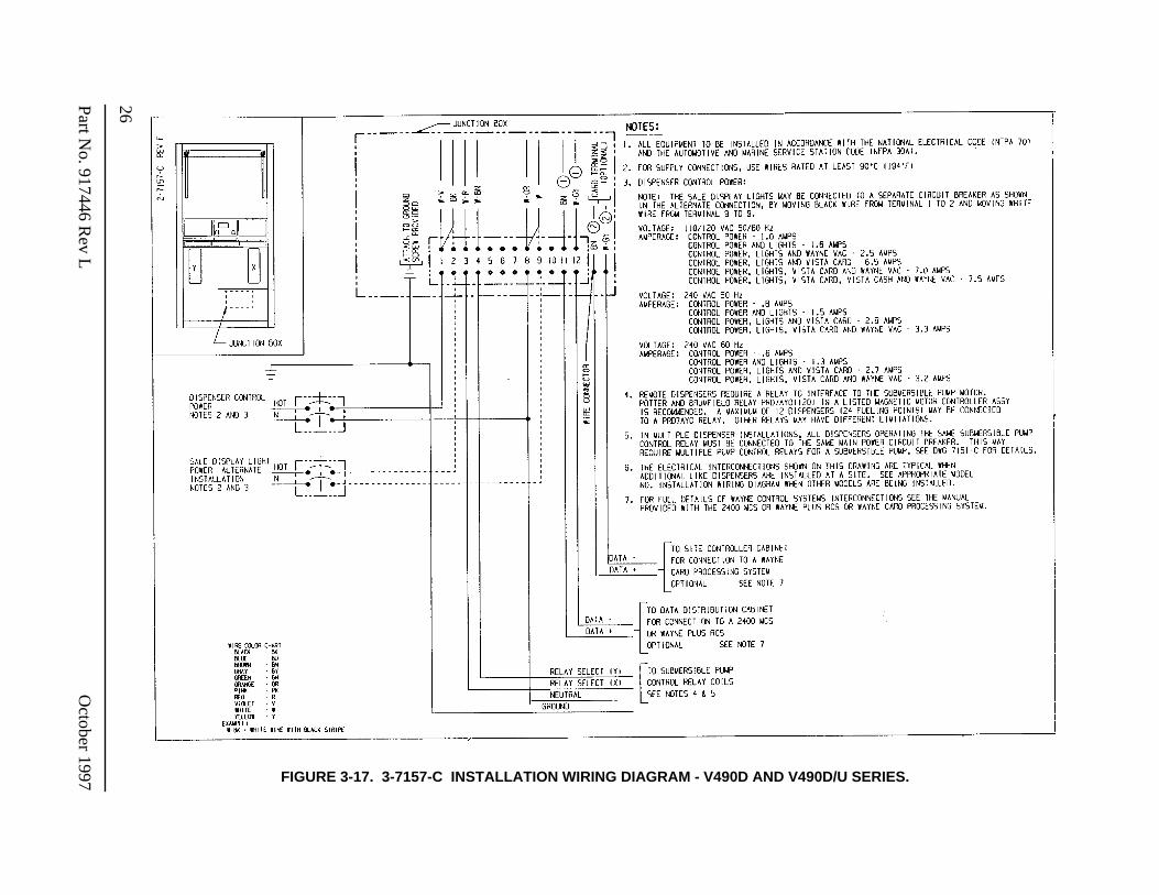
ctober 1997 FIGURE 3-17. 3-7157-C INSTALLATION WIRING DIAGRAM - V490D AND V490D/U SERIES.
27
October 1997
Part No. 917446 R
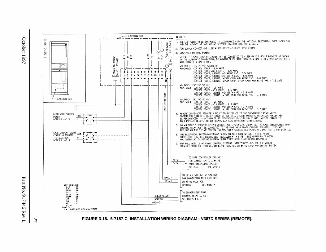
ev L FIGURE 3-18. 5-7157-C INSTALLATION WIRING DIAGRAM - V387D SERIES (REMOTE).
28Part No. 917446 R
ev LO
ctober 1997
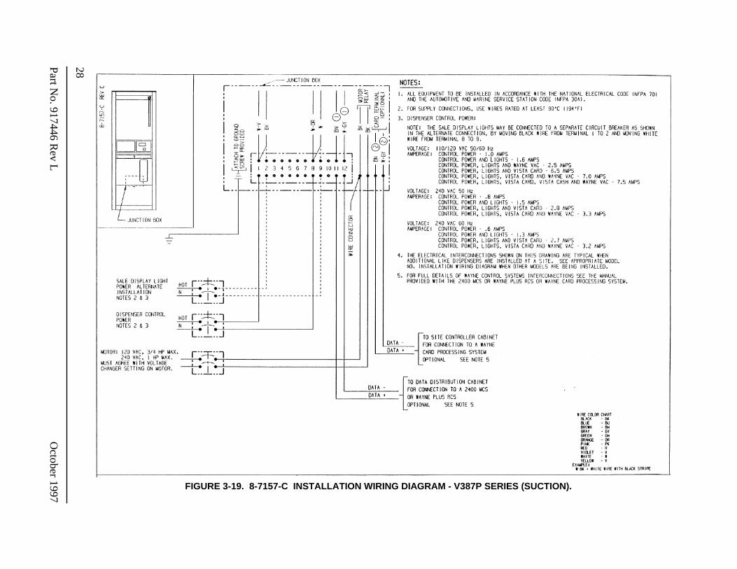
FIGURE 3-19. 8-7157-C INSTALLATION WIRING DIAGRAM - V387P SERIES (SUCTION).
29
October 1997
Part No. 917446 R
ev L FIGURE 3-20. 9-7157-C INSTALLATION WIRING DIAGRAM - V389P AND V399P SERIES (SUCTION).
30Part No. 917446 R
ev LO
ctober 1997 FIGURE 3-21. 13-7157-C INSTALLATION WIRING DIAGRAM - V390D/U SERIES (REMOTE).
31
October 1997
Part No. 917446 R
ev L FIGURE 3-22. 6-7157-C INSTALLATION WIRING DIAGRAM - V390P AND V390P/U SERIES (SUCTION).
32Part No. 917446 R
ev LO
ctober 1997
FIGURE 3-23. 7151-C TYPICAL DISPENSER SITE WIRING DIAGRAM.
33
October 1997
Part No. 917446 R
ev L FIGURE 3-24. 1887-A INSTALLATION WIRING DIAGRAM - DISPENSER INTERCOM AND CALL BUTTON.
34Part No. 917446 R
ev LO
ctober 1997 FIGURE 3-25. 5-7161-C INSTRUCTION - REDIRECTION OF VENT LINE FOR VAPOR RECOVERY - MODEL V390P.
35
October 1997
Part No. 917446 R
ev L FIGURE 3-26. 7-7161-C INSTRUCTION - REDIRECTION OF VENT LINE FOR VAPOR RECOVERY - MODEL V388P AND V389P.
36Part No. 917446 R
ev LO
ctober 1997 FIGURE 3-27. 8-7161-C INSTRUCTIONS - REDIRECTION OF VENT LINE FOR VAPOR RECOVERY - MODEL V387P.

37
October 1997
Part No. 917446 R
ev L FIGURE 3-28. 10196-B DIMENSIONAL DRAWING - INSIDE FOOTPRINT.

38
Part No. 917446 Rev L October 1997
39
October 1997 Part No. 917446 Rev L
4. DISPENSER INTERCONNECTION WIRING DIAGRAMS
40Part No. 917446 R
ev LO
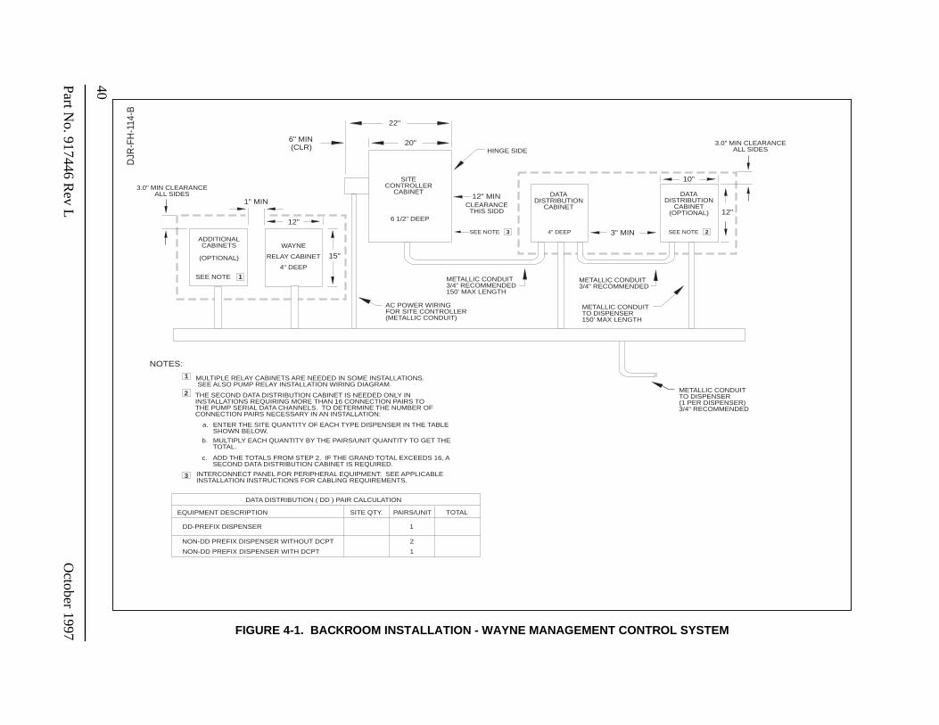
ctober 1997 FIGURE 4-1. BACKROOM INSTALLATION - WAYNE MANAGEMENT CONTROL SYSTEM
BACK ROOM INSTALLATIONWAYNE MANAGEMENT CONTROL SYSTEM
DJR
-FH
-114
-B
MULTIPLE RELAY CABINETS ARE NEEDED IN SOME INSTALLATIONS. SEE ALSO PUMP RELAY INSTALLATION WIRING DIAGRAM.
12"12"
6" MIN(CLR)
22"
20"
12" MIN
3" MIN
10"
HINGE SIDE
METALLIC CONDUIT3/4" RECOMMENDED
AC POWER WIRINGFOR SITE CONTROLLER(METALLIC CONDUIT)
METALLIC CONDUIT3/4" RECOMMENDED150' MAX LENGTH
METALLIC CONDUITTO DISPENSER150' MAX LENGTH
CLEARANCETHIS SIDD
1" MIN
3.0" MIN CLEARANCEALL SIDES
METALLIC CONDUITTO DISPENSER(1 PER DISPENSER)3/4" RECOMMENDED
NOTES:
15"
ADDITIONALCABINETS
(OPTIONAL)
SEE NOTE 1
WAYNE
RELAY CABINET
4" DEEP
THE SECOND DATA DISTRIBUTION CABINET IS NEEDED ONLY ININSTALLATIONS REQUIRING MORE THAN 16 CONNECTION PAIRS TOTHE PUMP SERIAL DATA CHANNELS. TO DETERMINE THE NUMBER OFCONNECTION PAIRS NECESSARY IN AN INSTALLATION:
ENTER THE SITE QUANTITY OF EACH TYPE DISPENSER IN THE TABLESHOWN BELOW.
1
2
a.
b.
c.
3.0" MIN CLEARANCEALL SIDES
MULTIPLY EACH QUANTITY BY THE PAIRS/UNIT QUANTITY TO GET THETOTAL.
ADD THE TOTALS FROM STEP 2. IF THE GRAND TOTAL EXCEEDS 16, ASECOND DATA DISTRIBUTION CABINET IS REQUIRED.
SEE NOTE 3
3 INTERCONNECT PANEL FOR PERIPHERAL EQUIPMENT: SEE APPLICABLEINSTALLATION INSTRUCTIONS FOR CABLING REQUIREMENTS.
DATA DISTRIBUTION ( DD ) PAIR CALCULATION
EQUIPMENT DESCRIPTION
DD-PREFIX DISPENSER
NON-DD PREFIX DISPENSER WITHOUT DCPT
SITE QTY. PAIRS/UNIT TOTAL
1
NON-DD PREFIX DISPENSER WITH DCPT 1
2
metallic wireway (customer supplied)
SITECONTROLLER
CABINET
6 1/2" DEEP
4" DEEP
DATADISTRIBUTION
CABINET
SEE NOTE 2
DATADISTRIBUTION
CABINET(OPTIONAL)
41
October 1997
Part No. 917446 R
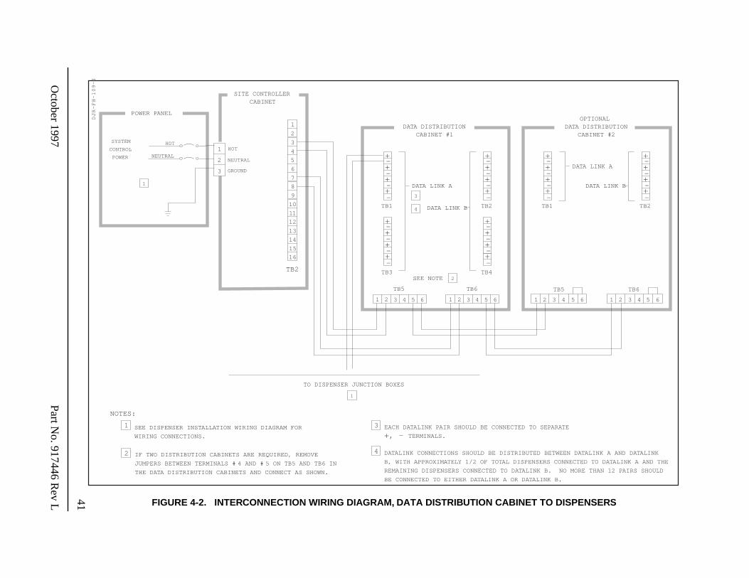
ev L FIGURE 4-2. INTERCONNECTION WIRING DIAGRAM, DATA DISTRIBUTION CABINET TO DISPENSERS
1
DJ
R-F
H-1
09
-I
DATA LINK A
DATA LINK BTB1 TB2
TB3 TB4
DATA LINK A
61 2 3 4 5 6
TB5 TB6
1 2 3 4 5
TB1
TB2
12
16
1
2
3
4
5
6
7
8
9
10
11
13
14
15
NOTES:
1
2
3
SYSTEM
CONTROL
POWER NEUTRAL
HOT
NEUTRAL
HOT
GROUND
SITE CONTROLLERCABINET
OPTIONALDATA DISTRIBUTION
CABINET #2
3
4TB2
DATA LINK B
TB5
1 2 3 4 5 6
+-+-+-+-
+-+-+-+-
+-+-+-+-
+-+-+-+-
TB6
1 2 3 4 5 6
POWER PANEL
DATA DISTRIBUTIONCABINET #1
TO DISPENSER JUNCTION BOXES
SEE NOTE
1
SEE DISPENSER INSTALLATION WIRING DIAGRAM FOR
WIRING CONNECTIONS.
IF TWO DISTRIBUTION CABINETS ARE REQUIRED, REMOVE
JUMPERS BETWEEN TERMINALS # 4 AND # 5 ON TB5 AND TB6 IN
THE DATA DISTRIBUTION CABINETS AND CONNECT AS SHOWN.
1
2
3 EACH DATALINK PAIR SHOULD BE CONNECTED TO SEPARATE
+, - TERMINALS.
4 DATALINK CONNECTIONS SHOULD BE DISTRIBUTED BETWEEN DATALINK A AND DATALINK
B, WITH APPROXIMATELY 1/2 OF TOTAL DISPENSERS CONNECTED TO DATALINK A AND THE
REMAINING DISPENSERS CONNECTED TO DATALINK B. NO MORE THAN 12 PAIRS SHOULD
BE CONNECTED TO EITHER DATALINK A OR DATALINK B.
+-+-+-+-
+-+-+-+-
2
42Part No. 917446 R
ev LO
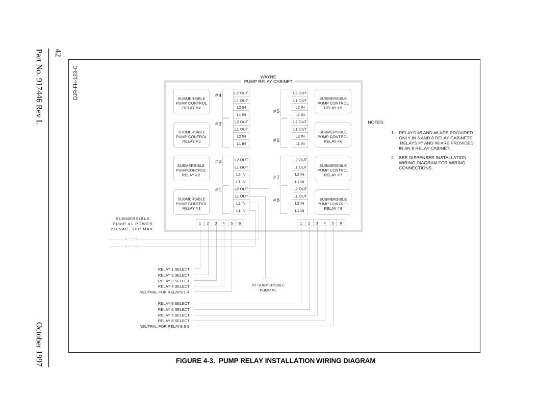
ctober 1997 FIGURE 4-3. PUMP RELAY INSTALLATION WIRING DIAGRAM
DJR
-FH
-123
-C
SUBMERSIBLEPUMP CONTROL
RELAY # 4
SUBMERSIBLEPUMP CONTROL
RELAY # 3
SUBMERSIBLEPUMPCONTROL
RELAY # 2
SUBMERSIBLEPUMP CONTROL
RELAY # 1
SUBMERSIBLEPUMP CONTROL
RELAY # 5
SUBMERSIBLEPUMP CONTROL
RELAY # 6
SUBMERSIBLEPUMP CONTROL
RELAY # 7
SUBMERSIBLEPUMP CONTROL
RELAY # 8
L2 OUT
L1 OUT
L2 IN
L1 IN
L2 OUT
L1 OUT
L2 IN
L1 IN
L2 OUT
L1 OUT
L2 IN
L1 IN
L2 OUT
L1 OUT
L2 IN
L1 IN
#4
#5
#3
#6
L2 OUT
L1 OUT
L2 IN
L1 IN
L2 OUT
L1 OUT
L2 IN
L1 IN
L2 OUT
L1 OUT
L2 IN
L1 IN
L2 OUT
L1 OUT
L2 IN
L1 IN
#2
#7
#1
WAYNEPUMP RELAY CABINET
1 2 543 6
RELAY 1 SELECT
RELAY 2 SELECT
RELAY 3 SELECT
RELAY 4 SELECT
NEUTRAL FOR RELAYS 1-4
1 2 543 6
RELAY 5 SELECT
RELAY 6 SELECT
RELAY 7 SELECT
RELAY 8 SELECT
NEUTRAL FOR RELAYS 5-8
NOTES:
1. RELAYS #5 AND #6 ARE PROVIDEDONLY IN 6 AND 8 RELAY CABINETS. RELAYS #7 AND #8 ARE PROVIDEDIN AN 8 RELAY CABINET.
2. SEE DISPENSER INSTALLATIONWIRING DIAGRAM FOR WIRINGCONNECTIONS.
#8
S U B M E R S I B L EP U M P # 1 P O W E R
2 4 0 VA C , 1 H P M A X .
TO SUBMERSIBLEPUMP #1
43
October 1997
Part No. 917446 R
ev L
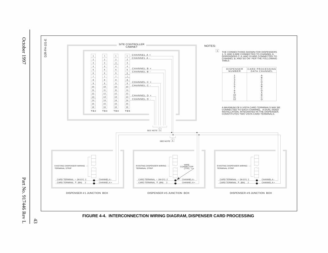
FIGURE 4-4. INTERCONNECTION WIRING DIAGRAM, DISPENSER CARD PROCESSING
1
2
3
4
5
6
7
8
9
10
11
12
13
14
15
16
1
2
3
4
5
6
7
8
9
10
11
12
13
14
15
16
1
2
3
4
5
6
7
8
9
10
11
12
13
14
15
16
1
2
3
4
5
6
7
8
9
10
11
12
13
14
15
16
T B 2 T B 4 T B 5T B 3
C H A N N E L A +
C H A N N E L A -
C H A N N E L B +
C H A N N E L B -
C H A N N E L C +
C H A N N E L C -
C H A N N E L D +
C H A N N E L D -
NOTES:
1
DJR
-FH
-101
-E
WIRING DIAGRAM, DISPENSER CARD PROCESSING
THE CONNECTIONS SHOWN FOR DISPENSERS1, 5, AND 9 ARE CONNECTED TO CHANNEL A.DISPENSERS 2, 6, AND 10 ARE CONNECTED TOCHANNEL B, AND SO ON PER THE FOLLOWINGTABLE:
A MAXIMUM OF 6 VISTA CARD TERMINALS MAY BECONNECTED TO EACH CHANNEL. A DUAL SIDEDINSTALLATION, INTEGRATED IN THE DISPENSER,CONSTITUTES TWO VISTA CARD TERMINALS.
CHANNEL A -
CHANNEL A +
DISPENSER #9 JUNCTION BOX
CHANNEL A -CARD TERMINAL - (W-GY) 2
CARD TERMINAL + (BN) 2 CHANNEL A +
EXISTING DISPENSER WIRINGTERMINAL STRIP
DISPENSER #1 JUNCTION BOX
CHANNEL A -
CHANNEL A +
DISPENSER #5 JUNCTION BOX
SITE CONTROLLERCABINET
D I S P E N S E RN U M B E R
123456789
101112
C A R D P R O C E S S I N GD ATA C H A N N E L
ABCDABCDABCD
SEE NOTE
SEE NOTE 1
1
EXISTING DISPENSER WIRINGTERMINAL STRIP
EXISTING DISPENSER WIRINGTERMINAL STRIP
CARD TERMINAL - (W-GY) 2
CARD TERMINAL + (BN) 2
CARD TERMINAL - (W-GY) 2
CARD TERMINAL + (BN) 2
WIRECONNECTOR
(TYP)

44
Part No. 917446 Rev L October 1997
WARRANTY AND LIMITATION OF REMEDY AND LIABILITY
Seller warrants that new products and parts of its own design and manufacture when shipped, will be of good quality and will be free from defects in material and workmanship and will conform to applicable specifications. Work, when performed by Seller, will meet applicable work require-ments. No warranty is made with respect to used or rebuilt equipment and with respect to products not manufactured by Seller. Seller’s only obligation shall be to assign to Buyer, at the time of sale, whatever warranty Seller has received from the manufacturer. Items such as but not limited to lamps, electric motors, hoses, nozzles, hose swivels and safety impact valves are included in the category referred to in the previous sentence. Seller’s recommendations with respect to the oper-ation of Seller’s equipment are advisory only and are not warranted. All claims under this warranty must be made in writing immediately upon discovery and, in any event, within twenty-four (24) months from date of start-up, if a product is involved, or from completion of the applicable work, if work is involved, or thirty (30) months from date of invoice (whichever shall occur first). (Pro-vided however, that with respect to the Wayne Plus system, 2400 system, DL series dispensers, and card readers, all claims must be made in writing within twelve (12) months from date of start-up. With respect to receipts/totals printers, and any other printers or printing mechanisms, all claims must be made in writing within ninety (90) days from date of start-up. Wayne Vista dis-penser external metal panels will be free from defects due to rust and/or corrosion for a period of forty-eight (48) months from date of dispenser start-up.) Defective and nonconforming items must be held for Seller’s inspection and returned to the original f.o.b. point upon request. Seller’s war-ranty on service parts, whether new or reconditioned, is ninety (90) days from the date of installa-tion, or twelve (12) months from date of invoice, whichever first occurs. THE FOREGOING IS EXPRESSLY IN LIEU OF ALL OTHER WARRANTIES WHATSOEVER, EXPRESSED, IM-PLIED AND STATUTORY, INCLUDING WITHOUT LIMITATIONS, THE IMPLIED WAR-RANTIES OF MERCHANTABILITY AND FITNESS.
Upon Buyer’s submission of a claim as provided above and its substantiation, Seller shall, at its option either (I) repair or replace its product or work at the original f.o.b. point or location of pur-chase products and/or parts or (II) refund an equitable portion of the purchase price.
THE FOREGOING IS SELLER’S ONLY OBLIGATION AND BUYER’S EXCLUSIVE REM-EDY FOR BREACH OF WARRANTY AND, EXCEPT FOR GROSS NEGLIGENCE ORWILLFUL MISCONDUCT, THE FOREGOING IS BUYER’S EXCLUSIVE REMEDYAGAINST SELLER FOR ALL CLAIMS ARISING HEREUNDER OR RELATING HERETOWHETHER SUCH CLAIMS ARE BASED ON BREACH OF CONTRACT, TORT (INCLUD-ING NEGLIGENCE AND STRICT LIABILITY) OR OTHER THEORIES. BUYER’S FAILURETO SUBMIT A CLAIM AS PROVIDED ABOVE SHALL SPECIFICALLY WAIVE ALLCLAIMS FOR DAMAGES OR OTHER RELIEF, INCLUDING BUT NOT LIMITED TOCLAIMS BASED ON LATENT DEFECTS. IN NO EVENT SHALL BUYER BE ENTITLEDTO INCIDENTAL OR CONSEQUENTIAL DAMAGES. ANY ACTION BY BUYER ARISINGHEREUNDER OR RELATING HERETO, WHETHER BASED ON BREACH OF CONTRACT,TORT (INCLUDING NEGLIGENCE AND STRICT LIABILITY) OR OTHER THEORIES,MUST BE COMMENCED WITHIN ONE (1) YEAR AFTER THE CAUSE OF ACTION AC-CRUES OR IT SHALL BE BARRED.
"NOTE: This equipment has been tested and found to comply with the limits for a Class A digital device, pursuant to Part 15 of the FCC Rules. These limits are designed to provide reasonable protection against harmful interference when the equipment is operated in a com-mercial environment. This equipment generates, uses, and can radiate radio frequency energy and, if not installed and used in accordance with the instruction manual, may cause harmful interference to radio communications. Operation of this equipment in a residential area is likely to cause harmful interference in which case the user will be re-quired to correct the interference at his own expense."
917446 L
Wayne Division, Dresser Industries Inc., P.O. Box 1859, Salisbury, MD 21802-1859, (410) 546-6600
Part No. 917446 Rev L 10/97 ©1997 Dresser Industries, Inc. 500/10/97