Visit Installation and Start-Up Instructions · Visit Manufacturer reserves the right to...
28
ZONECC(2,4,8)KIT-B Installation and Start-Up Instructions TABLE OF CONTENTS Page SAFETY CONSIDERATIONS...................................................1 INSTALLATION CONSIDERATIONS....................................1 INTRODUCTION .....................................................................1-2 INSTALLATION ......................................................................2-8 • Check Equipment And Job Site..................................................2 • Component Location And Wiring Considerations .....................2 • Install Components...................................................................2-3 • Install Zone Dampers ...............................................................3-5 • Install Barometric Bypass Damper .............................................5 • Install Leaving Air Temperature (LAT) Sensor.........................5 • Install Heat Pump Temperature (HPT) Sensor ..........................5 • Final Wiring..................................................................5-8, 21-28 • Understanding Sequence Of Operation ...................................6-8 SYSTEM CONFIGURATION ..............................................8-12 • Equipment Controller Configuration .......................................8-9 • User Interface Configuration .................................................9-12 SYSTEM STARTUP AND CHECKOUT..........................12-13 • Enable Installer Setup Mode .....................................................12 • Check Damper And Sensor Operation ................................12-13 • Quick Check Of Equipment Operation ....................................13 • Longer Check Of Equipment Operation...................................13 FINAL INSTALLATION SETTINGS ...............................13-16 OPERATIONAL INFORMATION .........................................16 QUICK START.....................................................................16-17 QUICK PROGRAMMING OF COMFORT SCHEDULES.17 HOLD, OFF, OUT AND ALL ZONE................................17-19 SMART SENSOR OPERATION............................................ 18 TROUBLESHOOTING .......................................................19-20 NOTE: Read the entire instruction manual before starting the installation. This symbol → indicates a change since the last issue. SAFETY CONSIDERATIONS Improper installation, adjustment, alteration, service, maintenance, or use can cause fire, electrical shock, or other conditions which may cause personal injury or property damage. Consult a qualified installer, service agency or your distributor or branch for informa- tion or assistance. The qualified installer or agency must use factory-authorized kits or accessories when modifying this prod- uct. Refer to the individual instructions packaged with the kits or accessories when installing. Follow all safety codes and wear safety glasses. Have fire extinguisher available. Read these instructions thoroughly and follow all warnings or cautions attached to the unit. Consult local and state building codes and Sheet Metal and Air Conditioning National Association (SMACNA) for special installation require- ments. Recognize safety information. This is the safety-alert symbol . When you see this symbol on the unit or in instructions and manuals, be alert to the potential for personal injury. Understand the signal words DANGER, WARNING, and CAU- TION. These words are used with the safety-alert symbol. DAN- GER identifies the most serious hazards which will result in severe personal injury or death. WARNING signifies hazards which could result in personal injury or death. CAUTION is used to identify unsafe practices which would result in minor personal injury or product and property damage. INSTALLATION CONSIDERATIONS Before the actual installation of a zoning system can begin, decisions need to be made to determine the number and location of zones and sensors. This affects duct and damper selections. For assistance with these decisions, consult the Zoning Design Guide available from your distributor or branch. This instruction covers the physical installation and start up of the Comfort Zone II -B system. Use this instruction to guide the actual installation process after all the air side decisions have been made. 1. Install User Interface and Remote Sensors in non-condensing areas with ambients between 32°F and 120°F. Install Dampers and Equipment Controller in non-condensing areas with ambients between 32°F and 158°F. 2. A TXV is required on the indoor coil when used with all residential split system equipment. 3. Use separate isolated transformer to supply power to Comfort Zone II -B System (40 va minimum, class 2, field supplied). 4. Proper equipment and duct sizing are important in a zoned system. Be sure to refer to the Zoning Design Guide for assistance in making these selections. TXV on indoor coil is required with all residential split system equipment. INTRODUCTION The Comfort Zone II -B System allows air conditioning and heating equipment to control temperatures and humidity in up to 8 distinct spaces or Zones within a building. Each zone has inde- pendent temperature settings. The comfort temperature settings can change automatically through the use of schedules. This allows Comfort Zone II -B to change temperature settings in zones to reflect occupancy or usage. For example, you can condition the bedrooms in a home from 5:00 PM through 7:00 AM or the kitchen from 3:00 PM through 6:00 PM. The Comfort Zone II -B System uses motorized air volume control dampers (also called zone dampers) to regulate flow of conditioned air into zones. In this manner Comfort Zone II -B can selectively heat or cool certain portions of a building depending upon space temperature requirements. Each zone requires a motorized zone damper to control the air supplied to it and a zone sensor to sense zone temperature. There are 4 types of zone sensors available and they may be used in combination: Visit www.carrier.com Manufacturer reserves the right to discontinue, or change at any time, specifications or designs without notice and without incurring obligations. Book 1 1 4 4 Tab 3a 5a 2a 5a PC 101 Catalog No. 809-538 Printed in U.S.A. Form ZONEKIT-14SI Pg 1 12-99 Replaces: ZONEKIT-13SI
Transcript of Visit Installation and Start-Up Instructions · Visit Manufacturer reserves the right to...

ZONECC(2,4,8)KIT-B
Installation and Start-Up Instructions
TABLE OF CONTENTS
Page
SAFETY CONSIDERATIONS ...................................................1INSTALLATION CONSIDERATIONS ....................................1INTRODUCTION .....................................................................1-2INSTALLATION ......................................................................2-8• Check Equipment And Job Site..................................................2• Component Location And Wiring Considerations .....................2• Install Components...................................................................2-3• Install Zone Dampers...............................................................3-5• Install Barometric Bypass Damper .............................................5• Install Leaving Air Temperature (LAT) Sensor.........................5• Install Heat Pump Temperature (HPT) Sensor ..........................5• Final Wiring..................................................................5-8, 21-28• Understanding Sequence Of Operation ...................................6-8SYSTEM CONFIGURATION ..............................................8-12• Equipment Controller Configuration .......................................8-9• User Interface Configuration .................................................9-12SYSTEM STARTUP AND CHECKOUT ..........................12-13• Enable Installer Setup Mode.....................................................12• Check Damper And Sensor Operation................................12-13• Quick Check Of Equipment Operation ....................................13• Longer Check Of Equipment Operation...................................13FINAL INSTALLATION SETTINGS ...............................13-16OPERATIONAL INFORMATION .........................................16QUICK START .....................................................................16-17QUICK PROGRAMMING OF COMFORT SCHEDULES .17HOLD, OFF, OUT AND ALL ZONE ................................17-19SMART SENSOR OPERATION............................................ 18TROUBLESHOOTING .......................................................19-20
NOTE: Read the entire instruction manual before starting theinstallation.
This symbol→ indicates a change since the last issue.
SAFETY CONSIDERATIONS
Improper installation, adjustment, alteration, service, maintenance,or use can cause fire, electrical shock, or other conditions whichmay cause personal injury or property damage. Consult a qualifiedinstaller, service agency or your distributor or branch for informa-tion or assistance. The qualified installer or agency must usefactory-authorized kits or accessories when modifying this prod-uct. Refer to the individual instructions packaged with the kits oraccessories when installing.
Follow all safety codes and wear safety glasses. Have fireextinguisher available. Read these instructions thoroughly andfollow all warnings or cautions attached to the unit. Consult localand state building codes and Sheet Metal and Air ConditioningNational Association (SMACNA) for special installation require-ments.
Recognize safety information. This is the safety-alert symbol.When you see this symbol on the unit or in instructions andmanuals, be alert to the potential for personal injury.
Understand the signal words DANGER, WARNING, and CAU-TION. These words are used with the safety-alert symbol. DAN-GER identifies the most serious hazards whichwill result in severepersonal injury or death. WARNING signifies hazards whichcould result in personal injury or death. CAUTION is used toidentify unsafe practices whichwould result in minor personalinjury or product and property damage.
INSTALLATION CONSIDERATIONSBefore the actual installation of a zoning system can begin,decisions need to be made to determine the number and location ofzones and sensors. This affects duct and damper selections. Forassistance with these decisions, consult the Zoning Design Guideavailable from your distributor or branch.
This instruction covers the physical installation and start up of theComfort Zone II -B system. Use this instruction to guide the actualinstallation process after all the air side decisions have been made.
1. Install User Interface and Remote Sensors in non-condensingareas with ambients between 32°F and 120°F. Install Dampersand Equipment Controller in non-condensing areas withambients between 32°F and 158°F.
2. A TXV is required on the indoor coil when used with allresidential split system equipment.
3. Use separate isolated transformer to supply power to ComfortZone II -B System (40 va minimum, class 2, field supplied).
4. Proper equipment and duct sizing are important in a zonedsystem. Be sure to refer to the Zoning Design Guide forassistance in making these selections.
TXV on indoor coil is required with all residential splitsystem equipment.
INTRODUCTIONThe Comfort Zone II -B System allows air conditioning andheating equipment to control temperatures and humidity in up to 8distinct spaces or Zones within a building. Each zone has inde-pendent temperature settings.The comfort temperature settings can change automaticallythrough the use of schedules. This allows Comfort Zone II -B tochange temperature settings in zones to reflect occupancy or usage.For example, you can condition the bedrooms in a home from 5:00PM through 7:00 AM or the kitchen from 3:00 PM through 6:00PM. The Comfort Zone II -B System uses motorized air volumecontrol dampers (also called zone dampers) to regulate flow ofconditioned air into zones. In this manner Comfort Zone II -B canselectively heat or cool certain portions of a building dependingupon space temperature requirements.
Each zone requires a motorized zone damper to control the airsupplied to it and a zone sensor to sense zone temperature. Thereare 4 types of zone sensors available and they may be used incombination:
Visit www.carrier.com
Manufacturer reserves the right to discontinue, or change at any time, specifications or designs without notice and without incurring obligations.Book 1 1 4 4Tab 3a 5a 2a 5a
PC 101 Catalog No. 809-538 Printed in U.S.A. Form ZONEKIT-14SI Pg 1 12-99 Replaces: ZONEKIT-13SI
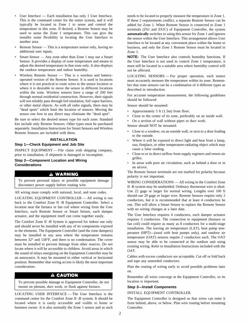
• User Interface — Each installation has only 1 User Interface.This is the command center for the entire system, and it willtypically be located in Zone 1 to sense and control thetemperature in this zone. If desired, a Remote Sensor may beused to sense the Zone 1 temperature. This can give theinstaller some flexibility in locating the User Interface toanother area.
• Remote Sensor — This is a temperature sensor only, having noadditional user inputs.
• Smart Sensor — Any zone other than Zone 1 may use a SmartSensor. It provides a display of zone temperature and means toadjust the desired temperature in that zone only. It also displaysthe outdoor temperature and indoor humidity.
• Wireless Remote Sensor — This is a wireless and battery-operated version of the Remote Sensor. It is used in locationswhere it is not practical to route wires to the sensor location orwhere it is desirable to move the sensor to different locationswithin the zone. Wireless sensors have a range of 200 feetthrough normal residential construction. However, their signalswill not reliably pass through foil insulation, foil vapor barriers,or other metal objects. As with all radio signals, there may be"dead spots" which limit the location of sensors. Moving thesensor one foot in any direct may eliminate the "dead spot".
Be sure to select the desired sensor type for each zone. Standardkits include only Remote Sensors. Other types must be purchasedseparately. Installation Instructions for Smart Sensors and WirelessRemote Sensors are included with them.
INSTALLATIONStep 1—Check Equipment and Job Site
INSPECT EQUIPMENT — File claim with shipping company,prior to installation, if shipment is damaged or incomplete.
Step 2—Component Location and WiringConsiderations
To prevent personal injury or possible equipment damagedisconnect power supply before routing wire.
All wiring must comply with national, local, and state codes.
LOCATING EQUIPMENT CONTROLLER — All wiring is runback to the Comfort Zone II -B Equipment Controller. Select alocation near the furnace or fan coil where wiring from the UserInterface, each Remote Sensor or Smart Sensor, each damperactuator, and the equipment itself can come together easily.
The Comfort Zone II -B System is approved for indoor use onlyand should never be installed with any of its components exposedto the elements. The Equipment Controller (and the zone dampers)may be installed in any area where the temperature remainsbetween 32° and 158°F, and there is no condensation. The covermust be installed to prevent damage from other sources. Do notlocate where it will be accessible to children. Avoid areas in whichthe sound of relays energizing on the Equipment Controller may bean annoyance. It may be mounted in either vertical or horizontalposition. Remember that wiring access is likely the most importantconsideration.
To prevent possible damage to Equipment Controller, do notmount on plenum, duct work, or flush against furnace.
LOCATING USER INTERFACE — The User Interface is thecommand center for the Comfort Zone II -B system. It should belocated where it is easily accessible and visible to home orbusiness owner. It is also normally the Zone 1 sensor and as such
needs to be located to properly measure the temperature in Zone 1.If these 2 requirements conflict, a separate Remote Sensor can beadded for Zone 1. When Remote Sensor is connected to Zone 1terminals (ZS1 and ZS1C) of Equipment Controller, the systemautomatically switches to using this sensor for Zone 1 and ignoresthe sensor within the User Interface. This arrangement allows UserInterface to be located at any convenient place within the home orbusiness, and only the Zone 1 Remote Sensor must be located inZone 1.NOTE: The User Interface also controls humidity functions. Ifthe User Interface is not used to control Zone 1 temperature, itmust still be located in a suitable area where humidity control willnot be affected.
LOCATING SENSORS — For proper operation, each sensormust accurately measure the temperature within its zone. Remem-ber that zone sensors can be a combination of 4 different types asdescribed in introduction.
For accurate temperature measurement, the following guidelinesshould be followed:
Sensor should be mounted:
• Approximately 5 ft (1.5m) from floor.• Close to the center of its zone, preferably on an inside wall.• On a section of wall without pipes or duct work.Sensor should NOT be mounted:
• Close to a window, on an outside wall, or next to a door leadingto the outside.
• Where it will be exposed to direct light and heat from a lamp,sun, fireplace, or other temperature-radiating object which maycause a false reading.
• Close to or in direct airflow from supply registers and return-airgrilles.
• In areas with poor air circulation, such as behind a door or inan alcove.
The Remote Sensor terminals are not marked for polarity becausepolarity is not important.
WIRING CONSIDERATIONS — All wiring in the Comfort ZoneII -B system may be unshielded. Ordinary thermostat wire is ideal.Use 22 gage or larger for normal wiring. Lengths over 100 ftshould use 20 gage or larger wire. Remote Sensors require only 2conductors, but it is recommended that at least 4 conductors berun. This will allow a Smart Sensor to replace the Remote Sensorwith no wiring changes at a later date.
The User Interface requires 4 conductors, each damper actuatorrequires 3 conductors. The connection to equipment (furnace orfan coil) could require as many as 8 conductors for a multi-stageinstallation. The leaving air temperature (LAT), heat pump tem-perature (HPT)—(used with heat pumps only), and outdoor airtemperature (OAT) sensors require 2 conductors each. The OATsensor may be able to be connected at the outdoor unit usingexisting wiring. Refer to Installation Instructions included with theOAT.
Cables with excess conductors are acceptable. Cut off or fold backand tape any unneeded conductors.
Plan the routing of wiring early to avoid possible problems lateron.
Remember all wires converge at the Equipment Controller, so itslocation is important.
Step 3—Install Components
INSTALL EQUIPMENT CONTROLLER
The Equipment Controller is designed so that wires can enter itfrom behind, above, or below. Plan wire routing before mountingController.
2

1. Open doors or remove cover to access mounting holes(remove the 2 Zone system cover from the left side first).
2. Mount back plate to wall using screws and wall anchorsprovided.
3. Level back plate and tighten screws.
INSTALL USER INTERFACE
1. Open User Interface rear door (mounting base) to exposemounting holes. Press back half of the right end inward andthen pull front and back halves apart at the right end to open.The mounting base (the back half of the plastic) can beseparated from the User Interface body by snapping the hingeapart.
a. Remove hinged cover by snapping apart its hinge.
b. Separate the main body from the mounting plate bysnapping its hinge apart.
c. Mount base before wiring and attaching remaining parts.
2. Route User Interface wires through large hole in mountingbase. Level mounting base against wall and mark wall through2 mounting holes. Any thermostat cable of 4 or moreconductors may be used. Shielded cable is not needed.
3. Drill two 3/16-in. holes in wall where marked.
4. Secure mounting base to wall with 2 screws and anchorsprovided, making sure all wires extend through hole inmounting base.
5. Adjust length and routing of each wire to reach properterminal and connector block on mounting base with 1/4 in. ofextra wire. Strip only 1/4 in. of insulation from each wire toprevent adjacent wires from shorting together when con-nected.
6. Match and connect 4 wires to proper terminals of theconnector blocks. Recommended connection is RED to V+,WHITE to VG, BLUE or YELLOW to RS+, and GREEN toRS-.
Improper wiring or installation may damage the User Inter-face. Check to make sure wiring is correct before proceedingwith installation or turning on unit.
7. Push any excess wire into wall and against mounting base.Seal hole in wall to prevent air leaks. Leaks can affectoperation.
8. Snap hinge back together.
9. Close User Interface assembly making sure pins on back ofcircuit board align with sockets in connector.
INSTALL REMOTE SENSORS
1. Separate the sensor and mounting back plate (with providedscrews and anchors). Squeeze the top and bottom of the covertogether firmly by grasping the raised top and bottom ridges.This will release the cover.
2. Pull a 2-conductor wire through hole on right-hand side.
3. Recommended connection is BLACK to either terminal,WHITE to remaining terminal. Stranded or common bell wiremay be used. Lengths up to 1000 ft will contribute nonoticeable error.
4. Align sensor case with base plate then press firmly until coversnaps into place.
For installation of other sensor types, refer to Installation Instruc-tions provided for them.
Step 4—Install Zone Dampers
Proper selection and sizing of dampers is very important for propersystem operation. Be sure to consult the Zoning Design Manual forassistance in making these selections. Selection and sizing infor-mation is not provided in this installation instruction.
If duct work requires multiple dampers for a single zone, up to 5dampers may be wired in parallel. A multi-damper enabler is notneeded.
For retrofit applications, older type dampers with their originalactuators may be used under the following conditions:
1. A single damper may be connected directly to a Comfort ZoneII -B output.
2. If multiple dampers are needed for a single zone, a multi-damper enabler must be used.
Older type dampers having an extended shaft and driven by acrank arm may be fitted with the new DAMPACT actuators forquieter operation. Mounting is straightforward. Be sure to use 45°actuators (part No. DAMPACT45DEG) with round dampers and90° actuators (part No. DAMPACT90DEG) with rectangulardampers. When new actuators are fitted to older dampers, multidamper enablers are not needed and up to 5 actuators can beconnected in parallel to a single Comfort Zone II -B output.
Zone dampers may be installed in any position.
Install dampers so that actuator is visible for inspection andaccessible in the event it would ever need to be serviced. The blackmark on the end of damper shaft represents position of damperblade.
The 45 degree actuators on round ducts have their mechanicalstops set at 45 degrees. DO NOT CHANGE THIS SETTING.Doing so will allow the actuator to close when it is trying to open.If an actuator is removed, it must be properly aligned when it isreinstalled. Do this by rotating the actuator and the blade to theirclosed positions and then tightening the actuator to the shaft. Thisassures alignment at the closed position. (Pressing the red bladerelease button inside the actuator connection box releases themotor and allows the actuator to be manually turned.)
When dampers are located in an unconditioned space, con-densation is likely to occur in cooling. Regular and severecondensation will damage the actuator. To prevent conden-sation and losses, all dampers and ductwork in unconditionedspace must be insulated or otherwise protected.
Whenever condensation might occur, it is recommended thatplastic actuator covers (Part#DAMPACTXXCOV) be used overthe actuator. These covers can help prevent condensation onactuators by locking out ambient humidity. Insulation may beapplied over the cover to minimize heat transfer.
To install, place the cover over actuator and seal in place over thesurrounding insulation with duct tape on all four sides. Sealingneed not be perfect because there will be positive pressure insidethe cover. Do not mount the dampers with their actuators hangingdirectly beneath the ductwork. It is best to mount the actuatorfacing in either the three or nine o’clock position.
For specific duct types, follow instructions below:
ROUND METAL DUCT WORK
1. Crimp end of branch duct.
2. Slip end of zone damper over end of duct work. Useself-tapping sheet metal screw to secure. (See Fig. 2.)
3

3. Properly seal joint using duct tape, mastic, or other approvedmethod. Do not allow mastic to come in contact with actuator.
4. Insulate damper using 1-1/2 in. to 2-in. insulation. (Checkyour local codes.)
NOTE: All zone dampers and duct work must be properlysupported according to local codes or SMACNA standards.
RECTANGULAR METAL DUCT WORK
1. Make connections using S-lock and drives. (See Fig. 3.)
2. Properly seal joint using duct tape, mastic, or other approvedmethod. Do not allow mastic to come in contact with actuator.
3. Insulate damper using 1-1/2 in. to 2-in. insulation. (Checkyour local codes.) (See Fig. 4.)
ROUND FLEXIBLE DUCT WORK
1. Slip 1 end of flexible duct work over 1 end of zone damper.(See Fig. 5.)
2. Secure flexible duct to zone damper using SMACNA or otherapproved method.
3. Properly seal joint using duct tape, mastic, or other approvedmethod. Do not allow mastic to come in contact with actuator.
4. Insulate damper using 1-1/2 in. to 2-in. insulation. (Checkyour local codes.) (See Fig. 6.)
NOTE: All zone dampers and duct work must be properlysupported according to local codes or SMACNA standards.
RECTANGULAR FIBROUS GLASS DUCT WORK
1. Insert 1 end of zone damper into 1 end of fibrous glass ductwork approximately 2 to 3 in. (See Fig. 7.)
2. Screw field-supplied screws and tabs into zone damper.
3. Properly seal joint using duct tape, mastic, or other approvedmethod. Do not allow mastic to come in contact with actuator.
Fig. 1—Damper 24-vac ConnectionsA95096
90
45
0
CLS
COM
OPN
ACTUATOR HOUSING
MOUNTING BRACKET
QUICK BLADE RELEASE BUTTON
(RED)
FIELD INSTALLED
POWER WIRING
ANGULAR ROTATION STOPS
POSITION INDICATORMOUNTING
HUB AIR
FL
OW
AIR
FL
OW
Fig. 2—Insulated Round Metal Duct WorkA95130
/ ″ STEEL STRAP1 2
Fig. 3—Rectangular Metal Duct WorkA92478
DRIVE ZONE DAMPER
S-LOCK
SUPPLY AIR DUCT
Fig. 4—Insulated Rectangular Metal Duct WorkA95131
1 / " TO 2" INSULATION
1 2
Fig 5—Round Flexible Duct WorkA95132
FLEXIBLE DUCT
ZONE DAMPER
Fig. 6—Insulated Round Flexible Duct WorkA95133
/ ″ STEEL STRAP1 2
4

4. Insulate damper using 1-1/2 in. to 2-in. insulation. (Checkyour local codes.) (See Fig. 8.)
Step 5—Install Barometric Bypass Damper
NOTE: The barometric bypass damper is a critical part ofComfort Zone II -B System for controlling noise at minimumairflow. A barometric bypass should be installed unless the ductwork and indoor unit have been sized for use without a bypass.
The bypass should be installed according to local codes andSMACNA standards. Be sure bypass is properly supported.
For proper installation, refer to Installation Instructions packagedwith barometric bypass.
Failure to properly install Leaving Air Temperature Sensorcan cause permanent damage to the HVAC equipment.
Step 6—Install Leaving Air Temperature (LAT) Sensor
Locate LAT sensor in main supply trunk after heating and coolingcoil and before bypass damper and first branch. The LAT sensor isradiant shielded to prevent heat from affecting correct air tempera-ture.
1. Drill a 1/4-in. hole at location in supply trunk where sensorwill be installed.
2. Insert sensor in hole and use as a template to mark the 2mounting holes.
3. Drill two 1/16-in. holes to accept No. 6 screws throughpre-drilled holes in duct temperature sensor back plate.
4. Use 2 No. 6 sheet metal screws to mount duct temperaturesensor to unit.
5. Connect sensor to 2-conductor wire using provided wire nuts.(See Fig. 9, 10, or 11 for connection to Equipment Controller.)
Step 7—Install Heat Pump Temperature (HPT) Sensor
The HPT sensor is required in all heat pump/fan coil installations.It is not used in dual fuel(heat pump/furnace installation). Itmeasures the temperature of the air leaving the indoor coil. Thesensor is to be installed downstream of the indoor coil but beforethe electric heaters. It can be installed through the wall of the fan
coil or may be located entirely inside the fan coil near the blowerinlet. Anchor firmly in place with cable ties so that it cannotinterfere with the blower wheel. (See Fig. 9, 10, or 11 forconnection to Equipment Controller.)
Step 8—Final Wiring
Bring all Equipment Controller wires together at EquipmentController. Make all connections as indicated on Fig. 9 (for 2-zoneinstallations), Fig. 10 (for up to 4-zone installations), or Fig. 11(for up to 8-zone installations).
Figures 15 through 42 show the connection between the Equip-ment Controller and the HVAC equipment. Select proper diagramfor your equipment and connect accordingly. This connection willrequire as few as 4 or as many as 7 conductors. See Table 6 toidentify the correct wiring figure.
NOTE: Table 6 and wiring diagrams appear in sequence near theend of this document.
NOTE: It is good practice to mark each wire as the finalconnection is made. This will preserve its identity if it is everdisconnected.
When installing a 24-vac humidifier, connect it directly to theHUM terminal on Equipment Controller, and C terminal of indoorequipment. Do not use an external humidistat. All necessarycontrol is provided by Comfort Zone II -B.
DO NOT connect furnace HUM terminal directly to Equip-ment Controller HUM terminal. This will bypass furnacesafety controls. See Low Voltage Wiring Diagrams and notesfor proper connection.
When using an FK or FV series fan coil, connect DHUM(dehumidify) output directly to DH terminal of fan coil. Thisoutput may also drive a relay (connected with other side to C)which can be connected to reduce fan speed in other types ofblowers. The relay will be energized when humidity is normal andwill de-energize when humidity is high, calling for reduced fanspeed.
An LAT sensor must be connected in all systems. Both LAT andHPT sensors must be connected in heat pump/fan coil systems.
Wiring Considerations
Comfort Zone II -B treats all furnaces as if they were 2-stage. Forsingle stage equipment, connect to W1. The same holds true forauxiliary heat in fan coils. (Refer to Fig. 15-42.)
With any 2-stage furnace, configure the furnace so that low heat iscontrolled by W1 and high heat is controlled by W1 and W2together. This means the internal algorithm is to be disabled. Seefurnace instructions.
Some variable speed furnaces have a "zoning" setting. If such asetting exists, it should be turned on. It forces the furnace to adjustits airflow more frequently to accommodate the effects of dampermovement. See furnace instructions.
All 2-speed air conditioners and heat pumps need to be configuredso that Y1 controls low speed and Y1 and Y2 together control highspeed in both heating and cooling. This is usually done byselecting the "zoning" position of the stage 2 latch pot. See 2-speedequipment instructions.
In 2-speed dual fuel applications (2-speed heat pump and furnace),do not set the furnace interface jumper on the heat pump to ON,even though its instructions say to do so. The necessary interlock-ing to keep both the heat pump and furnace from operating at thesame time is done by Comfort Zone II -B.
Fig. 7—Rectangular Fibrous Glass Duct WorkA92480
ZONE DAMPER
2″ TO 3″
FIBROUS GLASS DUCTWORK
FIELD SUPPLIED SCREWS
Fig. 8—Insulated Rectangular Fibrous GlassDuct Work
A95134
1 / ″ TO 2″ INSULATION
1 2
5

Carrier’s Comfort Heat system is now supported by Comfort ZoneII -B, with all the features of the Thermidistat™ Control. Whenused with compatible variable-speed furnaces and fan coils,controlled dehumidification in cooling and warm heat pumpheating are provided.
Step 9—Understanding Sequence of Operation
TEMPERATURE SET POINTS
The Comfort Zone II -B System uses 2 temperature set points foreach zone, the higher for cooling and the lower for heating. Aminimum difference of 2°F. is normally enforced between heatingand cooling set points, although this value may be adjusted by theinstaller. Each set point may be manually adjusted or controlled bya programmed time schedule established by the home or businessowner.
HEATING AND COOLING COMFORT SET POINTS
If space temperature is between heating and cooling set points forthe zone, then the zone is said to be "satisfied" with respect totemperatures. When a zone is satisfied, no heating or cooling isrequired. When all zones are satisfied, there is no demand and theequipment is turned off. For example, if cooling set point is 76°Fand heating set point is 72°F, then a space temperature of 73°F isassumed to be satisfactory and no heating or cooling of the zone isrequired.
If space temperature in a zone falls below heating set point, thenthat zone needs to have heat added to zone which will raise spacetemperature back to heating set point. For example, if heating setpoint is 72°F and space temperature is 70°F, then space tempera-
ture must be raised 2°F in order for zone to be satisfied. In thiscase, temperature "heating demand" for zone is 2°F. (72° minus70°F.)
Otherwise, if space temperature in a zone rises above cooling setpoint, then that zone needs to have heat removed from zone whichwill lower space temperature back to cooling set point. Forexample, if cooling set point is 76°F and space temperature is77°F, space temperature must be lowered 1°F in order for zone tobe satisfied. In this case, "cooling demand" for zone is 1°F. (77°minus 76°F.)
OUT FEATURE
A new feature called OUT can be selected via the OUT button.When this selection is made, the system is being told that theselected zone is unoccupied. It will normally supply no condition-ing to an OUT zone. If zone temperature exceeds 85°F or goesbelow 60°F, conditioning will be supplied to maintain the zonewithin these limits.
OUT zones are also used to provide dehumidification whencooling is not needed. During ’cool to dehumidify’ all OUT zonesare fully open.
The system will also use OUT zones to relieve the equipmentunder overload conditions. If the total demand from all zones issuch that airflow is insufficient (or bypassing is excessive) thiscondition will be sensed by the LAT or HPT temperature sensors.When these temperatures begin to approach their limits, ComfortZone II -B will first begin to open dampers in the OUT zones torelieve overload condition. The system will also monitor tempera-tures in the OUT zones and never allow them to become cooler
Fig. 9—2-Zone System Wiring DiagramA98082
O REVERSING VALVE COOLB REVERSING VALVE HEATRH HEATING TRANSFORMERRC COOLING TRANSFORMERSEE
FIGURES FOR EQUIPMENT
WIRING
DEFROST JUMPER NEEDED FOR HEAT PUMP APPLICATIONS
24 VAC ZONING
TRANSFORMER
CRZ
DHUM DEHUMIDIFY
DEF DEFROST
HUM HUMIDIFY
G FANW2 HEAT STAGE 2W1 HEAT STAGE 1Y2 COMPRESSOR STAGE 2Y1 COMPRESSOR STAGE 1
HPTHPTC
LATLATC
OATCOAT
NAG
DC
NAP
OUTDOOR AIR TEMP SENSOR
WIRELESS RECEIVER*
LEAVING AIR TEMP SENSORHEAT PUMP TEMP SENSOR
CLS1COM1OPN1CLS2
DAMPERS
OPTION SWITCHES NOTE SWITCH #8 IS AT TOP
CLS_COM_OPN_
8
1
===
CLOSECOMMON = 24VAC FROM RZOPENCOM2
OPN2
ZONE 1 DAMPER
ZONE 2 DAMPER
DAMPER FUSE
3A
D20 (LED)
2 ZONE EQUIPMENT CONTROLLER
NOTES: * = OPTIONAL COMPONENTS = INSTALLING ZONE 1 REMOTE SENSOR AT OS1 AND OS1C WILL OVERRIDE TEMPERATURE SENSOR ON USER INTERFACE = COMMUNICATION BUS ARE IN PARALLEL WITH EACH OTHER (EITHER CONNECTOR CAN BE USED)
†
V+
USER INTERFACE
RS+
V+RS+RS-VG
V+RS+RS-VG
OS1OS1C
ZS2ZS2C
RS-VG
VG
OPTIONAL ZONE 1 SENSORREMOTE
SENSORS ZONE 2 SENSOR
COMMUNICATION BUS
COMMUNICATION BUS
V+
SMART SENSORS*
RS+RS-
WHITE
REDBLUE/YELLOW
GREEN
WHITE
REDBLUE/YELLOW
GREEN
†
†
†
†
6
than the coolest zone (in cooling) or warmer than the warmest zone(in heating). This prevents over conditioning of OUT zones whilestill using them to relieve an overload condition.
Zones can be set to OUT at any time or OUT can be programmedlike any other temperature. The home or business owner can thenprogram OUT for times that the zone is not likely to be occupied.When OUT is selected, both heating and cooling set points arereplaced by "--."
SEQUENCE OF EVENTS FOR NORMAL HEATING ORCOOLING CYCLE
Given comfort set points and space temperature for zones withinsystem, Comfort Zone II -B will determine if active heating orcooling is required. If so, Comfort Zone II -B will perform thefollowing:
1. Fully open 1 or more dampers and position others so that allzones will be conditioned back to their set points at the sametime.
2. Turn on equipment.
3. While equipment is on, continually make small adjustments indamper positions so that all zones converge on their set pointsat the same time.
4. Turn off equipment when all zones reach their set points.
5. Leave dampers at their final positions while equipment is off.
6. If equipment does not run for 1 hour, it will fully open alldampers.
7. If any zone is more than 1½°F overconditioned, its damperwill be fully closed.
8. If any zone is more than 2°F. underconditioned (calling), itsdamper will be fully open.
This is the basic sequence of operation for the Comfort Zone II -Bsystem. The actual control of dampers, HVAC equipment, andsystem fan will change with the configuration of system. Depend-ing upon configuration, Comfort Zone II -B can control heatpumps, furnaces, and dual fuel applications.
CONTROL STRATEGY FOR HEATING / COOLING STAGES
The Comfort Zone II -B system will attempt to minimize use ofadditional stages of heating or cooling equipment.
Comfort Zone II -B controls multi-stage equipment in response tothe level of demand and the number of zones with demand. Ingeneral, it tries to satisfy demand with a minimum number ofstages. In heat pump systems, where auxiliary heat is usuallyexpensive, a small extra demand is required to bring on auxiliary
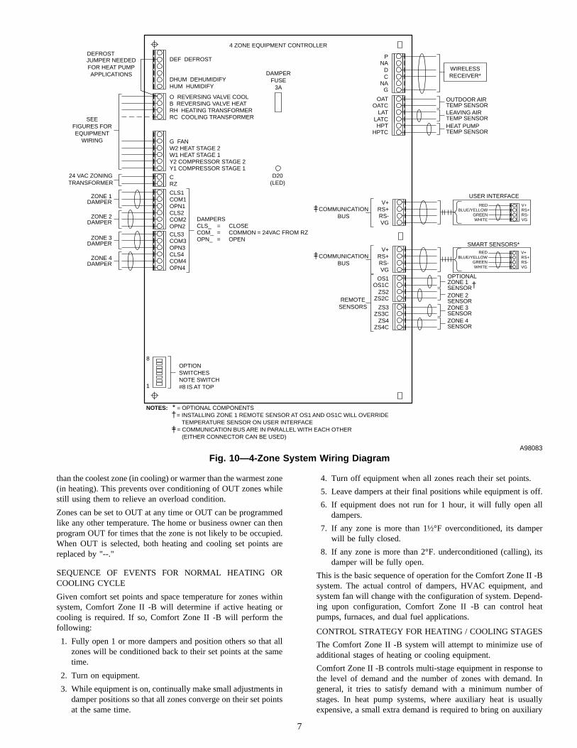
Fig. 10—4-Zone System Wiring DiagramA98083
O REVERSING VALVE COOLB REVERSING VALVE HEATRH HEATING TRANSFORMERRC COOLING TRANSFORMER
DEF DEFROST
DHUM DEHUMIDIFY
SEE FIGURES FOR EQUIPMENT
WIRING
24 VAC ZONING TRANSFORMER
CRZ
4 ZONE EQUIPMENT CONTROLLER
HUM HUMIDIFY
G FANW2 HEAT STAGE 2W1 HEAT STAGE 1Y2 COMPRESSOR STAGE 2Y1 COMPRESSOR STAGE 1
HPTC
LATLATCHPT
OATOATC
DAMPERS
8
1
CLS_COM_OPN_
===
CLOSECOMMON = 24VAC FROM RZOPEN
OUTDOOR AIR TEMP SENSORLEAVING AIR TEMP SENSORHEAT PUMP TEMP SENSOR
CLS3COM3OPN3CLS4COM4OPN4
ZONE 3 DAMPER
ZONE 4 DAMPER
CLS1COM1OPN1CLS2COM2OPN2
ZONE 1 DAMPER
ZONE 2 DAMPER
G
DC
NA
PNAJUMPER NEEDED
FOR HEAT PUMP APPLICATIONS DAMPER
FUSE 3A
OPTION SWITCHES NOTE SWITCH #8 IS AT TOP
D20 (LED)
USER INTERFACE
NOTES: * = OPTIONAL COMPONENTS = INSTALLING ZONE 1 REMOTE SENSOR AT OS1 AND OS1C WILL OVERRIDE TEMPERATURE SENSOR ON USER INTERFACE = COMMUNICATION BUS ARE IN PARALLEL WITH EACH OTHER (EITHER CONNECTOR CAN BE USED)
DEFROST
WIRELESS RECEIVER*
†
†
V+RS+RS-VG
REMOTE SENSORS
COMMUNICATION BUS
ZONE 3 SENSORZONE 4 SENSOR
OPTIONAL ZONE 1 SENSORZONE 2 SENSOR
V+
COMMUNICATION BUS
RS+RS-VG
OS1OS1C
ZS2ZS2C
ZS3ZS3C
ZS4ZS4C
V+RS+RS-VG
VG
V+
SMART SENSORS*
RS+RS-
WHITE
REDBLUE/YELLOW
GREEN
WHITE
REDBLUE/YELLOW
GREEN
†
†
†
7
heat. This acts to prevent the unnecessary use of auxiliary heat. Inaddition, when an outdoor sensor is attached, the system can be setto lock out auxiliary heat for outdoor temperatures above aninstaller selectable value. This will be covered under SystemConfiguration.
SYSTEM CONFIGURATIONComfort Zone II -B must be configured to match the type ofequipment connected to it. In addition, there are several choices ofconfiguration based on how the user wants the system to operate.Configuration is done in 2 parts. First is the setting of 8 DIPswitches on the Equipment Controller. The second is a group ofsoftware selections made via User Interface. Follow the sequencebelow for easy setup.
Configuration of the Equipment Controller is done first with thepower off. Then power is applied and the User Interface isconfigured with power on.
NOTE: A DIP switch module is oriented with switch 1 at thebottom and switch 8 at the top. Refer to Fig. 12 for switchorientation and labels.
Step 1—Equipment Controller Configuration
Located near bottom of Equipment Controller circuit board, thereis an 8 section DIP switch. The use of each switch is described
below. Using a pen or pencil, set each switch to its proper state.ON is to the left and is the factory setting. OFF is to the right. Fig.12 is a pictorial drawing of this selector switch.
Switch 1—Selects AC or HP.ON—Selects AC.OFF—Selects HP.
Switch 2—Selects single- or 2-speed compressor.ON—Selects single speed.OFF—Selects 2 speed.
Switch 3—Selects 3-stage electric heat. Equipment must includeFK or FV series fan coil with single-speed heat pump and properlyselected 3-stage electric heater.ON—Normal 1- or 2-stage electric heat.OFF—Special 3-stage electric heat.
Switch 4—Selects Smart Recovery in both heating and cooling.The system starts adjusting temperature 1-1/2-hours earlier thanselected recovery time so it will arrive at new temperature atselected time.ON—Smart recovery.OFF—Normal recovery.
Switch 5—Zone system address selection. When 2 zoning systemsare connected together, the second system should be set to OFF.
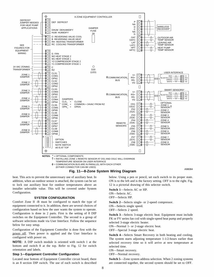
Fig. 11—8-Zone System Wiring DiagramA98084
O REVERSING VALVE COOLB REVERSING VALVE HEATRH HEATING TRANSFORMER
DHUM DEHUMIDIFY
DEF DEFROST
RC COOLING TRANSFORMERSEE FIGURES FOR EQUIPMENT
WIRING
24 VAC ZONING TRANSFORMER
CRZ
8 ZONE EQUIPMENT CONTROLLER
HUM HUMIDIFY
G FANW2 HEAT STAGE 2W1 HEAT STAGE 1Y2 COMPRESSOR STAGE 2Y1 COMPRESSOR STAGE 1
CLS7COM7OPN7CLS8
HPTC
LATLATCHPT
OATOATC
DAMPERS
8
1
CLS_COM_OPN_
===
CLOSECOMMON = 24VAC FROM RZOPEN
COM8OPN8
ZONE 7 DAMPER
ZONE 8 DAMPER
OUTDOOR AIR TEMP SENSORLEAVING AIR TEMP SENSORHEAT PUMP TEMP SENSOR
CLS5COM5OPN5CLS6COM6OPN6
ZONE 5 DAMPER
ZONE 6 DAMPER
CLS3COM3OPN3CLS4COM4OPN4
ZONE 3 DAMPER
ZONE 4 DAMPER
CLS1COM1OPN1CLS2COM2OPN2
ZONE 1 DAMPER
ZONE 2 DAMPER
JUMPER NEEDED FOR HEAT PUMP APPLICATIONS DAMPER
FUSE 3A
OPTION SWITCHES NOTE SWITCH #8 IS AT TOP
NA
DC
G
NAP
WIRELESS RECEIVER*
D20 (LED)
DEFROST
NOTES: * = OPTIONAL COMPONENTS = INSTALLING ZONE 1 REMOTE SENSOR AT OS1 AND OS1C WILL OVERRIDE TEMPERATURE SENSOR ON USER INTERFACE = COMMUNICATION BUS ARE IN PARALLEL WITH EACH OTHER (EITHER CONNECTOR CAN BE USED)
†
†
V+RS+RS-VG
REMOTE SENSORS
COMMUNICATION BUS
ZONE 3 SENSORZONE 4 SENSOR
OPTIONAL ZONE 1 SENSORZONE 2 SENSOR
V+
COMMUNICATION BUS
RS+RS-VG
OS1OS1C
ZS2ZS2C
ZS3ZS3C
ZS4ZS4C
ZONE 7 SENSORZONE 8 SENSOR
ZONE 5 SENSORZONE 6 SENSOR
ZS5ZS5C
ZS6ZS6C
ZS7ZS7C
ZS8ZS8C
V+
USER INTERFACE
RS+RS-VG
VG
V+
SMART SENSORS*
RS+RS-
WHITE
REDBLUE/YELLOW
GREEN
WHITE
REDBLUE/YELLOW
GREEN
†
†
†
8

ON—Normal single system (address = 01).OFF—Address selection for second zoning system.
Switch 6—Select installer test mode to assist in checking out thesystem. See Starting System.ON—Selects normal operation.OFF—Selects installer test mode.
Switch 7—Enables or prevents cooling when outdoor temperatureis below the value selected by software Configuration Option 6. Tolimit low temperature cooling, first set this switch to OFF and thenselect 55, 50, or 45 degrees farenheit with Configuration Option 6.Requires outdoor air temperature sensor.ON—Cooling enabled at all temperatures.OFF—Low temperature cooling disabled.
Switch 8—Dual fuel selection for systems with heat pump andfurnace.ON—Selects normal system.OFF—Selects dual fuel system.
All dual fuel installationsmust be equipped with a highpressure switch to turn off the compressor under a high indoorcoil pressure situation.The high pressure switch protects compressor and indoor coilfrom overpressure which would occur if a failure or wiringerror resulted in the heat pump and furnace operating at thesame time.Also, an outdoor temperature sensor must always be includedin dual fuel installations. If not, an E3 error message willappear. See Error Messages in the Troubleshooting section.
Step 2—User Interface Configuration
The User Interface is configured via a group of selections madethrough the keypad in a special configuration mode. Before theequipment is operated, the system must be properly configured.Make sure this step is not left out.
Before turning power on to the zoning system, disable the systemequipment itself by either turning off its main power or bytemporarily disconnecting its 24-vac power at the RC and RHterminals of the Equipment Controller. This will allow the zoningsystem only to operate. Go through the following steps with theequipment power off.
By this time 8 DIP switches on the Equipment Controller shouldbe properly set.
Turn on power to the zoning system by applying power to its24-vac transformer. When power is first applied to Comfort ZoneII -B the Equipment Controller immediately begins positioning alldampers to fully open by running each damper motor in the opendirection for 15 sec. This is done in succession, 2 zones at a time,starting with Zone 1. The time required will be 15 sec for each pairof zones. Remember that the system automatically determines thenumber of zones by detecting the presence of zone sensors.
At power up the User Interface displays all segments for a few sec.This is followed by the selected system type for an additional fewsec. The system type shows as follows:
1. AC—1-Speed Air Conditioner
2. HP—1-Speed Heat Pump
3. A2—2-Speed Air Conditioner
4. H2—2-Speed Heat Pump
5. HS—1 or 2-Speed Heat Pump with 3-Stage Auxiliary Heat
6. dF—Dual Fuel with 1-Speed Heat Pump
7. d2—Dual Fuel with 2-Speed Heat Pump
Power-on check of the User Interface itself can be done byseparating the User Interface from its backplate and then recon-necting it by attaching the 2 parts. This will allow observation ofthe User Interface at power up.
Several installer select options are set using the User Interfacekeypad.
These configuration options, like DIP switch settings, are intendedto be selected at installation and are normally not modified byhome or business owner. These options are not discussed in theOwner’s Guide and therefore must be made as part of theinstallation. A special procedure allows entry into configurationmode. Comfort Zone II -B will automatically exit this mode if nobutton is pressed for 3 minutes. While in the configuration mode,configuration choices can be made. In addition, LAT and HPTtemperatures as well as all damper positions can be viewed. A briefdescription of each is given below, followed by instructions onhow to make the selection.
Not all option numbers are used in this product. Options will onlyappear on the User Interface if they are used in the particularapplication, i.e., auxiliary heat lockout temperatures will appearwith heat pump selections, but not with AC/furnace selections.Option numbers between 1 and 29 are common to all wall mountedcontrols. Option numbers 30 and above are unique to zoningsystems.
TO ENTER THE CONFIGURATION MODE:
Press and hold FAN button for approximately 10 sec until roomtemperature and set point displays change to 2 numbers. You arenow in the configuration mode.
CONFIGURATION OPTIONS:
Option 2—Clean filter timer
Option 3—Fahrenheit or Celsius
Option 4—Fan (G) ON with W
Option 5—Variable speed ICM motor
Option 6—Low ambient cooling lockout temperature
Option 7—Variable speed superdehumidification
Option 8—Auxiliary heat lockout Temperature
Option 11—Dual fuel crossover temperature
Option 12—Defrost heat selection
Option 13—Zone temperature offset adjustment
Option 14—Heat/cool dead band adjustment
Fig. 12—DIP Switch SettingsA98183
NORM
NORM
NORM
NORM
SMART RECOVERY
1 SPD
AC
ON (CLOSED)
NORM
DISABLE LOW TEMP COOLING
INSTALLER TEST MODE
ADDRESS 11
3 STG HEAT
NORM
2 SPD
HP
OFF (OPEN)
DUAL FUEL
7
6
5
3
4
2
1
8
Switch factory default is closed.
NOTE:
9
→

Option 15—Enable AUTO mode
Option 16—Enable Comfort Heat mode
Option 18—Humidity offset adjustment
Option 19—Outdoor air temperature offset adjustment
Option 20—Enable programmable fan
Option 30—Display damper positions
Option 31—Display HPT temperature reading
Option 32—Display LAT temperature reading
Option 33—Select LAT shutdown temperature
Option 34—User Interface address
Option 35—Disable zoning
Option 36—Select HPT or LAT sensor to monitor cooling
Option 37—Ignore LAT/HPT safeties
Option 38—Select auto changeover time(1,9,10,17,21-29 are not applicable)
NOTE: If END button is pressed or if no button is pressed for 3minutes, Comfort Zone II -B will exit configuration mode andreturn to normal operation. To re-enter configuration mode, FANbutton must be pressed and held for 10 sec again.
While in configuration mode, the large display shows the selectionwhich has been made and the smaller display (COOL set pointdisplay) shows current option number. One of these will beflashing.
The up and down buttons are used both to move between availableoptions and to make selection for each option. When optionnumber (small display) is flashing, the up and down buttons adjustit, moving between available option numbers. After desired optionnumber has been selected, press SET TIME/TEMP button. Thelarge display will now flash, indicating that the up and downbuttons now control available choices within that option. Eachpress of the SET TIME/TEMP button switches between availableoption (small display) and available selections within each option(large display).
Available options and available selections for each are describedbelow.
OPTION 2—CLEAN FILTER TIMER
Select hours of blower operation (heating, cooling, or fan) beforeCLEAN FILTER icon is displayed. With OFF selected, icon willnever come on, disabling this feature. Time selection can be from400 to 3600 hours by selecting numbers 1 through 9. (Time is400X number selected.) Factory default is 2 (800 hours). Recom-mended selections are: disposable filter—400 to 800 hours, mediafilter—1200 to 1600 hours, or electronic air cleaner—1600 to 2400hours of blower operation.
AVAILABLE SELECTIONS:Use UP and DOWN buttons to alternate between OF (off) and 1 to9 in steps of 1.
OPTION 3—FAHRENHEIT OR CELSIUS
Select between Fahrenheit or Celsius operation. Factory default isFahrenheit.
AVAILABLE SELECTIONS:Use UP or DOWN buttons to alternate between F or C.
OPTION 4—FAN (G) ON WITH W
This selection determines whether the G (fan) output is to be ONor OFF when any W (furnace or strip heat) output is ON. Mostfurnaces and fan coils manage their own blowers and do notrequire a separate G signal. For these applications, select OFF.Some auxiliary heaters require a separate G signal to turn on theblower. In this case, select ON. Factory default is OFF.
AVAILABLE SELECTIONS:Use UP or DOWN buttons to alternate between OF (off) and ON.
OPTION 5—VARIABLE SPEED (ICM) BLOWER
If the furnace or fan coil contains a variable speed ICM blower, setthis option ON. For normal (PSC) blowers, set to OF (off). Thisselection enables the system to use Comfort Heat features avail-able only with the ICM blower. Factory default is OF (off).
AVAILABLE SELECTIONS: Use UP or DOWN buttons toalternate between OF (off) and ON.
OPTION 6—COOLING LOCKOUT TEMPERATURE
This option allows selection of the outdoor temperature belowwhich cooling is not allowed. DIP switch 7 still enables or disablesthis function, but this option allows setting its temperature. If DIPswitch 7 is ON (cooling is enabled at all outdoor temperatures),Option 6 will display OF and cannot be changed. If DIP switch 7is OFF (cooling can be disabled below a selected temperature),Option 6 will allow the selection of 45, 50 or 55 degrees F. For allresidential equipment, select 55 degrees. For light commercialequipment, select minimum outdoor cooling temperature fromequipment instructions. Factory default is 55.
AVAILABLE SELECTIONS:Use the UP and DOWN buttons to move between 45, 50 and 55.
OPTION 7—VARIABLE SPEED SUPER DEHUMIDIFICA-TION
This function only operates with selected Comfort Heat compat-ible furnaces and fan coils. Refer to furnace or fan coil instruc-tions. Option 5 must be set to ON for this option to appear. Whenthere is a ’cool to dehumidify’ demand (a dehumidification demandbut no cooling demand), the blower CFM is reduced to a minimumto obtain maximum dehumidification. While a ’cool to dehumidify’demand exists, the equipment is cycled ON for 10 min. and thenOFF for 10 min. The reduced blower CFM is produced by a Ysignal without a G signal. ON enables this function. Factorydefault is OF.
AVAILABLE SELECTIONS:Use UP or DOWN buttons to alternate between OF (off) and ON.
OPTION 8—AUXILIARY HEAT LOCKOUT TEMPERATURESELECTION
This option is available only with heat pump and dual fuel systems.In heat pump systems, auxiliary heat is prevented from coming onwhile outdoor temperature is above the selected value. In dual fuelsystems, the furnace is prevented from operating while outdoortemperature is above the selected value. This temperature must beset higher or equal to that of option 11. (See option 11 below.)Outdoor temperatures of 5, 10, 15, 20, 25, 30, 35, 40, 45, 50, or55°F or OF (off) may be selected. If OF (off) is selected, outdoortemperature does not affect system operation. Factory default isOF (off).
AVAILABLE SELECTIONS:Use UP and DOWN buttons to move between 5 and 55 or OF (off)in steps of 5.
OPTION 11—DUAL FUEL CROSSOVER TEMPERATURESELECTION
This option is only available with dual fuel systems. While outdoortemperature is below the selected value, only the furnace is usedfor heating. This option must be set lower than or equal to that ofoption 8. (See option 8 above.) If the temperature selections ofoption 8 and 11 are set to the same value, a dual fuel system willuse the heat pump only above this temperature and the furnaceonly below this temperature. If the selections are different, therange between the 2 selections will use the heat pump as the firststage and the furnace as the second stage. Once the furnace comes
10

on, it will remain on until the demand is satisfied. The followingcycle will start with the heat pump. Outdoor temperatures of 5, 10,15, 20, 25, 30, 35, 40, 45, 50, or 55°F or OF (off) may be selected.If OF (off) is selected, outdoor temperature does not affect systemoperation. Factory default is OF (off).
AVAILABLE SELECTIONS:Use UP and DOWN buttons to move between 5 and 55 or OF (off)in steps of 5.
OPTION 12—DEFROST HEAT SELECTION
A new feature that allows heat pump defrost cycles to always runto completion and includes a software selectable amount of auxheat during defrost. The equipment controller now senses 24vac onthe O line (which it did not put there) during a defrost. In responseto this, it maintains the Y signal as long as the O signal exists,assuring defrost runs to completion. It now can also turn on W1and/or W2 during defrost to control the amount of defrost heat.Option 12 makes this selection. Select O for no heat, 1 for W1 on,2 for W1 and W2 on, and 3 for W2 only on. This last selection isonly available if 3-stage heat is selected by turning DIP switch 3off. When 1, 2 or 3 are selected, no wire should be connectedbetween the W terminals of the heat pump and the indoor unit.Factory default is 0.
AVAILABLE SELECTIONS:Use UP and DOWN buttons to move between 0, 1, 2, or 3.
OPTION 13—ZONE TEMPERATURE OFFSET ADJUSTMENT
Each zone temperature reading can be independently offset by upto plus or minus 5 degrees F. While Option 13 is selected, theNEXT ZONE button moves between zones and the UP andDOWN buttons select an offset value between -5 and +5 degreesF in 1 degree F steps. The offset number is added to the actual zonetemperature to produce the offset zone temperature, which isdisplayed and used by the system. Factory default value is 0.
AVAILABLE SELECTIONS:Use UP and DOWN buttons to move between -5 and 5 in steps of1.
OPTION 14—HEAT/COOL DEADBAND ADJUSTMENT
The minimum allowable difference between the heat and cool setpoints can be selected to any value between 0 and 6 degrees F. Thefactory default value is 2. Higher numbers provide less precisetemperature control but save energy. Lower numbers providecomfort with more energy use. If the deadband is set to less than2, the mode is set to auto changeover, and the auto changeovertimer is small (see Option #38), continuous alternating heat andcool cycles may occur. This wastes energy, but may be desired toreduce humidity. When used with the ’COOL TO DEHUMIDIFY’selection, effective cooling with reheat can occur.
AVAILABLE SELECTIONS:Use UP and DOWN buttons to move between 0 and 6 in steps of1.
OPTION 15—ENABLE AUTO MODE
In some applications, auto changeover from heat to cool may notbe desired. Option 15 selects ON or OF (off) for auto changeover.When OF, the AUTO mode icon never appears, disabling theAUTO mode. Factory default is ON.
AVAILABLE SELECTIONS:Use UP or DOWN buttons to alternate between OF (off) and ON.
OPTION 16—ENABLE SUPER COMFORT HEAT MODE
The Comfort Heat operation is the same as that for the Thermi-distat. This selection is only available if heat pump (DIP switch 1)and variable speed blower (Option 5) selections are already made.While heat pump is heating, the blower speed is reduced (by
removal of the G signal) for outdoor temperatures between 12 and40 degrees F., providing warmer leaving air temperatures. For heatpumps with electric aux heat and outdoor temperatures below 12degrees F., any heat call is accompanied by a W1 signal, bringingon the first stage of aux heat to again increase leaving airtemperature. Factory default is OF (off).
AVAILABLE SELECTIONS:Use UP or DOWN buttons to alternate between OF (off) and ON.
OPTION 18—HUMIDITY OFFSET ADJUSTMENT
Like the zone temperature offset, the humidity reading can beoffset by plus or minus 10% in 1% steps. This offset adjusts thehumidity sensor output and therefore affects both humidify anddehumidify performance. Factory default is 0.
AVAILABLE SELECTIONS:Use UP and DOWN buttons to move between -10 and 10 in stepsof 1.
OPTION 19—OUTDOOR TEMPERATURE OFFSET ADJUST-MENT
Use this option to offset the outdoor temperature reading within arange of plus or minus 5 degrees F. Factory default is 0.
AVAILABLE SELECTIONS:Use up and down buttons to move between -5 and 5 in steps of 1.
OPTION 20—ENABLE PROGRAMMABLE FAN
This option allows the blower to operate continuously (fan = ON)during the day and automatically (fan = AUTO) at night. Whenenabled, if the fan mode is set to ON, it will operate in AUTOduring the Zone 1 SLEEP period. Factory default is OF (off).
OTHER AVAILABLE SELECTIONS:Still using UP or DOWN buttons to alternate between OF (off) andON.
Options 30, 31, and 32 allow direct viewing of the temperatures ofthe HPT and LAT sensors and the positions of all zone dampers.They are useful for setup and troubleshooting. When these optionsare selected, the temperatures or positions appear on the largedisplay. All other system operation is unchanged. When Option 30is selected, use the NEXT ZONE button on the User Interface tomove between zones. Closed position is 0. Fully open is 15.Temperature above 100°F are shown as the amount above 100.
OPTION 30—DISPLAY DAMPER POSITIONS
Previously, Options 21 through 28 were used to view Zone 1through Zone 8 damper positions. Now, Option 30 is selected forall damper positions and the NEXT ZONE button is used to movebetween the zones. This saves option numbers and makes scanningdamper positions easier.
OPTION 31—DISPLAY HPT TEMPERATURE READING
OPTION 32—DISPLAY LAT TEMPERATURE READING
OPTION 33—SELECT LAT SHUTDOWN TEMPERATURE
This option selects maximum allowable LAT in furnace and fancoil auxiliary heat installations. Equipment will be turned off if itsLAT exceeds selected value. Values are 15, 20, 25, 30, 35, 40, 45,50, 55, 60, 65, 70, or 75 corresponding to temperatures of 115° to175°F. As LAT nears selected limit, actions are taken by thesystem to try to reduce the LAT. These include staging downmulti-stage equipment and limited conditioning of OUT zones.
When the LAT temperature approaches its limit, OUT zonedampers progressively open, allowing more airflow into the ductsystem. The temperatures of the OUT zones are also monitored. Asany OUT zone approaches the temperature of the most conditionedzone, its damper closes again, preventing the OUT zone frombeing over conditioned. If OUT zones are not available and LATtemperature cannot be maintained at a safe value, the system will
11
shut down the equipment when the LAT temperature reaches itslimit. If the equipment is shut down by a LAT or HPT limit trip,the small ’equipment on’ triangle on the display will be flashing toindicate this condition. Continuous fan is energized during aLAT/HPT Limit Trip. This is true for both heating and cooling. Aswith earlier Comfort Zone systems, temperature set here wastemperature where actions werestarted. Shutdown temperaturewas 20°F higher than selected temperature. Therefore a setting of155°F on Comfort Zone I is equivalent to 175°F on Comfort ZoneII -B.
Heat pump temperature limit for shut down is fixed at 115°F andcooling LAT temperature limit for shut down is fixed at 40°F(down from Comfort Zone I which was 45°F.)
Fan coils vary greatly in their LAT (leaving air temperature)because of variations in the size of their heaters and their air flow.This makes proper selection of LAT limits difficult. A value of 50(150 °F limit) should be adequate. After the system is in operation,LAT can be monitored via User Interface (configuration option 31or 32) to check actual operating temperature. For furnaces select avalue of 75°F plus the rated maximum temperature rise from thefurnace nameplate. Factory default is 50 (or 150°F).
AVAILABLE SELECTIONS:Use UP and DOWN buttons to move between 15 and 75 in stepsof 5.
OPTION 34—USER INTERFACE ADDRESS
When 2 Comfort Zone II -B systems are connected together on thesame bus, each must have a different address. Address 01 is usedfor single systems. Address 11 is selected for second UserInterface when present. Factory default is 01.
AVAILABLE SELECTIONS:Use UP or Down buttons to alternate between 01 and 11.
OPTION 35—DISABLE ZONING
When this option is selected, all dampers go fully open and zone1 sensor (normally User Interface itself) becomes the sensor for theentire home or business. In effect, the zoning system disappearsand is replaced by a single thermostat. In this mode, the ZONE Xwhere X is the zone number is not displayed. Factory default is OF(off), zoning enabled. This option is used to check out the systemequipment. The User Interface acts as normal thermostat.
AVAILABLE SELECTIONS:Use UP or DOWN buttons to alternate between OF (off) and ON.
OPTION 36—SELECT HPT OR LAT SENSOR TO MONITORCOOLING
Previously, the LAT sensor, located in the leaving air path, wasalways used to monitor cooling leaving air temperature. There aresome applications where the HPT sensor, located just downstreamof the coil, is better suited to measure the cooling leaving airtemperature. This option allows the installer to make this selection.
AVAILABLE SELECTIONS:Use UP or DOWN buttons to alternate between LA (use LATsensor) and HP (use HPT sensor).
OPTION 37—LAT/HPT SAFETIES
Leaving this selection ON can cause permanent damage toHVAC equipment
This option, when ON, tells the system to ignore the LAT and HPTtemperature information. It shouldonly be used for troubleshoot-ing and to allow temporary operation with a failed or missingsensor until the sensor can be replaced. Factory default is OF (off).
AVAILABLE SELECTIONS:Use UP or DOWN buttons to alternate between OF (off) and ON.
NOTE: ON is for temporary use only.
OPTION 38—SELECT AUTO CHANGEOVER TIME
This option selects a 5 to 30minute time delay between heat andcool while in auto changeover mode. System must have no demandin current mode for selected time before changeover betweenheating and cooling is allowed. Factory default is 30 minutes.
AVAILABLE SELECTIONS:Use UP and DOWN buttons to move between 5 and 30 in steps of5.
SYSTEM STARTUP AND CHECKOUT
Comfort Zone II -B is designed with built-in checkout capabilityfor both the equipment and the zoning system. Use the sequencebelow for trouble free setup. When it is time to start up system forthe first time, you may want to check out the zoning system firstand the equipment second or to reverse the process, checkingequipment first and zoning system second. Either way is accept-able.
The following sequence checks out zoning system first. If youwish to check equipment first, proceed to Step 4 below. Then, afterequipment is operating properly, return to Steps 1, 2, and 3 tocheck out zoning system.
Step 1—Enable Installer Setup Mode
Select installer setup mode at the Equipment Controller by movingDIP switch No. 6 to the OFF position. (See Fig. 12.) This may bedone with power on or off.This mode is indicated by InStappearing in the User Interface clock display. In this modeseveral special features are available to assist in the setup/checkoutprocess:
a. When a zone is selected with the NEXT ZONE button, itsdamper opens fully and all other dampers close.
b. The selected zone’s temperature appears on the largedisplay.
c. The FAN button turns the blower ON or OFF.
d. The MODE button operates HEAT, COOL, or EHEAT for2 minutes and then returns automatically to OFF.Nodemand from the zones is needed to bring on theequipment in installer setup mode.
Step 2—Check Damper and Sensor Operation
At the User Interface, set the mode to OFF using the MODEButton to make sure cooling or heating outputs are not turned on.Use the FAN button to turn on the blower by selecting ON (notAUTO) under the fan icon. This will start the blower (if its supplypower is on). Use the NEXT ZONE button to select ZONE 1 abovethe large display. This will open Zone 1 fully and close all otherzones. It will take the system 15 sec for each zone to complete thisprocess.
You may now physically observe the dampers to verify theirpositions are correct (and check for air blowing out all Zone 1registers only). The large display reads the temperature in Zone 1.Use this opportunity to verify the Zone 1 sensor is properlyconnected and is located in Zone 1 by breathing on the Zone 1sensor and observing the temperature change. Remember, theZone 1 sensor is normally inside the User Interface but a remotesensor may be used.
Use the NEXT ZONE button to select Zone 2 and repeat the aboveprocess. Continue through all zones. When finished, you will haveverified that all the dampers and zone sensors are properlyconnected and working.
12

Step 3—Quick Check of Equipment Operation
Either this or the next step (Step 4) may be used for initial startup.This check runs equipment for only 2 minutes on each stage and isadequate to see that each stage comes on properly. For temperaturerise, charge levels, etc. use the longer check, or disable zoningfeature.
Be sure installer setup is still selected (Equipment Controller DIPswitch No. 6 is OFF).
At User Interface, select HEAT mode. The first stage of heat willcome on immediately (no temperature demand is needed). For aheat pump, this will be Y1 and G. For an air conditioning system,this will be W1. The first stage will remain on for 2 minutes. Thenthe second stage of heat will come on for 2 minutes. This will beY1, Y2, and G for a heat pump, or W1 and W2 for an airconditioning system. At the end of 4 minutes, equipment will turnoff and mode will automatically return to OFF. If mode is set toOFF at any time during 4 minutes, equipment will turn offimmediately. Note that single stage system (heat or cool) willremain on for full 4 minutes because there will be no connectionto Y2 or W2.
The same applies to COOL. When selected, cooling will come onimmediately with no need for temperature demand. First stage willbe Y1, G (and O if a heat pump) and will run for 2 minutes. ThenY1, Y2, G (and O if a heat pump) will come on for next 2 minutes.At the end of 4 minutes equipment will turn off and mode willreturn to OFF.
In a heat pump system, EHEAT may also be selected at UserInterface. This will turn on W1 only for first 2 minutes and thenW1 and W2 for the second 2 minutes. The compressor will not run.As above, equipment may be turned off at any time during the 4minutes by setting mode to OFF.
For all operation in this installer setup mode, no demand is needed,no compressor timeguard exists, and no temperatures are moni-tored. This means there is no protection for equipment, and this isthe reason that operation is limited to 4 minutes.
When leaving this step, be sure to return installer setup switch(Equipment Controller DIP switch No. 6) to ON position. This willenable normal operation.
When any output is turned on, a red LED on the EquipmentController board adjacent to the output’s connection terminal isalso turned on. This can be used at any time to monitor the state ofthe Equipment Controller outputs, even if the equipment is not yetconnected or powered. Remember, the DEHUM output is a reverselogic relay. This means its LED will be ON while there is nodehumidify demand. See dehumidification section.
Step 4—Longer Check of Equipment Operation
When more detailed tests need to be made on equipment, the 2 or4 minute run time provided in Step 3 may not be adequate. Byselecting disable zoning mode (turn Option No.35 to ON underUser Interface configuration), system operates like a standardthermostat system. All dampers go fully open, and the zone whichis displayed on User Interface provides set points. This zone’stemperature is the only controlled temperature. Equipment willoperate as if it were being controlled by a single thermostat in thedisplayed zone. Use this option to check out equipment as youwould with a normal thermostat. When finished, be sure to returnto the configuration mode and turn Option No.35 OFF to enablenormal zoning operation.
FINAL INSTALLATION SETTINGSHumidification Description
If a humidifier is included in the system, Comfort Zone II -B candirectly control it. If a conventional humidity control exists, itshould be removed and the zoning system used in its place.
Comfort Zone II -B provides superior convenience and features.When installing a 24-vac humidifier, connect it directly to theHUM terminal on the Equipment Controller and C terminal ofindoor equipment.
DO NOT connect furnace HUM terminal directly to Equip-ment Controller HUM terminal. This will bypass furnacesafety controls. See Low Voltage Wiring Diagrams and notesfor proper connection.
A humidity sensor is built into the User Interface to monitor andcontrol relative humidity. The HUM output will control anyhumidifier with a 24-vac input. A humidify set point can be set toany value between 10 percent and 45 percent or can be turned off.When the humidity drops 2 percent below the set point, the HUMoutput is activated to turn on a humidifier. When the humidity rises2 percent above the set point, the HUM output will turn off.
When an outdoor air temperature sensor is attached, an automatichumidity level adjustment can be selected. This selection providesa 1 percent reduction in the humidity set point for every 2 degreesreduction in outdoor temperature. The set point can be changed atany time, and it will then automatically adjust itself up and downwith changes in outdoor temperature. In no case will the set pointgo above 45 percent or below 10 percent. This feature is to preventsweating of windows in very cold weather while allowing higherhumidity levels in warmer weather.
Another selection involves the interlocking of the HUM output toheating or fan operation. The HUM output can be set to come ononly when there is a humidity demand and any heat output is on(heat pump, furnace, or auxiliary heat). A second setting allows theHUM output and the blower to turn on when there is humiditydemand. This selection allows humidification with the fan whenthere is a no heat call. In no case will the HUM output be onwithout either heat or fan.
It may be advisable to configure the humidity control as part of theinstallation process. Following is a brief description of the hu-midify setup process. It is also covered in the Owner’s Manual.
There are 5 selections for humidification in the heating mode:
1. Normal Humidify
2. Fan Humidify
3. Auto Humidify
4. Auto and Fan Humidify
5. OFF
Humidification Setup
To make a humidification selection or change the humidity (hu) setpoint, a 2-button keypad press is required. Press SET TIME/TEMPand FAN buttons simultaneously (indicated on keypad by the RHsymbol) to enter humidity mode. Either hu (humidify) or dh(dehumidify) will appear in the clock display. Use the SETTIME/TEMP button to select hu. The actual humidity now appearsin the large display, the humidify set point appears in the heat setpoint display, and the small triangle icon below the set point isturned on when the humidify output is active. The UP and DOWNbuttons now adjust the humidify set point and the MODE buttonscrolls through the 5 available humidification modes. These aredescribed below. Table 1 shows the display indication for each ofthe 5 humidification modes.
1. Normal Humidify Mode—This is the factory default. InNormal Humidify, the humidifier will be on only if there is ahumidify demand and any heating equipment is on. This willinclude furnace, heat pump, or auxiliary heat. In heat pump
13

applications, this is an improvement over using an externalhumidistat, which only supplies humidity when auxiliary heatis on.
2. Fan Humidify Mode—This configuration allows a humiditydemand to turn on the fan and the humidifier together, even ifthere is no heat demand. It is particularly useful when afurnace is oversized, resulting in short heating cycles. It allowsthe humidifier to run longer, supplying more humidity to thehome. Note that fan hours will increase, using more electric-ity. Also, the humidifier delivers less moisture to cooler airthan it does to heated air.
3. Auto Humidify—This feature is designed to eliminate theproblem of sweating windows in very cold weather. Whenselected, the set point is reduced by 1 percent for every dropof 2°F. in outdoor temperatures between 50°F. and 0°F. Theset point may be changed at any time. It will continue to trackoutdoor temperature from the new set point and the currentoutdoor temperature. The adjusted set point range is stilllimited between 10% and 45% relative humidity. To use thisfeature, the outdoor temperature sensorMUST be attached. Ifnot, an E3 error message will be displayed.
4. Auto and Fan Humidify—The two choices of Auto Humidifynd Fan Humidify are combined in this selection.
5. Humidify Off—The humidify function can be turned offcompletely. This does not require changing existing set points.
To exit humidity setup mode, press END button, or if no buttonsare pressed for 3 minutes, the User Interface will save and exit thismode, returning to normal operation.
Dehumidification Description
Comfort Zone II -B contains a rich set of capabilities for theenhancement and control of dehumidification, particularly whenused with a variable speed (ICM) blower. Depending on the typeof equipment used, compressor speed, blower speed, set pointadjustment, and equipment cycling are modified to provide addeddehumidification.
A dehumidification set point(separate from the humidification setpoint) can be set to a value between 50 percent and 90 percenthumidity or can be turned off. When the humidity rises above thisset point by 2 percent, the dehumidify output is turned off. Whenthe humidity falls to 2 percent below this set point, the dehumidifyoutput turns on, supplying 24vac at its output. This output can beused to control any 24-vac device which decreases humidity whenits control signal is removed.
When a variable speed blower with a dehumidify input is usedwith the system, the dehumidify output can be connected to itsdehumidify input. This connection provides reduced cooling airflow while dehumidification is needed yielding better moistureremoval from cooling air.
If the system has a 2-speed compressor (as selected by EquipmentController DIP switch No. 2) and a PSC blower (as selected byUser Interface Option No. 5), a dehumidify demand will make
compressor operate at high speed only for any cooling demand.High speed provides better water removal than low speed when a2-speed compressor is used with PSC blower.
Another selection provides humidity control by operating thecooling system when cooling is not required. If the humidity risesabove the dehumidification set point, a special dehumidificationroutine is executed. As long as zone temperatures are not morethan 3°F below their cooling set points, a dehumidify demand willturn on the cooling equipment but will limit its ON time to no morethan 10 minutes at a time.
Finally, OUT zones are used to their maximum capability. Whena zone is set to OUT it can be used to help remove humidity bycooling it as much as possible. When there is a dehumidify demandand a zone set to OUT, its damper is fully opened, and it can becooled down to as low as 70°F. If it reaches 70°F its damper willclose.
When all zones are set to OUT the house is in vacation mode. Thecooling equipment will come on either to maintain the housebelow 85°F or to maintain the dehumidify set point by cooling thehouse down to as low as 70°F. This is a valuable feature forunoccupied homes in hot and damp climates.
Dehumidification Setup
IMPORTANT: It may be advisable to configure the dehumidifycontrol as part of the system installation process. Following is abrief description of the dehumidify setup process. It is also coveredmore thoroughly in the Owner’s Manual.
There are 4 selections for dehumidification in the cooling mode:
1. Normal Dehumidify
2. Cool to Dehumidify
3. Vacation Dehumidify
4. OFF
To make a dehumidification selection or change the dehumidify(dh) set point, a 2-button keypad press is required. Press SETTIME/TEMP and FAN buttons simultaneously (indicated onkeypad by the RH symbol) to enter humidity mode. Either hu(humidify) or dh (dehumidify) will appear on the clock display.Use the SET TIME/TEMP button to select dh (dehumidify). Theactual humidity now appears in the large display, the dehumidifyset point appears in the cool set point display, and the smalltriangle icon below the set point is turned on when the dehumidifyoutput is active. The UP and DOWN buttons now adjust thedehumidify set point. The MODE button scrolls through theavailable dehumidification modes. These are described below.Table 2 shows the display indication for each of the dehumidifi-cation modes below. Note special instructions for the VacationDehumidify mode.
1. Dehumidify Off—This is used to disable dehumidification. Itis indicated on the display by OF in the dehumidify set pointlocation.
2. Normal Dehumidify Mode—this is the factory default. Whennormal dehumidify is selected, the compressor will not turn onwithout a cooling demand. If a dehumidify demand existswhile cooling, the dehumidify output will be active (24vacremoved from DHUM terminal of Equipment Controller). Avariable speed blower will respond by reducing its airflow by20%. If the fan is set for continuous operation (fan mode =ON) the fan will turn off for 5 minutes at the end of eachcooling cycle to allow condensate draining and preventre-evaporation. For this to work properly, the blower off delayof the equipment itself must be defeated. In this mode, thedehumidify set point appears and can be set to any valuebetween 50 and 90% relative humidity.
Table 1—Displays of Available Humidify Modes
SELECTION MODE DISPLAY FAN DISPLAY HUMIDIFY DISPLAY
Normal Humidity Blank Blank HSP Value
Fan Humidity Blank Fan HSP Value
Auto Humidity Auto Blank HSP Value
Auto and Fan Auto Fan HSP Value
Humidify Off Blank Blank OF
HSP = Humidity Set Point
OF = Off
14
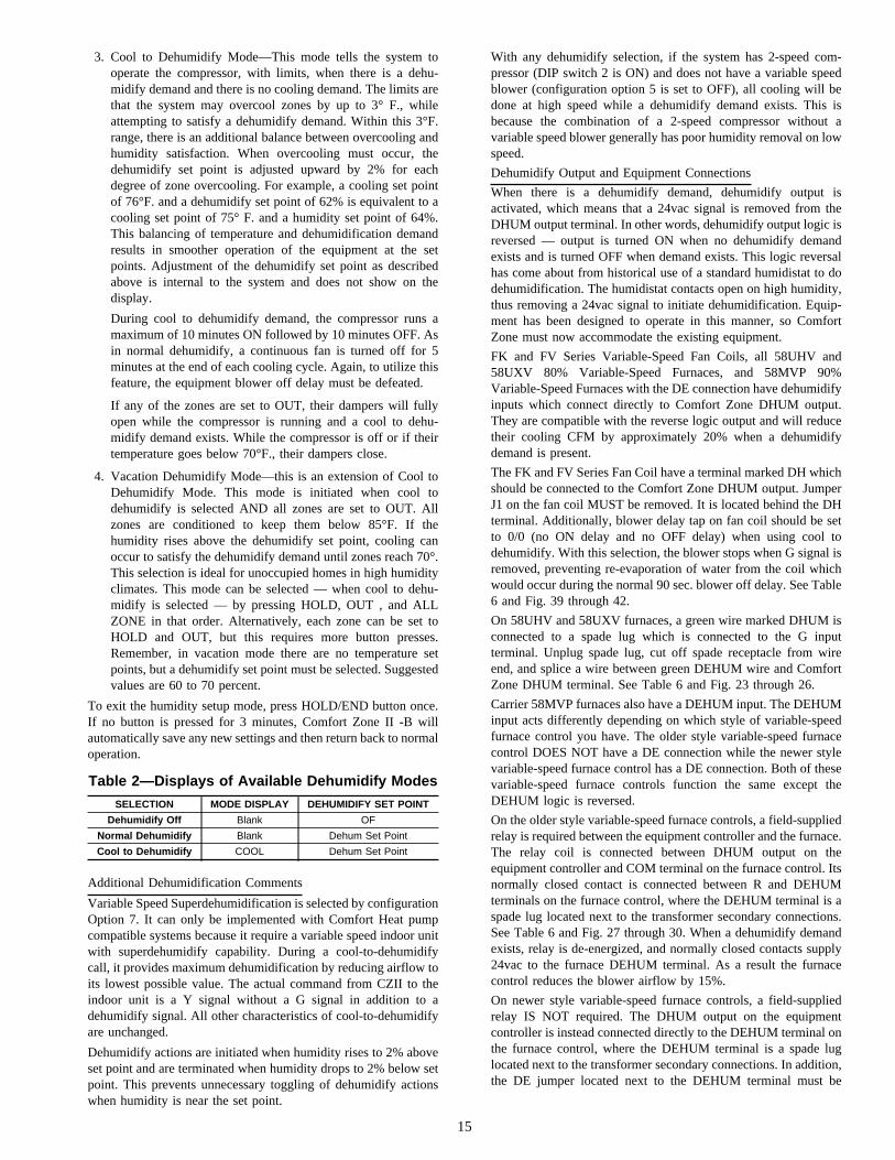
3. Cool to Dehumidify Mode—This mode tells the system tooperate the compressor, with limits, when there is a dehu-midify demand and there is no cooling demand. The limits arethat the system may overcool zones by up to 3° F., whileattempting to satisfy a dehumidify demand. Within this 3°F.range, there is an additional balance between overcooling andhumidity satisfaction. When overcooling must occur, thedehumidify set point is adjusted upward by 2% for eachdegree of zone overcooling. For example, a cooling set pointof 76°F. and a dehumidify set point of 62% is equivalent to acooling set point of 75° F. and a humidity set point of 64%.This balancing of temperature and dehumidification demandresults in smoother operation of the equipment at the setpoints. Adjustment of the dehumidify set point as describedabove is internal to the system and does not show on thedisplay.
During cool to dehumidify demand, the compressor runs amaximum of 10 minutes ON followed by 10 minutes OFF. Asin normal dehumidify, a continuous fan is turned off for 5minutes at the end of each cooling cycle. Again, to utilize thisfeature, the equipment blower off delay must be defeated.
If any of the zones are set to OUT, their dampers will fullyopen while the compressor is running and a cool to dehu-midify demand exists. While the compressor is off or if theirtemperature goes below 70°F., their dampers close.
4. Vacation Dehumidify Mode—this is an extension of Cool toDehumidify Mode. This mode is initiated when cool todehumidify is selected AND all zones are set to OUT. Allzones are conditioned to keep them below 85°F. If thehumidity rises above the dehumidify set point, cooling canoccur to satisfy the dehumidify demand until zones reach 70°.This selection is ideal for unoccupied homes in high humidityclimates. This mode can be selected — when cool to dehu-midify is selected — by pressing HOLD, OUT , and ALLZONE in that order. Alternatively, each zone can be set toHOLD and OUT, but this requires more button presses.Remember, in vacation mode there are no temperature setpoints, but a dehumidify set point must be selected. Suggestedvalues are 60 to 70 percent.
To exit the humidity setup mode, press HOLD/END button once.If no button is pressed for 3 minutes, Comfort Zone II -B willautomatically save any new settings and then return back to normaloperation.
Additional Dehumidification Comments
Variable Speed Superdehumidification is selected by configurationOption 7. It can only be implemented with Comfort Heat pumpcompatible systems because it require a variable speed indoor unitwith superdehumidify capability. During a cool-to-dehumidifycall, it provides maximum dehumidification by reducing airflow toits lowest possible value. The actual command from CZII to theindoor unit is a Y signal without a G signal in addition to adehumidify signal. All other characteristics of cool-to-dehumidifyare unchanged.
Dehumidify actions are initiated when humidity rises to 2% aboveset point and are terminated when humidity drops to 2% below setpoint. This prevents unnecessary toggling of dehumidify actionswhen humidity is near the set point.
With any dehumidify selection, if the system has 2-speed com-pressor (DIP switch 2 is ON) and does not have a variable speedblower (configuration option 5 is set to OFF), all cooling will bedone at high speed while a dehumidify demand exists. This isbecause the combination of a 2-speed compressor without avariable speed blower generally has poor humidity removal on lowspeed.
Dehumidify Output and Equipment Connections
When there is a dehumidify demand, dehumidify output isactivated, which means that a 24vac signal is removed from theDHUM output terminal. In other words, dehumidify output logic isreversed — output is turned ON when no dehumidify demandexists and is turned OFF when demand exists. This logic reversalhas come about from historical use of a standard humidistat to dodehumidification. The humidistat contacts open on high humidity,thus removing a 24vac signal to initiate dehumidification. Equip-ment has been designed to operate in this manner, so ComfortZone must now accommodate the existing equipment.
FK and FV Series Variable-Speed Fan Coils, all 58UHV and58UXV 80% Variable-Speed Furnaces, and 58MVP 90%Variable-Speed Furnaces with the DE connection have dehumidifyinputs which connect directly to Comfort Zone DHUM output.They are compatible with the reverse logic output and will reducetheir cooling CFM by approximately 20% when a dehumidifydemand is present.
The FK and FV Series Fan Coil have a terminal marked DH whichshould be connected to the Comfort Zone DHUM output. JumperJ1 on the fan coil MUST be removed. It is located behind the DHterminal. Additionally, blower delay tap on fan coil should be setto 0/0 (no ON delay and no OFF delay) when using cool todehumidify. With this selection, the blower stops when G signal isremoved, preventing re-evaporation of water from the coil whichwould occur during the normal 90 sec. blower off delay. See Table6 and Fig. 39 through 42.
On 58UHV and 58UXV furnaces, a green wire marked DHUM isconnected to a spade lug which is connected to the G inputterminal. Unplug spade lug, cut off spade receptacle from wireend, and splice a wire between green DEHUM wire and ComfortZone DHUM terminal. See Table 6 and Fig. 23 through 26.
Carrier 58MVP furnaces also have a DEHUM input. The DEHUMinput acts differently depending on which style of variable-speedfurnace control you have. The older style variable-speed furnacecontrol DOES NOT have a DE connection while the newer stylevariable-speed furnace control has a DE connection. Both of thesevariable-speed furnace controls function the same except theDEHUM logic is reversed.
On the older style variable-speed furnace controls, a field-suppliedrelay is required between the equipment controller and the furnace.The relay coil is connected between DHUM output on theequipment controller and COM terminal on the furnace control. Itsnormally closed contact is connected between R and DEHUMterminals on the furnace control, where the DEHUM terminal is aspade lug located next to the transformer secondary connections.See Table 6 and Fig. 27 through 30. When a dehumidify demandexists, relay is de-energized, and normally closed contacts supply24vac to the furnace DEHUM terminal. As a result the furnacecontrol reduces the blower airflow by 15%.
On newer style variable-speed furnace controls, a field-suppliedrelay IS NOT required. The DHUM output on the equipmentcontroller is instead connected directly to the DEHUM terminal onthe furnace control, where the DEHUM terminal is a spade luglocated next to the transformer secondary connections. In addition,the DE jumper located next to the DEHUM terminal must be
Table 2—Displays of Available Dehumidify Modes
SELECTION MODE DISPLAY DEHUMIDIFY SET POINT
Dehumidify Off Blank OF
Normal Dehumidify Blank Dehum Set Point
Cool to Dehumidify COOL Dehum Set Point
15

removed to enable the DEHUM input. See Table 6 and Fig. 31through 34. When a dehumidify demand exists, the furnace controlreduces the blower airflow by 21%.
OPERATIONAL INFORMATIONFive-minute Compressor Timeguard
This timer prevents the compressor from starting unless it has beenoff for at least 5 minutes. It can be defeated for 1 cycle bysimultaneously pressing the FAN mode button and the UP button.It is not active in the installer setup mode.
Fifteen-minute Cycle Timer
This timer prevents the start of the next cycle until at least 15minutes after the start of the present cycle. Its job is to assure thatequipment is not cycled more than 4 times per hour (or 1 cycleevery 15 minutes). It is defeated for 1 cycle when the set point ismanually changed to provide fast response to set point change. Itcan also be defeated for 1 cycle by simultaneously pressing theFAN mode and UP buttons.
Staging Timer
In multistage heating or cooling this timer prevents any higherstage from coming on until the previous stage has been on for 10minutes. The timer is extended to 15 minutes for heat pumpauxiliary heat and dual fuel furnace operation.
Minimum On Time
When a cooling or heating stage is turned on, it will remain on forat least 3 minutes. These timers are canceled when set points arechanged.
Heat/Cool Set Point Difference
The deadband between heating and cooling set points is selectedby configuration Option 14. This deadband is maintained byallowing one set point to ’push’ the other to maintain the requiredminimum difference. This is true in programming of schedules andadjustment of set points in operation.
Auto Changeover
When the auto changeover mode is selected, a change from heat tocool or cool to heat cannot occur until a demand exists in the newmode and no demand has appeared in the old mode for the amountof time selected by configuration Option 38. Note that this meansthat for changeover to occur, the old mode must be and remainsatisfied for the selected changeover time. Use the 30 minutesetting for installations which should change modes only twice perday. The 5 minute setting will allow simultaneous heating andcooling demands to be serviced.
Emergency Heat Mode
When system is configured for a heat pump and EHEAT mode isselected, Y outputs are disabled and W outputs only are used forheat.
Power-On Check
When power is first applied to the system the large displayindicates the equipment type selected by DIP switches as follows:
1. AC—1-Speed Air Conditioner
2. HP—1-Speed Heat Pump
3. A2—2-Speed Air Conditioner
4. H2—2-Speed Heat Pump
5. HS—1 or 2-Speed Heat Pump with 3-Stage Auxiliary Heat
6. dF—Dual Fuel with 1-Speed Heat Pump
7. d2—Dual Fuel with 2-Speed Heat Pump
Other Messages
Small Arrow—A small arrow is located to the left of HEAT andCOOL icons which are located under the two set point displays.
These indicate when cooling or heating equipment is actuallyoperating. When arrows flash, equipment is waiting to come on butis being held off by compressor timeguard, cycle timer, or becauseLAT or HPT has exceeded its limits and temporarily turnedequipment off. When the humidity screen is displayed, these samearrows show the state of the humidify and dehumidify outputs.
Multiple Sensors in a Single Zone
In applications where a zone is large or contains several rooms, itmay be desirable to have several sensors which are connected toread their average temperature. This may be done using 4 or 9 (or16 or 25) sensors connected in series/parallel.
Initial Power-On Performance
When power is applied to system all dampers are fully opened. Asoperation progresses, the system "learns" optimum damper posi-tions needed to maintain set points in all zones. This learningprocess may require up to 2 hours of operation. Allow the systemtime to complete its learning.
Overshoot Control
If for any reason a zone is over-conditioned by more than 1.5degrees and the equipment is still operating, that zone’s damperwill fully close until the over-conditioning is less than 1.5 degrees.
Undershoot Control
If, for any reason, a zone is underconditioned, by more than 2°F.,that zone’s damper will be fully opened until the undercondition-ing is less than 2°F.
Temperature Balancing
Under heavy load conditions when the HVAC system does nothave sufficient capacity to maintain all set points, the system doesnot automatically open all dampers fully. It continues to controldampers to keep temperature error in each zone the same as allothers.
Ventilator Mode
An automatic ventilation mode is provided by keeping all dampersat their final position while equipment is off. If the fan is left ON,more air is supplied to zones which required most conditioning.Those which required none will have their dampers closed. If 1hour passes and there is no call for conditioning, all dampers openfully. In addition, if the mode selection is set to OFF and the fanselection is set to ON, all dampers will immediately open.
Outputs vs. Stages
Table 3 lists the active outputs for each stage of each possiblesystem configuration. G is not shown.
For 1-stage furnaces and auxiliary heat connect to W1 and leaveW2 open.
For single speed compressors, connect to Y1 and leave Y2 open.
QUICK STARTThe quick start procedure outlined below will allow you to useyour zoning system before you learn all the details of systemoperation. This setup may be done by the installer. For the bestcomfort and energy-saving results, we recommend that you readthrough the Owner’s Guide and set up the system to match theend-user’s schedule and comfort requirements.
To begin, locate the User Interface and follow the steps outlinedbelow: (See Fig. 14.)
Set current day and time:
1. Press NEXT DAY button until current day of the week isshown.
2. Press SET TIME/TEMP button until the TIME icon flashes.
3. Press UP or DOWN buttons until the desired time is shown,making sure that the AM or PM time is correct.
16

4. Press HOLD/END key to exit.
Select system Mode:
1. Press MODE button to select HEAT or COOL.
2. Press HOLD/END button to turn on HOLD icon.
3. Press UP or DOWN button until the desired temperature isdisplayed.
4. Press ALL ZONE button to turn on ALL ZONE icon if thisdesired temperature is needed for every zone. With ALLZONE selected, all zones are controlled to a single set point,providing even temperatures in all zones. Otherwise pressNEXT ZONE button, and repeat HOLD function in selectingthe desired temperature for each zone.
QUICK PROGRAMMING OF COMFORT SCHEDULES
The following is a brief overview of how to access and programschedules in your new zoning system. We highly recommend thatyou read and follow the programming information provided in theOwner’s Guide for detail step-by-step instructions.
Before proceeding, set the correct Time and Day at the UserInterface (see above Quick Start).
However, if you followed the above Quick Start procedure inselecting the system mode, you will need to reverse the ALLZONE and/or HOLD functions before proceeding. Simply pressALL ZONE and/or HOLD button to remove these icons from thedisplay. (See Fig. 14.) Make sure HOLD is removed from eachzone.
During the programming process, you will have access to 4program time periods, e.g., WAKE, DAY, EVE, and SLEEP. Youwill be able to select program start times and the heat/cool setpoints for each time period and zone. Use the Keypad to enter andmove around inside the program. Use the temperature UP andDOWN buttons to adjust the start times and to raise and lower setpoints. When inside the program, the blinking icon indicates that asetting may now be changed.
1. Decide on a program schedule that you desire. Table 4 is anexample of what already exists in the User Interface as theEnergy Star recommended settings.
2. To begin programming, press PROGRAM button.
3. Press NEXT ZONE button until ZONE 1 appears on the LCDdisplay.
4. Press NEXT DAY button until Monday (Mo) is displayed.
5. Press NEXT PERIOD button until the WAKE period isdisplayed.
6. Press SET TIME/TEMP button until the TIME icon isflashing.
7. Start programming ZONE 1 beginning with the WAKE starttime. Press the UP or DOWN button until the desired startingtime is displayed, make sure that the AM is correct.
8. Press SET TIME/TEMP button until the HEAT icon isflashing. Press UP or DOWN button until the desired heatingtemperature for that period is displayed.
9. If that zone is going to be unoccupied, press OUT button. Formore information regarding the Out feature, read the follow-ing section pertaining to Hold, Off, Out, and All Zone.
10. Press SET TIME/TEMP button until the COOL icon isflashing. Press UP or DOWN button until the desired coolingtemperature for that period is displayed. You have nowprogrammed the time and desired heating and cooling tem-peratures for Monday, ZONE 1, in the WAKE time period.
11. Press NEXT PERIOD button to change from WAKE to theDAY period. Repeat steps 6 through 11 for programming thetime and desired heating and cooling temperatures for Mon-day, ZONE 1, in the DAY time period. Use NEXT PERIODbutton again to select EVE and SLEEP, and repeat procedure.
12. After Monday ZONE 1 is completely programmed, you mayselect NEXT DAY and advance to Tuesday. You can nowpress COPY DAY button and copy the program schedule fromMonday into Tuesday. This can be repeated as needed for eachremaining day in the week. However, if copying the previousday is not desired, you may individually program each dayusing the NEXT DAY button and repeating steps 6 through12. Press HOLD/END button to exit programming mode.
You may also use the button pair marked COPY ZONE (COPYPERIOD and COPY DAY buttons simultaneously) to copy a fullweek from 1 zone to the next. First use NEXT ZONE to select thenew zone, and then press COPY ZONE pair to copy the entireweek from the original zone into the new zone.
NOTE: Other ways to program comfort schedules with theirfunction keys can be found in the Owner’s Manual.
HOLD, OFF, OUT, AND ALL ZONE
The following will provide detailed information regarding HOLD,OFF, OUT, and ALL ZONE functions: (See Fig. 14.)
HOLD FUNCTION
At the User Interface or Smart Sensor(s):
Pressing HOLD button activates and deactivates HOLD functionfor a single zone.
When HOLD function is active, HOLD icon is displayed, and thecurrent set points will be used until the user cancels the HOLDfunction. The HOLD function prevents the set points from
Table 3—Outputs vs. Stages
SYSTEM TYPE COOL 2 COOL 1 HEAT 1 HEAT 2 HEAT 3 HEAT 4 HEAT 5
1-Speed AC N/A Y1 W1 W1,W2 N/A N/A N/A
2-Speed AC Y1,Y2 Y1 W1 W1,W2 N/A N/A N/A
1-Speed HP N/A Y1,O Y1 Y1,W1 Y1,W1,W2 N/A N/A
with 3-Stage Heat N/A Y1,O Y1 Y1,W1 Y1,W2 Y1,W1,W2 N/A
2-Speed HP Y1,Y2,O Y1,O Y1 Y1,Y2 Y1,Y2,W1 Y1,Y2,W1,W2 N/A
with 3-Stage Heat Y1,Y2,O Y1,O Y1 Y1,Y2 Y1,Y2,W1 Y1,Y2,W2 Y1,Y2,W1,W2
1-Speed Dual Fuel N/A Y1,O Y1 W1 W1,W2 N/A N/A
2-Speed Dual Fuel Y1,Y2,O Y1,O Y1 Y1,Y2 W1 W1,W2 N/A
Table 4—User Interface Settings
TIME COOL HEATWAKE 6:00 AM 78 68DAY 8:00 AM 85 60EVE 5:00 PM 78 68
SLEEP 10:00 PM 82 60
17

SMART SENSOR OPERATIONNOTE: Refer to Smart Sensor Installation and Start-Up Instructions for proper installation and set-up procedure.
The Smart Sensor can control the setting of zone temperature, OUT, HOLD, or OFF. It can also display outdoor temperature and indoorhumidity.
Hold Out Set Temp
Fig. 13—Comfort Zone II — Smart SensorA97186
CHANGING SET POINT
1. The current temperature in that zone will be displayed in the LCD.
2. Press UP or DOWN button once to display set point for that zone. The LCD will display the currentmode of operation, either heat or cool.
3. Press UP or DOWN button again as needed until new set point is shown.
4. Press SET TEMP button to change temperature between COOL set point and HEAT set point.
5. Pressing HOLD button will hold set point setting indefinitely. Pressing HOLD button again removesHOLD function.
6. Pressing OUT button will program zone as being unoccupied. Pressing OUT button again changeszone to occupied. When a zone is set to OUT, desired temperature will be displayed as dashes whenUP and DOWN buttons are pressed.
VIEWING OUTDOOR TEMPERATURE AND INDOOR HUMIDITY
1. Pressing both UP and DOWN buttons simultaneously will display outdoor temperature, if this featureis included, and indoor humidity. Outdoor temperature will be displayed first for 5 sec, followed byhumidity for 5 sec. Smart Sensor will then return to normal. The humidity value will be humidity levelas measured at user interface.
NOTE: If All Zone feature has been enabled from user interface, you will not be able to override settingsat Smart Sensor location. The desired temperature will be displayed as dashes when UP and DOWNbuttons are pressed. You must first remove All Zone function by pressing ALL ZONE button on userinterface.
A Smart Sensor does not remove or transfer features from User Interface. It only provides a location withinzone where access is provided to some of User Interface features. Any input that can be provided at SmartSensor can also be provided at User Interface.
OUT
COOLDESIRED TEMP
OUT
Smart Sensor display with ALL ZONE enabled
18
→

changing according to the program schedule. Cancelling theHOLD function changes the set points to whatever is in theprogram schedule for that period of the day.
OFF FUNCTION
At the User Interface:
Scrolling the heat set point past its lower limit (40°F), or the coolset point past its upper limit (90°F) activates the OFF function fora single zone. When a zone is set to OFF, the set points aredisplayed as "OF" and the damper is closed. No conditioning willbe provided to that zone.
To cancel OFF, press UP button to change the heat set point, orDOWN button to change the cool set point.
When a zone is set to OFF, the HOLD icon will turn on indicatingthat OFF is a permanent override. The HOLD icon cannot beturned off by pressing the HOLD button. However, if HOLD wasturned on prior to turning OFF that zone, then HOLD status willremain after OFF is cancelled.
The ALL ZONE function cannot be activated from a zone that isset to OFF.
All zonescannotbe set to OFF. If end-user attempts to do this, theUser Interface software will prevent the last zone from going toOFF.
At the Smart Sensor(s):
Same as above; scrolling the heat set point past its lower limit(40°F), or the cool set point past its upper limit (90°F) activates theOFF function for a single zone. When a zone is set to OFF, the setpoints are displayed as "OF" and the damper is closed. Noconditioning will be provided to that zone.
OUT FUNCTION
At the User Interface:
Pressing OUT button activates and deactivates OUT function for asingle zone. When OUT function is active, OUT icon is displayed.This function programs the zone as being unoccupied.
When OUT function is active, the zone has no set points. The zonetemperature will be kept within the 60-85°F range and if necessary,the zone will be used as a "dump" zone to relieve LAT problemsor to assist with dehumidification. The set points are displayed as"--", and pressing UP and DOWN buttons will have no effect.
To cancel OUT function, press OUT button and OUT icon willturn off. Pressing OUT button is a temporary override that will becancelled at the next programmed schedule time unless the HOLDfunction is also active.
The OUT function is also a programmable option. You canprogram the OUT function in the program schedules.
If a zone is set to OFF, the OUT button will have no effect. OFFmust be cancelled before OUT can become active.
At the Smart Sensor(s):
Same as the above; pressing OUT button will program the zone asbeing unoccupied. Pressing OUT button again changes the zone tooccupied. When a zone is set to OUT, the desired temperature willbe displayed as "--" when UP and DOWN buttons are pushed.
ALL ZONE
At the User Interface:
Pressing ALL ZONE button activates and deactivates ALL ZONEfunction. When ALL ZONE function is active, ALL icon isdisplayed.
This function allows the entire house to be controlled to the setpoints and program schedule of a single zone.
The zone that is displayed when ALL ZONE button is pressed isthe controlling zone. Its set points will be displayed normally. Ifthe NEXT ZONE button is pressed while ALL ZONE is active, theroom temperature for each zone will be displayed, but the setpoints for the non-controlling zones will be displayed as "--".
This function is not available if the zoning has been turned offthrough software configuration.
This function is not available if the controlling zone is set to OFF.
At the Smart Sensor(s):
The ALL ZONE function cannot be changed from the SmartSensor, but if the function is active, and the Smart Sensor is in azone other than the controlling zone, the set point display willshow "--".
If the Smart Sensor is in the controlling zone, then it cannot bescrolled to OFF.
TROUBLESHOOTINGERROR MESSAGES
Several error messages are provided. They appear on the largedisplay and alternate with the normal room temperature data at a 2sec rate. These are:
1. E1—COMMUNICATION FAILURE. An E1 will be dis-played if the User Interface cannot communicate with theEquipment Controller. Check and make sure V+, Vg, RS+,and RS- are wired correctly between the User Interface andEquipment Controller. This error message may sometimestake up to 30 seconds before it is displayed. After the problemhas been fixed, cycle power to insure that all errors havecleared.
2. E2—LAT or HPT SENSOR FAILURE. An E2 will bedisplayed if the temperature sensor is open, or if it is readingbelow -40°F or above 230°F. This error can be temporarilyoverridden for troubleshooting purposes only by turning onconfiguration option No. 37 in the User Interface. This willignore the LAT/HPT sensors while you replace the sensorsand/or investigate the problem.Disabling this feature shouldonly be temporary. Failure to properly install the LAT/HPTsensors can cause permanent damage to the HVAC equip-ment, as well as lose other features that the zoning system canprovide, e.g., OUT zone, etc.
3. E3—OUTDOOR AIR TEMPERATURE SENSOR FAIL-URE. An E3 will be displayed if the outdoor air temperaturesensor is open, or if it is reading below -40°F or above 180°F.This error will also occur if the following features are activeand the Equipment Controller cannot detect the outdoor airtemperature sensor:
Fig. 14—Comfort Zone II -B KeypadA98134
19

(1.) Auxiliary Heat Lockout (System is configured as aheat pump and configuration Option No. 8 is active).
(2.) Dual Fuel Setup (DIP switch No. 8 OFF. System isconfigured as a heat pump with dual fuel).
(3.) Cooling Lockout Below 55°F (DIP switch No. 7 OFF.System is configured to disable cooling when outdoortemperature is below value selected by Option 6).
(4.) Automatic Humidify Feature (User Interface is setupfor auto-humidify in heating mode).
(5.) Comfort Heat Feature (System is configured withComfort Heat configuration Option 16 ON).
4. E4—NONVOLATILE MEMORY FAILURE. An E4 will bedisplayed if the configuration and program schedules cannotbe read. This is usually the result of a microprocessor failure.If cycling power does not reset this error, the User Interfacemust be replaced.
5. E5—HUMIDITY SENSOR FAILURE. If the humidity sensorhas failed, an E5 error message will be displayed.
6. E6—DEFROST LOCKED. An E6 will be displayed if thedefrost cycle is in process longer than 10 minutes. The modewill automatically change to the EHEAT mode. Cyclingpower will reset error, however, outdoor unit should bechecked to determine if defrost is operating properly.
7. FF—DAMPER FUSE BLOWN. An FF will be displayed ifthe fuse is open or missing. Remove plastic cover on Equip-ment Controller to locate and replace fuse.
8. "--" (2 dashes)—TEMPERATURE SENSOR FAILURE. Twodashes "--" will be displayed if a zone temperature sensor hasfailed or is out of range. The User Interface and Remote RoomSensors are considered failed if the temperature reading isoutside the -40°F to 140°F range. A Smart Sensor is consid-ered failed if the temperature is outside the 32°F to 140°Frange. See Table 5 to determine the temperature/ohm relation-ship for a Remote Sensor. Do not confuse dashes in thedisplay ("--") for a zone that is set to OUT or ALL ZONE.
Other Helpful Hints
Read and understand "System Startup and Checkout" to reviewInstaller Test Setup Mode and check the equipment operation. Thisis a good place to start in evaluating any problems associated withthe zoning system or the system equipment.
Temperature/Ohm Relationship
Table 5 shows a temperature/ohm relationship to help aid introubleshooting the Comfort Zone II -B System. This table willevaluate the Remote Sensor, LAT, and HPT sensor operation. Usea digital multimeter to perform the following:
To verify if a sensor is good, disconnect both leads from I/O boardand measure resistance through the sensor. Match ohm reading tothe table and compare temperature reading on table to ambienttemperature surrounding sensor (accuracy should be within a fewpercent).
e.g. If 10.72k ohms are measured, this equals approximately 74°F.To verify if equipment controller is functioning normally, reattachsensor to equipment controller and set meter to 5vdc. Measurevoltage across terminal connections with sensor attached. A typicalvoltage of approximately 2.5vdc will indicate equipment controlleris functioning correctly.
Table 5—Temperature/Ohm Relationship
TEMP F° OHMS
30 34,480
32 32,630
34 30,760
36 29,220
38 27,470
40 26,020
42 24,680
44 23,320
46 22,070
48 20,910
50 19,830
52 18,820
54 17,870
56 16,920
58 16,160
60 15,260
62 14,530
64 13,790
66 13,090
68 12,480
70 11,860
72 11,270
74 10,750
76 10,250
78 9,750
80 9,300
82 8,840
84 8,432
86 8,042
88 7,668
90 7,310
92 6,993
94 6,661
96 6,368
98 6,085
100 5,811
102 5,571
104 5,313
106 5,088
108 4,869
110 4,660
112 4,450
114 4,268
116 4,019
118 3,918
120 3,750
20

Table 6—Wiring Diagram Reference Chart
EQUIPMENTSELECTION
1-SPEEDAC
2-SPEEDAC
1-SPEEDHP
2-SPEEDHP
1-StageFurnace Fig. 15 Fig. 16 Fig. 17 Fig. 18
2-StageFurnace Fig. 19 Fig. 20 Fig. 21 Fig. 22
Variable-Speed Non-Condensing Furnace Fig. 23 Fig. 24 Fig. 25 Fig. 26Variable-Speed 2-Stage Condensing Furnace
Variable-W/O DE Connection Fig. 27 Fig. 28 Fig. 29 Fig. 30
Variable-Speed 2-Stage Condensing Furnacewith DE Connection 31 32 33 34
Typical Fan Coil Fig. 35 Fig. 36 Fig. 37 Fig. 38FK4C Fan Coil Fig. 39 Fig. 40 Fig. 41 Fig. 42
Fig. 17—Single-Stage Furnacewith 1-Speed Heat Pump (Dual Fuel)
A98091
C
O
R
W2
C
R
Y
W
G
Y
SINGLE-STAGEFURNACE
SINGLE-SPEED HEAT
PUMPEQUIPMENT
CONTROLLER
OB
RHRC
DEF
DHUMHUM
W2W1
G
Y2Y1
N/AHEAT STAGE 2
FAN
N/ACOOL/HEAT STAGE 1
N/ARVS COOLING
DEFROST
N/AHUMIDIFY
24 VAC HOT
See notes 1, 2, 3, 6, 10, 11, and 19
HUMIDIFIER(24 VAC)
Fig. 15—1-Stage Furnace with 1-Speed AirConditioner
A98089
CC
R
Y
W
G
Y
N/A
SINGLE-STAGEFURNACE
SINGLE-SPEED AIR
CONDITIONER
EQUIPMENTCONTROLLER
N/A24 VAC HOT
N/A
N/AHUMIDIFY
OB
RHRC
W2W1
G
Y2Y1
DEF
DHUMHUM
HUMIDIFIER(24 VAC)
N/AHEAT STAGE 1
FAN
N/ACOOL STAGE 1
See note 19
Fig. 18—1-Stage Furnace with2-Speed Heat Pump (Dual Fuel)
A98092
TWO-SPEED HEAT
PUMP
C
O
R
W2
Y2
W3
C
R
Y1
W
G
Y
OB
RH
SINGLE-STAGEFURNACE
EQUIPMENTCONTROLLER
RC
DEF
DHUMHUM
W2W1
G
Y2Y1
N/A
N/A
N/A
HEAT STAGE 3
FAN
DEFROST
HUMIDIFY
RVS COOLING
24 VAC HOT
COOL/HEAT STAGE 2COOL/HEAT STAGE 1
See notes 1, 2, 3, 4, 6, 7, 8, 9, 10, 11, and 19
HUMIDIFIER(24 VAC)
Fig. 16—1-Stage Furnace with2-Speed Air Conditioner
A98090
CC
R
Y1
Y2
W
G
Y
SINGLE-STAGEFURNACE
TWO-SPEED AIR
CONDITIONEREQUIPMENT
CONTROLLER
OB
RHRC
W2W1
G
Y2Y1
N/AHEAT STAGE 1
FAN
N/A24 VAC HOT
N/A
COOL STAGE 2COOL STAGE 1
See notes 4 and 19
R
N/A
N/AHUMIDIFY
DEF
DHUMHUM
HUMIDIFIER(24 VAC)
21

Fig. 21—2-Stage Furnacewith 1-Single Speed Heat Pump (Dual Fuel)
A98095
C
O
R
W2
C
R
G
Y
W/W1
W2
Y/Y2
OB
RH
DEF
DHUMHUM
RVS COOLING
TWO-STAGE
FURNACE
SINGLE-SPEED HEAT
PUMP
EQUIPMENTCONTROLLER
N/A24 VAC HOT
DEFROST
N/AHUMIDIFY
RC
W2W1
G
Y2Y1
HEAT STAGE 3HEAT STAGE 2
FAN
N/ACOOL/HEAT STAGE 1
HUMIDIFIER(24 VAC)
See notes 1, 2, 3, 6, 10, 11, 12, and 19
Fig. 19—2-Stage Furnacewith 1-Speed Air Conditioner
A98093
CC
R
Y
W/W1
G
W2
Y/Y2
OB
RH
N/A
TWO-STAGE FURNACE
SINGLE-SPEED AIR
CONDITIONEREQUIPMENT
CONTROLLER
N/A24 VAC HOT
RC
W2W1
G
Y2Y1
HEAT STAGE 2HEAT STAGE 1
FAN
N/ACOOL STAGE 1
See notes 12 and 19
N/A
N/AHUMIDIFY
DEF
DHUMHUM
HUMIDIFIER(24 VAC)
Fig. 22—2-Stage Furnacewith 2-Speed Heat Pump (Dual Fuel)
A98096
W/W1
W2
Y/Y2
TWO-SPEED HEAT
PUMP
C
O
R
W2
Y2
W3
C
R
Y1
G
OB
RHRC
DEF
W2W1
G
Y2Y1
HEAT STAGE 4HEAT STAGE 3
FAN
COOL/HEAT STAGE 2COOL/HEAT STAGE 1
See notes 1, 2, 3, 4, 6, 7, 8, 9, 10, 11, 12, and 19
TWO-STAGEFURNACE
EQUIPMENTCONTROLLER
RVS COOLING
DEFROST
HUMIDIFY
N/A24 VAC HOT
DHUMHUM
HUMIDIFIER(24 VAC)
Fig. 20—2-Stage Furnacewith 2-Speed Air Conditioner
A98094
CC
R
Y1
W/W1
G
W2
Y/Y2
OB
RH
N/A
TWO-STAGE FURNACE
TWO-SPEEDAIR CONDITIONER
EQUIPMENTCONTROLLER
N/A24 VAC HOT
RC
W2W1
G
Y2Y1
HEAT STAGE 2HEAT STAGE 1
FAN
COOL STAGE 2COOL STAGE 1
See notes 4, 12, and 19
N/A
N/AHUMIDIFY
DEF
DHUMHUM
HUMIDIFIER(24 VAC)
R
Y2
22

Fig. 25—Variable-Speed Non-Condensing Furnacewith 1-Speed Heat Pump (Dual Fuel)
A98099
CC
R
Y
W/W1
G
W2
Y/Y2
OB
RH
RVS COOLING
VSP FURNACEBOARD
SINGLE-SPEED HEAT
PUMPEQUIPMENT
CONTROLLER
N/A24 VAC HOT
RC
W2W1
G
Y2Y1
HEAT STAGE 3HEAT STAGE 2
FAN
N/ACOOL/HEAT STAGE 1
See notes 1, 2, 3, 6, 10, 11, 12, 15, 16, and 19
DEFROST
DEHUMIDIFYHUMIDIFY
DEF
DHUMHUM
HUMIDIFIER(24 VAC)
R
O
W2
HUM
DHUMPL9-10
O
Y1 AIRFLOW SELECTBOARD
Fig. 23—Variable-Speed Non-Condensing Furnacewith 1-Speed Air Conditioner
A98097
CC
R
Y
W/W1
G
W2
Y/Y2
OB
RH
N/A
VSP FURNACEBOARD
SINGLE-SPEED AIR
CONDITIONER
EQUIPMENTCONTROLLER
N/A24 VAC HOT
RC
W2W1
G
Y2Y1
HEAT STAGE 2HEAT STAGE 1
FAN
N/ACOOL STAGE 1
See notes 12, 15, 16, and 19
N/A
DEHUMIDIFYHUMIDIFY
DEF
DHUMHUM
HUMIDIFIER(24 VAC)
HUM
DHUM
PL9-10
O
Y1 AIRFLOW SELECTBOARD
Fig. 26—Variable-Speed Non-Condensing Furnacewith 2-Speed Heat Pump (Dual Fuel)
A98100
CC
R
Y2
W/W1
G
W2
Y/Y2
OB
RH
RVS COOLING
VSP FURNACEBOARD
TWO-SPEED HEAT
PUMPEQUIPMENT
CONTROLLER
N/A24 VAC HOT
RC
W2W1
G
Y2Y1
HEAT STAGE 3HEAT STAGE 2
FAN
COOL/HEAT STAGE 2COOL/HEAT STAGE 1
See notes 1, 2, 3, 4, 6, 7, 8, 9, 10, 11, 12, 15, 16, and 19
DEFROST
DEHUMIDIFYHUMIDIFY
DEF
DHUMHUM
HUMIDIFIER(24 VAC)
R
W3
O
W2
Y1
HUM
DHUMPL9-10
O
Y1 AIRFLOW SELECTBOARD
Fig. 24—Variable-Speed Non-Condensing Furnacewith 2-Speed Air Conditioner
A98098
CC
R
Y2
W/W1
G
W2
Y/Y2
OB
RH
N/A
VSP FURNACEBOARD
TWO-SPEED AIR
CONDITIONEREQUIPMENT
CONTROLLER
N/A24 VAC HOT
RC
W2W1
G
Y2Y1
HEAT STAGE 2HEAT STAGE 1
FAN
COOL STAGE 2COOL STAGE 1
See notes 4, 12, 15, 16, and 19
N/A
DEHUMIDIFYHUMIDIFY
DEF
DHUMHUM
HUMIDIFIER(24 VAC)
R
Y1
HUM
DHUMPL9-10
O
Y1 AIRFLOW SELECTBOARD
23

Fig. 29—Variable-Speed 2-Stage CondensingFurnace — W/O DE Connection -
with 1-Speed Heat Pump (Dual Fuel)
A98103
CC
R
W2W/W1
G
W2
Y/Y2
OB
RH
RVS COOLING
VSP SPEEDFURNACE
SINGLE-SPEEDHEAT PUMP
EQUIPMENTCONTROLLER
N/A24 VAC HOT
RC
W2W1
G
Y2Y1
HEAT STAGE 3HEAT STAGE 2
FAN
N/ACOOL/HEAT STAGE 1
See notes 1, 2, 3, 6, 10, 11, 12, 15, 17, and 19
DEFROST
DEHUMIDIFYHUMIDIFY
DEF
DHUMHUM
HUMIDIFIER(24 VAC)
R
Y
HUM
DEHUM O
Fig. 27—Variable-Speed 2-Stage CondensingFurnace — W/O DE Connection -
with 1-Speed Air Conditioner
A98101
CC
R
Y
W/W1
G
W2
Y/Y2
OB
RH
N/A
VSP CONDENSINGFURNACE
SINGLE-SPEED AIR
CONDITIONEREQUIPMENT
CONTROLLER
N/A24 VAC HOT
RC
W2W1
G
Y2Y1
HEAT STAGE 2HEAT STAGE 1
FAN
N/ACOOL STAGE 1
See notes 12, 15, 17, and 19
N/A
DEHUMIDIFYHUMIDIFY
DEF
DHUMHUM
HUMIDIFIER(24 VAC)
HUM
DEHUM
Fig. 30—Variable-Speed 2-Stage CondensingFurnace — W/O DE Connection -
with 2-Speed Heat Pump
A98104
CC
R
W2
W/W1
G
W2
Y/Y2
OB
RH
RVS COOLING
VSP SPEEDFURNACE
TWO-SPEEDHEAT PUMP
EQUIPMENTCONTROLLER
N/A24 VAC HOT
RC
W2W1
G
Y2Y1
HEAT STAGE 4HEAT STAGE 3
FAN
COOL/HEAT STAGE 2COOL/HEAT STAGE 1
See notes 1, 2, 3, 4, 6, 7, 8, 9, 10, 11, 12, 15, 17, and 19
DEFROST
DEHUMIDIFYHUMIDIFY
DEF
DHUMHUM
HUMIDIFIER(24 VAC)
R
W3
Y1
Y2
HUM
DEHUM O
Fig. 28—Variable-Speed 2-Stage CondensingFurnace — W/O DE Connection -
with 2-Speed Air Conditioner
A98102
CC
R
Y2W/W1
G
W2
Y/Y2
OB
RH
N/A
VSP CONDENSINGFURNACE
TWO-SPEED AIR
CONDITIONEREQUIPMENT
CONTROLLER
N/A24 VAC HOT
RC
W2W1
G
Y2Y1
HEAT STAGE 2HEAT STAGE 1
FAN
COOL STAGE 2COOL STAGE 1
See notes 4, 12, 15, 17, and 19
N/A
DEHUMIDIFYHUMIDIFY
DEF
DHUMHUM
HUMIDIFIER(24 VAC)
R
Y1
HUM
DEHUM
24

Fig. 33—Variable-Speed 2-Stage CondensingFurnace — With DE Connection —
With 1-Speed Heat Pump (Dual Fuel)
A99374
CC
R
W2W/W1
G
W2
Y/Y2
OB
RH
RVS COOLING
VSP SPEEDFURNACE
SINGLE-SPEEDHEAT PUMP
EQUIPMENTCONTROLLER
N/A24 VAC HOT
RC
W2W1
G
Y2Y1
HEAT STAGE 3HEAT STAGE 2
FAN
N/ACOOL/HEAT STAGE 1
See notes 1, 2, 3, 6, 10, 11, 12, 15, 18, and 19
DEFROST
DEHUMIDIFYHUMIDIFY
DEF
DHUMHUM
HUMIDIFIER(24 VAC)
R
Y
HUM
ODEHUM
DE
Fig. 31—Variable-Speed 2-Stage CondensingFurnace — With DE Connection —
With 1-Speed Air Conditioner
A99372
CC
R
Y
W/W1
G
W2
Y/Y2
OB
RH
N/A
VSP CONDENSINGFURNACE
SINGLE-SPEED AIR
CONDITIONEREQUIPMENT
CONTROLLER
N/A24 VAC HOT
RC
W2W1
G
Y2Y1
HEAT STAGE 2HEAT STAGE 1
FAN
N/ACOOL STAGE 1
See notes 12, 15, 18, and 19
N/A
DEHUMIDIFYHUMIDIFY
DEF
DHUMHUM
HUMIDIFIER(24 VAC)
HUM
DEHUM
DE
Fig. 34—Variable-Speed 2-Stage CondensingFurnace — With DE Connection —
With 2-Speed Heat Pump (Dual Fuel)
A99375
CC
R
W2
W/W1
G
W2
Y/Y2
OB
RH
RVS COOLING
VSP SPEEDFURNACE
TWO-SPEEDHEAT PUMP
EQUIPMENTCONTROLLER
N/A24 VAC HOT
RC
W2W1
G
Y2Y1
HEAT STAGE 4HEAT STAGE 3
FAN
COOL/HEAT STAGE 2COOL/HEAT STAGE 1
See notes 1, 2, 3, 4, 6, 7, 8, 9, 10, 11, 12, 15, 18, and 19
DEFROST
DEHUMIDIFYHUMIDIFY
DEF
DHUMHUM
HUMIDIFIER(24 VAC)
R
W3
Y1
Y2
HUM
ODEHUM
DE
Fig. 32—Variable Speed 2-Stage CondensingFurnace — With DE Connection —
With 2-Speed Air Conditioner
A99373
CC
R
Y2W/W1
G
W2
Y/Y2
OB
RH
N/A
VSP CONDENSINGFURNACE
TWO-SPEED AIR
CONDITIONEREQUIPMENT
CONTROLLER
N/A24 VAC HOT
RC
W2W1
G
Y2Y1
HEAT STAGE 2HEAT STAGE 1
FAN
COOL STAGE 2COOL STAGE 1
See notes 4, 12, 15, 18, and 19
N/A
DEHUMIDIFYHUMIDIFY
DEF
DHUMHUM
HUMIDIFIER(24 VAC)
R
Y1
HUM
DEHUM
DE
25

Fig. 37—Typical Fan Coilwith 1-Speed Heat Pump
A98107
C
R
C
R
G
W2
Y
W2
W3
Y
E
OB
RH
DEF
RVS COOLING
TYPICAL FAN COIL
SINGLE-SPEED HEAT PUMP
EQUIPMENT CONTROLLER
N/A24 VAC HOT
RC
W2W1Y2
G
Y1
HEAT STAGE 3HEAT STAGE 2
FAN
HEAT/COOL STAGE 1N/A
O
DEFROST
N/AHUMIDIFY
DHUMHUM
HUMIDIFIER (24 VAC)
See notes 3 and 13
Fig. 35—Typical Fan Coilwith 1-Speed Air Conditioner
A98105
CC
R
G
Y
W2
W3
Y
E
OB
RH
N/A
TYPICAL FAN COIL
SINGLE- SPEED AIR
CONDITIONEREQUIPMENT
CONTROLLER
N/A24 VAC HOT
RC
W2W1Y2
G
Y1
HEAT STAGE 2HEAT STAGE 1N/A
FAN
COOL STAGE 1
N/A
N/AHUMIDIFY
DEF
DHUMHUM
HUMIDIFIER (24 VAC)
See note 13
Fig. 38—Typical Fan Coilwith 2-Speed Heat Pump
A98108
C
R
W3
C
R
W3
W2
Y1
W2
G
Y
E
OB
RH
RVS COOLING
TYPICAL FAN COIL
TWO-SPEED HEAT PUMP
24 VAC HOTRC
W2W1Y2
G
Y1
HEAT STAGE 4HEAT STAGE 3
FAN
COOL/HEAT STAGE 1COOL/HEAT STAGE 2
O
Y2
EQUIPMENT CONTROLLER
DEFROST
N/A
N/A
HUMIDIFY
DEF
DHUMHUM
HUMIDIFIER (24 VAC)
See notes 3, 4, 7, 8, 10, and 13
Fig. 36—Typical Fan Coilwith 2-Speed Air Conditioner
A98106
C
R
C
R
G
Y2
Y1
W2
W3
Y
E
OB
RH
N/A
TYPICAL FAN COIL
TWO-SPEED AIR CONDITIONER
EQUIPMENT CONTROLLER
N/A24 VAC HOT
RC
W2W1Y2
G
Y1
HEAT STAGE 2HEAT STAGE 1
FAN
COOL STAGE 1COOL STAGE 2
N/A
N/AHUMIDIFY
DEF
DHUMHUM
HUMIDIFIER (24 VAC)
See notes 4 and 13
26
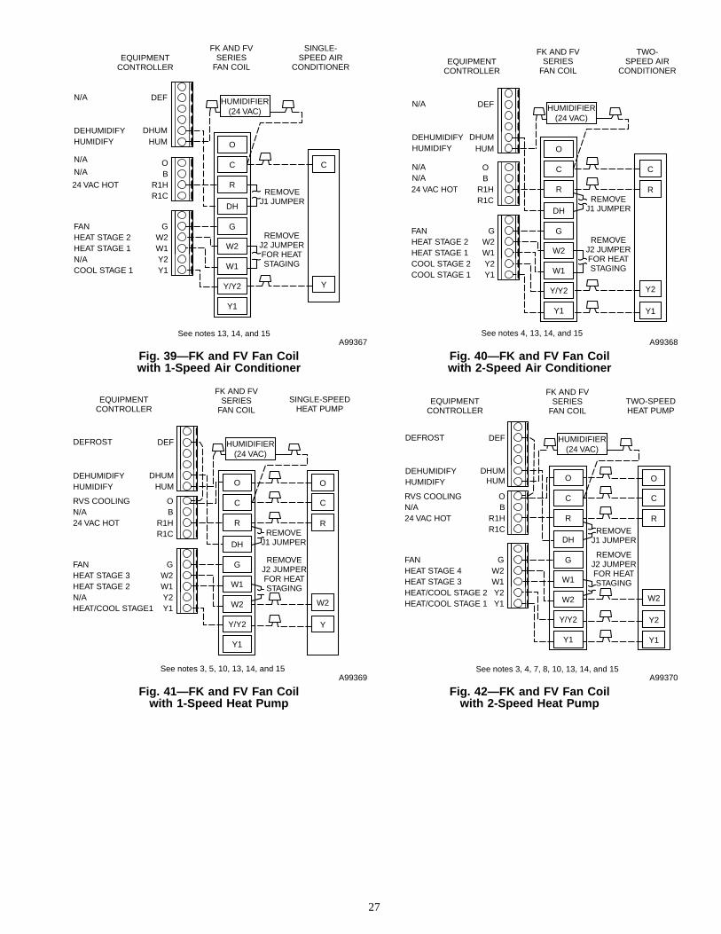
Fig. 41—FK and FV Fan Coilwith 1-Speed Heat Pump
A99369
C
W2
OB
RVS COOLINGN/A
R1H
FK AND FVSERIES
FAN COILSINGLE-SPEED
HEAT PUMP
REMOVEJ1 JUMPER
REMOVEJ2 JUMPERFOR HEATSTAGING
EQUIPMENTCONTROLLER
24 VAC HOTR1C
W2W1
G
Y2Y1
HEAT STAGE 3HEAT STAGE 2
FAN
N/AHEAT/COOL STAGE1
O
R
Y
C
R
DH
W1
G
W2
Y/Y2
Y1
O
DEFROST
DEHUMIDIFYHUMIDIFY
DEF
DHUMHUM
HUMIDIFIER(24 VAC)
See notes 3, 5, 10, 13, 14, and 15
Fig. 39—FK and FV Fan Coilwith 1-Speed Air Conditioner
A99367
C
Y
OB
R1H
FK AND FVSERIES
FAN COIL
SINGLE-SPEED AIR
CONDITIONER
REMOVEJ1 JUMPER
REMOVEJ2 JUMPERFOR HEATSTAGING
EQUIPMENTCONTROLLER
24 VAC HOTR1C
W2W1
G
Y2Y1
HEAT STAGE 2HEAT STAGE 1
FAN
N/ACOOL STAGE 1
C
R
DH
W2
G
W1
Y/Y2
Y1
O
N/A
N/A
N/A
DEHUMIDIFYHUMIDIFY
DEF
DHUMHUM
HUMIDIFIER(24 VAC)
See notes 13, 14, and 15
Fig. 42—FK and FV Fan Coilwith 2-Speed Heat Pump
A99370
C
W2
OB
RVS COOLINGN/A
R1H
FK AND FVSERIES
FAN COILTWO-SPEEDHEAT PUMP
REMOVEJ1 JUMPER
REMOVEJ2 JUMPERFOR HEATSTAGING
EQUIPMENTCONTROLLER
24 VAC HOTR1C
W2W1
G
Y2Y1
HEAT STAGE 4HEAT STAGE 3
FAN
HEAT/COOL STAGE 2HEAT/COOL STAGE 1
O
R
Y2
Y1
C
R
DH
W1
G
W2
Y/Y2
Y1
O
DEFROST
DEHUMIDIFYHUMIDIFY
DEF
DHUMHUM
HUMIDIFIER(24 VAC)
See notes 3, 4, 7, 8, 10, 13, 14, and 15
Fig. 40—FK and FV Fan Coilwith 2-Speed Air Conditioner
A99368
C
Y2
OB
R1H
FK AND FVSERIES
FAN COIL
TWO-SPEED AIR
CONDITIONER
REMOVEJ1 JUMPER
REMOVEJ2 JUMPERFOR HEATSTAGING
EQUIPMENTCONTROLLER
24 VAC HOTR1C
W2W1
G
Y2Y1
HEAT STAGE 2HEAT STAGE 1
FAN
COOL STAGE 2COOL STAGE 1
R
Y1
C
R
DH
W2
G
W1
Y/Y2
Y1
O
N/A
N/AN/A
DEHUMIDIFYHUMIDIFY
DEF
DHUMHUM
HUMIDIFIER(24 VAC)
See notes 4, 13, 14, and 15
27

WIRING DIAGRAM NOTES1. Heat pump must have a high pressure switch for dual fuel applications.
2. Outdoor Air Sensor must be attached for all dual fuel applications.
3. Dip switch setting No. 1 must be OFF (open) for heat pump operation.
4. Dip switch setting No. 2 must be OFF (open) for 2-speed compressor operation.
5. Dip switch setting No. 3 must be OFF (open) for 3-stage heat operation.
6. Dip switch setting No. 8 must be OFF (open) for dual fuel operation.
7. Refer to outdoor equipment Installation Instructions for proper setup.
8. Select "ZONE" position on 2-speed heat pump control board.
9. Do not select "dual fuel" option on 2-speed heat pump control board. The zoning system will control this function.
10. Jumper wire must be installed between DEF and O terminal at Equipment Controller for proper defrost operation.
11. Configuration Option No. 11 (at User Interface) must be activated to select dual fuel crossover temperature. Configuration Option No. 8 isoptional in selecting an auxiliary heat lockout temperature.
12. It is recommended to let the zoning system control furnace staging. Refer to indoor unit Installation Instructions for proper setup.
13. Refer to Fan Coil Installation Instructions for features and additional wiring information.
14. To activate dehumidify function on FK or FV, remove J1 jumper at fan coil control board.
15. Configuration Option No. 5 (at User Interface) should be activated to indicate variable-speed (ICM) blower motor.
16. To activate dehumidify feature on variable-speed 80% non-condensing furnace, disconnect green (DHUM) wire from G on furnace controlboard and connect to dehumidify terminal on Equipment Controller.
17. To activate dehumidify feature on older style variable-speed condensing furnaces (i.e., 58MVP) that do not have a DE connection, a pilot duty24vac relay must be used.
18. Remove DE jumper to enable DEHUM input on furnace control board.
19. No connection should be made to the furnace HUM terminal.
SERVICE TRAINING
Packaged Service Training programs are an excellent way to increase your knowledge of the equipment discussed in this manual, including: • Unit Familiarization • Maintenance • Installation Overview • Operating Sequence A large selection of product, theory, and skills programs is available, using popular video-based formats and materials. All include video and/or slides, plus companion book. Classroom Service Training plus "hands-on" the products in our labs can mean increased confidence that really pays dividends in faster troubleshooting, fewer callbacks. Course descriptions and schedules are in our catalog.
CALL FOR FREE CATALOG 1-800-962-9212
[ ] Packaged Service Training [ ] Classroom Service TrainingA94328
Copyright 1999 CARRIER Corp. • 7310 W. Morris St. • Indianapolis, IN 46231 zkit14si
Manufacturer reserves the right to discontinue, or change at any time, specifications or designs without notice and without incurring obligations.Book 1 1 4 4Tab 3a 5a 2a 5a
PC 101 Catalog No. 809-538 Printed in U.S.A. Form ZONEKIT-14SI Pg 28 12-99 Replaces: ZONEKIT-13SI