VisiSight Photoelectric Sensors with IO-Link Interface manual contains information for the...
92
VisiSight Photoelectric Sensors with IO-Link Interface Catalog Numbers 42JT-DxLAT1-x, 42JT-PxLAT1-x, 42JT-RxLAT1-x, 42JT-C2LAT1-x, 42JT-F5LET1-x, 42EF-BxLAT1-x User Manual Original Instructions
Transcript of VisiSight Photoelectric Sensors with IO-Link Interface manual contains information for the...

VisiSight Photoelectric Sensors with IO-Link InterfaceCatalog Numbers 42JT-DxLAT1-x, 42JT-PxLAT1-x, 42JT-RxLAT1-x, 42JT-C2LAT1-x, 42JT-F5LET1-x, 42EF-BxLAT1-x
User ManualOriginal Instructions

Important User Information
Read this document and the documents listed in the additional resources section about installation, configuration, and operation of this equipment before you install, configure, operate, or maintain this product. Users are required to familiarize themselves with installation and wiring instructions in addition to requirements of all applicable codes, laws, and standards.
Activities including installation, adjustments, putting into service, use, assembly, disassembly, and maintenance are required to be carried out by suitably trained personnel in accordance with applicable code of practice.
If this equipment is used in a manner not specified by the manufacturer, the protection provided by the equipment may be impaired.
In no event will Rockwell Automation, Inc. be responsible or liable for indirect or consequential damages resulting from the use or application of this equipment.
The examples and diagrams in this manual are included solely for illustrative purposes. Because of the many variables and requirements associated with any particular installation, Rockwell Automation, Inc. cannot assume responsibility or liability for actual use based on the examples and diagrams.
No patent liability is assumed by Rockwell Automation, Inc. with respect to use of information, circuits, equipment, or software described in this manual.
Reproduction of the contents of this manual, in whole or in part, without written permission of Rockwell Automation, Inc., is prohibited
Throughout this manual, when necessary, we use notes to make you aware of safety considerations.
Labels may also be on or inside the equipment to provide specific precautions.
WARNING: Identifies information about practices or circumstances that can cause an explosion in a hazardous environment, which may lead to personal injury or death, property damage, or economic loss.
ATTENTION: Identifies information about practices or circumstances that can lead to personal injury or death, property damage, or economic loss. Attentions help you identify a hazard, avoid a hazard, and recognize the consequence.
IMPORTANT Identifies information that is critical for successful application and understanding of the product.
SHOCK HAZARD: Labels may be on or inside the equipment, for example, a drive or motor, to alert people that dangerous voltage may be present.
BURN HAZARD: Labels may be on or inside the equipment, for example, a drive or motor, to alert people that surfaces may reach dangerous temperatures.
ARC FLASH HAZARD: Labels may be on or inside the equipment, for example, a motor control center, to alert people to potential Arc Flash. Arc Flash will cause severe injury or death. Wear proper Personal Protective Equipment (PPE). Follow ALL Regulatory requirements for safe work practices and for Personal Protective Equipment (PPE).
Table of Contents
PrefaceWho Should Use This Manual . . . . . . . . . . . . . . . . . . . . . . . . . . . . . . . . . . .7Definitions . . . . . . . . . . . . . . . . . . . . . . . . . . . . . . . . . . . . . . . . . . . . . . . . . . . . .7Abbreviations . . . . . . . . . . . . . . . . . . . . . . . . . . . . . . . . . . . . . . . . . . . . . . . . . .8Additional Resources . . . . . . . . . . . . . . . . . . . . . . . . . . . . . . . . . . . . . . . . . . .8
Chapter 1Product Overview Product Description . . . . . . . . . . . . . . . . . . . . . . . . . . . . . . . . . . . . . . . . . . . .9
Operation Modes . . . . . . . . . . . . . . . . . . . . . . . . . . . . . . . . . . . . . . . . . . . . . . .9Standard I/O (SIO) Mode . . . . . . . . . . . . . . . . . . . . . . . . . . . . . . . . . . .9IO-Link Mode . . . . . . . . . . . . . . . . . . . . . . . . . . . . . . . . . . . . . . . . . . . . . .9
Features . . . . . . . . . . . . . . . . . . . . . . . . . . . . . . . . . . . . . . . . . . . . . . . . . . . . . . 10
Chapter 2Installation User Interface . . . . . . . . . . . . . . . . . . . . . . . . . . . . . . . . . . . . . . . . . . . . . . . . 11
Indicator Status . . . . . . . . . . . . . . . . . . . . . . . . . . . . . . . . . . . . . . . . . . . 11Alignment Indication . . . . . . . . . . . . . . . . . . . . . . . . . . . . . . . . . . . . . 12
Specifications . . . . . . . . . . . . . . . . . . . . . . . . . . . . . . . . . . . . . . . . . . . . . . . . . 12Mounting . . . . . . . . . . . . . . . . . . . . . . . . . . . . . . . . . . . . . . . . . . . . . . . . . . . . 13Dimensions . . . . . . . . . . . . . . . . . . . . . . . . . . . . . . . . . . . . . . . . . . . . . . . . . . 13Margin Curves
Typical Response Curves . . . . . . . . . . . . . . . . . . . . . . . . . . . . . . . . . . 13Wiring . . . . . . . . . . . . . . . . . . . . . . . . . . . . . . . . . . . . . . . . . . . . . . . . . . . . . . . 17
Output Wiring . . . . . . . . . . . . . . . . . . . . . . . . . . . . . . . . . . . . . . . . . . . 17
Chapter 3Teaching the VisiSight Sensor in Standard I/O (SIO) Mode
Teach Overview . . . . . . . . . . . . . . . . . . . . . . . . . . . . . . . . . . . . . . . . . . . . . . 19Teach Sensitivity/Sensing Range . . . . . . . . . . . . . . . . . . . . . . . . . . . . . . . 19Diffuse Teach Procedure . . . . . . . . . . . . . . . . . . . . . . . . . . . . . . . . . . . . . . 19Standard Teach . . . . . . . . . . . . . . . . . . . . . . . . . . . . . . . . . . . . . . . . . . . . . . . 19Polarized Retroreflective Teach Procedure . . . . . . . . . . . . . . . . . . . . . . 20Standard Teach . . . . . . . . . . . . . . . . . . . . . . . . . . . . . . . . . . . . . . . . . . . . . . . 20Transmitted Beam Teach Procedure . . . . . . . . . . . . . . . . . . . . . . . . . . . 21Standard Teach . . . . . . . . . . . . . . . . . . . . . . . . . . . . . . . . . . . . . . . . . . . . . . . 21Light or Dark Operate Selection . . . . . . . . . . . . . . . . . . . . . . . . . . . . . . . 22Output Type Selection (Auto PNP or NPN, Dedicated NPN, Dedicated PNP) . . . . . . . . . . . . . . . . . . . . . . . . . . . . . . . . . . . . . . . . . . . . . 23Push Button Lock/Unlock . . . . . . . . . . . . . . . . . . . . . . . . . . . . . . . . . . . . 23Remote Teach (RT) . . . . . . . . . . . . . . . . . . . . . . . . . . . . . . . . . . . . . . . . . . 24
Rockwell Automation Publication 42JT-UM001B-EN-P - June 2017 3

Table of Contents
Chapter 4VisiSight Sensor with IO-Link Overview
Premier Integration . . . . . . . . . . . . . . . . . . . . . . . . . . . . . . . . . . . . . . . . . . . 25VisiSight Sensor IO-Link Features . . . . . . . . . . . . . . . . . . . . . . . . . . . . . 26
Triggered . . . . . . . . . . . . . . . . . . . . . . . . . . . . . . . . . . . . . . . . . . . . . . . . . 26Margin Low Alarm . . . . . . . . . . . . . . . . . . . . . . . . . . . . . . . . . . . . . . . . 26Serialization . . . . . . . . . . . . . . . . . . . . . . . . . . . . . . . . . . . . . . . . . . . . . . 26Polarity . . . . . . . . . . . . . . . . . . . . . . . . . . . . . . . . . . . . . . . . . . . . . . . . . . 27Lock and Unlock User Interface . . . . . . . . . . . . . . . . . . . . . . . . . . . . 27Standard Teach . . . . . . . . . . . . . . . . . . . . . . . . . . . . . . . . . . . . . . . . . . . 27Precision Teach . . . . . . . . . . . . . . . . . . . . . . . . . . . . . . . . . . . . . . . . . . . 27Dynamic Teach . . . . . . . . . . . . . . . . . . . . . . . . . . . . . . . . . . . . . . . . . . . 27Automatic Device Configuration (ADC) . . . . . . . . . . . . . . . . . . . 27Application Specific Name (ASN) . . . . . . . . . . . . . . . . . . . . . . . . . . 28Tag Naming for I/O Data . . . . . . . . . . . . . . . . . . . . . . . . . . . . . . . . . 28
Chapter 5Installing the VisiSight Sensor for IO-Link Mode
Hardware . . . . . . . . . . . . . . . . . . . . . . . . . . . . . . . . . . . . . . . . . . . . . . . . 29Software . . . . . . . . . . . . . . . . . . . . . . . . . . . . . . . . . . . . . . . . . . . . . . . . . . 29
Example: Setting Up the Hardware . . . . . . . . . . . . . . . . . . . . . . . . . . . . . 30
Chapter 6Creating a Project AOP Installation . . . . . . . . . . . . . . . . . . . . . . . . . . . . . . . . . . . . . . . . . . . . . 35
Chapter 7Configuring the IO-Link Master . . . . . . . . . . . . . . . . . . . . . . . . . . . . . . . . . . . . . . . . . . . . . . . . . . . . . . . . . . . . . . 37
Chapter 8Registering the VisiSight Sensor IODD
. . . . . . . . . . . . . . . . . . . . . . . . . . . . . . . . . . . . . . . . . . . . . . . . . . . . . . . . . . . . . . 41
Chapter 9Connecting the VisiSight Sensor to the IO-Link Master
. . . . . . . . . . . . . . . . . . . . . . . . . . . . . . . . . . . . . . . . . . . . . . . . . . . . . . . . . . . . . . 45
4 Rockwell Automation Publication 42JT-UM001B-EN-P - June 2017

Table of Contents
Chapter 10Exploring the VisiSight Sensor IO-Link Parameters
Overview . . . . . . . . . . . . . . . . . . . . . . . . . . . . . . . . . . . . . . . . . . . . . . . . . . . . . 47Common Tab . . . . . . . . . . . . . . . . . . . . . . . . . . . . . . . . . . . . . . . . . . . . 47Identification Tab . . . . . . . . . . . . . . . . . . . . . . . . . . . . . . . . . . . . . . . . . 47Parameter Tab . . . . . . . . . . . . . . . . . . . . . . . . . . . . . . . . . . . . . . . . . . . . 47Diagnosis Tab . . . . . . . . . . . . . . . . . . . . . . . . . . . . . . . . . . . . . . . . . . . . 47
IO-Link Configuration . . . . . . . . . . . . . . . . . . . . . . . . . . . . . . . . . . . . . . . 48Common Tab . . . . . . . . . . . . . . . . . . . . . . . . . . . . . . . . . . . . . . . . . . . . 48Minimum Cycle Time . . . . . . . . . . . . . . . . . . . . . . . . . . . . . . . . . . . . . 49Identification Tab . . . . . . . . . . . . . . . . . . . . . . . . . . . . . . . . . . . . . . . . . 49Parameter Tab . . . . . . . . . . . . . . . . . . . . . . . . . . . . . . . . . . . . . . . . . . . . 50Diagnosis Tab . . . . . . . . . . . . . . . . . . . . . . . . . . . . . . . . . . . . . . . . . . . . 51
Manage Parameter Differences between IO-Link Devices and Controllers . . . . . . . . . . . . . . . . . . . . . . . . . . . . . . . . . . . . . . . . . . . . . . . . . . 52
Chapter 11Teaching the VisiSight Sensor on IO-Link
Static Teach on IO-Link . . . . . . . . . . . . . . . . . . . . . . . . . . . . . . . . . . . . . . 57Precision Teach on IO-Link . . . . . . . . . . . . . . . . . . . . . . . . . . . . . . . . . . . 58Dynamic Teach on IO-Link . . . . . . . . . . . . . . . . . . . . . . . . . . . . . . . . . . . 59Controller Tags . . . . . . . . . . . . . . . . . . . . . . . . . . . . . . . . . . . . . . . . . . . . . . . 61
Chapter 12Installing the Sensor with Studio 5000
Sample Code . . . . . . . . . . . . . . . . . . . . . . . . . . . . . . . . . . . . . . . . . . . . . . . . . 63Sample Routines . . . . . . . . . . . . . . . . . . . . . . . . . . . . . . . . . . . . . . . . . . . . . . 65Initial Setup . . . . . . . . . . . . . . . . . . . . . . . . . . . . . . . . . . . . . . . . . . . . . . . . . . 68To Perform a Static Teach . . . . . . . . . . . . . . . . . . . . . . . . . . . . . . . . . . . . . 68Precision Teach . . . . . . . . . . . . . . . . . . . . . . . . . . . . . . . . . . . . . . . . . . . . . . . 69
Precision Teach Sample Code . . . . . . . . . . . . . . . . . . . . . . . . . . . . . . 69Dynamic Teach . . . . . . . . . . . . . . . . . . . . . . . . . . . . . . . . . . . . . . . . . . . . . . . 70
Dynamic Teach Sample Code . . . . . . . . . . . . . . . . . . . . . . . . . . . . . . 70To Test the New Settings of the Sensor . . . . . . . . . . . . . . . . . . . . . 71
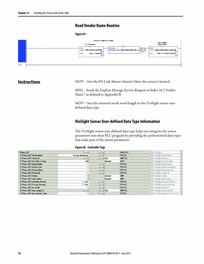
Read a VisiSight Sensor Parameters Using Explicit Messages . . . . . . 71Read Vendor Name Routine . . . . . . . . . . . . . . . . . . . . . . . . . . . . . . . 71
Instructions . . . . . . . . . . . . . . . . . . . . . . . . . . . . . . . . . . . . . . . . . . . . . . . . . . 71VisiSight Sensor User-defined Data Type Information. . . . . . . . 72
Chapter 13Troubleshooting Checklist . . . . . . . . . . . . . . . . . . . . . . . . . . . . . . . . . . . . . . . . . . . . . . . . . . . . . 73
Appendix AInstalling the Add-on Profile Introduction . . . . . . . . . . . . . . . . . . . . . . . . . . . . . . . . . . . . . . . . . . . . . . . . . 75
Performing the Installation . . . . . . . . . . . . . . . . . . . . . . . . . . . . . . . . . . . . 75
Rockwell Automation Publication 42JT-UM001B-EN-P - June 2017 5
Table of Contents
Appendix BDevice Parameters Identification Tab . . . . . . . . . . . . . . . . . . . . . . . . . . . . . . . . . . . . . . . . . . . . 77
Parameter Tab . . . . . . . . . . . . . . . . . . . . . . . . . . . . . . . . . . . . . . . . . . . . . . . . 78Diagnosis Tab . . . . . . . . . . . . . . . . . . . . . . . . . . . . . . . . . . . . . . . . . . . . . . . . 79Process Data . . . . . . . . . . . . . . . . . . . . . . . . . . . . . . . . . . . . . . . . . . . . . . . . . . 79
Appendix CMessage Structure and Configuration Examples
Configuring a Message Instruction . . . . . . . . . . . . . . . . . . . . . . . . . . . . . 81Example Format of a Read Message . . . . . . . . . . . . . . . . . . . . . . . . . 81Read Data from the Sensor . . . . . . . . . . . . . . . . . . . . . . . . . . . . . . . . . 83Example Format of a Write Message . . . . . . . . . . . . . . . . . . . . . . . . 83Validation of Write . . . . . . . . . . . . . . . . . . . . . . . . . . . . . . . . . . . . . . . 85Service Code . . . . . . . . . . . . . . . . . . . . . . . . . . . . . . . . . . . . . . . . . . . . . . 86Source Length: from Data Structure Tables . . . . . . . . . . . . . . . . . 86
Appendix DError Codes and Events Error Codes . . . . . . . . . . . . . . . . . . . . . . . . . . . . . . . . . . . . . . . . . . . . . . . . . . 89
Event Codes . . . . . . . . . . . . . . . . . . . . . . . . . . . . . . . . . . . . . . . . . . . . . . . . . . 89
6 Rockwell Automation Publication 42JT-UM001B-EN-P - June 2017

Preface
This manual contains information for the VisiSight™ Photoelectric Sensors with IO-Link Interface. It describes the procedures that you use to install, wire, and troubleshoot your sensor.
Who Should Use This Manual Use this manual if your responsibilities include design, installation, programming, or troubleshooting of control systems that use solid-state temperature sensors including catalog numbers:
• 42JT-DxLAT1-x• 42JT-PxLAT1-x• 42JT-RxLAT1-x• 42JT-C2LAT1-x• 42JT-F5LET1-x• 42EF-BxLAT1-x
You must have a basic understanding of electrical circuitry and familiarity with solid-state temperature sensors. If you do not have this knowledge, obtain the proper training before using this product.
Definitions Publication AG-7.1 contains a glossary of terms and abbreviations that are used by Rockwell Automation to describe industrial automation systems. The following is a list of specific terms and abbreviations that are used in this manual.
• L.O. (Light Operate) - The state at which the output changes from OFF to ON and the target reflects the light back to the sensor.
• D.O. (Dark Operate) - The state at which the output changes from OFF to ON and the target does not reflect light back to the sensor.
• PLC - A programmable logic controller or a programmable automation controller.
• Response Time - Describes the time between the trigger of one input to the OFF state of the output. Throughout this manual, the safety outputs are described as turning off immediately, which means that the safety outputs turn off within the response time.
Rockwell Automation Publication 42JT-UM001B-EN-P - June 2017 7

Preface
Abbreviations
Additional Resources These documents contain additional information concerning related products from Rockwell Automation.
You can view or download publications athttp://www.rockwellautomation.com/global/literature-library/overview.page. To order paper copies of technical documentation, contact your local Allen-Bradley distributor or Rockwell Automation sales representative.
ADC Automatic Device Configuration
AOI Add-on Instruction
AOP Add-on Profile
ASN Application Specific Name
IEC International Electrotechnical Commission
IODD I/O Device Description
NEC National Electric Code
QD Quick Disconnect
RGB Red, Green, Blue
SIO Standard I/O
TB Teach Background
TD Teach Dynamic
TM Teach Mark
Resource Description
Industrial Automation Wiring and Grounding Guidelines, publication 1770-4.1
Provides general guidelines for installing a Rockwell Automation industrial system.
Product Certifications website, http://www.rockwellautomation.com/global/certification/overview.page
Provides declarations of conformity, certificates, and other certification details.
8 Rockwell Automation Publication 42JT-UM001B-EN-P - June 2017

Chapter 1
Product Overview
Product Description The VisiSight™ family of sensors offers a wide range of sensing modes and a teach push button that simplifies sensitivity adjustment and offers light versus dark operate output selection. The unique “Auto PNP/NPN” output continuously monitors how the load is connected and automatically configures the output for proper operation and output light-emitting diode to indicate correct output status.
The embedded IO-Link communication interface enables the sensor to provide more diagnostics information to help reduce downtime and increase productivity.
Operation Modes The sensor can operate in two modes.
Standard I/O (SIO) Mode
The sensor default-operation mode. The sensor outputs and user interface behave as described in the installation instructions included with the product. This mode of operation is active when the sensor is connected to digital input devices such as a PLC inputs modules, distribution boxes, and input terminal connections.
IO-Link Mode
This mode is automatically activated when the sensor is connected to an IO-Link enabled master device. Upon entering this mode, the green status indicator on the sensor starts blinking at a rate of 1 Hz to indicate that IO-Link communication has been successfully established with the master. The sensor transmits more parameter and diagnostic information that can be accessed via the PLC process data. No user intervention is required to enable this functionality within the sensor.
Rockwell Automation Publication 42JT-UM001B-EN-P - June 2017 9
Chapter 1 Product Overview
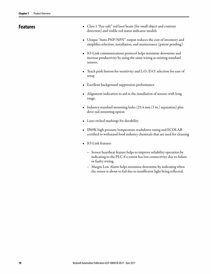
Features • Class 1 “Eye-safe” red laser beam (for small object and contrast detection) and visible red status indicator models
• Unique “Auto PNP/NPN” output reduces the cost of inventory and simplifies selection, installation, and maintenance (patent pending)
• IO-Link communications protocol helps minimize downtime and increase productivity by using the same wiring as existing standard sensors.
• Teach push button for sensitivity and L.O./D.O. selection for ease of setup
• Excellent background suppression performance
• Alignment indication to aid in the installation of sensors with long range.
• Industry-standard mounting holes (25.4 mm (1 in.) separation) plus dove-tail mounting option
• Laser etched markings for durability
• IP69K high pressure/temperature washdown rating and ECOLAB certified to withstand food industry chemicals that are used for cleaning
• IO-Link features
– Sensor heartbeat feature helps to improve reliability operation by indicating to the PLC if a sensor has lost connectivity due to failure or faulty wiring.
– Margin Low Alarm helps minimize downtime by indicating when the sensor is about to fail due to insufficient light being reflected.
10 Rockwell Automation Publication 42JT-UM001B-EN-P - June 2017
Chapter 2
Installation
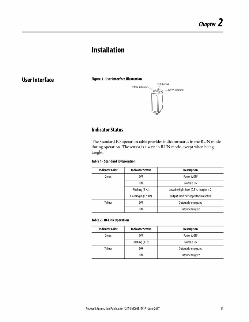
User Interface Figure 1 - User Interface Illustration
Indicator Status
The Standard IO operation table provides indicator status in the RUN mode during operation. The sensor is always in RUN mode, except when being taught.
Table 1 - Standard IO Operation
Table 2 - IO-Link Operation
Indicator Color Indicator Status Description
Green OFF Power is OFF
ON Power is ON
Flashing (6 Hz) Unstable light level (0.5 < margin < 2)
Flashing in (1.5 Hz) Output short circuit protection active
Yellow OFF Output de-energized
ON Output energized
Indicator Color Indicator Status Description
Green OFF Power is OFF
Flashing (1 Hz) Power is ON
Yellow OFF Output de-energized
ON Output energized
Yellow IndicatorPush Button
Green Indicator
Rockwell Automation Publication 42JT-UM001B-EN-P - June 2017 11
Chapter 2 Installation
Alignment Indication For short range applications, the visible light beam of the sensor suffices as alignment aid.
The alignment feature can be used for longer range applications. Alignment of the sensor is indicated via change in intensity of the green status indicator in the Alignment Mode, as follows:
1. Press and release the push button twice within 3 seconds. After 3 seconds, the green status indicator turns OFF for 0.5 second indicating the sensor is in the alignment mode.
2. Align sensor to the target to be detected. Intensity of green status indicator increases with better alignment. Secure it in a position that yields the highest intensity of the green status indicator. Press and release the button once to return to the RUN mode, or the sensor automatically returns to RUN mode in two minutes.
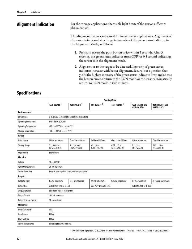
Specifications
1 See Connection Types table. 2 ECOLAB on -P4 and -A2 models only. 3 UL: -20…+50°C (-4…122°F) 4 UL: Class 2 source
Sensing Mode
42JT-D2LAT1-1 42JT-D8LAT1-1 42JT-P2LAT1-1 42JT-P8LAT1-1 42JT-E2EZB1- and42JT-R9LAT1-1
42JT-E8EZB1- and42JT-R8LAT1-1
Environmental
Certifications c-UL-us and CE Marked for all applicable directives
Operating Environment IP67, IP69K, ECOLAB 2
Operating Temperature -20…+60 °C (-4…+140 °F) 3
Storage Temperature -20…+80 °C (-4…+179 °F)
Optical
Light Source Visible red 660 nm Class 1 laser 650 nm Visible red 660 nm Class 1 laser 650 nm Visible red 660 nm Class 1 laser 650 nm
Sensing Range 3…800 mm (0.12…31.5 in.)
1…250 mm (0.04…9.8 in.)
0.1…6 m (0.33…19.7 ft)
0.05…13 m (0.16…42.7 ft)
0…13 m (0…42.65 ft)
0.05…18 m (0…59.05 ft)
Adjustments Push button
Electrical
Voltage 10…30V DC 4
Current Consumption 30 mA maximum
Sensor Protection Reverse polarity, short circuit, overload protection
Outputs
Response Time 0.5 ms maximum 0.33 ms maximum 0.5 ms, maximum 0.25 ms, maximum 0.5 ms, maximum 0.25 ms, maximum
Output Type Auto NPN or PNP or IO-Link Auto PNP/NPN or IO-Link Auto PNP/NPN or IO-Link
Output Function Selectable light or dark operate
Output Current 100 mA maximum
Output Leakage Current 10 µA maximum
Mechanical
Housing Material ABS
Lens Material PMMA
Cover Material PMMA
Optional Accessories Mounting brackets, cordsets
12 Rockwell Automation Publication 42JT-UM001B-EN-P - June 2017
Installation Chapter 2
Mounting Securely mount the sensor on a firm, stable surface, or support. An application, which is subject to excessive movement or vibration, can cause intermittent operation.
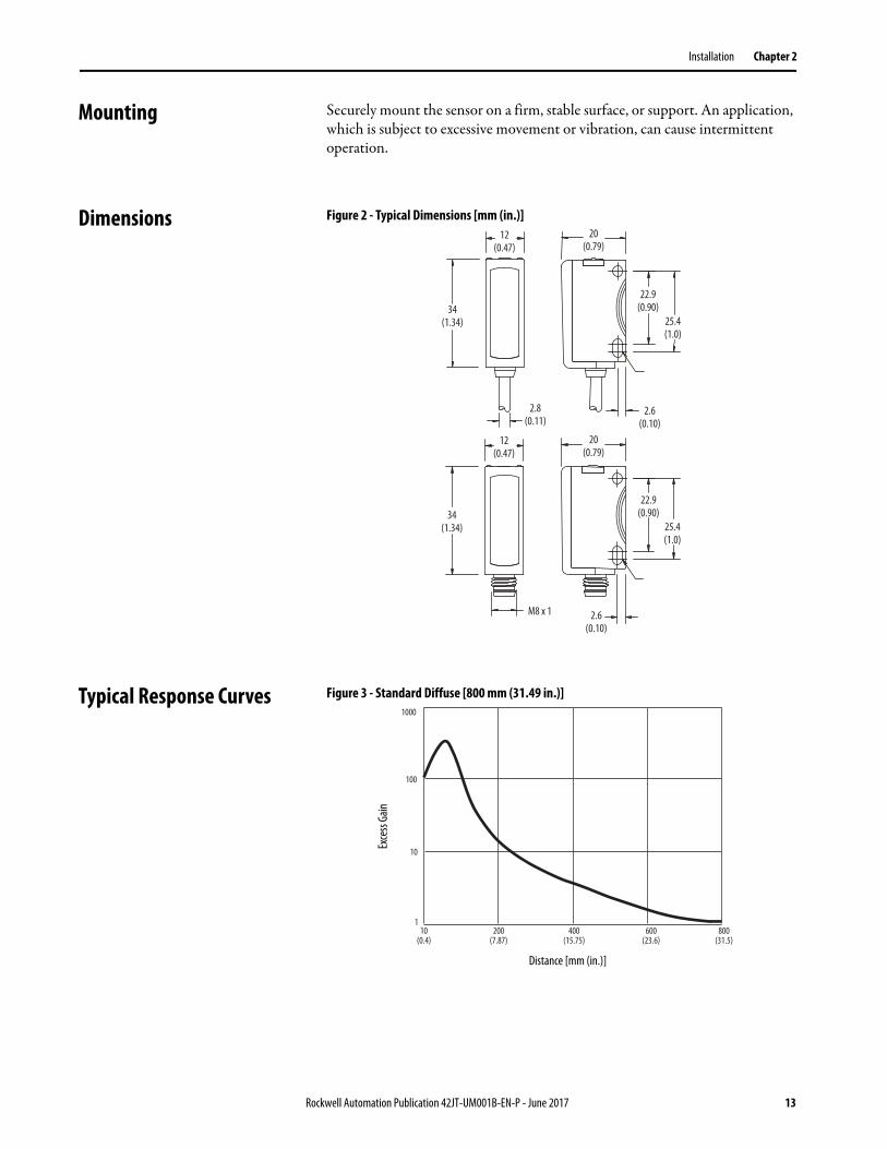
Dimensions Figure 2 - Typical Dimensions [mm (in.)]
Typical Response Curves Figure 3 - Standard Diffuse [800 mm (31.49 in.)]
12(0.47)
M8 x 1
34(1.34)
22.9(0.90)
25.4(1.0)
2.6(0.10)
20(0.79)
12(0.47)
34(1.34)
22.9(0.90)
25.4(1.0)
2.6(0.10)
20(0.79)
2.8(0.11)
1000
100
1
10
10(0.4)
800(31.5)
600(23.6)
400(15.75)
200(7.87)
Distance [mm (in.)]
Exce
ss Ga
in
Rockwell Automation Publication 42JT-UM001B-EN-P - June 2017 13

Chapter 2 Installation
Figure 4 - Spot Size [800 mm (31.49 in.)]
Figure 5 - Laser Diffuse [250 mm (9.84 in.)]
Figure 6 - Laser Spot Size [250 mm (9.84 in.)])
00
10
20
30
40
50
60
70
horizontal = verticalhorizontal = verticalhorizontal = verticalhorizontal = verticalhorizontal = verticalhorizontal = verticalhorizontal = verticalhorizontal = verticalhorizontal = verticalhorizontal = verticalhorizontal = verticalhorizontal = verticalhorizontal = verticalhorizontal = vertical
800(31.5)
600(23.6)
400(15.75)
200(7.87)
Distance [mm (in.)]Siz
e [m
m]
00
5
10
15
20
25
30
Distance [mm]
Exce
ss Ga
in
200(7.87)
150(5.91)
100(3.94)
50(1.96)
250(9.84)
Distance [mm (in.)]
Exce
ss Ga
in
00.0
0.5
1.0
1.5
2.0
horizontal = vertical
200(7.87)
150(5.91)
100(3.94)
50(1.96)
250(9.84)
Distance [mm (in.)]
Size [
mm
]
14 Rockwell Automation Publication 42JT-UM001B-EN-P - June 2017
Installation Chapter 2
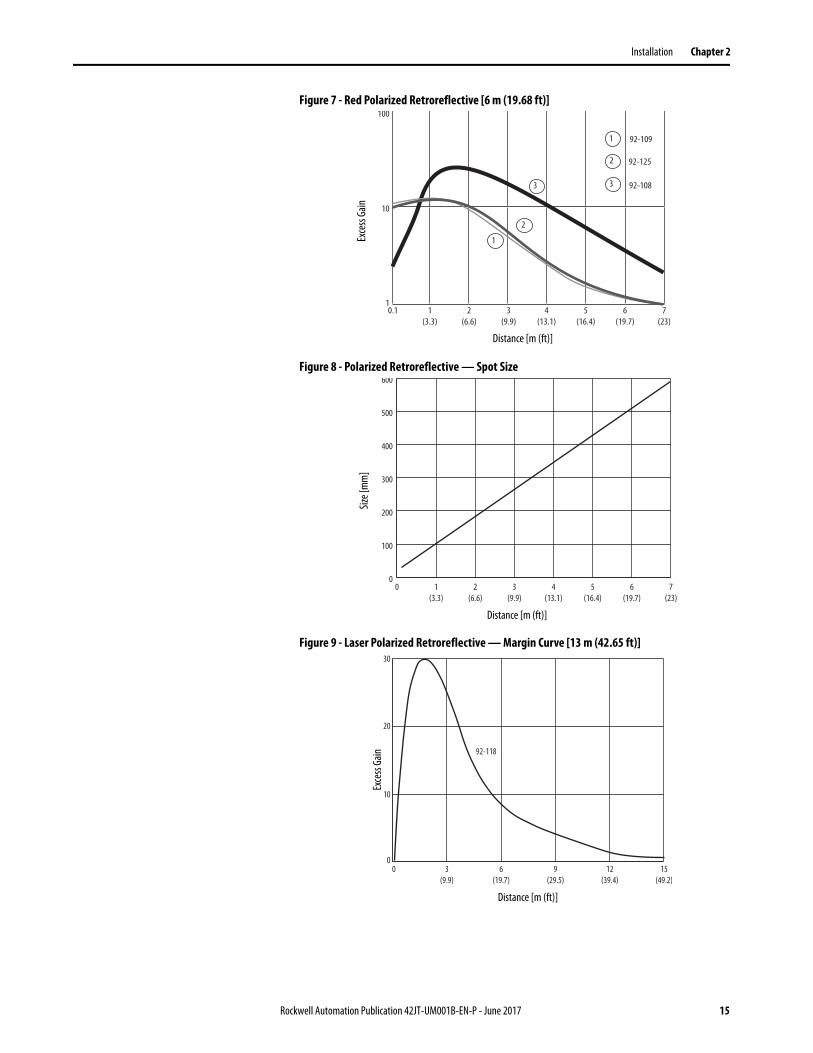
Figure 7 - Red Polarized Retroreflective [6 m (19.68 ft)]
Figure 8 - Polarized Retroreflective — Spot Size
Figure 9 - Laser Polarized Retroreflective — Margin Curve [13 m (42.65 ft)]
0.1 2(6.6)
1(3.3)
4(13.1)
7(23)
5(16.4)
6(19.7)
3(9.9)
10
1
100
3
1
3
2
1
2
92-109
92-108
92-125
Distance [m (ft)]
Exce
ss Ga
in
0 1(3.3)
2(6.6)
3(9.9)
4(13.1)
5(16.4)
6(19.7)
7(23)
0
100
200
300
400
500
600
Distance [m (ft)]
Size [
mm
]
0 3(9.9)
6(19.7)
9(29.5)
12(39.4)
15(49.2)
0
10
20
30
92-118
Distance [m (ft)]
Exce
ss Ga
in
Rockwell Automation Publication 42JT-UM001B-EN-P - June 2017 15
Chapter 2 Installation
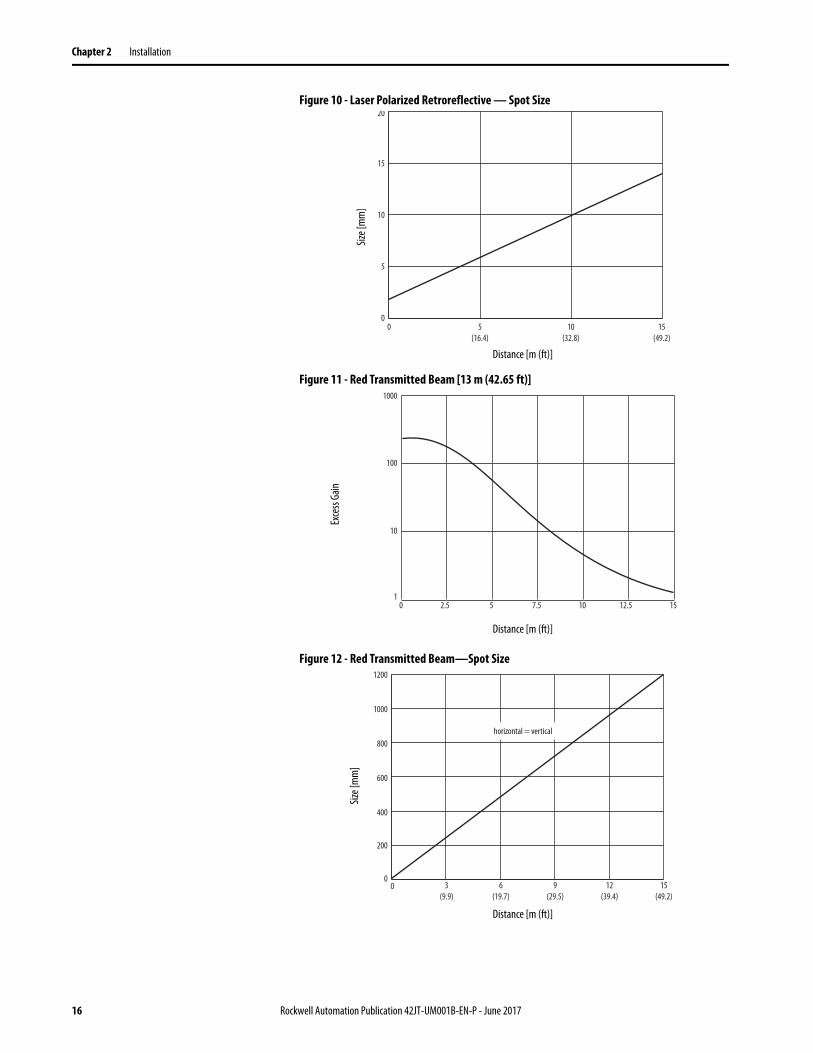
Figure 10 - Laser Polarized Retroreflective — Spot Size
Figure 11 - Red Transmitted Beam [13 m (42.65 ft)]
Figure 12 - Red Transmitted Beam—Spot Size
0 5(16.4)
10(32.8)
15(49.2)
0
5
10
15
20
Distance [m (ft)]Siz
e [m
m]
1000
100
10
10 2.5 5 7.5 10 12.5 15
Distance [m (ft)]
Exce
ss Ga
in
3(9.9)
6(19.7)
9(29.5)
12(39.4)
15(49.2)
00
200
400
600
800
1000
1200
horizontal = vertical
Distance [m (ft)]
Size [
mm
]
16 Rockwell Automation Publication 42JT-UM001B-EN-P - June 2017

Installation Chapter 2
Wiring Figure 13 - Micro (M12) Male QD on Pigtail and Integral Pico (M8) Male QD
Output Wiring
Figure 14 - Transmitted Beam Receiver
Figure 15 - Transmitted Beam Emitter
1 Normal operation: no connection. (Disabled in IO-Link operation.)Remote teach: connect to +V. See Remote Teach (RT) on page 24.Push button lock: connect to -V. See Push Button Lock/Unlock on page 23.
2 For Normal operation, white wire (pin two) and black wire (pin four) needs no connection. To disable light source, connect white wire (pin two) to +V or disable light source via IO-Link.
4
3
1
2
3
2
1
4
M12 Male M8 Male
Brown (1)
Black (4)White (2)
Blue (3)
+V
Output Auto NPN/PNP or IO-LinkRemote Teach/Lock 1
-V
Brown (1)White (2)
Blue (3)
Test 1Black (4) IO-Link
-V 2
+V
Rockwell Automation Publication 42JT-UM001B-EN-P - June 2017 17

Chapter 2 Installation
Notes:
18 Rockwell Automation Publication 42JT-UM001B-EN-P - June 2017
Chapter 3
Teaching the VisiSight Sensor in Standard I/O (SIO) Mode
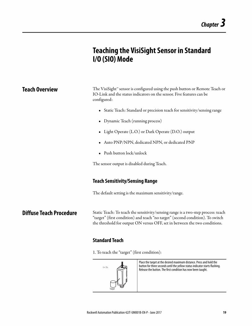
Teach Overview The VisiSight™ sensor is configured using the push button or Remote Teach or IO-Link and the status indicators on the sensor. Five features can be configured:
• Static Teach: Standard or precision teach for sensitivity/sensing range
• Dynamic Teach (running process)
• Light Operate (L.O.) or Dark Operate (D.O.) output
• Auto PNP/NPN, dedicated NPN, or dedicated PNP
• Push button lock/unlock
The sensor output is disabled during Teach.
Teach Sensitivity/Sensing Range
The default setting is the maximum sensitivity/range.
Diffuse Teach Procedure Static Teach: To teach the sensitivity/sensing range is a two-step process: teach “target” (first condition) and teach “no target” (second condition). To switch the threshold for output ON versus OFF, set in between the two conditions.
Standard Teach
1. To teach the “target” (first condition):
Place the target at the desired maximum distance. Press and hold the button for three seconds until the yellow status indicator starts flashing. Release the button. The first condition has now been taught.
t < 3 s
Target
Rockwell Automation Publication 42JT-UM001B-EN-P - June 2017 19

Chapter 3 Teaching the VisiSight Sensor in Standard I/O (SIO) Mode
2. Teach “no target” (second condition):
Precision Teach: If there is nothing in the field of view in step two, the sensing range is set farther than the target to maximize excess gain and improve detection reliability. For a more precise setting with less excess gain, do not remove the target in step two (for example, the target is present for both step one and step two). Also use precision teach for contrast applications.
Restore to factory default setting of maximum range: Perform steps one and two with “no target” in the sensor field of view.
Dynamic Teach (running process): If the targets to be detected are moving with the sensor that is aimed at the running process, press and hold the button for three seconds until the yellow status indicator starts flashing. The sensitivity is automatically taught in the next 30 seconds provided the sensor sees two cycles of “target” and “no target.” The threshold for the switching output ON versus OFF is set in between the two conditions.
Polarized Retroreflective Teach Procedure
Static Teach: To teach the sensitivity/sensing range is a two-step process: teach the reflector (first condition) and teach the “target” (second condition).
Standard Teach
1. To teach the reflector (first condition):
Remove the target. Press and release the button. The teach process is complete.If the push button is not pressed within 30 seconds, the sensor exits teach mode and returns to RUN mode without learning the new setting.
IMPORTANT The sensor can also be taught by teaching “no target” as the first condition and “target” as the second condition.
t < 0.5 s
Align the sensor to the reflector. Press and hold the button for three seconds until the yellow status indicator starts flashing. Release the button. The first condition has been taught.
t < 3 s
Reflector
20 Rockwell Automation Publication 42JT-UM001B-EN-P - June 2017

Teaching the VisiSight Sensor in Standard I/O (SIO) Mode Chapter 3
2. Teach “target” (second condition):
Restore to factory default setting of maximum range: Perform steps 1 and 2 with “no target” in the sensor field of view and no emitter.
Dynamic Teach (running process): If the targets to be detected are moving with the sensor that is aimed at the running process, press and hold the button for three seconds until the yellow status indicator starts flashing. The sensitivity is automatically taught in the next 30 seconds provide
Transmitted Beam Teach Procedure
Static Teach: To teach the receiver facing, the emitter (first condition) and teach the “target” (second condition).
Standard Teach
1. To teach the receiver pointed at the emitter (first condition):
2. Teach “target” (second condition):
Insert the target between the sensor and the reflector. Press and release the button. The teach process is complete.If the push button is not pressed within 30 seconds, the sensor exits teach mode and returns to RUN mode without learning the new setting.
t < 0.5 s
Target
Reflector
IMPORTANT No teaching is needed for most applications. The teaching is only necessary for targets that are not fully opaque and the sensor can see through the target (thus not detect the target) if set at maximum sensitivity.
Align the sensor to the emitter. Press and hold the button for three seconds until the yellow status indicator starts flashing. Release the button. The first condition has been taught.
Insert the target between the emitter and the receiver. Press and release the button. The teach process is complete.If the push button is not pressed within 30 seconds, the sensor exits teach mode and returns to RUN mode without learning the new setting.
t > 3 s
Receiver
t < 0.5 s
Target
Rockwell Automation Publication 42JT-UM001B-EN-P - June 2017 21
Chapter 3 Teaching the VisiSight Sensor in Standard I/O (SIO) Mode
Restore to factory default setting of maximum range: Perform steps one and two with “no target” in the sensor field of view and no emitter.
Dynamic Teach (running process): If the targets to be detected are moving with the sensor that is aimed at the running process, press and hold the button for three seconds until the yellow status indicator starts flashing. The sensitivity is automatically taught in the next 30 seconds provided the sensor sees two cycles of “target” and “no target.”
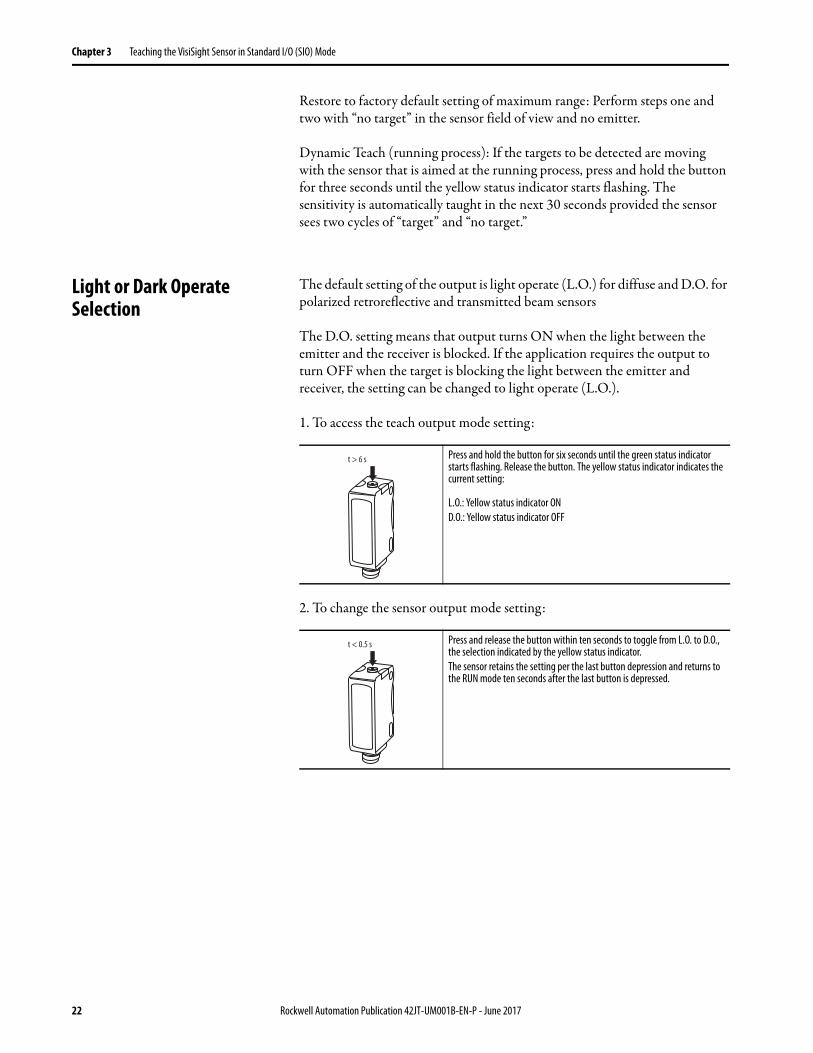
Light or Dark Operate Selection
The default setting of the output is light operate (L.O.) for diffuse and D.O. for polarized retroreflective and transmitted beam sensors
The D.O. setting means that output turns ON when the light between the emitter and the receiver is blocked. If the application requires the output to turn OFF when the target is blocking the light between the emitter and receiver, the setting can be changed to light operate (L.O.).
1. To access the teach output mode setting:
2. To change the sensor output mode setting:
Press and hold the button for six seconds until the green status indicator starts flashing. Release the button. The yellow status indicator indicates the current setting:
L.O.: Yellow status indicator OND.O.: Yellow status indicator OFF
Press and release the button within ten seconds to toggle from L.O. to D.O., the selection indicated by the yellow status indicator.The sensor retains the setting per the last button depression and returns to the RUN mode ten seconds after the last button is depressed.
t > 6 s
t < 0.5 s
22 Rockwell Automation Publication 42JT-UM001B-EN-P - June 2017
Teaching the VisiSight Sensor in Standard I/O (SIO) Mode Chapter 3
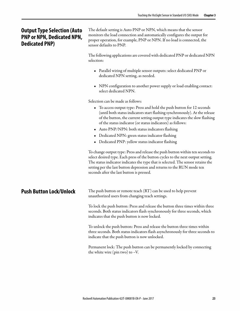
Output Type Selection (Auto PNP or NPN, Dedicated NPN, Dedicated PNP)
The default setting is Auto PNP or NPN, which means that the sensor monitors the load connection and automatically configures the output for proper operation, for example, PNP or NPN. If no load is connected, the sensor defaults to PNP.
The following applications are covered with dedicated PNP or dedicated NPN selection:
• Parallel wiring of multiple sensor outputs: select dedicated PNP or dedicated NPN setting, as needed.
• NPN configuration to another power supply or load enabling contact: select dedicated NPN.
Selection can be made as follows:• To access output type: Press and hold the push button for 12 seconds
(until both status indicators start flashing synchronously). At the release of the button, the current setting output type indicates the slow flashing of the status indicator (or status indicators) as follows:
• Auto PNP/NPN: both status indicators flashing• Dedicated NPN: green status indicator flashing• Dedicated PNP: yellow status indicator flashing
To change output type: Press and release the push button within ten seconds to select desired type. Each press of the button cycles to the next output setting. The status indicator indicates the type that is selected. The sensor retains the setting per the last button depression and returns to the RUN mode ten seconds after the last button is pressed.
Push Button Lock/Unlock The push button or remote teach (RT) can be used to help prevent unauthorized users from changing teach settings.
To lock the push button: Press and release the button three times within three seconds. Both status indicators flash synchronously for three seconds, which indicates that the push button is now locked.
To unlock the push button: Press and release the button three times within three seconds. Both status indicators flash asynchronously for three seconds to indicate that the push button is now unlocked.
Permanent lock: The push button can be permanently locked by connecting the white wire (pin two) to –V.
Rockwell Automation Publication 42JT-UM001B-EN-P - June 2017 23

Chapter 3 Teaching the VisiSight Sensor in Standard I/O (SIO) Mode
Remote Teach (RT) The sensor can be taught remotely via the white wire (pin two). Connection to +V acts the same as the button being pressed and no connection is the same as the button not being pressed. The sensor can be taught by following the same teach/timing sequence as used in the push button teach. For example, connect to the +V for more than three seconds to teach the “target,” disconnect from the +V; remove the target and connect to the +V for less than one second to teach “no target.” All push button functions can also be implemented via RT.
24 Rockwell Automation Publication 42JT-UM001B-EN-P - June 2017

Chapter 4
VisiSight Sensor with IO-Link Overview
Premier Integration Figure 16 - Typical IO-Link System Overview
The Studio 5000 Logix Designer® environment combines design and engineering elements in one interface, enabling users to access IO and configuration data across the Integrated Architecture system. Using a Rockwell Automation solution, provides a smooth, consistent integration of Allen-Bradley IO-Link enabled devices into the system.
To simplify the integration of the Rockwell Automation IO-Link devices to the Rockwell Automation architecture, there is an IO-Link Add-on Profile (AOP) available for the 1734-4IOL master module. The use of an AOP simplifies the setup of devices by providing the necessary fields in an organized manner that allows install and configuration of the systems in a quick and efficient manner.
36
Main patchcord 889M-R19RMMU-2
Passive Distribution Box 898D-P54PT-M12
Main patchcord889M-R11RMMU-2
Four separate colors
Passive Distribution Box 898D-P58PT-M12Up to any 8
SensorsSensorsSensors42JT 42EF 42JT 871TM 42JT 42EF 42JT 871TM
Patchcords (4 pcs.) 889D-F4ACDM-2
Rockwell Automation Publication 42JT-UM001B-EN-P - June 2017 25

Chapter 4 VisiSight Sensor with IO-Link Overview
Figure 17 - VisiSight IO-Link AOP Overview
VisiSight Sensor IO-Link Features
The VisiSight™ sensor communicates the following parameters via IO-Link.
Triggered
Communicates when a target has changed the state of the sensor upon detection, which performs the same operation as pin four (Output) while the sensor is operating in Standard IO (SIO) mode.
Margin Low Alarm
Helps minimize downtime by indicating when the sensor is about to fail due to insufficient light being reflected. This parameter performs the same operation as the sensor indication of insufficient light level when the sensor is operating in Standard I/O (SIO) mode.
Serialization
Helps machine OEMs to be sure that the sensors are installed in the proper location during commissioning at the customer site by providing a unique identification serial number to identify sensor mismatch.
26 Rockwell Automation Publication 42JT-UM001B-EN-P - June 2017
VisiSight Sensor with IO-Link Overview Chapter 4
Polarity
Changes the operation of the Triggered parameter, which performs the same function as teaching the Light and Dark Operate in Standard I/O (SIO) mode.
Enable or Disable Light Source: Turns the VisiSight sensor light source ON or OFF.
Lock and Unlock User Interface
Disables the push button interface, which helps prevent unauthorized users from changing sensor settings.
And these parameters, the VisiSight sensor allows you to perform remotely the following teach operations:
Standard Teach
Consists of two steps: teach the target (first condition) and teach “no target” (second condition). This method is recommended for most applications where there’s a considerable separation between the sensor and a background or if there’s no background present.
Precision Teach
Only requires one teach step to configure the sensor: teach target. This method is recommended for applications where minimal excess gain is required or for contrast applications.
Dynamic Teach
Is ideal for teaching the sensor during running applications. The sensor automatically detects the optimal gain settings to help ensure excellent reliability detection and operation.
Automatic Device Configuration (ADC)
Replacing damaged sensors is easy. Simply remove the old Allen-Bradley® sensor and connect the new one—the controller automatically sends the configuration to the new sensor.
Rockwell Automation Publication 42JT-UM001B-EN-P - June 2017 27

Chapter 4 VisiSight Sensor with IO-Link Overview
Figure 18 - Typical IO-Link System
Application Specific Name (ASN)
With numerous sensors on a machine with the same catalog number, the ASN parameter within each sensor makes it easy to identify the sensor during commissioning and the lifetime of the machine when collecting data. Name resides in the project and the sensor itself.
Figure 19 - Channel Configuration Overview
Tag Naming for I/O Data
Rockwell Automation system solutions provide tag names that are based on the Allen-Bradley sensor connected. I/O data is converted, formatted, and named based on the Allen-Bradley sensor applied. Reduces commissioning time by the OEM and reduces troubleshooting time by the end user when searching for sensor data. Consistent naming techniques used.
Figure 20 - Process Data
Allen-Bradley Controller
Allen-BradleyIO-Link Master
ADC
ADC
Sensor Configuration
Master Configuration VisiSight
sensor
28 Rockwell Automation Publication 42JT-UM001B-EN-P - June 2017

Chapter 5
Installing the VisiSight Sensor for IO-Link Mode
This chapter shows the physical hardware and software that is required to configure the VisiSight™ sensor through IO-Link and provides a simple guide to install the hardware.
Products required:
Hardware• VisiSight sensor• CompactLogix™ or ControlLogix® PLC Platform• POINT I/O™ Communications Interface: 1734-AENTR• POINT I/O IO-Link Master Module: 1734-4IOL• POINT I/O Terminal Base: 1734-TB• RJ45 network cable for EtherNet/IP connectivity:
1585J-M8TBJM-1M9x• 889D cordsets (optional): 889D-F4AC-5xx (IO-Link maximum
acceptable cable length is 20 m [65.6 ft])
Software• Studio 5000 environment, version 20 and higher• Sensor-specific IODD• 1734-4IOL IO-Link Add-on Profile (AOP)
Rockwell Automation Publication 42JT-UM001B-EN-P - June 2017 29

Chapter 5 Installing the VisiSight Sensor for IO-Link Mode
Example: Setting Up the Hardware
In this example, we are showing an Allen-Bradley® POINT I/O chassis with a 1734-AENTR adapter and a 1734-4IOL IO-Link master module in the first slot. The 1734-AENTR is communicating with a CompactLogix controller via EtherNet/IP.
Figure 21 - Hardware Setup
When adding a VisiSight sensor to the 1734-4IOL master module, complete the following steps:
1. Provide power to the 1734-AENTR adapter.
2. Set the node address on 1734-AENTR adapter.
3. Connect the 1734-AENTR to the Allen-Bradley® controller with the recommended RJ45 Ethernet cable.
4. Wire the sensor cable to the desired location on the IO-Link master (in this example, we are showing the sensor that is wired to the channel 0).
5. Connect the VisiSight sensor to the other end of the sensor cable.
1734-AENTR1734-4IOL
42JT
Patchcords (1 pc.) 889D-F4ACDM-2)
30 Rockwell Automation Publication 42JT-UM001B-EN-P - June 2017
Installing the VisiSight Sensor for IO-Link Mode Chapter 5
6. After connecting the sensor, you will need to create/open a project in Studio 5000® to establish communication with the Allen-Bradley controller that is being used and to add the 1734-AENTR adapter and 1734-4IOL IO-Link master module to Controller Organizer Tree (See Creating a Project on page 33 and See Configuring the IO-Link Master on page 37 for detailed instructions).
IMPORTANT Once the sensor adapter and the master module have been configured in the Controller Organizer Tree and the VisiSight sensor has been wired to the master module, the green indicator on the sensor can flash at a 1 Hz rate, which indicates that it, is operating in IO-Link mode. The green indicator that is associated with the channel that the sensor is wired into on the right-hand side of the master module can also pulse at a 1 Hz rate.
Rockwell Automation Publication 42JT-UM001B-EN-P - June 2017 31

Chapter 5 Installing the VisiSight Sensor for IO-Link Mode
Notes:
32 Rockwell Automation Publication 42JT-UM001B-EN-P - June 2017

Chapter 6
Creating a Project
To begin a new project in Studio 5000®, follow these steps.
If there’s an existing project within Studio 5000 with CompactLogix™ or ControlLogix® hardware that is installed and communicating online, go directly to See Configuring the IO-Link Master on page 37.
1. Double-click the Studio 5000 icon.
2. Click New Project.
3. To program the controller, select the controller that is used. In this example, it is the “1769 L24ER” CompactLogix™.
4. After selecting the controller, name the project and click “Next.” In this example, the project name is “Project42JT.”
Rockwell Automation Publication 42JT-UM001B-EN-P - June 2017 33
Chapter 6 Creating a Project
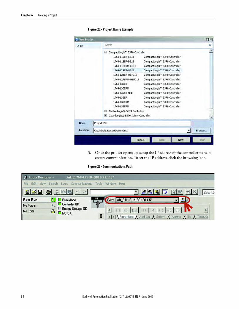
Figure 22 - Project Name Example
5. Once the project opens up, setup the IP address of the controller to help ensure communication. To set the IP address, click the browsing icon.
Figure 23 - Communications Path
34 Rockwell Automation Publication 42JT-UM001B-EN-P - June 2017
Creating a Project Chapter 6
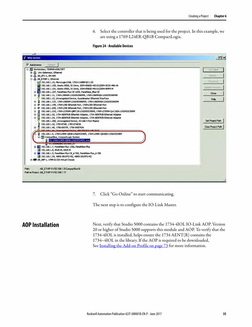
6. Select the controller that is being used for the project. In this example, we are using a 1769-L24ER-QB1B CompactLogix.
Figure 24 - Available Devices
7. Click “Go Online” to start communicating.
The next step is to configure the IO-Link Master.
AOP Installation Next, verify that Studio 5000 contains the 1734-4IOL IO-Link AOP. Version 20 or higher of Studio 5000 supports this module and AOP. To verify that the 1734-4IOL is installed, helps ensure the 1734 AENT(R) contains the 1734–4IOL in the library. If the AOP is required to be downloaded, See Installing the Add-on Profile on page 73 for more information.
Rockwell Automation Publication 42JT-UM001B-EN-P - June 2017 35

Chapter 6 Creating a Project
Notes:
36 Rockwell Automation Publication 42JT-UM001B-EN-P - June 2017
Chapter 7
Configuring the IO-Link Master
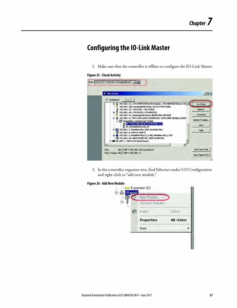
1. Make sure that the controller is offline to configure the IO-Link Master.
Figure 25 - Check Activity
2. In the controller organizer tree, find Ethernet under I/O Configuration and right-click to “add new module.”
Figure 26 - Add New Module
Rockwell Automation Publication 42JT-UM001B-EN-P - June 2017 37

Chapter 7 Configuring the IO-Link Master
3. The module window pops up and show the available modules. Select the “1734-AENTR, 1734 Ethernet adapter, two-port, twisted-pair media” and click Create.
Figure 27 - Select Module Type
4. Name the Ethernet adapter (in this example our adapter name is “adapter”), set the chassis size, check the module revision and set-up the adapter IP address. Click OK and then Close.
Figure 28 - Module Properties
5. The 1734 AENTR now appears in the Controller Organizer tree.
38 Rockwell Automation Publication 42JT-UM001B-EN-P - June 2017
Configuring the IO-Link Master Chapter 7
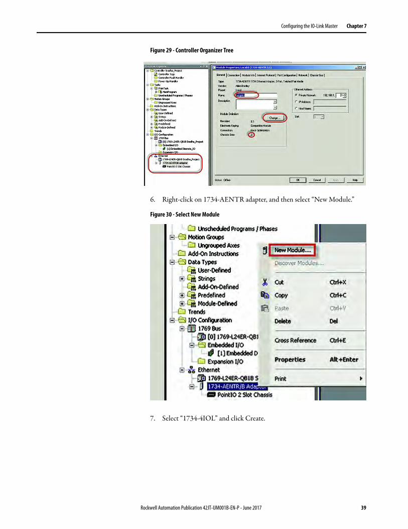
Figure 29 - Controller Organizer Tree
6. Right-click on 1734-AENTR adapter, and then select “New Module.”
Figure 30 - Select New Module
7. Select “1734-4IOL” and click Create.
Rockwell Automation Publication 42JT-UM001B-EN-P - June 2017 39

Chapter 7 Configuring the IO-Link Master
Figure 31 - Select Module Type
8. Another screen appears showing the IO-Link Configuration screen.
9. Name the IO-Link Master and click OK.
Figure 32 - Name the IO-Link Master
The VisiSight sensor can now be configured. To configure the sensor, a sensor-specific IODD (IO Device Description) file is required. The next steps shows how to register the IODD file.
40 Rockwell Automation Publication 42JT-UM001B-EN-P - June 2017

Chapter 8
Registering the VisiSight Sensor IODD
To initialize a sensor on an IO-Link Master, register the IODD of the sensor. The IO Device Description (IODD) files contain the information that is related to the sensor, integrated into the system environment.
By default, the IODDs are already located in the AOP Library.
If the IODD file for the VisiSight sensor cannot be located in the library, it can be downloaded from http://www.rockwellautomation.com/global/support/downloads.page. Once the IODD is registered, there’s no need to register the IODD again unless it is manually deleted from the Master Tree.
1. Double-click the 1734-4IOL in the Controller Organizer Tree.
Figure 33 - Controller Organizer Tree
2. Select the IO-Link configuration tab.
Figure 34 - IO-Link Configuration
Rockwell Automation Publication 42JT-UM001B-EN-P - June 2017 41
Chapter 8 Registering the VisiSight Sensor IODD
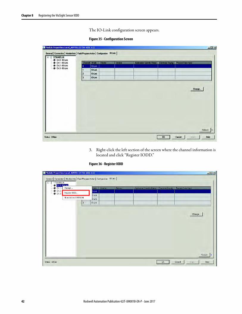
The IO-Link configuration screen appears.
Figure 35 - Configuration Screen
3. Right-click the left section of the screen where the channel information is located and click “Register IODD.”
Figure 36 - Register IODD
42 Rockwell Automation Publication 42JT-UM001B-EN-P - June 2017

Registering the VisiSight Sensor IODD Chapter 8
4. Select the IODD file that is needed for the sensor being configured and double-click.
Figure 37 - IODD Registrar
5. Then click “Exit.”
The IODD registration is complete.
Rockwell Automation Publication 42JT-UM001B-EN-P - June 2017 43

Chapter 8 Registering the VisiSight Sensor IODD
Notes:
44 Rockwell Automation Publication 42JT-UM001B-EN-P - June 2017

Chapter 9
Connecting the VisiSight Sensor to the IO-Link Master
Once the IODD file is registered, the sensor must be connected to the IO-Link master. The controller must always be off line to add a device to the IO-Link Master.
1. Right-click the channel number where the sensor is configured and click “Change.”
Figure 38 - Change Channel Configuration
2. Click … to select the appropriate sensor.
Figure 39 - Select IO-Link Device
Rockwell Automation Publication 42JT-UM001B-EN-P - June 2017 45

Chapter 9 Connecting the VisiSight Sensor to the IO-Link Master
3. Select the appropriate sensor and double-click or click “Create.”
Figure 40 - AOP Select Device View
4. Click “OK” to accept configuration.
Figure 41 - Main Controller View
5. Click “Go Online” to communicate. The following pages describe each tab of the 1734-4IOL AOP in detail and how to teach the sensor.
The following pages describe each tab of the 1734-4IOL AOP in detail and how to teach the sensor.
46 Rockwell Automation Publication 42JT-UM001B-EN-P - June 2017

Chapter 10
Exploring the VisiSight Sensor IO-Link Parameters
Overview The VisiSight sensor offers four different tabs to describe the sensor functionality and operation. These tabs are:
Common Tab
Provides general product information about the sensor specifications and IO-link IODD information.
Identification Tab
Provides the sensor catalog number, series letter, general product description including the current product firmware, and hardware revisions.
Parameter Tab
Displays and allows you to change the IO-Link parameters that are offered by the VisiSight™ sensor.
Diagnosis Tab
Offers the different teach functions available in the VisiSight sensor.
Rockwell Automation Publication 42JT-UM001B-EN-P - June 2017 47
Chapter 10 Exploring the VisiSight Sensor IO-Link Parameters
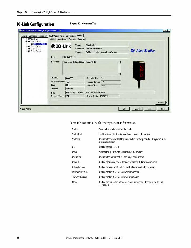
IO-Link Configuration Figure 42 - Common Tab
This tab contains the following sensor information.
Vendor Provides the vendor name of the product
Vendor Text Field that is used to describe additional product information
Vendor ID Describes the vendor ID of the manufacturer of the product as designated in the IO-Link consortium
URL Displays the vendor URL
Device Provides the specific catalog number of the product
Description Describes the sensor features and range performance
Device ID Displays the unique device ID as defined in the IO-Link specifications
IO-Link Revision Displays the current IO-Link version that is supported by the device
Hardware Revision Displays the latest sensor hardware information
Firmware Revision Displays the latest sensor firmware information
Bitrate Displays the supported bitrate for communications as defined in the IO-Link 1.1 standard
48 Rockwell Automation Publication 42JT-UM001B-EN-P - June 2017

Exploring the VisiSight Sensor IO-Link Parameters Chapter 10
Minimum Cycle Time
Figure 43 - Identification Tab
The Device Information shows us the Vendor Name, Product Name, Product Text, Product ID, and Serial Number of the exact sensor that is configured. These fields are automatically populated according to the sensor information. These fields are Read Only (RO).
The User Specific Information contains the Application Specific Name (ASN) where you can name the sensor with a unique text string for identification. The ASN allows a unique identity of each sensor. These fields can be custom (that is populated and is Read/Write).
SIO Mode Describes if the sensor is also designed to operate without an IO-Link connection
IODD Displays the complete file name of the IODD that is assigned to the product
Document Version Displays the version control for the IODD
Date of Creation Displays the IODD file was created.
Rockwell Automation Publication 42JT-UM001B-EN-P - June 2017 49

Chapter 10 Exploring the VisiSight Sensor IO-Link Parameters
Figure 44 - Parameter Tab
The parameter tab displays the sensor parameter settings and helps enable you to read data from the sensor or teach the sensor by writing new values.
The parameter section is divided into three sections: • Teach Operation• Operation Configuration, and • Sensor Configuration.
Teach-In Operation: In this section, it is possible to select the teach method that you would like to use and to evaluate and apply the teach settings after the sensor has been taught. All Teach-in Operation parameters are Write only (wo). To see detailed instructions on how to teach the VisiSight sensor using the 1734-4IOL AOP, refer to Chapter 11.
The VisiSight sensor has three distinct ways to teach the sensor: • Static Teach, • Precision Teach and Dynamic Teach, and • Local Teach.
.
Static Teach Is intended for applications where the target can be stopped or is stationary during the teach process. This process requires you to present the target and select the Show Target. Then you remove the target to press the Show Background button.
Precision Teach Is intended for applications where the precise setting of the distance is more critical. This teach method is also recommended for contrast applications.
Dynamic Teach Is ideal for applications that are continuously running and the target cannot be stopped to complete the teach process.
50 Rockwell Automation Publication 42JT-UM001B-EN-P - June 2017

Exploring the VisiSight Sensor IO-Link Parameters Chapter 10
Figure 45 - Diagnosis Tab
The Diagnosis Tab allows you to test some of the basic features of the sensor.
The diagnostic section is divided into three sections:
Validation and Authentication
Regardless of what teach method is selected, after initiating the teach commands, you must click the “Teach- Apply” to finalize the teach process.
Operation Configuration This section of the parameter tab allows you to read and change the sensor setpoint value and the output polarity for discrete output in SIO (Standard IO Mode) and IO-Link mode.
Setpoint 1 Value This parameter allows you to enter the threshold of when the sensor output turns ON. This parameter in combination with the Gain Select parameter present in the Sensor Configuration, helps the customer manually define the sensing range. This parameter automatically updates if the operator teaches the sensor using the local push button.
Polarity This parameter defines when the sensor discrete output or Triggered bit can be ON (1) or OFF (0). For light operate, the polarity selection must show “not inverted.” Therefore, when the status of the Triggered process data value is “1,” a target is present and the status of the Triggered process data value is “0,” a target is not present. For dark operate, the polarity selection must show “inverted.” Therefore, when the status of the Triggered process data value is “0,” a target is present and the status of the Triggered process value is “1,” a target is not present.
Sensor Configuration This section contains two parameters that allow you to turn the sensor light source and select the sensor gain depending on the application.
Light Source This parameter allows you to turn the sensor Light Source ON or OFF.
Gain Select This parameter defines the current gain level of the sensor to operate in high or low conditions. A high gain helps ensure that the sensor is able to detect targets with good reflectivity at longer ranges or verify that targets with low reflectivity are also detected at shorter ranges. This parameter is automatically updated when the sensor is taught using the push button and it’s linked to the setpoint value 1. This parameter cannot be changed via IO-Link as it impacts the sensing range of the device. (unless you have an understanding of the impact to your application of this change in the parameter)
Rockwell Automation Publication 42JT-UM001B-EN-P - June 2017 51

Chapter 10 Exploring the VisiSight Sensor IO-Link Parameters
• Device Access Locks, • Service Function, and• Communications Characteristics
Device Access Locks This section displays the Device Storage Lock and the user Interface Lock parameters. The Device Storage Lock is a read-only parameter that describes that data storage on the sensor cannot be locked and the Local User Interface Lock helps customers lock the push button on the VisiSight sensor.
Service Function This section only contains a write-only parameter that allows you to restore the sensor factory default settings. This parameter can be accessed through explicit messages as described in Chapter 11.
Communication Characteristics
In this section of the Diagnosis Tab, you can see read only (ro) values for the Minimum Cycle Time (response time of the sensor) and the Master Cycle Time (time that is used by the master to address the sensor) while in IO-Link mode. You can also visualize the IO-Link Revision of the sensor in this section.
52 Rockwell Automation Publication 42JT-UM001B-EN-P - June 2017

Exploring the VisiSight Sensor IO-Link Parameters Chapter 10
Manage Parameter Differences between IO-Link Devices and Controllers
The Add-on Profile has a Refresh button that updates the read-only parameters for all channels with IO-Link devices. It also performs a Correlation check of the read-write parameters in all connected IO-Link devices and in the controller. Differences in parameter values can happen when the device configuration is changed externally, such as through a device console during operation. If there are differences after running a Correlation check, you can choose to use the parameters that are currently in the connected IO-Link device or to use the parameters that are stored in the controller. The changes can be done on a per channel basis.
Before you proceed with this task, take note that the Refresh function:• Is only enabled in online mode.• Is performed initially when the Add-on Profile is launched in online
mode.
Figure 46 - Refresh
1. From the IO-Link tab on the working pane, click the Refresh button. If differences are detected in the RW values, a dialog box appears. The dialog box displays mismatched information per channel, including the parameters and the values present in the device and in the controller.
Figure 47 - Correlation Window
Rockwell Automation Publication 42JT-UM001B-EN-P - June 2017 53

Chapter 10 Exploring the VisiSight Sensor IO-Link Parameters
Communication errors (if applicable) are indicated in the dialog for each channel. A link becomes available for you to click to retry communication.
Figure 48 - Communication Errors
2. For each channel, select the checkbox for the corrective action:• Use Device Values: Uploads the parameter values that are read from the
connected IO-Link device to the project.• Use Project Values: Downloads the parameter values from the project to
the connected IO-Link device.
3. Click “OK.” If you click the “OK” button without fixing the errors, the read/write parameters of the affected channels are displayed.
Figure 49 - Parameter Tab
54 Rockwell Automation Publication 42JT-UM001B-EN-P - June 2017
Chapter 11
Teaching the VisiSight Sensor on IO-Link
The VisiSight™ sensor can be taught three distinct ways through the AOP. This chapter provides step-by-step instructions to teach the VisiSight sensor in each of these three methods.
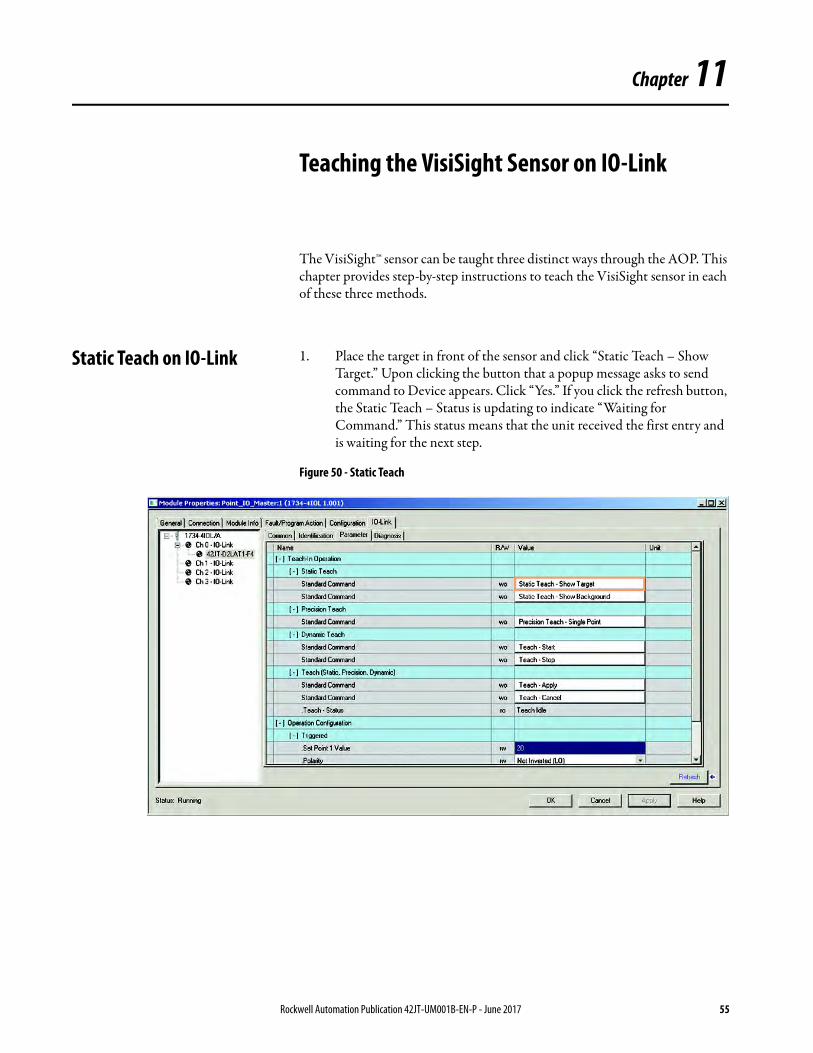
Static Teach on IO-Link 1. Place the target in front of the sensor and click “Static Teach – Show Target.” Upon clicking the button that a popup message asks to send command to Device appears. Click “Yes.” If you click the refresh button, the Static Teach – Status is updating to indicate “Waiting for Command.” This status means that the unit received the first entry and is waiting for the next step.
Figure 50 - Static Teach
Rockwell Automation Publication 42JT-UM001B-EN-P - June 2017 55

Chapter 11 Teaching the VisiSight Sensor on IO-Link
2. Remove the target from the sensor field of view and click “Static Teach – Show Background.” Upon clicking the button, a popup message asks “to send command to Device” appears. Click “Yes.”
Figure 51 - Static Teach — Show Background
3. Click the button “Teach-Apply.” Upon clicking the button, a popup message asks to send command to Device appears. Click “Yes.”
56 Rockwell Automation Publication 42JT-UM001B-EN-P - June 2017

Teaching the VisiSight Sensor on IO-Link Chapter 11
Precision Teach on IO-Link 1. Place the target in front of the sensor and click “Precision Teach – Single Point.” Upon clicking the button, a popup message asks to send command to Device appears. Click “Yes.” If you click the refresh button, the Static Teach – Status is updating to indicate “Waiting for Command.” This status means that the unit received the first entry and is waiting for the next step.
Figure 52 - Precision Teach — Single Point
2. Click the button “Teach-Apply.” Upon clicking the button, a popup message asks to send command to Device appears. Click “Yes.”
Rockwell Automation Publication 42JT-UM001B-EN-P - June 2017 57
Chapter 11 Teaching the VisiSight Sensor on IO-Link
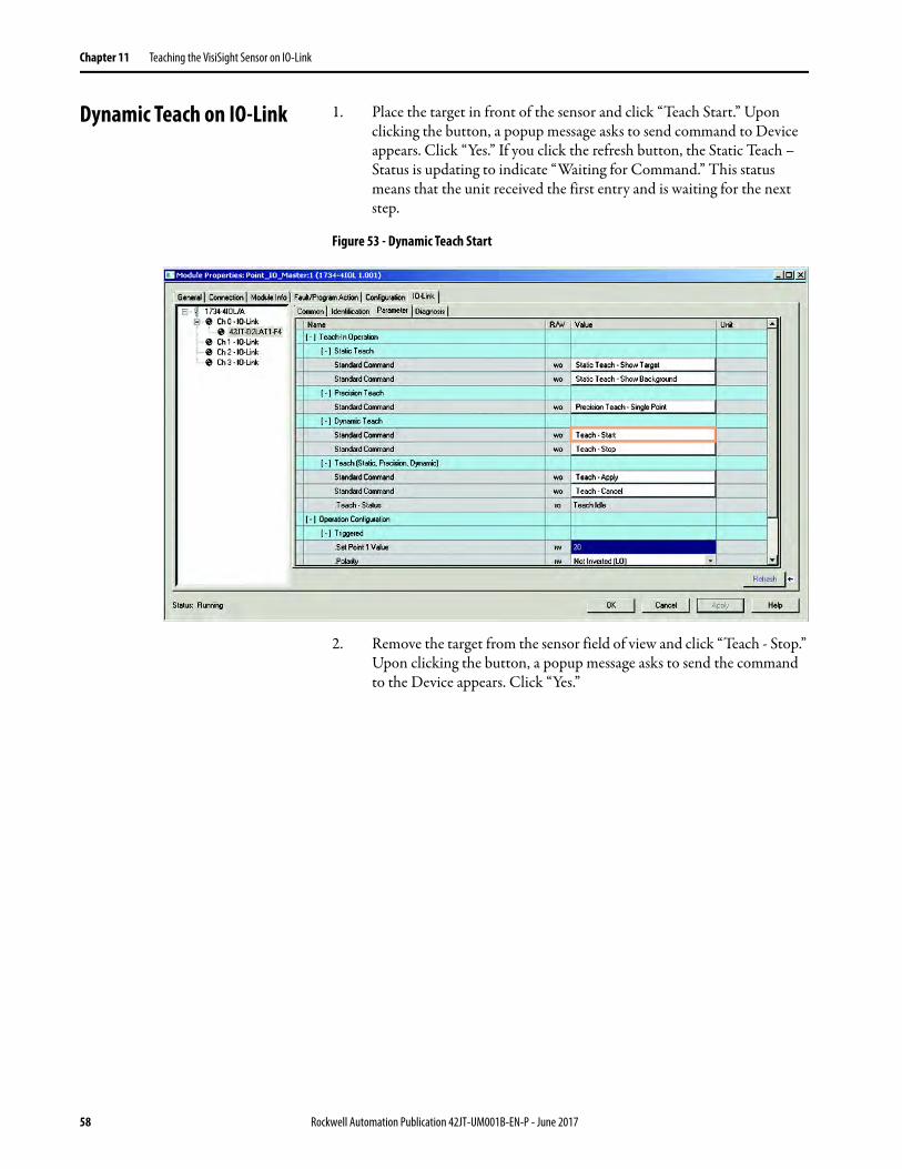
Dynamic Teach on IO-Link 1. Place the target in front of the sensor and click “Teach Start.” Upon clicking the button, a popup message asks to send command to Device appears. Click “Yes.” If you click the refresh button, the Static Teach – Status is updating to indicate “Waiting for Command.” This status means that the unit received the first entry and is waiting for the next step.
Figure 53 - Dynamic Teach Start
2. Remove the target from the sensor field of view and click “Teach - Stop.” Upon clicking the button, a popup message asks to send the command to the Device appears. Click “Yes.”
58 Rockwell Automation Publication 42JT-UM001B-EN-P - June 2017
Teaching the VisiSight Sensor on IO-Link Chapter 11
Figure 54 - Dynamic Teach Stop
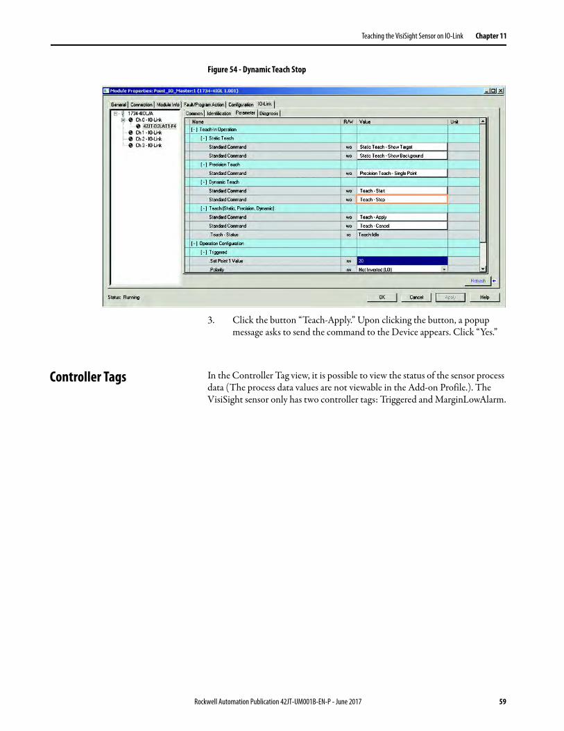
3. Click the button “Teach-Apply.” Upon clicking the button, a popup message asks to send the command to the Device appears. Click “Yes.”
Controller Tags In the Controller Tag view, it is possible to view the status of the sensor process data (The process data values are not viewable in the Add-on Profile.). The VisiSight sensor only has two controller tags: Triggered and MarginLowAlarm.
Rockwell Automation Publication 42JT-UM001B-EN-P - June 2017 59
Chapter 11 Teaching the VisiSight Sensor on IO-Link
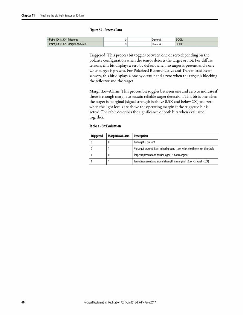
Figure 55 - Process Data
Triggered: This process bit toggles between one or zero depending on the polarity configuration when the sensor detects the target or not. For diffuse sensors, this bit displays a zero by default when no target is present and a one when target is present. For Polarized Retroreflective and Transmitted Beam sensors, this bit displays a one by default and a zero when the target is blocking the reflector and the target.
MarginLowAlarm: This process bit toggles between one and zero to indicate if there is enough margin to sustain reliable target detection. This bit is one when the target is marginal (signal strength is above 0.5X and below 2X) and zero when the light levels are above the operating margin if the triggered bit is active. The table describes the significance of both bits when evaluated together.
Table 3 - Bit Evaluation
Triggered MarginLowAlarm Description
0 0 No target is present
0 1 No target present, item in background is very close to the sensor threshold
1 0 Target is present and sensor signal is not marginal
1 1 Target is present and signal strength is marginal (0.5x < signal < 2X)
60 Rockwell Automation Publication 42JT-UM001B-EN-P - June 2017
Chapter 12
Installing the Sensor with Studio 5000
This chapter provides detailed instructions on installation of the VisiSight sensor using message instructions in Studio 5000®. The example code that is shown allows you to:
• Teach the sensor (Static Teach, Precision Teach, and Dynamic Teach)• Read sensor parameters using explicit messaging
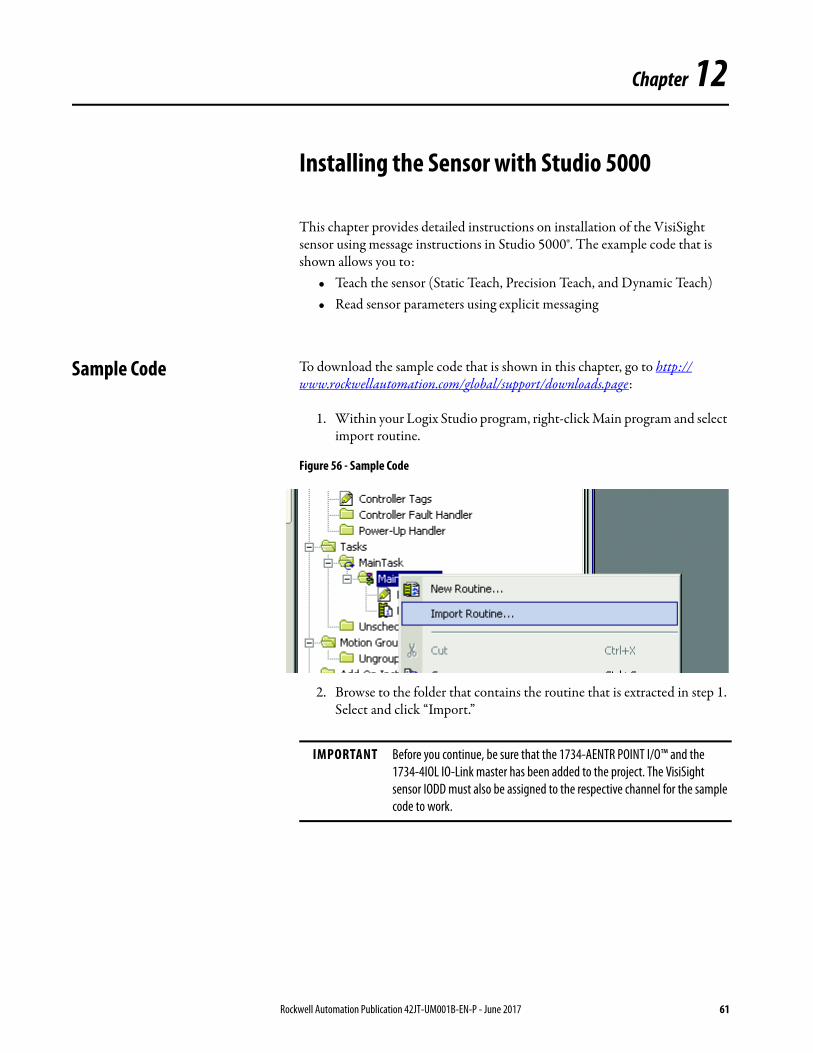
Sample Code To download the sample code that is shown in this chapter, go to http://www.rockwellautomation.com/global/support/downloads.page:
1. Within your Logix Studio program, right-click Main program and select import routine.
Figure 56 - Sample Code
2. Browse to the folder that contains the routine that is extracted in step 1. Select and click “Import.”
IMPORTANT Before you continue, be sure that the 1734-AENTR POINT I/O™ and the 1734-4IOL IO-Link master has been added to the project. The VisiSight sensor IODD must also be assigned to the respective channel for the sample code to work.
Rockwell Automation Publication 42JT-UM001B-EN-P - June 2017 61
Chapter 12 Installing the Sensor with Studio 5000
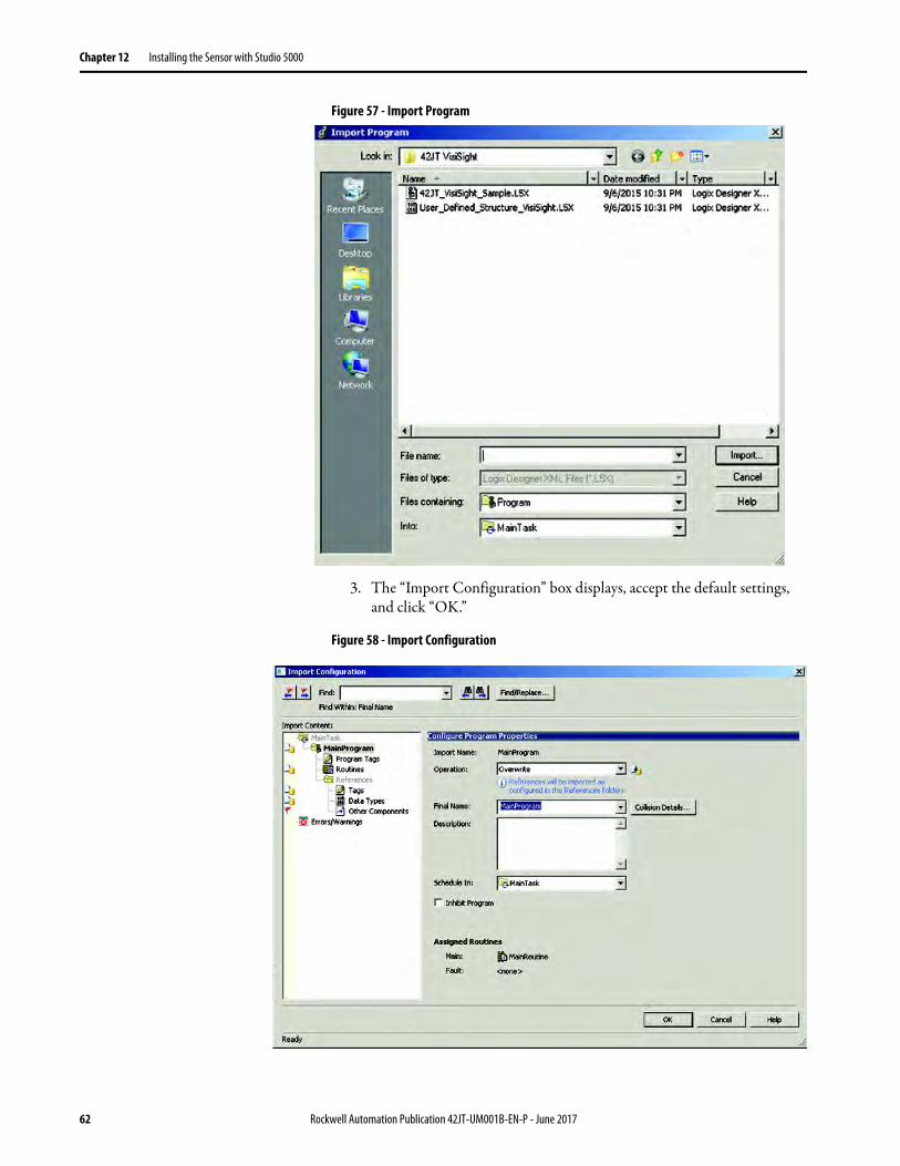
Figure 57 - Import Program
3. The “Import Configuration” box displays, accept the default settings, and click “OK.”
Figure 58 - Import Configuration
62 Rockwell Automation Publication 42JT-UM001B-EN-P - June 2017

Installing the Sensor with Studio 5000 Chapter 12
Sample Routines Figure 59 - Controller Organizer Overview
4. From the MainRoutine, create a rung of code that runs the subroutine Read_Vendor_Name. You can select any other subroutine as part of this example.
Figure 60 - Read Routine
5. Open the Read_Vendor_Name subroutine. On Rung 0 within the MSG Instruction, click the square button to open the message configuration.
Rockwell Automation Publication 42JT-UM001B-EN-P - June 2017 63

Chapter 12 Installing the Sensor with Studio 5000
Figure 61 - Explicit Message Routine
6. The Message configuration popup box is displayed. Click the “Communication” tab. Select the “Browse” button.
Figure 62 - Explicit Message Configuration
7. Browse the Ethernet Network to the 1734-AENTR and select the 1734-4IOL Master. Click “OK.”
Figure 63 - Message Path Browser
64 Rockwell Automation Publication 42JT-UM001B-EN-P - June 2017

Installing the Sensor with Studio 5000 Chapter 12
Notice that the path is now set to Master_1 in the communication path. Click “Apply” then “OK.”
Figure 64 - IO-Link Master
8. Repeat Step 6. For the message instructions about the MSG instruction use.
9. Verify that the routine is free of errors.
Figure 65 - Verify Routine
10. Download the program to the controller.
Figure 66 - Download the Controller
Rockwell Automation Publication 42JT-UM001B-EN-P - June 2017 65
Chapter 12 Installing the Sensor with Studio 5000
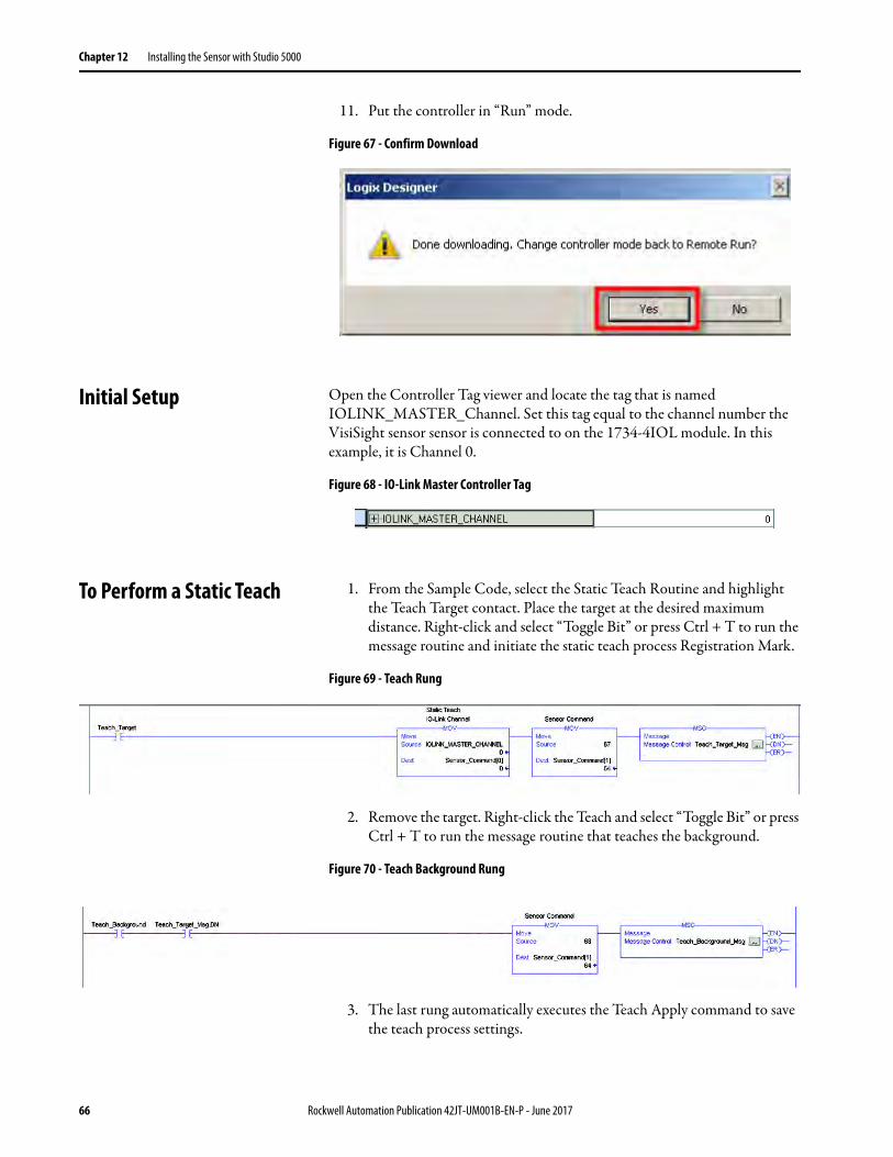
11. Put the controller in “Run” mode.
Figure 67 - Confirm Download
Initial Setup Open the Controller Tag viewer and locate the tag that is named IOLINK_MASTER_Channel. Set this tag equal to the channel number the VisiSight sensor sensor is connected to on the 1734-4IOL module. In this example, it is Channel 0.
Figure 68 - IO-Link Master Controller Tag
To Perform a Static Teach 1. From the Sample Code, select the Static Teach Routine and highlight the Teach Target contact. Place the target at the desired maximum distance. Right-click and select “Toggle Bit” or press Ctrl + T to run the message routine and initiate the static teach process Registration Mark.
Figure 69 - Teach Rung
2. Remove the target. Right-click the Teach and select “Toggle Bit” or press Ctrl + T to run the message routine that teaches the background.
Figure 70 - Teach Background Rung
3. The last rung automatically executes the Teach Apply command to save the teach process settings.
66 Rockwell Automation Publication 42JT-UM001B-EN-P - June 2017

Installing the Sensor with Studio 5000 Chapter 12
Figure 71 -
Figure 72 -
Precision Teach From the Sample Code, Select the Precision Teach Routine and highlight the Precision Teach contact. Place the target at the desired maximum distance. Right-click and select “Toggle Bit” or press Ctrl + T while highlighting the Precision Teach contact to run the message routine that initiates the precision teach process.
Figure 73 -
Upon successful transfer of the explicit message, the last rung automatically executes the Teach Apply command to save the teach process settings.
Figure 74 -
Rockwell Automation Publication 42JT-UM001B-EN-P - June 2017 67

Chapter 12 Installing the Sensor with Studio 5000
Precision Teach Sample Code
Figure 75 -
Dynamic Teach From the Sample Code, select the Dynamic Teach Routine and highlight the Start Dynamic Teach contact. While the machine is running (targets are passing in front of the sensor), right-click and select “Toggle Bit” or press Ctrl + T while highlighting the Precision Teach contact to run the message routine that initiates the precision teach process.
Figure 76 -
While the machine is running (targets are moving in front of the sensor), right-click the Stop Dynamic Teach contact and select “Toggle Bit” or press Ctrl + T to run the message routine that stops the dynamic teach process.
Figure 77 -
Upon successful transfer of the explicit message to stop the Teach Dynamic Teach, the last rung automatically executes the Teach Apply command to save the teach process settings.
Figure 78 -
68 Rockwell Automation Publication 42JT-UM001B-EN-P - June 2017
Installing the Sensor with Studio 5000 Chapter 12
Dynamic Teach Sample Code
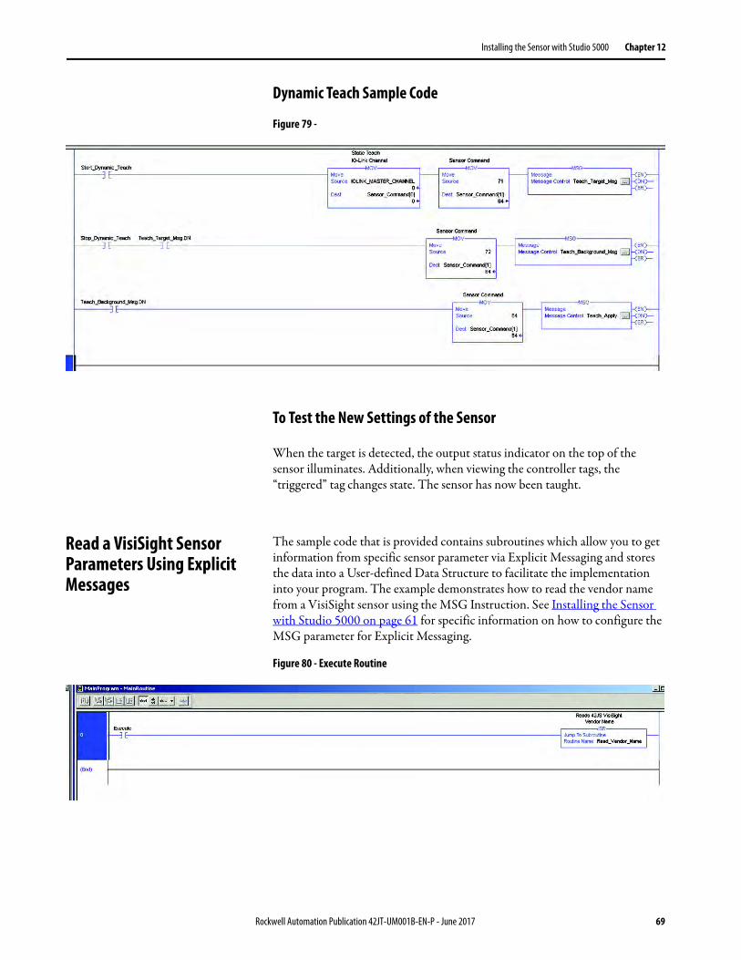
Figure 79 -
To Test the New Settings of the Sensor
When the target is detected, the output status indicator on the top of the sensor illuminates. Additionally, when viewing the controller tags, the “triggered” tag changes state. The sensor has now been taught.
Read a VisiSight Sensor Parameters Using Explicit Messages
The sample code that is provided contains subroutines which allow you to get information from specific sensor parameter via Explicit Messaging and stores the data into a User-defined Data Structure to facilitate the implementation into your program. The example demonstrates how to read the vendor name from a VisiSight sensor using the MSG Instruction. See Installing the Sensor with Studio 5000 on page 61 for specific information on how to configure the MSG parameter for Explicit Messaging.
Figure 80 - Execute Routine
Rockwell Automation Publication 42JT-UM001B-EN-P - June 2017 69
Chapter 12 Installing the Sensor with Studio 5000
Read Vendor Name Routine
Figure 81 -
Instructions MOV – Sets the IO-Link Master channel where the sensor is located
MSG – Sends the Explicit Message Service Request to Index 16 (‘Vendor Name’) as defined in Appendix B.
MOV – Sets the retrieved result word length to the VisiSight sensor user-defined data type
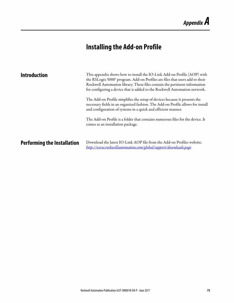
VisiSight Sensor User-defined Data Type Information
The VisiSight sensor user-defined data type helps you integrate the sensor parameters into their PLC program by providing the preformatted data types that make part of the sensor parameters.
Figure 82 - Controller Tags
70 Rockwell Automation Publication 42JT-UM001B-EN-P - June 2017

Chapter 13
Troubleshooting
This guide is meant to help resolve common issues that occur when installing the VisiSight™ sensor.
ChecklistError Cause Remedy
Power indicator does not light up
The power supply is switched off. Check to see if there’s a reason for it to be switched off (installation or maintenance work, and so on). Switch on the power supply if appropriate.
Power indicator does not light up
The 4-pin M12 plug is not connected to the connector on the sensor
Connect the 4-pin M12 plug to the sensor and tighten the cap nut by hand.
Power indicator does not light up
Wiring fault in the splitter or control cabinet.
Check the wiring carefully and repair any wiring faults.
“Operator indicator” does not light up
Supply cable to the sensor is damaged.
Replace the damaged cable.
No IO-Link connection to the device
The C/Q communication port on the sensor is not connected to the IO-Link master
Make sure that the C/Q communication port is connected to the IO-Link master.
Push button does not respond to user interface
Local operation has been deactivated.
Activate local operation.
Rockwell Automation Publication 42JT-UM001B-EN-P - June 2017 71

Chapter 13 Troubleshooting
Notes:
72 Rockwell Automation Publication 42JT-UM001B-EN-P - June 2017
Appendix A
Installing the Add-on Profile
Introduction This appendix shows how to install the IO-Link Add-on Profile (AOP) with the RSLogix 5000® program. Add-on Profiles are files that users add to their Rockwell Automation library. These files contain the pertinent information for configuring a device that is added to the Rockwell Automation network.
The Add-on Profile simplifies the setup of devices because it presents the necessary fields in an organized fashion. The Add-on Profile allows for install and configuration of systems in a quick and efficient manner.
The Add-on Profile is a folder that contains numerous files for the device. It comes as an installation package.
Performing the Installation Download the latest IO-Link AOP file from the Add-on Profiles website.http://www.rockwellautomation.com/global/support/downloads.page
Rockwell Automation Publication 42JT-UM001B-EN-P - June 2017 73

Appendix A Installing the Add-on Profile
Notes:
74 Rockwell Automation Publication 42JT-UM001B-EN-P - June 2017
Appendix B
Device Parameters
When using Explicit Messages to Read/Write parameter values from/to the VisiSight sensor, it’s important to know the Index Number, Data Type, and Size of the Data that is transmitted/received in the message. The Identification table provides this information for each of the Device Parameters.
Identification TabParameter Name Index Subindex
Hex (Dec)Access Default Value Data Type
(Length)Description
Hex Dec
Device Information
Vendor Name 0x10 16 0x00(0) RO Allen-Bradley STRING(64) Allen-Bradley®
Product Name 0x12 18 0x00(0) RO Product Catalog Number 42JT* STRING(64) Product Catalog Number
Product Text 0x14 20 0x00(0) RO Product Description STRING(64) Product Description
Product ID 0x13 19 0x00(0) RO Catalog Number and Series Letter
STRING(64) Product Catalog Number with Series Letter
Serial Number 0x15 21 0x00(0) RO Product Serial Number STRING(16) Serial Number (for example, 1442-000110)
User Specific Information
Application Specific Name 0x18 24 0x00(0) RO Blank STRING(32) Application Specific Name (User Input)
Revision Information
Hardware Revision 0x16 22 0x00(0) RO Hardware Revision 1 STRING(64) Hardware Revision
Firmware Revision 0x17 23 0x00(0) RO Firmware Revision 1.01 STRING(64) Firmware Revision
Rockwell Automation Publication 42JT-UM001B-EN-P - June 2017 75

Appendix B Device Parameters
Parameter TabParameter Name Index Subindex
Hex (Dec)Access Default Value Data Type
(Length)Allowed Values
Hex Dec
Teach-In Operation
Standard Command 0x02 2 0x00 WO Button = “Static Teach - Show Target”
67 UINTEGER(8) 67
Standard Command 0x02 2 0x00 WO Button = “Static Teach - Show Background”
68 UINTEGER(8) 68
Static Teach - Status 0x3B 59 0x01(1) RO Teach Idle UINTEGER(4) Teach Idle Waiting for Command
Teach Failed Not Successful
Precision Teach
Standard Command 0x02 2 0x00 WO Button = “Precision Teach - Single Point”
65 UINTEGER(8) 65
Static Teach - Status 0x3B 59 0x01(1) RO Teach Idle UINTEGER(4) Teach Idle Waiting for Command
Teach Failed Not Successful
Dynamic Teach
Standard Command 0x02 2 0x00 WO Button = “Teach - Start” 71 UINTEGER(8) 71
Standard Command 0x02 2 0x00 WO Button = “Teach - Stop” 72 UINTEGER(8) 72
Teach (Standard, Precision)
Standard Command 0x02 2 0x00 WO Button = “Teach - Apply” 64 UINTEGER(8) 64
Standard Command 0x02 2 0x00 WO Button = “Teach - Cancel” 79 UINTEGER(8) 79
Operation Configuration
Setpoint 1 Value 0x3C 60 0x01(1) RW 10: Highest Sensitivity1000: Lowest
Sensitivity
UINTEGER(8) 20...1000 (42JT-D2x)60…1000 (42JT-P2x)
0…25000 (42JT-B2LAT2x)0…28000 (42JT-B2LAT1x)0…31700 (42JT-B8LAT1x)
Polarity 0x3D 61 0x01(1) RW Depends on Sensing Mode 0: Inverted1: Not Inverted
UINTEGER(8) Not Inverted(Diffuse) Inverted (P-Retro,
TB-Receiver)
Sensor Configuration
Light Source 0x50 80 0x01(1) RW 1000 1: ON
Gain Select 0x53 83 0x01(1) RW Depends on Sensing Mode 0: LOW1: HIGH
BOOL Low Gain or High Gain. Parameter is only available in
Diffuse sensors
76 Rockwell Automation Publication 42JT-UM001B-EN-P - June 2017
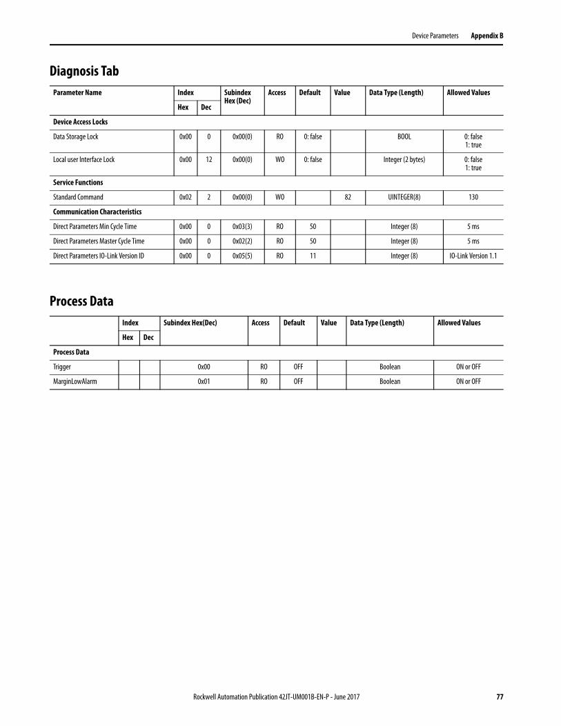
Device Parameters Appendix B
Diagnosis Tab
Process Data
Parameter Name Index Subindex Hex (Dec)
Access Default Value Data Type (Length) Allowed Values
Hex Dec
Device Access Locks
Data Storage Lock 0x00 0 0x00(0) RO 0: false BOOL 0: false1: true
Local user Interface Lock 0x00 12 0x00(0) WO 0: false Integer (2 bytes) 0: false1: true
Service Functions
Standard Command 0x02 2 0x00(0) WO 82 UINTEGER(8) 130
Communication Characteristics
Direct Parameters Min Cycle Time 0x00 0 0x03(3) RO 50 Integer (8) 5 ms
Direct Parameters Master Cycle Time 0x00 0 0x02(2) RO 50 Integer (8) 5 ms
Direct Parameters IO-Link Version ID 0x00 0 0x05(5) RO 11 Integer (8) IO-Link Version 1.1
Index Subindex Hex(Dec) Access Default Value Data Type (Length) Allowed Values
Hex Dec
Process Data
Trigger 0x00 RO OFF Boolean ON or OFF
MarginLowAlarm 0x01 RO OFF Boolean ON or OFF
Rockwell Automation Publication 42JT-UM001B-EN-P - June 2017 77

Appendix B Device Parameters
Notes:
78 Rockwell Automation Publication 42JT-UM001B-EN-P - June 2017
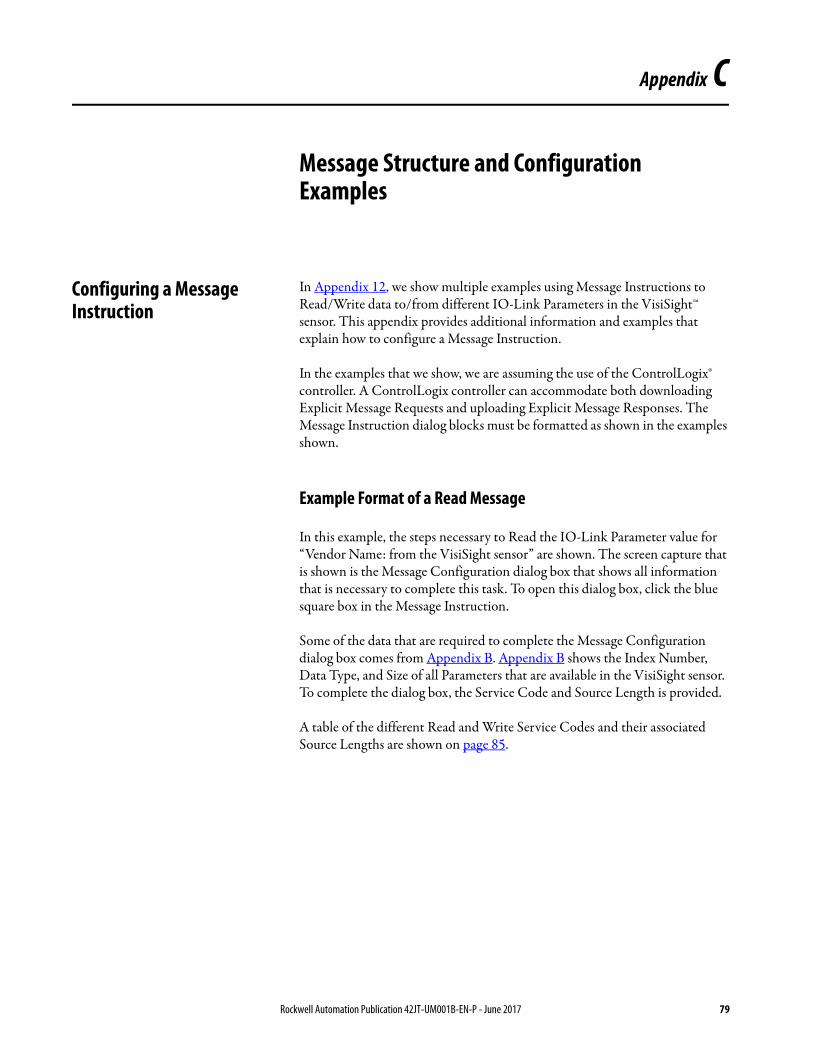
Appendix C
Message Structure and Configuration Examples
Configuring a Message Instruction
In Appendix 12, we show multiple examples using Message Instructions to Read/Write data to/from different IO-Link Parameters in the VisiSight™ sensor. This appendix provides additional information and examples that explain how to configure a Message Instruction.
In the examples that we show, we are assuming the use of the ControlLogix® controller. A ControlLogix controller can accommodate both downloading Explicit Message Requests and uploading Explicit Message Responses. The Message Instruction dialog blocks must be formatted as shown in the examples shown.
Example Format of a Read Message
In this example, the steps necessary to Read the IO-Link Parameter value for “Vendor Name: from the VisiSight sensor” are shown. The screen capture that is shown is the Message Configuration dialog box that shows all information that is necessary to complete this task. To open this dialog box, click the blue square box in the Message Instruction.
Some of the data that are required to complete the Message Configuration dialog box comes from Appendix B. Appendix B shows the Index Number, Data Type, and Size of all Parameters that are available in the VisiSight sensor. To complete the dialog box, the Service Code and Source Length is provided.
A table of the different Read and Write Service Codes and their associated Source Lengths are shown on page 85.
Rockwell Automation Publication 42JT-UM001B-EN-P - June 2017 79

Appendix C Message Structure and Configuration Examples
Figure 83 - Message Configuration
Table 4 identifies the data that are required to complete the Message Configuration dialog box to Read the “Vendor Name” from the VisiSight sensor.
Table 4 - Message Configuration
Box Description Value
1 Message Type
The message type is CIP Generic. CIP Generic
2 Service Type
The service type is Custom. Custom
3 Service Code
Established from Service Code Table. 4D
4 Class
The class is 3a3. 3a3
5 Instance
Established from Appendix A. Identifies the Index for the Parameter being read. 16
6 Attribute
The Attribute value is 0. 0
7 Source Element
Contains the name of the tag of the channel number to be read. Write_Assembly[0]
8 Source Length
This box contains the number of bytes of service data to be sent or received in message. Defined in Data Structure Tables.
1 byte
9 Destination Element
First element of the destination Array. Read_Assembly[0]
80 Rockwell Automation Publication 42JT-UM001B-EN-P - June 2017
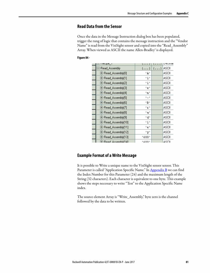
Message Structure and Configuration Examples Appendix C
Read Data from the Sensor
Once the data in the Message Instruction dialog box has been populated, trigger the rung of logic that contains the message instruction and the “Vendor Name” is read from the VisiSight sensor and copied into the “Read_Assembly” Array. When viewed as ASCII the name Allen-Bradley® is displayed.
Figure 84 -
Example Format of a Write Message
It is possible to Write a unique name to the VisiSight sensor sensor. This Parameter is called “Application Specific Name.” In Appendix B we can find the Index Number for this Parameter (24) and the maximum length of the String (32 characters). Each character is equivalent to one byte. This example shows the steps necessary to write “Test” to the Application Specific Name index.
The source element Array is “Write_Assembly,” byte zero is the channel followed by the data to be written.
Rockwell Automation Publication 42JT-UM001B-EN-P - June 2017 81
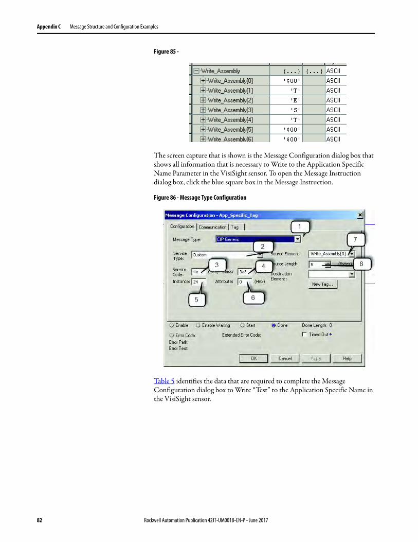
Appendix C Message Structure and Configuration Examples
Figure 85 -
The screen capture that is shown is the Message Configuration dialog box that shows all information that is necessary to Write to the Application Specific Name Parameter in the VisiSight sensor. To open the Message Instruction dialog box, click the blue square box in the Message Instruction.
Figure 86 - Message Type Configuration
Table 5 identifies the data that are required to complete the Message Configuration dialog box to Write “Test” to the Application Specific Name in the VisiSight sensor.
82 Rockwell Automation Publication 42JT-UM001B-EN-P - June 2017

Message Structure and Configuration Examples Appendix C
Table 5 - Message Configuration
Validation of Write
Once the data in the Message Instruction dialog box has been populated; trigger the rung of logic that contains the message instruction and “Test” is written from the “Write_Assembly” to the Application-specific Name Parameter Index in the VisiSight sensor.
The data is validated either by reading the value of Index 24 in the sensor or by viewing the 1734-4IOL configuration. To view the configuration of the 1734-4IOL follow these steps:
1. Click the 1734-4IOL in the IO Configuration.
2. A popup box is displayed, which advises that changes within the sensor have been detected. Expand the settings and to see that the Application Specific Name has changed to Test.
Box Description Value
1 Message Type
The message type is CIP Generic. CIP Generic
2 Service Type
The service type is Custom. Custom
3 Service Code
Established from Service Code Table. 4E
4 Class
The class is 3a3. 3a3
5 Instance
Established from Appendix A. Identifies the Index for the Parameter being read.
24
6 Attribute
The Attribute value is 0. 0
7 Source Element
Contains the name of the first tag of the data array to be written. Write_Assembly[0]
8 Source Length
This box contains the number of bytes of service data to be sent or received in a message. Defined in Data Structure Tables.
5 bytes
9 Destination Element
N/A N/A
Rockwell Automation Publication 42JT-UM001B-EN-P - June 2017 83
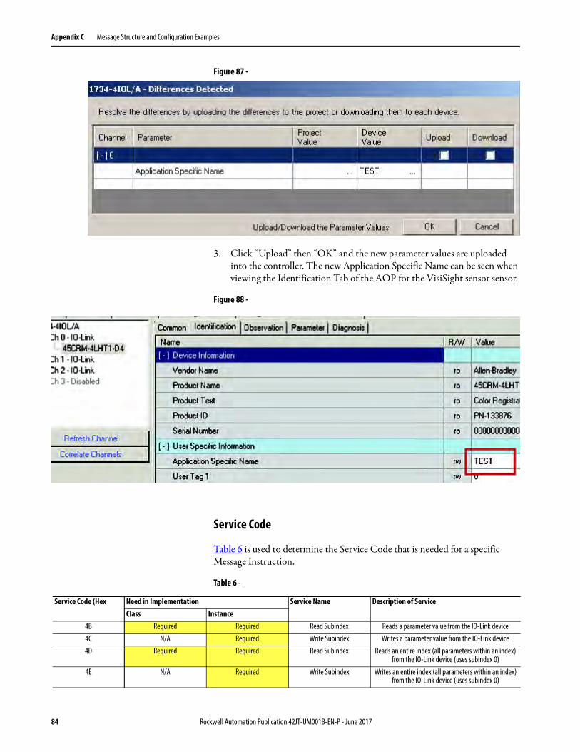
Appendix C Message Structure and Configuration Examples
Figure 87 -
3. Click “Upload” then “OK” and the new parameter values are uploaded into the controller. The new Application Specific Name can be seen when viewing the Identification Tab of the AOP for the VisiSight sensor sensor.
Figure 88 -
Service Code
Table 6 is used to determine the Service Code that is needed for a specific Message Instruction.
Table 6 -
Service Code (Hex Need in Implementation Service Name Description of ServiceClass Instance
4B Required Required Read Subindex Reads a parameter value from the IO-Link device4C N/A Required Write Subindex Writes a parameter value from the IO-Link device4D Required Required Read Subindex Reads an entire index (all parameters within an index)
from the IO-Link device (uses subindex 0)4E N/A Required Write Subindex Writes an entire index (all parameters within an index)
from the IO-Link device (uses subindex 0)
84 Rockwell Automation Publication 42JT-UM001B-EN-P - June 2017
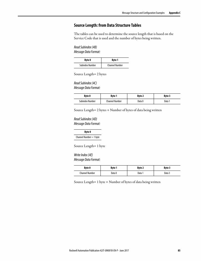
Message Structure and Configuration Examples Appendix C
Source Length: from Data Structure Tables
The tables can be used to determine the source length that is based on the Service Code that is used and the number of bytes being written.
Read Subindex (4B)Message Data Format:
Source Length= 2 bytes
Read Subindex (4C)Message Data Format:
Source Length= 2 bytes + Number of bytes of data being written
Read Subindex (4D)Message Data Format:
Source Length= 1 byte
Write Index (4E)Message Data Format:
Source Length= 1 byte + Number of bytes of data being written
Byte 0 Byte 1
Subindex Number Channel Number
Byte 0 Byte 1 Byte 2 Byte 3
Subindex Number Channel Number Data 0 Data 1
Byte 0
Channel Number = 1 byte
Byte 0 Byte 1 Byte 2 Byte 3
Channel Number Data 0 Data 1 Data 3
Rockwell Automation Publication 42JT-UM001B-EN-P - June 2017 85

Appendix C Message Structure and Configuration Examples
Notes:
86 Rockwell Automation Publication 42JT-UM001B-EN-P - June 2017

Appendix D
Error Codes and Events
When an event occurs, the device signals the presence of the event to the master. The master then reads out the event. Events can be error messages and warnings/maintenance data. Error messages are transmitted from the device to the controller via the IO-Link master. The transmission of device parameters or events occurs independently from the cyclic transmission of process data.
Error Codes
Event Codes
Error Codes Code
Index not available 0x8011
Subindex not available 0x8012
Service temporarily not available 0x8022
Access denied 0x8023
Parameter value out of range 0x8030
Parameter length overrun 0x8033
Parameter length underruns 0x8034
Invalid parameter set 0x8040
Event Codes Code
Data storage - Upload request 0xFF91
Rockwell Automation Publication 42JT-UM001B-EN-P - June 2017 87

Appendix D Error Codes and Events
Notes:
88 Rockwell Automation Publication 42JT-UM001B-EN-P - June 2017

Notes:
89 Rockwell Automation Publication 42JT-UM001B-EN-P - June 2017

Notes:
90 Rockwell Automation Publication 42JT-UM001B-EN-P - June 2017

Notes:
91 Rockwell Automation Publication 42JT-UM001B-EN-P - June 2017
Publication 42JT-UM001B-EN-P - June 2017Supersedes Publication 42JT-UM001A-EN-P - September 2015 Copyright © 2017 Rockwell Automation, Inc. All rights reserved. Printed in the U.S.A.
Rockwell Automation SupportUse the following resources to access support information.
Documentation FeedbackYour comments will help us serve your documentation needs better. If you have any suggestions on how to improve this document, complete the How Are We Doing? form at http://literature.rockwellautomation.com/idc/groups/literature/documents/du/ra-du002_-en-e.pdf.
Technical Support Center Knowledgebase Articles, How-to Videos, FAQs, Chat, User Forums, and Product Notification Updates. https://rockwellautomation.custhelp.com/
Local Technical Support Phone Numbers Locate the phone number for your country. http://www.rockwellautomation.com/global/support/get-support-now.page
Direct Dial Codes Find the Direct Dial Code for your product. Use the code to route your call directly to a technical support engineer. http://www.rockwellautomation.com/global/support/direct-dial.page
Literature Library Installation Instructions, Manuals, Brochures, and Technical Data. http://www.rockwellautomation.com/global/literature-library/overview.page
Product Compatibility and Download Center (PCDC)
Get help determining how products interact, check features and capabilities, and find associated firmware. http://www.rockwellautomation.com/global/support/pcdc.page
.
Rockwell Otomasyon Ticaret A.Ş., Kar Plaza İş Merkezi E Blok Kat:6 34752 İçerenköy, İstanbul, Tel: +90 (216) 5698400
Rockwell Automation maintains current product environmental information on its website at http://www.rockwellautomation.com/rockwellautomation/about-us/sustainability-ethics/product-environmental-compliance.page.
Allen-Bradley, Rockwell Software, and Rockwell Automation are trademarks of Rockwell Automation, Inc.
Trademarks not belonging to Rockwell Automation are property of their respective companies.