VisionPRO Wi-Fi Model TH8320WF - Honeywell · VisionPRO® Wi-Fi Model TH8320WF Touch-screen...
32
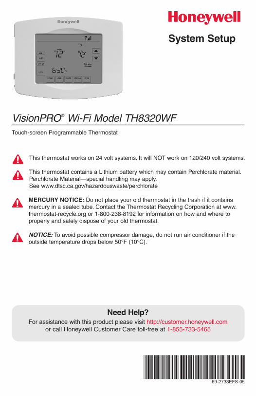
VisionPRO ® Wi-Fi Model TH8320WF Touch-screen Programmable Thermostat System Setup Need Help? For assistance with this product please visit http://customer.honeywell.com or call Honeywell Customer Care toll-free at 1-855-733-5465 This thermostat works on 24 volt systems. It will NOT work on 120/240 volt systems. This thermostat contains a Lithium battery which may contain Perchlorate material. Perchlorate Material—special handling may apply. See www.dtsc.ca.gov/hazardouswaste/perchlorate MERCURY NOTICE: Do not place your old thermostat in the trash if it contains mercury in a sealed tube. Contact the Thermostat Recycling Corporation at www. thermostat-recycle.org or 1-800-238-8192 for information on how and where to properly and safely dispose of your old thermostat. NOTICE: To avoid possible compressor damage, do not run air conditioner if the outside temperature drops below 50°F (10°C). 69-2733EFS-05
Transcript of VisionPRO Wi-Fi Model TH8320WF - Honeywell · VisionPRO® Wi-Fi Model TH8320WF Touch-screen...
VisionPRO® Wi-Fi Model TH8320WFTouch-screen Programmable Thermostat
System Setup
Need Help?For assistance with this product please visit http://customer.honeywell.com
or call Honeywell Customer Care toll-free at 1-855-733-5465
This thermostat works on 24 volt systems. It will NOT work on 120/240 volt systems.
This thermostat contains a Lithium battery which may contain Perchlorate material.Perchlorate Material—special handling may apply.See www.dtsc.ca.gov/hazardouswaste/perchlorate
MERCURY NOTICE: Do not place your old thermostat in the trash if it contains mercury in a sealed tube. Contact the Thermostat Recycling Corporation at www.thermostat-recycle.org or 1-800-238-8192 for information on how and where to properly and safely dispose of your old thermostat.
NOTICE: To avoid possible compressor damage, do not run air conditioner if the outside temperature drops below 50°F (10°C).
69-2733EFS-05

69-2733EFS—05 2
MCR29481
+
+ +
MCR29480
1 Separate wallplate from thermostat.
2 Mount wallplate as shown below.
Grasp top and bottom of wallplate and pull to remove from thermostat.
Drill 3/16” holes for drywall. Drill 7/32” holes for plaster.
Wall anchors
Wire hole Mounting screws
Wallplate installation
3 69-2733EFS—05
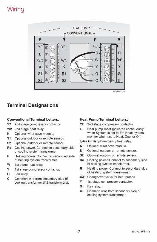
Y2
W2
K
S1
S2
RC
R
W
Y
G
C
RC
R
O/B
Y
G
C
HEAT PUMP
CONVENTIONAL
Y2
L
E/AUX
K
S1
S2
MCR34051A
Conventional Terminal Letters:Y2 2nd stage compressor contactor.
W2 2nd stage heat relay.
K Optional wirer save module.
S1 Optional outdoor or remote sensor.
S2 Optional outdoor or remote sensor.
Rc Cooling power. Connect to secondary side of cooling system transformer.
R Heating power. Connect to secondary side of heating system transformer.
W 1st stage heat relay.
Y 1st stage compressor contactor.
G Fan relay.
C Common wire from secondary side of cooling transformer (if 2 transformers).
Heat Pump Terminal Letters:Y2 2nd stage compressor contactor.
L Heat pump reset (powered continuously when System is set to Em Heat; system monitor when set to Heat, Cool or Off).
E/Aux Auxiliary/Emergency heat relay.
K Optional wirer save module.
S1 Optional outdoor or remote sensor.
S2 Optional outdoor or remote sensor.
Rc Cooling power. Connect to secondary side of cooling system transformer.
R Heating power. Connect to secondary side of heating system transformer.
O/B Changeover valve for heat pumps.
Y 1st stage compressor contactor.
G Fan relay.
C Common wire from secondary side of cooling system transformer.
Terminal Designations
Wiring
69-2733EFS—05 4
DONE
TUE
15
62012
DONE
TUE
PM1:00
MCR29485
MCR29484
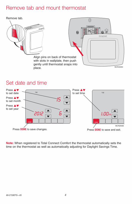
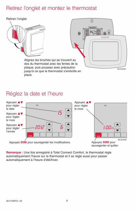
Remove tab.
Align pins on back of thermostat with slots in wallplate, then push gently until thermostat snaps into place.
Note: When registered to Total Connect Comfort the thermostat automatically sets the time on the thermostat as well as automatically adjusting for Daylight Savings Time.
Remove tab and mount thermostat
Set date and timePress st to set time
Press st to set date
Press st to set month
Press st to set year
Press DONE to save changes. Press DONE to save and exit.
5 69-2733EFS—05
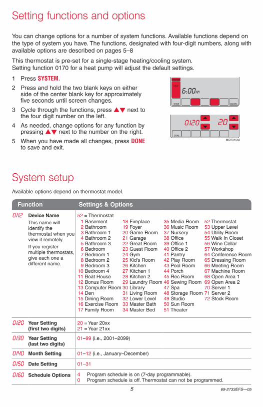
Setting functions and options
You can change options for a number of system functions. Available functions depend on the type of system you have. The functions, designated with four-digit numbers, along with available options are described on pages 5–8
This thermostat is pre-set for a single-stage heating/cooling system. Setting function 0170 for a heat pump will adjust the default settings.
DONE CANCEL
TUE
aM6:00
SYSTEM
HEAT
DONE
0120 20
MCR31563
1 Press SYSTEM.
2 Press and hold the two blank keys on either side of the center blank key for approximately five seconds until screen changes.
3 Cycle through the functions, press st next to the four digit number on the left.
4 As needed, change options for any function by pressing st next to the number on the right.
5 When you have made all changes, press DONE to save and exit.
System setupAvailable options depend on thermostat model.
Function Settings & Options
0112 Device NameThis name will identify the thermostat when you view it remotely.If you register multiple thermostats, give each one a different name.
52 = Thermostat 1 Basement 18 Fireplace 35 Media Room 52 Thermostat 2 Bathroom 19 Foyer 36 Music Room 53 Upper Level 3 Bathroom 1 20 Game Room 37 Nursery 54 Utility Room 4 Bathroom 2 21 Garage 38 Office 55 Walk In Closet 5 Bathroom 3 22 Great Room 39 Office 1 56 Wine Cellar 6 Bedroom 23 Guest Room 40 Office 2 57 Workshop 7 Bedroom 1 24 Gym 41 Pantry 64 Conference Room 8 Bedroom 2 25 Kid's Room 42 Play Room 65 Dressing Room 9 Bedroom 3 26 Kitchen 43 Pool Room 66 Meeting Room10 Bedroom 4 27 Kitchen 1 44 Porch 67 Machine Room11 Boat House 28 Kitchen 2 45 Rec Room 68 Open Area 112 Bonus Room 29 Laundry Room 46 Sewing Room 69 Open Area 213 Computer Room 30 Library 47 Spa 70 Server 114 Den 31 Living Room 48 Storage Room 71 Server 215 Dining Room 32 Lower Level 49 Studio 72 Stock Room16 Exercise Room 33 Master Bath 50 Sun Room17 Family Room 34 Master Bed 51 Theater
0120 Year Setting (first two digits)
20 = Year 20xx 21 = Year 21xx
0130 Year Setting (last two digits)
01–99 (i.e., 2001–2099)
0140 Month Setting 01–12 (i.e., January–December)
0150 Date Setting 01–31
0160 Schedule Options 4 Program schedule is on (7-day programmable).0 Program schedule is off. Thermostat can not be programmed.
69-2733EFS—05 6
System setup
Function Settings & Options
0165 Restore Schedule Defaults
0 Continue using programmed schedule.1 Restore thermostat program to energy saving settings
0170 Select System TypeIf you are not sure of your heating/cooling system type or have other questions, go to wifithermostat.com
1 Heat/cool: Gas, oil or electric heating with central air conditioning.2 Heat pump: Heat pump without backup or auxiliary heat.3 Heat only without fan: Gas, oil or electric heat without central air
conditioning.4 Heat only with fan: Gas, oil or electric heat without central air
conditioning.5 Heat only (no fan): Gas, oil or hot water heat without central air
conditioning.6 Cool only: Central air conditioning only.7 Heat pump: Heat pump with backup or auxiliary heating.8 Heat/Cool Multiple stages: 2 heat stages (wires on W and W2), 2
cooling stages (wires on Y and Y2).9 Heat/Cool Multiple stages: 2 heat stages (wires on W and W2), 1
cooling stage (wire on Y).10 Heat/Cool Multiple stages: 1 heat stage (wire on W), 2 cooling stages
(wires on Y and Y2).11 Heat pump multiple stages: 2 heat stages (wires on W and W2),
2 cooling stages (wires on Y and Y2) (no aux. heat).12 Heat pump multiple stages: 3 heat stages (wires on W, W2, and Aux),
2 cooling stages (wires on Y and Y2) (with aux heat).
0173 Heat Pump Type 0 Air to air heat pump1 Geothermal heat pump
0180 Heating Fan Control
0 Gas or oil heat: Use this setting if you have a gas or oil heating system (system controls fan operation).
1 Electric heat: Use this setting if you have an electric heating system (thermostat controls fan operation).
0190 Heat Pump Changeover Valve (for heat pumps only)
0 Cooling changeover valve: Use this setting if you connected a wire labeled “O” to the O/B terminal.
1 Heating changeover valve: Use this setting if you connected a wire labeled “B” to the O/B terminal.
0200 Back-up Heat Source
0 Electric1 Fossil fuel
0210 External Fossil Fuel Kit
0 No1 Yes
0220 1st stage compres-sor cycle rate
3 Recommended for most compressors [Other options: 1, 2, 4, 5 or 6 CPH]
0230 2nd stage com-pressor cycle rate
0240 Heating Cycle Rate
5 Gas or oil furnace: Standard gas/oil furnace (less than 90% efficiency).9 Electric furnace: Electric heating systems.3 Hot water or high-efficiency furnace: Hot water system or gas furnace
(more than 90% efficiency).1 Gas/oil steam or gravity system: Steam or gravity heat systems. [Other options: 2,4,6,7,8,10,11,12]
0250 Heating Cycle Rate Stage 2
0260 Heating Cycle Rate Stage 3
0280 Backlight 0 Backlight off, then on for approximately 8 seconds after keypress.1 Backlight always on low intensity, full bright after keypress.
7 69-2733EFS—05
System setup
Function Settings & Options
0300 Manual/Auto Changeover
0 Manual changeover (Heat/Cool/Off).1 Automatic changeover (Heat/Cool/Auto/Off). Automatically turns on Heat
or Cool based on room temperature. Note: System maintains minimum 3°F difference between heat and cool settings.
0310 Auto changeover deadband
3 Heat/cool temperature 3°F apart (1.5°C) [Other options: 2-9 (2°F to 9°F/1°C to 5°C)])
0320 Temperature For-mat (°F/°C)
0 Fahrenheit1 Celsius
0330 Automatic Daylight Saving Time Ad-justment
0 Off1 On
0340 Remote Temp Sensor
0 None1 Outdoor for Display2 Outdoor for Control3 Remote Indoor
0346 Dual Fuel Heat Pump Upstage to Furnace Timer
0 Off0.5 30 minutes1 1 hour1.5 1.5 hours2 2 hours3 3 hours4 4 hours
5 5 hours6 6 hours8 8 hours10 10 hours12 12 hours14 14 hours16 16 hours
0347 Droop Temperature (Steady State)
2 °F (1.0 °C) [Other options: displayed in °F or °C]
0349 Backup Heat Manual Droop Tem-perature
0 Comfort (Off) 1 Economy
0350 Heat Pump Com-pressor Lockout
0 Off [Other options: displayed in °F or °C]
0360 Heat Pump Aux Lockout
0 None [Other options: displayed in °F or °C]
0500 Filter Change ReminderThe reminder appears after selected number of days run time not actual time.
0 Off (no reminder)1 Reminder after 10-day run time (about 1 calendar month)2 Reminder after 30-day run time (about 3 calendar months)3 Reminder after 60-day run time (about 6 calendar months)4 Reminder after 90-day run time (about 9 calendar months)5 Reminder after 120-day run time (about 1 calendar year)6 Reminder after 180-day run time (about 18 calendar months)7 Reminder after 270-day run time (about 2 calendar years)8 Reminder after 365-day run time (about 3 calendar years)
0502 Furnace filter for Run time
0 Counts both heat and cool1 Counts cool only
0510 Humidifier Pad Replacement Re-minder
0 Disabled1 30-day run time (about 3 months)2 60-day run time (about 6 months)3 90-day run time (about 9 months)
0520 UV Lamp Replace-ment Reminder
0 Disabled1 365 days2 730 days
69-2733EFS—05 8
System setup
Function Settings & Options
0530 Adaptive Intelligent Recovery
1 On0 Off
0580 Compressor protection
5 5 minute compressor off time [Other options: 0, 1, 2, 3 or 4-minute off time]
0600 Heat temperature range stop
90 Max. heat temperature setting is 90°F (32°C) [Other options: 40-89°F (4°C to 32°C)]
0610 Cool temperature range stop
50 Min. cool temperature setting is 50°F (10°C) [Other options: 51-99°F (11°C to 37°C)]
0640 Clock Format 12 12-hour clock (i.e., “3:30 pm”)24 24-hour clock (i.e., “15:30”)
0650 Extended fan timer (heat)
0 Off90 Fan runs for 90 seconds after call for heat ends
[Other options: 30, 60, 120]
0660 Extended fan timer (cool)
0 Off90 Fan runs for 90 seconds after call for cooling ends
[Other options: 30, 60, 120]
0670 Keypad lock 0 Keypad unlocked (fully functional)1 Partially locked (access to temperature settings only)2 Fully locked
0680 Heat temperature control
2 Standard temperature control (recommended)1 Choose if room is warmer than set temperature3 Choose if room does not reach set temperature
0690 Cool temperature control
2 Standard temperature control (recommended)1 Choose if room is cooler than set temperature3 Choose if room does not reach set temperature
0695 Finish On High Heat Stage
0 No1 Yes
0696 Finish On High Cool Stage
0 No1 Yes
0700 Temperature display offset
0 Thermostat displays actual room temperature [Other options: -3, -2, -1, 1, 2, 3°F offset (-1.5°C to 1.5°C)]
0710 Restore Original Settings
0 No1 Disconnects thermostat from Wi-Fi and restores original settings (erases
customizations).
0890 Wi-Fi On/Off 1 Wi-Fi is on and can be connected to a Wi-Fi network.0 Wi-Fi is off. Thermostat cannot be connected to a Wi-Fi network. If you
are not connecting the thermostat to a Wi-Fi network this will remove the text “Wi-Fi Setup” from the messaging center.
0900 Wi-Fi Connection 1 Connected to Wi-Fi network. This is set automatically when the thermostat is connected to the Wi-Fi network.
0 Set to 0 to disconnect from the Wi-Fi network.
9 69-2733EFS—05
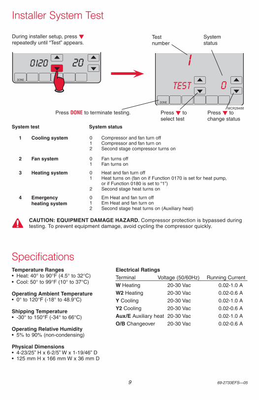
Installer System Test
DONE
200120
DONE
1
0TEST
MCR29488
During installer setup, press t repeatedly until “Test” appears.
Test number
System status
Press t to select test
Press t to change status
Press DONE to terminate testing.
1 Cooling system 0 Compressor and fan turn off1 Compressor and fan turn on2 Second stage compressor turns on
2 Fan system 0 Fan turns off1 Fan turns on
3 Heating system 0 Heat and fan turn off1 Heat turns on (fan on if Function 0170 is set for heat pump,
or if Function 0180 is set to “1”)2 Second stage heat turns on
4 Emergency heating system
0 Em Heat and fan turn off1 Em Heat and fan turn on2 Second stage heat turns on (Auxiliary heat)
System test System status
CAUTION: EQUIPMENT DAMAGE HAZARD. Compressor protection is bypassed during testing. To prevent equipment damage, avoid cycling the compressor quickly.
Temperature Ranges• Heat: 40° to 90°F (4.5° to 32°C)• Cool: 50° to 99°F (10° to 37°C)
Operating Ambient Temperature• 0° to 120°F (-18° to 48.9°C)
Shipping Temperature• -30° to 150°F (-34° to 66°C)
Operating Relative Humidity• 5% to 90% (non-condensing)
Physical Dimensions• 4-23/25” H x 6-2/5” W x 1-19/46” D• 125 mm H x 166 mm W x 36 mm D
Electrical RatingsTerminal Voltage (50/60Hz) Running Current
W Heating 20-30 Vac 0.02-1.0 A
W2 Heating 20-30 Vac 0.02-0.6 A
Y Cooling 20-30 Vac 0.02-1.0 A
Y2 Cooling 20-30 Vac 0.02-0.6 A
Aux/E Auxiliary heat 20-30 Vac 0.02-1.0 A
O/B Changeover 20-30 Vac 0.02-0.6 A
Specifications

Automation and Control Systems
Honeywell International Inc.
1985 Douglas Drive North
Golden Valley, MN 55422
Honeywell Ltd
705 Montrichard Avenue
Saint-Jean-sur-Richelieu, Québec
J2X 5K8
http://customer.honeywell.com
® U.S. Registered Trademark.Apple, iPhone, iPad, iPod touch and iTunes are trademarks of Apple Inc. All other trademarks are the property of their respective owners.© 2014 Honeywell International Inc.69-2733EFS—05 M.S. Rev. 02-14Printed in U.S.A.
VisionPRO® Modèle Wi-Fi TH8320WFThermostat programmable à écran tactile
Configuration du système
Vous faut-il de l’aide ?Pour obtenir de l’assistance concernant ce produit, visitez http://yourhome.honeywell.com
ou appelez gratuitement l’assistance client d’Honeywell au 1-855-733-5465
Ce thermostat fonctionne sur des systèmes 24 V. Il ne fonctionnera PAS sur les systèmes 120/240 V.
Ce thermostat contient une pile au lithium pouvant contenir du perchlorate. Perchlorate — peut exiger une manipulation particulière.Consultez le site www.dtsc.ca.gov/hazardouswaste/perchlorate
AVIS RELATIF AU MERCURE : Ne jetez pas l’ancien thermostat dans la poubelle s’il contient du mercure dans un tube scellé. Contactez la Thermostat Recycling Corporation à l’adresse www.thermostat-recycle.org ou appelez au 1-800-238-8192 pour savoir comment et où mettre au rebut votre thermostat usagé.
AVIS : Pour éviter d’endommager le compresseur, ne faites pas fonctionner le climatiseur si la température extérieure est inférieure à 10 °C (50 °F).
69-2733EFS—05 2
MCR29481
+
+ +
MCR29480
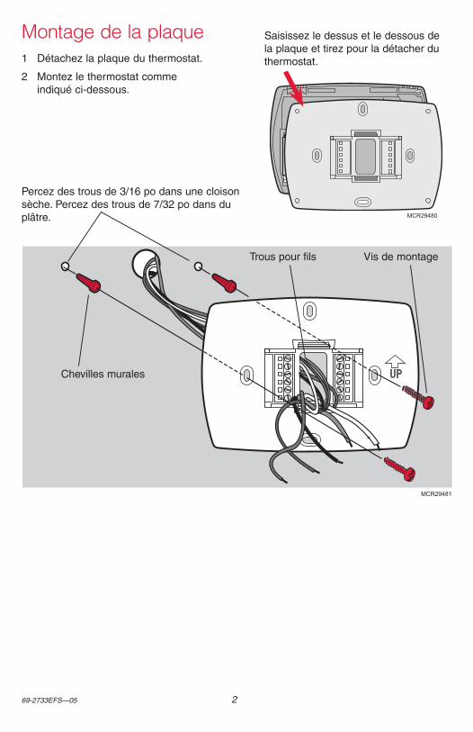
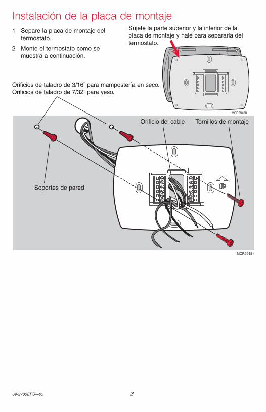
Montage de la plaque1 Détachez la plaque du thermostat.
2 Montez le thermostat comme indiqué ci-dessous.
Saisissez le dessus et le dessous de la plaque et tirez pour la détacher du thermostat.
Percez des trous de 3/16 po dans une cloison sèche. Percez des trous de 7/32 po dans du plâtre.
Chevilles murales
Trous pour fils Vis de montage
3 69-2733EFS—05
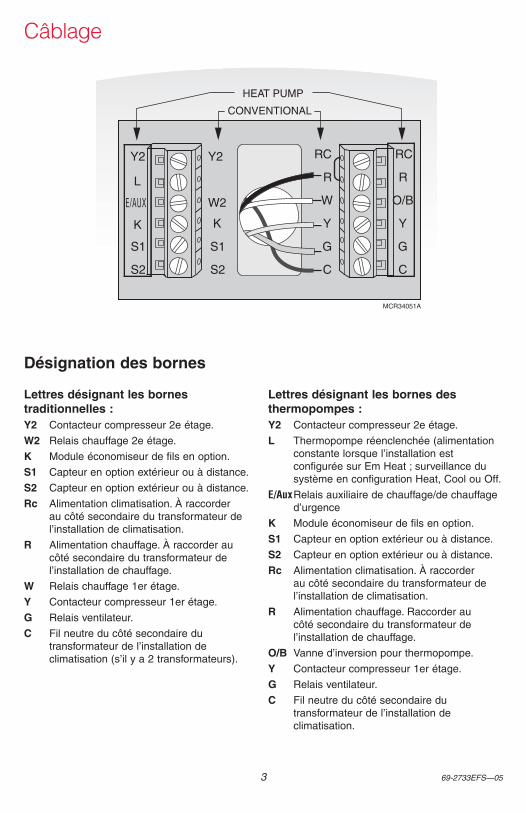
Câblage
Y2
W2
K
S1
S2
RC
R
W
Y
G
C
RC
R
O/B
Y
G
C
HEAT PUMP
CONVENTIONAL
Y2
L
E/AUX
K
S1
S2
MCR34051A
Désignation des bornes
Lettres désignant les bornes traditionnelles :Y2 Contacteur compresseur 2e étage.
W2 Relais chauffage 2e étage.
K Module économiseur de fils en option.
S1 Capteur en option extérieur ou à distance.
S2 Capteur en option extérieur ou à distance.
Rc Alimentation climatisation. À raccorder au côté secondaire du transformateur de l’installation de climatisation.
R Alimentation chauffage. À raccorder au côté secondaire du transformateur de l’installation de chauffage.
W Relais chauffage 1er étage.
Y Contacteur compresseur 1er étage.
G Relais ventilateur.
C Fil neutre du côté secondaire du transformateur de l’installation de climatisation (s’il y a 2 transformateurs).
Lettres désignant les bornes des thermopompes :Y2 Contacteur compresseur 2e étage.
L Thermopompe réenclenchée (alimentation constante lorsque l’installation est configurée sur Em Heat ; surveillance du système en configuration Heat, Cool ou Off.
E/Aux Relais auxiliaire de chauffage/de chauffage d’urgence
K Module économiseur de fils en option.
S1 Capteur en option extérieur ou à distance.
S2 Capteur en option extérieur ou à distance.
Rc Alimentation climatisation. À raccorder au côté secondaire du transformateur de l’installation de climatisation.
R Alimentation chauffage. Raccorder au côté secondaire du transformateur de l’installation de chauffage.
O/B Vanne d’inversion pour thermopompe.
Y Contacteur compresseur 1er étage.
G Relais ventilateur.
C Fil neutre du côté secondaire du transformateur de l’installation de climatisation.
69-2733EFS—05 4
DONE
TUE
15
62012
DONE
TUE
PM1:00
MCR29485
MCR29484
Retirez l’onglet.
Alignez les broches qui se trouvent au dos du thermostat avec les fentes de la plaque, puis poussez avec précaution jusqu’à ce que le thermostat s’emboîte en place.
Retirez l’onglet et montez le thermostat
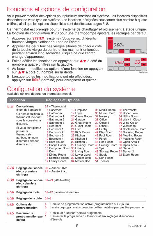
Appuyez st pour régler le mois
Appuyez st pour régler la date
Appuyez st pour régler le mois
Appuyez st pour régler l’année
Appuyez DONE pour sauvegarder les modifications. Appuyez DONE pour sauvegarder et quitter.
Réglez la date et l’heure
Remarque : Une fois enregistré à Total Connect Comfort, le thermostat règle automatiquement l’heure sur le thermostat et il se règle aussi pour passer automatiquement à l’heure d’été/hiver.
5 69-2733EFS—05
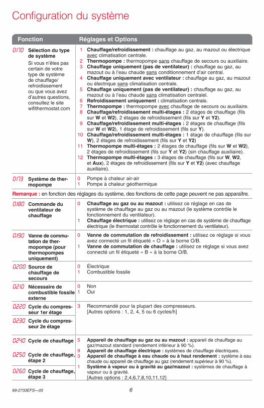
Vous pouvez modifier des options pour plusieurs fonctions du système. Les fonctions disponibles dépendent de votre type de système. Les fonctions, désignées sous forme d’un nombre à quatre chiffres, ainsi que les options disponibles sont décrites aux pages 5–8.
Ce thermostat est préréglé pour un système de chauffage/refroidissement à étage unique. La fonction de configuration 0170 pour une thermopompe ajustera les réglages par défaut.
1 Appuyez sur SYSTEM (système). Vous verrez différents boutons vierges s’afficher au bas de l’écran.
2 Appuyer les deux touches vierges situées de chaque côté de la touche vierge du centre et les maintenir enfoncées pendant environ cinq secondes jusqu’à ce que l’écran change d’apparence.
3 Faites défiler les fonctions en appuyant sur st à côté du nombre à quatre chiffres sur la gauche.
4 Au besoin, modifiez les options d’une fonction en appuyant sur st à côté du nombre sur la droite.
5 Lorsque toutes les modifications ont été effectuées, appuyez sur DONE (terminé) pour enregistrer et quitter.
Fonctions et options de configuration
Configuration du systèmeAvailable options depend on thermostat model.
Fonction Réglages et Options
0112 Device Name (Nom de l’appareil)Ce nom identifiera le thermostat lorsque vous le consultez à distance.Si vous enregistrez plusieurs thermostats, attribuez un nom différent à chacun d’entre eux.
52 = Thermostat 1 Basement 18 Fireplace 35 Media Room 52 Thermostat 2 Bathroom 19 Foyer 36 Music Room 53 Upper Level 3 Bathroom 1 20 Game Room 37 Nursery 54 Utility Room 4 Bathroom 2 21 Garage 38 Office 55 Walk In Closet 5 Bathroom 3 22 Great Room 39 Office 1 56 Wine Cellar 6 Bedroom 23 Guest Room 40 Office 2 57 Workshop 7 Bedroom 1 24 Gym 41 Pantry 64 Conference Room 8 Bedroom 2 25 Kid's Room 42 Play Room 65 Dressing Room 9 Bedroom 3 26 Kitchen 43 Pool Room 66 Meeting Room10 Bedroom 4 27 Kitchen 1 44 Porch 67 Machine Room11 Boat House 28 Kitchen 2 45 Rec Room 68 Open Area 112 Bonus Room 29 Laundry Room 46 Sewing Room 69 Open Area 213 Computer Room 30 Library 47 Spa 70 Server 114 Den 31 Living Room 48 Storage Room 71 Server 215 Dining Room 32 Lower Level 49 Studio 72 Stock Room16 Exercise Room 33 Master Bath 50 Sun Room17 Family Room 34 Master Bed 51 Theater
0120 Réglage de l’année (deux premiers chiffres)
20 = Année 20xx 21 = Année 21xx
0130 Réglage de l’année (deux derniers chiffres)
01–99 (2001–2099)
0140 Réglage du mois 01–12 (janvier–décembre)
0150 Réglage de la date 01–31
0160 Options de programmation
4 Horaire de programmation activé (programmable sur 7 jours).0 Horaire de programmation désactivé. Le thermostat ne peut pas être programmé.
0165 Restaurer la programmation par défaut
0 Continuer à utiliser l’horaire programmé.1 Restaurer le programme du thermostat aux réglages d’économie
d’énergie
DONE CANCEL
TUE
aM6:00
SYSTEM
HEAT
DONE
0120 20
MCR31563
69-2733EFS—05 6
Configuration du système
Fonction Réglages et Options
0170 Sélection du type de systèmeSi vous n’êtes pas certain de votre type de système de chauffage/refroidissement ou que vous avez d’autres questions, consultez le site wifithermostat.com
1 Chauffage/refroidissement : chauffage au gaz, au mazout ou électrique avec climatisation centrale.
2 Thermopompe : thermopompe sans chauffage de secours ou auxiliaire.3 Chauffage uniquement (pas de ventilateur) : chauffage au gaz, au
mazout ou à l’eau chaude sans conditionnement d’air central.4 Chauffage uniquement avec ventilateur : chauffage au gaz, au mazout
ou électrique sans climatisation centrale.5 Chauffage uniquement (pas de ventilateur) : chauffage au gaz, au
mazout ou à l’eau chaude sans climatisation centralel.6 Refroidissement uniquement : climatisation centrale.7 Thermopompe : thermopompe avec chauffage de secours ou auxiliaire.8 Chauffage/refroidissement multi-étages : 2 étages de chauffage (fils
sur W et W2), 2 étages de refroidissement (fils sur Y et Y2).9 Chauffage/refroidissement multi-étages : 2 étages de chauffage (fils
sur W et W2), 1 étage de refroidissement (fils sur Y).10 Chauffage/refroidissement multi-étages : 1 étage de chauffage (fils sur
W), 2 étages de refroidissement (fils sur Y et Y2)11 Thermopompe multi-étages : 2 étages de chauffage (fils sur W et W2),
2 étages de refroidissement (fils sur Y et Y2) (sin chauffage auxiliaire).12 Thermopompe multi-étages : 3 étages de chauffage (fils sur W, W2,
et Aux), 2 étages de refroidissement (fils sur Y et Y2) (avec chauffage auxiliaire).
0173 Système de ther-mopompe
0 Pompe à chaleur air-air1 Pompe à chaleur géothermique
Remarque : en fonction des réglages du système, des fonctions de cette page peuvent ne pas apparaître.
0180 Commande du ventilateur de chauffage
0 Chauffage au gaz ou au mazout : utilisez ce réglage en cas de système de chauffage au gaz ou au mazout (le système contrôle le fonctionnement du ventilateur).
1 Chauffage électrique : utilisez ce réglage en cas de système de chauffage électrique (le thermostat contrôle le fonctionnement du ventilateur).
0190 Vanne de commu-tation de ther-mopompe (pour thermopompes uniquement)
0 Vanne de commutation de refroidissement : utilisez ce réglage si vous avez connecté un fil étiqueté « O » à la borne O/B.
1 Vanne de commutation de chauffage : utilisez ce réglage si vous avez connecté un fil étiqueté « B » à la borne O/B.
0200 Source de chauffage de secours
0 Électrique1 Combustible fossile
0210 Nécessaire de combustible fossile externe
0 Non1 Oui
0220 Cycle du compres-seur 1er étage
3 Recommandé pour la plupart des compresseurs. [Autres options : 1, 2, 4, 5 ou 6 cycles/h]
0230 Cycle du compres-seur 2e étage
0240 Cycle de chauffage 5 Appareil de chauffage au gaz ou au mazout : appareil de chauffage au gaz/mazout standard (rendement inférieur à 90 %).
9 Appareil de chauffage électrique : systèmes de chauffage électriques.3 Appareil de chauffage à eau chaude ou à haut rendement : système à eau
chaude ou appareil de chauffage au gaz (rendement supérieur à 90 %).1 Système à vapeur ou à gravité au gaz/mazout : systèmes de chauffage à
vapeur ou à gravité. [Autres options : 2,4,6,7,8,10,11,12]
0250 Cycle de chauffage, étape 2
0260 Cycle de chauffage, étape 3
7 69-2733EFS—05
Configuration du système
Fonction Réglages et Options
0280 Rétroéclairage 0 Rétroéclairage éteint, puis allumé pendant environ 8 secondes après pression d’une touche.
1 Rétroéclairage toujours allumé à basse intensité, luminosité maximum après pression d’une touche.
0300 Commutation manuelle/automa-tique
0 Commutation manuelle (Chauffage/Refroidissement/Arrêt).1 Commutation automatique (Chauffage/Refroidissement/Auto/Arrêt). Active
automatiquement le chauffage ou le refroidissement en fonction de la température de la pièce. Remarque : le système maintient une différence minimale de 3 °F entre les réglages de chaleur et de refroidissement.
0310 Zone morte de commutation au-tomatique
3 Température chauffage/climatisation avec écart de 3 °F (1,5 °C) [Autres options : 2-9 (2 °F à 9 °F/1 °C à 5 °C)]
0320 Unité de tempéra-ture (°F/°C)
0 Fahrenheit1 Celsius
0330 Réglage automa-tique de l’heure d’été
0 Arrêt1 En marche
0340 Capteur de tem-pérature à distance
0 Aucun1 Extérieur pour affichage2 Extérieur pour régulation3 Intérieur à distance
0346 Minuterie de remontée vers la chaudière de la pompe à chaleur à carburant mixte
0 Arrêt0,5 30 minutes1 1 heure1,5 1,5 heures2 2 heures3 3 heures4 4 heures
5 5 heures6 6 heures8 8 heures10 10 heures12 12 heures14 14 heures16 16 heures
0347 Température de chute (régime per-manent)
2 °F (1,0 °C)[Autres options : affiché en °F ou °C]
0349 Température de chute manuelle du chauffage de secours
0 Confort (désactivé)1 Économie
0350 Verrouillage du compresseur de thermopompe
0 Désactivé [Autres options : affiché en °F ou °C]
0360 Verrouillage aux. de thermopompe
0 Aucun [Autres options : affiché en °F ou °C]
0500 Rappel de remplacement du filtreLe rappel après le nombre de jours de fonctionnement sélectionné, et non pas du nombre de jours réel.
0 Arrêt (pas de rappel)1 Rappel après 10 jours de fonctionnement (environ 1 mois calendrier)2 Rappel après 30 jours de fonctionnement (environ 3 mois calendrier)3 Rappel après 60 jours de fonctionnement (environ 6 mois calendrier)4 Rappel après 90 jours de fonctionnement (environ 9 mois calendrier)5 Rappel après 120 jours de fonctionnement (environ 1 an calendrier)6 Rappel après 180 jours de fonctionnement (environ 18 mois calendrier)7 Rappel après 270 jours de fonctionnement (environ 2 ans calendrier)8 Rappel après 365 jours de fonctionnement (environ 3 ans calendrier)
0502 Filtre de chaudière pour durée de fonc-tionnement
0 Compte de chauffage et de refroidissement1 Compte de refroidissement uniquement
69-2733EFS—05 8
Fonction Réglages et Options
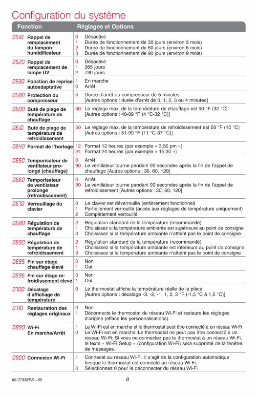
0510 Rappel de remplacement du tampon humidificateur
0 Désactivé1 Durée de fonctionnement de 30 jours (environ 3 mois)2 Durée de fonctionnement de 60 jours (environ 6 mois)3 Durée de fonctionnement de 90 jours (environ 9 mois)
0520 Rappel de remplacement de lampe UV
0 Désactivé1 365 jours2 730 jours
0530 Fonction de reprise autoadaptative
1 En marche0 Arrêt
0580 Protection du compresseur
5 Durée d’arrêt du compresseur de 5 minutes [Autres options : durée d’arrêt de 0, 1, 2, 3 ou 4 minutes]
0600 Buté de plage de température de chauffage
90 Le réglage max. de la température de chauffage est 90 °F (32 °C) [Autres options : 40-89 °F (4 °C-32 °C)]
0610 Buté de plage de température de refroidissement
50 Le réglage max. de la température de refroidissement est 50 °F (10 °C) [Autres options : 51-99 °F (11 °C-37 °C)]
0640 Format de l’horloge 12 Format 12 heures (par exemple « 3:30 pm »)24 Format 24 heures (par exemple « 15:30 »)
0650 Temporisateur de ventilateur pro-longé (chauffage)
0 Arrêt90 Le ventilateur tourne pendant 90 secondes après la fin de l’appel de
chauffage [Autres options : 30, 60, 120]
0660 Temporisateur de ventilateur prolongé (refroidissement)
0 Arrêt90 Le ventilateur tourne pendant 90 secondes après la fin de l’appel de
refroidissement [Autres options : 30, 60, 120]
0670 Verrouillage du clavier
0 Le clavier est déverrouillé (entièrement fonctionnel)1 Partiellement verrouillé (accès aux réglages de température uniquement)2 Complètement verrouillé
0680 Régulation de température de chauffage
2 Régulation standard de la température (recommandé)1 Choisissez si la température ambiante est supérieure au point de consigne3 Choisissez si la température ambiante n’atteint pas le point de consigne
0690 Régulation de température de refroidissement
2 Régulation standard de la température (recommandé)1 Choisissez si la température ambiante est inférieure au point de consigne3 Choisissez si la température ambiante n’atteint pas le point de consigne
0695 Fin sur étage chauffage élevé
0 Non1 Oui
0696 Fin sur étage re-froidissement élevé
0 Non1 Oui
0700 Décalage d’affichage de température
0 Le thermostat affiche la température réelle de la pièce [Autres options : décalage -3, -2, -1, 1, 2, 3 °F (-1,5 °C à 1,5 °C)]
0710 Restauration des réglages originaux
0 Non1 Déconnecte le thermostat du réseau Wi-Fi et restaure les réglages
d’origine (efface les personnalisations).
0890 Wi-Fi En marche/Arrêt
1 Le Wi-Fi est en marche et le thermostat peut être connecté à un réseau Wi-Fi0 Le Wi-Fi est en marche. Le thermostat ne peut pas être connecté à un
réseau Wi-Fi. Si vous ne connectez pas le thermostat à un réseau Wi-Fi, le texte « Wi-Fi Setup » (configuration Wi-Fi) sera supprimé de la fenêtre de messages.
0900 Connexion Wi-Fi 1 Connecté au réseau Wi-Fi. Il s’agit de la configuration automatique lorsque le thermostat est connecté au réseau Wi-Fi.
0 Sélectionnez 0 pour le déconnecter du réseau Wi-Fi.
Configuration du système
9 69-2733EFS—05
Essai du système après installation
DONE
200120
DONE
1
0TEST
MCR29488
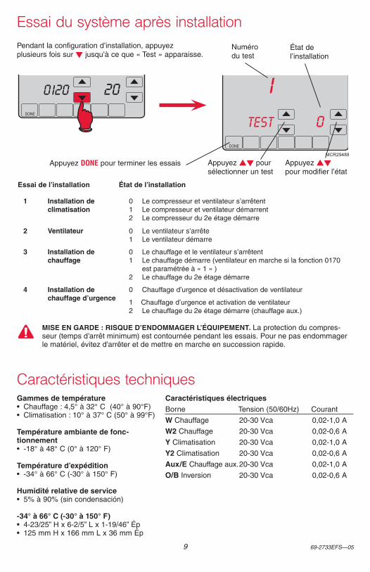
Pendant la configuration d’installation, appuyez plusieurs fois sur t jusqu’à ce que « Test » apparaisse.
Numéro du test
État de l’installation
Appuyez st pour sélectionner un test
Appuyez st pour modifier l’état
Appuyez DONE pour terminer les essais
1 Installation de climatisation
0 Le compresseur et ventilateur s’arrêtent1 Le compresseur et ventilateur démarrent2 Le compresseur du 2e étage démarre
2 Ventilateur 0 Le ventilateur s’arrête1 Le ventilateur démarre
3 Installation de chauffage
0 Le chauffage et le ventilateur s’arrêtent1 Le chauffage démarre (ventilateur en marche si la fonction 0170
est paramétrée à « 1 » ) 2 Le chauffage du 2e étage démarre
4 Installation de chauffage d’urgence
0 Chauffage d’urgence et désactivation de ventilateur
1 Chauffage d’urgence et activation de ventilateur2 Le chauffage du 2e étage démarre (chauffage aux.)
Essai de l’installation État de l’installation
MISE EN GARDE : RISQUE D’ENDOMMAGER L’ÉQUIPEMENT. La protection du compres-seur (temps d’arrêt minimum) est contournée pendant les essais. Pour ne pas endommager le matériel, évitez d'arrêter et de mettre en marche en succession rapide.
Gammes de température• Chauffage : 4,5° à 32° C (40° à 90°F)• Climatisation : 10° à 37° C (50° à 99°F)
Température ambiante de fonc-tionnement• -18° à 48° C (0° à 120° F)
Température d’expédition• -34° à 66° C (-30° à 150° F)
Humidité relative de service• 5% à 90% (sin condensación)
-34° à 66° C (-30° à 150° F)• 4-23/25” H x 6-2/5” L x 1-19/46” Ép• 125 mm H x 166 mm L x 36 mm Ép
Caractéristiques électriquesBorne Tension (50/60Hz) Courant
W Chauffage 20-30 Vca 0,02-1,0 A
W2 Chauffage 20-30 Vca 0,02-0,6 A
Y Climatisation 20-30 Vca 0,02-1,0 A
Y2 Climatisation 20-30 Vca 0,02-0,6 A
Aux/E Chauffage aux. 20-30 Vca 0,02-1,0 A
O/B Inversion 20-30 Vca 0,02-0,6 A
Caractéristiques techniques

® Marque de commerce déposée américaine.Apple, iPhone, iPad, iPod touch et iTunes sont des marques de commerce de Apple Inc. Toutes les autres marques de commerce sont propriété de leurs propriétaires respectifs.© 2014 Honeywell International Inc.69-2733EFS—05 M.S. Rev. 02-14Imprimé aux États-Unis
Systèmes d’automatisation et de régulation
Honeywell International Inc.
1985 Douglas Drive North
Golden Valley, MN 55422
Honeywell Ltd
705 Montrichard Avenue
Saint-Jean-sur-Richelieu, Québec
J2X 5K8
http://customer.honeywell.com
VisionPRO® Wi-Fi Modelo TH8320WFTermostato con pantalla táctil programable
Configuración del sistema
¿Necesita ayuda?Para recibir asistencia con este producto visite http://yourhome.honeywell.com o llame gratis al Servicio de Atención al Cliente Honeywell al 1-855-733-5465
Este termostato funciona con sistemas de 24 voltios. NO funciona con sistemas de 120/240 voltios.
Este termostato tiene una batería de litio que puede contener material con perclorato. Material con perclorato: es posible que deba aplicarse un tratamiento especial. Visite www.dtsc.ca.gov/hazardouswaste/perchlorate
AVISO SOBRE MERCURIO: No coloque el termostato existente en la basura si este contiene mercurio en un tubo sellado. Comuníquese con Thermostat Recycling. Corporation en www.thermostat-recycle.org o al 1-800-238-8192 para obtener información sobre cómo y dónde desechar el termostato de manera adecuada y segura.
AVISO: Para evitar posibles daños al compresor, no utilice el aire acondicionado si la temperatura externa es inferior a 50 °F (10 °C).
69-2733EFS—05 2
MCR29481
+
+ +
MCR29480
Instalación de la placa de montaje1 Separe la placa de montaje del
termostato.
2 Monte el termostato como se muestra a continuación.
Sujete la parte superior y la inferior de la placa de montaje y hale para separarla del termostato.
Orificios de taladro de 3/16” para mampostería en seco. Orificios de taladro de 7/32” para yeso.
Soportes de pared
Orificio del cable Tornillos de montaje

3 69-2733EFS—05
Cableado
Y2
W2
K
S1
S2
RC
R
W
Y
G
C
RC
R
O/B
Y
G
C
HEAT PUMP
CONVENTIONAL
Y2
L
E/AUX
K
S1
S2
MCR34051A
Designaciones de terminales
Letras convencionales:Y2 Contactor del compresor de 2ª etapa.
W2 Retransmisor de calefacción de 2ª etapa.
K Módulo de cableado opcional.
S1 Sensor opcional para exteriores o remoto.
S2 Sensor opcional para exteriores o remoto.
Rc Alimentación de energía de refrigeración. Conecte al lado secundario del transformador del sistema de refrigeración.
R Alimentación de energía de calefacción. Conecte al lado secundario del transformador del sistema de calefacción.
W Retransmisor de calefacción de 1ª etapa.
Y Contactor del compresor de 1ª etapa.
G Retransmisor del ventilador.
C Cable común del lado secundario del transformador del sistema de refrigeración (si hay 2 transformadores).
Letras de la bomba de calefacción:Y2 Contactor del compresor de 2ª etapa.
L Reajuste de la bomba de calefacción (recibe alimentación de energía cuando el sistema se ajusta en Em Heat; monitor del sistema cuando se ajusta en Heat, Cool u Off).
E/Aux Retransmisor auxiliar de calefacción. Retransmisor de calefacción de emergencia.
K Módulo de cableado opcional.
S1 Sensor opcional para exteriores o remoto.
S2 Sensor opcional para exteriores o remoto.
Rc Alimentación de energía de refrigeración. Conecte al lado secundario del transformador del sistema de refrigeración.
R Alimentación de energía de calefacción. Conecte al lado secundario del transformador del sistema de calefacción.
O/B Válvula de cambio para bombas de calefacción.
Y Contactor del compresor de 1ª etapa.
G Retransmisor del ventilador.
C Cable común del lado secundario del transformador del sistema de refrigeración.
69-2733EFS—05 4
DONE
TUE
15
62012
DONE
TUE
PM1:00
MCR29485
MCR29484
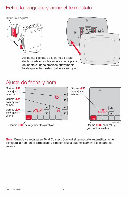
Retire la lengüeta.
Alinee las espigas de la parte de atrás del termostato con las ranuras de la placa de montaje, luego presione suavemente hasta que el termostato calce en su lugar.
Retire la lengüeta y arme el termostato
Oprima st para ajustar la hora
Oprima st para ajustar la fecha
Oprima st para ajustar el mes
Oprima st para ajustar el año
Oprima DONE para guardar los cambios. Oprima DONE para salir yguardar los ajustes.
Ajuste de fecha y hora
Nota: Cuando se registra en Total Connect Comfort el termostato automáticamente configura la hora en el termostato y también ajusta automáticamente el horario de verano.
5 69-2733EFS—05
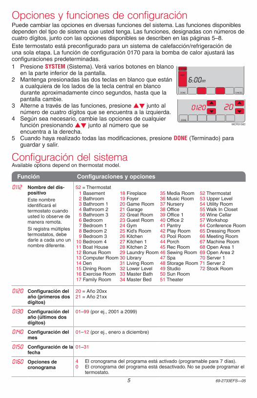
Opciones y funciones de configuraciónPuede cambiar las opciones en diversas funciones del sistema. Las funciones disponibles dependen del tipo de sistema que usted tenga. Las funciones, designadas con números de cuatro dígitos, junto con las opciones disponibles se describen en las páginas 5–8.Este termostato está preconfigurado para un sistema de calefacción/refrigeración de una sola etapa. La función de configuración 0170 para la bomba de calor ajustará las configuraciones predeterminadas.1 Presione SYSTEM (Sistema). Verá varios botones en blanco
en la parte inferior de la pantalla.2 Mantenga presionadas las dos teclas en blanco que están
a cualquiera de los lados de la tecla central en blanco durante aproximadamente cinco segundos, hasta que la pantalla cambie.
3 Alterne a través de las funciones, presione st junto al número de cuatro dígitos que se encuentra a la izquierda.
4 Según sea necesario, cambie las opciones de cualquier función presionando st junto al número que se encuentra a la derecha.
5 Cuando haya realizado todas las modificaciones, presione DONE (Terminado) para guardar y salir.
Configuración del sistemaAvailable options depend on thermostat model.
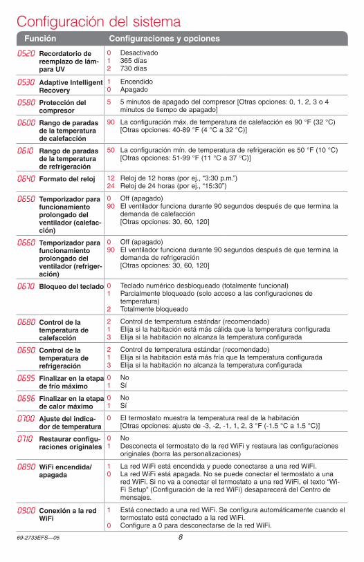
Función Configuraciones y opciones
0112 Nombre del dis-positivoEste nombre identificará el termostato cuando usted lo observe de manera remota.Si registra múltiples termostatos, debe darle a cada uno un nombre diferente.
52 = Thermostat 1 Basement 18 Fireplace 35 Media Room 52 Thermostat 2 Bathroom 19 Foyer 36 Music Room 53 Upper Level 3 Bathroom 1 20 Game Room 37 Nursery 54 Utility Room 4 Bathroom 2 21 Garage 38 Office 55 Walk In Closet 5 Bathroom 3 22 Great Room 39 Office 1 56 Wine Cellar 6 Bedroom 23 Guest Room 40 Office 2 57 Workshop 7 Bedroom 1 24 Gym 41 Pantry 64 Conference Room 8 Bedroom 2 25 Kid's Room 42 Play Room 65 Dressing Room 9 Bedroom 3 26 Kitchen 43 Pool Room 66 Meeting Room10 Bedroom 4 27 Kitchen 1 44 Porch 67 Machine Room11 Boat House 28 Kitchen 2 45 Rec Room 68 Open Area 112 Bonus Room 29 Laundry Room 46 Sewing Room 69 Open Area 213 Computer Room 30 Library 47 Spa 70 Server 114 Den 31 Living Room 48 Storage Room 71 Server 215 Dining Room 32 Lower Level 49 Studio 72 Stock Room16 Exercise Room 33 Master Bath 50 Sun Room17 Family Room 34 Master Bed 51 Theater
0120 Configuración del año (primeros dos dígitos)
20 = Año 20xx 21 = Año 21xx
0130 Configuración del año (últimos dos dígitos)
01–99 (por ej., 2001 a 2099)
0140 Configuración del mes
01–12 (por ej., enero a diciembre)
0150 Configuración de la fecha
01–31
0160 Opciones de cronograma
4 El cronograma del programa está activado (programable para 7 días).0 El cronograma del programa está desactivado. No se puede programar el
termostato.
DONE CANCEL
TUE
aM6:00
SYSTEM
HEAT
DONE
0120 20
MCR31563
69-2733EFS—05 6
Configuración del sistema
Función Configuraciones y opciones
0165 Recuperar configuraciones predeterminadas
0 Continúe utilizando el cronograma programado.1 Restablezca la programación del termostato a la configuración de ahorro
de energía.
0170 Seleccionar el tipo de sistemaSi no está seguro sobre el tipo de sistema de calefacción/refrigeración que tiene o si tiene alguna otra pregunta, visite wifithermostat.com
1 Calor/frío: Calefacción a gas, aceite o eléctrica con aire acondicionado central.
2 Bomba de calor: Bomba de calor sin calor de reserva ni calor auxiliar.3 Calefacción únicamente (sin ventilador): Calefacción a gas, aceite o
agua caliente sin aire acondicionado central.4 Calefacción únicamente con ventilador: Calefacción a gas, aceite o
eléctrica sin aire acondicionado central.5 Calefacción únicamente (sin ventilador): Calefacción a gas, aceite o
agua caliente sin aire acondicionado central.6 Refrigeración únicamente: Aire acondicionado central únicamente.7 Bomba de calor: Bomba de calor con calor de reserva o auxiliar.8 Etapas múltiples de calefacción/refrigeración: 2 etapas de calefacción
(cables en W y W2); 2 etapas de refrigeración (cables en Y e Y2).9 Etapas múltiples de calefacción/refrigeración: 2 etapas de calefacción
(cables en W y W2); 1 etapa de refrigeración (cable en Y).10 Etapas múltiples de calefacción/refrigeración: 1 etapa de calefacción
(cable en W); 2 etapas de refrigeración (cables en Y e Y2).11 Bomba de calor etapas múltiples: 2 etapas de calefacción (cables
en W e W2), 2 etapas de refrigeración (cables en Y e Y2) (sin calor de auxiliar).
12 Bomba de calor etapas múltiples: 3 etapas de calefacción (cables en W, W2, e Aux), 2 etapas de refrigeración (cables en Y e Y2) (con calor de auxiliar).
0173 Sistema de bomba de calor
0 Bomba de calor aire a aire1 Bomba de calor geotérmica
Nota: según las configuraciones del sistema, es posible que las funciones de esta página no aparezcan.
0180 Control del ventila-dor de calefacción
0 Calefacción a gas o aceite: Utilice esta configuración si tiene un sistema de calefacción a gas o aceite (el sistema controla el funcionamiento del ventilador).
1 Calor eléctrico: Utilice esta configuración si tiene un sistema de calefacción eléctrico (el termostato controla el funcionamiento del ventilador).
0190 Válvula de cambio para bombas de calor (bombas de calor únicamente)
0 Válvula de cambio de refrigeración: Utilice esta configuración si conectó un cable con la etiqueta “O” al terminal O/B.
1 Válvula de cambio de calefacción: Utilice esta configuración si conectó un cable con la etiqueta “B” al terminal O/B.
0200 Fuente de calor de reserva
0 Eléctrica1 Combustible fósil
0210 Kit de combustible fósil externo
0 No1 Sí
0220 Índice del ciclo del compresor en la 1
a
etapa
3 Se recomienda para la mayoría de los compresores. [Otras opciones: 1, 2, 4, 5 ó 6 CPH]
0230 Índice del ciclo del compresor en la 2
a
etapa
0240 Frecuencia del ciclo de calefacción
5 Equipo de calefacción a gas o aceite: Equipo de calefacción estándar a gas o aceite (menos del 90% de eficacia).
9 Equipo de calefacción eléctrica: Sistemas de calefacción eléctrica.3 Equipo de calefacción con agua caliente o de gran eficiencia: Equipo
de calefacción con agua caliente o a gas (más del 90% de eficacia).1 Sistema de vapor o gravedad a gas/aceite: Sistemas de calefacción por
vapor o gravedad. [Otras opciones: 2,4,6,7,8,10,11,12]
0250 Frecuencia del ci-clo de calefacción, etapa 2
0260 Frecuencia del ci-clo de calefacción, etapa 3
7 69-2733EFS—05
Función Configuraciones y opciones
0280 Iluminación de fondo
0 La luz de fondo se apaga y, luego, se enciende durante, aproximadamente, 8 segundos después de presionar la tecla.
1 La luz de fondo siempre se mantiene encendida a baja intensidad y brillo total después de presionar la tecla.
0300 Cambio manual/automático
0 Cambio manual (Heat/Cool/Off [Calor/Frío/Apagado]).1 Cambio automático (Heat/Cool/Off [Calor/Frío/Apagado]). Activa,
automáticamente, la calefacción o la refrigeración conforme a la temperatura ambiente. Nota: el sistema mantiene una diferencia mínima de 3 °F entre las configuraciones de calefacción y refrigeración.
0310 Conversión de banda muerta automática
3 Temperatura de calefacción/refrigeración con una diferencia de 3 °F (1.5 °C) [Otras opciones: de 2 a 9 [de 2 °F a 9 °F/de 1 °C a 5 °C)]
0320 Formato de la tem-peratura (°F/°C)
0 Fahrenheit1 Centígrados
0330 Ajuste de horario de verano automático
0 Apagado1 Encendido
0340 Sensor remoto de temperatura
0 Ninguno1 Exterior para visualización
2 Exterior para control3 Interior remoto
0346 Cambio de la bomba de calor de combustible dual al temporizador del sistema de calefac-ción
0 Apagado0.5 30 minutos1 1 hora1.5 1.5 horas2 2 horas3 3 horas4 4 horas
5 5 horas6 6 horas8 8 horas 10 10 horas12 12 horas14 14 horas16 16 horas
0347 Temperatura de descenso (estado constante)
2 °F (1.0 °C) [Otras opciones: se muestran en °F o °C]
0349 Temperatura de de-scenso manual del calor de reserva
0 Confort (Off [apagado])1 Ahorro
0350 Bloqueo del com-presor de la bomba de calor
0 Off (apagado) [Otras opciones: se muestran en °F o °C]
0360 Bloqueo de la bomba de calor auxiliar
0 Ninguno [Otras opciones: se muestran en °F o °C]
0500 Recordatorio de cambio del filtroEl recordatorio aparece después de la cantidad de días seleccionados de tiempo de funcionamiento, no del tiempo real.
0 Apagado (sin recordatorio)Recordatorio después de:1 10 días de tiempo de funcionamiento (aprox., 1 mes calendario)2 30 días de tiempo de funcionamiento (aprox., 3 meses calendario)3 60 días de tiempo de funcionamiento (aprox., 6 meses calendario)4 90 días de tiempo de funcionamiento (aprox., 9 meses calendario)5 120 días de tiempo de funcionamiento (aprox., 1 año calendario)6 180 días de tiempo de funcionamiento (aprox., 18 meses calendario)7 270 días de tiempo de funcionamiento (aprox., 2 años calendario)8 365 días de tiempo de funcionamiento (aprox., 3 años calendario)
0502 Tiempo de fun-cionamiento del filtro del sistema de calefacción
0 Cuenta el tiempo de funcionamiento de calor y frío1 Cuenta el tiempo de funcionamiento de frío únicamente
0510 Recordatorio de reemplazo de la almohadilla del humidificador
0 Desactivado1 Tiempo de funcionamiento de 30 días (aproximadamente 3 meses)2 Tiempo de funcionamiento de 60 días (aproximadamente 6 meses)3 Tiempo de funcionamiento de 90 días (aproximadamente 9 meses)
Configuración del sistema
69-2733EFS—05 8
Función Configuraciones y opciones
0520 Recordatorio de reemplazo de lám-para UV
0 Desactivado1 365 días2 730 días
0530 Adaptive Intelligent Recovery
1 Encendido0 Apagado
0580 Protección del compresor
5 5 minutos de apagado del compresor [Otras opciones: 0, 1, 2, 3 o 4 minutos de tiempo de apagado]
0600 Rango de paradas de la temperatura de calefacción
90 La configuración máx. de temperatura de calefacción es 90 °F (32 °C) [Otras opciones: 40-89 °F (4 °C a 32 °C)]
0610 Rango de paradas de la temperatura de refrigeración
50 La configuración mín. de temperatura de refrigeración es 50 °F (10 °C) [Otras opciones: 51-99 °F (11 °C a 37 °C)]
0640 Formato del reloj 12 Reloj de 12 horas (por ej., “3:30 p.m.”)24 Reloj de 24 horas (por ej., “15:30”)
0650 Temporizador para funcionamiento prolongado del ventilador (calefac-ción)
0 Off (apagado)90 El ventilador funciona durante 90 segundos después de que termina la
demanda de calefacción [Otras opciones: 30, 60, 120]
0660 Temporizador para funcionamiento prolongado del ventilador (refriger-ación)
0 Off (apagado)90 El ventilador funciona durante 90 segundos después de que termina la
demanda de refrigeración [Otras opciones: 30, 60, 120]
0670 Bloqueo del teclado 0 Teclado numérico desbloqueado (totalmente funcional)1 Parcialmente bloqueado (solo acceso a las configuraciones de
temperatura)2 Totalmente bloqueado
0680 Control de la temperatura de calefacción
2 Control de temperatura estándar (recomendado)1 Elija si la habitación está más cálida que la temperatura configurada3 Elija si la habitación no alcanza la temperatura configurada
0690 Control de la temperatura de refrigeración
2 Control de temperatura estándar (recomendado)1 Elija si la habitación está más fría que la temperatura configurada3 Elija si la habitación no alcanza la temperatura configurada
0695 Finalizar en la etapa de frío máximo
0 No1 Sí
0696 Finalizar en la etapa de calor máximo
0 No1 Sí
0700 Ajuste del indica-dor de temperatura
0 El termostato muestra la temperatura real de la habitación [Otras opciones: ajuste de -3, -2, -1, 1, 2, 3 °F (-1.5 °C a 1.5 °C)]
0710 Restaurar configu-raciones originales
0 No1 Desconecta el termostato de la red WiFi y restaura las configuraciones
originales (borra las personalizaciones)
0890 WiFi encendida/apagada
1 La red WiFi está encendida y puede conectarse a una red WiFi.0 La red WiFi está apagada. No se puede conectar el termostato a una
red WiFi. Si no va a conectar el termostato a una red WiFi, el texto “Wi-Fi Setup” (Configuración de la red WiFi) desaparecerá del Centro de mensajes.
0900 Conexión a la red WiFi
1 Está conectado a una red WiFi. Se configura automáticamente cuando el termostato está conectado a la red WiFi.
0 Configure a 0 para desconectarse de la red WiFi.
Configuración del sistema
9 69-2733EFS—05
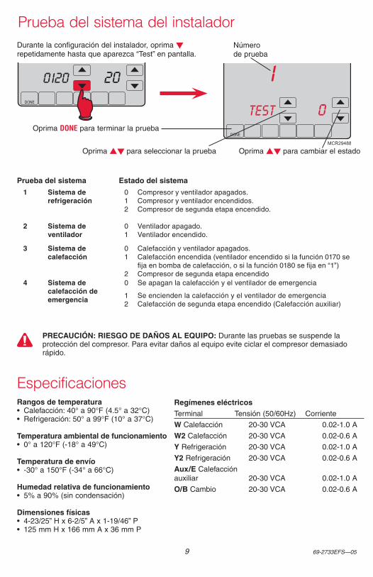
Prueba del sistema del instalador
DONE
200120
DONE
1
0TEST
MCR29488
Durante la configuración del instalador, oprima t repetidamente hasta que aparezca “Test” en pantalla.
Número de prueba
Oprima st para seleccionar la prueba
Oprima DONE para terminar la prueba
1 Sistema de refrigeración
0 Compresor y ventilador apagados.1 Compresor y ventilador encendidos.2 Compresor de segunda etapa encendido.
2 Sistema de ventilador
0 Ventilador apagado.1 Ventilador encendido.
3 Sistema de calefacción
0 Calefacción y ventilador apagados.1 Calefacción encendida (ventilador encendido si la función 0170 se
fija en bomba de calefacción, o si la función 0180 se fija en “1”)2 Compresor de segunda etapa encendido
4 Sistema de calefacción de emergencia
0 Se apagan la calefacción y el ventilador de emergencia
1 Se encienden la calefacción y el ventilador de emergencia2 Calefacción de segunda etapa encendido (Calefacción auxiliar)
Prueba del sistema Estado del sistema
Oprima st para cambiar el estado
PRECAUCIÓN: RIESGO DE DAÑOS AL EQUIPO: Durante las pruebas se suspende la protección del compresor. Para evitar daños al equipo evite ciclar el compresor demasiado rápido.
Rangos de temperatura• Calefacción: 40° a 90°F (4.5° a 32°C)• Refrigeración: 50° a 99°F (10° a 37°C)
Temperatura ambiental de funcionamiento• 0° a 120°F (-18° a 49°C)
Temperatura de envío• -30° a 150°F (-34° a 66°C)
Humedad relativa de funcionamiento• 5% a 90% (sin condensación)
Dimensiones físicas• 4-23/25” H x 6-2/5” A x 1-19/46” P• 125 mm H x 166 mm A x 36 mm P
Regímenes eléctricosTerminal Tensión (50/60Hz) Corriente
W Calefacción 20-30 VCA 0.02-1.0 A
W2 Calefacción 20-30 VCA 0.02-0.6 A
Y Refrigeración 20-30 VCA 0.02-1.0 A
Y2 Refrigeración 20-30 VCA 0.02-0.6 A
Aux/E Calefacción auxiliar 20-30 VCA 0.02-1.0 A
O/B Cambio 20-30 VCA 0.02-0.6 A
Especificaciones

69-2733EFS—05 10

11 69-2733EFS—05

® Marca Registrada en los E.U.A.Apple, iPhone, iPad, iPod touch y iTunes son marcas comerciales de Apple Inc. Todas las demás marcas comerciales son propiedad de sus respectivos dueños.© 2014 Honeywell International Inc.69-2733EFS—05 M.S. Rev. 02-14Impreso en EE. UU.
Automatización y control desenlace
Honeywell International Inc.
1985 Douglas Drive North
Golden Valley, MN 55422
Honeywell Ltd
705 Montrichard Avenue
Saint-Jean-sur-Richelieu, Québec
J2X 5K8
http://customer.honeywell.com