Collaborative Robots Market – Global Research Report 2015-2019
Upload
truongnguyetCategory
view
219download
0
Vision Systems for Collaborative Robots
robotiq.com

Vision Systems for Collaborative Robots
Table of Contents
Table of Contents
Introduction
What Can You Do with a Vision System?
Vision System Applications and Alternatives
What Kinds of Vision Systems Are Available?
1D Technologies
2D Technologies
3D Technologies
Choosing the Correct 2D Vision System for Your Application
Image Processing Terms
Challenges of a Vision System for Template Matching
So what Do I Start with then?
Conclusion
About Robotiq
Let’s Keep in Touch
Other Interesting eBooks
Page 2 robotiq.com

Vision Systems for Collaborative Robots
Introduction
Are you thinking about integrating vision into your current system? Are you planning your next
automation? Would you like to add a vision component? Have you just bought a vision system and
need to understand how vision systems work a bit better? If any of the above applies to you, just keep
reading!
You will see that there are a lot of different vision systems out there. Many of them use different
techniques or different technologies and apply these different concepts to many different types of
applications. So, it is important that you acquire some basic knowledge of machine vision to help you
figure out exactly what a simple vision application is. It might also be useful to understand the
differences between this type of application and a more complex one. So, if you are just starting with
vision, or if you think adding vision to your system might solve one of your pet peeves, this eBook will
be a great place to start.
Page 3 robotiq.com

Vision Systems for Collaborative Robots
What Can You Do with a Vision System? Adding a sense of vision to your robot can open up a world of possibilities. Not so long ago, most
robots were blind… Think of everything you actually do with your eyes, and you start seeing the
possibilities: part inspection, check specific features of a part, recognize a part to pick it up, count
items, adjust the robot’s path with feedback from your vision system, color sorting, barcode reading,
bin picking and so on. You can see that there are many applications out there; so the upfront
evaluation of your project is critical to making sure you select the right technology for the job.
There are three different aspects of a vision system that will determine if it’s an easy or a complex
system.
The first one involves capturing the image. This principle is quite simple; you want to enhance the
features you want to see and dampen everything else. Doing this can be quite an art. It all depends on
your application and setup. Working with highly reflective metallic parts, for example, can be quite
challenging. You will need to focus on techniques used in photography to achieve a satisfactory result.
The second aspect concerns the analysis of the images. If the capturing of the image has been done
correctly, you should have a sharp contrast between the background and the object. For example, a
black rectangle part lying on a white backlighted surface. If this is the case, then you will be able to
use simple image analysis tools to recognize the shape of the object. If, on the other hand, you need
to find a target in a 3D space where you have many objects in the camera’s field of view; then your
application will be much more complicated. So, in summary, sharp contrasts and easy to recognize
shapes will end up giving you easy image analysis. If the shape you are looking to recognize varies
from one part to another or if the contrast varies from time to time; then you will benefit from having
more advanced knowledge in vision systems. This will make it easier to put together the right tools
that will give you the best results for your image analysis. You can deduce that capturing & image
analysis are directly related. Sometimes it is worth working harder on the image capturing
functionality, in order to make the image analysis stage easier. If however, there are variations you
can’t handle at the capturing stage, using more advanced image analysis tools might be able to help
you out.
The third aspect of a vision process to consider, and which will also be related to its complexity, is
what you want to do with the vision data. That is, once you have found the part and you have its
coordinates, what do you want to do with this information? Simple vision projects may only establish
a pass/fail status determining if the part has been found or not. There are many tools out there that
will allow you to easily set up this kind of application. However, if you need to send the data to the
robot, so that the robot can pick up the part, this is a totally different story. In this type of application
there are a lot more mathematics to workout. First, you need to calibrate the camera frame, so that
the robot will know where the camera’s focus point is. Then, you need to calibrate the plane of the
object that you want to locate. After this, you need to convert the positions of the objects that were
found in the camera’s coordinate system to the robot’s coordinate system. If you are not used to
Page 4 robotiq.com

Vision Systems for Collaborative Robots
linear algebra or you have not done any in a long time, this is prime territory for developing
headaches. To avoid this you might want to use tools that are already integrated with a robot, like the
Robotiq Wrist Camera. An integrated system will take care of all of this for you pretty easily. Actually,
you won’t even need your linear algebra skills to setup an application with this kind of system.
Vision System Applications and Alternatives But what about other alternatives? If you’re confused about whether or not a vision system is the way
to go to accomplish your project, check out these alternatives and the comments related to them.
Pick & Place:
The key aspect in a pick and place application that is likely to influence your decision between using a
vision system or another option is usually the part presentation. You need to locate the parts in order
to let the robot know where to pick them up. Below are some options that will solve part localization
for pick and place applications. Note that here we are talking about the pick position, but the same
factors apply to the place position. Depending on what you need to do when placing your part, you
may need a vision system to determine the proper place position also. An example of this might be
locating the box in which the part is to be placed.
● Fixtures: Your parts are placed in trays or secured with fixtures. So they are always at a
constant position relative to the robot. This is usually really simple to do and program. You
simply need to teach the positions to the robot. Some robot models come with palletizing
programs that will help you teach positions fast. If you already have this kind of setup, then
using vision is probably overkill. If, however, you don’t have such a system, then consider the
following: designing a fixture can be costly depending on the part you have. Also, fixtures can
get tricky to design if you want to feed a lot of parts to the robot without recharging the jigs.
In this case, you need to be able to place as many parts as possible within the robot’s reach.
Another downside to this is if you have several different parts that have to be picked by the
robot. In this case, you may need several different jigs which would therefore add to the cost,
plus you should consider changeover time when you are estimating the efficiency of the
system.
● Bowl Feeders: These are meant to take bulk items and singularize them such that one part at
a time would be presented to the robot and the robot would always pick this part from the
same position. Once a setup like this is installed and adjusted correctly, it usually works great.
You only have one pick position that you need to program into your robot to pick up the part.
However, this type of equipment can be quite expensive and hard to adjust depending on the
shape of the parts you are picking. Furthermore, with a bowl feeder most of the time you are
stuck with the option of sorting only one kind of part. Switching between different parts will
require you to add another bowl feeding system to your robot cell.
Page 5 robotiq.com
Vision Systems for Collaborative Robots
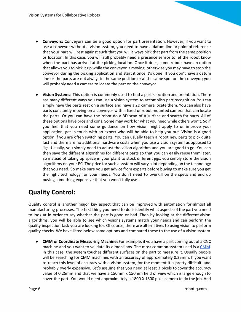
● Conveyors: Conveyors can be a good option for part presentation. However, if you want to use a conveyor without a vision system, you need to have a datum line or point of reference that your part will rest against such that you will always pick that part from the same position or location. In this case, you will still probably need a presence sensor to let the robot know when the part has arrived at the picking location. Once it does, some robots have an option that allows you to pick it up while the conveyor is moving, otherwise you may have to stop the conveyor during the picking application and start it once it’s done. If you don’t have a datum line or the parts are not always in the same position or at the same spot on the conveyor; you will probably need a camera to locate the part on the conveyor.
● Vision Systems: This option is commonly used to find a part’s location and orientation. There
are many different ways you can use a vision system to accomplish part recognition. You can simply have the parts rest on a surface and have a 2D camera locate them. You can also have parts constantly moving on a conveyor with a fixed or robot mounted camera that can locate the parts. Or you can have the robot do a 3D scan of a surface and search for parts. All of these options have pros and cons. Some may work for what you need while others won’t. So if you feel that you need some guidance on how vision might apply to or improve your application, get in touch with an expert who will be able to help you out. Vision is a good option if you are often switching parts. You can usually teach a robot new parts to pick quite fast and there are no additional hardware costs when you use a vision system as opposed to jigs. Usually, you simply need to adjust the vision algorithm and you are good to go. You can then save the different algorithms for different parts so that you can easily reuse them later. So instead of taking up space in your plant to stock different jigs, you simply store the vision algorithms on your PC. The price for such a system will vary a lot depending on the technology that you need. So make sure you get advice from experts before buying to make sure you get the right technology for your needs. You don’t need to overkill on the specs and end up buying something expensive that you won't fully use!
Quality Control: Quality control is another major key aspect that can be improved with automation for almost all manufacturing processes. The first thing you need to do is identify what aspects of the part you need to look at in order to say whether the part is good or bad. Then by looking at the different vision algorithms, you will be able to see which visions systems match your needs and can perform the quality inspection task you are looking for. Of course, there are alternatives to using vision to perform quality checks. We have listed below some options and compared these to the use of a vision system.
● CMM or Coordinate Measuring Machine: For example, if you have a part coming out of a CNC machine and you want to validate its dimensions. The most common system used is a CMM. In this case, the system touches different surfaces on the part to measure it. Usually people will be searching for CMM machines with an accuracy of approximately 0.25mm. If you want to reach this level of accuracy with a vision system, for the moment it is pretty difficult and probably overly expensive. Let’s assume that you need at least 3 pixels to cover the accuracy value of 0.25mm and that we have a 150mm x 150mm field of view which is large enough to cover the part. You would need approximately a 1800 X 1800 pixel camera to do the job. And
Page 6 robotiq.com

Vision Systems for Collaborative Robots
this does not take into account any lighting challenges that may come with the images of shiny metal objects coming out of a CNC machine.
● Eddy Current: This technique can be used to detect a part’s position and its defects. Due to its
high sensitivity, you will be able to detect small cracks, deformities, pits, etc. However, using eddy currents are limited to conductive materials whereas using a vision system is not.
● Vision: If you are on a production line where products are coming out on a conveyor and you
simply need to check part presence and do some measurement analysis without extreme precision, then vision will be the best option. This is because the camera is able to take a snapshot of the part as it is moving on the conveyor. Thus you could perform live quality checks on the part without having to remove it from the production process and instead of doing batch sample testing. You are actually testing every product coming down that line.
To judge if vision can help your quality inspection processes, here is a list of vision functions often used in quality inspections:
● Pattern Matching: You teach a few good parts and a few bad parts to the camera. The camera will set a pass/fail threshold. Then, when taking an image of a new part, it will indicate if this part matches the threshold you have set. This is often used when you need to check a part for deformities or for the presence of a specific object on the part (e.g. holes in a part or a cap on a bottle).
● Color Matching: Some vision systems can allow you to confirm the color of an object.
● Optical Character Recognition (OCR): This is often used to confirm some printing on the
product, making sure it is visible or written correctly and consistently with what was supposed to be printed.
● Measuring: There are various measuring methods available in vision systems that can be used
to do measurement checks through the use of images. For example, measuring the distance between edges or the distance between holes and so on.
● Filters: You can detect visual defects (pits, holes, cracks, etc.) using various filtering
techniques, like blob analysis. More on this in the Image processing terms section!
● Counting: This is a bit like measuring, but you can count how many objects there are or how many holes are present on apart.
Page 7 robotiq.com

Vision Systems for Collaborative Robots
What Kinds of Vision Systems Are Available? 2D cameras are not the only vision systems that are available out there. Think of a line scanner that
scans a barcode: that’s a 1D sensor.
1D Technologies
A 1D sensor is sufficient if you want to measure the height of a part that moves on a conveyor. You
could use a distance sensor that has a single laser point to measure the distance from the sensor to
the surface. A single laser point is displayed on a surface and most of the time, triangulation is used to
get the distance value. So it is only possible to get data for one axis with this kind of technology.
Image link
Page 8 robotiq.com
Vision Systems for Collaborative Robots
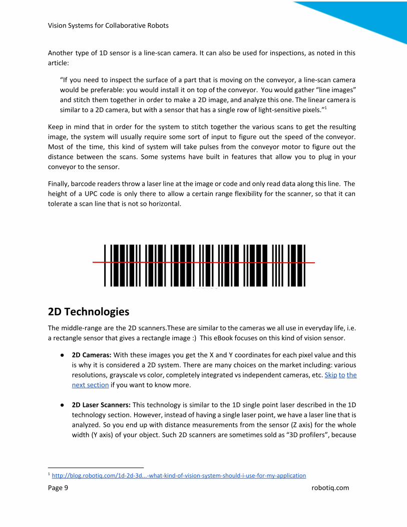
Another type of 1D sensor is a line-scan camera. It can also be used for inspections, as noted in this
article:
“If you need to inspect the surface of a part that is moving on the conveyor, a line-scan camera
would be preferable: you would install it on top of the conveyor. You would gather “line images”
and stitch them together in order to make a 2D image, and analyze this one. The linear camera is
similar to a 2D camera, but with a sensor that has a single row of light-sensitive pixels.” 1
Keep in mind that in order for the system to stitch together the various scans to get the resulting
image, the system will usually require some sort of input to figure out the speed of the conveyor.
Most of the time, this kind of system will take pulses from the conveyor motor to figure out the
distance between the scans. Some systems have built in features that allow you to plug in your
conveyor to the sensor.
Finally, barcode readers throw a laser line at the image or code and only read data along this line. The
height of a UPC code is only there to allow a certain range flexibility for the scanner, so that it can
tolerate a scan line that is not so horizontal.
2D Technologies The middle-range are the 2D scanners.These are similar to the cameras we all use in everyday life, i.e.
a rectangle sensor that gives a rectangle image :) This eBook focuses on this kind of vision sensor.
● 2D Cameras: With these images you get the X and Y coordinates for each pixel value and this
is why it is considered a 2D system. There are many choices on the market including: various
resolutions, grayscale vs color, completely integrated vs independent cameras, etc. Skip to the
next section if you want to know more.
● 2D Laser Scanners: This technology is similar to the 1D single point laser described in the 1D
technology section. However, instead of having a single laser point, we have a laser line that is
analyzed. So you end up with distance measurements from the sensor (Z axis) for the whole
width (Y axis) of your object. Such 2D scanners are sometimes sold as “3D profilers”, because
1 http://blog.robotiq.com/1d-2d-3d...-what-kind-of-vision-system-should-i-use-for-my-application
Page 9 robotiq.com

Vision Systems for Collaborative Robots
they can be combined with the movement of the part on a conveyor to determine to the
other axis (X axis).
image link
The principle is the same as for the line-scan camera we have seen above: hook up the
encoder pulses from the conveyor to the vision system, and stitch the scans together using
this speed information. This can be a bit confusing actually, since you can also find 4D
scanners on the market. These take multiple 3D measurements, so 3D + the time variable =
4D. If you want to know the real number of dimensions, focus on the sensor itself. In this case,
laser distance sensors that measure the distance (first dimension) along a line (second
dimension) = 2D scanner.
3D Technologies Another option is the 3D scanner (we’ll come back to the 2D sensors in a minute). These scanners are
used for reverse engineering, metrology, more exact measurements (e.g. defect depth), etc. 3D
scanners use various techniques like: Shape from Shading, laser triangulation, structured lighting, etc.
You can read more about them here. Depending on the technique, you can either get approximate
data (that can still be sufficient for your needs) in a few seconds or extra precise data that will take
longer to scan & process (it could be minutes).
Page 10
robotiq.com

Vision Systems for Collaborative Robots
● Structured Light Sensors: This type of sensor will project some sort of structured light pattern
onto the part and analyze the light patterns as they are being projected. Usually, two 2D
cameras are used to analyze the structured light pattern. Then algorithms combine the data
to create output information. Here is a video showing this kind of technology.
● Time of Flight Sensor: This technology is basically illuminating the part to be measured and
measuring the time that it takes for the light to travel to the object and come back to the
camera sensor. These are usually less accurate systems. Here is a video showing how this
works.
Choosing the Correct 2D Vision System for
Your Application There are two main categories of 2D sensors that you can buy: intelligent cameras (also called smart
cameras) that have the sensor and processor all embedded in one casing; and stand alone or
independent cameras that contain only the sensor and for which the processing needs to be done on
another device.
Why would you buy the latter then? It really depends on what you need. Here are some criteria to
base your choice upon:
● Level of machine vision and programming expertise of the user
Smart cameras tend to be easier to program than individual camera systems. They have built-in vision
tools that can be easily setup for your application. Some of the systems use a simple Web based
Page 11
robotiq.com

Vision Systems for Collaborative Robots
interface where you connect to the camera using the camera’s IP setting. These systems can output
what you need like pass/fail status or object localization and so on. On the other hand, cameras that
are not integrated will require additional software to do the image analysis . Their advantage in
providing flexibility however might be interesting, as you will see in the next section.
● Image processing
Non-integrated cameras will require an external processor to analyze the acquired images. You could
plug the camera into a computer to process the images. You will probably get more processing power
with a computer than with a smart camera. So using a computer should speed things up. For simple
vision analysis like barcode reading, smart cameras probably have enough processing power. This is
one reason why you should first determine what processing speed you need in order to properly
match a system to your needs.
Another image processing difference will be the flexibility you will get for your image processing. An
embedded software library in a smart camera will provide you with basic image processing functions.
You will have access to some filters, pattern recognition, teaching a template image, etc. For each of
these functions, you will be able to configure its parameters, be it the region of interest (region of the
image you want to process) or the threshold you find acceptable, etc.
If you need more sophistication in your image processing, like designing your own filters for example,
you will need to have access to a more flexible and advanced library. A non-integrated camera with a
separate software library will offer more options as you will have access to more image processing
functions and parameters.
● Price
Having high resolution images with a full-blown processor sounds cool? Sure, but you’ll spend a lot
more money on this kind of setup, plus you’ll need to synchronize your processor with your camera,
so think twice before spending that money on a setup that might be overkill.
When comparing costs from one solution to another, you need to take into account the integration
time, the software setup time, and the programming time. By analyzing the complete costs of each
system you will get a more accurate understanding of each system. Then you will be able to
determine if a “plug & play” camera (smart camera) or a more adjustable independent camera is best
for you.
Now you might wonder: where does Robotiq’s Camera stand in relation to the descriptions above? It
is a completely integrated camera, like a smart camera. In its case, special attention has been given to
its ease of use. See its specifications and get more information here.
Page 12
robotiq.com

Vision Systems for Collaborative Robots
Image Processing Terms Your brain goes through a lot of processing that takes you on a journey from “seeing something” to
“recognizing what it is”. A part of image processing accomplishes something similar, using various
functions. Here are some image processing terms that will help you to follow a conversation with a
vision expert, if you should ever happen to run into one. To ease the explanation, grayscale images
will be used. Note that color images could also be used, but it’s less common since it means more
data, thus more processing time, and it’s rarely needed.
● Thresholding: You input an image and a threshold value (let’s say, 150). In the output image,
dark pixels that previously had a value between 0 and 150 will be set to 0 (black) and lighter
pixels that had a value between 151 and 255 will be set to 255 (white). Thresholds are often
used after the image has been filtered.
● Filtering: Filtering is often used to reduce image noise. It can also be used to dampen unuseful
details in the image. Filtering often uses neighboring pixels to compute the output value of a
single pixel. For example, an averaging filter would use the value of its 8 neighboring pixels. It
would compute their average, which will become the value of the pixel in the new output
image. In our example below, the center pixel, that has a value of 62, will be replaced by the
value 55 in the new output image. In this way, neighboring pixels will be more similar to one
another, which will generate smoother contours.
48 60 55
40 62 60
60 54 59
● Detecting Contours: In this function the algorithm searches for a line or a circle, etc.,
depending on what you have programmed it for. You can, for example, look for a vertical line,
searching from left to right for a light to dark contrast. The algorithm will read the picture
from left to right searching for this kind of contrast. The program would do so on many
horizontal lines, spaced out at a predetermined interval (let’s say, every 50 pixels). The output
should be the detected line (it might be a bit uneven, as the points found might not be
perfectly aligned). Detecting contours can be much more complicated than this, using fancier
algorithms. If you want to know more, check this link.
● Histogram Analysis: An image histogram is the graphic representation of a pixel’s value. The X
axis represents the grayscale value, from 0 to 255, while the Y axis represents the number of
pixels that have this specific value. You could use a histogram to decide on a thresholding
Page 13
robotiq.com
Vision Systems for Collaborative Robots
value, or you could use it to determine
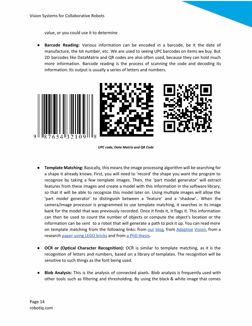
● Barcode Reading: Various information can be encoded in a barcode, be it the date of
manufacture, the lot number, etc. We are used to seeing UPC barcodes on items we buy. But
2D barcodes like DataMatrix and QR codes are also often used, because they can hold much
more information. Barcode reading is the process of scanning the code and decoding its
information. Its output is usually a series of letters and numbers.
UPC code, Data Matrix and QR Code
● Template Matching: Basically, this means the image processing algorithm will be searching for
a shape it already knows. First, you will need to ‘record’ the shape you want the program to
recognize by taking a few template images. Then, the ‘part model generator’ will extract
features from these images and create a model with this information in the software library,
so that it will be able to recognize this model later on. Using multiple images will allow the
‘part model generator’ to distinguish between a ‘feature’ and a ‘shadow’.. When the
camera/image processor is programmed to use template matching, it searches in its image
bank for the model that was previously recorded. Once it finds it, it flags it. This information
can then be used to count the number of objects or compute the object's location or the
information can be sent to a robot that will generate a path to pick it up. You can read more
on template matching from the following links: from our blog, from Adaptive Vision, from a
research paper using LEGO bricks and from a PhD thesis.
● OCR or (Optical Character Recognition): OCR is similar to template matching, as it is the
recognition of letters and numbers, based on a library of templates. The recognition will be
sensitive to such things as the font being used.
● Blob Analysis: This is the analysis of connected pixels. Blob analysis is frequently used with
other tools such as filtering and thresholding. By using the black & white image that comes
Page 14
robotiq.com

Vision Systems for Collaborative Robots
out of the thresholding algorithm, you should be able to easily analyze the shape of the blobs.
Further reading here.
Challenges of a Vision System for Template
Matching Now that you know how template matching works, you won't need to read every single article you
come across to understand its basic principles and it will be easier for you to understand what
constitutes a challenge for this kind of algorithm. Some of these challenges are discussed below.
Parts Overlap or Touch Each Other
Of course, non-overlapping parts will be easier to recognize than overlapping ones. This doesn’t mean
it’s impossible to detect overlapping parts, but it will be more of a challenge for the algorithm. So in
terms of reliability, you have more chance of recognizing non-overlapping parts every single time. For
overlapping parts, you might end up with contour detection that gives you multiple possibilities…
To understand this more clearly, let’s bring back a childhood memory: tangram puzzles. If I give you
an image of a tangram puzzle, and you have to guess what parts were assembled (and how) to arrive
at the following result, you might hesitate a bit between various possibilities.
So here we go:
Page 15
robotiq.com

Vision Systems for Collaborative Robots
This is the capital letter E, the result from an assembly of you don’t know how many pieces. What you
do know, however, is that it can be assembled using any of these pieces:
So which of these parts were used, and where are they located?
I’m sure you’re curious to know the answer, so here it is with more easily defined contours!
OK, I agree that the capital E example is hardly realistic. The parts are too perfectly assembled. It
would have been more realistic, if the parts overlapped each other and were less distinguishable.
Still, it illustrates how hard it can be to recognize shapes, even though you have a ‘library’ of known
shapes, and a picture of the current shapes you want to recognize. In this case, the parts were not
overlapping, they were just touching each other. But the contours were hard to determine.
Moreover, if there’s no contrast between the two parts, then the camera will have a hard time
Page 16
robotiq.com

Vision Systems for Collaborative Robots
determining which one is on top of the other, so the robot will not know which one to pick up first.
Insufficient Contrast
If you want to detect edges easily, or recognize a variation in the grayscale, you’ll obviously need a
good contrast. Therefore, the background for the parts should be as far away as possible (grayscale
speaking) from the parts themselves. Easily said: you want to recognize black parts? Use a white or
clear background.
The surface finish of the parts will also influence the contrast. If you have relatively dark grey metallic
parts, you might have opted for a white background. If the parts are shiny, there is a good chance that
they’ll reflect light back into the camera. Particularly if they are caught at a certain angle. So,
depending on the camera angle, you might end up with an almost white part (light has been reflected
back to the camera), a relatively dark part, or a mix of the two. This is another source of challenge for
template matching.
Outside Lighting Influence
If your part’s material is highly reflective, you will need to take into account lighting that comes from
outside of your vision system. That is, the sunshine coming in from a window, or light flashes coming
in from a nearby soldering process. And even if your part’s material is not that reflective, ambient
light changes could influence the shadows created in the background… So make sure you take this
into account, and read these tricks to cope with such problems.
Page 17
robotiq.com

Vision Systems for Collaborative Robots
Shadowing
Seeing an object and its shadow will create another visual challenge! This can still be managed, but it
might reduce the robustness of the part recognition program. It is important that the template image
you will be using is free from as much shadowing as possible in order to have the correct template
stored in your library. Otherwise, you might end up looking for a part plus its shadow and then the
program won’t find anything that resembles this, since the shadow will have changed. One way to
compensate for shadows at teaching time is to use multiple images of the same object, taken at
various angles. For example, you could take 1 image, rotate the part, take another image, etc. The
‘template image’ would then be built from a combination of all of these images.
Too Much Variations Between Parts
This is a crucial aspect of template creation and it harkens back to a blog post about OCR.
“Let’s look at an Optical Character Recognition (OCR) example: you have taught the system that the
pattern to be looked for is 8, but a B would also be okay because you know the left-hand side of the
character sometimes has problems being punched correctly. Now let’s say the machine reads a 3…
would that be acceptable? The left-hand side is different, but you have trained the system to be less
picky on this side, because of known punching problems... That’s a good example of desensitization:
the more various things you input into the system as “normal”, the less sensitive your system will
become.”
Page 18
robotiq.com

Vision Systems for Collaborative Robots
The example here is about the recognition of a specific letter, but the same rules apply to other
shapes. If you are too permissive at the teaching stage; the ‘template’ you will be looking for will be
less specific and the part recognition might be less reliable. If you have similar part models, you will
probably confuse a few of them.
Another example is deformable objects. Think of a bath towel that could be presented as either
folded or as a shapeless blob of cloth. You will have so many possible towel configurations that you
will probably end up identifying anything as a towel.
So what Do I Start with then? We definitely recommend starting slowly, so as to gain expertise and confidence from your first
experience.
Here are some tricks to ease into your first vision project:
● Start with a simple pick & place project.
● Use parts that have:
○ Few or no variations between parts from the same model, but great variations from
one model to another;
○ A distinct contour;
○ Recognizable features (e.g. drilled holes at specific and consistent spots);
○ A mat texture.
● Change the background if needed, so that you’ll have a great contrast between the part and
what’s behind it.
● Take control of the lighting, don’t place your system near a window or near a ceiling light that
could go on and off during the day. Test your system and see how it behaves.
Page 19
robotiq.com

Vision Systems for Collaborative Robots
● Place parts to be recognized so they have a gap between them (no overlapping, no touching).
● Pay special attention to the teaching phase. Treat different surface finishes as different shapes
to be taught.
If you start teaching your vision system with an easy challenge, you will get used to its parameters and
you will be able to experiment with what kinds of variations your system can tolerate. For example,
overlapping parts might turn out to be OK in your application, if the parts have features that are easy
to recognize by the system.
Some ideas if you’re ready to take it to the next level:
● If surrounding light or undesirable reflections really become a problem, you could…
○ “Hide” your system underneath a hood of some kind or use an opaque top and tinted
windows. So that the light you’ll get on your picture is really the one you want to use.
Don’t go through all this trouble if it’s not needed though, so test first and judge
afterwards!
○ Add another light source. You will need to control this additional equipment though
and synchronize it with the picture being taken. If, for example, you work with highly
reflective metallic parts, and are only interested in detecting their contours in order to
pick them up, you might find it easier to backlight the parts instead.
The principle of backlighting in photography: light source is placed behind the object, so the subject appears black on a light
background with an easily detectable contour.
● Upgrade from a simple pick & place automation to a “check & pick & classify” process by
verifying certain features. For example, check that a label has been applied to the object; put
it in tray A if it has a label, or in tray B if it doesn’t.
● Use your vision system for counting features or parts.
Page 20
robotiq.com

Vision Systems for Collaborative Robots
● Check for a specific shape, then flag any other shapes that might represent a defect. Play with
tolerances in order to properly adjust your system.
Conclusion We hope this article has provided you with some basic knowledge of machine vision and given you
some insights on choosing the correct device for your application. For more information please be
sure to check out Robotiq’s blog for other insightful articles related to machine vision and robotic
applications.
Page 21
robotiq.com

Vision Systems for Collaborative Robots
About Robotiq Robotiq’s mission is to free human hands from tedious tasks so companies and workers can focus
where they truly create value. Our grippers and sensors enhance robot application flexibility and
integration simplicity.
Our head office is located in Quebec City, Canada, while our products are sold and supported in more
than 30 countries through a network of highly capable channel partners.
Let’s Keep in Touch For any questions concerning robotic and automated handling or if you want to learn more about the
advantages of using flexible electric handling tools, contact us.
Join us on social media:
Robotiq’s Blog
Youtube
Google+
Page 22
robotiq.com

Vision Systems for Collaborative Robots
Other Interesting eBooks
Adding Extra Sensors How to Simplify a Complex Task
Take a look on DoF, where industrial automation Pros share their know-how and get answers
Page 23
robotiq.com