Vision-Based Loitering Over a Target for a Fixed-Wing … Loitering Over a Target for a Fixed-Wing...
7
Vision-Based Loitering Over a Target for a Fixed-Wing UAV Pietro Peliti Lorenzo Rosa Giuseppe Oriolo Marilena Vendittelli Dipartimento di Ingegneria Informatica, Automatica e Gestionale, Universit` a di Roma La Sapienza, via Ariosto 25, 00185, Roma, Italy (e-mail: {peliti,rosa,oriolo,vendittelli}@dis.uniroma1.it) Abstract: For a fixed-wing Unmanned Aerial Vehicle (UAV) equipped with a gimbaled camera, we consider the problem of tracking a visual target while simultaneously bringing the UAV to orbit on a circular trajectory centered above the target. To achieve this kind of loitering behavior, we propose a feedback control method that is inspired by image-based visual servoing and makes use of a backstepping technique. Through this approach, we are able to obtain a control law that requires only image and proprioceptive data. A formal proof of convergence and a set of validating numerical trials are provided, including a realistic simulation on a commercial UAV. Keywords: UAV, feedback control, visual servoing, target tracking, backstepping 1. INTRODUCTION Unmanned Aerial Vehicles (UAVs) are increasingly used in many applications including environment monitoring, search and rescue, surveillance, patrolling, and escorting. However, improving the autonomy of these systems is still a scientific challenge. Different kinds of UAVs are commercially available or have been designed for research purposes. They may differ in size, shape and actuation, resulting in different flight characteristics, but the sensing equipment invariably includes an Inertial Measurement Unit (IMU) and a camera. Fixed-wing UAVs are of partic- ular interest when efficiency and endurance is a concern. A typical task for a UAV is the continued observation ofa ground target, either selected by a remote human operator or automatically identified by the UAV itself. While a VTOL UAV can conveniently accomplish this by hovering above the target (Bourquardez et al., 2009), a fixed-wing UAV requires non-zero airspeed to fly and therefore must loiter along a suitable trajectory. In principle, one way to achieve loitering is to define a reference trajectory for the UAV in ground coordinates. This can be done if the position of the UAV and the relative position of the target w.r.t. the UAV are available. The first may be provided by a Global Positioning System (GPS) while the second can be reconstructed fusing visual and inertial data; in an escorting mission, or whenever it is collaborative, the target may even directly communicate its ground position to the UAV. Methods that can be classified in this category were proposed by Stolle and Rysdyk (2003) and Quigleyand et al. (2005) . In certain operative conditions, however, it may be prefer- able to adopt the visual servoing paradigm to design con- trol schemes that rely on image and proprioceptive data only (Chaumette and Hutchinson, 2006). This approach is computationally simpler and can be expected to provide a more reactive behavior, e.g., if the target is moving. More- over, it does not need GPS data, which may be unreliable or even unavailable, temporarily or permanently. Visual servoing methods can be classified as either position-based (PBVS) or image-based (IBVS). Using PBVS for loitering requires an estimate of the relative pose of the target with respect to the UAV. Tools like the Ex- tended Kalman Filter can be used to robustly estimate this information (Watanabe et al., 2009). Ma et al. (2010) and Theodorakopoulos and Lacroix (2008) presented PBVS strategies that use polar rather than cartesian coordinates and a visual measurement of the bearing angle between the target and the UAV. It is well known, however, that PBVS is sensitive to kinematic model errors, imprecise camera calibration and image noise. IBVS methods are a more robust alternative. For example, Chen and Dawson (2006) proposed an IBVS control strat- egy for the related problem of tracking a moving UAV. In the work of Le Bras et al. (2009), a control scheme based on spherical projection and optic flow is developed for the case of a UAV equipped with a fixed camera; convergence to a circular trajectory is enforced by a suitable definition of the visual task. In this paper, we consider a fixed-wing UAV equipped with a gimbaled camera flying above a target; our objective is to lead the UAV to orbit on a circular trajectory centered above the target. An advantage of this kind of loitering is to require zero roll rate at steady-state, at least in the absence of wind. Moreover, a circular trajectory allows to monitor the target from every side and is optimal for its localization (Ponda and Frazzoli, 2009). Our interest in this work is to investigate how circular loitering can be naturally produced by vision-based control laws that do not need inertial coordinate measurements. To this end, we adopt the IBVS approach to design a controller that uses visual and proprioceptive data only. 10th IFAC Symposium on Robot Control International Federation of Automatic Control September 5-7, 2012. Dubrovnik, Croatia 978-3-902823-11-3/12/$20.00 © 2012 IFAC 51 10.3182/20120905-3-HR-2030.00036
Transcript of Vision-Based Loitering Over a Target for a Fixed-Wing … Loitering Over a Target for a Fixed-Wing...

Vision-Based Loitering Over a Target
for a Fixed-Wing UAV
Pietro Peliti Lorenzo Rosa Giuseppe OrioloMarilena Vendittelli
Dipartimento di Ingegneria Informatica, Automatica e Gestionale,Universita di Roma La Sapienza, via Ariosto 25, 00185, Roma, Italy
(e-mail: peliti,rosa,oriolo,[email protected])
Abstract: For a fixed-wing Unmanned Aerial Vehicle (UAV) equipped with a gimbaled camera,we consider the problem of tracking a visual target while simultaneously bringing the UAV toorbit on a circular trajectory centered above the target. To achieve this kind of loitering behavior,we propose a feedback control method that is inspired by image-based visual servoing and makesuse of a backstepping technique. Through this approach, we are able to obtain a control lawthat requires only image and proprioceptive data. A formal proof of convergence and a set ofvalidating numerical trials are provided, including a realistic simulation on a commercial UAV.
Keywords: UAV, feedback control, visual servoing, target tracking, backstepping
1. INTRODUCTION
Unmanned Aerial Vehicles (UAVs) are increasingly usedin many applications including environment monitoring,search and rescue, surveillance, patrolling, and escorting.However, improving the autonomy of these systems isstill a scientific challenge. Different kinds of UAVs arecommercially available or have been designed for researchpurposes. They may differ in size, shape and actuation,resulting in different flight characteristics, but the sensingequipment invariably includes an Inertial MeasurementUnit (IMU) and a camera. Fixed-wing UAVs are of partic-ular interest when efficiency and endurance is a concern.
A typical task for a UAV is the continued observation of aground target, either selected by a remote human operatoror automatically identified by the UAV itself. While aVTOL UAV can conveniently accomplish this by hoveringabove the target (Bourquardez et al., 2009), a fixed-wingUAV requires non-zero airspeed to fly and therefore mustloiter along a suitable trajectory.
In principle, one way to achieve loitering is to define areference trajectory for the UAV in ground coordinates.This can be done if the position of the UAV and therelative position of the target w.r.t. the UAV are available.The first may be provided by a Global Positioning System(GPS) while the second can be reconstructed fusing visualand inertial data; in an escorting mission, or whenever it iscollaborative, the target may even directly communicateits ground position to the UAV. Methods that can beclassified in this category were proposed by Stolle andRysdyk (2003) and Quigleyand et al. (2005) .
In certain operative conditions, however, it may be prefer-able to adopt the visual servoing paradigm to design con-trol schemes that rely on image and proprioceptive dataonly (Chaumette and Hutchinson, 2006). This approach iscomputationally simpler and can be expected to provide a
more reactive behavior, e.g., if the target is moving. More-over, it does not need GPS data, which may be unreliableor even unavailable, temporarily or permanently.
Visual servoing methods can be classified as eitherposition-based (PBVS) or image-based (IBVS). UsingPBVS for loitering requires an estimate of the relative poseof the target with respect to the UAV. Tools like the Ex-tended Kalman Filter can be used to robustly estimate thisinformation (Watanabe et al., 2009). Ma et al. (2010) andTheodorakopoulos and Lacroix (2008) presented PBVSstrategies that use polar rather than cartesian coordinatesand a visual measurement of the bearing angle between thetarget and the UAV. It is well known, however, that PBVSis sensitive to kinematic model errors, imprecise cameracalibration and image noise.
IBVS methods are a more robust alternative. For example,Chen and Dawson (2006) proposed an IBVS control strat-egy for the related problem of tracking a moving UAV. Inthe work of Le Bras et al. (2009), a control scheme basedon spherical projection and optic flow is developed for thecase of a UAV equipped with a fixed camera; convergenceto a circular trajectory is enforced by a suitable definitionof the visual task.
In this paper, we consider a fixed-wing UAV equipped witha gimbaled camera flying above a target; our objective isto lead the UAV to orbit on a circular trajectory centeredabove the target. An advantage of this kind of loiteringis to require zero roll rate at steady-state, at least in theabsence of wind. Moreover, a circular trajectory allows tomonitor the target from every side and is optimal for itslocalization (Ponda and Frazzoli, 2009).
Our interest in this work is to investigate how circularloitering can be naturally produced by vision-based controllaws that do not need inertial coordinate measurements.To this end, we adopt the IBVS approach to design acontroller that uses visual and proprioceptive data only.
10th IFAC Symposium on Robot ControlInternational Federation of Automatic ControlSeptember 5-7, 2012. Dubrovnik, Croatia
978-3-902823-11-3/12/$20.00 © 2012 IFAC 51 10.3182/20120905-3-HR-2030.00036
target
Fig. 1. The UAV body frame Fb and the ground frame F .
In particular, it is first shown that regulation of the vi-sual features plus the pan angle to a suitable set-pointentails convergence to the desired kind of trajectory; then,such regulation is achieved for a simplified model of theUAV+camera system with direct yaw control; finally, thesame behavior is obtained for the original UAV+camerasystem through backstepping. Enhancements to the ba-sic scheme are proposed, including the enforcement of adesired radius for the circular trajectory, a simplified rollcontrol technique, and the integration of an estimator tomake sure that the depth of the visual target is not neededfor implementation. Simulations are presented for both theideal UAV dynamics used for design and for a realisticmodel of a commercial UAV.
The paper is organized as follows. In Sect. 2 a model ofthe UAV+camera system is introduced, while in Sect. 3the loitering problem is formulated. Our control methodis presented in Sect. 4 and validated through preliminarysimulations in Sect. 5. Improvements to the basic schemeare discussed in Sect. 6. Section 7 reports simulationresults for the full nonlinear model of an Aerosonde UAV,while Sect. 8 hints at possible future work.
2. MATHEMATICAL MODEL
Consider the fixed-wing UAV in Fig. 1, with the bodyframe Fb attached to its center of gravity. Generalizedcoordinates are the cartesian coordinates (x, y, z) of theorigin of Fb in a ground frame F , plus the orientation ofFb w.r.t. F , parameterized through the Euler angles ZYX(ψ, θ, φ), i.e., the UAV yaw, pitch and roll angles.
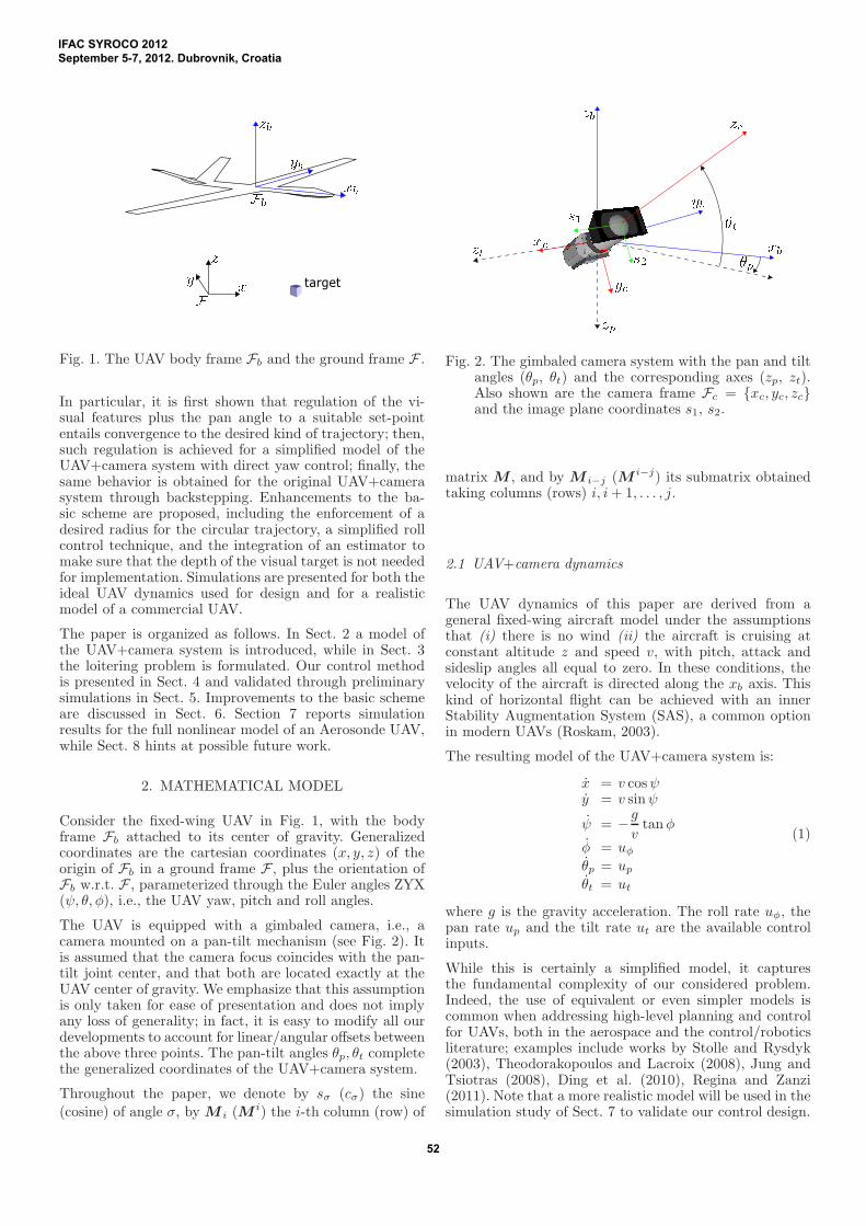
The UAV is equipped with a gimbaled camera, i.e., acamera mounted on a pan-tilt mechanism (see Fig. 2). Itis assumed that the camera focus coincides with the pan-tilt joint center, and that both are located exactly at theUAV center of gravity. We emphasize that this assumptionis only taken for ease of presentation and does not implyany loss of generality; in fact, it is easy to modify all ourdevelopments to account for linear/angular offsets betweenthe above three points. The pan-tilt angles θp, θt completethe generalized coordinates of the UAV+camera system.
Throughout the paper, we denote by sσ (cσ) the sine
(cosine) of angle σ, by M i (M i) the i-th column (row) of
Fig. 2. The gimbaled camera system with the pan and tiltangles (θp, θt) and the corresponding axes (zp, zt).Also shown are the camera frame Fc = xc, yc, zcand the image plane coordinates s1, s2.
matrix M , and by M i−j (M i−j) its submatrix obtainedtaking columns (rows) i, i+ 1, . . . , j.
2.1 UAV+camera dynamics
The UAV dynamics of this paper are derived from ageneral fixed-wing aircraft model under the assumptionsthat (i) there is no wind (ii) the aircraft is cruising atconstant altitude z and speed v, with pitch, attack andsideslip angles all equal to zero. In these conditions, thevelocity of the aircraft is directed along the xb axis. Thiskind of horizontal flight can be achieved with an innerStability Augmentation System (SAS), a common optionin modern UAVs (Roskam, 2003).
The resulting model of the UAV+camera system is:
x = v cosψy = v sinψ
ψ = −g
vtanφ
φ = uφθp = upθt = ut
(1)
where g is the gravity acceleration. The roll rate uφ, thepan rate up and the tilt rate ut are the available controlinputs.
While this is certainly a simplified model, it capturesthe fundamental complexity of our considered problem.Indeed, the use of equivalent or even simpler models iscommon when addressing high-level planning and controlfor UAVs, both in the aerospace and the control/roboticsliterature; examples include works by Stolle and Rysdyk(2003), Theodorakopoulos and Lacroix (2008), Jung andTsiotras (2008), Ding et al. (2010), Regina and Zanzi(2011). Note that a more realistic model will be used in thesimulation study of Sect. 7 to validate our control design.
IFAC SYROCO 2012September 5-7, 2012. Dubrovnik, Croatia
52

2.2 Visual feature kinematics
Consider now a visual point feature associated to thestationary target of interest 1 . Let s = (s1 s2)
T be thefeature coordinates on the image plane xc, yc and Z thetarget depth. The velocity of the feature point is obtainedfrom the velocity (vc ωc)
T of the camera in its frame Fcas
s = J i(s, Z)
(
vc
ωc
)
, (2)
where J i is the so-called interaction matrix (Chaumetteand Hutchinson, 2006).
A simple computation shows that the camera velocity isin turn related to the UAV+camera generalized velocitiesby the relationship
(
vc
ωc
)
= Jc(ψ, φ, θp, θt)
xy
ψ
φ
θpθt
(3)
in which
Jc =
(
Rc,1−2 O3×4
O3×2 RcΩ
)
,
where Rc is the rotation matrix from F to Fc and
Ω =
0 cψ −sψsφ sψcφcθp− cψsθp
0 sψ cψsφ −cψcφcθp− sψsθp
1 0 −cφ −sφcθp
.
The above expressions are obtained by considering thatthe UAV vertical velocity z and pitch angle θ are bothidentically zero in the flight condition of interest.
Putting together eqs. (2) and (3), the visual featurekinematics can be written as
s = J i(s, Z)Jc(ψ, φ, θp, θt)
xy
ψ
φ
θpθt
. (4)
3. PROBLEM FORMULATION
Our objective is to devise a control strategy that willmove the UAV along a circular trajectory centered abovethe target and simultaneously keep the observed target atthe center of the image. For the reasons discussed in theintroduction, we would like to achieve this behavior usingvisual data provided by the camera and proprioceptiveinformation coming from the UAV inertial navigationsystem and the pan-tilt joint encoders. We will also assumethat a measurement of the UAV speed v is available. Inpractice, this may be obtained via a Pitot tube, computedfrom GPS data or reconstructed from optical flow (Le Braset al., 2009).
1 The important problem of how to choose, extract and track sucha feature is outside the scope of this paper; we refer the readerto the pertinent publications in computer vision, such as the oneby Drummond and Cipolla (2002).
Fig. 3. If the UAV+camera system keeps the target at thecenter of the image plane and the pan angle θp at±π/2, then it is necessarily moving along a circulartrajectory centered above the target.
A basic observation is that a purely visual definition ofthe task is not sufficient to enforce the desired UAVmotion. In fact, using the additional degrees of freedomof the pan-tilt platform, the target can be kept at thecenter of the image (i.e., s ≡ 0) with the UAV movingalong an infinity of trajectories, some of them not evenclosed. However, this difficulty can be solved by extendingthe visual task with the value of the pan angle. In fact,simple geometric arguments can be used to prove that theonly UAV+camera motion compatible with maintainingthe set-point s = 0, θp = ±π/2 is a clockwise orcounterclockwise circular trajectory centered above thetarget (see Fig. 3). Hence, regulation to this set-point willproduce the desired loitering behavior. In addition, thechosen outputs s and θp satisfy the requirement of beingfully computable from visual or proprioceptive data.
4. CONTROL APPROACH
As stated in the previous section, our objective is now todrive the visual features s to zero and the pan angle θpto π/2 (a clockwise sense of rotation has been chosen). Infact, regulation of these variables will automatically leadthe UAV to a circular trajectory. From a control viewpoint,the dynamics of our UAV+camera system are given byeq. (1), with uφ, up and ut as control inputs, while s andθp are the output variables.
Since our output vector is actually a simple extensionof a visual task, we adopt the classical visual servoingapproach based on input-output feedback linearization.This requires the differential map between the outputs andthe inputs, which can be derived as follows. Letting
G(ψ) =
cosψsinψ
O2×4
O4×1 I4×4
,
and dropping all dependencies, we can rewrite eq. (4) as
s = J i Jc G
v
ψ
φ
θpθt
= J
v
ψ
φ
θpθt
,
IFAC SYROCO 2012September 5-7, 2012. Dubrovnik, Croatia
53

having set J = J i Jc G. The above expression can also bewritten as
s = J1−2
(
v
ψ
)
+ J3−5
(
uφuput
)
. (5)
The complete input-output differential map is therefore
(
s
θp
)
=
(
J1−2
0 0
)(
v
ψ
)
+
(
J3−5
0 1 0
)
(
uφuput
)
, (6)
which is affine in the control inputs (the first term of therhs is a drift). If the matrix multiplying the input vector(the so-called decoupling matrix) were invertible, we couldperform feedback linearization to obtain a control law thatguarantees exponential convergence of s and θp to theirset-point. However, one may verify that such matrix issingular exactly at the set-point 2 .
In view of the above difficulty, we take a different, two-stepapproach to design our control law. In the first step, weconsider a modified dynamic model which differs from (1)in that it assumes direct, independent control of the yawangle. A visual control law for this modified system iseasily obtained via input-output feedback linearization. Inthe second step, this control law is used to generate the rollrate uφ for the actual UAV via a backstepping procedure.These two steps are detailed in the following.
4.1 Control of a modified UAV+camera dynamics
Consider the following UAV+camera dynamic model
x = v cosψy = v sinψ
ψ = uψφ = uφθp = upθt = ut.
(7)
This model differs from (1) because the yaw rate is anindependent input. To emphasize this, we call this system aunicycle-like UAV+camera. Note that the roll rate φ = uφis now assumed to be a known exogenous signal which wecannot manipulate (a disturbance rather than a control).
For the unicycle-like UAV+camera, the expression of thevisual feature velocity s given by (5) should be reorganizedas
s = ( J1 J3 )
(
v
φ
)
+ ( J2 J4 J5 )
(
uψuput
)
.
The drift term now depends on v and φ, rather than ψ,and the new input vector (with uψ in place of uφ) appearsin the second term. The complete input-output differentialmap is therefore given by
2 The physical reason behind this singularity is simple: when s = 0
and θp = π/2, keeping s at zero requires the compensation of thedrift term in (6). However, with the pan angle θp fixed at its set-point,such compensation would need instantaneous yaw control, which isnot available in the UAV+camera system (1).
(
s
θp
)
=
(
J1 J3
0 0
)(
v
φ
)
+
(
J2 J4 J5
0 1 0
)
(
uψuput
)
= JA
(
v
φ
)
+ JB
(
uψuput
)
. (8)
One may show that JB, the decoupling matrix for theunicycle-like UAV+camera, is full-rank 3 at the set-point.Hence, introducing the error vector e = (s θp − π/2)T ,and letting
(
uψuput
)
= −J−1
B
(
Ke + JA
(
v
φ
))
, (9)
with K a 3× 3 positive definite diagonal matrix, we guar-antee e = −Ke, i.e., decoupled exponential convergenceto the set-point (and hence, to a circular trajectory aroundthe target) for the unicycle-like UAV+camera.
4.2 Backstepping to the original UAV+camera dynamics
The original UAV+camera system (1) does not have directcontrol of the yaw angle: the latter can only be changedthrough the roll rate (see the third equation of the model).The idea is therefore to design uφ so as to guarantee that
the actual yaw rate ψ of (1) converges to the virtual yawcontrol uψ of (7), as given by the first equation in (9). Thiscan be done using a backstepping technique (Sepulchreet al., 1996). The pan and tilt rates, respectively givenby the second and third equation in (9), can instead bedirectly realized by the original UAV+camera system.
The error dynamics for the original UAV+camera sys-tem (1) is (compare with (8))
e =
(
s
θp
)
= JA
(
v
φ
)
+ JB
−g
vtanφ
uput
.
Adding and subtracting the term JB (uψ up ut )T to
the right-hand-side we get
e = JA
(
v
φ
)
+ JB
(
uψuput
)
+ JB
(
ξ00
)
, (10)
whereξ = −
g
vtanφ− uψ
is the mismatch between the actual yaw rate and thevirtual yaw control. Its time derivative is
ξ = −g
v
1
cos2 φφ− uψ = −
g
v
1
cos2 φuφ − uψ = w, (11)
with w an auxiliary input related to the actual input uφ.
Since (uψ up ut)T has been chosen as in (9), the sum of
the first two terms in the right-hand-side of (10) is equalto −Ke:
e = −Ke + ξ JB,1. (12)
We can now prove the following result.
3 It can also be shown that JB has a singularity when the targetis exactly below the UAV center of gravity. However, since the UAVmoves with a nonzero speed v, it will automatically drive away fromthe singularity. This, plus the use of a singularity-robust inverse ofJB , will be sufficient to guarantee that the control law (9) is alwayswell defined.
IFAC SYROCO 2012September 5-7, 2012. Dubrovnik, Croatia
54

Proposition 1. Choosing the auxiliary input w in (11) as
w = −eTJB,1 − kξ ξ, kξ > 0, (13)
yields exponential convergence of ξ to zero (i.e., of ψ to uψ)and of s, θp to the desired set-point. Hence, the UAV willasymptotically move along the desired circular trajectory.
Proof. Consider the following Lyapunov-like function
V =1
2eTe +
1
2ξ2,
whose time derivative along the trajectories of the systemis
V = eTe + ξ ξ = −e
TKe − kξξ
2,where we have used eqs. (11), (12) and (13). This impliesthe thesis.
The actual roll rate uφ is computed from (11) and (13) as
uφ =v
gcos2 φ (eTJB,1 + kξ ξ − uψ), (14)
where the signal uψ is given by the first equation in (9)
uψ = −(J−1
B K)1e + J1
A
(
v
φ
)
. (15)
The pan and tilt rates are instead directly given by thesecond and third equation in (9).
Due to the fact that system (1) is not in a strict feedbackform (Sepulchre et al., 1996), there are in principle twoproblems when implementing the control law (14–15) forthe roll rate. In fact, differentiating uψ and plugging the
result into (14) both φ and φ appear in the right-hand-side. Hence, an algebraic loop arises; moreover, the controllaw is non-causal. The first problem can be solved byusing a small time delay T equal to the sampling time,i.e., using the last available sample uφ(t − T ) for φ(t).
Causality is then recovered by replacing φ(t) with itsdirty derivative, computed by stable numerical filtering ofuφ = φ. Clearly, these approximations are only relevant
during the transient phase, as φ and φ are both zero atsteady-state.
5. PRELIMINARY SIMULATION
Preliminary simulation of our visual loitering scheme hasbeen performed in MATLAB. The UAV+camera systemobeys the dynamics (1), with z = 10 m and v = 10 m/s; apinhole camera model is used for image formation.
A typical simulation is the following. With the target fixedw.l.o.g. at the origin of the ground frame, the UAV startsfrom
(x0, y0, ψ0, φ0, θp0, θt0) = (20,−10,3
2π, 0,
2
3π,−
π
4)
and moves under the action of the control law (14–15) withgains K = diag0.5, 0.5, 10 and kξ = 1. The results areshown in Fig. 4. The top-left plot shows the UAV (triangle)trajectory seen from above, with the crosshair showing theposition of the target. As expected, the UAV achieves thedesired loitering behavior. The exponential convergenceof s and θp to their set-point is shown in the top-rightand bottom-left plots, respectively, whereas the bottom-right plot confirms that the actual yaw rate ψ of the UAVconverges to the virtual yaw control uψ of the unicycle-likeUAV thanks to the backstepping procedure.
UAV x-y trajectory [m]
-30 -15 0 15 30
-30
-15
0
15
30
visual features vs. time
s1
s2
0 5 10 15 20
0
-0.4
-0.3
-0.2
-0.1
pan angle [rad] vs. time
0 5 10 15 20
π2
3
4π
ξ [rad/s] vs. time
0 5 10 15 20
-0.4
-0.2
0
0.2
0.4
0.6
0.8
Fig. 4. Basic visual loitering: Simulation on model (1).
6. ENHANCEMENTS TO THE BASIC SCHEME
The simulation results of the previous section confirmthe effectiveness of our loitering scheme. However, somefurther improvements are possible.
6.1 Enforcing a desired radius
The radius of the circular trajectory to which the UAVconverges under control (14–15) changes with the initialcondition of the system. The possibility of enforcing adesired radius may be welcome in practice. To this end,consider that if the steady-state trajectory is circular thenits radius is given by ρ∞ = v/ψ∞. Hence, one may imposea desired radius ρd by achieving an asymptotic yaw rate
ψd =v
ρd.
The idea is therefore to inject this term as a feedforwardcommand in the virtual yaw control uψ of the unicycle-likeUAV+camera model. To make room for this additionaltask, we modify our control approach in a task-prioritysense (Chiaverini et al., 2009) as follows:
(
uψuput
)
=−(J1−2
B )†(
Kss+J1−2
A
(
v
φ
))
+P
ψd
kp
(π
2− θp
)
0
(16)where (J1−2
B )† is the pseudoinverse matrix of J1−2
B , P =
(I − (J1−2
B )†J1−2
B ) is the orthogonal projection matrix inits null space, Ks is a 2 × 2 positive definite diagonalmatrix, and kp > 0. Compared with (9), the modifiedcontrol law (16) considers only the visual features s asa primary task to be regulated to zero, whereas thesecondary task (leading the pan angle to π/2 and theyaw rate to the desired constant value) is executed asaccurately as possible without disturbing the primary.In other words, by this approach we have artificiallyintroduced a single degree of redundancy in the system,which is exploited to achieve a combined secondary task.
IFAC SYROCO 2012September 5-7, 2012. Dubrovnik, Croatia
55

UAV x-y trajectory [m]
-200 -100 0 100 200
-200
-100
0
100
200
visual features vs. time
s1
s2
0 20 40 60 80 100-0.6
-0.5
-0.4
-0.3
-0.2
-0.1
0
pan angle [rad] vs. time
0 100 200 300
π3
π2
radius [m] vs. time
0 100 200 300
200
150
Fig. 5. Enhanced visual loitering: Simulation on anAerosonde UAV.
6.2 An alternative to backstepping: Linear roll control
A computationally simpler alternative to the roll ratecontroller (14) based on backstepping is the following. Ateach time instant, the virtual yaw control uψ, given bythe first equation of (9) (or of (16) if a specific radius isenforced), is converted to a current desired value φ for theroll angle using the following formula
φ = arctan
(
−uψv
g
)
, (17)
which is directly derived from the third equation ofmodel (1). The roll rate can then be generated via a low-level linear control loop
uφ = kφ(φ− φ), kφ > 0. (18)
6.3 Estimating the target depth
The above visual loitering method (in all its versions)needs the feature depth Z for computing the interactionmatrix J i in (2). In principle, Z could be computed fromthe configuration of the UAV+camera system, includingthe UAV coordinates, and the coordinates of the target.This is in fact the method used in the previous simulations.However, our control approach has been to avoid alto-gether the use of inertial information. An effective solutionis to estimate Z from the evolution of the visual featuresduring the motion. To this end, one can directly use thenonlinear observer proposed by De Luca et al. (2008).
7. SIMULATION ON AN AEROSONDE UAV
Simulations of the modifications of the last section (radiusenforcing, linear roll control, depth estimation) on theideal model (1) confirm that each of them is effective.They are omitted here for lack of space but available athttp://www.dis.uniroma1.it/~labrob/research/FWIBVS.html.
In this section, we present a realistic simulation whichshows the performance of our visual hovering method (in-
UAV x-y trajectory [m]
-200 -100 0 100 200
-200
-100
0
100
200
measured vis. features vs. time
s1
s2
0 20 40 60 80 100-0.6
-0.5
-0.4
-0.3
-0.2
-0.1
0
0.1
0.2
pan angle [rad] vs. time
0 100 200 300
π3
π2
radius [m] vs. time
0 100 200 300
200
150
Fig. 6. Enhanced visual loitering: Simulation on anAerosonde UAV in the presence of image noise andwind.
cluding all three modifications above) on a more completeUAV model. In particular, we have used the simulatorof the Aerosonde UAV (http://www.aerosonde.com) includedin the Aerosim Blockset by Unmanned Dynamics LLC.To this accurate simulator, which includes aerodynamiceffects, we have added low level control loops aimed atimproving the adherence of the model to the assumptionsof Sect. 2. In particular, airspeed and altitude hold controlmodes have been implemented via the control of elevatorand throttle. The roll rate reference uφ produced by theloitering controller is tracked using a linear control loopon the ailerons, while the rudder is used to achieve coor-dinated turn with sideslip angle close to zero.
The simulation starts from the initial conditions
(x0, y0, z0, ψ0, φ0, θp0, θt0)=(200, 100, 100,3
2π, 0,
π
3,−
π
4),
with a reference airspeed v = 25 m/sec and a feedforward
yaw rate ψd in (16) of 0.15 rad/sec, corresponding to adesired loitering radius of 166.6 m. The target featuredepth Z is estimated through the previously mentionednonlinear observer. The results are shown in Fig. 5.
Even for this realistic model, the visual features convergeto zero and the UAV asymptotically loiters on a circulartrajectory above the target. Both the pan angle and theloitering radius exhibit a small steady-state error withrespect to the desired values (respectively 0.5% and 4%).This mismatch is mainly due to the sideslip and pitchangles being (small but) not zero at steady state. Inparticular, the nonzero pitch angle is needed to fly atthe desired airspeed in view of the realistic simulation ofthe aerodynamics. As a consequence, the steady-state panangle required to keep the target at the center of the imageplane is also slightly different from π/2.
To test the robustness of the proposed visual loiteringmethod, we have run the same simulation under perturba-tions. In particular, we add a zero-mean gaussian random
IFAC SYROCO 2012September 5-7, 2012. Dubrovnik, Croatia
56

disturbance with 0.01 variance on each visual feature tosimulate camera noise. Moreover, a strong constant windof 8 m/s (about 30% of the aircraft speed) blows alongthe x axis 4 . The results, reported in Fig. 6, show that theUAV trajectory is slightly deformed and its center is alsodisplaced. The loitering behavior is however guaranteedtogether with visual target tracking.
We consider these results to be encouraging given theaccuracy of the UAV simulated model. In addition,we have obtained equivalent results when the target isslowly moving. Clips from all simulations are available athttp://www.dis.uniroma1.it/~labrob/research/FWIBVS.html.
8. CONCLUSIONS
We have presented a control method for driving a UAVequipped with a gimbaled camera to a circular trajectorycentered above a ground target using only visual and pro-prioceptive data. To this end, we have used an IBVS-likeapproach. In particular, it was first shown that regulationof the visual features plus the pan angle to a suitable set-point entails convergence to the desired kind of trajectory;then, such regulation was achieved for a simplified model ofthe UAV+camera with direct yaw control; and finally, thesame behavior was obtained for the original UAV+camerasystem through backstepping. Improvements to this basicscheme are possible, including the enforcement of a desiredradius for the circular trajectory, a simplified roll controltechnique, and the integration of a visual depth estimatorto make sure that the relative position of the camera w.r.t.the target is not needed for implementation. Simulationresults, both for the ideal model and a more realistic case,have been presented to illustrate the performance androbustness of the proposed loitering method.
Future work will address several points, such as main-taining the target in the camera field of view. With thecontrol law (9), a decoupled exponential convergence of s
is obtained for the unicycle-like UAV+camera, thus guar-anteeing that the target will never leave the field of viewduring the transient. The same is true for the modifiedcontrol law (16). However, this does not necessarily holdfor the actual UAV+camera system, whose actual yaw rateψ is different from uψ during the transient phase. While wenever experienced target view loss in simulations, it wouldbe desirable to introduce this constraint explicitly in thebackstepping design. We are also planning to implementthe proposed method on an actual RC-sized aircraft toperform a more accurate assessment of its robustness.
REFERENCES
Bourquardez, O., Mahony, R., Guenard, N., Chaumette,F., Hamel, T., and Eck, L. (2009). Image-based visualservo control of the translation kinematics of a quadro-tor aerial vehicle. IEEE Trans. on Robotics, 25(3), 743–749.
4 The perturbation introduced by the wind is actually twofold. First,it acts on the UAV disturbing its motion. Second, the airspeedmeasured by the on-board sensors is different from the actual groundspeed, and this means that the controller uses the former in place ofthe (correct) latter.
Chaumette, F. and Hutchinson, S. (2006). Visual servocontrol, Part I: Basic approaches. IEEE Robotics andAutomation Mag., 13(4), 82–90.
Chen, J. and Dawson, D. (2006). UAV tracking with amonocular camera. In 45th IEEE Conf. on Decisionand Control, 3873–3878.
Chiaverini, S., Oriolo, G., and Walker, I. (2009). Chap-ter 11: Kinematically redundant manipulators. InO. Khatib and B. Siciliano (eds.), Handbook of Robotics,245–268. Springer.
De Luca, A., Oriolo, G., and Robuffo Giordano, P. (2008).Feature depth observation for image-based visual servo-ing: Theory and experiments. The Int. J. of RoboticsResearch, 27(10), 1093–1116.
Ding, X.C., Rahmani, A., and Egerstedt, M. (2010). Multi-UAV convoy protection: An optimal approach to pathplanning and coordination. IEEE Trans. on Robotics,26(2), 256–268.
Drummond, T. and Cipolla, R. (2002). Real-time visualtracking of complex structures. IEEE Trans. on PatternAnalysis and Machine Intelligence, 24(7), 932 –946.
Jung, D. and Tsiotras, P. (2008). Bank-to-turn controlfor a small UAV using backstepping and parameteradaptation. In 17th IFAC World Congress, 4406–4411.
Le Bras, F., Hamel, T., and Mahony, R. (2009). Image-based visual servo control for circular trajectories for afixed-wing aircraft. In 48th IEEE Conf. on Decision andControl, 3430–3435.
Ma, L., Cao, C., Hovakimyan, N., Dobrokhodov, V., andKaminer, I. (2010). Adaptive vision-based guidancelaw with guaranteed performance bounds. Journal ofGuidance, Control, and Dynamics, 33(3), 834–852.
Ponda, S. and Frazzoli, E. (2009). Trajectory optimizationfor target localization using small unmanned aerialvehicles. In AIAA Guidance, Navigation, and ControlConf.
Quigleyand, M., Goodrich, M.A., Griffiths, S., Eldredge,A., and Beard, R.W. (2005). Target acquisition, local-ization, and surveillance using a fixed-wing mini-UAVand gimbaled camera. In 2005 IEEE Int. Conf. onRobotics and Automation, 2600–2605.
Regina, N. and Zanzi, M. (2011). UAV guidance law forground-based target trajectory tracking and loitering.In 2011 IEEE Aerospace Conference, 1–9.
Roskam, J. (2003). Airplane Flight Dynamics and Auto-matic Flight Controls, Part II. DARcorporation.
Sepulchre, R., Jankovic, M., and Kokotovic, P. (1996).Constructive Nonlinear Control. Springer.
Stolle, S. and Rysdyk, R. (2003). Flight path followingguidance for unmanned air vehicles with pan-tilt camerafor target observation. In 22nd Digital Avionics SystemsConference, volume 2, 8.B.3.1–12.
Theodorakopoulos, P. and Lacroix, S. (2008). A strategyfor tracking a ground target with a UAV. In 2008IEEE/RSJ Int. Conf. on Intelligent Robots and Sys-tems, 1254–1259.
Watanabe, Y., Fabiani, P., and Le Besnerais, G. (2009).Simultaneous visual target tracking and navigation ina GPS-denied environment. In 14th Int. Conf. onAdvanced Robotics, 1–6.
IFAC SYROCO 2012September 5-7, 2012. Dubrovnik, Croatia
57