Vision™ 2.0 User Manual - Gammill...
116
Vision™ 2.0 User Manual Gammill, Inc. |March 2014
Transcript of Vision™ 2.0 User Manual - Gammill...

Vision™ 2.0 User Manual
Gammill, Inc. |March 2014

Gammill, Inc. 2

Vision™ 2.0
User Manual

IMPORTANT MACHINE INFORMATION It is our goal to ensure that Customers have information on the tools and accessories (standard and optional), that are available for use with Gammill® quilting machines. Some of the tools and accessories detailed in this Manual may be optional equipment. We recommend that you consult with your Authorized Gammill Dealer or Sales Representative for the most current list of standard and optional equipment. Standard equipment, optional equipment, and pricing are subject to change without notice.
Copyright © 2014 Gammill, Inc. All Rights Reserved
PN140-0004 Rev00
March 2014
All rights reserved. No parts of this work may be reproduced in any form or by any means – graphic, electronic, or mechanical, including photocopying, recording, taping, or information storage and retrieval systems – without the written permission of the publisher.
Products that are referred to in this document may be either trademarks and/or registered trademarks of the respective owners. The publisher and the author make no claim to these trademarks.
While every precaution has been taken in the preparation of this document, the publisher and the author assume no responsibility for errors or omissions, or for damages resulting from the use of information contained in this document or from the use of programs and source code that may accompany it. In no event shall the publisher and the author be liable for any loss of profit or any other commercial damage caused or alleged to have been caused directly or indirectly by this document.
PN140-0004 Rev00 Vision™ 2.0 User Manual 2

TABLE OF CONTENTS
Vision™ 2.0 Front View .......................................................................................................................................... 6
Vision™ 2.0 Right Side View .................................................................................................................................. 7
Vision™ 2.0 Left Side View .................................................................................................................................... 9
Vision™ 2.0 Back View ......................................................................................................................................... 10
Oiling Routine .......................................................................................................................................................11
Threading Guide .................................................................................................................................................. 13
Using the On-board Bobbin Winder ..................................................................................................................... 19
The Bobbin Case .................................................................................................................................................. 22
Inserting the Bobbin Case ................................................................................................................................ 24
Setting the Tension .............................................................................................................................................. 25
Setting the Intermittent Tension ...................................................................................................................... 25
Setting the Rotary Tension............................................................................................................................... 26
Setting the Bobbin Case Tension ...................................................................................................................... 27
Checking the Top Thread Tension .................................................................................................................... 28
Pulling up the Thread ........................................................................................................................................... 29
Ending the Thread ............................................................................................................................................ 29
Loading the Quilt ................................................................................................................................................. 30
Adjusting the Table .............................................................................................................................................. 33
The Tablet ........................................................................................................................................................... 35
The Vision™ 2.0 Application ................................................................................................................................ 36
Stitching .............................................................................................................................................................. 40
Stitching Modes ................................................................................................................................................... 41
Constant Mode ................................................................................................................................................ 41
Regulate Mode ................................................................................................................................................ 42
Coast Regulate Mode ....................................................................................................................................... 44
Baste Mode ...................................................................................................................................................... 46
My Stitch™ Presets .............................................................................................................................................. 48
My Stitch™ Buttons ............................................................................................................................................. 50
Automatic Tie-Off Function ................................................................................................................................. 52
Stitch Timer Function .......................................................................................................................................... 57
Stitch Counter Function ....................................................................................................................................... 59
Bobbin Gauge Function ........................................................................................................................................ 61
Connection Information ....................................................................................................................................... 65
PN140-0004 Rev00 Vision™ 2.0 User Manual 3

Needle Stop Position ........................................................................................................................................... 66
Horizontal Channel Lock ...................................................................................................................................... 67
Vertical Channel Lock .......................................................................................................................................... 68
Laser .................................................................................................................................................................... 69
Additional Features - Future Enhancements ......................................................................................................... 71
Main Menu ........................................................................................................................................................... 72
Settings and other Screens .................................................................................................................................. 74
General Navigation .......................................................................................................................................... 74
Gammill Vision 2 .............................................................................................................................................. 75
About this App & Updates ................................................................................................................................ 75
Alerts ............................................................................................................................................................... 81
Needle Settings ............................................................................................................................................... 84
Laser Settings .................................................................................................................................................. 86
Display Settings ............................................................................................................................................... 89
Bluetooth Setup ............................................................................................................................................... 91
Quick Start Guide ............................................................................................................................................. 93
Service & Maintenance Screens ....................................................................................................................... 94
Navigation ................................................................................................................................................... 94
Buttons & Sensors ........................................................................................................................................ 96
Motor Operation .......................................................................................................................................... 99
Communications ........................................................................................................................................ 104
Oiling ......................................................................................................................................................... 108
Needle Position ........................................................................................................................................... 112
PN140-0004 Rev00 Vision™ 2.0 User Manual 4

! WARNING
F Risk for electric shock or burn. Unplug machine before removing any machine covers.
6 Heavy weight. Some components are heavy. A minimum of two people should lift the head, table parts, or any other large components to prevent injury.
! CAUTION
:
Moving needle and hopping foot can cause injury. Keep body parts and loose clothing away.
{ Pinch points. It is possible to pinch hands and fingers. Be alert and keep hands clear.
~
Rotating parts can cause injury. Keep hair, body parts, and loose clothing away.
C
Laser radiation. Avoid direct exposure to beam.
PN140-0004 Rev00 Vision™ 2.0 User Manual 5

VISION™ 2.0 FRONT VIEW
Part What it does
Front Handles The handles are equipped with toggle switches allowing four function selections. The functions of the handles can be customized to your preferred settings.
Light Embedded in the handles, the light illuminates the quilting area with natural (LED) or black light (UV).
Presser Bar The presser bar holds the hopping foot and controls the hopping foot height and stroke.
Hopping Foot The hopping foot maintains the needle and fabric distance to create good stitches. The shape makes it safe to guide the machine along the edge of a template or ruler.
Tablet The tablet contains the Vision 2.0 Android application allowing you to communicate with your machine.
Needle Bar The needle bar holds the needle and maintains the needle height to create good stitches.
Needle The needle carries the thread through the fabric.
Tablet
Handles
Light
Needle Bar
Needle
Presser Bar
Hopping Foot
PN140-0004 Rev00 Vision™ 2.0 User Manual 6

VISION 2.0 RIGHT SIDE VIEW
Part What it does
Take-Up Lever The take-up lever pulls the slack in the thread caused by it going around the bobbin.
Rotary Tension The rotary tension is a fine adjustment to achieve exactly the tension needed.
Thread Guides The thread guides hold the thread in place to prevent thread breaks.
Bobbin Area The bobbin area houses the bobbin, bobbin case and hook assembly.
Thread Break Sensor The thread break sensor measures thread movement and alarms when thread movement stops.
Intermittent Tension The intermittent tension applies a different amount of tension at different parts of the stitch to allow a wider variety of thread types to be used.
Thread Cone Holder The thread cone holder securely holds the cone of thread to feed thread to the machine for stitching.
Power Switches Thread Break
Sensor
Motor
Thread Cone Holder Bobbin Area
Rotary Tension
Thread Guide
Take-up Lever
Intermittent Tension
Rear Handles
PN140-0004 Rev00 Vision™ 2.0 User Manual 7

Rear Handles The rear handles offer control from the back of the machine; typically used for pantograph quilting.
Motor The motor powers the stitching mechanisms.
Power Switches The power switches are used to power the machine on/off.
PN140-0004 Rev00 Vision™ 2.0 User Manual 8

VISION™ 2.0 LEFT SIDE VIEW
Part What it does
Bobbin Winder The bobbin sits on a post that spins when the machine is running, filling a bobbin.
Laser Light The laser light in the front position, held in place by an adjustable laser clamp to aid in following stencils and block patterns.
Horizontal Channel Lock (H-Lock)
An electromagnet attached to the side of the machine that locks on the cross track allowing movement only in the left-right direction.
Y Encoder Device that measure movement in the forward-back direction.
X Encoder Device that measures movement in the left-right direction.
Bobbin Winder
Laser Light
Y Encoder
X Encoder
Horizontal Channel Lock
Vertical Channel Lock (hidden from
view)
PN140-0004 Rev00 Vision™ 2.0 User Manual 9

VISION 2.0 BACK VIEW
THE VISION™ 2.0 USES STANDARD HOUSEHOLD POWER (120 VAC, 15 AMPS, GROUNDED). A HIGH QUALITY SURGE PROTECTOR IS RECOMMENDED TO PROTECT YOUR INVESTMENT.
Part What it does
Rear Handles Aid in maneuvering the machine head, usually for pantograph work.
Motor The motor powers the stitching mechanisms.
Power Enclosure Protects the power connections.
Connections Vertical Lock connection, Horizontal encoder connection.
Rear Hand Wheel Turn to move the needle up and down.
Rear Laser Mount Ideal for pantograph work.
Motor
Handles
Rear Laser Mount
(hidden from view)
Wheel Rear Hand
Power Enclosure
Connections
PN140-0004 Rev00 Vision™ 2.0 User Manual 10
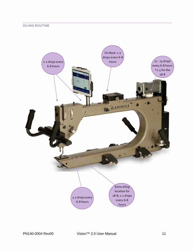
OILING ROUTINE
12 - 15 drops every 6-8 hours
*2-4 for the 18-8
1-2 drops every 6-8 hours
On Back: 1-2 drops every 6-8
hours
Extra oiling location for
18-8; 1-2 drops every 6-8
hours
1-2 drops every 6-8 hours
PN140-0004 Rev00 Vision™ 2.0 User Manual 11

OIL THE HOOK ASSEMBLY EACH TIME YOU CHANGE THE BOBBIN. PLACE THE OIL IN THE TOP OF THE THREE HOLES ALONG THE INSIDE OF THE HOOK ASSEMBLY. LET IT RUN DOWN INTO THE OTHER TWO HOLES. ROTATE THE HAND WHEEL THREE TURNS TO DISTRIBUTE THE OIL EVENLY.
PN140-0004 Rev00 Vision™ 2.0 User Manual 12

THREADING GUIDE
Step One Thread Lead Off Guide
Take the thread from the cone, up through the hole in the end of the Thread Lead Off guide and then through the middle hole from right to left.
1
2
5
3 4
6
12
7-10
11 13
14
15
PN140-0004 Rev00 Vision™ 2.0 User Manual 13

Step Two Small Guide
Take the thread through the back of the small thread guide, continuing toward the needle end of the machine.
Step Three & Four Intermittent Tension
Push a loop of thread through the Intermittent Tension thread guide. Open the loop and put it around the Intermittent Tension between the discs.
Step Five Thread Break Sensor Wheel
Wrap the thread counter clockwise around the Thread Break Sensor Wheel. A complete wrap is not required – the thread should engage approximately ½ of the circumference.
PN140-0004 Rev00 Vision™ 2.0 User Manual 14
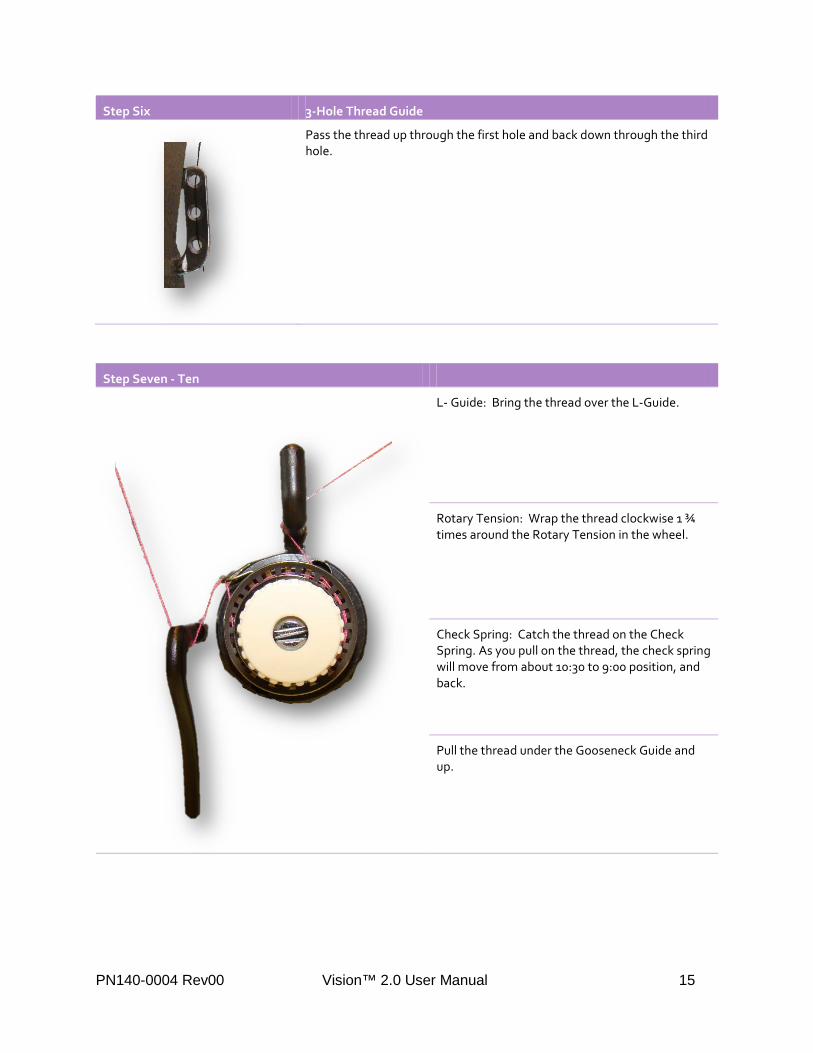
Step Six 3-Hole Thread Guide
Pass the thread up through the first hole and back down through the third hole.
Step Seven - Ten
L- Guide: Bring the thread over the L-Guide.
Rotary Tension: Wrap the thread clockwise 1 ¾ times around the Rotary Tension in the wheel.
Check Spring: Catch the thread on the Check Spring. As you pull on the thread, the check spring will move from about 10:30 to 9:00 position, and back.
Pull the thread under the Gooseneck Guide and up.
PN140-0004 Rev00 Vision™ 2.0 User Manual 15

Step Eleven Thread Guide
Only on 18-8 and 22-10: Snap the thread into the thread guide leading to the Take-up Lever.
Step Twelve Take-up Lever
Take the thread through the right side of the eye of the Take-up Lever toward the needle end of the machine.
PN140-0004 Rev00 Vision™ 2.0 User Manual 16

Step Thirteen Thread Guides
Snap the thread into the remaining thread guides leading to the needle.
Step Fourteen Needle
Pass the thread through the eye of the needle from the front to back and under the hopping foot.
PN140-0004 Rev00 Vision™ 2.0 User Manual 17

WHEN THE STITCHER IS RUNNING, THE INTERMITTENT TENSION ACTUALLY MOVES IN AND OUT ABOUT 1/32”. THIS ACTION IS INTENDED TO ADD TENSION AT JUST THE RIGHT TIME TO AID IN PULLING THE THREAD UP FROM THE BOTTOM OF THE QUILT. THIS ACTION MAKES IT HARDER TO PULL THREAD FROM THE THREAD SPOOL AND EASIER TO PULL THREAD FROM BELOW THE QUILT, PREVENTING LOOPS AND MAKES IT POSSIBLE TO QUILT WITH MOST QUILTING OR SPECIALTY THREAD. (THIS FEATURE IS NOT AVAILABLE ON THE 18-8)
TIP FOR EASY THREAD CHANGES – WHEN YOU NEED TO CHANGE THE THREAD, DON’T PULL THE CURRENT THREAD OUT AND RETHREAD USING THE NEW COLOR. INSTEAD, GO TO THE BACK OF THE MACHINE AND CUT THE THREAD EVEN WITH THE TOP OF THE CONE. REMOVE THE ORIGINAL CONE AND REPLACE IT WITH THE NEW COLOR. DRAW OFF SOME THREAD FROM THE NEW CONE, AND SECURELY TIE THE ENDS OF THE TWO COLORS TOGETHER. NOW, GO THE FRONT OF THE MACHINE, TAKE THE THREAD OUT OF THE NEEDLE, AND PULL ON THE THREAD UNTIL THE NEW COLOR IS IN PLACE. CUT OFF THE KNOT AND RETHREAD THE NEEDLE.
PN140-0004 Rev00 Vision™ 2.0 User Manual 18

USING THE ON-BOARD BOBBIN WINDER
Step One Thread Lead-Off
Take the thread from the cone, up through the hole in the end of the Thread Lead Off guide and then through the middle hole.
1
2-4 5 6
PN140-0004 Rev00 Vision™ 2.0 User Manual 19

Steps Two - Four Bobbin Winder Tension Thread Guide
Take the thread through the Pre-Bobbin Winder Tension Thread Guide.
Take the thread through the Post-Bobbin Winder Tension Thread Guide.
Pull the thread between the Pre-Bobbin Winder Tension Thread Guide and the Post-Bobbin Winder Tension Thread Guide slipping it between the metal tension discs of the Tensioner. The thread runs under the tensioner.
Step Five Thread Guide
Take the thread through the back of the small thread guide, continuing toward the needle end of the machine.
Step Six Bobbin
Wrap the thread several times around the bobbin clockwise and slip the thread through a hole facing you. Push the bobbin onto the bobbin spindle rotating until it clicks. Push the lever arm against the bobbin.
PN140-0004 Rev00 Vision™ 2.0 User Manual 20

This feature allows you to wind bobbins either while you are quilting, or not. The bobbin winder uses its own cone (or small cone) of thread, so if you have two cones of the same color, you can wind bobbins while you quilt. If you don’t have two cones of the same color, you can wind bobbins before you begin to quilt.
The bobbin should not be soft and mushy, but it also should not be so tight that you can’t feel a little give when pressing on the thread with your fingernail.
How to Wind Bobbins before Quilting:
• Load an empty bobbin as described above. • Be sure the bobbin case is not in the machine. • Remove the thread from the needle and take-up lever. Wrap it around the foam covering of one of the
handles to prevent tangling. • Choose Service & Maintenance from the Menu options, select Motor Operation. • Change the speed setting to about 30-50. • Check that the forward setting is selected (do not wind the bobbin in reverse). • Start by touching the start button. • When the bobbin is full, it will stop winding automatically. • Touch stop on the screen. • Remove the bobbin.
IT IS EASIER TO USE THE DIAGNOSTICS SCREEN – AND – YOU WON’T BE ADDING TO THE STITCH COUNTER LIKE YOU WOULD IF YOU WERE USING THE CONSTANT STITCH MODE.
IF WINDING WHILE QUILTING, WE ONLY RECOMMEND DOING SO WHILE USING CONSTANT MODE. THE VARIATIONS IN MOTOR SPEED IN THE OTHER MODES WILL RESULT IN POOR BOBBIN TENSION.
PN140-0004 Rev00 Vision™ 2.0 User Manual 21

THE BOBBIN CASE
Bobbin Threading Order Threading Instructions
Bobbin Case Insert the wound bobbin into the Bobbin Case with the thread unwinding clockwise.
Slot Slide the thread into the slot in the bobbin case.
Tension Spring & Thread Guide Slip the thread behind the Tension Spring and out the thread guide.
Latch Open the latch to secure the bobbin while inserting it into the hook assembly.
Hook Assembly Place the bobbin case into the hook assembly, release the latch and rotate to fit the hook latch tab into the notch in the hook.
Click it! Push the bobbin case into the hook assembly until it clicks.
THE BOBBIN CASE IS SIMILAR TO THOSE USED WITH DOMESTIC SEWING MACHINES, BUT LARGER (SIZE M), SO IT HOLDS MORE THREAD. EXACTLY HOW MUCH MORE DEPENDS ON THE THICKNESS OF THE THREAD.
Thread Guide
Tension Spring
Slot Tension Screw
Latch Hook Latch
Tab
PN140-0004 Rev00 Vision™ 2.0 User Manual 22

THE ANTI-BACKLASH SPRING IS A THIN METAL PIECE FOUND IN THE BOBBIN CASE. THIS PREVENTS THE BOBBIN THREAD FROM OVER-SPINNING WHEN THE MACHINE COMES TO A SUDDEN STOP. IT SHOULD BE REMOVED PERIODICALLY FOR CLEANING AS LINT WILL COLLECT BEHIND IT AND DEGRADE PERFORMANCE.
Inserting the Anti-backlash Spring:
• Insert the tabs of the anti-backlash spring into the slots on either side of the inside of the bobbin case.
• Use tweezers to place one of the tabs in one of the slots. Repeat for the other slot. Be careful not to bend or damage the spring as you insert it.
PN140-0004 Rev00 Vision™ 2.0 User Manual 23

INSERTING THE BOBBIN CASE
To Insert the Bobbin Case into the Machine:
• Use the spring loaded handle to hold the bobbin in the case when inserting or removing the bobbin. • Place the bobbin case into the hook assembly so the handle points in a 4:00 direction. • Release the handle once the bobbin case is being inserted into the hook assembly so you can hear it click
when it is inserted fully. This guarantees you will not damage the machine by running it with the bobbin case partially inserted.
• Push the bobbin in fully so it clicks.
PN140-0004 Rev00 Vision™ 2.0 User Manual 24

SETTING THE TENSION
SETTING THE INTERMITTENT TENSION
Intermittent tension adjustments might be needed on every quilt combination you do because the thread, fabric, batting and backing all affect the stitch quality.
To set the Intermittent Tension:
• Start with the Intermittent Tension set at the baseline by turning the knob until it is flush with the inside threaded shaft.
• Turn the knob a half turn to the right (clockwise) to tighten and the left (counter clockwise) to loosen. When adjusting the tension, always turn the intermittent tension knob at least half a turn at a time. It is a coarse adjustment and less than a half of a turn will not appreciably change the tension.
IF THE TENSION IS TOO TIGHT OR TOO LOOSE, THE THREAD WILL QUICKLY WORK ITS WAY OUT OF THE DISKS. BE SURE THE THREAD STAYS NESTLED BETWEEN THE TWO TENSION DISKS. IF IT SLIPS OUT, THE QUILT WILL HAVE POOR TENSION.
PN140-0004 Rev00 Vision™ 2.0 User Manual 25

SETTING THE ROTARY TENSION
The Rotary Tension prepares and holds the thread for the check spring and should remain loose, just tight enough so the wheel rotates when stitching. This also serves as a fine adjuster to dial tension in exactly where you need it.
To set the Rotary Tension:
• Start with the Rotary Tension set at the baseline by turning the knob until it is flush with the inside threaded shaft.
• Turn the knob to the right (clockwise) to tighten and to the left (counter clockwise) to loosen.
PN140-0004 Rev00 Vision™ 2.0 User Manual 26
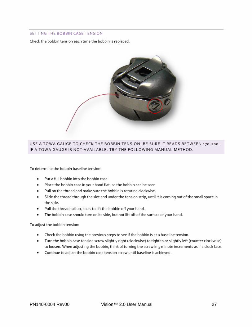
SETTING THE BOBBIN CASE TENSION
Check the bobbin tension each time the bobbin is replaced.
USE A TOWA GAUGE TO CHECK THE BOBBIN TENSION. BE SURE IT READS BETWEEN 170-200. IF A TOWA GAUGE IS NOT AVAILABLE, TRY THE FOLLOWING MANUAL METHOD.
To determine the bobbin baseline tension:
• Put a full bobbin into the bobbin case. • Place the bobbin case in your hand flat, so the bobbin can be seen. • Pull on the thread and make sure the bobbin is rotating clockwise. • Slide the thread through the slot and under the tension strip, until it is coming out of the small space in
the side. • Pull the thread tail up, so as to lift the bobbin off your hand. • The bobbin case should turn on its side, but not lift off of the surface of your hand.
To adjust the bobbin tension:
• Check the bobbin using the previous steps to see if the bobbin is at a baseline tension. • Turn the bobbin case tension screw slightly right (clockwise) to tighten or slightly left (counter clockwise)
to loosen. When adjusting the bobbin, think of turning the screw in 5 minute increments as if a clock face. • Continue to adjust the bobbin case tension screw until baseline is achieved.
PN140-0004 Rev00 Vision™ 2.0 User Manual 27
CHECKING THE TOP THREAD TENSION
• Start with a properly tensioned bobbin case. • Attach a test piece. • Pull up the bobbin, tie-off and stitch at a normal speed. Include some soft curves, tight spirals, straight
lines (horizontal and vertical) and sharp points. Look closely at the stitch quality. • Remove the pins and check the underneath too.
Changing the Top Thread Tension
• If the tension is poor on the back of the quilt - top thread loops, bobbin thread lying flat, eyelashes or stitches not embedding in the fabric - then tighten intermittent tension ½ turn at a time to "pull" the stitch (the bobbin and top thread connection) into the middle of the quilt.
• If tension is poor on top then check the bobbin case first. If it seems OK, loosen the intermittent tension ½ turn at a time until stitch balance is achieved.
PN140-0004 Rev00 Vision™ 2.0 User Manual 28

PULLING UP THE THREAD
To begin stitching, the bobbin thread needs to be brought to the topside of the quilt.
To bring up the Bobbin Thread:
• Thread the needle. • Hold the thread tail securely. • Take a single stitch. • Holding the tail thread in both hands, sweep the thread tail under the hopping foot. The bobbin thread
will come up. • Grasp both thread tails securely or wrap them around a straight pin out of the way of your stitching. • Begin stitching. • Trim the tails or leave to bury later.
ENDING THE THREAD
To end stitching, the bobbin thread needs to be brought to the topside of the quilt again.
• End stitching with a tie off or locking stitches. • Pull the machine head away from the stitching area and catch the extra thread in your hand. • While holding the thread, bring the head back to the last stitch. • Take a single stitch. • Pull the machine head away from the stitching area again. • Secure both threads in your hand. • Trim close to the quilt.
TO BURY THE THREAD, LEAVE BOTH TAILS FROM THE FRONT AND BACK ON THE TOP OF THE QUILT AT LEAST 6-8” LONG. THREAD THEM, ONE AT A TIME, ON A HAND NEEDLE AND TAKE A LONG STITCH THROUGH THE TOP AND BATTING, BUT NOT THROUGH THE BACKING. PULL UP THE THREAD UNTIL TAUNT. TRIM AT THE SURFACE OF THE QUILT. THE THREAD WILL BOUNCE BACK INTO THE QUILT AND HIDE.
BURYING THREADS ALONG STITCHING LINES WILL HELP HIDE THEM.
PN140-0004 Rev00 Vision™ 2.0 User Manual 29

LOADING THE QUILT
To load a quilt onto a black GS1 Table:
1. Use the latches as needed to secure or free the rollers.
2. Release the Pivotal Access by removing the pin. Let it rest in the straight position.
PN140-0004 Rev00 Vision™ 2.0 User Manual 30

3. Pin the quilt top to the leader labeled Top, right side up.
4. Roll the quilt top onto the Top roller. 5. Pull the backing leader up, around and over the belly bar only. 6. Secure the backing leader with the end clamps to hold the leader in place for pinning. 7. Pin the backing to the leader labeled Backing, wrong side up. 8. Unclamp the backing leader. 9. Lay the backing over the Pickup roller.
Belly Bar – no leader
Pivotal Access Bar – no leader
Top Bar – with leader
Backing Bar – with leader
Belly Bar – no leader
Pickup Roller – with leader
PN140-0004 Rev00 Vision™ 2.0 User Manual 31

10. Roll the backing onto the Backing roller until the edge is even with the pickup leader. 11. Pin the backing to the pickup leader labeled Pickup. 12. Roll the backing onto the Backing roller until the Pickup leader edge is comfortably reachable from the
front of the table. 13. Pull up the quilt top to meet the Pickup leader edge. Secure the latch and let the quilt top drop down the
front of the table. 14. Lay the batting on the backing, matching edges along the Pickup leader edge. 15. Baste a line at the top of the batting using the horizontal channel lock. 16. Tuck the batting down through the Pivotal bar and the Top roller. 17. Pull the top up to match the line made on the batting to square the quilt and secure with a few pins. 18. Baste the quilt top along the top edge.
To load a quilt onto a white Home Pro Table:
1. Pin the backing to the leader labeled Backing, wrong side up. 2. Roll the backing onto the Backing roller. 3. Pin the quilt top to the leader labeled Top, right side up. 4. Roll the quilt top onto the Top roller. 5. Pin the backing to the Pickup leader. 6. Lay the batting on the backing, matching edges along the Pickup leader edge. 7. Baste a line at the top of the batting using the horizontal channel lock. 8. Tuck the batting down between the Backing roller and the Top roller. 9. Pull the top up to match the line made on the batting to square the quilt and secure with a few pins. 10. Baste the quilt top along the top edge.
PICKUP BACKING
TOP
PN140-0004 Rev00 Vision™ 2.0 User Manual 32

ADJUSTING THE TABLES
When quilting, the quilt is rolled onto the Pickup roller causing the diameter of the roll to increase as more of the quilt is completed. It is important to adjust the Pickup roller to clear the head for smooth quilting. Not raising the pickup roller will create drag while quilting.
To adjust the Pickup Roller on the black GS1 Table:
1. Turn the handle at the right end of the Pick-Up Roller to raise or lower (clockwise to raise, counter clockwise to lower).
2. Raise the roller so the roller clears the throat of the machine by ½”. 3. Check the height of the Pick-Up Roller before you roll and after.
To adjust the Pickup Roller on the white Home Pro Table:
PN140-0004 Rev00 Vision™ 2.0 User Manual 33

1. Manually adjust the height of the Pick-Up Roller at each end of the table by loosening the black knob, moving the bar up or down and retightening. This must be done on both ends of the table.
2. Measure the height at each end with the Pickup Roller Guide to be sure the roller is level. 3. Raise the roller so the roller clears the throat of the machine by ½”. 4. Check the height of the Pick-Up Roller before you roll and after.
PN140-0004 Rev00 Vision™ 2.0 User Manual 34

THE TABLET
SEE THE SAMSUNG TAB 3 QUICK START GUIDE FOUND IN THE TABLET BOX FOR BASIC TABLET INFORMATION.
Find the Vision™ 2.0 Application Icon on the tablet Home Screen and tap to launch it. It can also be found on the app screen.
Samsung Tablet Updates:
SAMSUNG WILL REGULARLY PUSH UPDATES FOR THE TABLET. WE RECOMMEND THAT YOU DO NOT INSTALL THESE UPDATES UNTIL WE PUT A NOTICE ON THE GAMMILL WEBSITE RECOMMENDING YOU DO SO. THIS WILL GIVE US TIME TO CHECK THE UPDATE TO SEE HOW IT WILL INTERACT WITH OUR APPLICATION AND YOUR VISION™ 2.0 SYSTEM.
PN140-0004 Rev00 Vision™ 2.0 User Manual 35

THE VISION™ 2.0 APPLICATION
The main screen offers the most commonly used features at a finger’s touch. Notice this screen is broken down into four sections: the title bar, top ribbon, mode section and the bottom ribbon.
The Title Bar contains the application title, key quilting features used for specialty functions. The Top Ribbon provides access to the menu, quilting modes and My Stitch™ presets. In the Mode Section, the active stitching mode is displayed along with access to stitching adjustments such as speed and stitches per inch along with related features such as starting and stopping stitching. The Bottom Ribbon accesses the My Stitch™ Buttons features.
Top Ribbon
Mode Section
Bottom Ribbon
Title Bar
PN140-0004 Rev00 Vision™ 2.0 User Manual 36
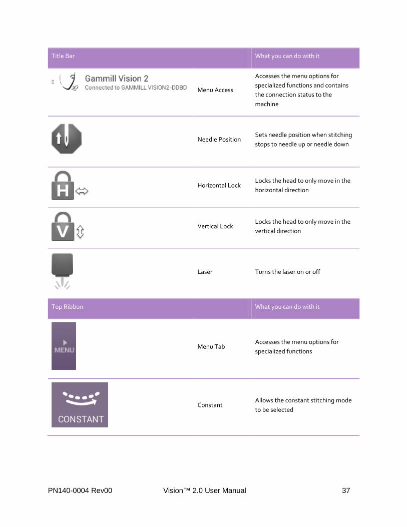
Title Bar What you can do with it
Menu Access
Accesses the menu options for specialized functions and contains the connection status to the machine
Needle Position Sets needle position when stitching stops to needle up or needle down
Horizontal Lock Locks the head to only move in the horizontal direction
Vertical Lock Locks the head to only move in the vertical direction
Laser Turns the laser on or off
Top Ribbon What you can do with it
Menu Tab Accesses the menu options for specialized functions
Constant Allows the constant stitching mode to be selected
PN140-0004 Rev00 Vision™ 2.0 User Manual 37

Regulate Allows the regulate stitching mode to be selected
Coast Regulate Allows the coast regulate stitching mode to be selected
Baste Allows the basting mode to be selected
My Stitch™ Presets 1 & 2
Allows two modes and settings to be saved for easy access and for use by the My Stitch™ buttons.
Mode Section What you can do with it
Stitching Mode Indicates the active stitching mode.
Stitch Setting Indicates the stitch setting and allows stitch adjustment
Stitch Timer Tracks stitching time and is resettable
PN140-0004 Rev00 Vision™ 2.0 User Manual 38

Stitch Counter Tracks the stitch count and is resettable
Bobbin Gauge Tracks the bobbin usage and alarms when the bobbin is low
Tie Off Function Initiates a series of tiny locking stitches
Start Button Starts stitching
Stop Button Stops stitching
Bottom Ribbon What you can do with it
My Stitch™ Buttons A-D
Assigns functions to each of the four handle buttons.
IF THE TOUCH SCREEN SEEMS LESS SENSITIVE AFTER A WHILE, REBOOT THE TABLET BY PRESSING AND HOLDING THE TABLET POWER BUTTON. SELECT RESTART FROM THE WINDOW. ONCE RESTARTED, REOPEN THE APP BY TOUCHING THE ICON.
WHEN TURNING OFF THE MACHINE, PUT THE TABLET TO SLEEP BY PRESSING THE BUTTON ON THE TOP LEFT EDGE OF THE TABLET. IF THE TABLET IS LEFT ON WITH THE MACHINE OFF, THE TABLET BATTERY WILL BE DEPLETED QUICKLY.
PN140-0004 Rev00 Vision™ 2.0 User Manual 39

STITCHING
:
! CAUTION
Moving needle can cause injury. Keep body parts and loose clothing away.
To begin and end stitching, there are several options available.
Start and Stop On-screen Buttons:
• Select the green START button located in the bottom right mode portion of the screen to enable stitching using the main screen. To stop, select the red STOP button located in the same area.
Handle Button:
• Use the My Stitch™ feature to program any handle button to control stitch starting and stopping to match your needs. The Start/Stop Stitching control can be assigned to any of the four buttons, but one must be set to Start/ Stop Stitching.
• Press the handle button assigned to start or stop stitching to engage and disengage stitching.
SIDE NOTE: THE MACHINE WILL STOP STITCHING ON ITS OWN IF IT SENSES NO MOVEMENT FOR 10 SECONDS. THIS IS A SAFETY FEATURE THAT CANNOT BE DISABLED.
PN140-0004 Rev00 Vision™ 2.0 User Manual 40

STITCHING MODES
Vision™ 2.0 features four stitching modes: constant, regulate, coast regulate and baste. Stitching modes are selected in the top ribbon and the active mode is displayed in the mode section and highlighted on the top ribbon.
CONSTANT MODE:
Constant Mode stitches at an unchanging speed. The rate the needle moves up and down to stitch does not increase or decrease with the movement of the head, but rather stays constant.
To engage Constant Mode:
• Tap the Constant icon in the top ribbon. • Notice the stitching mode is indicated in the mode section in the middle of the screen.
To set Constant Mode speed:
• Adjust the speed up or down by tapping the plus or minus sign in the mode section. • Speed can be set from 0 to 100.
To adjust Constant Mode speed while quilting:
• Tap the plus or minus sign to increase or decrease speed while stitching, or • Set the My Stitch™ Buttons to adjust setting up and/or adjust setting down. Then use the handle buttons
to adjust speed while stitching.
PN140-0004 Rev00 Vision™ 2.0 User Manual 41

REGULATE MODE:
Regulate Mode controls the length of the stitch regardless of the movement of the machine. Whether the head moves slowly or quickly, the stitch length remains the same.
To engage Regulate Mode:
• Tap the Regulate icon in the top ribbon. • Notice the stitching mode is indicated in the mode section in the middle of the screen.
To set Regulate Mode:
• Adjust the stitch length up or down by tapping the plus or minus sign in the mode section. • Stitch length can be set from 8 to 24 stitches per inch.
To adjust Regulate Mode while quilting:
• Tap the plus or minus sign to increase or decrease the stitch length while stitching, or • Set the My Stitch™ Buttons to adjust setting up and/or adjust setting down. Then use the handle buttons
to adjust speed while stitching.
BECAUSE THE MACHINE IS MAINTAINING A SET NUMBER OF STITCHES PER INCH, WHEN THE HEAD STOPS MOVING, STITCHING PAUSES. MOVING THE HEAD WILL CAUSE IT TO RESUME STITCHING. IF THE HEAD IS NOT MOVED FOR 10 SECONDS, THE MACHINE WILL STOP STITCHING. PRESS THE START BUTTON TO RESUME STITCHING.
PN140-0004 Rev00 Vision™ 2.0 User Manual 42

Over Speed Alarm:
WHEN THE STITCHES PER INCH ARE SET AT A HIGH NUMBER, AND THE HEAD IS MOVED QUICKLY, IT IS POSSIBLE THAT THE REQUIRED MOTOR SPEED WOULD BE HIGHER THAN CAN BE MAINTAINED FOR AN EVEN STITCH. IF THIS SITUATION OCCURS, AN ALERT MESSAGE: OVER SPEED WILL APPEAR ON THE SCREEN. IF THIS APPEARS, LONG STITCHES COULD RESULT. SETTING A LONGER LENGTH OF STITCH, SLOWING MOVEMENTS, OR BOTH WILL PREVENT THIS. IF THE MESSAGE CONTINUES TO OCCUR, FURTHER TROUBLESHOOTING INSTRUCTIONS ARE AVAILABLE IN THE VISION 2.0 SERVICE MANUAL.
PN140-0004 Rev00 Vision™ 2.0 User Manual 43

COAST REGULATE MODE:
Coast Regulate Mode offers graceful transitions between large sweeping patterns and fill work. By fluctuating between stitch regulation and constant speed, the machine adjusts to the rate the head is moved providing the best of both worlds.
To engage Coast Regulate Mode:
• Touch the Coast Regulate icon in the top ribbon. • Notice the stitching mode is indicated in the mode section in the middle of the screen.
To set Coast Regulate Mode:
• Touch the plus or minus sign under Stitches per Inch to adjust stitch length. • Touch the plus or minus sign under Speed to adjust the stitching speed.
To adjust Coast Regulate Mode while quilting:
• Touch the plus or minus sign to increase or decrease speed while stitching or stitches per inch, or • Set the My Stitch™ Buttons to adjust setting up and/or adjust setting down. Then use the handle buttons
to adjust speed while stitching.
COAST REGULATE MODE FLUCTUATES AUTOMATICALLY BETWEEN CONSTANT AND REGULATED MODES. THE SET SPEED AND STITCHES PER INCH ARE USED TO DECIDE WHICH MODE THE MACHINE WILL STITCH IN. AS THE HEAD IS MOVED, THE MACHINE CONTINUALLY LOOKS AT THE MOTOR SPEED REQUIRED TO MAINTAIN THE STITCHES PER INCH. IF THIS RATE
PN140-0004 Rev00 Vision™ 2.0 User Manual 44

OF MOVEMENT IS ABOVE THE SET SPEED, THE MACHINE OPERATES IN A REGULATED MODE AND MAINTAINS THE SET STITCHES PER INCH. IF THE SPEED IS BELOW THE SET SPEED, THEN THE MACHINE RUNS AT A CONSTANT MODE AT THE SPEED SETTING.
AS AN ADVANCED FEATURE, THE POINT AT WHICH THE MACHINE SWITCHES FROM REGULATE TO CONSTANT CAN BE SELECTED INDEPENDENTLY FROM THE CONSTANT SPEED.
To enable the Coast Regulate Switch Point:
• Touch the Change Switch Point (advanced) button located below the words “Coast Regulate” in the Stitching Mode indicator in the white mode section.
• The switch point appears in the mode section.
To set the Coast Regulate Switch Point:
• Touch the plus or minus sign below the Switch Point indicator to adjust up or down.
To disable the Coast Regulate Switch Point:
• Touch the Link Switch Point to Speed (default) button located below the words “Coast Regulate” in the Stitching Mode indicator in the mode section.
PN140-0004 Rev00 Vision™ 2.0 User Manual 45

BASTE MODE:
Baste mode functions like stitch regulation on a large scale, stitching from ¼ inch up to 4 inches per stitch. This helps to stabilize the quilt.
To engage Baste Mode:
• Touch the Baste icon in the top ribbon. • Notice the stitching mode is indicated in the mode section in the middle of the screen.
To set Baste Mode:
• Touch the plus or minus sign to adjust the stitch length. • Basting length can be set from ¼ inch to 4 inches in ¼ inch increments.
To adjust Baste Mode while basting:
• Touch the plus or minus sign to increase or decrease stitch length while stitching, or • Set the My Stitch™ Buttons to adjust setting up and/or adjust setting down. Then use the handle buttons
to adjust speed while stitching.
BECAUSE THE MACHINE IS MAINTAINING A SET NUMBER OF STITCHES PER INCH, WHEN THE HEAD STOPS MOVING, STITCHING PAUSES. MOVING THE HEAD WILL CAUSE IT TO RESUME STITCHING. IF THE HEAD IS NOT MOVED FOR 10 SECONDS, THE MACHINE WILL STOP STITCHING. PRESS THE START BUTTON TO RESUME STITCHING.
PN140-0004 Rev00 Vision™ 2.0 User Manual 46

Over Speed Alarm:
WHEN THE STITCH LENGTH IS SET AT A LOWER NUMBER, AND THE HEAD IS MOVED QUICKLY, IT IS POSSIBLE THAT THE MACHINE CAN BE MOVED FASTER THAN THE STITCHING CAN MAINTAIN. IF THIS SITUATION OCCURS, AN ALERT MESSAGE: OVER SPEED WILL APPEAR ON THE SCREEN. IF THIS APPEARS, LONG STITCHES COULD RESULT. SETTING A LONGER LENGTH OF STITCH, SLOWING MOVEMENTS, OR BOTH WILL PREVENT THIS. IF THE MESSAGE CONTINUES TO OCCUR, FURTHER TROUBLESHOOTING INSTRUCTIONS ARE AVAILABLE IN THE VISION 2.0 SERVICE MANUAL.
PN140-0004 Rev00 Vision™ 2.0 User Manual 47

MY STITCH™ PRESETS
My Stitch™ Presets offers a way to create presets for modes and settings. This is very useful for commonly used values. Additionally, by using the My Stitch™ Select Button, the user may change between the two presets without stopping stitching.
To access a My Stitch™ Preset:
• Tap the numbered My Stitch™ Preset button desired to access. • Notice the stitching mode is indicated in the mode section in the middle of the screen and the active My
Stitch™ Preset button is white.
To set a My Stitch™ Preset:
• Once the mode and settings are adjusted, touch and hold the desired preset button for 2 seconds to program it.
• Notice the mode and setting are indicated below the My Stitch™ Preset button.
To use the My Stitch™ Presets with My Stitch™ Buttons:
• Set one of the My Stitch™ Buttons to My Stitch Select. • While stitching, press the handle button set to My Stitch Select. • Notice the stitching mode instantly changes to the newly selected preset while stitching.
PN140-0004 Rev00 Vision™ 2.0 User Manual 48

EACH OF THE TWO PRESETS CAN BE SET TO ANY MODE AND SETTING COMBINATION THAT IS AVAILABLE TO THE USER. WHILE THE EXAMPLE IMAGE SHOWS TWO DIFFERENT MODES, IT IS POSSIBLE TO SET BOTH PRESETS TO THE SAME MODE WITH DIFFERENT SETTINGS, ETC. THIS FEATURE IS LIMITED ONLY BY THE USER’S IMAGINATION.
To access Help:
• Press the small gear above the My Stitch Preset buttons.
PN140-0004 Rev00 Vision™ 2.0 User Manual 49

MY STITCH™ BUTTONS
The My Stitch™ Buttons feature offers adjustment while stitching, fingertip access to key features and assistance with common functions. Each of the four My Stitch™ Buttons can be customized and set to change functions and speeds on the fly as well as access key functions such as tie off.
Each of the four buttons can be configured to any one of the following functions:
Function Function Description
Adjust Setting Down When pressed, the setting of the current mode will be decreased by one increment. If in Coast Regulate mode, only the Speed setting will be decreased.
Adjust Setting Up When pressed, the setting of the current mode will be increased by one increment. If in Coast Regulate mode, only the Speed setting will be increased.
Needle Position If the needle is up, when pressed, the needle will move to the down position and vice versa. When pressed again, the needle will move back to the up position.
Single Stitch When pressed, the machine will take one stitch.
Start / Stop Stitching This starts or stops the machine from stitching. One button must be set to this setting for the machine to function.
Tie Off When pressed, the machine will begin the tie-off function.
My Stitch Select When pressed, the machine function will switch between the two My Stitch™ Presets. If stitching, the machine will not stop, but will instantly switch between the two modes.
PN140-0004 Rev00 Vision™ 2.0 User Manual 50

EACH BUTTON PERFORMS THE SAME FUNCTION WHETHER STITCHING IS STARTED OR STOPPED. HOWEVER, SOME FUNCTIONS SUCH AS NEEDLE POSITION AND SINGLE STICH ARE DISABLED ONCE STITCHING IS STARTED.
LOCKING THE BUTTON ASSIGNMENTS PREVENTS THEM FROM EASILY BEING CHANGED.
Locking the My Stitch Buttons:
• Touch the small gear beside the My Stitch™ Buttons.
• Touch the box to select the option to lock the button assignments.
PN140-0004 Rev00 Vision™ 2.0 User Manual 51

AUTOMATIC TIE-OFF FUNCTION
Secure stitching with the Automatic Tie-Off function that delivers a set number of stitches at a preselected density.
To access the Automatic Tie-Off:
• Touch the tied bow icon to access the tie-off mode.
PN140-0004 Rev00 Vision™ 2.0 User Manual 52

• Notice the stitching mode changes to Automatic Tie-Off in the mode section in the middle of the screen and the tied bow indicates the number of stitches left in the tie-off.
To set the Automatic Tie-Off:
• Touch the plus or minus sign below “Stitches per Inch” to adjust the stitch length. The Stitches per Inch may be adjusted from 12 to 60.
• Touch the plus or minus sign below “Number of Stitches” to adjust the number of stitches used in the tie-off. The Number of Stitches may be adjusted from 2 to 15.
PN140-0004 Rev00 Vision™ 2.0 User Manual 53

To reset the defaults for the Automatic Tie-Off:
• Touch the Reset to Defaults button located under the Automatic Tie-Off label in the center of the screen.
• Notice the Stitches per Inch and Number of Stitches settings return to their original settings.
To cancel the Automatic Tie-Off:
• Touch the Cancel button located under the Automatic Tie-Off label in the center of the screen. • Or touch the tied bow icon again to cancel. • Notice the screen changes back to the mode and settings selected prior to entering the Automatic Tie-
Off function.
PN140-0004 Rev00 Vision™ 2.0 User Manual 54

To execute an Automatic Tie-Off:
• Touch the Start button on the screen.
• Or press the handle button set to start/ stop stitching. • Move the head. • Notice the machine begins stitching as soon as the head moves. The number beside the tied bow also
counts down as the stitches are delivered.
PN140-0004 Rev00 Vision™ 2.0 User Manual 55

IF THE RED STOP BUTTON IS PRESSED DURING A TIE-OFF, THE CURRENT TIE-OFF WILL STOP BUT WILL NOT LEAVE THE TIE-OFF MODE. IF THE GREEN START BUTTON IS PUSHED AGAIN, THE TIE-OFF WILL START OVER RATHER THAN PICKING UP WHERE STOPPED.
WHEN THE AUTOMATIC TIE-OFF FUNCTION IS COMPLETE, THE SCREEN WILL CHANGE TO SHOW IT IS COMPLETE BRIEFLY AND THEN CHANGE BACK TO THE MODE AND SETTINGS SELECTED PRIOR TO ENTERING THE AUTOMATIC TIE-OFF FUNCTION.
PN140-0004 Rev00 Vision™ 2.0 User Manual 56

STITCH TIMER FUNCTION
The Stitch Timer function continually monitors the amount of time spent stitching making it easy to keep track of the time spent on a project.
To reset the Stitch Timer:
• Touch the Stitch Timer icon. • Notice a window appears asking if you are sure you want to reset the Stitch Timer.
PN140-0004 Rev00 Vision™ 2.0 User Manual 57

• Touch the Reset the Timer button to reset the time. • Notice the timer display resets to 00:00.
To cancel resetting the Stitch Timer:
• Touch the Cancel button on the Stitch Timer window. • Notice the window closes.
TIME IS DISPLAYED IN AN HH:MM:SS FORMAT WHERE HH IS THE NUMBER OF HOURS, MM IS THE NUMBER OF MINUTES, AND SS IS THE NUMBER OF SECONDS. IF THE TIMER EXCEEDS 99:59:59, THE TIMER WILL AUTOMATICALLY RESET TO 00:00.
PN140-0004 Rev00 Vision™ 2.0 User Manual 58

STITCH COUNTER FUNCTION
The Stitch Counter continually counts the number of stitches taken making it easy to track the number of stitches in a project.
To reset the Stitch Counter:
• Touch the Stitch Counter icon. • Notice a window appears asking if you are sure you want to reset the Stitch Counter.
PN140-0004 Rev00 Vision™ 2.0 User Manual 59

• Tap the Reset the Counter button to reset the count. • Notice the count display resets to 0.
To cancel resetting the Stitch Counter:
• Tap the Cancel button on the Stitch Counter window. • Notice the window closes.
THIS INDICATOR DISPLAYS THE NUMBER OF STITCHES TAKEN, WITH A MAXIMUM OF 999,999 ALLOWED. AT THIS POINT, THE INDICATOR WILL AUTOMATICALLY RESET TO 0.
PN140-0004 Rev00 Vision™ 2.0 User Manual 60

BOBBIN GAUGE FUNCTION
The Bobbin Gauge function monitors the amount of top thread used to estimate usage of the bobbin thread displaying a percentage of the amount of the bobbin thread remaining.
To use the Bobbin Gauge:
• Tap the Bobbin Gauge icon. • Notice the Bobbin Gauge settings window appears.
PN140-0004 Rev00 Vision™ 2.0 User Manual 61

• Tap the box beside the “Use the Bobbin Gauge” message. • Notice a check mark appears indicating the Bobbin Gauge is active.
To set the Thread Factor:
• Touch the plus or minus sign to adjust the Thread Factor up or down. The Thread Factor may be adjusted from 1 to 10.
• Set the Thread Factor higher for thinner threads. • Set the Thread Factor lower for thicker threads. • Tap the OK button.
THE THREAD FACTOR IS A VALUE HELPS DETERMINE THE BOBBIN THREAD USAGE. THE BEST WAY TO THINK OF THE FACTOR IS TO RELATE IT TO THE THICKNESS OF THE BOBBIN THREAD. THE THICKER THE BOBBIN THREAD, THE LESS THREAD WILL FIT ON A BOBBIN. USE A LOWER NUMBER WHEN USING THICKER THREAD. ADJUST THE BOBBIN FACTOR AND OBSERVE WHEN THE ALARM OCCURS VERSUS THE ACTUAL AMOUNT OF THREAD LEFT ON YOUR BOBBINS. MAKE ADJUSTMENTS BASED ON THIS FEEDBACK UNTIL YOU OBTAIN THE DESIRED RESULTS.
To reset the Bobbin Gauge:
• Tap the Reset the Gauge button. • Notice the Bobbin Gauge on the main screen is reset to 100%
To disable the Bobbin Gauge:
• Tap the checked box beside the “Use the Bobbin Gauge” message. • Notice the check mark disappears indicating the Bobbin Gauge is now inactive.
PN140-0004 Rev00 Vision™ 2.0 User Manual 62

• Touch the OK button.
• Notice the window closes and the Bobbin Gauge icon is greyed out on the main screen and no percentage is shown.
When the Bobbin Gauge is active, as you stitch, the Bobbin Gauge percentage will decrease. When the percentage reaches 10%, the system will issue an alert to warn you that the bobbin is almost empty.
PN140-0004 Rev00 Vision™ 2.0 User Manual 63

SINCE IT IS NOT POSSIBLE TO DIRECTLY MEASURE THE AMOUNT OF BOBBIN THREAD REMAINING, THE SYSTEM MUST USE THE USAGE OF THE TOP THREAD TO GAUGE THE USE OF THE BOBBIN THREAD. THE SYSTEM ASSUMES SOME THINGS SUCH AS TENSION, BOBBIN CAPACITY, AND HOW FULL THE BOBBIN IS FILLED TO, BUT PROPER ESTIMATION OF THE REMAINING BOBBIN THREAD STILL RELIES ON INPUT FROM THE OPERATOR.
THE BOBBIN GAUGE MAY BE USED, BUT ONLY THE ALERT DISABLED. SEE THE SECTION ON THE ALERT SCREEN FOR ADDITIONAL INFORMATION ON THIS CAPABILITY.
PN140-0004 Rev00 Vision™ 2.0 User Manual 64

CONNECTION INFORMATION
The Vision™ 2.0 Application communicates to the quilting system using Bluetooth. When connected, the text will read “Connected to Gammill Vision2-XXXX” where XXXX is the last 4 digits of the address of the system it is connected to.
IF THE APPLICATION IS NOT CONNECTED TO A SYSTEM, IT WILL READ “DISCONNECTED”. IF THIS IS THE CASE, COMMUNICATION NEEDS TO BE ESTABLISHED. SEE THE SECTION ON BLUETOOTH CONNECTION FOR ADDITIONAL INFORMATION ON HOW TO CONNECT THE TABLET TO THE SYSTEM.
PN140-0004 Rev00 Vision™ 2.0 User Manual 65

NEEDLE STOP POSITION
The top bar in the user interface contains several icons allowing quick and easy use of the machine. The first of these icons controls the needle position when stitching stops.
To stop stitching with the needle down:
• Tap the Needle Stop Position icon so the needle indicates the down position. • Notice, when stitching stops, the needle stops in the down position.
To stop stitching with the needle up:
• Tap the Needle Stop Position icon so the needle indicates the up position. • Notice, when stitching stops, the needle stops in the up position.
WHEN USING THE NEEDLE DOWN POSITION, USE OF A SINGLE STITCH WILL RESULT IN THE NEEDLE STOPPING IN THE UP POSITION FOR THE FIRST PRESS. SUBSEQUENT PRESSES OF THE SINGLE STITCH BUTTON WILL RESULT IN FULL STITCHES TAKEN.
PN140-0004 Rev00 Vision™ 2.0 User Manual 66

HORIZONTAL CHANNEL LOCK
The Horizontal Channel Lock Icon limits the motion of the machine to a horizontal direction, not allowing any vertical movement. This feature aids in creating perfectly straight lines whether for basting or stitching.
To engage the Horizontal Channel Lock:
• Tap the open Horizontal Channel Lock icon. • Notice the icon locks indicating the channel lock is engaged and the machine only moves in a horizontal
direction left or right, but cannot move up or down vertically.
To disengage the Horizontal Channel Lock:
• Tap the closed Horizontal Channel Lock icon. • Notice the icon unlocks indicating the channel lock is disengaged and the machine moves freely in all
directions.
PN140-0004 Rev00 Vision™ 2.0 User Manual 67
VERTICAL CHANNEL LOCK
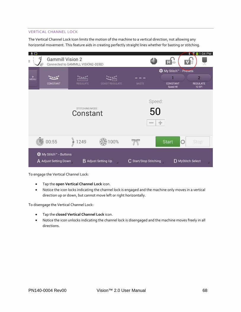
The Vertical Channel Lock Icon limits the motion of the machine to a vertical direction, not allowing any horizontal movement. This feature aids in creating perfectly straight lines whether for basting or stitching.
To engage the Vertical Channel Lock:
• Tap the open Vertical Channel Lock icon. • Notice the icon locks indicating the channel lock is engaged and the machine only moves in a vertical
direction up or down, but cannot move left or right horizontally.
To disengage the Vertical Channel Lock:
• Tap the closed Vertical Channel Lock icon. • Notice the icon unlocks indicating the channel lock is disengaged and the machine moves freely in all
directions.
PN140-0004 Rev00 Vision™ 2.0 User Manual 68

LASER
The Laser icon turns the laser on or off with the tap of a finger.
C ! CAUTION Laser Radiation. Avoid direct exposure to beam.
To turn the laser on:
• Touch the greyed Laser icon. • Notice the laser on the Laser icon turns red indicating that the laser is on.
To turn the laser off:
• Touch the red Laser icon. • Notice the laser on the Laser icon turns grey indicating that the laser is off.
PN140-0004 Rev00 Vision™ 2.0 User Manual 69

THIS FUNCTION CONTROLS THE LASER, WHETHER PLUGGED IN TO THE FRONT OR REAR OF THE MACHINE. THE INTENSITY (SPOT SIZE) OF THE LASER IS ALSO USER ADJUSTABLE, AND IS EXPLAINED IN THE LASER SETTINGS SECTION.
PN140-0004 Rev00 Vision™ 2.0 User Manual 70
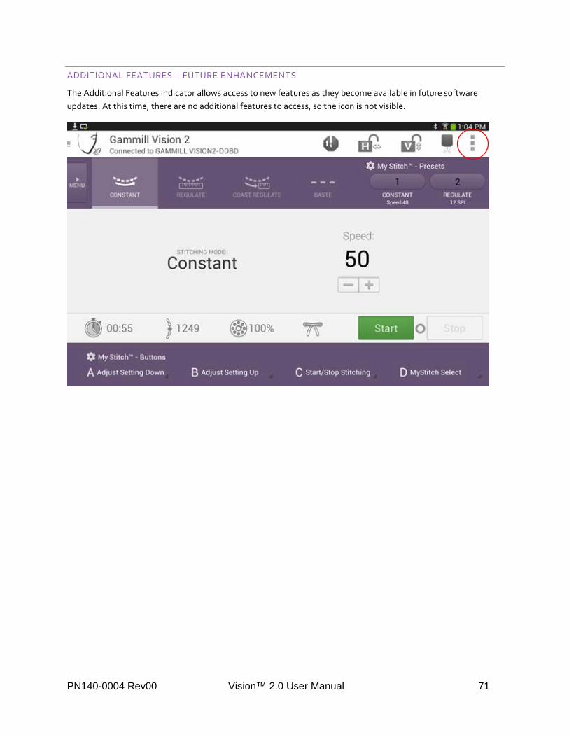
ADDITIONAL FEATURES – FUTURE ENHANCEMENTS
The Additional Features Indicator allows access to new features as they become available in future software updates. At this time, there are no additional features to access, so the icon is not visible.
PN140-0004 Rev00 Vision™ 2.0 User Manual 71

MAIN MENU
The Main Menu offers access to many of the settings and services not regularly used during quilting.
To access the Main Menu:
• Touch the Menu button.
PN140-0004 Rev00 Vision™ 2.0 User Manual 72

To select an item from the Main Menu:
• Touch the desired selection.
DETAILS ON ALL OF THE SCREENS FOUND IN THIS MENU CAN BE FOUND IN THE SETTINGS AND OTHER SCREENS SECTION.
PN140-0004 Rev00 Vision™ 2.0 User Manual 73

SETTINGS AND OTHER SCREENS
GENERAL NAVIGATION
To leave any secondary screen and return to the main screen, press the left arrow in the top left corner of the screen.
PN140-0004 Rev00 Vision™ 2.0 User Manual 74

GAMMILL VISION 2
The Gammill Vision 2 selection is a placeholder for the main window. As a result, it appears to do nothing when selected. This was required to properly set up the menu structure and is intentional.
ABOUT THIS APP
Access the About This App selection to learn information about your current version of the Vision™ 2.0 application and check for software updates.
To check for updates:
• Make sure the tablet is connected to the internet. • Touch the Check for Updates button. • Notice an update window opens indicating whether or not an update is available.
THIS FUNCTION REQUIRES THE TABLET TO BE CONNECTED TO THE INTERNET THROUGH A USER-SUPPLIED WIRELESS NETWORK. FOR INFORMATION ON HOW TO DO THIS, CONSULT THE DOCUMENTATION THAT CAME WITH THE TABLET OR SEE THE ENABLE WIRELESS ON TABLET SECTION IN THE VISION 2 SERVICE MANUAL FOR ADDITIONAL INFORMATION.
PN140-0004 Rev00 Vision™ 2.0 User Manual 75

To update the Vision™ 2.0 Application:
• Touch the YES button. • Notice the update begins downloading. • Please wait while the app is downloading from the Gammill website.
PN140-0004 Rev00 Vision™ 2.0 User Manual 76

THE DOWNLOAD MAY BE CANCELLED AT ANYTIME BY PRESSING THE CANCEL DOWNLOAD BUTTON.
• Once downloaded, a window will appear for permission to install the update.
• Press Install to begin the update.
PN140-0004 Rev00 Vision™ 2.0 User Manual 77

The app will be automatically updated and prompt you when complete.
To open the updated app:
• Tap the Open button.
PN140-0004 Rev00 Vision™ 2.0 User Manual 78

If no update is found, a message will pop up to let you know:
If a new machine firmware update is included within the new application, the application will prompt you with the steps to update the firmware.
To Update Firmware:
• Press OK to begin the update.
PN140-0004 Rev00 Vision™ 2.0 User Manual 79

ONCE STARTED, DO NOT INTERRUPT THE UPDATE BY USING THE TABLET OR MACHINE.
ONCE THE UPDATE IS COMPLETE, THE BLUETOOTH CONTROL BOARD WILL AUTOMATICALLY RESET AND RECONNECT TO THE APPLICATION.
PN140-0004 Rev00 Vision™ 2.0 User Manual 80

ALERTS
All alerts can be adjusted or disabled according to your needs.
To adjust the volume of alert sounds:
• Drag the bubble on the slider. • Dragging the slider to the left will lower the volume. • Dragging the slider to the right will increase the volume.
PN140-0004 Rev00 Vision™ 2.0 User Manual 81

To disable an alert:
• Touch an alert icon. • With each press, the alarm will toggle between on and off. • Notice the indicator below the alarm icon indicates whether it is on or off.
To adjust the Thread Break Sensor Delay:
• Press the – (minus) button to decrease the delay making the sensor more sensitive. • Press the + (plus) button to increase the delay making the sensor less sensitive.
PN140-0004 Rev00 Vision™ 2.0 User Manual 82

TO GENERATE A THREAD BREAK ALARM, THE SYSTEM LOOKS AT THE NUMBER OF STITCHES VERSUS THE MOVEMENT OF THE THREAD BREAK SENSOR. IF YOU HAVE FALSE ALERTS WHEN MAKING LOTS OF SMALL, FAST STITCHES OR WHEN USING VERY FINE THREAD, INCREASING THIS VALUE SHOULD HELP ALLEVIATE THESE FALSE ALERTS.
PRESS THE RESET TO DEFAULTS BUTTON TO RESET ALL SETTINGS ON THIS SCREEN TO THE FACTORY DEFAULTS. TO EXIT THE SCREEN WHEN YOU ARE FINISHED MAKING CHANGES, PRESS THE LEFT ARROW AT THE TOP LEFT OF THE SCREEN.
PN140-0004 Rev00 Vision™ 2.0 User Manual 83

NEEDLE SETTINGS
Customize various aspects of the needle movement and functions by accessing the Needle Settings screen.
Adjust Needle Position Speed:
• Press the + (plus) button to increase the needle to position faster. • Press the – (minus) button to adjust the needle to position slower. • Note: the General setting controls all stitching modes except basting. • Note: the Baste setting controls only the basting mode.
THIS IS AN ADVANCED SETTING, AND THE VALUE IS NORMALLY REDUCED TO ACCOUNT FOR WEAR WITHIN A MACHINE AS THE MACHINE AGES. IT IS NOT RECOMMENDED THAT YOU CHANGE THIS SETTING, UNLESS DIRECTED BY A GAMMILL TECHNICIAN.
PN140-0004 Rev00 Vision™ 2.0 User Manual 84

To Reset Defaults:
• Press the Reset to Defaults button to reset all settings on this screen to the factory defaults.
TO EXIT THE SCREEN WHEN YOU ARE FINISHED MAKING CHANGES, PRESS THE LEFT ARROW AT THE TOP LEFT OF THE SCREEN.
PN140-0004 Rev00 Vision™ 2.0 User Manual 85

LASER SETTINGS
Adjust the intensity of the laser to compensate for your room’s brightness as well as to change the size of the laser dot.
C ! CAUTION Laser Radiation. Avoid direct exposure to beam.
To turn the laser on or off:
• Press the Laser On/Off button to turn the laser on. • Notice the indicator below the laser icon indicates whether it is on or off. • Press the Laser On/Off button to turn the laser off.
PN140-0004 Rev00 Vision™ 2.0 User Manual 86

To adjust the laser brightness:
• Press the + (plus) to increase brightness and increase the size of the laser point. • Press the – (minus) to decrease brightness and decrease the size of the laser point.
PN140-0004 Rev00 Vision™ 2.0 User Manual 87

To reset defaults:
• Touch the Reset to Defaults button to reset all settings on this screen to the factory defaults.
TO EXIT THE SCREEN WHEN YOU ARE FINISHED MAKING CHANGES, PRESS THE LEFT ARROW AT THE TOP LEFT OF THE SCREEN.
PN140-0004 Rev00 Vision™ 2.0 User Manual 88

DISPLAY SETTINGS
Select the color used on the colored bars of the main screen in the Display Settings screen.
To select a color:
• Touch a colored box.
• Touch the Reset to Defaults button to reset the main screen color to purple.
PN140-0004 Rev00 Vision™ 2.0 User Manual 89

To exit the screen, press the left arrow at the top left of the screen.
PN140-0004 Rev00 Vision™ 2.0 User Manual 90

BLUETOOTH SETUP
The Bluetooth Setup allows the user to connect the tablet user interface to a machine. When chosen, a popup window will appear. This popup window will display all the available machines identified by the software.
TOUCH THE LISTING FOR THE MACHINE YOU WANT TO CONNECT TO. IF YOU HAVE MULTIPLE MACHINES THAT YOU COULD CONNECT TO, CONSULT THE ADDRESS PRINTED ON THE MACHINE DECAL AT THE REAR OF THE HEAD TO DETERMINE WHICH ADDRESS YOU WANT TO CONNECT TO.
THE POPUP WINDOW WILL DISAPPEAR, AND THE USER INTERFACE WILL BE CONNECTED TO THE MACHINE. WHEN THIS IS COMPLETE, THE USER INTERFACE WILL SHOW THE CONNECTION IN THE UPPER LEFT CORNER OF THE SCREEN UNDER THE MACHINE NAME.
PN140-0004 Rev00 Vision™ 2.0 User Manual 91

PN140-0004 Rev00 Vision™ 2.0 User Manual 92

QUICK START GUIDE
Access the onboard Quick Start Guide for basic instructions in threading, oiling and interface navigation.
• The Quick Start Guide opens in a separate app. • Swipe to scroll and pinch to zoom. • Press the back arrow at the top left to return to the Vision™ 2.0 app.
PN140-0004 Rev00 Vision™ 2.0 User Manual 93

SERVICE & MAINTENANCE SCREENS
NAVIGATION
The Service & Maintenance Screens are accessed through the main menu.
THESE SCREENS ARE USED WHEN DIAGNOSING POSSIBLE ISSUES WITH YOUR GAMMILL VISION 2 MACHINE. NORMALLY, THEY ARE TO BE USED UNDER THE DIRECTION OF A TECHNICIAN, BUT NO HARM CAN COME TO THE MACHINE AS LONG AS YOU FOLLOW THE DIRECTIONS.
WHEN THE SCREEN IS ACCESSED, THE BUTTONS AND SENSORS TAB IS SELECTED AS A DEFAULT. DIFFERENT FUNCTIONS MAY BE ACCESSED BY CLICKING ON THEIR CORRESPONDING TABS AT THE TOP OF THE SCREEN.
PN140-0004 Rev00 Vision™ 2.0 User Manual 94

PN140-0004 Rev00 Vision™ 2.0 User Manual 95

BUTTONS AND SENSORS
The Buttons and Sensors tab allows you to identify issues with the various sensors and buttons on the machine.
To check the Encoder Position:
• Move the machine to the left and right. • Notice the green indicator on the encoder position moves left to right as you move the machine. This
verifies that the X encoder is working properly. • Move the machine to the front and rear. • Notice the green indicator on the encoder position moves up and down as you move the machine. This
verifies that the Y encoder is working properly.
PN140-0004 Rev00 Vision™ 2.0 User Manual 96

To check Handle Buttons:
• Press each handle button. • Notice that as the button is pressed, the corresponding indicator turns green. This verifies that all
buttons are functioning properly.
To check the Needle Position:
• Slowly turn the hand wheel by hand. • Observe if the Up and Down needle position sensors turn green, and that they turn green at the correct
needle positions.
PN140-0004 Rev00 Vision™ 2.0 User Manual 97

To check Thread Movement:
• Turn the thread break wheel.
THE THREAD MOVEMENT COUNT WILL EITHER INCREASE OR DECREASE (DEPENDING ON DIRECTION ROTATED) BY 11 FOR EACH ROTATION OF THE WHEEL. THIS VERIFIES THAT THE THREAD BREAK ENCODER IS WORKING PROPERLY.
To exit Buttons and Sensors:
• Touch the left arrow at the top left of the screen.
PN140-0004 Rev00 Vision™ 2.0 User Manual 98
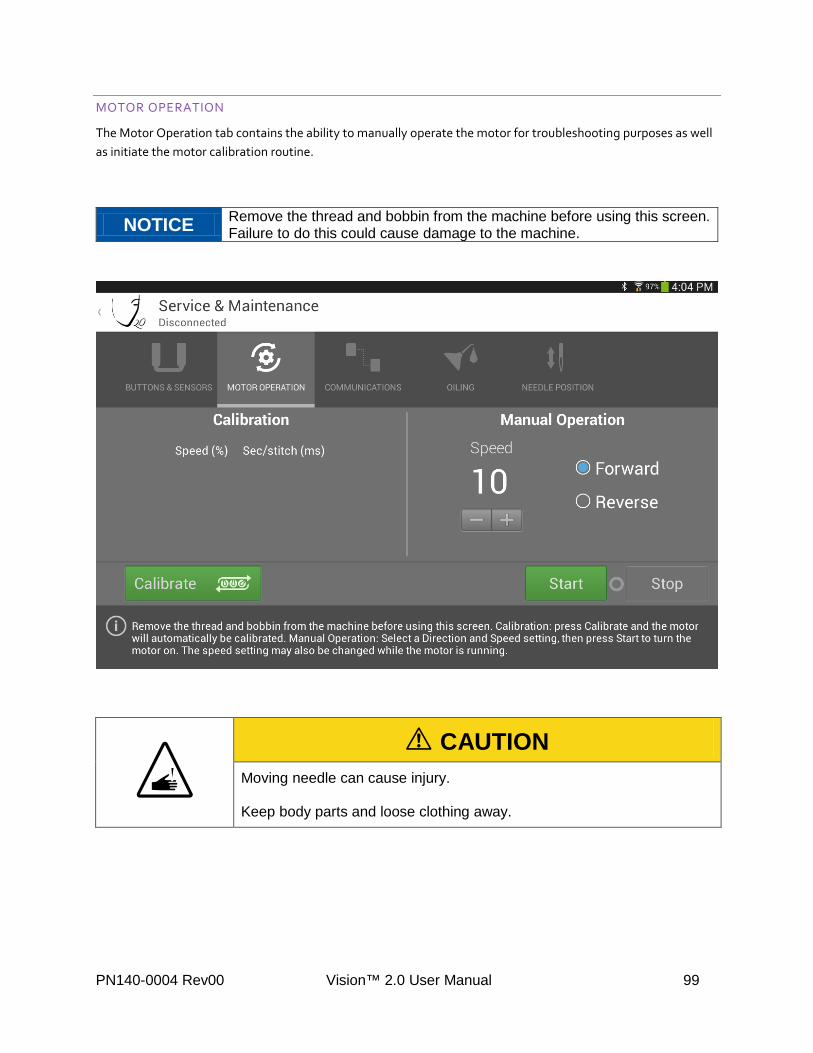
MOTOR OPERATION
The Motor Operation tab contains the ability to manually operate the motor for troubleshooting purposes as well as initiate the motor calibration routine.
NOTICE Remove the thread and bobbin from the machine before using this screen. Failure to do this could cause damage to the machine.
: ! CAUTION
Moving needle can cause injury. Keep body parts and loose clothing away.
PN140-0004 Rev00 Vision™ 2.0 User Manual 99

To manually run the motor:
• Touch Forward or Reverse to select a direction.
• Press the – (minus) or + (plus) to select the speed to run at.
PN140-0004 Rev00 Vision™ 2.0 User Manual 100

• Press the Start button on the screen. • When you are ready to stop running, press the Stop button.
THE SPEED MAY BE ADJUSTED WHILE RUNNING, BUT THE MOTOR MUST BE STOPPED TO CHANGE THE DIRECTION.
PN140-0004 Rev00 Vision™ 2.0 User Manual 101

To initiate the motor calibration routine:
• Press the Calibrate button on the screen.
• A popup will appear, to confirm you are ready to begin calibration. If so, press Start Motor Calibration. • If not, press Cancel.
PN140-0004 Rev00 Vision™ 2.0 User Manual 102

The calibration routine will run automatically, displaying results as it progresses.
IF YOU RUN THE CALIBRATION AND WANT TO THEN RUN THE MANUAL OPERATION, PRESS RESET TO ACCESS THE MANUAL OPERATION SPEED ADJUSTMENTS.
PN140-0004 Rev00 Vision™ 2.0 User Manual 103

COMMUNICATIONS
Use the communications tab to verify that the internal machine communications are working properly.
THIS SCREEN IS USEFUL TO DIAGNOSE AN INTERMITTENT CONNECTION PROBLEM WITHIN THE MACHINE, OR A CIRCUIT BOARD THAT MAY BE FAILING.
To test Communications:
• Notice the boxes are already checked. To exclude any of the communication devices, uncheck the box. • Leave all boxes selected to test the entire system.
PN140-0004 Rev00 Vision™ 2.0 User Manual 104

• Press the Scan button.
PN140-0004 Rev00 Vision™ 2.0 User Manual 105

• The test will automatically run showing progress and results. The messages received should be equal to the messages sent. If they are not equal, communication was lost between the device and the Bluetooth Control Board.
• Touch the Reset button to retest the communication system.
PN140-0004 Rev00 Vision™ 2.0 User Manual 106

To exit and return to the main screen, press the left arrow at the top left of the screen.
PN140-0004 Rev00 Vision™ 2.0 User Manual 107
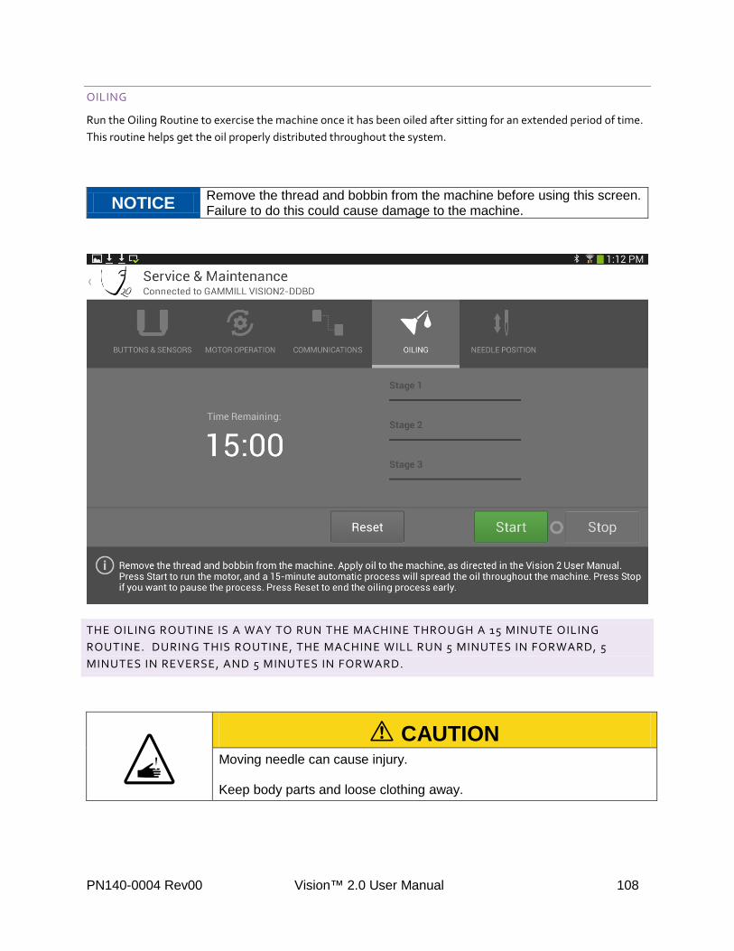
OILING
Run the Oiling Routine to exercise the machine once it has been oiled after sitting for an extended period of time. This routine helps get the oil properly distributed throughout the system.
NOTICE Remove the thread and bobbin from the machine before using this screen. Failure to do this could cause damage to the machine.
THE OILING ROUTINE IS A WAY TO RUN THE MACHINE THROUGH A 15 MINUTE OILING ROUTINE. DURING THIS ROUTINE, THE MACHINE WILL RUN 5 MINUTES IN FORWARD, 5 MINUTES IN REVERSE, AND 5 MINUTES IN FORWARD.
: ! CAUTION
Moving needle can cause injury. Keep body parts and loose clothing away.
PN140-0004 Rev00 Vision™ 2.0 User Manual 108

To run the Oil Routine:
• Fill all oiling points on the machine. See Oiling Instructions on page 11. • Touch the Start button.
• The machine will go through the routine and show the progress. When the routine is complete, the machine will automatically stop running.
PN140-0004 Rev00 Vision™ 2.0 User Manual 109
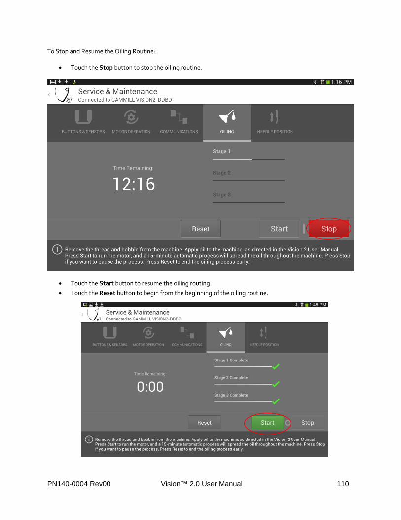
To Stop and Resume the Oiling Routine:
• Touch the Stop button to stop the oiling routine.
• Touch the Start button to resume the oiling routing. • Touch the Reset button to begin from the beginning of the oiling routine.
PN140-0004 Rev00 Vision™ 2.0 User Manual 110

To exit and return to the main screen, press the left arrow at the top left of the screen.
STAGE 1 RUNS THE MACHINE FORWARD FOR 5 MINUTES. STAGE 2 RUNS THE MACHINE IN REVERSE FOR 5 MINUTES. STAGE 3 RUNS THE MACHINE FORWARD FOR 5 MINUTES.
PN140-0004 Rev00 Vision™ 2.0 User Manual 111

NEEDLE POSITION
Automatically verify that the needle position sensors are working and adjusted properly by using the Needle Position tab.
NOTICE Remove the thread and bobbin from the machine before using this screen. Failure to do this could cause damage to the machine.
:
! CAUTION
Moving needle can cause injury. Keep body parts and loose clothing away.
PN140-0004 Rev00 Vision™ 2.0 User Manual 112

To test the Needle Sensors:
• Touch the Start button.
THE MACHINE WILL RUN AN AUTOMATED TEST AND STOP WHEN COMPLETE. THE DISPLAY WILL SHOW THE VALUES FOR THE UP AND DOWN SENSORS IN GREEN OR RED TO SHOW PASS/FAIL STATUS.
• Touch the Stop button to stop the test while running.
PN140-0004 Rev00 Vision™ 2.0 User Manual 113

• Touch the Start button to restart the test.
IF THE VALUE IS GREEN, AND FOLLOWED BY A CHECKMARK, THE TEST HAS PASSED. IF THE VALUE IS RED AND FOLLOWED BY AN X, THE TEST HAS FAILED. IN THE EVENT OF A FAILURE, CONSULT THE VISION 2 SERVICE MANUAL FOR FURTHER STEPS.
To exit and return to the main screen, press the left arrow at the top left of the screen.
PN140-0004 Rev00 Vision™ 2.0 User Manual 114