Virtual Reality as a Tool for Verification of Assembly and...
25
Virtual Reality as a Tool for Verification of Assembly and Maintenance Processes Antonino Gomes de S´ a BMW AG, Geometrical Integration, CAD/CAM, 80788 Munich, Federal Republic of Germany, email: [email protected] Gabriel Zachmann Fraunhofer Institute for Computer Graphics, Rundeturmstraße 6, 64283 Darmstadt, Federal Republic of Germany, email: [email protected] Abstract Business process re-engineering is becoming a main focus in today’s efforts to over- come problems and deficits in the automotive and aerospace industries (e.g., inte- gration in international markets, product complexity, increasing number of product variants, reduction in product development time and cost). In this paper, we investigate the steps needed to apply virtual reality (VR) for virtual prototyping (VP) to verify assembly and maintenance processes. After a review of today’s business process in vehicle prototyping, we discuss CAD-VR data integration and identify new requirements for design quality. We present several new interaction paradigms so that engineers and designers can experiment naturally with the prototype. Finally, a user survey evaluates some of the paradigms and the acceptance and feasibility of virtual prototyping for our key process. The results show that VR will play an important role for VP in the near future. Key words: Virtual environments, virtual prototyping, digital mock-ups, assembly and maintenance process, user acceptance, direct manipulation. 1 Introduction In order to stay competitive on international markets, companies must deliver new products with higher quality in a shorter time with a broader variety of
Transcript of Virtual Reality as a Tool for Verification of Assembly and...

Virtual Reality as a Tool for
Verification of Assembly and Maintenance
Processes
Antonino Gomes de Sa
BMW AG, Geometrical Integration, CAD/CAM, 80788 Munich, Federal Republicof Germany, email: [email protected]
Gabriel Zachmann
Fraunhofer Institute for Computer Graphics, Rundeturmstraße 6, 64283Darmstadt, Federal Republic of Germany, email: [email protected]
Abstract
Business process re-engineering is becoming a main focus in today’s efforts to over-come problems and deficits in the automotive and aerospace industries (e.g., inte-gration in international markets, product complexity, increasing number of productvariants, reduction in product development time and cost).
In this paper, we investigate the steps needed to apply virtual reality (VR) forvirtual prototyping (VP) to verify assembly and maintenance processes. After areview of today’s business process in vehicle prototyping, we discuss CAD-VR dataintegration and identify new requirements for design quality. We present several newinteraction paradigms so that engineers and designers can experiment naturally withthe prototype.
Finally, a user survey evaluates some of the paradigms and the acceptance andfeasibility of virtual prototyping for our key process. The results show that VR willplay an important role for VP in the near future.
Key words: Virtual environments, virtual prototyping, digital mock-ups, assemblyand maintenance process, user acceptance, direct manipulation.
1 Introduction
In order to stay competitive on international markets, companies must delivernew products with higher quality in a shorter time with a broader variety of

versions at minimum costs. Virtual prototyping is quickly becoming an inter-esting strategy for product development. Automotive industries seem to beamong the leaders in applying virtual reality (VR) for real-world, non-trivialproblems 1 . Although there are already several commercial 3D engineeringtools for digital mock-up (and the number continues to grow), all of them lackone thing: intuitive direct manipulation of the digital mock-up by the human.Therefore, they are inherently inferior to VR for certain applications.
While some automotive companies have already begun to routinely use VRas a tool in styling and design reviews in the concept phase, it has not beenclear that VR can be an efficient tool in assembly/disassembly simulationsand maintenance verifications. Assembly simulations are much more difficultin that they involve a lot of interaction and real-time simulation. However, [2]revealed that the assembly process often drives the majority of the cost of aproduct. [13] point out that up to 70% of the total life cycle costs of a productare committed by decisions made in the early stages of design.
Definitions of virtual prototyping. There seem to be two different un-derstandings of what exactly virtual prototyping is: the “computer graphics”and the “manufacturing” point of view 2 . We will define the former as virtualprototyping, and the latter as digital mock-up (which is often confused withvirtual prototyping).
By virtual prototyping (VP) we understand the application of virtual realityfor prototyping physical mock-ups (PMUs) using product and process data.The VR system simulates and renders all characteristics relevant to the par-ticular context as precisely and realistically as possible in an immersive en-vironment [8]. Some examples are: verification of assembly and disassemblyprocedures, assessment of product characteristics (e.g., ergonomics), and vi-sualization of simulation data. The idea is to replace, at least partly, physicalmock-ups (PMUs) by software prototypes.
Digital mock-up (DMU) is a realistic computer simulation of a product withthe capability of all required functionalities from design/engineering, manu-facturing, product service environment, maintenance, and product recycling;DMUs are used as a platform for product and process development, for com-munication, and making decisions from a first conceptual layout [5]. This in-cludes all kinds of geometrical, ergonomic, and functional simulations, whetheror not involving humans.
1 After all, this seems only natural, since they have been also among the first whoapplied computer graphics.2 Actually, the term “virtual prototyping” is also used in other areas such as VLSIchip design.
2

So, immersive virtual prototyping is one of many techniques for implementingDMU.
Assembly/disassembly verification has several goals. The final goal, of course,is the assertion that a part or component can be assembled by a humanworker, and that it can be disassembled later-on for service and maintenance.However, other questions need to be addressed, too: is it “difficult” or “easy”to assemble/disassemble a part? How long does it take? How stressful is it interms of ergonomics? Is there enough room for tools?
2 Related Work
A lot of development for utilizing VR for VP is being realized by automotiveand aerospace companies. Many efforts, however, are still feasibility studies.
Practically all automotive companies investigate the use of VR for stylingreviews and other mere walk-through applications. Some of them already em-ploy it for daily work. Usually, the model is rendered on a large-screen stereoprojection or in a cave. Variations can be compared on the fly with realisticcolors and illumination effects [6]. At Daimler Benz the body of a car can bereviewed in an immersive virtual environment by the aid of zebra lighting [3].
Since VR provides an intuitive and immersive human-computer interface, it isperfectly suited to do ergonomics studies. Consequently, many projects capi-talize on this advantage of VR. Ford employs virtual prototypes with severalproposed dashboard configurations to verify visibility and reachability of in-strument.
Researchers at Caterpillar Inc. use VR to improve the design process for heavyequipment. Their system [11] allows them to quickly prototype wheel loaderand backhoe loader designs to perform visibility assessments of the new designin a collaborate virtual environment. Further the engineers can simulate theoperation of the equipment and evaluate visual obstructions.
Volkswagen has incorporated some useful applications in the vehicle devel-opment process. They have coupled a commercial human inverse kinematicpackage with VR to investigate different ergonomic features. They also visu-alize the results of FEA crash computations in VR interactively. The virtualproduct clinic avoids faulty developments and helps assess customers’ wishes[14].
Chrysler launched a project to study the process of virtual prototyping, toinvestigate the steps required for the creation of a virtual representation from
3
CAD models, and for the subsequent use of the prototype in immersive VR[6].
A vision of virtual prototyping was developed within the ESPRIT project AIT(Advanced Information Technologies in Design and Manufacturing). Projectpartners were many European automotive, aerospace, IT suppliers, and academia[5]. A lot of visionary prototypes have been presented also by [1].
A prototype virtual assembly system is described in [9]. Our approach inte-grates many more interaction paradigms, and we present the results of a usersurvey evaluating some of them. Although they do not describe the process ofauthoring a virtual environment, it seems to us that they pursue the toolboxapproach, i.e., the system is a monolithic program on top of a set of libraries,while our approach is the scripting approach.
Systems for designing in VR are presented by [4,19]. Our approach is to useVR only for investigation and simulation. No geometry can be designed by oursystem, because we do not feel that this would take advantage of the strengthsof VR. A factory simulation for immersive investigation has been presentedby [10]. Although no direct manipulation with objects is possible, problemscan be identified earlier than through the aid of charts and graphs producedby conventional simulations.
3 Assembly Processes in the Automotive Business Process
Today’s computer-aided tools (CAx) for automotive and other industries cansimulate a lot of the functions and operating conditions of a new product.In some cases, software simulations are as good or even better than physicalmock-ups. However, they still do not meet all requirements to avoid PMUscompletely. Certain functions of a new product cannot be simulated at allby current CAx tools, while others don’t provide the results in an acceptabletime.
Therefore, many PMUs are built during the development process to achievea 100% verification of the geometry, the functions, and the processes of anew car project. Additionally, today’s CAx tools do not provide a natural andintuitive man-machine interface that allows the user to feel and to get thespatial presence of the virtual product.
In order to “fill” these gaps, many automotive and other companies haveestablished projects to investigate the use of VR technologies for verificationof designs and processes [7].
4

SF SF SFDF DF DF
Time
Series Start Series End
Concept DesignDetailed
Engineering
Design
ManufacturingMaintenance/Recycling/
Further Developments
D e s i g n / C A D
C A - P r o t o t y p e
P h y s i c a l M o c k - u p P r o c e s s
Semi-prototypes Prototypes Pre-series
Semi-prototypes
Prototypes Pre-series
Legend:
S
-
F - StylingFreeze
DF - DesignFreezeDeadline�
Vehicle
Prototype
D e s i g n / C A D
C A P t t
Fig. 1. Process chain for the vehicle prototype activities.
Today’s approach
The automotive business process chain comprises various key-processes fromthe early concept phase through final service, maintenance and recycling.Those that will be highlighted in this paper are the assembly and mainte-nance processes. The verification process can be broken down into three sub-processes which are described in the following (see Figure 1):
• Fast CA loops. CAx tools are used to quickly verify different design conceptsand assembly/disassembly of the design concepts. These verifications takeplace in-between the design and the CA prototype process (see Figure 1). Atthe beginning of the business process chain the freedom to change conceptsand the number of variations of a component is higher. Due to this fact thenumber of CA verifications during the development process will decrease.
• PMU loops. For detail verification of design concepts and assembly processesin some sections of a product, various PMUs are built. This sub-processcan be identified in Figure 1 between the design and the physical mock-upprocess (see dashed line).
• PMU verification. Some complete PMUs of the final product (e.g., a car)are built to verify if all the designed components fulfil all the requirementsrelated to ergonomics, functions and processes. Before these full prototypesare built, a freeze of the styling and design processes occurs. In Figure 1these phases are marked by the deadlines SF and DF.
5

In the traditional process chain several problems arise due to the fact thatverifications of the processes are made using PMUs and CAx tools:
• Parallel verification processes. Verifications are made with CAx tools andwith PMUs (in this case they are obtained by e.g. the use of rapid prototypetechniques and/or hand-built prototypes) concurrently. The correlation be-tween this two verification processes is very hard to obtain.
• Not enough co-ordination. The handling, synchronisation, correlation, andmanagement of these processes is very difficult and in some cases impossible.In order to build a PMU a design stage needs to be freezed. At this time,the building of the PMU starts and can take 6 to 12 weeks. Due to concur-rent engineering, further changes of CAD parts (sometimes even significantones) can be made during the build-time. Therefore, by the time results areobtained by the PMU verification they have no more a direct correlation tothe current design. Even if there have not been changes in the design, the“transfer” of the results of the PMU verification to the DMU is, in somecases, very difficult.
Vision
Most companies already define their products digitally (e.g., CA methods)and manage the data by product data management systems (PDM). How-ever, the digital data are not used as the basis for the core business process.Instead, they are maintained in parallel to a more traditional process basedon physical mock-ups, more as an auxiliary or “support” of the PMU processor the building of PMUs.
The goal of DMU is to replace the traditional business process, based onPMUs, by one which fully maximizes DMU technologies available today andin the future. The visionary goal is a process with only a single PMU for a finalverification, certification, and release to volume manufacturing (see Figure 2).
The goal is to perform verifications as early as possible, i.e., front-loading ofengineering, manufacturing, service, manufacturing, and recycling tasks to theconcept phase [5]. We believe that by utilizing VR, digital mock-ups can beevaluated in the concept phase.
Objectives of the verification of assembly processes
Objectives can be classified by two categories: strategic and operative.
Strategic objectives are global and involve the complete business process. Themost important ones are: reduction of development costs, development time,and time-to-market; increase of product innovation, product quality, flexibility,
6

Time
Time
Series Start
Series Start
Series End
Series End
PMU
PMU
PMU
DMU
DMU
DMU
? ? ??
Today:�
�
�
PMU=LeaderParallel ProcessNo Correlation
Tomorrow:�
�
�
DMU=LeaderParallel ProcessCorrelation HW/SW
Goal:
�
�
�
DMU=Leader
One final verification in HW
Final correlation HW/SW
Concept Phase Engineering Manufacturing Service/Recycling
Fig. 2. Transition from physical to digital mock-up [5].
and maturity at series start.
Operative objectives are more local, related to only one or a few key-processes.The most important objectives which need to be fulfilled for assembly andmaintenance are [12]:
• service, inspection, and repair locations should be easily accessible;• visibility should be ensured;• exchange of components should be easy;• use few and standard service and inspection tools;• accessibility of service tools, and hand and arm of the worker;• calculation and investigation of minimal distances to avoid collisions, e.g.
during operating conditions;• calculation of assembly/disassembly paths for off-line robot-programming;• calculation of sweeping envelop of movable component for packaging inves-
tigations, e.g. for reservation of space in engine bay.
Additionally, these objectives must be verified with 1–20mm precision, relatedto the business process phase . They must be documented in digital form.These electronic reports should be managed by the PDM system togetherwith the geometry and further administrative and technological data. As soonas a new version of a electronic report is created, the PDM system shouldinform involved users, that a new report is available for assembly processes.
7
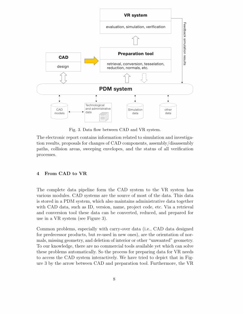
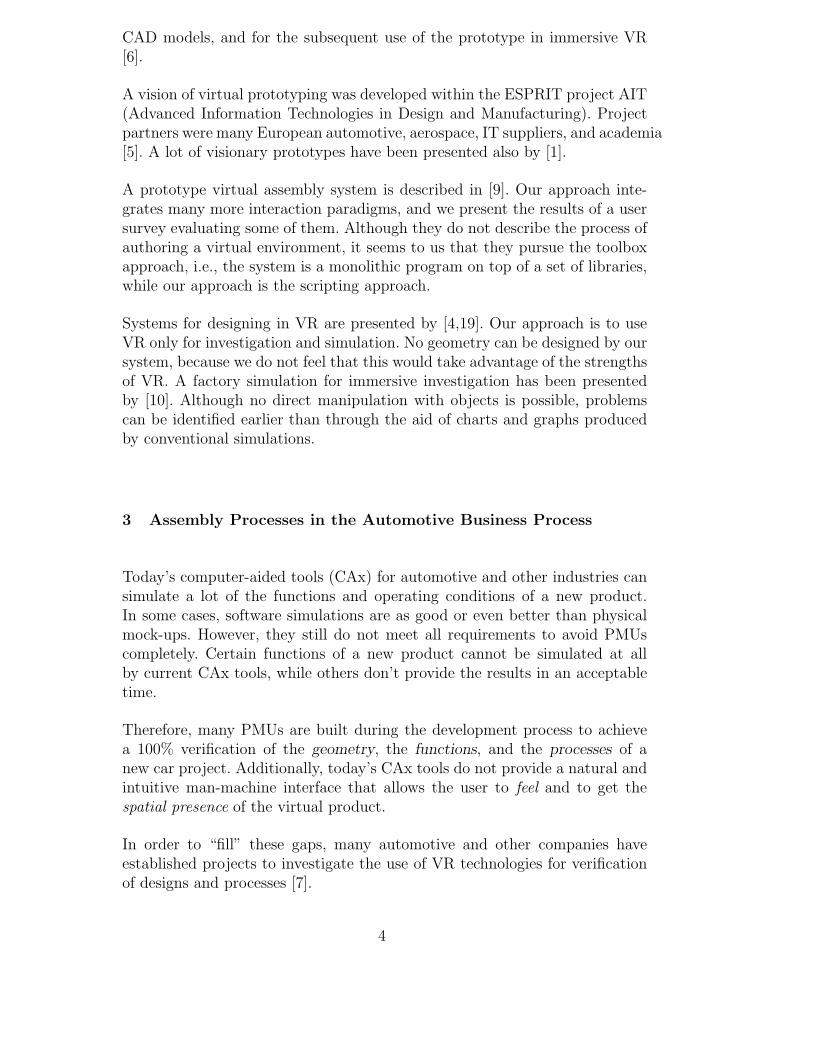
Fig. 3. Data flow between CAD and VR system.
The electronic report contains information related to simulation and investiga-tion results, proposals for changes of CAD components, assembly/disassemblypaths, collision areas, sweeping envelopes, and the status of all verificationprocesses.
4 From CAD to VR
The complete data pipeline form the CAD system to the VR system hasvarious modules. CAD systems are the source of most of the data. This datais stored in a PDM system, which also maintains administrative data togetherwith CAD data, such as ID, version, name, project code, etc. Via a retrievaland conversion tool these data can be converted, reduced, and prepared foruse in a VR system (see Figure 3).
Common problems, especially with carry-over data (i.e., CAD data designedfor predecessor products, but re-used in new ones), are the orientation of nor-mals, missing geometry, and deletion of interior or other “unwanted” geometry.To our knowledge, there are no commercial tools available yet which can solvethese problems automatically. So the process for preparing data for VR needsto access the CAD system interactively. We have tried to depict that in Fig-ure 3 by the arrow between CAD and preparation tool. Furthermore, the VR
8

representation of CAD data and the configuration of the virtual environmentneed to be managed within the PDM systems (dashed arrow in the figure).
CAD data requirements
Design data available today in the manufacturing industries and others do notmeet the geometric and non-geometric requirements so they can be used as-isfor a VR simulation. There are two ways to tackle the problems described inthe previous section: new data must be designed with virtual prototyping inmind; old data must be dealt with, either by redesigning (least preferred), orby semi-automatic conversion to representations suitable for VR.
It is commonly understood that design data has to have different representa-tions depending on the phase in the business process (e.g., concept, engineer-ing, etc.) and the key process that is to be verified [15]. For example, in thesame CAD model there should be geometry and non-geometric information,like kinematic constrains, material properties, weight, etc., that will be usedlater-on during a VR session.
To avoid that designers have to become familiar with different software tools,the number of interfaces must be kept low. To achieve that an the two worldsneed to be integrated, at least to a higher degree than present today. Ideally, adesigner can create the CAD components and also perform assembly feasibilitystudies, himself. Also, with a better integration it will be easier to exchangedata between CAD/PDM systems and VR systems.
5 Immersive Verification
In this section, we will briefly explain the process of authoring VEs, presentthe two scenarios which have been chosen for our studies and developments,and finally describe the functionality needed for assembly investigations.
5.1 Authoring
In order to make virtual prototyping an efficient tool to save time, it mustbe easy to “build” a virtual prototype, i.e., a virtual environment (VE) whichrepresents part of a car and simulates part of its physical behavior. It mustbe at least as easy as designing with a CAD system.
We have developed a three-layer framework; each layer provides a certain levelof abstraction and specialization. It has proven to be flexible and powerful.
9

application layer (appl.-specific user interface)
scene graph layer (CAD interface)
scripting layer (general user interface)
Fig. 4. We have identified three layersof increasing abstraction and special-ization, on which authoring of a virtualenvironment takes place.
Actions Events
Scene Graph
Fig. 5. The AEO framework. Note thatactions are not “tied-in” with graphicalobjects.
Fig. 6. For every application domain there must be an application-specific authoringtool which provides the type of high-level functions needed in the particular domain.
The bottom layer is the scene graph: it deals mostly with geometry and ren-dering optimizations. Some scene graph APIs, such as VRML2.0 or Inventor,also provide very low-level scripting features (for instance routes and engines).
At the next level we have implemented the event-based scripting approach forbuilding VEs [16]. It is a general framework based on the concept of objects,actions, and events, each of which with higher-level, yet general “story-boarddriven” functionality.
End-users working in a certain application domain (such as assembly simula-tion) will specify scenarios at the application layer, which provides a graphicaluser-interface (see Figure 6) and specialized, very high-level functionality (e.g.,the user tells the system which objects are tools).
Scenario templates
Another way to tackle the problem of authoring might be scenario templates.The idea is, if parts had standard names, then a large portion of VEs couldbe derived from standard “scenario templates”, e.g., “front door”, “tail light”,“gear box”, etc. So, for a VR session with a different geometry, a VE author
10
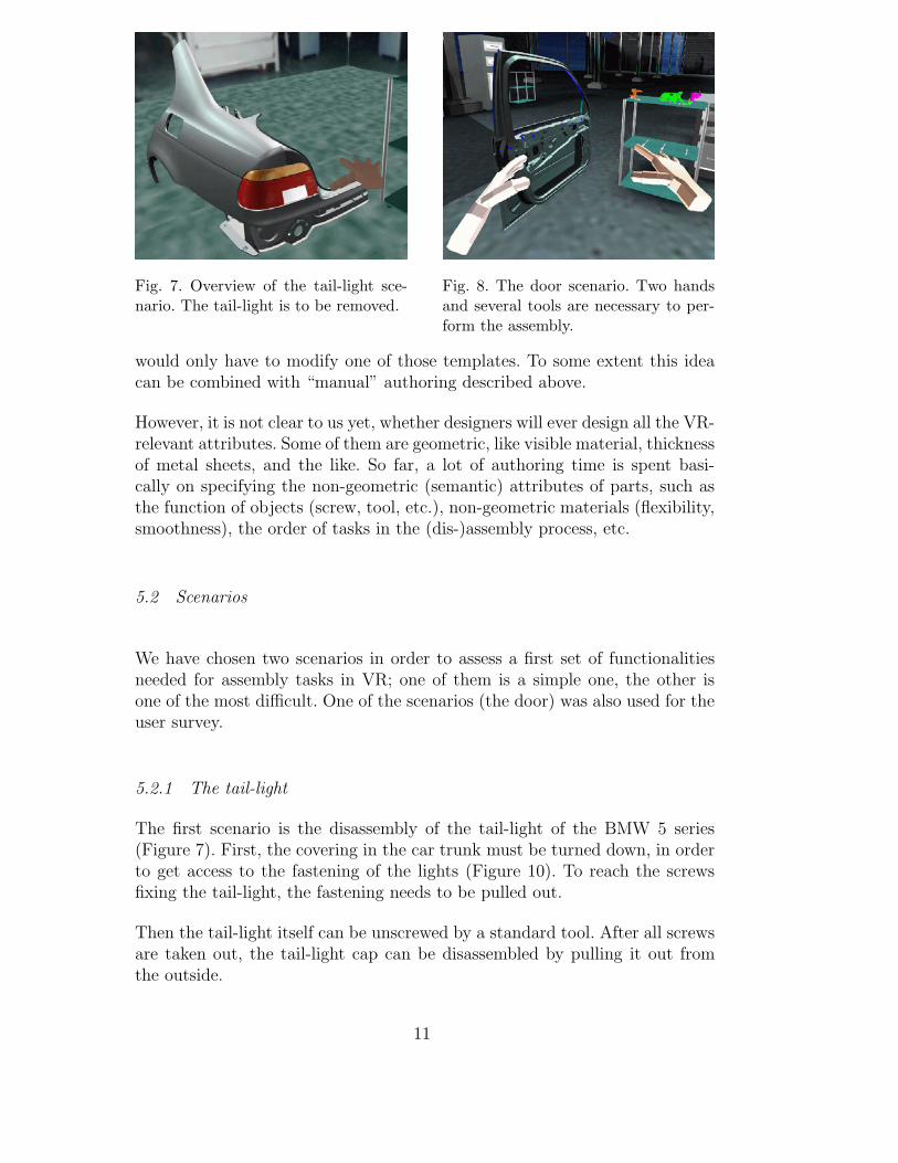
Fig. 7. Overview of the tail-light sce-nario. The tail-light is to be removed.
Fig. 8. The door scenario. Two handsand several tools are necessary to per-form the assembly.
would only have to modify one of those templates. To some extent this ideacan be combined with “manual” authoring described above.
However, it is not clear to us yet, whether designers will ever design all the VR-relevant attributes. Some of them are geometric, like visible material, thicknessof metal sheets, and the like. So far, a lot of authoring time is spent basi-cally on specifying the non-geometric (semantic) attributes of parts, such asthe function of objects (screw, tool, etc.), non-geometric materials (flexibility,smoothness), the order of tasks in the (dis-)assembly process, etc.
5.2 Scenarios
We have chosen two scenarios in order to assess a first set of functionalitiesneeded for assembly tasks in VR; one of them is a simple one, the other isone of the most difficult. One of the scenarios (the door) was also used for theuser survey.
5.2.1 The tail-light
The first scenario is the disassembly of the tail-light of the BMW 5 series(Figure 7). First, the covering in the car trunk must be turned down, in orderto get access to the fastening of the lights (Figure 10). To reach the screwsfixing the tail-light, the fastening needs to be pulled out.
Then the tail-light itself can be unscrewed by a standard tool. After all screwsare taken out, the tail-light cap can be disassembled by pulling it out fromthe outside.
11

5.2.2 The door
This scenario is much more complex and more difficult in that both hands andvarious tools must be utilized (Figure 8).
The first task is to put the lock in its place in the door. This is quite difficult inthe real world, because it is very cramped inside the door and the lock cannotbe seen very well during assembly. Screws have to be fastened while the lockis held in its place (Figure 12).
Next, the window-regulator is to be installed (Figure 13). This task needs bothhands, because the window-regulator consists of two parts connected to eachother by flexible wires. After placing the bottom fixtures into slots, they mustbe turned upright, then the regulator screws can be fixed.
Finally, several wires must be layed out on the inner metal sheet, clipped intoplace, and connected to various parts. However, this part of the assembly wasnot performed in VR.
5.3 Interaction Functionality
In this section, we will describe an array of techniques most of which haveproven to be helpful in verification of assembly simulations.
Multi-modal interaction. It is important to create an efficient human-computer interface, because the tasks to be performed in virtual prototypingcan be quite complex. Many of the “classic” VR interaction techniques canbe utilized, such as (static) gesture recognition, 3D menus, selection by beamcasting, etc. Each technique must be implemented in a very robust and user-independent manner, otherwise users will become irritated and disapprovingof VR.
While grasping two objects with both hands, a user must still be able to givecommands to the computer. This can be achieved most intuitively by voicerecognition. Also, multi-sensory feedback (see below) plays an important rolein multi-modal interaction.
Getting help from the system. When the number of functions becomeslarge in the VR system, it happens that occasional users cannot remember acertain command. Similar to 2D applications, we additionally provide hierar-chical 3D menus. They are invoked by a speech command. In our experience,
12

Fig. 9. Administrativedata stored in the PDMabout parts can be dis-played during the VRsession.
Fig. 10. Inverse kine-matics is needed for“door-like” behavior ofparts.
Fig. 11. With the virtualyard-stick distances canbe measured in the VE.
3D menus are to be considered only as an auxiliary interaction technique, sinceit is more difficult to select menu entries in VR than it is in 2D.
An on-line service manual. We believe that VR could eventually becomean efficient means for training service personnel and creating an interactiveservice manual. Service manuals could be disseminated in the form of VRMLenvironments, which can be viewed and interacted with on a PC based “fish-tank” VR system. However, augmented reality based systems might be nec-essary, especially in larger and more complex vehicles, such as aircrafts andsubmarines.
In our environments we have implemented an interactive service manual aswell as an interactive training session. First, a trainee learns by watching theservice manual; this is basically an animation of the assembly process. Whilethe animation is being played back, the trainee can move freely about theenvironment and watch from any viewpoint.
When the trainee is ready to learn by doing, he will perform the task step bystep. After each step is completed the system will point him to the part or toolhe will need for the next step and tell him what to do with it. For instance,after all screws for the door lock have been fastened, the system highlightsthe window regulator (by blinking) and instructs him how to assemble it. Theinstructions have been pre-recorded and are played back as sound files.
So far, the virtual service manual and the interactive training session are hand-crafted via manual scripting. However, it should be straight-forward to extractthem from a PDM system, if the process data are there in a standardized form.
Investigation tools. In order to make the correct decisions, it is importantthat the user can get information about the parts involved in the virtual pro-totype currently being investigated. Administrative information about parts
13
can be displayed in a heads-up fashion by pointing at objects with a ray (seeFigure 9). Of course, any other selection paradigm can be used as well.
A tool which has been requested by designers is the clipping plane. It can helpto inspect “problem areas” more closely. When activated, the user “wears” aplane on his hand; all geometry in front of that plane will be clipped awayin real-time. Optionally, the part clipped away can be rendered transparently.Sometimes it can be necessary to restrict the motion of the plane so that it isalways perpendicular to one of the world coordinate axes.
Another tool to inspect assembly situations and the mechanical design is theuser size. This parameter can be controlled by simple speech commands, whichin turn affect all parameters by which a virtual human is represented, inparticular navigation speed and scale of position tracking. This way, a usercan comfortably “stick his head” inside some narrow space.
In order to measure distances we have implemented two options: A user canselect two objects, then the system will compute the minimal distance betweenthe two and display it in the heads-up display. Or, the user can grab a virtualyard stick (see Figure 11). While grabbed, the yardstick adjust its length inboth directions so that it just touches the closest geometry. Additionally, itslength is shown on the heads-up display. Another way would be to select twopoints on the geometry and have the system display the length of that line.
Physically-based simulation. Many mechanical components have somearticulated parts. These could be simple “door-like” mechanisms (see Fig-ure 10), i.e., permanent joints with one rotational degree of freedom (DOF),such as hoods, lids, etc.; other very simple ones are sliding mechanisms (onetranslational DOF), for example the seat of a car. Inverse kinematics of theseand other articulated chains can be simulated on-line.
For complicated kinematic simulation, such as the working conditions of acomplete chassis, we have pursued a different approach: the VR system loadsthe results of an off-line simulation by a commercial package, such as AdamsTM.The user can then interactively steer the visualization, for example by turningthe steering wheel or by speech commands.
A lot of the parts in a vehicle are flexible: wires, hoses, plastic tanks, etc. Itis still a major challenge to simulate all these different types of flexible partswith reasonable precision and at interactive rates. In particular, simulation ofthe interaction of flexible objects with the surrounding environment and theuser’s hands by a general framework is, to our knowledge, still unsolved.
We have implemented hoses and wires in our VR system; the wires or hosesare attached at both ends to other, non-flexible parts, and they can be pushed
14

Fig. 12. Tools snap ontoscrews and are con-strained. Also, they areplaced automatically atan ergonomic positionwithin the hand by thesystem.
Fig. 13. The windowregulator has to be in-stalled with two hands;the “ghost” paradigmsignales collisions.
Fig. 14. The ob-ject-on-the-leadparadigm allows toverify assembly. Theobject is not linkedrigidly to the hand.
or pulled by a user’s hand.
Verification without force-feedback. In our experience, assembly tasksare more difficult in VR than in the real in world, because in VR there isno force and haptic feedback (see also Section 6). Humans can even performquite complicated tasks without seeing their hands or tools merely based onauditory, haptic and kinaesthetic feedback. Therefore, we have provided a lotof interaction aids trying to compensate for the missing force feedback.
In order to help the user placing parts, we have developed two kinds of snap-ping paradigms: the first one makes objects snap in place when they are re-leased by the user and when they are sufficiently close to their final position.The second snapping paradigm makes tools snap onto screws when sufficientlyclose and while they are being utilized (see Figure 12). The second paradigmis implemented by a 1-DOF rotational constraint which can be triggered byevents.
The major problems is: how can we verify that a part can be assembled by ahuman worker? A simple solution is to turn a part being grasped into whatwe call a ghost when it collides with other parts: the solid part itself staysat the last valid, i.e., collision-free, position while the object attached to theuser’s hand turns wireframe (see Figure 13).
However, invalid positions can be “tunneled”. Therefore, we have developedobject-on-the-lead paradigm: the object is no longer attached rigidly to thevirtual hand; instead, it “follows” the hand as far as it can go without penetrat-ing any other parts (see Figure 14). We have implemented a physically-basedsimulation, so that the object can glide along other parts; in our earlier imple-mentation, there was no gliding, which caused the object on-the-lead to get
15

Fig. 15. During assem-bly, the path of any partcan be recorded, edited,and stored in the PDMsystem.
Fig. 16. Annotations canbe put into the scene byvoice commands.
Fig. 17. Violations of se-curity-distance are high-lighted by yellow, colli-sions are red.
stuck in tight environments. So, at any time it can assume only valid positions.Of course, exact and fast collision detection is a prerequisite [18].
This is only a first step. A completely reliable verification will check the virtualhand for collisions as well. Also, the hand and/or part should slide alongsmooth rigid objects to make assembly easier for the user.
Documentation. If a certain assembly task cannot be done, then the resultof the verification session should be a precise as well as intuitive understand-ing why that is. A number of techniques have been implemented in order toinvestigate and document a possible failure of assembly.
During assembly/disassembly the path of any part can be recorded and editedin VR (see Figure 15). Saved paths can then be stored in the PDM system.
While parts are being moved, the sweeping envelope can be traced out. Itdoes not matter whether the part is moved interactively by the user or on anassembly path.
Problems can be annotated by placing 3D markers (we have chosen 3D arrows).Then, verbal annotations can be recorded and displayed textually next to themarker (see Figure 16). Note that all interaction is done by the user via speechrecognition, except for placing the marker.
Feedback to the user. Any VR system should be as responsive as possible,especially for occasional, non-expert users. The users targeted for immersiveVP will probably not use VR every day. Therefore, multi-sensory feedback isimportant to make them feel comfortable and in control.
Therefore, the system acknowledges all commands, in particular those invokedvia voice recognition. Currently, this is done by pre-recorded audio or speech.
16

Eventually, we will utilize speech synthesis.
During the assembly simulation, a variety of feedbacks can be combined whichwill be given if the user tries to move an object at an invalid position: acous-tic feedback, tactile feedback by a CybertouchTM glove, and visual feedback.Visual feedback comes in several flavors: whole parts can be highlighted (seeFigure 17), or the polygons which would have intersected at the invalid posi-tion can be highlighted.
6 User-Survey
In order to evaluate the acceptance and the potential of VR for VP, a surveyof prospective users has been performed at BMW.
We chose representatives from each of five groups involved with assembly andmaintenance investigations.
• CA specialist (CA). These are engineers that have a good CAx expertiseand also some specific assembly/maintenance processes knowledge.
• Skilled worker (SW). These are skilled mechanics who actually perform thephysical prototype verifications. This group has no CAx knowledge.
• Interface specialist (IS). This group comprises mechanical technicians. Theyhave mostly specific assembly/maintenance process knowledge, but they arestarting to get familiar with CAx tools. This group mediates between group1 and group 2.
• Managers (MA). They are the ones that co-ordinate all three groups in thevehicle prototype group.
• IT specialists (IT). In this group are very highly skilled engineers that dodevelopment and evaluation of new CAx methods and IT tools. They pro-vide new technologies to the key-user’s departments (the above four groupsare from the key-user department vehicle prototype).
Notice that all subjects have never before been exposed to any VR experiences.This was because the base of subject with VR experiences is insufficiently smallfor a survey.
The average (AVG) of all groups will be presented in some figures.
The scenario used for the survey was the installation of the door lock, whichis a very difficult task, because the space inside the door is very tight. Onlysubjects from group SW were to completely install the lock with their “virtualhand”, because they are the only ones who really know how to do it. For allother groups, subjects were to focus on the “feel” of the technology, the I/O
17

devices, and interaction techniques and capabilities.
Each group consisted of 5-7 persons, which gives a total of approximately 30persons. Each group had 3 to 4 hours: one hour introduction, presentation ofall the I/O devices and VR functionality of the VR assembly application, andfor each person 20-30 minutes to perform the following tasks:
(1) Navigate forward and backward with the data glove.(2) Grasp the door lock (with the virtual hand) and put the lock near the
door.(3) Invoke display of the technological/administrative data of the door lock.
To activate this function the user had to use voice input.(4) Work with the interactive clipping plane. Again voice input had to be
used to invoked the function.(5) Change the color of the door. The interaction steps to perform the task
were: First, select the door, activate the color 3D menu, select a color,then deactivate the 3D menu. Interaction is implemented by pointing,rays, and voice input.
(6) Install the door lock in its final position while saving the assembly path.
While one user was performing the verification tasks, all other users in thegroup were watching on a large-screen stereo projection with shutter glasses.
The following hardware and set-up was used for during the survey: SGI ONYXwith 6 processors, 2 IR graphics pipes, 1 GB RAM, FS5 head-mounted display,CyberTouchTM data glove with tactile feedback, stereo projection, Ascensionelectromagnetic tracking system. The frame-rate was about 18 and 14 Hzfor the tail-light and the door scenario, respectively. Latency was reduced bya predictive filter. Tracking errors (which are immanent in electro-magneticsystems) were corrected by our method presented in [17].
6.1 Evaluation
The results that are presented below were obtained with a questionnaire thateach subject filled out after the VR experience. Each question was to be an-swered by a multiple choice with five levels: very good (=100%), good, satis-factory, bad, and very bad (=0%).
6.1.1 Interaction
To interact with the assembly application various paradigms were developed.We have evaluated three object selection paradigms: voice recognition plusselection with the data glove, 3D menu plus selection with the data glove, and
18

Fig. 18. User satisfaction with objectselection.
Fig. 19. Navigation in the VE with adata glove.
keyboard selection by a second person (i.e., someone assisting the VR user).
From Figure 18 it is clear that almost all users prefer the combination of voiceinput and data glove, instead the combination 3D menu and glove or selectionbe someone else. However, there are some interesting differences among thegroups: users who had no experience with CAx technologies or IT technologiesin general (SW group) had no distinguished preferences. On the other hand,users with a long experience in computers (IT group) clearly preferred voiceinput.
If we consider that the IT group already had the possibility to experimentwith different input devices and had gained a good skill in CAx, we think thatvoice input will be one of the most important interaction paradigms for thiskind of VR applications.
Although, we have not done a formal survey about the ”object-on-the-lead”paradigm, all users disliked it, because it was unnatural.
6.1.2 Navigation
The possibility to move in 3D space without having to deal with 3D coordi-nates of points and vectors was an impressive experience for all groups. Thenatural and intuitive way to walk like in the “real world” is an importantaspect for the acceptance of this technology (see Figure 19).
During the investigation subjects could navigate by point-and-fly. However,most of them disliked it, because it was unconstrained. They said: “In thereal environment we have only the possibility to walk. If the car is too low ortoo high, we can lift the car.” When we informed them, that the system alsoprovides point-and-fly constrained to eye-level, they rated this paradigm veryhigh.
19

Fig. 20. Although the reliabilityand ease-of-memorization got onlya medium rating, user’s preferredvoice input significantly for givingcommands to the VR system.
Fig. 21. Evaluation of several collisionfeedbacks. Tactile feedbacks was giventhrough the CyberTouch’s vibrators.
Most users were missing precision movements of the viewpoint and exact po-sitioning of parts in the VR system. Of course, we expected this; yet, we chosenot to burden the session by too many tasks, although parts can be positionedexactly with the VR system by voice commands. In this survey however, userswere only shown the point-and-fly navigation and how to position parts byusing the glove.
6.1.3 Voice input
As Figure 20 indicates almost all subjects preferred voice input for givingcommands to the computer. We believe that this is due to the very naturalway in which commands can be given, e.g., a user just says “selection on”or “switch selection on”. Another advantage is that voice commands can bechosen in a very “descriptive” manner. Some tasks can be performed muchmore precisely with a binary trigger than by a virtual hand, for instance exactpositioning.
Unfortunately, interaction by voice recognition has two shortcomings:
• We need to utilize user-independent speech recognition because occasionalusers like mechanics will not accept to train the speech recognition systemprior to a VR session. Therefore, the recognition rate is a little bit lowerthan with a user-dependent system. However, even a recognition rate of 90%irritates occasional users a lot.
• Occasional users won’t remember too many commands, so they often haveto use 3D help menus in order to recall them.
This is why the user satisfaction with voice recognition reliability and com-mand memorization is significantly less than the overall satisfaction.
20

Fig. 22. Ergonomics of VR devices.
6.1.4 Collision feedback
An interesting result of our survey is the response regarding feedback. In par-ticular, we asked the users to evaluate the multi-modal feedback given bythe system in case of a collision: visual, acoustic, and tactile. We use theCybertouchTM to produce tactile feedback. Each finger’s vibrator was con-trolled individually by the VR system.
The result of the survey can be found in Figure 21. We believe that the visualfeedback was not completely satisfactory to the users, because it highlightedthe whole object instead of the area of collision only, which is what engineersare interested in.
Acoustic feedback plays a main role in two different ways: first, it providesfeedback to the user of what is happening at the moment; secondly, it providesinformation about the material (e.g., metal, wood, plastic, etc.) that collidingcomponents consist of.
Tactile feedback was evaluated significantly less helpful than the other two.Although our subjects found it an exciting experience, it is nevertheless un-natural to them. After some discussion with them, we realized that what theyreally would have liked is force feedback. They reported that without forcefeedback some assembly tasks are almost impossible to do.
6.1.5 Ergonomics
The ergonomics of most VR devices is still a major problem for making VR apopular and widely accepted tool in design and engineering verifications (seeFigure 22).
Our conclusion is that HMDs and data gloves are not yet fit for being usedfor daily work. Users have reported the following shortcomings, which we have
21
expected anyway:
• The HMD is too heavy and when the user looks down or up the HMD canfall off. If the user does quick movements, he has to hold the HMD with hishand, otherwise it shifts and the images get blurred or obscured.
• Unnatural sensation when the data glove starts to vibrate.• Too many cables for I/O devices, which tether the user too much. Users
don’t have the freedom necessary to perform complicatesd assembly tasks.
7 Conclusion
In this paper we have discussed the benefits of virtual reality for virtual pro-totyping in assembly and maintenance verification. Also, the integration ofVR with a company’s existing IT infrastructure has been discussed. Severalproblems have been addressed and solutions have been proposed.
We have presented several interaction paradigms and functionality which aVR system must implement in order to be suitable for that area of applica-tion. They enable unexperienced users to work with virtual prototypes in animmersive environment and help them experiment efficiently with CAD data.Our three-layer framework for authoring VEs has proven to be powerful andflexible. All features and frameworks have been implemented in Fraunhofer-IGD’s VR system Virtual Design II, which has been successfully evaluatedby BMW in a benchmark; it will be employed routinely by BMW for virtualprototyping in the future.
Finally, we have reported on a user survey which has been performed at BMWwith a representative group of key users 3 . The result of our survey indicatesthat the use of VR for VP will play an important role in the near futurein automotive (and probably other) industries. In particular, the response ofthe surveyed users has been very encouraging and optimistic that VR/VPdoes have the potential to reduce the number of PMUs and improve overallproduct quality, especially in those processes of the business process chainwhere humans play an important role.
VR is the best tool (today) to obtain quick answers in an intuitive way inthe concept phase of the business process of a product, because in that phasedata change often and are available only in a “rough” preparation. However, wecannot provide a formal cost/benefit analysis at this time, since the technology
3 A lesson learnt is that what seems to be interesting or important from the com-puter graphics point of view may not be important at all to end-users. Instead, it ismore important that the end-users get the functionality common to their workingfield, instead of getting leading-edge functionality that they will not accept.
22

is not yet integrated in the daily productive work environment of our businessprocess.
However, VR will not become a wide-spread tool in manufacturing industriesbefore it is seamlessly and completely integrated into the existing CAx andIT infrastructure 4 . This is not only a question of conversion and preparationtools: a lot of the data needed for a complete digital mock-up are just notthere yet, such as process information, material properties, etc. All automotiveand aerospace companies have realized that and are working on implementingsolutions. However, this does not only involve technical aspects of the designprocess but also a tremendous shift in corporate culture.
Future directions
Based on our user survey we feel that current VR I/O devices are still way toocumbersome, and not robust enough, to be used in CAD working environmentsor in workshops. Gloves must become easier to put on; HMDs must becomemuch more light-weight while still getting a better hold on a person’s head 5 .The lack of wireless tracking devices, gloves, and HMDs is among the mostannoying deficiencies of VR devices 6 .
Especially in virtual assembly and maintenance simulations acoustic feed-back turned out to be not sufficient to meet the demands of the users. Acomfortable-to-use force feedback device would extend the immersion and us-ability, enabling the user to do assembly/disassembly tasks in narrow andcomplex virtual environments, particularly if the parts, tools, and/or handscannot be seen during the task. Mechanics “see” with their hands; there-fore, force feedback would add significantly to the degree of immersion, and itwould provide natural and expected collision feedback, such as objects slidingon other rigid parts. Furthermore, it prevents a deviation of the (real) handand the grasped part.
Another problem is the way engineers are designing today. It is still quite diffi-cult to prepare CAD data such that an interactive frame rate will be achievedby the VR system both in rendering and in simulation speed. This problemmight be solved in a few years by faster hardware. However, a lot of the se-
4 For instance, in order to create a complete VE for immersive assembly simulationwe need 70% of the time to find and prepare the CAD data and only 30% forauthoring the VE.5 We believe that HMDs and Gloves are necessary for assembly simulation in VR,at least for the interacting user, but display on a large-screen stereo-projection isnecessary, too, for review of the simulation results.6 At present, there are a few optical on-line tracking systems, but they are still veryexpensive.
23
mantical (non-geometric) data needed in a virtual environment just do notexist. This can be solved only by a shift in the design process: design guide-lines with virtual prototyping in mind, which are partially established already,need to be implemented and integrated in the product development process,and some data just have to be modeled for VP either by CAD engineers or by“VP engineers”.
8 Acknowledgements
We would like to thank the following persons for their support, ideas, andcollaboration. At BMW: Hasmukh Jina, Peter Reindl, Peter Baacke, RainerKlier, Christoph Rieder, Hans-Jurgen Penzkofer. At IGD: Prof. Encarnacao,Dr. Muller, Dr. Rix, Dirk Reiners, Christian Knopfle, Andreas Flick, AxelFeix.
References
[1] P. Astheimer, F. Dai, W. Felger, M. Gobel, H. Haase, S. Muller, and R. Ziegler.Virtual Design II – an advanced VR system for industrial applications. In Proc.Virtual Reality World ’95, pages 337–363, Stuttgart, Germany, Feb. 1995.
[2] G. Boothroyd and P. Dewhurst. Design for assembly – a designer’shandbook. Technical report, Department of Mechanical Engineering, Universityof Massachusetts at Amherst, 1983.
[3] M. Buck. Immersive user interaction within industrial virtual environments. InF. Dai, editor, Virtual Reality for Industrial Applications, Computer Graphics:Systems and Applications, chapter 2, pages 39–59. Springer, Berlin, Heidelberg,1998.
[4] C.-C. P. Chu, T. H. Dani, and R. Gadh. Multi-sensory user interface for avirtual-reality-based computer-aided design system. Computer-Aided Design,29(10):709–725, 1997.
[5] F. Dai and P. Reindl. Enabling digital mock up with virtual reality techniques– vision, concept, demonstrator. In Proceedings of 1996 ASME DesignEngineering Technical Conference and Computers in Engineering, Irvine,California, Aug. 1996. ASME.
[6] W. P. Flanagan and R. Earnshaw. Applications: Meeting the future atthe University of Michigan Media Union. IEEE Computer Graphics andApplications, 17(3):15–19, May/June 1997.
[7] A. Gomes de Sa and P. Baacke. Experiences with virtual reality techniques inthe prototyping process at bmw. In F. Dai, editor, Virtual Reality for Industrial
24

Applications, Computer Graphics: Systems and Applications, chapter 9, pages151–158. Springer, Berlin, Heidelberg, 1998.
[8] A. Gomes de Sa and S. von Praun. Virtual prototyping — a fundamentalbuilding block of the digital mock-up strategy. VR NEWS Virtual RealityWorldwide, 7(7):15–19, Aug. 1998.
[9] S. Jayaram, H. I. Connacher, and K. W. Lyons. Virtual assembly using virtualreality techniques. Computer-aided Design, 29(8):575–584, 1997.
[10] J. J. Kelsick and J. M. Vance. The VR factory: discrete event simulationimplemented in a virtual environment. In Proc. of 1998 ASME DesignEngineering Technical Conferences / Design for Manufacturing, Atlanta,Georgia, Sept. 1998.
[11] V. D. Lehner and T. A. DeFanti. Projects in VR: Distributed virtual reality:Supporting remote collaboration in vehicle design. IEEE Computer Graphicsand Applications, 17(2):13–17, Mar./Apr. 1997.
[12] G. Pahl and W. Beitz. Engineering Design: A Systematic Approach. Springer,London, 2nd rev. edition, 1996.
[13] M. J. Pratt. Virtual prototypes and product models in mechanical engineering.In J. Rix, S. Haas, and J. Teixeira, editors, Virtual Prototyping – Virtualenvironments and the product design process, chapter 10, pages 113–128.Chapman & Hall, 1995.
[14] F. Purschke, R. Rabatje, M. Schulze, A. Starke, M. Symietz, andP. Zimmermann. Virtual reality — new methods for improving and acceleratingvehicle development. In F. Dai, editor, Virtual Reality for IndustrialApplications, Computer Graphics: Systems and Applications, chapter 6, pages103–122. Springer, Berlin, Heidelberg, 1998.
[15] D. L. Spooner and M. Hardwick. Using views for product data exchange. IEEEComputer Graphics & Applications, 17(5), Sept.–Oct. 1997. ISSN 0272-1716.
[16] G. Zachmann. A language for describing behavior of and interaction with virtualworlds. In Proc. ACM Conf. VRST ’96, Hongkong, July 1996.
[17] G. Zachmann. Distortion correction of magnetic fields for position tracking.In Proc. Computer Graphics International (CGI ’97), Hasselt/Diepenbeek,Belgium, June 1997. IEEE Computer Society Press.
[18] G. Zachmann. Rapid collision detection by dynamically aligned dop-trees. InProc. of IEEE Virtual Reality Annual International Symposium; VRAIS ’98,Atlanta, Georgia, Mar. 1998.
[19] R. C. Zeleznik, K. P. Herndon, and J. F. Hughes. SKETCH: An interfacefor sketching 3D scenes. In H. Rushmeier, editor, SIGGRAPH 96 ConferenceProceedings, Annual Conference Series, pages 163–170. ACM SIGGRAPH,Addison Wesley, Aug. 1996. held in New Orleans, Louisiana, 04-09 August1996.
25