Virtual Crack Closure Technique (VCCT)read.pudn.com/downloads458/ebook/1930531/Virtual Crack...L7.5...
57
Virtual Crack Closure Technique (VCCT) Lecture 7
Transcript of Virtual Crack Closure Technique (VCCT)read.pudn.com/downloads458/ebook/1930531/Virtual Crack...L7.5...
Virtual Crack Closure Technique
(VCCT)
Lecture 7
L7.2
Modeling Fracture and Failure with Abaqus
Overview
• Introduction
• VCCT Criterion
• Output
• VCCT Plug-in
• Comparison with Cohesive Behavior
• Examples
• Workshop 5
Introduction
L7.4
Modeling Fracture and Failure with Abaqus
Introduction
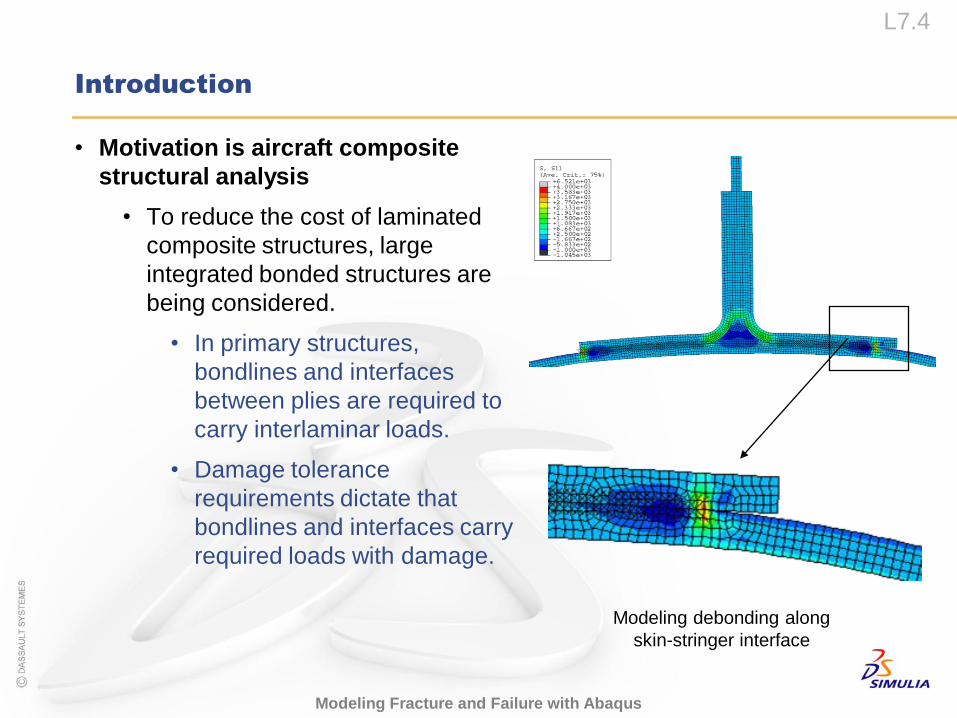
• Motivation is aircraft composite
structural analysis
• To reduce the cost of laminated
composite structures, large
integrated bonded structures are
being considered.
• In primary structures,
bondlines and interfaces
between plies are required to
carry interlaminar loads.
• Damage tolerance
requirements dictate that
bondlines and interfaces carry
required loads with damage.
Modeling debonding along
skin-stringer interface
L7.5
Modeling Fracture and Failure with Abaqus
Introduction
• Analysis requirements for composite damage
• Apply Linear Elastic Fracture Mechanics (LEFM) to bondlines and
interfaces
• 2D and 3D delaminations
• Propagation
• Mode separation
• Multiple cracks
• Non-linear behavior (e.g., postbuckling)
• Composite structure
• Practical (CPU time, minimum set of models)
L7.6
Modeling Fracture and Failure with Abaqus
Introduction
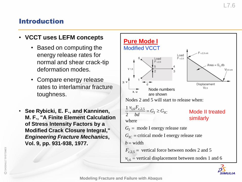
• VCCT uses LEFM concepts
• Based on computing the
energy release rates for
normal and shear crack-tip
deformation modes.
• Compare energy release
rates to interlaminar fracture
toughness.
• See Rybicki, E. F., and Kanninen,
M. F., "A Finite Element Calculation
of Stress Intensity Factors by a
Modified Crack Closure Integral,"
Engineering Fracture Mechanics,
Vol. 9, pp. 931-938, 1977.
1,6 ,2,5
,2,5
1,6
Nodes 2 and 5 will start to release when:
1
2
where
mode I energy release rate
critical mode I energy release rate
width
vertical force between nodes 2 and 5
vertical
vI IC
I
IC
v
v FG G
bd
G
G
b
F
v
displacement between nodes 1 and 6
Mode II treated
similarly
Node numbers
are shown
Pure Mode IModified VCCT
VCCT Criterion
L7.8
Modeling Fracture and Failure with Abaqus
VCCT Criterion
• The debond capability is used to perform the crack propagation analysis
for initially bonded crack surfaces.
• The crack propagation analysis allows for five types of fracture criteria:
• Critical stress criterion
• Crack opening displacement criterion
• Crack length vs. time criterion
• VCCT criterion
• Low-cycle fatigue criterion
• Defining case 4, “VCCT criterion,” is the subject of this lecture.
• The details of cases 1, 2, and 3 are not discussed here. Please
consult the Abaqus Analysis User’s Manual for more details.
• The details of case 5 will be discussed later in Lecture 8 “Low-cycle
Fatigue.”
1
2
3
4
5
L7.9
Modeling Fracture and Failure with Abaqus
VCCT Criterion
• When using VCCT to model crack propagation,
• you must:
• define contact pairs for potential crack surfaces;
• define initially bonded crack surfaces;
• activate the crack propagation capability; and
• specify the VCCT criterion.
• you also may:
• define spatially varying critical energy release rates;
• use viscous regularization, contact stabilization, and/or automatic
stabilization to overcome convergence difficulties for unstable
propagating cracks;
• use a linear scaling technique to accelerate convergence for VCCT.
1
2
3
4
L7.10
Modeling Fracture and Failure with Abaqus
VCCT Criterion
• Defining the VCCT criterion is not currently supported in Abaqus/CAE.
• However, the VCCT plug-in is available and allows you to interactively
define the debond interface(s).
• The details of the VCCT plug-in will be discussed later in this
lecture.
• Downloaded from “VCCT plug-in utility,” SIMULIA Answer 3235.
L7.11
Modeling Fracture and Failure with Abaqus
VCCT Criterion
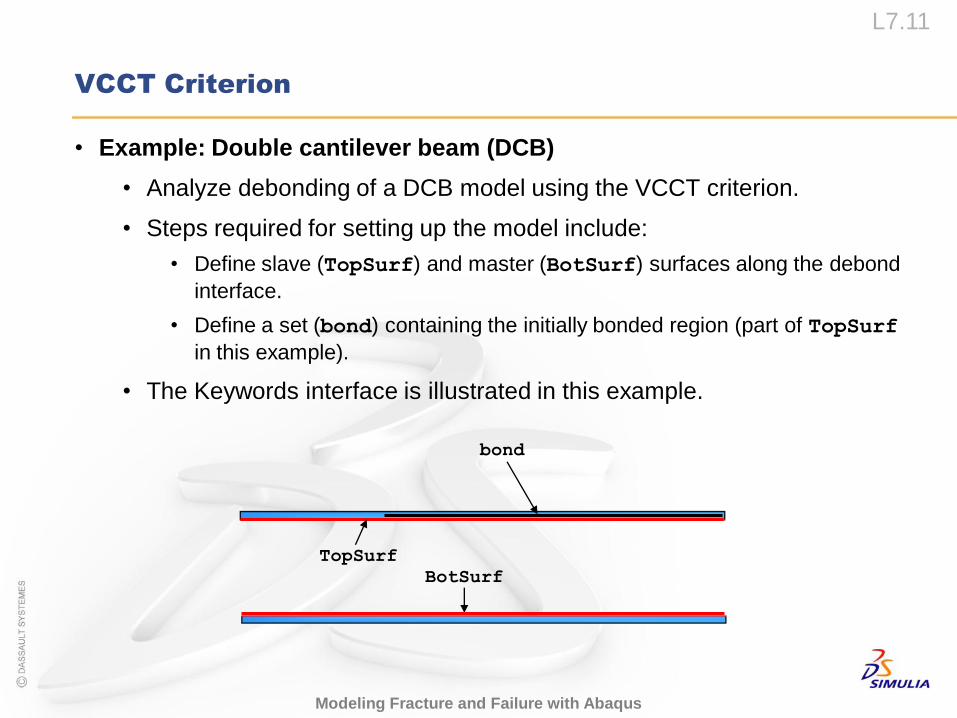
• Example: Double cantilever beam (DCB)
• Analyze debonding of a DCB model using the VCCT criterion.
• Steps required for setting up the model include:
• Define slave (TopSurf) and master (BotSurf) surfaces along the debond
interface.
• Define a set (bond) containing the initially bonded region (part of TopSurf
in this example).
• The Keywords interface is illustrated in this example.
BotSurf
TopSurf
bond
L7.12
Modeling Fracture and Failure with Abaqus
VCCT Criterion
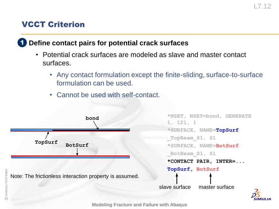
• Define contact pairs for potential crack surfaces
• Potential crack surfaces are modeled as slave and master contact
surfaces.
• Any contact formulation except the finite-sliding, surface-to-surface
formulation can be used.
• Cannot be used with self-contact.
1
*NSET, NSET=bond, GENERATE
1, 121, 1
*SURFACE, NAME=TopSurf
_TopBeam_S1, S1
*SURFACE, NAME=BotSurf
_BotBeam_S1, S1
*CONTACT PAIR, INTER=...
TopSurf, BotSurf
slave surface master surface
Note: The frictionless interaction property is assumed.
BotSurfTopSurf
bond
L7.13
Modeling Fracture and Failure with Abaqus
VCCT Criterion
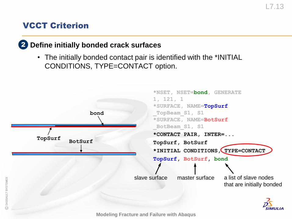
• Define initially bonded crack surfaces
• The initially bonded contact pair is identified with the *INITIAL
CONDITIONS, TYPE=CONTACT option.
BotSurfTopSurf
bond
*NSET, NSET=bond, GENERATE
1, 121, 1
*SURFACE, NAME=TopSurf
_TopBeam_S1, S1
*SURFACE, NAME=BotSurf
_BotBeam_S1, S1
*CONTACT PAIR, INTER=...
TopSurf, BotSurf
*INITIAL CONDITIONS, TYPE=CONTACT
TopSurf, BotSurf, bond
slave surface master surface a list of slave nodes
that are initially bonded
2
L7.14
Modeling Fracture and Failure with Abaqus
VCCT Criterion
• The unbonded portion of the slave surface will behave as a regular
contact surface.
• If the node set that includes the initially bonded slave nodes is not
specified, the initial contact condition will apply to the entire contact pair.
• In this case, no crack tips can be identified, and the bonded
surfaces cannot separate.
• For the VCCT criterion, the initially bonded nodes are bonded in all
directions.
L7.15
Modeling Fracture and Failure with Abaqus
VCCT Criterion
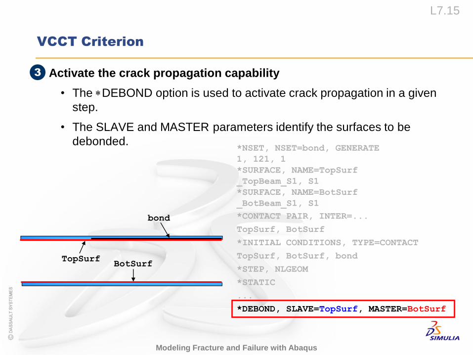
• Activate the crack propagation capability
• The DEBOND option is used to activate crack propagation in a given
step.
• The SLAVE and MASTER parameters identify the surfaces to be
debonded.
BotSurfTopSurf
bond
*NSET, NSET=bond, GENERATE
1, 121, 1
*SURFACE, NAME=TopSurf
_TopBeam_S1, S1
*SURFACE, NAME=BotSurf
_BotBeam_S1, S1
*CONTACT PAIR, INTER=...
TopSurf, BotSurf
*INITIAL CONDITIONS, TYPE=CONTACT
TopSurf, BotSurf, bond
*STEP, NLGEOM
*STATIC
...
*DEBOND, SLAVE=TopSurf, MASTER=BotSurf
3
L7.16
Modeling Fracture and Failure with Abaqus
VCCT Criterion
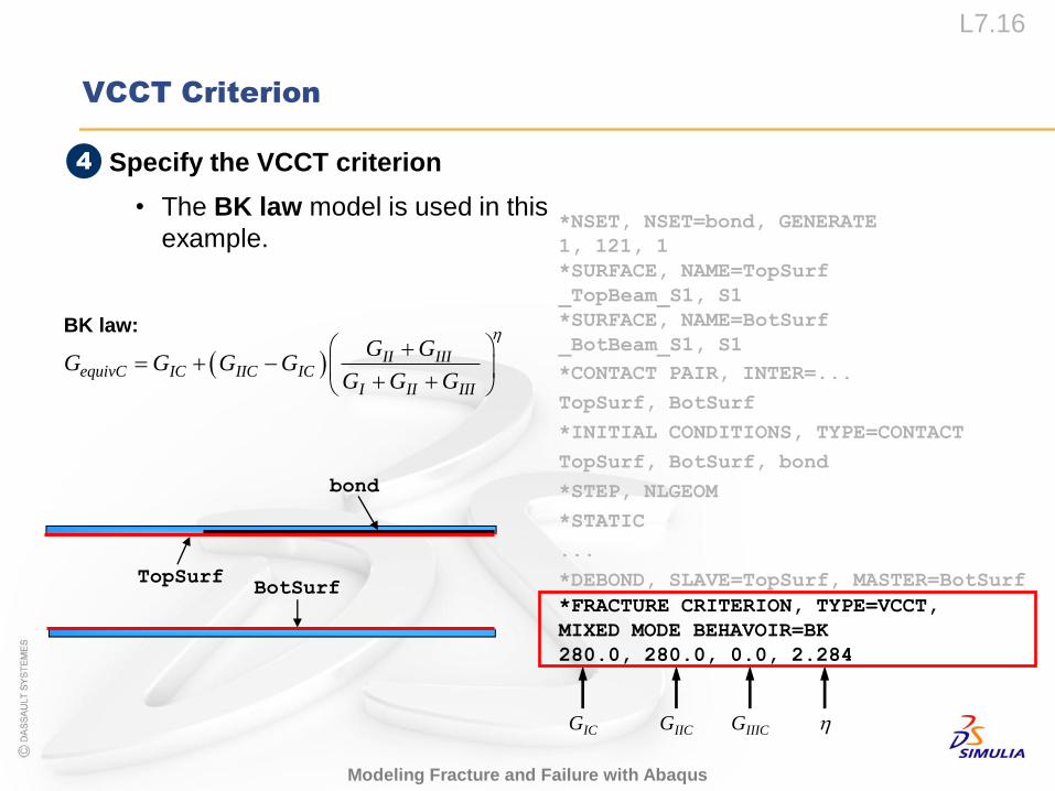
• Specify the VCCT criterion
• The BK law model is used in this
example. *NSET, NSET=bond, GENERATE
1, 121, 1
*SURFACE, NAME=TopSurf
_TopBeam_S1, S1
*SURFACE, NAME=BotSurf
_BotBeam_S1, S1
*CONTACT PAIR, INTER=...
TopSurf, BotSurf
*INITIAL CONDITIONS, TYPE=CONTACT
TopSurf, BotSurf, bond
*STEP, NLGEOM
*STATIC
...
*DEBOND, SLAVE=TopSurf, MASTER=BotSurf
*FRACTURE CRITERION, TYPE=VCCT,
MIXED MODE BEHAVOIR=BK
280.0, 280.0, 0.0, 2.284
GIC GIIC GIIIC
II IIIequivC IC IIC IC
I II III
G GG G G G
G G G
BotSurfTopSurf
bond
BK law:
4
L7.17
Modeling Fracture and Failure with Abaqus
VCCT Criterion
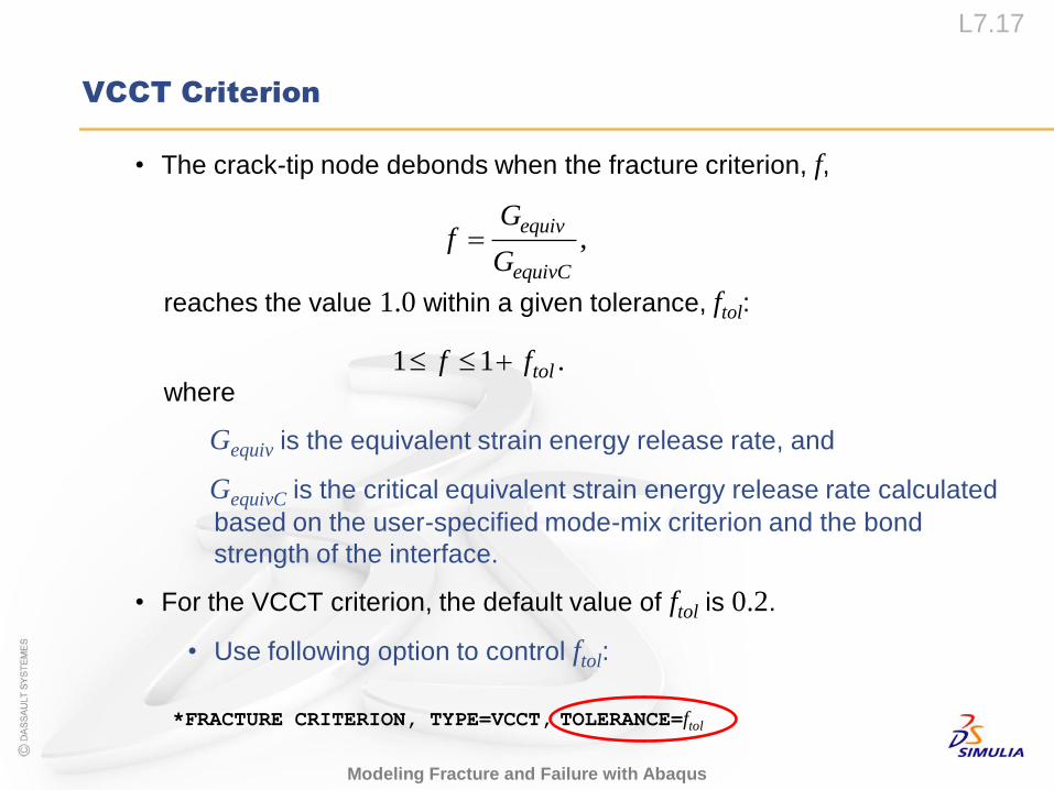
• The crack-tip node debonds when the fracture criterion, f,
reaches the value 1.0 within a given tolerance, ftol:
where
Gequiv is the equivalent strain energy release rate, and
GequivC is the critical equivalent strain energy release rate calculated
based on the user-specified mode-mix criterion and the bond
strength of the interface.
• For the VCCT criterion, the default value of ftol is 0.2.
• Use following option to control ftol:
,equiv
equivC
Gf
G
*FRACTURE CRITERION, TYPE=VCCT, TOLERANCE=ftol
1 1 .tolf f
L7.18
Modeling Fracture and Failure with Abaqus
VCCT Criterion
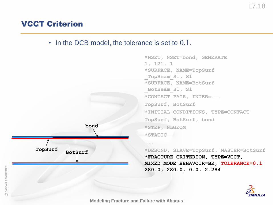
• In the DCB model, the tolerance is set to 0.1.
*NSET, NSET=bond, GENERATE
1, 121, 1
*SURFACE, NAME=TopSurf
_TopBeam_S1, S1
*SURFACE, NAME=BotSurf
_BotBeam_S1, S1
*CONTACT PAIR, INTER=...
TopSurf, BotSurf
*INITIAL CONDITIONS, TYPE=CONTACT
TopSurf, BotSurf, bond
*STEP, NLGEOM
*STATIC
...
*DEBOND, SLAVE=TopSurf, MASTER=BotSurf
*FRACTURE CRITERION, TYPE=VCCT,
MIXED MODE BEHAVOIR=BK, TOLERANCE=0.1
280.0, 280.0, 0.0, 2.284
BotSurfTopSurf
bond
L7.19
Modeling Fracture and Failure with Abaqus
VCCT Criterion
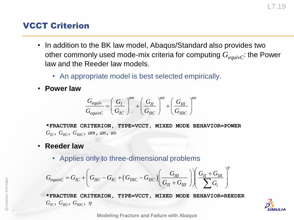
• In addition to the BK law model, Abaqus/Standard also provides two
other commonly used mode-mix criteria for computing GequivC: the Power
law and the Reeder law models.
• An appropriate model is best selected empirically.
• Power law
• Reeder law
• Applies only to three-dimensional problems
am an ao
equiv I II III
equivC IC IIC IIIC
G G G G
G G G G
*FRACTURE CRITERION, TYPE=VCCT, MIXED MODE BEHAVIOR=POWER
GIC, GIIC, GIIIC, am, an, ao
*FRACTURE CRITERION, TYPE=VCCT, MIXED MODE BEHAVIOR=REEDER
GIC, GIIC, GIIIC,
III II IIIequivC IC IIC IC IIIC IIC
II III i
G G GG G G G G G
G G G
L7.20
Modeling Fracture and Failure with Abaqus
VCCT Criterion
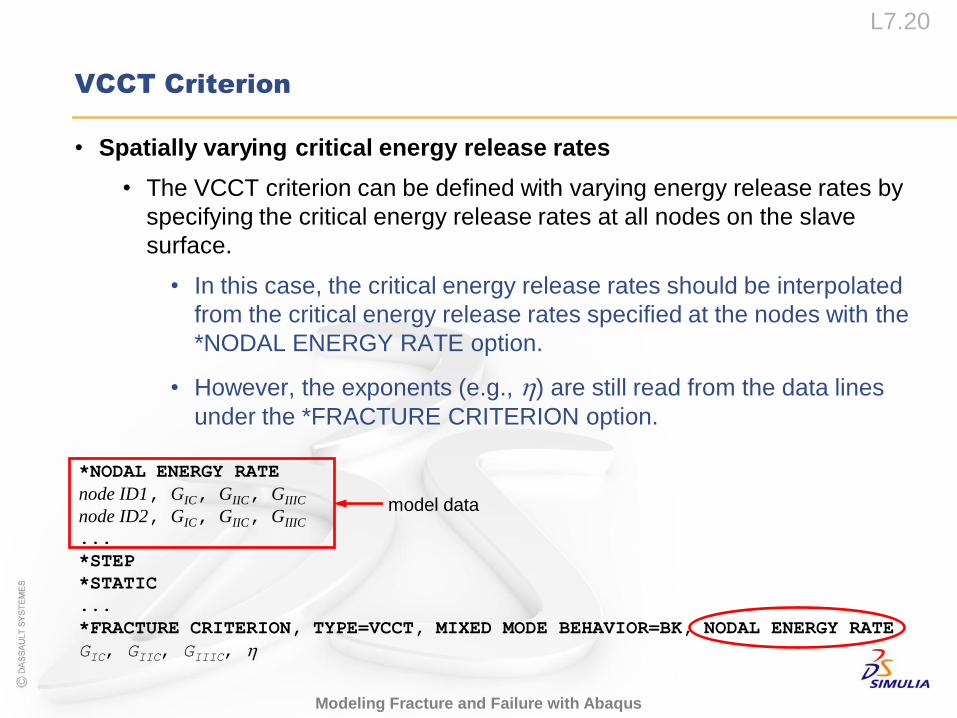
• Spatially varying critical energy release rates
• The VCCT criterion can be defined with varying energy release rates by
specifying the critical energy release rates at all nodes on the slave
surface.
• In this case, the critical energy release rates should be interpolated
from the critical energy release rates specified at the nodes with the
*NODAL ENERGY RATE option.
• However, the exponents (e.g., ) are still read from the data lines
under the *FRACTURE CRITERION option.
*NODAL ENERGY RATE
node ID1, GIC, GIIC, GIIIC
node ID2, GIC, GIIC, GIIIC
...
*STEP
*STATIC
...
*FRACTURE CRITERION, TYPE=VCCT, MIXED MODE BEHAVIOR=BK, NODAL ENERGY RATE
GIC, GIIC, GIIIC,
model data
L7.21
Modeling Fracture and Failure with Abaqus
VCCT Criterion
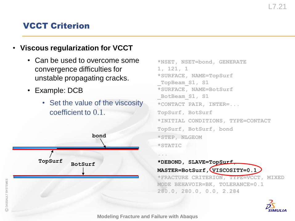
• Viscous regularization for VCCT
• Can be used to overcome some
convergence difficulties for
unstable propagating cracks.
• Example: DCB
• Set the value of the viscosity
coefficient to 0.1.
*NSET, NSET=bond, GENERATE
1, 121, 1
*SURFACE, NAME=TopSurf
_TopBeam_S1, S1
*SURFACE, NAME=BotSurf
_BotBeam_S1, S1
*CONTACT PAIR, INTER=...
TopSurf, BotSurf
*INITIAL CONDITIONS, TYPE=CONTACT
TopSurf, BotSurf, bond
*STEP, NLGEOM
*STATIC
...
*DEBOND, SLAVE=TopSurf,
MASTER=BotSurf, VISCOSITY=0.1
*FRACTURE CRITERION, TYPE=VCCT, MIXED
MODE BEHAVOIR=BK, TOLERANCE=0.1
280.0, 280.0, 0.0, 2.284
BotSurfTopSurf
bond
L7.22
Modeling Fracture and Failure with Abaqus
VCCT Criterion
• In addition, contact and automatic stabilization that are not specific to
VCCT can be also used to aid convergence.
• They are built into Abaqus/Standard and are compatible with VCCT.
• Note that the crack propagation behavior may be modified by the
damping forces.
• Therefore, monitor the damping energy (ALLVD or ALLSD) and
compare it with the total strain energy in the model (ALLSE) to
ensure that the results are reasonable in the presence of damping.
• ALLVD stores the damping energy generated from viscous
regularization.
• ALLSD stores the damping energy generated from contact
stabilization and automatic stabilization.
L7.23
Modeling Fracture and Failure with Abaqus
VCCT Criterion
• Linear scaling to accelerate convergence for VCCT
• Abaqus provides a linear scaling technique to quickly converge to the
critical load state. This reduces the solution time required to reach the
onset of crack growth.
• This technique works best for models in which the deformation is
nearly linear before the onset of crack growth.
• Once the first crack-tip node releases, the linear scaling calculations will
no longer be valid and the time increment will be set to the default value.
• Usage:
*CONTROLS, LINEAR SCALING
where is the coefficient of linear scaling.
• For details of linear scaling to accelerate convergence for VCCT, see
“Crack propagation analysis,” Section 11.4.3 of the Abaqus Analysis
User’s Manual.
L7.24
Modeling Fracture and Failure with Abaqus
VCCT Criterion
• Tips for using the VCCT criterion
• Crack propagation problems using the VCCT criterion are numerically
challenging.
• To help you create a successful model, several tips for using the VCCT
criterion are provided:
• The master debonding surfaces must be continuous.
• The tie MPCs should NOT be used for the slave debonding surface
to avoid overconstraints.
• A small clearance between the debonding surfaces can be specified
to eliminate unnecessary severe discontinuity iterations during
incrementation as the crack begins to progress.
……
• Note: More tips are provided in “Crack propagation analysis,” Section
11.4.3 of the Abaqus Analysis User’s Manual.
Output
L7.26
Modeling Fracture and Failure with Abaqus
Output
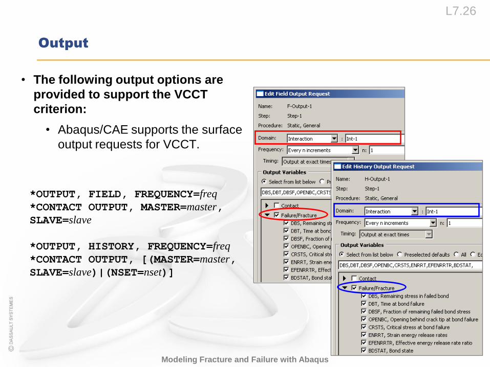
• The following output options are
provided to support the VCCT
criterion:
• Abaqus/CAE supports the surface
output requests for VCCT.
*OUTPUT, FIELD, FREQUENCY=freq
*CONTACT OUTPUT, MASTER=master,
SLAVE=slave
*OUTPUT, HISTORY, FREQUENCY=freq
*CONTACT OUTPUT, [(MASTER=master,
SLAVE=slave)|(NSET=nset)]
L7.27
Modeling Fracture and Failure with Abaqus
Output
• The following bond failure quantities can be requested as surface output:
DBT The time when bond failure occurred
DBSF Fraction of stress at bond failure that still remains
DBS Stress in the failed bond that remains
OPENBC Relative displacement behind crack.
CRSTS Critical stress at failure.
ENRRT Strain energy release rate.
EFENRRTR Effective energy release rate ratio.
BDSTAT Bond state (=1.0 if bonded, 0.0 if unbonded)
• All of the above variables can be visualized in Abaqus/Viewer.
• The initial contact status of all of the slave nodes is printed in the data (.dat) file.
L7.28
Modeling Fracture and Failure with Abaqus
Output
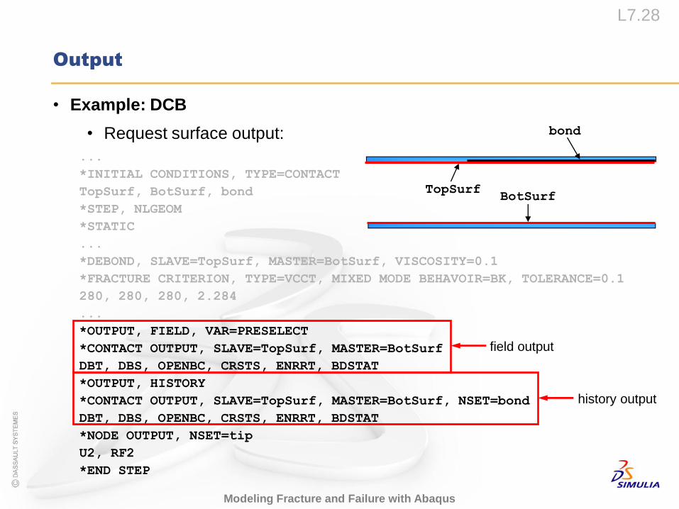
• Example: DCB
• Request surface output:
BotSurfTopSurf
bond
...
*INITIAL CONDITIONS, TYPE=CONTACT
TopSurf, BotSurf, bond
*STEP, NLGEOM
*STATIC
...
*DEBOND, SLAVE=TopSurf, MASTER=BotSurf, VISCOSITY=0.1
*FRACTURE CRITERION, TYPE=VCCT, MIXED MODE BEHAVOIR=BK, TOLERANCE=0.1
280, 280, 280, 2.284
...
*OUTPUT, FIELD, VAR=PRESELECT
*CONTACT OUTPUT, SLAVE=TopSurf, MASTER=BotSurf
DBT, DBS, OPENBC, CRSTS, ENRRT, BDSTAT
*OUTPUT, HISTORY
*CONTACT OUTPUT, SLAVE=TopSurf, MASTER=BotSurf, NSET=bond
DBT, DBS, OPENBC, CRSTS, ENRRT, BDSTAT
*NODE OUTPUT, NSET=tip
U2, RF2
*END STEP
field output
history output
L7.29
Modeling Fracture and Failure with Abaqus
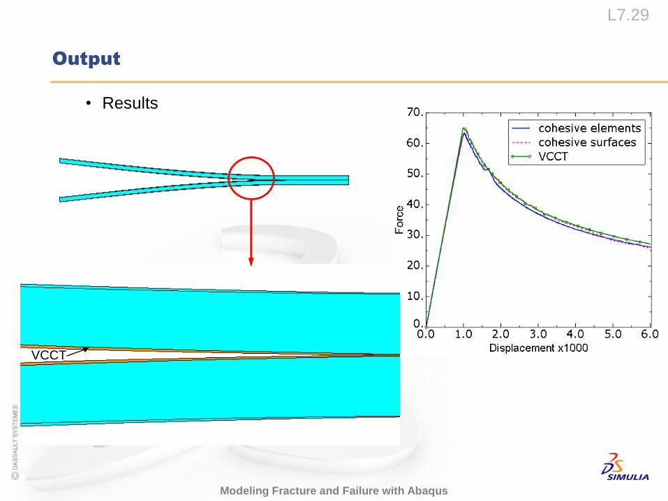
Output
• Results
VCCT
VCCT Plug-in
L7.31
Modeling Fracture and Failure with Abaqus
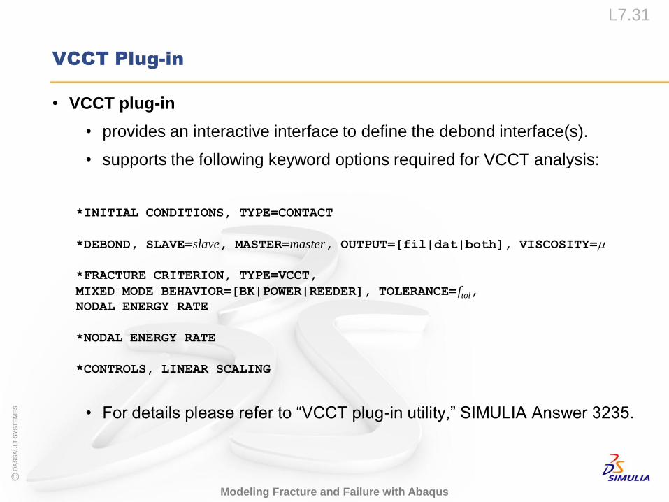
VCCT Plug-in
• VCCT plug-in
• provides an interactive interface to define the debond interface(s).
• supports the following keyword options required for VCCT analysis:
• For details please refer to “VCCT plug-in utility,” SIMULIA Answer 3235.
*INITIAL CONDITIONS, TYPE=CONTACT
*DEBOND, SLAVE=slave, MASTER=master, OUTPUT=[fil|dat|both], VISCOSITY=
*FRACTURE CRITERION, TYPE=VCCT,
MIXED MODE BEHAVIOR=[BK|POWER|REEDER], TOLERANCE=ftol,
NODAL ENERGY RATE
*NODAL ENERGY RATE
*CONTROLS, LINEAR SCALING
L7.32
Modeling Fracture and Failure with Abaqus
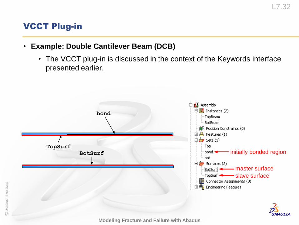
VCCT Plug-in
• Example: Double Cantilever Beam (DCB)
• The VCCT plug-in is discussed in the context of the Keywords interface
presented earlier.
BotSurf
TopSurf
bond
slave surface
master surface
initially bonded region
L7.33
Modeling Fracture and Failure with Abaqus
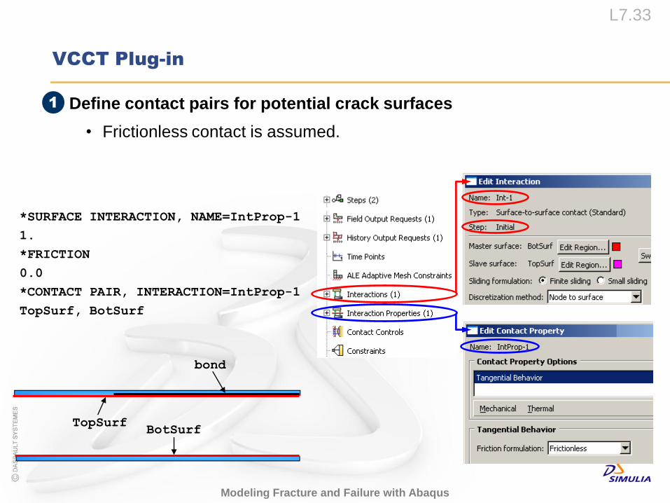
VCCT Plug-in
• Define contact pairs for potential crack surfaces
• Frictionless contact is assumed.
*SURFACE INTERACTION, NAME=IntProp-1
1.
*FRICTION
0.0
*CONTACT PAIR, INTERACTION=IntProp-1
TopSurf, BotSurf
BotSurfTopSurf
bond
1
L7.34
Modeling Fracture and Failure with Abaqus
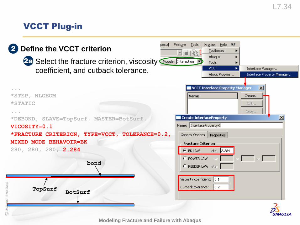
VCCT Plug-in
• Define the VCCT criterion
• Select the fracture criterion, viscosity
coefficient, and cutback tolerance.
...
*STEP, NLGEOM
*STATIC
...
*DEBOND, SLAVE=TopSurf, MASTER=BotSurf,
VICOSITY=0.1
*FRACTURE CRITERION, TYPE=VCCT, TOLERANCE=0.2,
MIXED MODE BEHAVOIR=BK
280, 280, 280, 2.284
2
2a
BotSurfTopSurf
bond
L7.35
Modeling Fracture and Failure with Abaqus
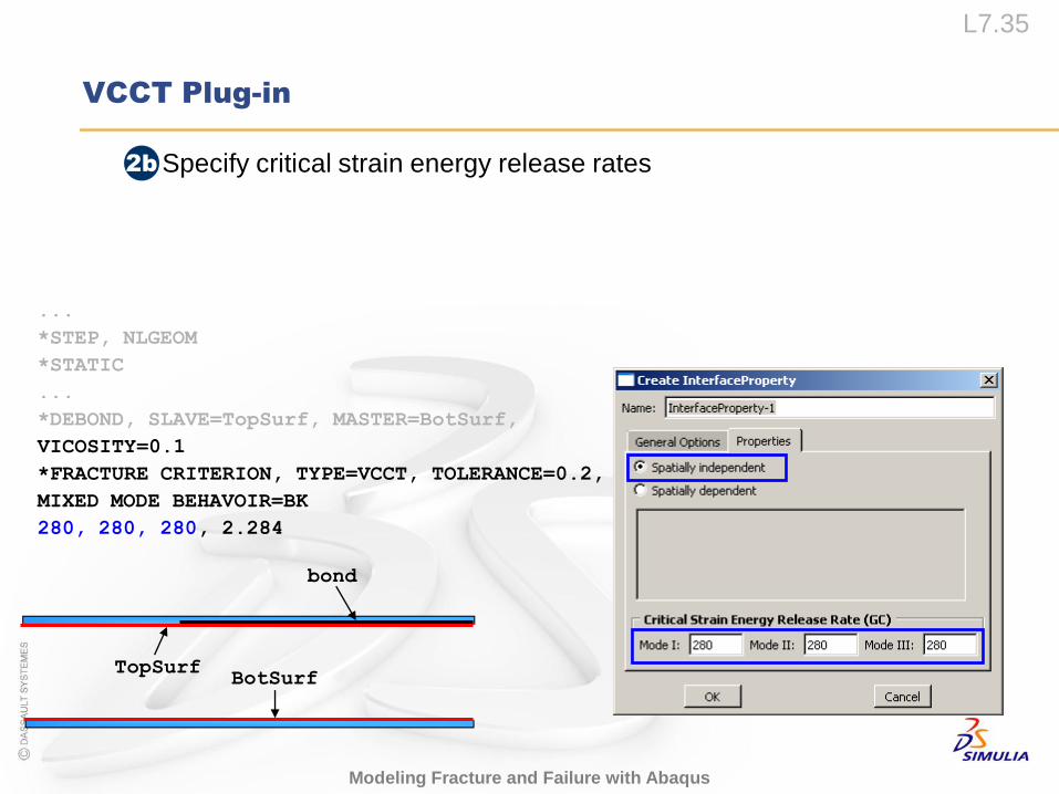
VCCT Plug-in
• Specify critical strain energy release rates2b
BotSurfTopSurf
bond
...
*STEP, NLGEOM
*STATIC
...
*DEBOND, SLAVE=TopSurf, MASTER=BotSurf,
VICOSITY=0.1
*FRACTURE CRITERION, TYPE=VCCT, TOLERANCE=0.2,
MIXED MODE BEHAVOIR=BK
280, 280, 280, 2.284
L7.36
Modeling Fracture and Failure with Abaqus
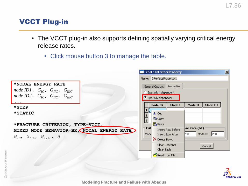
VCCT Plug-in
• The VCCT plug-in also supports defining spatially varying critical energy
release rates.
• Click mouse button 3 to manage the table.
*NODAL ENERGY RATE
node ID1, GIC, GIIC, GIIIC
node ID2, GIC, GIIC, GIIIC
...
*STEP
*STATIC
...
*FRACTURE CRITERION, TYPE=VCCT,
MIXED MODE BEHAVIOR=BK, NODAL ENERGY RATE
GIC, GIIC, GIIIC,
L7.37
Modeling Fracture and Failure with Abaqus
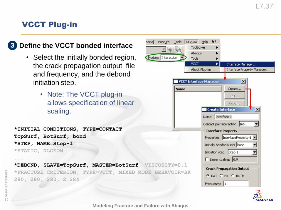
VCCT Plug-in
• Define the VCCT bonded interface
• Select the initially bonded region,
the crack propagation output file
and frequency, and the debond
initiation step.
• Note: The VCCT plug-in
allows specification of linear
scaling.
3
*INITIAL CONDITIONS, TYPE=CONTACT
TopSurf, BotSurf, bond
*STEP, NAME=Step-1
*STATIC, NLGEOM
...
*DEBOND, SLAVE=TopSurf, MASTER=BotSurf, VISCOSITY=0.1
*FRACTURE CRITERION, TYPE=VCCT, MIXED MODE BEHAVOIR=BK
280, 280, 280, 2.284
L7.38
Modeling Fracture and Failure with Abaqus
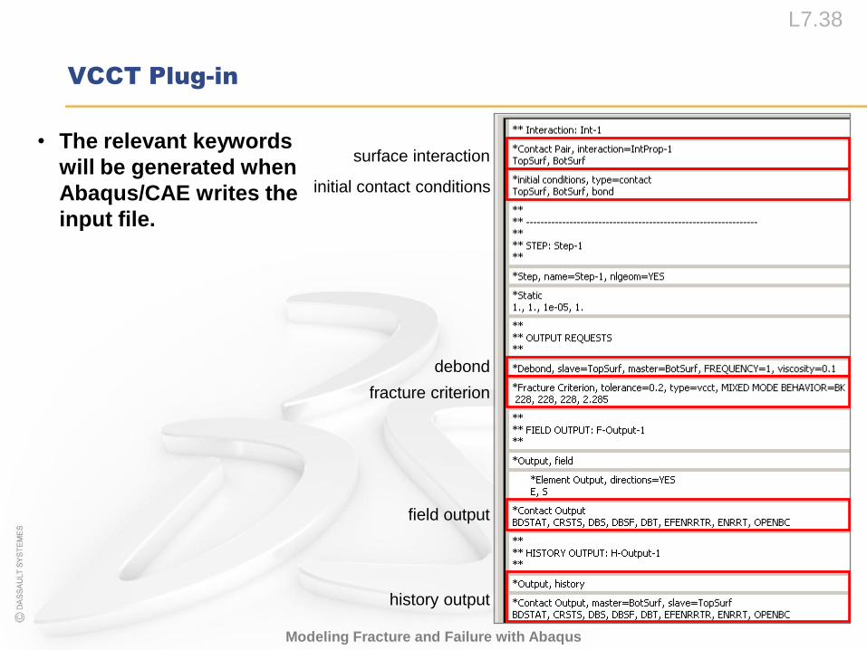
VCCT Plug-in
• The relevant keywords
will be generated when
Abaqus/CAE writes the
input file.
debond
field output
surface interaction
initial contact conditions
fracture criterion
history output
Comparison with Cohesive Behavior
L7.40
Modeling Fracture and Failure with Abaqus
Comparison with Cohesive Behavior
• VCCT and cohesive behavior are very similar in their application and
formulation.
• Both theories
• are used to model interfacial shearing and delamination crack
propagation and failure,
• use an elastic damage constitutive theory to model the
material's response once damage has initiated, and
• dissipate the same amount of fracture energy between damage
initiation and complete failure.
L7.41
Modeling Fracture and Failure with Abaqus
Comparison with Cohesive Behavior
• The fundamental difference between VCCT and cohesive behavior is in
the way crack propagation is predicted.
• In VCCT an existing flaw is assumed.
• VCCT is appropriate for brittle crack propagation problems.
• However, cohesive behavior can model damage initiation.
• Damage initiation in cohesive behavior is based strictly on the
predefined ultimate (normal and/or shear) stress/strain limit.
• Cohesive behavior can be used for both brittle and ductile crack
propagation problems.
L7.42
Modeling Fracture and Failure with Abaqus
Comparison with Cohesive Behavior
• VCCT may be viewed as more fundamentally based on fracture
mechanics.
• The damage initiation and damage evolution are both based on
fracture energy, whereas cohesive behavior use the fracture energy
only during damage evolution.
• Applicability of VCCT is limited to “self-similar” crack propagation
analyses.
• This implies a steady-state running crack.
• Difficult to reproduce in practice.
L7.43
Modeling Fracture and Failure with Abaqus
Comparison with Cohesive Behavior
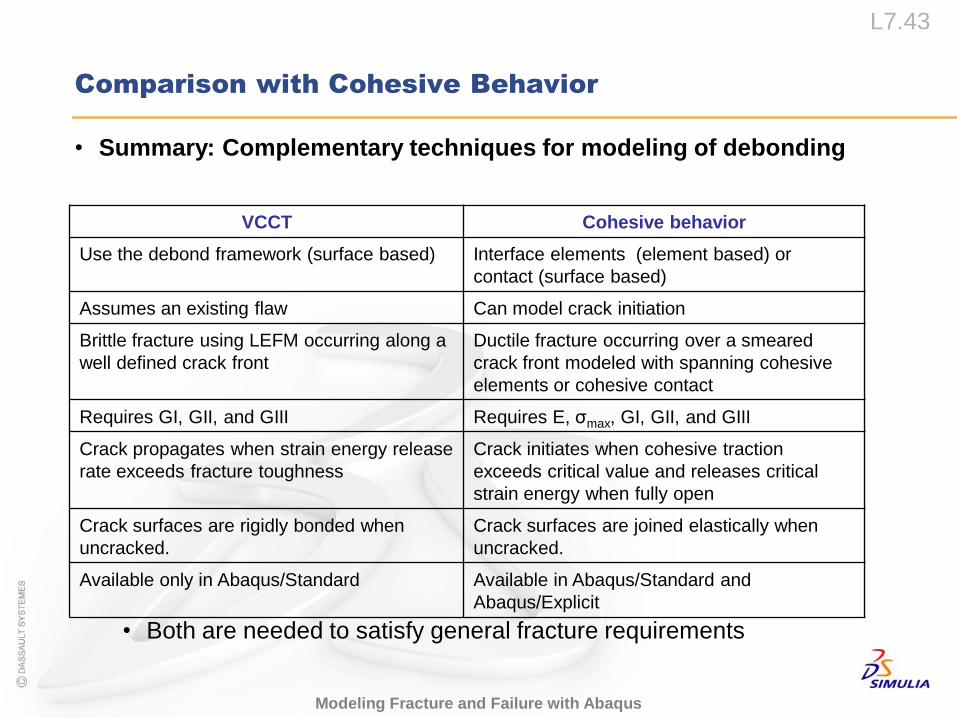
• Summary: Complementary techniques for modeling of debonding
• Both are needed to satisfy general fracture requirements
VCCT Cohesive behavior
Use the debond framework (surface based) Interface elements (element based) or
contact (surface based)
Assumes an existing flaw Can model crack initiation
Brittle fracture using LEFM occurring along a
well defined crack front
Ductile fracture occurring over a smeared
crack front modeled with spanning cohesive
elements or cohesive contact
Requires GI, GII, and GIII Requires E, σmax, GI, GII, and GIII
Crack propagates when strain energy release
rate exceeds fracture toughness
Crack initiates when cohesive traction
exceeds critical value and releases critical
strain energy when fully open
Crack surfaces are rigidly bonded when
uncracked.
Crack surfaces are joined elastically when
uncracked.
Available only in Abaqus/Standard Available in Abaqus/Standard and
Abaqus/Explicit
Examples
L7.45
Modeling Fracture and Failure with Abaqus
Examples
• Verification problems
• DCB
• SLB
• ENF
• Alfano-Crisfield
• Alfano, G., and M. A. Crisfield, “Finite Element Interface Models for
the Delamination Analysis of Laminated Composites: Mechanical
and Computational Issues,” International Journal for Numerical
Methods in Engineering, vol. 50, pp. 1701–1736, 2001.
• Also available as Abaqus Benchmark Problem 2.7.1 with cohesive
elements
• NASA Panel
• Reeder, J.R., Song, K., Chunchu, P.B., and Ambur, D.R.,
“Postbuckling and Growth of Delaminations in Composite Plates
Subjected to Axial Compression,” AIAA 2002-1746.
L7.46
Modeling Fracture and Failure with Abaqus
Examples
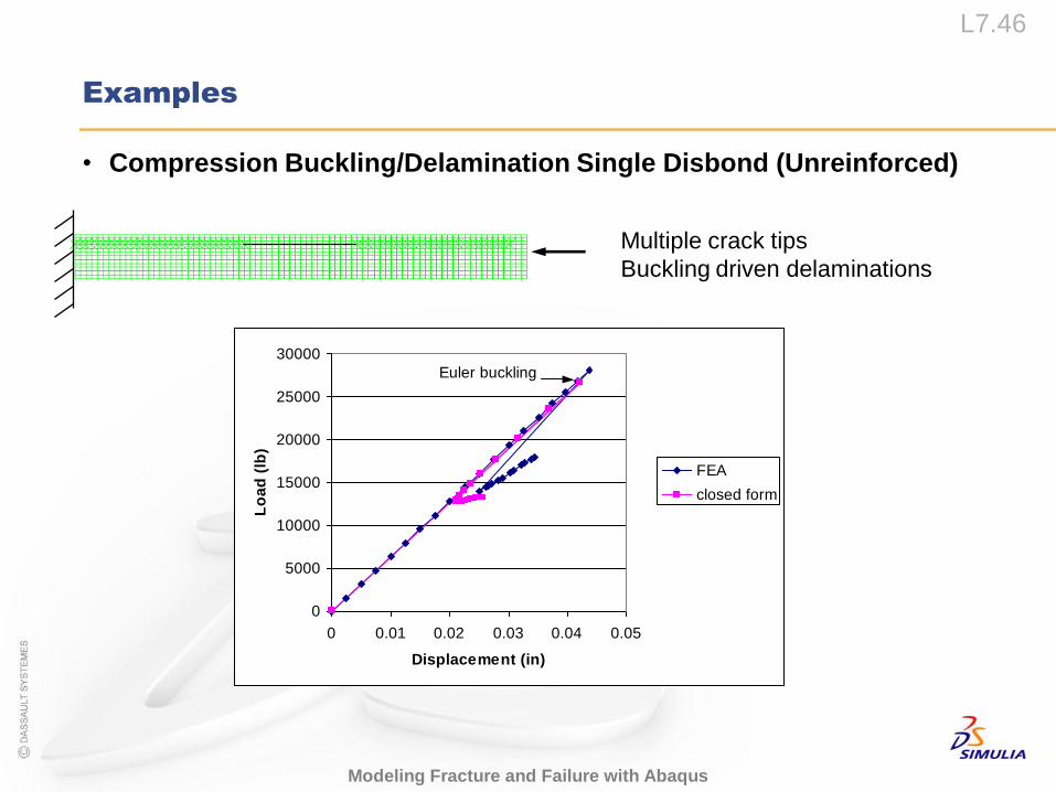
Euler buckling
0
5000
10000
15000
20000
25000
30000
0 0.01 0.02 0.03 0.04 0.05
Displacement (in)
Lo
ad
(lb
)
FEA
closed form
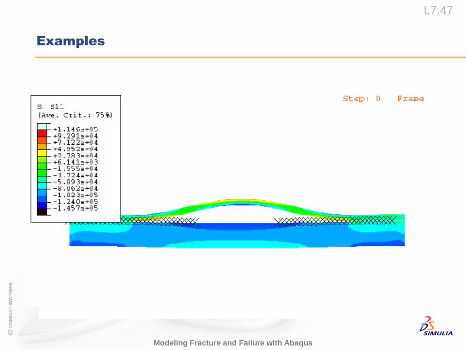
Multiple crack tips
Buckling driven delaminations
• Compression Buckling/Delamination Single Disbond (Unreinforced)
L7.47
Modeling Fracture and Failure with Abaqus
Examples
L7.48
Modeling Fracture and Failure with Abaqus
Examples
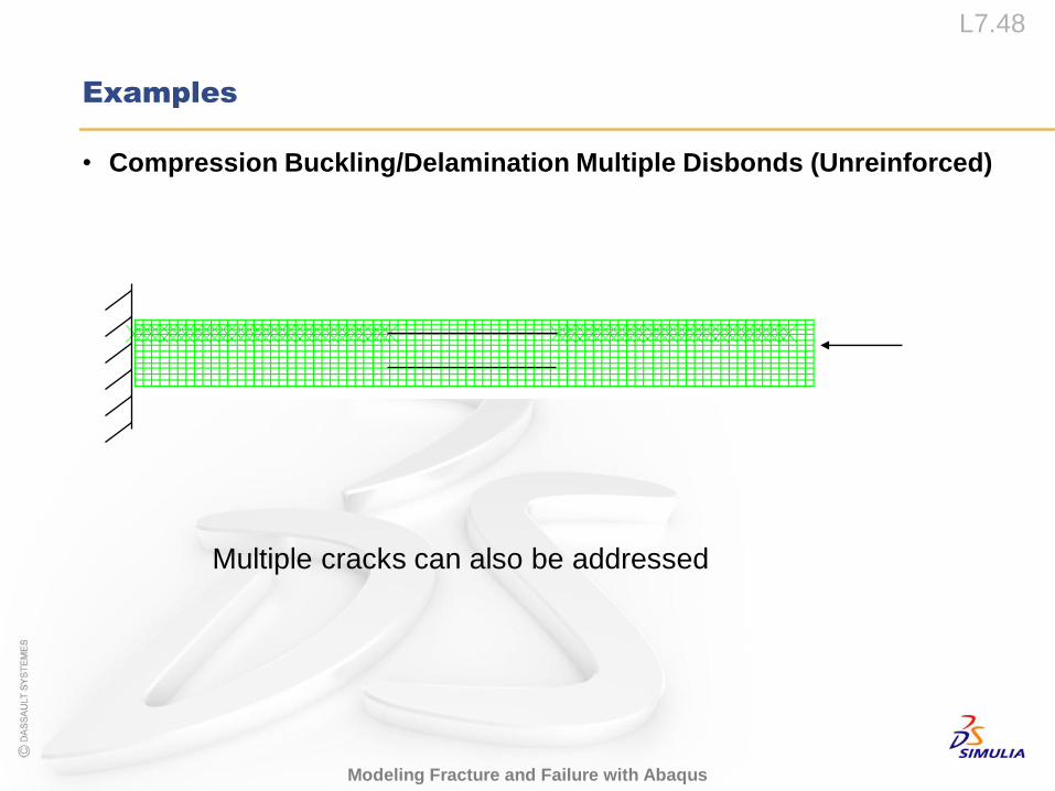
Multiple cracks can also be addressed
• Compression Buckling/Delamination Multiple Disbonds (Unreinforced)

L7.49
Modeling Fracture and Failure with Abaqus
Examples
L7.50
Modeling Fracture and Failure with Abaqus
Examples
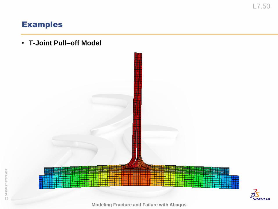
• T-Joint Pull–off Model
L7.51
Modeling Fracture and Failure with Abaqus
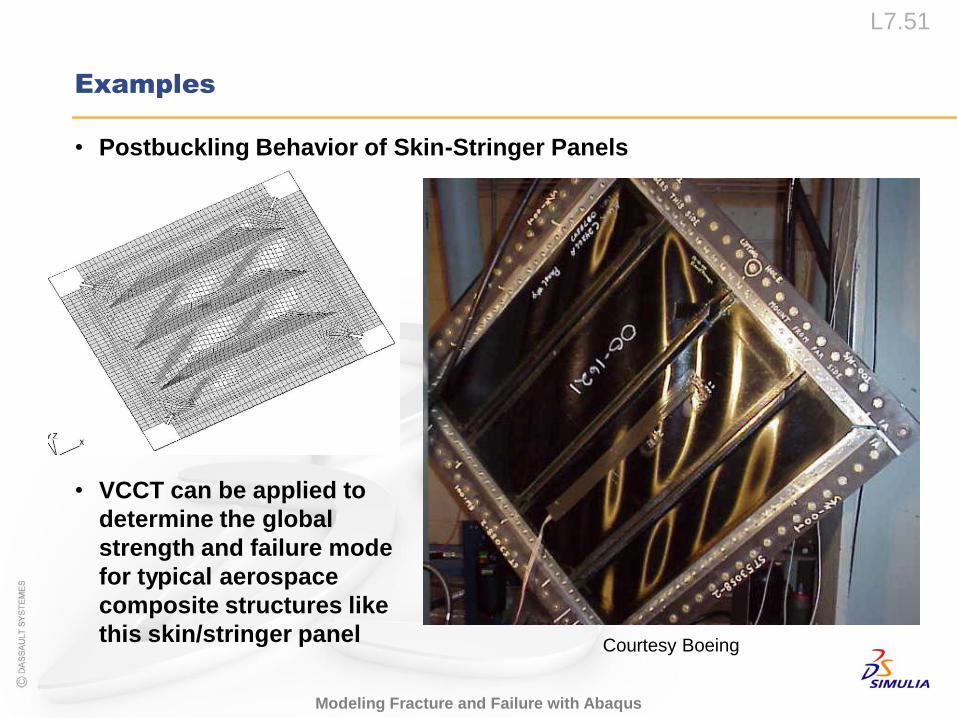
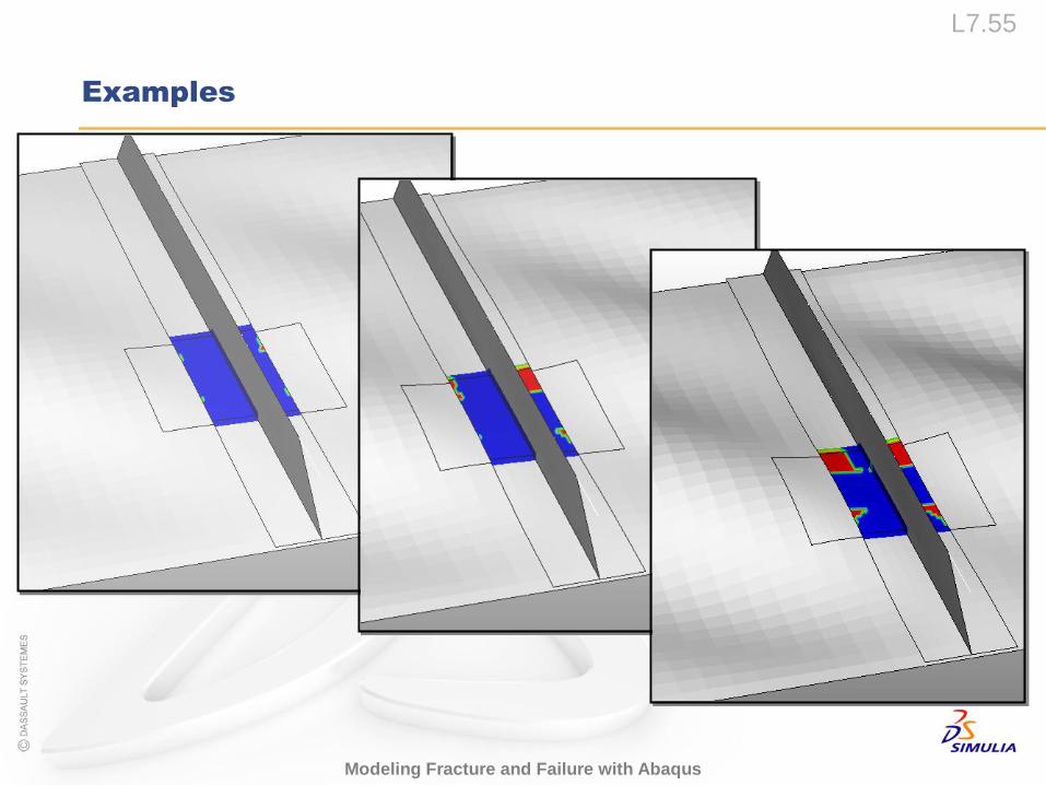
• Postbuckling Behavior of Skin-Stringer Panels
Examples
• VCCT can be applied to
determine the global
strength and failure mode
for typical aerospace
composite structures like
this skin/stringer panelCourtesy Boeing
L7.52
Modeling Fracture and Failure with Abaqus
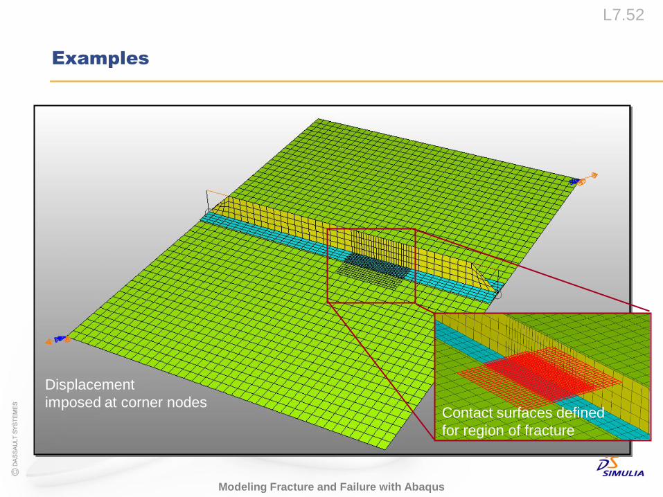
Examples
Displacement
imposed at corner nodesContact surfaces defined
for region of fracture
L7.53
Modeling Fracture and Failure with Abaqus
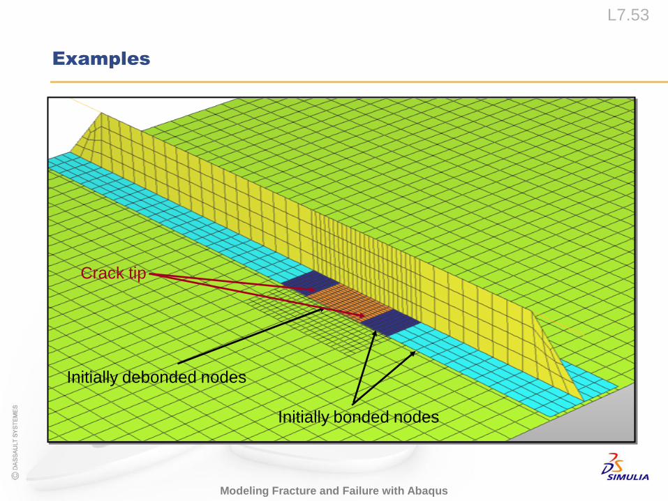
Examples
Initially bonded nodes
Initially debonded nodes
Crack tip
L7.54
Modeling Fracture and Failure with Abaqus
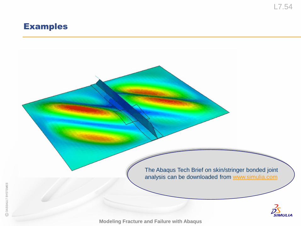
Examples
The Abaqus Tech Brief on skin/stringer bonded joint
analysis can be downloaded from www.simulia.com
L7.55
Modeling Fracture and Failure with Abaqus
Examples
Workshop 5
L7.57
Modeling Fracture and Failure with Abaqus
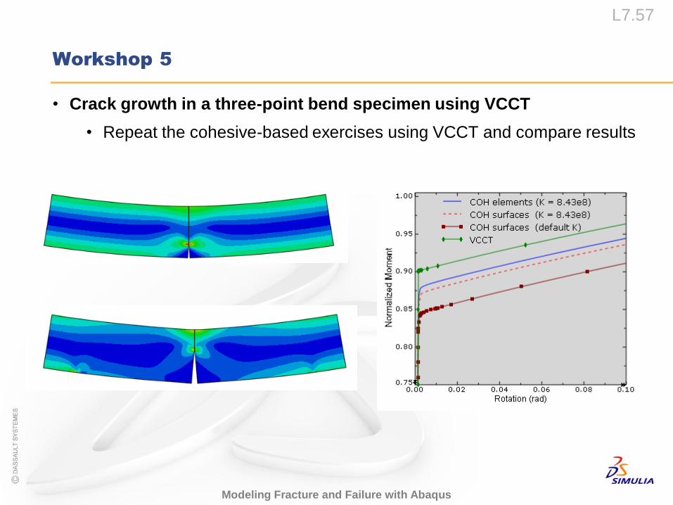
Workshop 5
• Crack growth in a three-point bend specimen using VCCT
• Repeat the cohesive-based exercises using VCCT and compare results


![Universit¨at Karlsruhe (TH) Institut f¨ur Baustatik · fracture mechanics approach is the virtual crack closure technique (VCCT) which has been proposed by Rybicki & Kanninen [2].](https://static.fdocuments.net/doc/165x107/605edf6b03689948ed0f84ed/universitat-karlsruhe-th-institut-fur-fracture-mechanics-approach-is-the-virtual.jpg)