Beams Session 15-22 Subject: S1014 / MECHANICS of MATERIALS Year: 2008.
Viridor Waste Management FICHTNER
S1014-0340-0011MPW Supporting info Rev3.doc
Print Date: 20 February 2009
ISSUE NUMBER 1 2 3
DATE 10/12/08 22/01/09 19/02/09
AUTHOR MPW MPW MPW
CHECKED SMO SMO SMO
Tit le Page
VIRIDOR WASTE MANAGEMENT
ARDLEY EFW PLANT
EP APPLICATION SUPPORTING INFORMATION
Viridor Waste Management FICHTNER
20/02/2009 Ardley EFW Plant - EP Applicat ion Supporting Information - 2 –
S1014-0340-0011MPW Support ing info Rev3.doc
TABLE OF CONTENTS
TABLE OF CONTENTS......................................................................................................................... 2
1 INTRODUCTION....................................................................................................................... 4
1.1 The Applicant....................................................................................................................... 4
1.2 The Site................................................................................................................................. 4
1.3 Summary of Proposed Operations ...................................................................................... 4 1.3.1 Overview ................................................................................................................................. 4 1.3.2 Raw Materials......................................................................................................................... 5 1.3.3 Combustion Process............................................................................................................... 6 1.3.4 Energy Recovery..................................................................................................................... 6 1.3.5 Gas Cleaning .......................................................................................................................... 7 1.3.6 Ancillary Operations .............................................................................................................. 7 1.3.7 Ash Handling .......................................................................................................................... 7 1.3.8 Liquid Effluent and Site Drainage......................................................................................... 8 1.3.9 Emissions Monitoring ............................................................................................................ 9
2 OTHER INFORMATION FOR APPLICATION FORM ................................................. 10
2.1 Raw materials..................................................................................................................... 10 2.1.1 Types and amounts of raw materials................................................................................... 10 2.1.2 Reagent Storage.................................................................................................................... 13 2.1.3 Raw Materials Selection ...................................................................................................... 14 2.1.4 Incoming Waste Management.............................................................................................. 17 2.1.5 Waste Minimisation Audit (Minimising the Use of Raw Materials) .................................. 21 2.1.6 Water Use ............................................................................................................................. 22
2.2 Emissions ........................................................................................................................... 24 2.2.1 Emissions to Air.................................................................................................................... 24 2.2.2 Emissions to water................................................................................................................ 24 2.2.3 Contaminated water ............................................................................................................. 25
2.3 Monitoring Methods .......................................................................................................... 26 2.3.1 Emissions Monitoring .......................................................................................................... 26 2.3.2 Environmental Monitoring (Beyond the Installation) ........................................................ 28 2.3.3 Monitoring of Process Variables......................................................................................... 28
2.4 Technology Selection ........................................................................................................ 29 2.4.1 Combustion Technology....................................................................................................... 29 2.4.2 Flue Gas Recirculation (FGR) ............................................................................................ 31 2.4.3 NOx Reduction System.......................................................................................................... 31 2.4.4 Acid Gas Abatement System................................................................................................. 35 2.4.5 Steam Condenser.................................................................................................................. 37 2.4.6 Bottom Ash Processing ........................................................................................................ 37
2.5 Specific Information required by the Waste Incineration Directive................................ 39
Viridor Waste Management FICHTNER
20/02/2009 Ardley EFW Plant - EP Applicat ion Supporting Information - 3 –
S1014-0340-0011MPW Support ing info Rev3.doc
2.5.1 Furnace Requirements ......................................................................................................... 39 2.5.2 Unavoidable Stoppages........................................................................................................ 42
2.6 Energy Efficiency .............................................................................................................. 45 2.6.1 General ................................................................................................................................. 45 2.6.2 Basic Energy Requirements ................................................................................................. 45 2.6.3 Further Energy Efficiency Requirements ............................................................................ 47
2.7 Waste Recovery and Disposal........................................................................................... 49 2.7.1 Introduction .......................................................................................................................... 49 2.7.2 Metals Separated from the Received MSW ......................................................................... 49 2.7.3 Bottom Ash............................................................................................................................ 49 2.7.4 Air Pollution Control Residues............................................................................................ 50 2.7.5 Bottom Ash Leachate............................................................................................................ 50
2.8 Management....................................................................................................................... 53 2.8.1 Introduction .......................................................................................................................... 53 2.8.2 Management Systems ........................................................................................................... 53 2.8.3 Personnel .............................................................................................................................. 54 2.8.4 Competence, Training and Awareness................................................................................ 54
2.9 Closure................................................................................................................................ 56 2.9.1 Introduction .......................................................................................................................... 56 2.9.2 General ................................................................................................................................. 56 2.9.3 Site Closure Plan.................................................................................................................. 56
3 WASTE INCINERATION QUESTIONS ............................................................................. 58
ANNEX 1 LOCATION PLAN AND SITE PLANS............................................................ 64
ANNEX 2 SITE CONDITION REPORT............................................................................. 65
ANNEX 3 NOISE ASSESSMENT......................................................................................... 66
ANNEX 4 ENVIRONMENTAL RISK ASSESSMENT .................................................... 67
ANNEX 5 AIR QUALITY ASSESSMENT.......................................................................... 68
ANNEX 6 HEAT PLAN .......................................................................................................... 69
Viridor Waste Management FICHTNER
20/02/2009 Ardley EFW Plant - EP Applicat ion Supporting Information - 4 –
S1014-0340-0011MPW Support ing info Rev3.doc
1 INTRODUCTION
Viridor Waste Management Ltd (Viridor) are intending to build an Energy from Waste (EfW) facility at their existing Ardley waste management facility. The plant would have the capacity to process 300,000 tonnes of residual Municipal Solid Waste (MSW) and Commercial and Industrial (C & I) waste per annum from Oxfordshire, and export 22.1 MW of electricity. This would be sufficient to provide power to around 22,000 people.
This document and its annexes contain the supporting information for Viridor’s application for an Environmental Permit (EP). They should be read in conjunction with the formal application form. In this section 1, we have provided an overview of the proposal installation. In section 2, we have provided further information in response to specific questions in the application form. In section 3, we have responded to the specific questions designed to demonstrate that the proposed installation would comply with the requirements of the Waste Incineration Directive.
1.1 The Applicant
Viridor Waste Management Limited (Viridor) is owned by the Pennon Group, a major PLC that is focused on the water and waste management industries. Viridor is a leading waste management company and operates 25 regional landfill sites, numerous recycling facilities and over 200 waste processing sites (including composting and Energy from Waste) throughout the UK.
1.2 The Site
The application site comprises 5.8 hectares and is situated on the existing Ardley Waste Management site, located close to junction 10 of the M40 in Oxfordshire (National Grid Reference E454 200 N225 900) as illustrated in the location plan in Annex 1.
The site lies 1 km south of the village of Ardley, 1.7 km north of Middleton Stoney and 1.2 km west of Bucknell. The settlement of Upper Heyford is located over 2km to the west, adjacent to the former airfield. The northern boundary of the site abuts the Banbury to High Wycombe railway line and the eastern boundary follows Gagle Brook and a public bridleway. The southern boundary of the site is also a public bridleway.
Access to the site is obtained from the B430, which abuts the western boundary of the site. The B430 leads north to junction 10 of the M40 via Ardley and south to the A34 towards Oxford.
1.3 Summary of Proposed Operations
1.3.1 Overview
The main purpose of the activities at the Installation will be to burn Municipal and Commercial and Industrial waste and to recover energy in the form of steam, which will be used to produce electricity for export to the National Grid and potentially supply heat to users nearby.
The Installation covers the site and the entire incineration plant including the incineration lines, waste reception, storage, on-site pre-treatment facilities, water, fuel and air supply systems, boiler, facilities for the treatment of exhaust gases, on-site facilities for treatment or storage of residues and waste water, stack, devices and systems for controlling incineration operations, recording and monitoring conditions.
Viridor Waste Management FICHTNER
20/02/2009 Ardley EFW Plant - EP Applicat ion Supporting Information - 5 –
S1014-0340-0011MPW Support ing info Rev3.doc
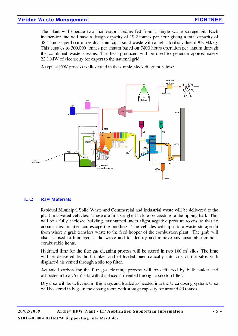
The plant will operate two incinerator streams fed from a single waste storage pit. Each incinerator line will have a design capacity of 19.2 tonnes per hour giving a total capacity of 38.4 tonnes per hour of residual municipal solid waste with a net calorific value of 9.2 MJ/kg. This equates to 300,000 tonnes per annum based on 7800 hours operation per annum through the combined waste streams. The heat produced will be used to generate approximately 22.1 MW of electricity for export to the national grid.
A typical EfW process is illustrated in the simple block diagram below:
1.3.2 Raw Materials
Residual Municipal Solid Waste and Commercial and Industrial waste will be delivered to the plant in covered vehicles. These are first weighed before proceeding to the tipping hall. This will be a fully enclosed building, maintained under slight negative pressure to ensure that no odours, dust or litter can escape the building. The vehicles will tip into a waste storage pit from where a grab transfers waste to the feed hopper of the combustion plant. The grab will also be used to homogenise the waste and to identify and remove any unsuitable or non-combustible items.
Hydrated lime for the flue gas cleaning process will be stored in two 100 m3 silos. The lime will be delivered by bulk tanker and offloaded pneumatically into one of the silos with displaced air vented through a silo top filter.
Activated carbon for the flue gas cleaning process will be delivered by bulk tanker and offloaded into a 75 m3 silo with displaced air vented through a silo top filter.
Dry urea will be delivered in Big Bags and loaded as needed into the Urea dosing system. Urea will be stored in bags in the dosing room with storage capacity for around 40 tonnes.
Viridor Waste Management FICHTNER
20/02/2009 Ardley EFW Plant - EP Applicat ion Supporting Information - 6 –
S1014-0340-0011MPW Support ing info Rev3.doc
Caustic soda for water treatment resin regeneration will be delivered by bulk tanker and offloaded into a 2 m3 tank in a bund within the demineralisation area.
Hydrochloric acid for water treatment resin regeneration will be delivered by bulk tanker and offloaded into a 5 m3 tank, vented through a scrubber, in a bund within the demineralisation area.
Various other water treatment chemicals will be delivered in appropriate containers and stored in bunded areas.
A 60 m3 bunded gas oil tank will provide oil for the combustion chamber burners and on-site vehicles. Any offloading spillages are retained in a gulley and surface water is drained via an oil separator to the main drainage system.
Various maintenance materials (oils, greases, insulants, antifreezes, welding and fire fighting gases etc.) will be stored in the appropriate manner.
1.3.3 Combustion Process
The hearth, a mechanical moving inclined reverse acting grate bar, ensures continuous mixing of the waste and hence promotes good combustion. As the waste enters the incinerator it passes through a drying zone, a combustion zone and a burnout zone. Primary combustion air is extracted from within the tipping hall and fed in below the waste through the grate bars to promote good combustion.
Secondary combustion air will be injected above the waste where it provides for good mixing and combustion control. Urea will be injected into the combustion chamber to react with the oxides of nitrogen, chemically reducing them to nitrogen and water.
Auxiliary low sulphur gasoil burners will be fitted for start-up sequencing and to maintain temperatures above 850°C for 2 seconds. The oxygen concentration and temperature are carefully controlled to ensure complete combustion and minimise dioxin emissions.
Bottom ash from the grate will be transported by the grate to the bottom of the hearth and into a water filled quench pit. A conveyor will then transport the wet ash through a magnetic separator to remove some of the ferrous metals to the discharge point in the bottom ash storage and treatment hall.
1.3.4 Energy Recovery
Hot gases from the waste combustion will pass through a series of heat exchangers and superheaters and finally through a two stage economiser. The first stage of the economiser would be used to preheat feedwater before it is supplied to the boiler and the second stage would be used to heat up condensate and will ensure that the flue gas temperature is the optimum temperature for reaction with lime. The design of the boilers, following a computerised fluid dynamics assessment, is such that the flue gas temperature is quickly reduced through the critical temperature range to minimise the risk of dioxin reformation.
Steam generating boilers will be located at the exit of the flue gas from the main chamber. The steam will be fed to a steam turbine which will generate electricity. Water for steam generation will be taken from the public water supply and treated prior to use in the boilers. Steam will be condensed and recycled to the boiler.
There will be no need for cooling water as the steam will be condensed in an air cooled condenser which is capable of taking the full load from the boiler to ensure continuous operation of the EfW Plant.
Viridor Waste Management FICHTNER
20/02/2009 Ardley EFW Plant - EP Applicat ion Supporting Information - 7 –
S1014-0340-0011MPW Support ing info Rev3.doc
1.3.5 Gas Cleaning
Flue gases pass from the boiler to the gas cleaning equipment. The gas will enter a reaction duct where dry hydrated lime reacts with and neutralises the acid gases. Activated carbon will be injected into the duct preceding the bag filter to adsorb (primarily) dioxins, other volatile organic compounds (VOCs) and mercury. The lime injection rate will be controlled by upstream measurement of hydrogen chloride (HCl) thus optimising the efficiency of gas scrubbing and lime usage.
Nitrogen oxides (NOx) abatement will be achieved by the use of selective non-catalytic reduction (SNCR). The SNCR is based on the injection of urea into the furnace chambers.
Bag filters will be used to remove the fine ash plus excess and spent lime and carbon as the gases pass through the bag filter fabric. The build up of the latter two enhances the performance of the system. Reverse pulses of compressed air will be used to remove the accumulated particulate from the bags. These Air Pollution Control (APC) Residues will fall into a collection hopper and are then conveyed via a feeder screw to a storage silo or back into the flue gas via the recirculation system. The recirculation system allows the unreacted lime in the APC residue to be recycled back to the flue gas via a reactivation step for further contact with acid gases.
The cleaned gas will then discharge to atmosphere via an 82 metre high stack at an efflux velocity in excess of 15.65 m/s at design throughput.
1.3.6 Ancillary Operations
Demineralised water is required to compensate for boiler blowdown losses. A package demineralisation plant provides this water. The ion exchange resins are regenerated using sodium hydroxide and hydrochloric acid and the regeneration effluent is routed through a neutralisation tank to the settlement and treatment pit for reuse in the ash discharger.
Process water will be recirculated via a settlement and treatment pit designed to remove any ash from the bottom ash quenching process. Process water streams from the demineralisation plant and boiler blowdown etc are all routed to this pit for use as bottom ash quench water.
Water for fire fighting will be stored in tanks with a dedicated pumpset.
1.3.7 Ash Handling
The incinerator bottom ash and boiler ash will be collected and combined within the EfW building and conveyed to the incinerator bottom ash facility. The incinerator bottom ash (IBA) facility will allow for the pre-treatment storage, treatment, long term storage and sealed loading of the anticipated 75,600 tpa of IBA produced by the EfW facility.
At least quarterly sampling of the bottom ash will be carried out to ensure effective burn out is being achieved by testing for the total organic carbon in the residual ash.
Fly ash which is collected in the bag filter will already be combined with the flue gas treatment residues and will therefore be taken off site in sealed tankers for disposal at a hazardous landfill.
Viridor Waste Management FICHTNER
20/02/2009 Ardley EFW Plant - EP Applicat ion Supporting Information - 8 –
S1014-0340-0011MPW Support ing info Rev3.doc
1.3.7.1 Bottom ash Processing Facility
The bottom ash and boiler ash will be processed on a “campaign” basis by mobile plant as stock accumulates to produce a secondary aggregate for the construction industry. Processing involves mechanical treatment and maturation to produce stabilised aggregate of several different product grades.
The mechanical treatment is carried out under cover by mobile plant and first utilises magnetic overbelt and eddy current separators for removal of ferrous and non-ferrous metals respectively. The metals will be collected separately and sent off site for recycling. The ash is then sorted into several different size fractions by mechanical trommel screens. A small proportion of the ash is oversize and is removed from site for disposal by non-hazardous landfill. The remaining fractions are then transferred to the external stockpile areas for maturation. The equipment used in the mechanical treatment will be powered from the EfW plant electricity supply with an expected parasitic load of 0.15 MW.
The maturation process is required to stabilise the ash to ensure its leaching properties are acceptable for use as an aggregate product. Maturation requires exposure to air and water, which is achieved by stockpiling the classified material in the open air. Carbonation reactions utilise carbon dioxide in the air and reduce the pH of the ash whilst reducing the metal solubility. Rainwater is used to remove soluble metal salts, chlorides and sulphates. The maturation process lasts for several weeks and will take place in the external storage area enclosed within a continuous wall.
Leachate from the ash piles will be contained within the enclosed storage area and directed into a drainage system. The leachate will drain into a lagoon which provides settlement and storage before reuse on the ash piles. Lagoon water will be sprayed onto the ash to maintain the correct conditions for maturation and prevent fugitive emissions of dust.
Once processed, the aggregate will be stockpiled awaiting sale, within the two uncovered maturation areas on either side of the bottom ash processing plant.
1.3.8 Liquid Effluent and Site Drainage
All process water will be recycled within the EfW building.
The EfW building is designed with a sustainable drainage management scheme to contain process water within the building and ensure surface water is not contaminated. Potentially contaminated rainwater from the road, car park and other hardstanding will be contained by kerbs and collected by gullies before passing through an appropriately sized interceptor into the balancing pond. Rainwater from the roof will be collected in the balancing pond. Water from the balancing pond will be discharged in a controlled manner into Gagle Brook. The water quality can be tested within the interceptor or the discharge chamber. Contamination from the interceptors will be removed from site by tanker.
Surface water will also be collected in a small lagoon adjacent to the boiler hall for use in the bottom ash processing facility. The lagoon would be incorporated within the overall landscaping of the site. Leachate from the bottom ash processing facility will drain to this lagoon for reuse on the ash stockpiles. Any excess water from the lagoon will be sent to the EfW bottom ash quench if there is a demand for water, and the remainder will be transferred to the existing landfill leachate treatment plant by road tanker.
Viridor Waste Management FICHTNER
20/02/2009 Ardley EFW Plant - EP Applicat ion Supporting Information - 9 –
S1014-0340-0011MPW Support ing info Rev3.doc
1.3.9 Emissions Monitoring
Emissions from the stack will be continuously monitored for: particulate, carbon monoxide (CO), ammonia (NH3), sulphur dioxide (SO2), hydrogen chloride (HCl), hydrogen fluoride (HF), oxygen (O2), nitrogen oxides (NOx) and volatile organic compounds (VOC). In addition periodic sampling and measurement will be carried out for metals [cadmium (Cd), thallium (Tl), mercury (Hg), antimony (Sb), arsenic (As), lead (Pb), chromium (Cr), cobalt (Co), copper (Cu), manganese (Mn), nickel (Ni), vanadium (V)], dioxins and furans and dioxin like PCBs. Periodic measurements will be carried out four times in the first year and twice per year thereafter.
The Continuous Emission Monitoring (CEM) system will include backup capability consisting of two active CEMs with a third system in standby.
Viridor Waste Management FICHTNER
20/02/2009 Ardley EFW Plant - EP Applicat ion Supporting Information - 10 –
S1014-0340-0011MPW Support ing info Rev3.doc
2 OTHER INFORMATION FOR APPLICATION FORM
2.1 Raw materials
2.1.1 Types and amounts of raw materials
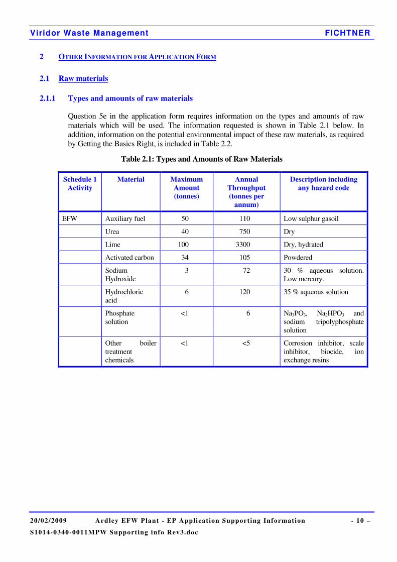
Question 5e in the application form requires information on the types and amounts of raw materials which will be used. The information requested is shown in Table 2.1 below. In addition, information on the potential environmental impact of these raw materials, as required by Getting the Basics Right, is included in Table 2.2.
Table 2.1: Types and Amounts of Raw Materials
Schedule 1 Activity
Material Maximum Amount (tonnes)
Annual Throughput (tonnes per
annum)
Description including any hazard code
EFW Auxiliary fuel 50 110 Low sulphur gasoil
Urea 40 750 Dry
Lime 100 3300 Dry, hydrated
Activated carbon 34 105 Powdered
Sodium Hydroxide
3 72 30 % aqueous solution. Low mercury.
Hydrochloric acid
6 120 35 % aqueous solution
Phosphate solution
<1 6 Na3PO3, Na2HPO3 and sodium tripolyphosphate solution
Other boiler treatment chemicals
<1 <5 Corrosion inhibitor, scale inhibitor, biocide, ion exchange resins
Viridor Waste Management FICHTNER
20/02/2009 Ardley EFW Plant - EP Applicat ion Supporting Information - 11 –
S1014-0340-0011MPW Support ing info Rev3.doc
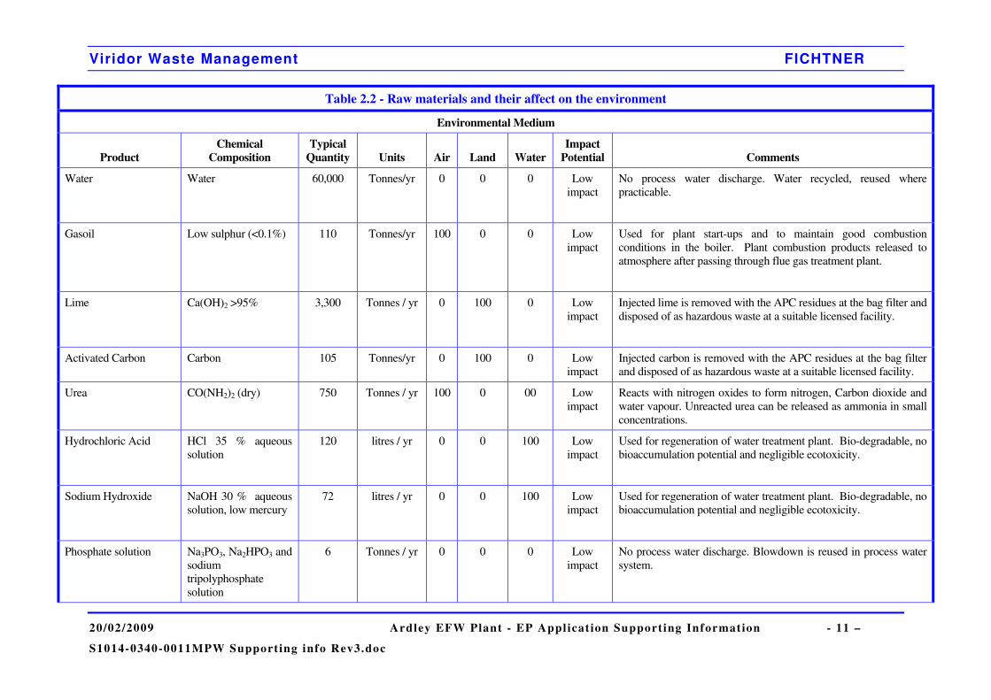
Table 2.2 - Raw materials and their affect on the environment
Environmental Medium
Product Chemical
Composition Typical
Quantity Units Air Land Water Impact
Potential Comments
Water Water 60,000 Tonnes/yr 0 0 0 Low impact
No process water discharge. Water recycled, reused where practicable.
Gasoil Low sulphur (<0.1%) 110 Tonnes/yr 100 0 0 Low impact
Used for plant start-ups and to maintain good combustion conditions in the boiler. Plant combustion products released to atmosphere after passing through flue gas treatment plant.
Lime Ca(OH)2 >95% 3,300 Tonnes / yr 0 100 0 Low impact
Injected lime is removed with the APC residues at the bag filter and disposed of as hazardous waste at a suitable licensed facility.
Activated Carbon Carbon 105 Tonnes/yr 0 100 0 Low impact
Injected carbon is removed with the APC residues at the bag filter and disposed of as hazardous waste at a suitable licensed facility.
Urea
CO(NH2)2 (dry) 750 Tonnes / yr 100 0 00 Low impact
Reacts with nitrogen oxides to form nitrogen, Carbon dioxide and water vapour. Unreacted urea can be released as ammonia in small concentrations.
Hydrochloric Acid
HCl 35 % aqueous solution
120 litres / yr 0 0 100 Low impact
Used for regeneration of water treatment plant. Bio-degradable, no bioaccumulation potential and negligible ecotoxicity.
Sodium Hydroxide
NaOH 30 % aqueous solution, low mercury
72 litres / yr 0 0 100 Low impact
Used for regeneration of water treatment plant. Bio-degradable, no bioaccumulation potential and negligible ecotoxicity.
Phosphate solution Na3PO3, Na2HPO3 and sodium tripolyphosphate solution
6 Tonnes / yr 0 0 0 Low impact
No process water discharge. Blowdown is reused in process water system.
Viridor Waste Management FICHTNER
20/02/2009 Ardley EFW Plant - EP Applicat ion Supporting Information - 12 –
S1014-0340-0011MPW Support ing info Rev3.doc
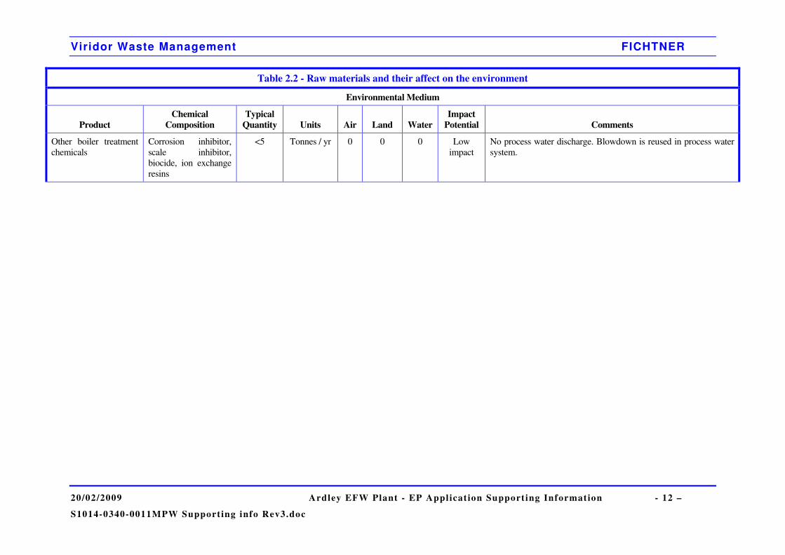
Table 2.2 - Raw materials and their affect on the environment
Environmental Medium
Product Chemical
Composition Typical
Quantity Units Air Land Water Impact
Potential Comments
Other boiler treatment chemicals
Corrosion inhibitor, scale inhibitor, biocide, ion exchange resins
<5 Tonnes / yr 0 0 0 Low impact
No process water discharge. Blowdown is reused in process water system.
Viridor Waste Management FICHTNER
20/02/2009 Ardley EFW Plant - EP Applicat ion Supporting Information - 13
S1014-0340-0011MPW Support ing info Rev3.doc
Various other materials will be required for the operation and maintenance of the plant, including:
a) Hydraulic oils and silicone based oils;
b) Electrical switchgear;
c) Refrigerant gases for the air conditioning plant;
d) Oxyacetylene, TIG, MIG welding gases;
e) CO2 / fire fighting foam agents;
f) Test and calibration gases.
These will be supplied to standard specifications offered by main suppliers. All chemicals will be handled in accordance with COSHH Regulations as part of the quality assurance procedures and full product data sheets will be available on site.
Periodic reviews of all materials used will be made in the light of new products and developments. Any significant change of material, where it may have an impact on the environment, will not be made without firstly assessing the impact and seeking approval from the Environment Agency.
The Operator will maintain a detailed inventory of raw materials used on site and have procedures for the regular review of new developments in raw materials.
2.1.2 Reagent Storage
In order to minimise contamination risk of process or surface water, all liquid chemicals stored on site will be kept inside bunded areas or stored in double skin vessels. In particular, diesel fuel will be held in a bunded storage tank. Spillage and leakage will be retained in these areas and treated locally.
Dry urea powder will be delivered in big bags and stored within the urea dosing room. Any spills will be contained and treated within the room.
Hydrated lime and activated carbon will be delivered to the plant for storage in silos. Both the lime and the activated carbon will be transported pneumatically from the delivery vehicle to the correct storage silo. Control is achieved through high level control and alarm. The top of the silo will be equipped with a vent fitted with a silo top filter which will be inspected regularly for leaks.

Viridor Waste Management FICHTNER
20/02/2009 Ardley EFW Plant - EP Applicat ion Supporting Information - 14
S1014-0340-0011MPW Support ing info Rev3.doc
2.1.3 Raw Materials Selection
2.1.3.1 Reagent selection
Acid Gas Abatement
Sodium bicarbonate, NaHCO3, can be substituted for hydrated lime, Ca(OH)2, in the dry FGT processes and Sector Guidance Note S5.01 requires both reagents to be considered in the BAT assessment. NaHCO3 has better solid handling properties and a significantly lower stoichiometric ratio than Ca(OH)2. NaHCO3 and Ca(OH)2 react with the acid gases to produce alkaline salts as the following equations illustrate:
)(2)(2)()()(3 ggsgs COOHNaClHClNaHCO ++→+ (Eq. 1)
)(2)(2)()(2 22)( gsgs OHCaClHClOHCa +→+ (Eq. 2)
In order to promote the reactions above, excess quantities of sodium bicarbonate or lime will be required. The excess reagent is lost in the residue. The ratio between the quantity of reagent supplied and the minimum required for the reaction is called the “stoichiometric ratio”.
For sodium bicarbonate, a stoichiometric ratio of 1.30 is required, whereas for lime, a stoichiometric ratio of around 1.8 is required. This initially appears to be economically advantageous for sodium bicarbonate in comparison to lime. However, due to the higher relative molecular weight, and the fewer molecules of acid gas reacting per molecule of NaHCO3, the overall consumption of sodium bi-carbonate is actually 61% higher than Ca(OH)2 on a mass basis. Hence, the difference in capital expenditure between the two options is minimal.
The cost of NaHCO3 is significantly higher than Ca(OH)2, with bicarbonate costing almost two times as much as hydrated lime. This makes sodium bicarbonate an uneconomic option in comparison to lime.
The cost of disposing of the residue must also be considered due to differences in quantity. Sodium based residues are more difficult to stabilise than lime residues; it has been assumed that the cost per tonne to landfill the sodium based residues is 20% higher than lime residues.
The stoichiometric ratio indicates that the amount of residue will be higher with the lime option. Due to the differences in relative molecular weight and the number of acid gas molecules reacting with each absorbent molecular, the lime system produces around 44% more residue than the sodium bi-carbonate option.
The two options are compared below, for a stoichiometric ratio of 1.8 for lime and 1.3 for sodium bicarbonate on the basis of the abatement of 1 kmol of HCl:
Viridor Waste Management FICHTNER
20/02/2009 Ardley EFW Plant - EP Applicat ion Supporting Information - 15
S1014-0340-0011MPW Support ing info Rev3.doc
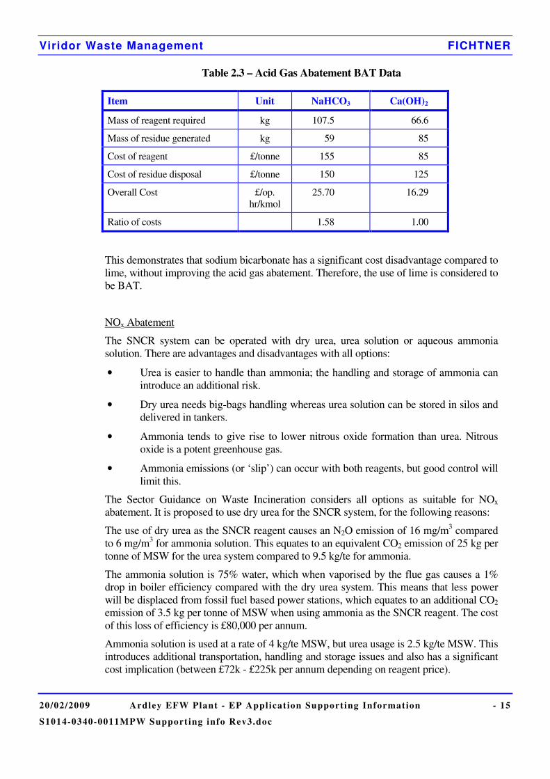
Table 2.3 – Acid Gas Abatement BAT Data
Item Unit NaHCO3 Ca(OH)2
Mass of reagent required kg 107.5 66.6
Mass of residue generated kg 59 85
Cost of reagent £/tonne 155 85
Cost of residue disposal £/tonne 150 125
Overall Cost £/op. hr/kmol
25.70 16.29
Ratio of costs 1.58 1.00
This demonstrates that sodium bicarbonate has a significant cost disadvantage compared to lime, without improving the acid gas abatement. Therefore, the use of lime is considered to be BAT.
NOx Abatement
The SNCR system can be operated with dry urea, urea solution or aqueous ammonia solution. There are advantages and disadvantages with all options:
• Urea is easier to handle than ammonia; the handling and storage of ammonia can introduce an additional risk.
• Dry urea needs big-bags handling whereas urea solution can be stored in silos and delivered in tankers.
• Ammonia tends to give rise to lower nitrous oxide formation than urea. Nitrous oxide is a potent greenhouse gas.
• Ammonia emissions (or ‘slip’) can occur with both reagents, but good control will limit this.
The Sector Guidance on Waste Incineration considers all options as suitable for NOx abatement. It is proposed to use dry urea for the SNCR system, for the following reasons:
The use of dry urea as the SNCR reagent causes an N2O emission of 16 mg/m3 compared to 6 mg/m3 for ammonia solution. This equates to an equivalent CO2 emission of 25 kg per tonne of MSW for the urea system compared to 9.5 kg/te for ammonia.
The ammonia solution is 75% water, which when vaporised by the flue gas causes a 1% drop in boiler efficiency compared with the dry urea system. This means that less power will be displaced from fossil fuel based power stations, which equates to an additional CO2 emission of 3.5 kg per tonne of MSW when using ammonia as the SNCR reagent. The cost of this loss of efficiency is £80,000 per annum.
Ammonia solution is used at a rate of 4 kg/te MSW, but urea usage is 2.5 kg/te MSW. This introduces additional transportation, handling and storage issues and also has a significant cost implication (between £72k - £225k per annum depending on reagent price).
Viridor Waste Management FICHTNER
20/02/2009 Ardley EFW Plant - EP Applicat ion Supporting Information - 16
S1014-0340-0011MPW Support ing info Rev3.doc
An additional emission of 12 kg of CO2 per tonne of MSW is therefore associated with the urea SNCR system. However, the ammonia SNCR system introduces an additional operating cost of at least £152,000 per annum or approximately £41 per tonne of CO2 avoided.
The Ardley EfW plant will still displace greenhouse gas emissions associated with landfill and fossil fuel based power generation by 190 kg CO2 per tonne of MSW. This means a net benefit of at least 56,800 tonnes of CO2 per year (as demonstrated in the greenhouse gas assessment provided in annex 5).
Ammonia is also a highly toxic chemical and the transport and handling of this chemical introduces additional risks and increases capital costs.
2.1.3.2 Auxiliary Fuel
There is no natural gas available on the site. Therefore, low sulphur gasoil will be used.
Viridor Waste Management FICHTNER
20/02/2009 Ardley EFW Plant - EP Applicat ion Supporting Information - 17
S1014-0340-0011MPW Support ing info Rev3.doc
2.1.4 Incoming Waste Management
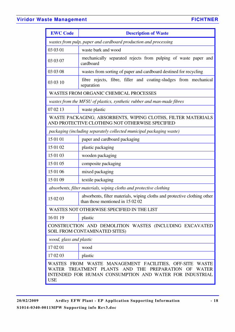
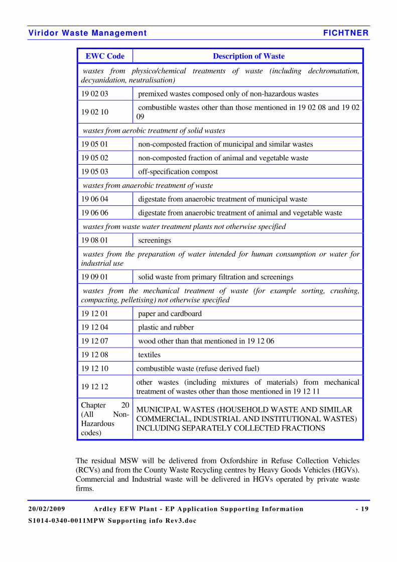
2.1.4.1 Waste to be Burned
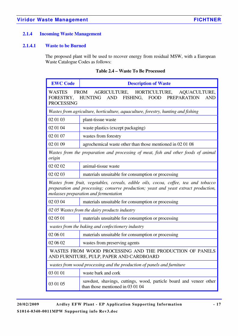
The proposed plant will be used to recover energy from residual MSW, with a European Waste Catalogue Codes as follows:
Table 2.4 – Waste To Be Processed
EWC Code Description of Waste
WASTES FROM AGRICULTURE, HORTICULTURE, AQUACULTURE, FORESTRY, HUNTING AND FISHING, FOOD PREPARATION AND PROCESSING
Wastes from agriculture, horticulture, aquaculture, forestry, hunting and fishing
02 01 03 plant-tissue waste
02 01 04 waste plastics (except packaging)
02 01 07 wastes from forestry
02 01 09 agrochemical waste other than those mentioned in 02 01 08
Wastes from the preparation and processing of meat, fish and other foods of animal origin
02 02 02 animal-tissue waste
02 02 03 materials unsuitable for consumption or processing
Wastes from fruit, vegetables, cereals, edible oils, cocoa, coffee, tea and tobacco preparation and processing; conserve production; yeast and yeast extract production, molasses preparation and fermentation
02 03 04 materials unsuitable for consumption or processing
02 05 Wastes from the dairy products industry
02 05 01 materials unsuitable for consumption or processing
wastes from the baking and confectionery industry
02 06 01 materials unsuitable for consumption or processing
02 06 02 wastes from preserving agents
WASTES FROM WOOD PROCESSING AND THE PRODUCTION OF PANELS AND FURNITURE, PULP, PAPER AND CARDBOARD
wastes from wood processing and the production of panels and furniture
03 01 01 waste bark and cork
03 01 05 sawdust, shavings, cuttings, wood, particle board and veneer other than those mentioned in 03 01 04
Viridor Waste Management FICHTNER
20/02/2009 Ardley EFW Plant - EP Applicat ion Supporting Information - 18
S1014-0340-0011MPW Support ing info Rev3.doc
EWC Code Description of Waste
wastes from pulp, paper and cardboard production and processing
03 03 01 waste bark and wood
03 03 07 mechanically separated rejects from pulping of waste paper and cardboard
03 03 08 wastes from sorting of paper and cardboard destined for recycling
03 03 10 fibre rejects, fibre, filler and coating-sludges from mechanical separation
WASTES FROM ORGANIC CHEMICAL PROCESSES
wastes from the MFSU of plastics, synthetic rubber and man-made fibres
07 02 13 waste plastic
WASTE PACKAGING; ABSORBENTS, WIPING CLOTHS, FILTER MATERIALS AND PROTECTIVE CLOTHING NOT OTHERWISE SPECIFIED
packaging (including separately collected municipal packaging waste)
15 01 01 paper and cardboard packaging
15 01 02 plastic packaging
15 01 03 wooden packaging
15 01 05 composite packaging
15 01 06 mixed packaging
15 01 09 textile packaging
absorbents, filter materials, wiping cloths and protective clothing
15 02 03 absorbents, filter materials, wiping cloths and protective clothing other than those mentioned in 15 02 02
WASTES NOT OTHERWISE SPECIFIED IN THE LIST
16 01 19 plastic
CONSTRUCTION AND DEMOLITION WASTES (INCLUDING EXCAVATED SOIL FROM CONTAMINATED SITES)
wood, glass and plastic
17 02 01 wood
17 02 03 plastic
WASTES FROM WASTE MANAGEMENT FACILITIES, OFF-SITE WASTE WATER TREATMENT PLANTS AND THE PREPARATION OF WATER INTENDED FOR HUMAN CONSUMPTION AND WATER FOR INDUSTRIAL USE
Viridor Waste Management FICHTNER
20/02/2009 Ardley EFW Plant - EP Applicat ion Supporting Information - 19
S1014-0340-0011MPW Support ing info Rev3.doc
EWC Code Description of Waste
wastes from physico/chemical treatments of waste (including dechromatation, decyanidation, neutralisation)
19 02 03 premixed wastes composed only of non-hazardous wastes
19 02 10 combustible wastes other than those mentioned in 19 02 08 and 19 02 09
wastes from aerobic treatment of solid wastes
19 05 01 non-composted fraction of municipal and similar wastes
19 05 02 non-composted fraction of animal and vegetable waste
19 05 03 off-specification compost
wastes from anaerobic treatment of waste
19 06 04 digestate from anaerobic treatment of municipal waste
19 06 06 digestate from anaerobic treatment of animal and vegetable waste
wastes from waste water treatment plants not otherwise specified
19 08 01 screenings
wastes from the preparation of water intended for human consumption or water for industrial use
19 09 01 solid waste from primary filtration and screenings
wastes from the mechanical treatment of waste (for example sorting, crushing, compacting, pelletising) not otherwise specified
19 12 01 paper and cardboard
19 12 04 plastic and rubber
19 12 07 wood other than that mentioned in 19 12 06
19 12 08 textiles
19 12 10 combustible waste (refuse derived fuel)
19 12 12 other wastes (including mixtures of materials) from mechanical treatment of wastes other than those mentioned in 19 12 11
Chapter 20 (All Non-Hazardous codes)
MUNICIPAL WASTES (HOUSEHOLD WASTE AND SIMILAR COMMERCIAL, INDUSTRIAL AND INSTITUTIONAL WASTES) INCLUDING SEPARATELY COLLECTED FRACTIONS
The residual MSW will be delivered from Oxfordshire in Refuse Collection Vehicles (RCVs) and from the County Waste Recycling centres by Heavy Goods Vehicles (HGVs). Commercial and Industrial waste will be delivered in HGVs operated by private waste firms.

Viridor Waste Management FICHTNER
20/02/2009 Ardley EFW Plant - EP Applicat ion Supporting Information - 20
S1014-0340-0011MPW Support ing info Rev3.doc
The total nominal fuel input capacity of the plant of 300,000 tonnes per year is based on an NCV of 9.2 MJ/kg.
The other factor which will affect total fuel input capacity will be the hours of operation. In some years, the plant may not need to be shutdown for as long a period, so that the fuel input capacity will increase.
Checks will be made on the paperwork accompanying each delivery to ensure that only waste for which the plant has been designed will be accepted.
Unacceptable waste will be rejected and returned to the originator or quarantined for later disposal, as appropriate, under the control of the Business Management System (BMS) procedures. Certain wastes will require specific action for safe storage and handling. The BMS will also contain procedures for controlling the blending of waste types to avoid mixing of incompatible wastes.
Over a year, the maximum throughput of the plant is expected to be no more than 300,000 tonnes.
2.1.4.2 Waste Handling
The procedures used will comply with the Indicative BAT requirements in the Sector Guidance Note.
Viridor Waste Management FICHTNER
20/02/2009 Ardley EFW Plant - EP Applicat ion Supporting Information - 21
S1014-0340-0011MPW Support ing info Rev3.doc
2.1.5 Waste Minimisation Audit (Minimising the Use of Raw Materials)
A number of specific techniques are employed to minimise the production of residues. All of these techniques meet the Indicative BAT requirements from the Sector Guidance Note on Waste Incineration.
2.1.5.1 Feedstock Homogeneity.
Improving feedstock homogeneity can improve the operational stability of the plant, leading to reduced reagent use and reduced residue production. The process of tipping MSW in the storage bunker and subsequent mixing by the cactus cranes will serve to improve the homogeneity of MSW from different deliveries.
2.1.5.2 Furnace Conditions
Furnace conditions will be optimised in order to minimise the quantity of residues arising for further disposal. Burnout in the furnace will reduce the LOI content of the bottom ash to less than 5% by optimising MSW feed rate and combustion air flows. SNCR reagent dosing will be optimised to prevent ammonia slip.
2.1.5.3 Flue Gas Treatment Control
Close control of the flue gas treatment system will minimise the use of reagents and hence minimise the residues produced.
2.1.5.4 Waste Management
Details of waste management procedures can be found in Section 2.7. In particular, bottom ash and residues from the flue gas treatment system will be stored and disposed of separately.
Viridor Waste Management FICHTNER
20/02/2009 Ardley EFW Plant - EP Applicat ion Supporting Information - 22
S1014-0340-0011MPW Support ing info Rev3.doc
2.1.6 Water Use
2.1.6.1 Overview
The main use of water at the plant will be to make-up the water for the boiler. The following key points should be noted:
• The water system has been designed with the key objective of minimal consumption of potable water
• Most of the steam produced will be recycled as condensate. The remainder will be lost as blowdown to prevent build-up of sludge and chemicals, through sootblowing and through continuously flowing sample points.
• Lost condensate will be replaced with demineralised water.
• Waste water from the process will be re-used in the bottom ash quench system.
• The facility will have completely separate foul sewer systems and storm water systems (surface drainage).
2.1.6.2 Potable and Amenity Water
Water for supplies for the offices and mess facilities will come from a potable water supply. The quantity of this water is expected to be small compared to the other water uses on site. Waste water from showers, toilets and other mess facilities will be handled separately by a package treatment plant.
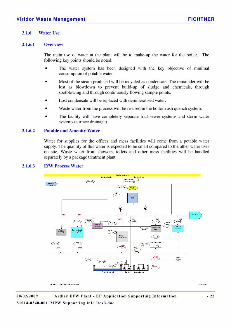
2.1.6.3 EfW Process Water
Viridor Waste Management FICHTNER
20/02/2009 Ardley EFW Plant - EP Applicat ion Supporting Information - 23
S1014-0340-0011MPW Support ing info Rev3.doc
Town water will be treated in a demineralisation plant (located on the plant and covered by this EP application) to produce feed water for the boilers. The demineralisation plant will have two streams so that one stream can continue operating whilst another is re-generating or on standby.
Waste water will be collected and treated in the waste water pit and then used in the bottom ash quenching system. Under normal operating conditions, waste water is generated from the following:
• Regeneration of the resins in the demineralised water treatment plant;
• Process effluent collected in site drainage system (e.g. boiler blowdown);
• Effluent generated through washing and maintenance procedures;
• Water run-off collected from the bottom ash quench;
The waste water pit provides settlement and chemical dosing of the recirculated bottom ash quench water. Sludge tankers will periodically remove the settled ash and boiler blowdown sludge from the waste water pit for offsite disposal. There will be no water discharge from the waste water pit or process water system; all water from the Energy from Waste plant will be reused within the building.
2.1.6.4 Bottom Ash Processing Water
A supply of process water is required for damping down of dust and for ensuring the correct conditions are present in the ash piles for maturation to take place. This water will be supplied from the dedicated lagoon.
Under normal operating conditions, water will enter the lagoon from the following sources:
• Rainwater from the surrounding area;
• Leachate from the ash processing plant due to the incoming bottom ash moisture content;
• Additional leachate from damping down of ash piles.
• Towns water supply for make-up as required.
The lagoon will provide settlement of any suspended solids in the leachate and allow recirculation to the processing facility to minimise water use and disposal requirements.
The volume of leachate requiring disposal is expected to be minimal (approx. 6m3/day) and will therefore be removed from the lagoon every few days by road-tanker and transferred to the existing Ardley Landfill leachate plant for treatment and subsequent discharge. It may also be possible to send the leachate to the EfW process water system during peak demand periods, but there will always be a requirement for disposal at the existing leachate treatment plant.
Spraying water onto the maturing ash piles is required for processing and dust suppression, but is also desirable since it encourages evaporation, which minimises the amount of leachate for disposal.
Viridor Waste Management FICHTNER
20/02/2009 Ardley EFW Plant - EP Applicat ion Supporting Information - 24
S1014-0340-0011MPW Support ing info Rev3.doc
2.2 Emissions
2.2.1 Emissions to Air
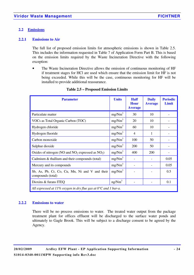
The full list of proposed emission limits for atmospheric emissions is shown in Table 2.5. This includes the information requested in Table 7 of Application Form Part B. This is based on the emission limits required by the Waste Incineration Directive with the following exception:
• The Waste Incineration Directive allows the omission of continuous monitoring of HF if treatment stages for HCl are used which ensure that the emission limit for HF is not being exceeded. While this will be the case, continuous monitoring for HF will be installed to provide additional reassurance.
Table 2.5 – Proposed Emission Limits
Parameter Units Half Hour
Average
Daily Average
Periodic Limit
Particulate matter mg/Nm3 30 10 -
VOCs as Total Organic Carbon (TOC) mg/Nm3 20 10 -
Hydrogen chloride mg/Nm3 60 10 -
Hydrogen fluoride mg/Nm3 4 1 -
Carbon monoxide mg/Nm3 100 50 -
Sulphur dioxide mg/Nm3 200 50 -
Oxides of nitrogen (NO and NO2 expressed as NO2) mg/Nm3 400 200 -
Cadmium & thallium and their compounds (total) mg/Nm3 - - 0.05
Mercury and its compounds mg/Nm3 - - 0.05
Sb, As, Pb, Cr, Co, Cu, Mn, Ni and V and their compounds (total)
mg/Nm3 - - 0.5
Dioxins & furans ITEQ ng/Nm3 - - 0.1
All expressed at 11% oxygen in dry flue gas at 0°C and 1 bar-a.
2.2.2 Emissions to water
There will be no process emissions to water. The treated water output from the package treatment plant for offices effluent will be discharged to the surface water ponds and ultimately to Gagle Brook. This will be subject to a discharge consent to be agreed by the Agency.
Viridor Waste Management FICHTNER
20/02/2009 Ardley EFW Plant - EP Applicat ion Supporting Information - 25
S1014-0340-0011MPW Support ing info Rev3.doc
2.2.3 Contaminated water
The EfW facility is supplied with fuel oil on an as needs basis with no provision for more flammable fuels except propane gas in bottles. All chemicals will be stored in an appropriate manner incorporating the use of bunding and other measures (such as acid and alkali resistant coatings) to ensure appropriate containment. The potential for accidents, and associated environmental impacts, is therefore limited.
Adequate quantities of spillage absorbent materials will be made available onsite, at easily accessible location(s), where liquids are stored. A site drainage plan, including the locations of foul and surface water drains and interceptors will be made available onsite, where practicable.
The diesel tanker offloading area is surfaced in concrete with falls to a gully and sump. The outlet to the surface water drain is controlled via interceptors and an oil water separator. The oil water interceptors are designed with an appropriate capacity to capture a spill during fuel delivery.
In the event of a fire, the fire fighting water will be contained within the waste bunker, all floors will slope towards the bunker to facilitate this. This water can be pumped out of a sump at the base of the bunker and removed from site. The bunker structure is designed as a water retaining structure. The process water system will have an isolation valve to isolate it in case of a fire.
According to the BMS, leaks and spillages will be divided into major and minor spills. In general a spill will be considered to be minor if it is entirely contained within the site boundary and does not contact a pollution pathway. An example of a minor spill would be a spill of fuel oil that is contained within a bund. A spill would be categorised as major when there is significant risk of the spilt material passing beyond the site boundary or transiting through a pollution pathway. An example of a major spill would be the release of any quantity of oil into the surface water drains.
The site will be required to publish an emergency plan to deal with the range of potential incidents / accidents on site. These are referred to as Unit Emergency Plans (UEPs). The UEPs will contain procedures for handling and reporting minor and major spillages.
Viridor operate a comprehensive reporting system for incidents / accidents. Any spillage, no matter how minor, will be reported to the Unit Manager and recorded. The Unit Manager will be responsible for the correct external reporting of incidents to any relevant parties and for ensuring that any resulting non-compliance or abnormal operation is corrected. The Unit Manager will also be responsible for maintaining the UEP register in accordance with BMS requirements as well as conducting tests and reviews of the procedures throughout the year.
Viridor Waste Management FICHTNER
20/02/2009 Ardley EFW Plant - EP Applicat ion Supporting Information - 26
S1014-0340-0011MPW Support ing info Rev3.doc
2.3 Monitoring Methods
2.3.1 Emissions Monitoring
Sampling and analysis of all pollutants including dioxins and furans will be carried out to CEN or equivalent standards (e.g. ISO, national, or international standards). This ensures the provision of data of an equivalent scientific quality.
The plant will be equipped with modern monitoring and data logging devices to enable checks to be made of process efficiency.
The purpose of monitoring has three main objectives.
1) To provide the information necessary for efficient and safe plant operation;
2) To warn the operator if any emissions deviate from predefined ranges;
3) To provide records of emissions and events for the purposes of demonstrating regulatory compliance.
2.3.1.1 Monitoring Emissions to Air
The following parameters at the stack will be monitored and recorded continuously using a Continuous Emissions Monitoring System (CEMS): • Oxygen; • Carbon Monoxide; • Hydrogen Chloride; • Hydrogen Fluoride • Sulphur dioxide; • Nitrogen oxides; • Ammonia; • VOCs. • Particulates;
In addition, the water vapour content, temperature and pressure of the flue gases will be monitored so that the emission concentrations can be reported at the reference conditions required by the Waste Incineration Directive.
The continuously monitored emissions concentrations will also be checked by an independent testing company at frequencies agreed with the Environment Agency.
There will be a duty CEMS for each line and one stand-by CEMS which can be switched to either line. This will ensure that there is continuous monitoring data available even if there is a problem with either duty CEMS system.
The following parameters will also be monitored by means of spot sampling at frequencies agreed with the Environment Agency: • Heavy Metals; • Organic Compounds (including PAHs and dioxin-like PCBs); • Dioxins and furans.
Viridor Waste Management FICHTNER
20/02/2009 Ardley EFW Plant - EP Applicat ion Supporting Information - 27
S1014-0340-0011MPW Support ing info Rev3.doc
The methods and standards used for emissions monitoring will be in compliance with guidance note S5.01 and the Waste Incineration Directive. In particular, the CEMS equipment will be certified to the MCERTS standard and will have certified ranges which are no greater than 1.5 times the relevant daily average emission limit.
It is anticipated that
• HCl, CO, SO2, NOx (NO+NO2), HF and NH3 will be measured by an FTIR type multi-gas analyser;
• VOC will be measured by a FID type analyser;
• Particulate matter will be measured by an opacimeter; and
• O2 will be monitored by a zirconium probe
The frequency of periodic measurements will comply with the Waste Incineration Directive as a minimum. The flue gas sampling techniques and the sampling platform will comply with Environment Agency Technical Guidance Notes M1 and M2.
The emission limit values under the Waste Incineration Directive do not apply during start-up and shutdown when the plant is incinerating waste. Therefore, a signal would be sent from the main plant control system to the CEMS package to indicate when the plant is operational and burning waste. The averages would only be calculated when this signal was sent, but raw monitoring data would be retained for inspection. Start-up ends when all the following conditions are met:
• The feed chute damper open, feeder ram, grate and ash extractors are all running;
• Exhaust gas O2 is less than 15% (wet measurement); and
• The combustion grate is fully covered with waste
Shutdown begins when all the following conditions are met:
• The feed chute damper is closed;
• Shutdown burner is in service; and
• Exhaust gas O2 is equal or above than 15% (wet measurement).
2.3.1.2 Monitoring Emissions to Land
Disposal of residues to land will comply with all relevant legislation. In particular the bottom ash will comply with the WID criterion of Total Organic Carbon less than 3%. Compliance with the TOC criterion will be demonstrated during commissioning and checked at periodic intervals agreed with the Environment Agency throughout the life of the plant. Testing for TOC will be conducted by an independent laboratory.
2.3.1.3 Monitoring Emissions to Water
No monitoring is proposed for the sewage treatment plant, but this will be determined by the discharge consent.
Viridor Waste Management FICHTNER
20/02/2009 Ardley EFW Plant - EP Applicat ion Supporting Information - 28
S1014-0340-0011MPW Support ing info Rev3.doc
2.3.2 Environmental Monitoring (Beyond the Installation)
As part of the air quality assessment submitted with this application, the concentration of nitrogen dioxide, sulphur dioxide, hydrogen chloride, hydrogen fluoride and VOCs in ambient air was measured at a number of locations around the site. Once the plant is operational, it is anticipated that this survey will be repeated for nitrogen dioxide and sulphur dioxide to confirm that emissions from the facility do not have a significant impact on local air quality.
2.3.3 Monitoring of Process Variables
The following process variables have particular potential to influence emissions:
• MSW throughput will be recorded to enable comparison with the design throughput. As a minimum, daily and annual throughput will be recorded;
• Combustion temperature will be monitored at a suitable position to demonstrate compliance with the requirement for a residence time of 2 seconds at a temperature of at least 850°C;
• The oxygen concentration will be measured at the outlet from the boiler;
• The differential pressure across the bag filters will be measured, in order to optimise the performance of the cleaning system and to detect bag failures;
• The concentration of HCl in the flue gases upstream of the flue gas treatment system will be measured in order to optimise the performance of the emissions abatement equipment.
Viridor Waste Management FICHTNER
20/02/2009 Ardley EFW Plant - EP Applicat ion Supporting Information - 29
S1014-0340-0011MPW Support ing info Rev3.doc
2.4 Technology Selection
2.4.1 Combustion Technology
It is proposed that the combustion technology for the plant will be a moving grate furnace.
This is the leading technology in the UK and Europe for the combustion of raw residual MSW. The moving grate comprises of inclined fixed and moving bars that will move the waste from the feed inlet to the residue discharge. The grate movement turns and mixes the waste along the surface of the grate to ensure that all waste is exposed to the combustion process.
The Incinerator Sector Guidance Note (S5.01) and the European BAT Reference documents discuss a number of alternative technologies for the combustion of waste.
1) Moving Grate Furnaces
As stated in the Sector Guidance Note, these are designed to handle large volumes of waste.
2) Fixed Hearth
These are not considered suitable for large volumes of waste. They are best suited to low volumes of consistent waste.
3) Pulsed Hearth
Pulsed hearth technology has been used for municipal waste in the past, as well as other solid wastes. However, there have been difficulties in achieving reliable and effective burnout of waste and it is considered that the burnout criteria required by WID would be difficult to achieve.
4) Rotary Kiln
Rotary Kilns have achieved good results with clinical waste, but they have not been used in the UK for municipal waste. The energy conversion efficiency of a rotary kiln is lower than that of a moving grate due to the large areas of refractory lined combustion chamber.
An oscillating kiln is used for municipal waste at one site in England and a number of sites in France. The energy conversion efficiency is lower than that of a moving grate for the same reasons as for a rotary kiln. In addition, the capacity per unit is limited to 8 tonnes per hour and for this application it would need up to 5 furnaces to achieve the design throughput, which is not economically feasible.
Viridor Waste Management FICHTNER
20/02/2009 Ardley EFW Plant - EP Applicat ion Supporting Information - 30
S1014-0340-0011MPW Support ing info Rev3.doc
5) Pyrolysis/Gasification
Various suppliers are developing pyrolysis and gasification systems for the disposal of municipal waste. However, it is not considered that any of these technologies can be considered to be proven. Pyrolysis and gasification systems which generate a syngas can theoretically take advantage of gas engines or gas turbines, which are more efficient that a standard steam turbine cycle. However, the losses associated with making the syngas and the additional electricity consumption of the site due to the waste pretreatment requirements mean that the overall efficiency is no higher than for a combustion plant and is generally lower. This means that a combustion plant will have a more beneficial effect on climate change.
Plasma gasification can theoretically produce a much more useful syngas than thermal gasification, but has a much higher electrical parasitic load and is in the early stages of commercial development for municipal waste treatment. It has been used successfully for treatment of hazardous wastes (the European BAT reference document for waste incineration refers entirely to plasma gasification for destruction of gaseous CFCs and other ozone depleting substances). However, there are no reference plants recovering energy from municipal waste in Europe (The only large scale commercial plant constructed in Europe closed in 2004). A handful of municipal waste plants are operational worldwide, but the largest plant only has the capacity to treat a fraction of the 300,000 tonnes per annum required waste throughput.
Therefore, pyrolysis and gasification are not considered to be suitable alternatives to the current facility design.
6) Fluidised Bed
These are designed for the combustion of relatively homogeneous waste. For residual MSW, the waste would need to be pre-treated before feeding to the fluidised bed, which would lead to additional energy consumption and a larger building. The pre-treatment can also lead to higher quantities of rejected material. Where MSW is treated at a material recycling facility, the residues from the MRF may already be suitable for feeding to the fluidised bed. This does not apply to residues from kerbside collection schemes, which would need some pre-treatment, including shredding and metals removal as a minimum, before feeding to the fluidised bed.
While fluidised bed combustion can lead to slightly lower NOx generation, the injection of ammonia or urea is still required to achieve the emission limits specified in WID.
Experience in the UK of fluidised bed combustion of MSW has been limited. Two plants are operational, but both have had significant operational problems. One is operating well below its design capacity while the other is still being commissioned. Viridor do not consider that they can be considered a reliable technology at this stage.
In summary, moving grate technology is proposed for this plant as it is believed that it represents the best choice when balancing the factors of mechanical reliability, energy efficiency, environmental impact and costs.
Viridor Waste Management FICHTNER
20/02/2009 Ardley EFW Plant - EP Applicat ion Supporting Information - 31
S1014-0340-0011MPW Support ing info Rev3.doc
2.4.2 Flue Gas Recirculation (FGR)
The proposed installation will not employ flue gas recirculation.
It is important to understand that FGR is not a bolt-on abatement technique. The recirculation of a proportion of the flue gases into the combustion chamber to replace some of the secondary air changes the operation of the plant in various ways, by changing the temperature balance and increasing turbulence. This requires the boiler to be redesigned to ensure that the air distribution remains even.
Some suppliers of grates have designed their combustion systems to operate with FGR and these suppliers can gain benefits of reduced NOx generation from the use of FGR. Other suppliers of grates have focussed on reducing NOx generation through the control of primary and secondary air and the grate design, and these suppliers gain little if any benefit from the use of FGR.
The supplier of the Ardley plant has not included FGR in their design. The design can meet the required emission limits for NOx by using SNCR, therefore the applicant does not intend to include FGR.
2.4.3 NOx Reduction System
NOx levels will primarily be controlled by monitoring the combustion air. Selective non-catalytic NOx reduction (SNCR) methods will also be installed, using dry urea as the reagent.
The use of Selective Catalytic Reduction (SCR) has also been considered. In this technique, ammonia is injected into the flue gases immediately upstream of a reactor vessel containing layers of catalyst. The reaction is most efficient in the temperature range 200 to 350°C. The catalyst is expensive and to achieve a reasonable working life, it is necessary to install the SCR downstream of the flue gas treatment plant. This is because the flue gas treatment plant removes dust which would otherwise cause deterioration of the catalyst.
Since the other flue gas cleaning reactions take place at an optimum temperature of around 140°C, the flue gases have to be reheated before entering the SCR. This requires some thermal energy which would otherwise be converted to electrical power output, reducing the overall energy recovery efficiency of the facility. The catalytic reactor also creates additional pressure losses to be compensated by a bigger exhaust fan, reducing further the overall energy efficiency.
SNCR is proven to reduce NOx emissions to a low level and meet the WID emissions limits. Both techniques are listed in guidance note S5.01 and the relevant European BAT reference document as potentially representing BAT, therefore an assessment of these two options has been carried out, and is reported below.
Viridor Waste Management FICHTNER
20/02/2009 Ardley EFW Plant - EP Applicat ion Supporting Information - 32
S1014-0340-0011MPW Support ing info Rev3.doc
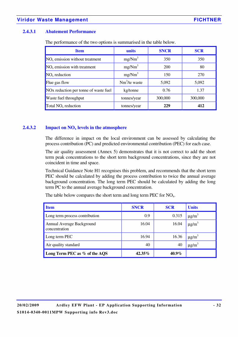
2.4.3.1 Abatement Performance
The performance of the two options is summarised in the table below.
Item units SNCR SCR
NOx emission without treatment mg/Nm3 350 350
NOx emission with treatment mg/Nm3 200 80
NOx reduction mg/Nm3 150 270
Flue gas flow Nm3/te waste 5,092 5,092
NOx reduction per tonne of waste fuel kg/tonne 0.76 1.37
Waste fuel throughput tonnes/year 300,000 300,000
Total NOx reduction tonnes/year 229 412
2.4.3.2 Impact on NOx levels in the atmosphere
The difference in impact on the local environment can be assessed by calculating the process contribution (PC) and predicted environmental contribution (PEC) for each case.
The air quality assessment (Annex 5) demonstrates that it is not correct to add the short term peak concentrations to the short term background concentrations, since they are not coincident in time and space.
Technical Guidance Note H1 recognises this problem, and recommends that the short term PEC should be calculated by adding the process contribution to twice the annual average background concentration. The long term PEC should be calculated by adding the long term PC to the annual average background concentration.
The table below compares the short term and long term PEC for NOx.
Item SNCR SCR Units
Long term process contribution 0.9 0.315 µg/m3
Annual Average Background concentration
16.04 16.04 µg/m3
Long term PEC 16.94 16.36 µg/m3
Air quality standard 40 40 µg/m3
Long Term PEC as % of the AQS 42.35% 40.9%
Viridor Waste Management FICHTNER
20/02/2009 Ardley EFW Plant - EP Applicat ion Supporting Information - 33
S1014-0340-0011MPW Support ing info Rev3.doc
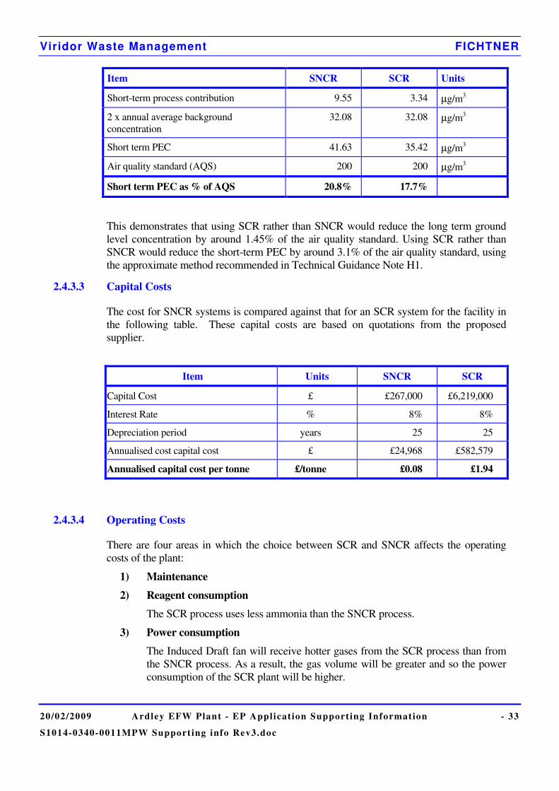
Item SNCR SCR Units
Short-term process contribution 9.55 3.34 µg/m3
2 x annual average background concentration
32.08 32.08 µg/m3
Short term PEC 41.63 35.42 µg/m3
Air quality standard (AQS) 200 200 µg/m3
Short term PEC as % of AQS 20.8% 17.7%
This demonstrates that using SCR rather than SNCR would reduce the long term ground level concentration by around 1.45% of the air quality standard. Using SCR rather than SNCR would reduce the short-term PEC by around 3.1% of the air quality standard, using the approximate method recommended in Technical Guidance Note H1.
2.4.3.3 Capital Costs
The cost for SNCR systems is compared against that for an SCR system for the facility in the following table. These capital costs are based on quotations from the proposed supplier.
Item Units SNCR SCR
Capital Cost £ £267,000 £6,219,000
Interest Rate % 8% 8%
Depreciation period years 25 25
Annualised cost capital cost £ £24,968 £582,579
Annualised capital cost per tonne £/tonne £0.08 £1.94
2.4.3.4 Operating Costs
There are four areas in which the choice between SCR and SNCR affects the operating costs of the plant:
1) Maintenance
2) Reagent consumption
The SCR process uses less ammonia than the SNCR process.
3) Power consumption
The Induced Draft fan will receive hotter gases from the SCR process than from the SNCR process. As a result, the gas volume will be greater and so the power consumption of the SCR plant will be higher.
Viridor Waste Management FICHTNER
20/02/2009 Ardley EFW Plant - EP Applicat ion Supporting Information - 34
S1014-0340-0011MPW Support ing info Rev3.doc
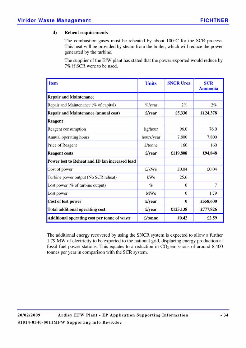
4) Reheat requirements
The combustion gases must be reheated by about 100°C for the SCR process. This heat will be provided by steam from the boiler, which will reduce the power generated by the turbine.
The supplier of the EfW plant has stated that the power exported would reduce by 7% if SCR were to be used.
Item Units SNCR Urea SCR Ammonia
Repair and Maintenance
Repair and Maintenance (% of capital) %/year 2% 2%
Repair and Maintenance (annual cost) £/year £5,330 £124,378
Reagent
Reagent consumption kg/hour 96.0 76.0
Annual operating hours hours/year 7,800 7,800
Price of Reagent £/tonne 160 160
Reagent costs £/year £119,808 £94,848
Power lost to Reheat and ID fan increased load
Cost of power £/kWe £0.04 £0.04
Turbine power output (No SCR reheat) kWe 25.6
Lost power (% of turbine output) % 0 7
Lost power MWe 0 1.79
Cost of lost power £/year 0 £558,600
Total additional operating cost £/year £125,138 £777,826
Additional operating cost per tonne of waste £/tonne £0.42 £2.59
The additional energy recovered by using the SNCR system is expected to allow a further 1.79 MW of electricity to be exported to the national grid, displacing energy production at fossil fuel power stations. This equates to a reduction in CO2 emissions of around 8,400 tonnes per year in comparison with the SCR system.
Viridor Waste Management FICHTNER
20/02/2009 Ardley EFW Plant - EP Applicat ion Supporting Information - 35
S1014-0340-0011MPW Support ing info Rev3.doc
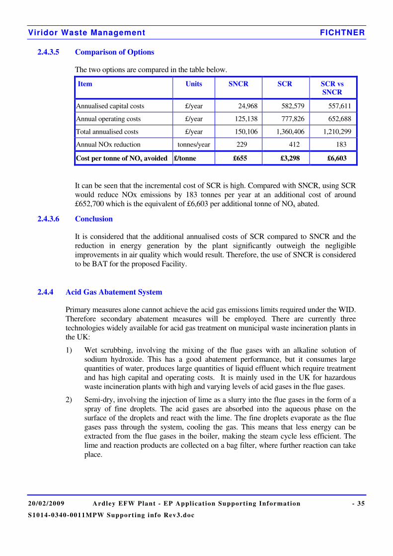
2.4.3.5 Comparison of Options
The two options are compared in the table below.
Item Units SNCR SCR SCR vs SNCR
Annualised capital costs £/year 24,968 582,579 557,611
Annual operating costs £/year 125,138 777,826 652,688
Total annualised costs £/year 150,106 1,360,406 1,210,299
Annual NOx reduction tonnes/year 229 412 183
Cost per tonne of NOx avoided £/tonne £655 £3,298 £6,603
It can be seen that the incremental cost of SCR is high. Compared with SNCR, using SCR would reduce NOx emissions by 183 tonnes per year at an additional cost of around £652,700 which is the equivalent of £6,603 per additional tonne of NOx abated.
2.4.3.6 Conclusion
It is considered that the additional annualised costs of SCR compared to SNCR and the reduction in energy generation by the plant significantly outweigh the negligible improvements in air quality which would result. Therefore, the use of SNCR is considered to be BAT for the proposed Facility.
2.4.4 Acid Gas Abatement System
Primary measures alone cannot achieve the acid gas emissions limits required under the WID. Therefore secondary abatement measures will be employed. There are currently three technologies widely available for acid gas treatment on municipal waste incineration plants in the UK:
1) Wet scrubbing, involving the mixing of the flue gases with an alkaline solution of sodium hydroxide. This has a good abatement performance, but it consumes large quantities of water, produces large quantities of liquid effluent which require treatment and has high capital and operating costs. It is mainly used in the UK for hazardous waste incineration plants with high and varying levels of acid gases in the flue gases.
2) Semi-dry, involving the injection of lime as a slurry into the flue gases in the form of a spray of fine droplets. The acid gases are absorbed into the aqueous phase on the surface of the droplets and react with the lime. The fine droplets evaporate as the flue gases pass through the system, cooling the gas. This means that less energy can be extracted from the flue gases in the boiler, making the steam cycle less efficient. The lime and reaction products are collected on a bag filter, where further reaction can take place.
Viridor Waste Management FICHTNER
20/02/2009 Ardley EFW Plant - EP Applicat ion Supporting Information - 36
S1014-0340-0011MPW Support ing info Rev3.doc
3) Dry, involving the injection of solid lime into the flue gases as a powder. The lime is collected on a bag filter to form a cake and most of the reaction between the acid gases and the lime takes place as the flue gases pass through the filter cake. In its basic form, the dry system reaction efficiency is lower and therefore it consumes more lime than the semi-dry system. However, this can be improved by recirculating the flue gas treatment residues, which contain unreacted lime and reinjecting into the flue gases. This approach reduces the reagent consumption to similar levels as the semi-dry system for similar acid gas abatement performance. It also has the additional benefit of recirculating the activated carbon, which helps to further reduce dioxin emissions.
Wet scrubbing is not considered to be suitable, due to the production of a liquid effluent which would require additional treatment on site.
The dry and semi-dry acid gas treatment technologies provide similar reduction performance and both are proven capable of achieving the limits in the Waste Incineration Directive. Therefore neither of these technologies can clearly be favoured on air emissions performance grounds and further assessment is required:
The main differences between the processes are:
1) Reagent Consumption
The semi-dry system consumes slightly less lime than the dry processes.
2) Residue Generation
The dry process generates slightly more residue than the semi-dry process, due to the difference in lime consumption.
3) Water consumption
The semi-dry process consumes around 120 m3 water per day to produce the lime slurry, which is then lost in the flue gases due to evaporation. The dry lime system requires no water addition.
4) Electricity Consumption & Generation
The semi-dry process consumes slightly less electricity than the dry process.
The evaporation of water in the semi dry system removes heat from the flue gases which, in the dry system is usefully extracted from the flue gases in the boiler, increasing the efficiency of the plant and thereby allowing more electricity to be displaced from fossil-fuel power stations. The additional energy recovered by using a dry lime system is expected to allow a further 0.89 MW of electricity to be exported to the national grid. This equates to a reduction in CO2 emissions of around 4200 tonnes per year in comparison with the semi-dry system.
5) Financial Costs
Analysis of the annual costs, in terms of both capital and operating costs, demonstrates that no technology has a clear financial benefit.
Wet, dry or semi-dry systems can be considered to represent BAT by Sector Guidance Note S5.01. It is considered that a dry system is BAT for the plant, due to the benefit of additional electricity generation and the displacement of additional electricity from fossil-fuel power stations and minimisation of water usage.
Viridor Waste Management FICHTNER
20/02/2009 Ardley EFW Plant - EP Applicat ion Supporting Information - 37
S1014-0340-0011MPW Support ing info Rev3.doc
2.4.5 Steam Condenser
The plant will operate an Air Cooled Condenser (ACC) to condense the steam output from the turbine to allow return of the condensate to the boiler. The two main alternatives to an ACC are a water cooled condenser or an evaporative condenser and all are considered in Sector Guidance Note S5.01 as potential BAT solutions. The former uses a recirculating water supply to condense the steam and the latter uses water which is evaporated directly from the condenser surface and lost to the atmosphere to provide the required cooling.
The main advantage of both of these water based systems is that they are less susceptible to condenser efficiency fluctuation with changing air temperature. High air temperatures in the summer with an Air Cooled Condenser can result in insufficient condensing power and subsequently reduce the efficiency of the generating turbine.
The disadvantage of these systems is the significant volume of make-up water required, which in the absence of a local river of sufficient size would need to be taken from the main town water supply. Chemical additives are also needed which means that effluent disposal is a problem for a water cooled condenser. In winter there is a risk of freezing, and maintenance costs are high due to the wet nature of the technology. In the case of evaporative condensers there is also the significant potential for release of water vapour plumes.
It is considered that the additional potable water use and the potential for visible plumes mean that water based condensers do not represent the best technology available for the plant. In addition, the ACC has been designed and guaranteed by the technology supplier with enough additional capacity to maintain turbine efficiency during the summer.
2.4.6 Bottom Ash Processing
The facility will operate an on site ash processing plant with leachate collected in a lagoon and reused for further ash processing. Excess leachate will be transferred by road-tanker to the existing Ardley Landfill leachate plant for treatment. Sector Guidance for Recovery and disposal of waste S5.06 has been considered in the BAT assessment of the bottom ash processing plant.
2.4.6.1 Ash Recovery Methods
The alternatives to processing the bottom ash in this way would be to send the ash to a similar processing facility off-site, or simply to “do nothing” and send the ash directly to non-hazardous landfill. The latter option involves landfilling of 69,600 tonnes of ash per annum (after metals removal). An ash processing facility is relatively simple to construct and operate and recovers around 62,100 tonnes of this ash for use as secondary aggregate with only 7,500 tonnes still sent to landfill. Any ash sent directly to landfill would leach contaminants into the landfill over a number of years. Ash processed into aggregate involves controlled maturation over a period of weeks and provides a stabilised end product.
On-site processing of bottom ash will be very similar in operation to off-site methods with the advantage that the transport requirements are significantly reduced and leachate disposal can be handled by an existing treatment plant.
It is therefore considered that processing the ash into an aggregate on-site represents Best Available Techniques.
Viridor Waste Management FICHTNER
20/02/2009 Ardley EFW Plant - EP Applicat ion Supporting Information - 38
S1014-0340-0011MPW Support ing info Rev3.doc
2.4.6.2 Fugitive dust emissions
The mechanical processing equipment for size separation and metals recovery will be housed within a covered area of the ash processing plant. The maturation stockpiles will be uncovered, but contained within a wall to provide a windbreak. An alternative would be to house the entire processing facility including the large open stockpile area. This would minimise the risk of fugitive dust emissions, but the process of maturing the ash would still require water to be sprayed onto the stockpiles to enable chemical stabilisation. This significant volume of water would no longer be supplied as rainfall. The moisture levels required for maturation are high enough that dust emissions from the stockpiles do not pose a risk and in combination with the use of a wall as a windbreak is considered to manage the risk of dust emissions.
The mechanical processing of the bottom ash can raise dust, but this will be prevented by good design with enclosed conveyers and trommels.
Typically the only dust emissions risk from a bottom ash processing facility is from road vehicles raising dry dust from the road surfaces. This will be managed by regular wheel and road cleaning and damping down of road surfaces.
It is considered that providing a roof over the entire facility does not represent BAT due to the significant expense of this option and the additional water requirements for processing. The limited dust emissions risk posed by open storage is mitigated by the required moisture conditions of the ash stockpiles.
2.4.6.3 Leachate treatment
The alternative disposal methods for excess leachate would be to use the leachate in the EfW process water system, to discharge directly into a sewer after seeking a trade effluent consent, or to treat the leachate in a new on-site treatment plant and discharge into the Gagle Brook.
• The EfW process water system does not have spare capacity for using this leachate.
• There is no sewer available on site, and a new connection is not required for the rest of the plant. A dedicated sewer connection cannot be justified since the volume of leachate produced is expected to be small and the existing landfill leachate treatment plant can easily process this effluent.
• A dedicated treatment plant with discharge to Gagle brook is not considered BAT since there is an existing treatment plant (with discharge to sewer) on the landfill site. This treatment plant has been assessed as having adequate spare capacity and can process the contaminants in the leachate. A new treatment plant and discharge to surface water introduces unnecessary environmental risk.
The alternative method for transfer of the leachate to the landfill treatment plant would be to pump the leachate via a 1 km pipeline across the landfill site. The volume of leachate to be transferred is small (approx. 6m3/day) and is therefore easily handled by two road tanker journeys per week. Constructing a pipeline and pumping station introduces unnecessary risk from leaks and subsequent groundwater contamination. This is considered to be a potential problem since the landfill is still operational.
Viridor Waste Management FICHTNER
20/02/2009 Ardley EFW Plant - EP Applicat ion Supporting Information - 39
S1014-0340-0011MPW Support ing info Rev3.doc
2.5 Specific Information required by the Waste Incineration Directive
This section contains information on how the plant will be designed, equipped and run to make sure it meets the requirements of Council Directive 2000/76/EC.
2.5.1 Furnace Requirements
Legislative Obligations – Waste Incineration Directive (2000/76/EC)
1) The design of the combustors will ensure that all gases resulting from the combustion of waste are maintained at or above 850ºC for at least 2 seconds;
2) Sufficient oxygen levels will be maintained to ensure good combustion. The minimum oxygen concentration at the exit from the boiler will be 6.9% (based on wet flue gas).
3) Auxiliary burners, fired with fuel oil are used to automatically maintain furnace conditions, again controlled by the combustion control system;
4) Measures will be included to minimise the amount and harmfulness of residues formed from the combustion process. The bottom ash from the combustion process will not exceed 5% Loss on Ignition (LOI).
5) Dry urea will be injected into the combustion chamber to reduce NOx emissions.
Moving Grate Operation and Combustion Air
The MSW will be transferred onto the moving grate from the feeding chutes by hydraulic power feeding units. Fixed and moving sections on the inclined grate will move the waste from the feed inlet to the residue discharge. The grate movements mix the waste along the surface of the grate to ensure that all waste is exposed to the combustion process.
Primary air for combustion will be fed to the underside of the grates by inverter-driven fans. Secondary air will also be admitted above the grates to create turbulence and ensure complete combustion with minimum levels of oxides of nitrogen (NOx). The volume of both primary and secondary air will be regulated by a combustion control system.
The combustion chamber and associated outlet gas ducts will be designed to be as air-tight as possible and will be maintained under a slight negative pressure to prevent releases into the atmosphere.
During operation the temperature in the combustion chamber will be continuously monitored and recorded to demonstrate compliance with the Waste Incineration Directive. The combustion control system will be an automated fully adjustable system, including the monitoring of combustion and temperature conditions of the grate, modification of the waste feed rate and the control of primary and secondary air.
Supplementary Burners and Fuels:
• Supplementary burners will be provided for start-up and shut-down and to maintain the combustion chamber temperatures above the legislative requirements of 850ºC during operation. They will be automatically initiated by the combustion control systems.
• The auxiliary fuel used will be low sulphur gas oil
Viridor Waste Management FICHTNER
20/02/2009 Ardley EFW Plant - EP Applicat ion Supporting Information - 40
S1014-0340-0011MPW Support ing info Rev3.doc
2.5.1.1 Validation of Combustion Conditions
The plant will be designed to provide a residence time, after the last injection of combustion air, of more than two seconds at a temperature of at least 850°C. This criterion will be demonstrated using Computational Fluid Dynamic (CFD) modelling during the design stage and confirmed by comparison of the CFD model with the actual gas temperatures measured at various points within the boiler during commissioning.
It will also be demonstrated during commissioning that the Plant can achieve complete combustion by measuring concentrations of carbon monoxide, volatile organic compounds and dioxins in the flue gases and LOI of the bottom ash.
During the operational phase, the temperature at the 2 seconds residence time point will be monitored to ensure that it remains above 850oC. The location of the temperature probes will be selected using the results of the CFD model. If it is not possible to locate the temperature probes at precisely the 2 seconds residence time point then a correction factor will be applied to the measured temperature.
2.5.1.2 Measuring Oxygen Levels
The oxygen concentration at the boiler exit will be monitored and controlled to ensure that there will always be adequate oxygen for complete combustion of combustible gases. Oxygen concentration will be controlled by regulating combustion airflows and MSW feed rate.
2.5.1.3 Combustion Control
The plant will be controlled from the Central Control Room. A modern control system, incorporating the latest advances in control and instrumentation technology, will be used to control operations, optimising the process relative to efficient heat release, good burn-out and minimum particle carry-over. The system will control and/or monitor the main features of the plant operation including, but not limited to the following:
• primary air;
• secondary air;
• MSW feed rate;
• SNCR system;
• flue gas oxygen concentration at the boiler exit;
• flue gas composition at the stack;
• combustion process;
• boiler feed pumps and feedwater control;
• steam flow at the boiler outlet;
• steam outlet temperature;
• boiler drum level control;
• flue gas control;
Viridor Waste Management FICHTNER
20/02/2009 Ardley EFW Plant - EP Applicat ion Supporting Information - 41
S1014-0340-0011MPW Support ing info Rev3.doc
• power generation;
• steam turbine exhaust pressure.
The response times for instrumentation and control devices will be designed to be fast enough to ensure efficient control.
2.5.1.4 Waste Charging
The EfW plant will meet the indicative BAT requirements outlined in the Incinerator Sector Guidance Note for waste charging and the specific requirements of WID:
• The combustion control and feeding system will be fully in line with the requirements of WID. The conditions within the furnace will be continually monitored to ensure that optimal conditions are maintained and that the mandatory WID emission limits are not exceeded. Auxiliary burners fired with fuel oil will be installed and will be used to maintain the temperature in the combustion chamber.
• The waste charging and feeding systems will be interlocked to prevent waste charging when the furnace temperature is below 850ºC, both during start-up and if the temperature falls below 850°C during operation;
• The waste charging and feeding systems will also be interlocked to prevent waste charging if the emissions to atmosphere are in excess of an emission limit value;
• Following loading into the feeding chutes by the cactus grab, the waste will be transferred onto the grates by hydraulic powered feeding units.
• The backward flow of combustion gases and the premature ignition of wastes will be prevented by keeping the chute full of waste and by keeping the furnace under negative pressure.
• A level detector will monitor the amount of waste in the feed chute and an alarm will be sounded if the waste falls below the safe minimum level. Secondary air will be injected from nozzles in the wall of the furnace to control flame height and the direction of air and flame flow.
The feed rate to the furnace will be controlled by the combustion control system.
2.5.1.5 Bag Filter Operation
The bag filter will not require a flue gas bypass station.
There is a risk that during normal operation, pollutant residues can build up in the inlet duct to a bypass station. If the bypass is then operated during startup, as is common until the bag filter is at operating temperature, these residues will be emitted from the stack with no abatement. The bag filter can be preheated allowing startup without a bypass, which is considered to represent BAT.
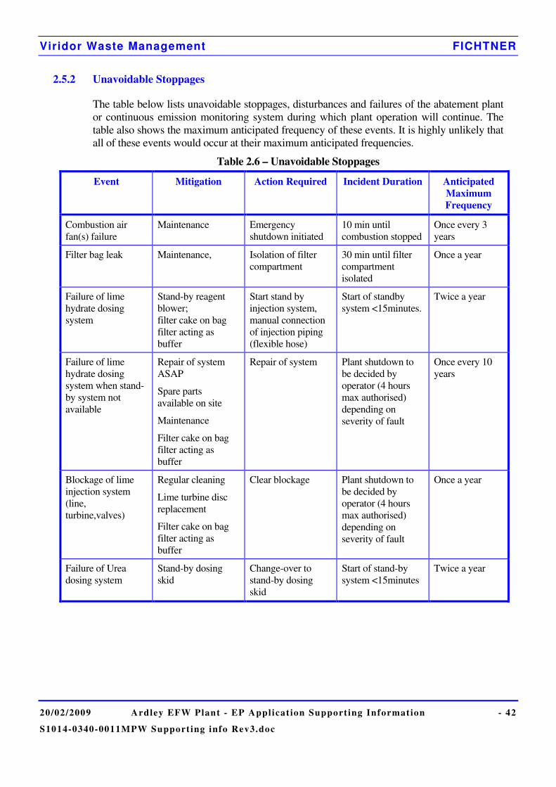
Viridor Waste Management FICHTNER
20/02/2009 Ardley EFW Plant - EP Applicat ion Supporting Information - 42
S1014-0340-0011MPW Support ing info Rev3.doc
2.5.2 Unavoidable Stoppages
The table below lists unavoidable stoppages, disturbances and failures of the abatement plant or continuous emission monitoring system during which plant operation will continue. The table also shows the maximum anticipated frequency of these events. It is highly unlikely that all of these events would occur at their maximum anticipated frequencies.
Table 2.6 – Unavoidable Stoppages
Event Mitigation Action Required Incident Duration Anticipated Maximum Frequency
Combustion air fan(s) failure
Maintenance Emergency shutdown initiated
10 min until combustion stopped
Once every 3 years
Filter bag leak Maintenance, Isolation of filter compartment
30 min until filter compartment isolated
Once a year
Failure of lime hydrate dosing system
Stand-by reagent blower; filter cake on bag filter acting as buffer
Start stand by injection system, manual connection of injection piping (flexible hose)
Start of standby system <15minutes.
Twice a year
Failure of lime hydrate dosing system when stand-by system not available
Repair of system ASAP
Spare parts available on site
Maintenance
Filter cake on bag filter acting as buffer
Repair of system Plant shutdown to be decided by operator (4 hours max authorised) depending on severity of fault
Once every 10 years
Blockage of lime injection system (line, turbine,valves)
Regular cleaning
Lime turbine disc replacement
Filter cake on bag filter acting as buffer
Clear blockage Plant shutdown to be decided by operator (4 hours max authorised) depending on severity of fault
Once a year
Failure of Urea dosing system
Stand-by dosing skid
Change-over to stand-by dosing skid
Start of stand-by system <15minutes
Twice a year
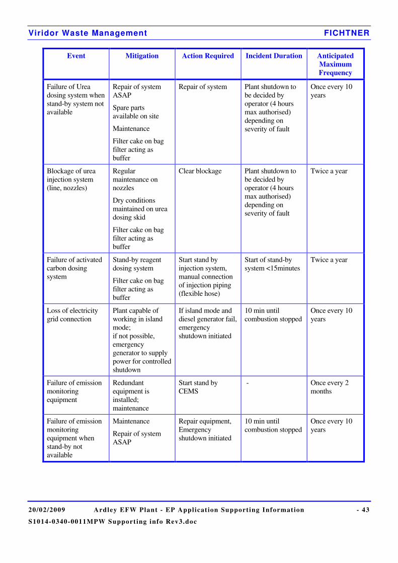
Viridor Waste Management FICHTNER
20/02/2009 Ardley EFW Plant - EP Applicat ion Supporting Information - 43
S1014-0340-0011MPW Support ing info Rev3.doc
Event Mitigation Action Required Incident Duration Anticipated Maximum Frequency
Failure of Urea dosing system when stand-by system not available
Repair of system ASAP
Spare parts available on site
Maintenance
Filter cake on bag filter acting as buffer
Repair of system Plant shutdown to be decided by operator (4 hours max authorised) depending on severity of fault
Once every 10 years
Blockage of urea injection system (line, nozzles)
Regular maintenance on nozzles
Dry conditions maintained on urea dosing skid
Filter cake on bag filter acting as buffer
Clear blockage Plant shutdown to be decided by operator (4 hours max authorised) depending on severity of fault
Twice a year
Failure of activated carbon dosing system
Stand-by reagent dosing system
Filter cake on bag filter acting as buffer
Start stand by injection system, manual connection of injection piping (flexible hose)
Start of stand-by system <15minutes
Twice a year
Loss of electricity grid connection
Plant capable of working in island mode; if not possible, emergency generator to supply power for controlled shutdown
If island mode and diesel generator fail, emergency shutdown initiated
10 min until combustion stopped
Once every 10 years
Failure of emission monitoring equipment
Redundant equipment is installed; maintenance
Start stand by CEMS
- Once every 2 months
Failure of emission monitoring equipment when stand-by not available
Maintenance
Repair of system ASAP
Repair equipment, Emergency shutdown initiated
10 min until combustion stopped
Once every 10 years

Viridor Waste Management FICHTNER
20/02/2009 Ardley EFW Plant - EP Applicat ion Supporting Information - 44
S1014-0340-0011MPW Support ing info Rev3.doc
Event Mitigation Action Required Incident Duration Anticipated Maximum Frequency
Failure of emission reporting equipment
Redundant equipment is installed; maintenance,
Automatic change-over to standby system
- Twice a year
Failure of emission reporting equipment and stand-by not available
Maintenance
Repair of system ASAP
Repair equipment, Emergency shutdown initiated
10 min until combustion stopped
Once every 10 years
Burner not starting as needed when 2 second temperature drops below 850C
Maintenance of burner
Weekly test of burner
Emergency shutdown initiated
10 min until combustion stopped
Once every 10 years
Failure of ID Fan Maintenance ; bearings vibration monitoring
Emergency shutdown initiated
10 min until combustion stopped
Once every 5 years

Viridor Waste Management FICHTNER
20/02/2009 Ardley EFW Plant - EP Applicat ion Supporting Information - 45
S1014-0340-0011MPW Support ing info Rev3.doc
2.6 Energy Efficiency
2.6.1 General
The main power plant will utilise a MSW fired steam boiler. The generated steam will supply a steam turbine generator to generate electricity.
The facility will supply electricity to the local electricity grid via a power transformer which increases the voltage to the appropriate level.
In case of failure of the electricity supply, an emergency diesel generator will be provided to safely shut down the plant and to provide an emergency supply to the rest of the facility.
In considering the energy efficiency of the facility, due account has been taken of the requirements of the Environment Agency’s Horizontal Guidance Note H2 on Energy Efficiency.
2.6.2 Basic Energy Requirements
It is estimated that the plant will generate up to 25.5 MW of electricity. About 3.3 MW of this electricity will be used within the EfW facility, 0.15 MW will be used by the ash processing plant and the remainder will be exported to the National Grid. It should be noted that the bottom ash processing plant reduces the exported power of the facility, but if the ash processing were carried out offsite, this power would be drawn from the national grid. The result is that the EfW plant appears less efficient than it would if the ash were processed offsite. However, when national grid transmission losses are considered, the onsite ash processing plant represents the most energy efficient solution.
The most significant electrical consumers are anticipated to be the following:
• Combustion Air Fans;
• Induced Draft Fans;
• Boiler feed water and cooling water pumps;
• Air cooled condenser fans
• Air compressors;
• MSW loading systems and ash and residue conveying systems.
• Offices and ancillary rooms
The facility will be designed with careful attention being paid to all normal energy efficiency design features, such as high efficiency motors, high standards of cladding and insulation etc.
The plant will be designed to achieve a high thermal efficiency. In particular: • The boilers will be equipped with economisers and super-heaters to optimise thermal
cycle efficiency without prejudicing boiler tube life, having regard for the nature of the MSW that is being burnt;
• Unnecessary releases of steam and hot water will be avoided, to avoid the loss of boiler water treatment chemicals and the heat contained within the steam and water;

Viridor Waste Management FICHTNER
20/02/2009 Ardley EFW Plant - EP Applicat ion Supporting Information - 46
S1014-0340-0011MPW Support ing info Rev3.doc
• Low grade heat will be used to preheat combustion air; • Steady operation will be maintained where necessary by using auxiliary fuel firing; • Boiler heat exchange surfaces will be cleaned on a regular basis to ensure efficient heat
recovery; • A secondary low pressure economiser, used as a condensate reheater, will recover heat
downstream the main boiler to cool down the flue gas at the right temperature for lime injection.
Due consideration will be given to the recommendations given in the Sector Guidance Note.
2.6.2.1 Operating and Maintenance Procedures
The O&M procedures will include the following aspects:
• Good maintenance and housekeeping techniques and regimes across the whole plant;
• Plant Condition Monitoring carried out on a regular basis, to ensure, amongst other things, that motors are operating efficiently, insulation and cladding are not damaged and that there are no significant leaks;
• Operators trained in energy awareness and encouraged to identify opportunities for energy efficiency improvements.
2.6.2.2 Energy Efficiency Measures
An energy efficiency plan will be built into the operation and maintenance procedures of the plant ensuring maximum, practical, sustainable, safe and controllable electricity generation. This plan will be reviewed regularly as part of the ISO14001 process.
During normal operation, procedures will be reviewed and amended, where necessary, to include improvements in efficiency as and when proven new equipment and operating techniques become available. These are assessed on the implementation cost compared with the anticipated benefits.
Viridor Waste Management FICHTNER
20/02/2009 Ardley EFW Plant - EP Applicat ion Supporting Information - 47
S1014-0340-0011MPW Support ing info Rev3.doc
2.6.3 Further Energy Efficiency Requirements
The plant will not be subject to a Climate Change Levy agreement, although the electricity generated will be partially exempt from the levy.
Under the Waste Incineration Directive, heat should be recovered as far as practicable. In order to demonstrate this, the following points should be noted:
1) The boiler will operate with superheated steam at a pressure of around 60 bar-a and a temperature of at least 400°C. Higher steam temperatures would lead to improved steam cycle efficiency, but would also potentially lead to more corrosion of the superheater tubes. The selected steam temperature represents a balance between maximum efficiency and increased corrosion risk.
2) As discussed earlier, the flue gas treatment system will be based on the dry injection of lime, rather than the injection of a wet slurry. The disadvantage of injecting a slurry is that the water in the slurry evaporates, absorbing energy. This means that the flue gas temperature entering the flue gas treatment system has to be higher, so that temperature of the flue gases reacting with the lime is maintained at around 140°C. With a dry system, the flue gases can be cooled to 140°C by extracting the energy into the condensate water, improving the efficiency of the heat recovery.
3) The possibility of exporting heat as well as power has been fully assessed in a study which can be found in the Heat Plan in Annex 6. There are several potential future heat users in the vicinity such as the local horticultural industry and the proposed new settlement at Upper Heyford. However, there are a number of major hurdles to overcome such as the cost and difficulty of setting up the appropriate infrastructure to supply potential interested parties with heat. This would require significant support and incentives from the local authority to develop the heat network. The steam turbine will therefore be designed with pass-outs to allow process steam to be extracted if and when it is required. This steam could also be used directly by other on site processes, or used to heat hot water for space heating purposes. The use of such a system allows the plant to generate only electricity (during warm weather or when process steam is not needed) or to produce a mixture of electricity and heat.
At the design point of 38.4 tph and a net calorific value of 9.2 MJ/kg, the plant will be guaranteed to generate at least 25.5 MWe. This will mean that it will meet the definition of an R1 recovery process under the draft Waste Framework Directive, as shown in the calculation below.
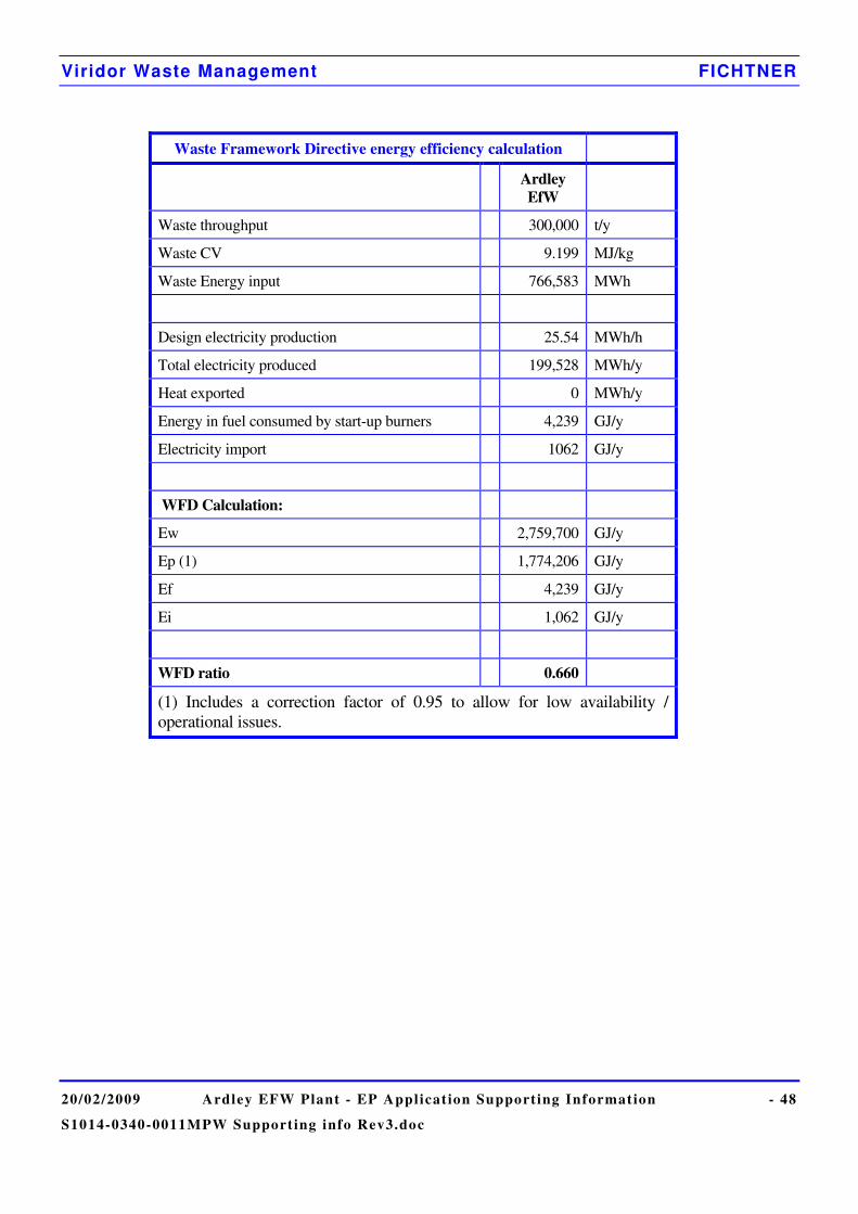
Viridor Waste Management FICHTNER
20/02/2009 Ardley EFW Plant - EP Applicat ion Supporting Information - 48
S1014-0340-0011MPW Support ing info Rev3.doc
Waste Framework Directive energy efficiency calculation
Ardley EfW
Waste throughput 300,000 t/y
Waste CV 9.199 MJ/kg
Waste Energy input 766,583 MWh
Design electricity production 25.54 MWh/h
Total electricity produced 199,528 MWh/y
Heat exported 0 MWh/y
Energy in fuel consumed by start-up burners 4,239 GJ/y
Electricity import 1062 GJ/y
WFD Calculation:
Ew 2,759,700 GJ/y
Ep (1) 1,774,206 GJ/y
Ef 4,239 GJ/y
Ei 1,062 GJ/y
WFD ratio 0.660
(1) Includes a correction factor of 0.95 to allow for low availability / operational issues.
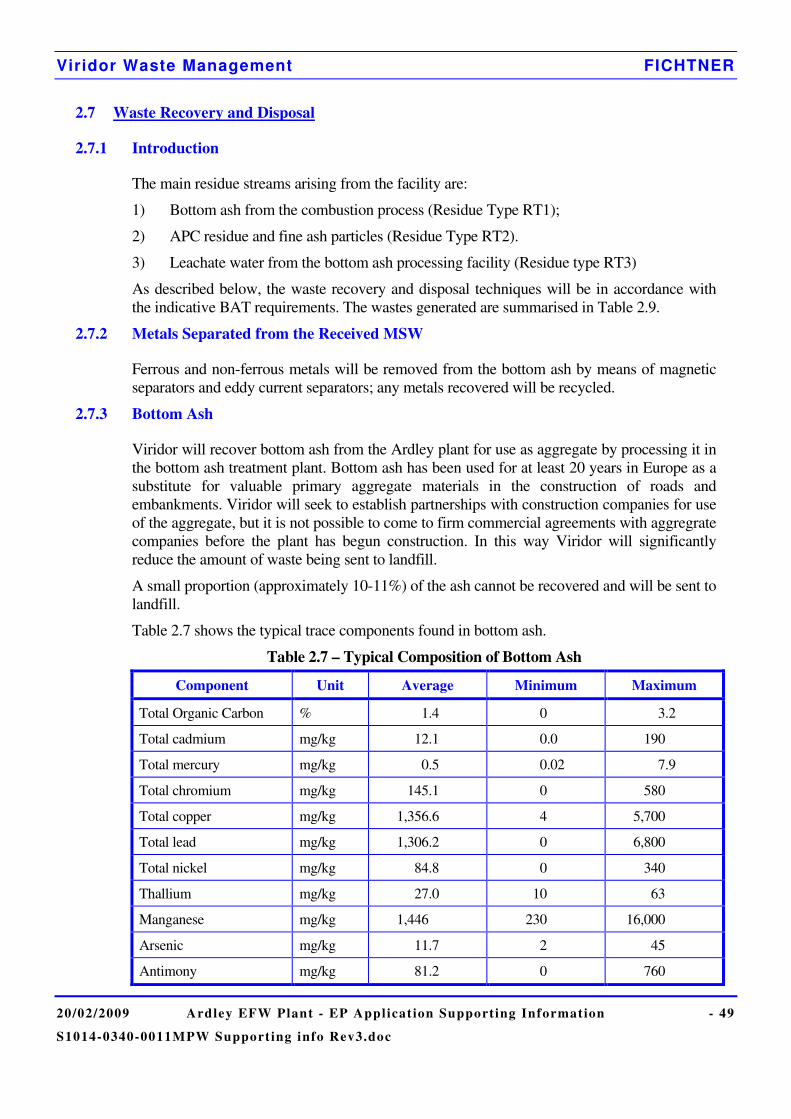
Viridor Waste Management FICHTNER
20/02/2009 Ardley EFW Plant - EP Applicat ion Supporting Information - 49
S1014-0340-0011MPW Support ing info Rev3.doc
2.7 Waste Recovery and Disposal
2.7.1 Introduction
The main residue streams arising from the facility are:
1) Bottom ash from the combustion process (Residue Type RT1);
2) APC residue and fine ash particles (Residue Type RT2).
3) Leachate water from the bottom ash processing facility (Residue type RT3)
As described below, the waste recovery and disposal techniques will be in accordance with the indicative BAT requirements. The wastes generated are summarised in Table 2.9.
2.7.2 Metals Separated from the Received MSW
Ferrous and non-ferrous metals will be removed from the bottom ash by means of magnetic separators and eddy current separators; any metals recovered will be recycled.
2.7.3 Bottom Ash
Viridor will recover bottom ash from the Ardley plant for use as aggregate by processing it in the bottom ash treatment plant. Bottom ash has been used for at least 20 years in Europe as a substitute for valuable primary aggregate materials in the construction of roads and embankments. Viridor will seek to establish partnerships with construction companies for use of the aggregate, but it is not possible to come to firm commercial agreements with aggregrate companies before the plant has begun construction. In this way Viridor will significantly reduce the amount of waste being sent to landfill.
A small proportion (approximately 10-11%) of the ash cannot be recovered and will be sent to landfill.
Table 2.7 shows the typical trace components found in bottom ash.
Table 2.7 – Typical Composition of Bottom Ash
Component Unit Average Minimum Maximum
Total Organic Carbon % 1.4 0 3.2
Total cadmium mg/kg 12.1 0.0 190
Total mercury mg/kg 0.5 0.02 7.9
Total chromium mg/kg 145.1 0 580
Total copper mg/kg 1,356.6 4 5,700
Total lead mg/kg 1,306.2 0 6,800
Total nickel mg/kg 84.8 0 340
Thallium mg/kg 27.0 10 63
Manganese mg/kg 1,446 230 16,000
Arsenic mg/kg 11.7 2 45
Antimony mg/kg 81.2 0 760

Viridor Waste Management FICHTNER
20/02/2009 Ardley EFW Plant - EP Applicat ion Supporting Information - 50
S1014-0340-0011MPW Support ing info Rev3.doc
Component Unit Average Minimum Maximum
Cobalt mg/kg 17 6.0 41.0
Vanadium mg/kg 45.1 10.0 120.0
Zinc mg/kg 2,688.5 3.6 13,000.0
Tin mg/kg 121.0 23 220
Dioxin/Furan (Total) ng/kg 529.9 0.0 2,500
Dioxin/Furan (ITEQ) ng/kg 9.4 0.0 55
2.7.4 Air Pollution Control Residues
APC residues are predominantly composed of calcium as hydroxide, carbonate, sulphate and chloride/hydroxide complexes. Typical major element concentration ranges for the UK residues are as follows:
30-36% w/w Calcium
12-15% w/w Chlorine
8-10% w/w Carbonate (as C)
3-4% w/w Sulphate (as S).
Silicon, Aluminium, Iron, Magnesium and Fluorine are also present in addition to traces of dioxins and the following heavy metals: Zinc, Lead, Manganese, Copper, Chromium, Cadmium, Mercury, and Arsenic.
It may be possible to send the residue to an effluent treatment contractor, to be used to neutralise acids and similar materials. Using the residues in this way avoids the use of primary materials. If this option is not practicable then it will be sent to a secure landfill for disposal as a hazardous waste. The residue is collected in the ash silo and transported off site by sealed road tanker thereby minimising the chance of spillage and dust emissions.
2.7.5 Bottom Ash Leachate
Leachate from the bottom ash facility will be reused on the ash piles where possible, but the excess will be sent to the existing Ardley landfill Leachate Treatment Plant. The exact concentration of contaminants in the leachate is not known but typical components from an existing UK bottom ash processing facility are shown in Table 2.8.
Table 2.8 – Typical Composition of Leachate
Component Unit Typical range
pH 7 - 9
Suspended Solids mg / l 50 – 300
Oil and Grease mg / l 20 - 190
Chemical Oxygen Demand (COD) mg / l 1000 - 2000
Biochemical Oxygen Demand (BOD) mg / l 150 - 500
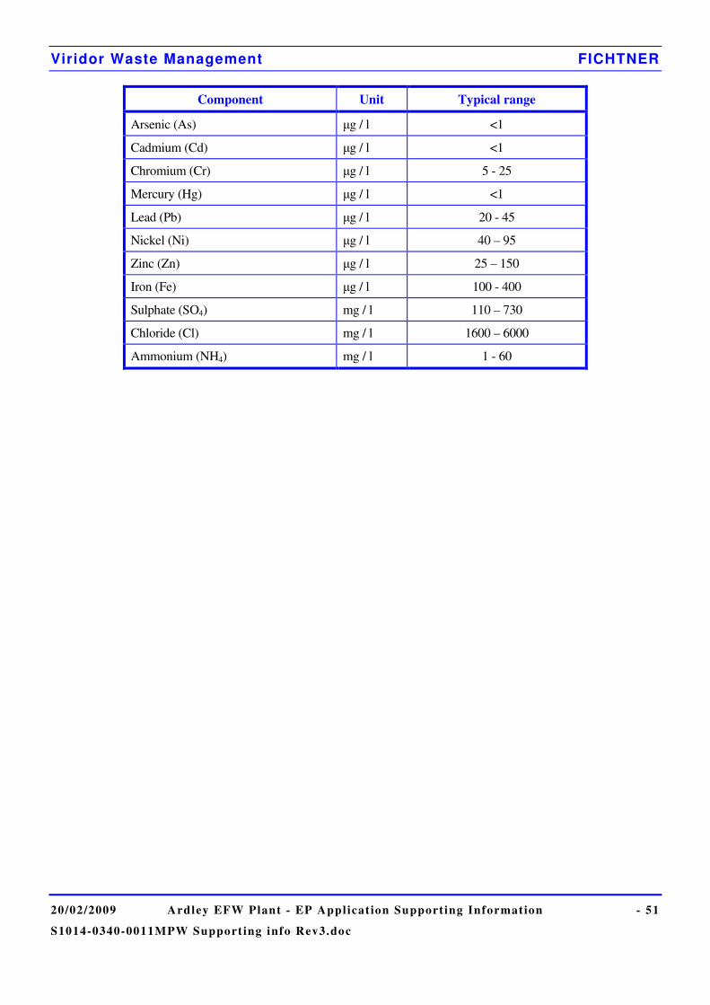
Viridor Waste Management FICHTNER
20/02/2009 Ardley EFW Plant - EP Applicat ion Supporting Information - 51
S1014-0340-0011MPW Support ing info Rev3.doc
Component Unit Typical range
Arsenic (As) �g / l <1
Cadmium (Cd) �g / l <1
Chromium (Cr) �g / l 5 - 25
Mercury (Hg) �g / l <1
Lead (Pb) �g / l 20 - 45
Nickel (Ni) �g / l 40 – 95
Zinc (Zn) �g / l 25 – 150
Iron (Fe) �g / l 100 - 400
Sulphate (SO4) mg / l 110 – 730
Chloride (Cl) mg / l 1600 – 6000
Ammonium (NH4) mg / l 1 - 60
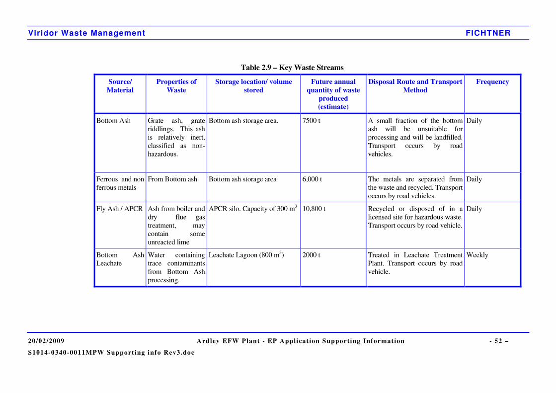
Viridor Waste Management FICHTNER
20/02/2009 Ardley EFW Plant - EP Applicat ion Supporting Information - 52 –
S1014-0340-0011MPW Support ing info Rev3.doc
Table 2.9 – Key Waste Streams
Source/ Material
Properties of Waste
Storage location/ volume stored
Future annual quantity of waste
produced (estimate)
Disposal Route and Transport Method
Frequency
Bottom Ash Grate ash, grate riddlings. This ash is relatively inert, classified as non-hazardous.
Bottom ash storage area. 7500 t A small fraction of the bottom ash will be unsuitable for processing and will be landfilled. Transport occurs by road vehicles.
Daily
Ferrous and non ferrous metals
From Bottom ash Bottom ash storage area 6,000 t The metals are separated from the waste and recycled. Transport occurs by road vehicles.
Daily
Fly Ash / APCR Ash from boiler and dry flue gas treatment, may contain some unreacted lime
APCR silo. Capacity of 300 m3 10,800 t Recycled or disposed of in a licensed site for hazardous waste. Transport occurs by road vehicle.
Daily
Bottom Ash Leachate
Water containing trace contaminants from Bottom Ash processing.
Leachate Lagoon (800 m3) 2000 t Treated in Leachate Treatment Plant. Transport occurs by road vehicle.
Weekly
Viridor Waste Management FICHTNER
20/02/2009 Ardley EFW Plant - EP Applicat ion Supporting Information - 53 –
S1014-0340-0011MPW Support ing info Rev3.doc
2.8 Management
2.8.1 Introduction
Viridor demonstrates environmental and social responsibility by operating all facilities and services to the highest environmental, health and safety and professional standards. Viridor has developed and implemented a documented Business Management System (BMS) which combines Environmental, Quality and Occupational Health and Safety management procedures.
The company BMS applies to all operational facilities and is maintained to meet the requirements of the BS EN ISO 14001:2004 Environmental Management System Standard, the BS EN ISO 9001:2000 Quality Management System Standard and the BS OHSAS 18001:2007 Occupational Health and Safety Management System Standard.
Viridor will develop a management structure and a BMS accredited to ISO 14001, ISO 9001 and OHSAS 18001 for the Ardley EfW plant. The BMS is part of the facility’s overall management system that establishes an organisational structure, responsibilities, practices, procedures and resources for achieving, reviewing and maintaining the company’s commitment to environmental protection.
2.8.2 Management Systems
2.8.2.1 Scope and Structure
The scope of Viridor’s certification is:
“Activities associated with operational and support services of various waste management facilities, including recycling, estates management, environment control, legal/planning and engineering. The collection and transportation of wastes and recyclates. The operation and maintenance of waste to energy conversion plants and support operations on the control of landfill gas.”
Where applicable, documented procedures detail specifically how each activity is to be controlled. It can be seen that the BMS already incorporates the activities which would be carried out at Ardley EfW. It would be adapted to incorporate the site-specific procedures for this facility.
2.8.2.2 General Requirements
The objectives and scope of the BMS ensure that Viridor meets the requirements by:
• identifying, documenting and implementing standard procedures for use throughout Viridor;
• determining a procedural hierarchy with regard to the sequence and interaction of the relevant processes;
• giving adequate responsibility, authority and resources to management necessary to support the operation of the BMS;
• establishing criteria to assess the effectiveness of the procedures;
Viridor Waste Management FICHTNER
20/02/2009 Ardley EFW Plant - EP Applicat ion Supporting Information - 54 –
S1014-0340-0011MPW Support ing info Rev3.doc
• monitoring, measuring and analysing the procedures for their effectiveness; and
• implementing actions necessary to achieve planned results and continual improvements of these processes.
2.8.3 Personnel
Operation and maintenance of the plant will be undertaken by the applicant’s own staff. Sufficient numbers of staff, in various grades, will be provided to manage, operate and maintain the plant on a continuous basis, 7 days per week throughout the year. The plant will be managed, operated and maintained by experienced managers, boiler operators and maintenance staff.
The key environmental management responsibilities will be allocated as described below
The General Manager will have overall responsibility for management of the site and compliance with the operating permit. He or she will also be responsible for waste management and scheduling. The general manager will have extensive experience relevant to his responsibilities.
The Operations Manager will have day-to-day responsibility for the operation of the plant, to ensure that the plant is operated in accordance with the permit and that the environmental impact of the plant’s operations is minimised. In this context, he or she will be responsible for designing and implementing operating procedures which incorporate environmental aspects.
The Compliance Manager will be responsible for the development and management of the Environmental Management System, for the monitoring of authorised releases and for interaction with the Environment Agency.
The Engineering Manager will be responsible for the management of maintenance activities, for maintenance planning and for ensuring that the plant continues to operate in accordance with its design.
2.8.4 Competence, Training and Awareness
Through documented procedures, Viridor aims to ensure that any persons performing tasks for it or on its behalf that have the potential to cause significant impact on the environment are competent on the basis of appropriate education, training or experience, and will retain associated records.
Viridor has committed to make employees aware of:
• the importance of conformity with policies and procedures required by the BMS;
• potentially significant environmental aspects associated with their work;
• their roles and responsibilities in achieving conformity with the requirements of the BMS, including emergency preparedness and response requirements;
• the relevance and importance of their activities and how they contribute to the achievement of the environmental and quality objectives; and
• the potential consequences of the departure from specified procedures.
Viridor Waste Management FICHTNER
20/02/2009 Ardley EFW Plant - EP Applicat ion Supporting Information - 55 –
S1014-0340-0011MPW Support ing info Rev3.doc
2.8.4.1 Competence
Minimum role competency requirements will be identified by the Line Manager and/or HR Department and satisfied through the recruitment process. All roles are documented by the HR Department with the specific job requirements defined in “Principal Responsibilities” and “Key Job Elements”. The expected candidate competency requirements are broken down into four areas - Knowledge, Skills, Experience and Qualifications with essential and desirable competencies identified in each area.
2.8.4.2 Induction and Awareness
Staff induction programmes are location-specific and will include, as a minimum, the induction of the following:
• the Environmental Policy;
• the Quality Policy; and
• the BMS Awareness Training.
2.8.4.3 Training
Ongoing staff training needs will be identified and progress monitored by line management as part of the employee appraisal system. Once identified, the training needs of employees will be addressed in a number of ways, including:
• on-the-job training;
• coaching and mentoring;
• internal training and development events; and
• external training courses/ events.
Training records will be maintained on site. Viridor will comply with industry standards or codes of practice for training (eg WAMITAB), where they exist.
Viridor Waste Management FICHTNER
20/02/2009 Ardley EFW Plant - EP Applicat ion Supporting Information - 56 –
S1014-0340-0011MPW Support ing info Rev3.doc
2.9 Closure
2.9.1 Introduction
The facility is designed for an operational life of approximately 30 years, but its actual operational lifetime is dependent on a number of factors including:
• The continued supply of waste fuels; and
• The development of alternative methods competing for the same waste fuels.
When the facility has reached the end of its operational life, it may be redeveloped for extended use or demolished as part of a redevelopment scheme and the site cleared and left in a fit-for-use condition.
2.9.2 General
At the end of the economic life of the plant, the development site and buildings may be redeveloped for extended use or form part of an appropriate landscape restoration plan. The responsibility for this may well rest with other parties if the facility is sold. However, the Applicant recognises the need to ensure that the design, the operation and the maintenance procedures facilitate decommissioning in a safe manner without risk of pollution, contamination or excessive disturbance to noise, dust, odour, ground and water courses.
To achieve this aim a site closure plan will be prepared. It is anticipated that the closure plan will include the information listed below.
2.9.3 Site Closure Plan
The following is a summary of the measures to be considered within the site closure plan to ensure the objective of safe and clean decommissioning.
2.9.3.1 General Requirements
• Underground tanks and pipework to be avoided except for supply and discharge utilities such as towns water, sewerage lines and gas supply;
• Safe removal of all chemical and hazardous materials;
• Adequate provision for drainage, vessel cleaning and dismantling of pipework;
• Disassembly and containment procedures for insulation, materials handling equipment, material extraction equipment, fabric filters and other filtration equipment without significant leakage, spillage, dust or hazard;
• The use of recyclable materials where possible;
• Methodology for the removal/decommissioning of components and structures to minimise the exposure of noise, disturbance, dust and odours and for the protection of surface and groundwater;
• Soil sampling and testing of sensitive areas to ensure the minimum disturbance (sensitive areas to be selected with reference to the initial site report).
Viridor Waste Management FICHTNER
20/02/2009 Ardley EFW Plant - EP Applicat ion Supporting Information - 57 –
S1014-0340-0011MPW Support ing info Rev3.doc
2.9.3.2 Specific Details
• A list of recyclable materials/components and current potential outlet sources;
• A list of materials/components not suitable for recycle and potential outlet sources;
• A list of materials to go to landfill with current recognised analysis, where appropriate;
• A list of all chemicals and hazardous materials, location and current containment methods;
• A Bill of Materials detailing total known quantities of items throughout the site such as:
• Steelwork;
• Plastics;
• Cables;
• Concrete and Civils Materials;
• Oils;
• Chemicals;
• Consumables;
• Contained Water and Effluents;
• Bottom Ash and APC Residues.
2.9.3.3 Disposal Routes
Each of the items listed within the Bill of Materials will have a recognised or special route for disposal identified; e.g. Landfill by a licensed contractor, disposal by high sided, fully sheeted road vehicle or for sale to a scrap metal dealer, disposal by skip/fully enclosed container, dealer to collect and disposal by container.
Viridor Waste Management FICHTNER
20/02/2009 Ardley EFW Plant - EP Applicat ion Supporting Information - 58 –
S1014-0340-0011MPW Support ing info Rev3.doc
3 WASTE INCINERATION QUESTIONS
The guidance notes on Part B of the Application form states that, in order to respond to questions 4 to 6 in Appendix 7, the application should include all of the details specified in Technical Guidance Note S5.01, section 2, ‘Key Issues’, sub-heading ‘European Legislation and your application for an EP permit’. The revised version of this guidance note has not yet been formally issued, but the Environment Agency has provided a draft copy. In the table below, we have listed all of the questions asked in the relevant section and explained where the answer can be found.
Question Additional Information Required Location of additional
information in application
1 Does the installation contain more than one incineration line? Identify with a brief reference (e.g. L1, L2 etc) and provide a brief description (e.g. fixed hearth, chain grate) of each line.
Application 2b, Supporting information 1.3
2 State the maximum design capacity (in tonnes/hour) for waste incineration for each line, and the maximum total incineration capacity (in tonnes/hour) of the plant.
Application part B 5d, Supporting information 1.3
3 Are any of the wastes you treat hazardous waste for WID purposes? No
4 For each line, provide the following information: /
a Is the operating temperature of the plant, after the last injection of combustion air, 1100°C for hazardous waste with greater than 1% halogenated hydrocarbons expressed as chlorine, or 850°C for all other wastes?
Yes
b If the operating temperature is below 1100°C for incineration of hazardous waste with greater than 1% halogenated hydrocarbons expressed as chlorine, or below 850°C for all other wastes, you must request a derogation under WID Article 6(4) with a justification that the operation will not lead to the production of more residues or residues with a higher content of organic pollutants than could be expected if operation was according to the WID conditions.
n/a
c State the residence time of gas at the operating temperature given above. Is it less than 2 seconds?
No
d Where the residence time is less than 2 seconds, you must request a derogation under WID Article 6(4) with a justification that the operation will not lead to the production of more residues or residues with a higher content of organic pollutants than could be expected if operation was according to the WID conditions.
n/a
e Describe the technique that will be used to verify the gas residence time and the minimum operating temperature given, both under normal operation and under the most unfavourable operating conditions anticipated, in accordance with the WID Article 6 (4).
Supporting information 2.5.1.1
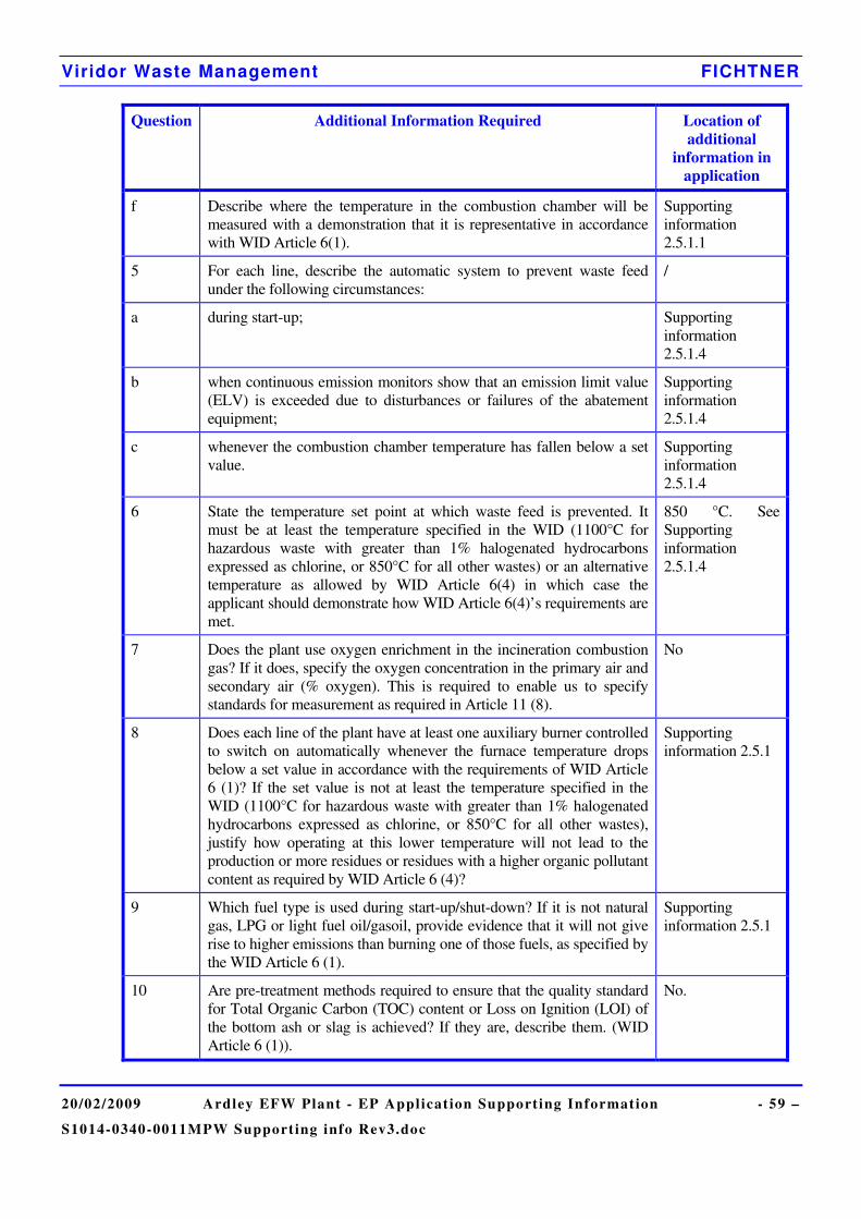
Viridor Waste Management FICHTNER
20/02/2009 Ardley EFW Plant - EP Applicat ion Supporting Information - 59 –
S1014-0340-0011MPW Support ing info Rev3.doc
Question Additional Information Required Location of additional
information in application
f Describe where the temperature in the combustion chamber will be measured with a demonstration that it is representative in accordance with WID Article 6(1).
Supporting information 2.5.1.1
5 For each line, describe the automatic system to prevent waste feed under the following circumstances:
/
a during start-up; Supporting information 2.5.1.4
b when continuous emission monitors show that an emission limit value (ELV) is exceeded due to disturbances or failures of the abatement equipment;
Supporting information 2.5.1.4
c whenever the combustion chamber temperature has fallen below a set value.
Supporting information 2.5.1.4
6 State the temperature set point at which waste feed is prevented. It must be at least the temperature specified in the WID (1100°C for hazardous waste with greater than 1% halogenated hydrocarbons expressed as chlorine, or 850°C for all other wastes) or an alternative temperature as allowed by WID Article 6(4) in which case the applicant should demonstrate how WID Article 6(4)’s requirements are met.
850 °C. See Supporting information 2.5.1.4
7 Does the plant use oxygen enrichment in the incineration combustion gas? If it does, specify the oxygen concentration in the primary air and secondary air (% oxygen). This is required to enable us to specify standards for measurement as required in Article 11 (8).
No
8 Does each line of the plant have at least one auxiliary burner controlled to switch on automatically whenever the furnace temperature drops below a set value in accordance with the requirements of WID Article 6 (1)? If the set value is not at least the temperature specified in the WID (1100°C for hazardous waste with greater than 1% halogenated hydrocarbons expressed as chlorine, or 850°C for all other wastes), justify how operating at this lower temperature will not lead to the production or more residues or residues with a higher organic pollutant content as required by WID Article 6 (4)?
Supporting information 2.5.1
9 Which fuel type is used during start-up/shut-down? If it is not natural gas, LPG or light fuel oil/gasoil, provide evidence that it will not give rise to higher emissions than burning one of those fuels, as specified by the WID Article 6 (1).
Supporting information 2.5.1
10 Are pre-treatment methods required to ensure that the quality standard for Total Organic Carbon (TOC) content or Loss on Ignition (LOI) of the bottom ash or slag is achieved? If they are, describe them. (WID Article 6 (1)).
No.
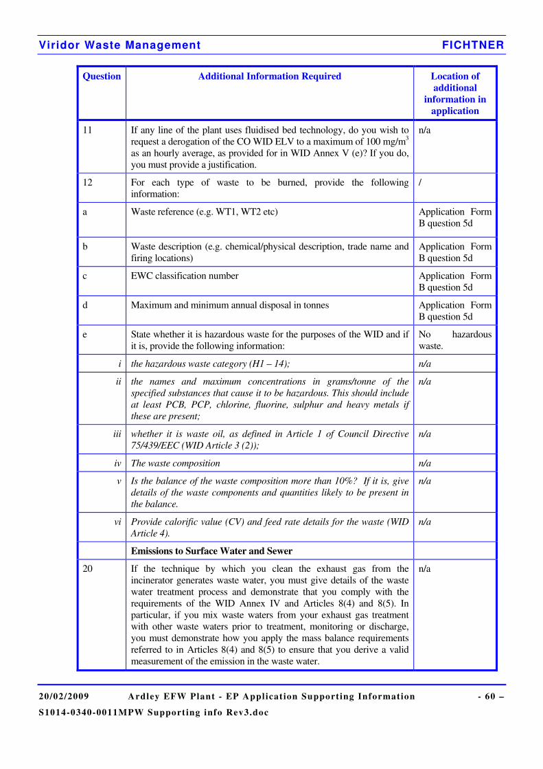
Viridor Waste Management FICHTNER
20/02/2009 Ardley EFW Plant - EP Applicat ion Supporting Information - 60 –
S1014-0340-0011MPW Support ing info Rev3.doc
Question Additional Information Required Location of additional
information in application
11 If any line of the plant uses fluidised bed technology, do you wish to request a derogation of the CO WID ELV to a maximum of 100 mg/m3 as an hourly average, as provided for in WID Annex V (e)? If you do, you must provide a justification.
n/a
12 For each type of waste to be burned, provide the following information:
/
a Waste reference (e.g. WT1, WT2 etc)
Application Form B question 5d
b Waste description (e.g. chemical/physical description, trade name and firing locations)
Application Form B question 5d
c EWC classification number Application Form B question 5d
d Maximum and minimum annual disposal in tonnes Application Form B question 5d
e State whether it is hazardous waste for the purposes of the WID and if it is, provide the following information:
No hazardous waste.
i the hazardous waste category (H1 – 14); n/a
ii the names and maximum concentrations in grams/tonne of the specified substances that cause it to be hazardous. This should include at least PCB, PCP, chlorine, fluorine, sulphur and heavy metals if these are present;
n/a
iii whether it is waste oil, as defined in Article 1 of Council Directive 75/439/EEC (WID Article 3 (2));
n/a
iv The waste composition n/a
v Is the balance of the waste composition more than 10%? If it is, give details of the waste components and quantities likely to be present in the balance.
n/a
vi Provide calorific value (CV) and feed rate details for the waste (WID Article 4).
n/a
Emissions to Surface Water and Sewer
20 If the technique by which you clean the exhaust gas from the incinerator generates waste water, you must give details of the waste water treatment process and demonstrate that you comply with the requirements of the WID Annex IV and Articles 8(4) and 8(5). In particular, if you mix waste waters from your exhaust gas treatment with other waste waters prior to treatment, monitoring or discharge, you must demonstrate how you apply the mass balance requirements referred to in Articles 8(4) and 8(5) to ensure that you derive a valid measurement of the emission in the waste water.
n/a
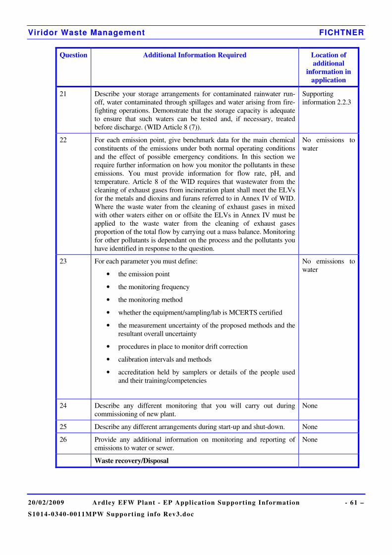
Viridor Waste Management FICHTNER
20/02/2009 Ardley EFW Plant - EP Applicat ion Supporting Information - 61 –
S1014-0340-0011MPW Support ing info Rev3.doc
Question Additional Information Required Location of additional
information in application
21 Describe your storage arrangements for contaminated rainwater run-off, water contaminated through spillages and water arising from fire-fighting operations. Demonstrate that the storage capacity is adequate to ensure that such waters can be tested and, if necessary, treated before discharge. (WID Article 8 (7)).
Supporting information 2.2.3
22 For each emission point, give benchmark data for the main chemical constituents of the emissions under both normal operating conditions and the effect of possible emergency conditions. In this section we require further information on how you monitor the pollutants in these emissions. You must provide information for flow rate, pH, and temperature. Article 8 of the WID requires that wastewater from the cleaning of exhaust gases from incineration plant shall meet the ELVs for the metals and dioxins and furans referred to in Annex IV of WID. Where the waste water from the cleaning of exhaust gases in mixed with other waters either on or offsite the ELVs in Annex IV must be applied to the waste water from the cleaning of exhaust gases proportion of the total flow by carrying out a mass balance. Monitoring for other pollutants is dependant on the process and the pollutants you have identified in response to the question.
No emissions to water
23 For each parameter you must define:
• the emission point
• the monitoring frequency
• the monitoring method
• whether the equipment/sampling/lab is MCERTS certified
• the measurement uncertainty of the proposed methods and the resultant overall uncertainty
• procedures in place to monitor drift correction
• calibration intervals and methods
• accreditation held by samplers or details of the people used and their training/competencies
No emissions to water
24 Describe any different monitoring that you will carry out during commissioning of new plant.
None
25 Describe any different arrangements during start-up and shut-down. None
26 Provide any additional information on monitoring and reporting of emissions to water or sewer.
None
Waste recovery/Disposal

Viridor Waste Management FICHTNER
20/02/2009 Ardley EFW Plant - EP Applicat ion Supporting Information - 62 –
S1014-0340-0011MPW Support ing info Rev3.doc
Question Additional Information Required Location of additional
information in application
27 How do you deal with the residue from the incineration plant? Explain how you minimise, recover, recycle and dispose of it.
Supporting information 2.1.5 and 2.7.
CEMS Performance
28 How do you intend to manage the continuous measurement system to satisfy WID Article 11 (11)? WID Article 11 allows a valid daily average to be obtained only if no more than
• 5 half-hourly averages, and
• 10 daily averages per calendar year
during the day are discarded due to malfunction or maintenance of the continuous measurement system.
Give details of how calibration, maintenance and failure of the continuous measurement system will be managed in order to satisfy these limitations. If necessary distinguish between different incineration lines.
Supporting information 2.3.1.1
29 Give details of how you define when start-up ends and shut-down begins. Describe any different arrangements for monitoring during start up or shut down. Note that the emission limit values specified for compliance with the WID do not apply during start-up or shut-down when no waste is being burned. Explain how you will integrate these periods into the emissions monitoring system in such a way that the reportable averages are calculated between these times, but the raw monitoring data remains available for inspection. (WID Article 11(11)). If necessary distinguish between different incineration lines.
Supporting information 2.3.1.1
30 Describe each type of unavoidable stoppage, disturbance or failure of the abatement plant or continuous emission monitoring system during which plant operation will continue. State the maximum time anticipated before shut-down is initiated for each of these types of unavoidable stoppage.
Supporting Information 2.5.2
31 Will the values of the 95% confidence intervals of a single measured value of the daily emission limit value, exceed the percentages of the emission limit values required by WID Article 11(11) and Annex III. point 3, as tabulated below? (We will accept that MCERTS certified instruments satisfy these quality requirements).
Supporting information 2.3.1.1
32 Describe the monitoring of process variables, using the format tabulated below. For emissions to air, include at least the arrangements for monitoring oxygen content, temperature, pressure and water vapour content at the points where emissions to air will be monitored (WID Article 11 (7)). For emissions of waste water from the cleaning of exhaust gases include at least the arrangements for monitoring pH, temperature and flow rate (WID Article 8 (6)).
Supporting information 2.3.1.1 and 2.3.3
Heat Recovery
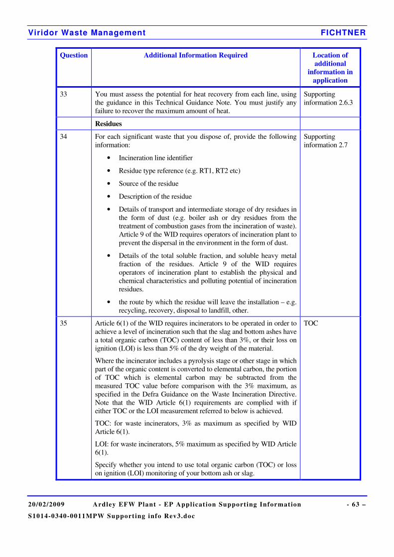
Viridor Waste Management FICHTNER
20/02/2009 Ardley EFW Plant - EP Applicat ion Supporting Information - 63 –
S1014-0340-0011MPW Support ing info Rev3.doc
Question Additional Information Required Location of additional
information in application
33 You must assess the potential for heat recovery from each line, using the guidance in this Technical Guidance Note. You must justify any failure to recover the maximum amount of heat.
Supporting information 2.6.3
Residues
34 For each significant waste that you dispose of, provide the following information:
• Incineration line identifier
• Residue type reference (e.g. RT1, RT2 etc)
• Source of the residue
• Description of the residue
• Details of transport and intermediate storage of dry residues in the form of dust (e.g. boiler ash or dry residues from the treatment of combustion gases from the incineration of waste). Article 9 of the WID requires operators of incineration plant to prevent the dispersal in the environment in the form of dust.
• Details of the total soluble fraction, and soluble heavy metal fraction of the residues. Article 9 of the WID requires operators of incineration plant to establish the physical and chemical characteristics and polluting potential of incineration residues.
• the route by which the residue will leave the installation – e.g. recycling, recovery, disposal to landfill, other.
Supporting information 2.7
35 Article 6(1) of the WID requires incinerators to be operated in order to achieve a level of incineration such that the slag and bottom ashes have a total organic carbon (TOC) content of less than 3%, or their loss on ignition (LOI) is less than 5% of the dry weight of the material.
Where the incinerator includes a pyrolysis stage or other stage in which part of the organic content is converted to elemental carbon, the portion of TOC which is elemental carbon may be subtracted from the measured TOC value before comparison with the 3% maximum, as specified in the Defra Guidance on the Waste Incineration Directive. Note that the WID Article 6(1) requirements are complied with if either TOC or the LOI measurement referred to below is achieved.
TOC: for waste incinerators, 3% as maximum as specified by WID Article 6(1).
LOI: for waste incinerators, 5% maximum as specified by WID Article 6(1).
Specify whether you intend to use total organic carbon (TOC) or loss on ignition (LOI) monitoring of your bottom ash or slag.
TOC
Viridor Waste Management FICHTNER
20/02/2009 Ardley EFW Plant - EP Applicat ion Supporting Information - 64 –
S1014-0340-0011MPW Support ing info Rev3.doc
Annex 1 Location Plan and Site Plans

Viridor Waste Management FICHTNER
20/02/2009 Ardley EFW Plant - EP Applicat ion Supporting Information - 65 –
S1014-0340-0011MPW Support ing info Rev3.doc
Annex 2 Site Condition Report
Viridor Waste Management FICHTNER
20/02/2009 Ardley EFW Plant - EP Applicat ion Supporting Information - 66 –
S1014-0340-0011MPW Support ing info Rev3.doc
Annex 3 Noise Assessment

Viridor Waste Management FICHTNER
20/02/2009 Ardley EFW Plant - EP Applicat ion Supporting Information - 67 –
S1014-0340-0011MPW Support ing info Rev3.doc
Annex 4 Environmental Risk Assessment

Viridor Waste Management FICHTNER
20/02/2009 Ardley EFW Plant - EP Applicat ion Supporting Information - 68 –
S1014-0340-0011MPW Support ing info Rev3.doc
Annex 5 Air Quality Assessment
Viridor Waste Management FICHTNER
20/02/2009 Ardley EFW Plant - EP Applicat ion Supporting Information - 69 –
S1014-0340-0011MPW Support ing info Rev3.doc
Annex 6 Heat Plan