VIRGINIA SOIL AND WATER CONSERVATION …VIRGINIA SOIL AND WATER CONSERVATION BOARD GUIDANCE DOCUMENT...
21
(DCR-VSWCB-038) (09/18) 1 VIRGINIA SOIL AND WATER CONSERVATION BOARD GUIDANCE DOCUMENT ON DAM BREAK INUNDATION ZONE MODELING AND MAPPING PROCEDURES (Approved September 7, 2016) (Revised November 16, 2017, June 28, 2018, and September 27, 2018) Summary: This guidance document specifies the procedures to be utilized by the Virginia Soil and Water Conservation Board in determining the adequacy of a dam break inundation zone analysis which includes modeling and mapping prepared by an impounding structure owner and their engineer in accordance with 4VAC50-20-54. Electronic Copy: An electronic copy of this guidance in PDF format is available on the Regulatory Town Hall under the Virginia Soil and Water Conservation Board at http://townhall.virginia.gov/L/GDocs.cfm. The study entitled "Probable Maximum Precipitation Study for Virginia (November 2015)", the PMP Evaluation Tool, the Virginia PMP 2015 Watershed Calculation Spreadsheet, and related information may be found on the Department’s website at http://www.dcr.virginia.gov/dam- safety-and-floodplains/. Contact Information: Please contact the Department of Conservation and Recreation’s Division of Dam Safety and Floodplain Management at [email protected] or by calling 804-371-6095 with any questions regarding the application of this guidance. Disclaimer: This document is provided as guidance and, as such, sets forth standard operating procedures for the Department of Conservation and Recreation in administering the Dam Safety Program on behalf of the Virginia Soil and Water Conservation Board. This guidance provides a general interpretation of the applicable Code and Regulations but is not meant to be exhaustive in nature. Each situation may differ and may require additional interpretation of the Dam Safety Act and attendant regulations. This guidance is not intended and cannot be relied on to create any rights, substantive or procedural, on the part of any person or entity. Dam Break Inundation Zone Modeling and Mapping Procedures I. Background: The Impounding Structure Regulations require an owner of a regulated dam to conduct a dam break analysis to support the appropriate hazard classification of the impounding structure in
Transcript of VIRGINIA SOIL AND WATER CONSERVATION …VIRGINIA SOIL AND WATER CONSERVATION BOARD GUIDANCE DOCUMENT...

(DCR-VSWCB-038) (09/18) 1
VIRGINIA SOIL AND WATER CONSERVATION BOARD
GUIDANCE DOCUMENT ON DAM BREAK INUNDATION
ZONE MODELING AND MAPPING PROCEDURES
(Approved September 7, 2016) (Revised November 16, 2017, June 28, 2018, and September 27, 2018)
Summary: This guidance document specifies the procedures to be utilized by the Virginia Soil and Water Conservation Board in determining the adequacy of a dam break inundation zone analysis which includes modeling and mapping prepared by an impounding structure owner and their engineer in accordance with 4VAC50-20-54. Electronic Copy: An electronic copy of this guidance in PDF format is available on the Regulatory Town Hall under the Virginia Soil and Water Conservation Board at http://townhall.virginia.gov/L/GDocs.cfm. The study entitled "Probable Maximum Precipitation Study for Virginia (November 2015)", the PMP Evaluation Tool, the Virginia PMP 2015 Watershed Calculation Spreadsheet, and related information may be found on the Department’s website at http://www.dcr.virginia.gov/dam-safety-and-floodplains/. Contact Information: Please contact the Department of Conservation and Recreation’s Division of Dam Safety and Floodplain Management at [email protected] or by calling 804-371-6095 with any questions regarding the application of this guidance. Disclaimer: This document is provided as guidance and, as such, sets forth standard operating procedures for the Department of Conservation and Recreation in administering the Dam Safety Program on behalf of the Virginia Soil and Water Conservation Board. This guidance provides a general interpretation of the applicable Code and Regulations but is not meant to be exhaustive in nature. Each situation may differ and may require additional interpretation of the Dam Safety Act and attendant regulations. This guidance is not intended and cannot be relied on to create any rights, substantive or procedural, on the part of any person or entity. Dam Break Inundation Zone Modeling and Mapping Procedures I. Background: The Impounding Structure Regulations require an owner of a regulated dam to conduct a dam break analysis to support the appropriate hazard classification of the impounding structure in

(DCR-VSWCB-038) (09/18) 2
accordance with 4VAC50-20-40 (Hazard Potential Classification of Impounding Structures). Additionally, in accordance with 4VAC50-20-54 (Dam Break Inundation Zone Mapping) of the Impounding Structure Regulations, a dam break inundation zone map shall be developed that meets the requirements of the Dam Safety Act and the Impounding Structure Regulations for regulated dams with a High, Significant or Low Hazard Potential. This guidance outlines procedures that impounding structure (dam) owners and their engineers should utilize to conduct dam break analyses as well as to produce the associated maps. II. Definitions (pursuant to § 10.1-604, 4VAC50-20-30, and 4VAC50-20-50): "Dam break inundation zone" means the area downstream of a dam that would be inundated or otherwise directly affected by the failure of a dam. "Impounding structure" or "dam" means a man-made structure, whether a dam across a watercourse or structure outside a watercourse, used or to be used to retain or store waters or other materials. The term includes: (i) all dams that are 25 feet or greater in height and that create an impoundment capacity of 15 acre-feet or greater, and (ii) all dams that are six feet or greater in height and that create an impoundment capacity of 50 acre-feet or greater. The term "impounding structure" shall not include: (a) dams licensed by the State Corporation Commission that are subject to a safety inspection program; (b) dams owned or licensed by the United States government; (c) dams operated primarily for agricultural purposes which are less than 25 feet in height or which create a maximum impoundment capacity smaller than 100 acre feet; (d) water or silt retaining dams approved pursuant to § 45.1-222 or 45.1-225.1 of the Code of Virginia; or (e) obstructions in a canal used to raise or lower water. “PMF” means the Probable Maximum Flood and represents the flood that might be expected from the most severe combination of critical meteorologic and hydrologic conditions that are reasonably possible in the region. The PMF shall be calculated from the probable maximum precipitation (PMP) derived from the Probable Maximum Precipitation Study for Virginia (and associated PMP Evaluation Tool and Database) (November 2015). The owner's engineer must develop PMF hydrographs for 6-, 12-, and 24-hour durations. The hydrograph that creates the largest peak outflow is to be used to determine capacity for non-failure and failure analysis. Present and planned land-use conditions shall be considered in determining the runoff characteristics of the drainage area. “SDF” means the Spillway Design Flood and represents the largest flood that need be considered in the evaluation of the performance for a given project. The impounding structure shall perform so as to safely pass the appropriate SDF. Reductions in the established SDF may be evaluated through the use of incremental damage analysis. III. Authority: The Dam Safety Act in the Code of Virginia contains the following authorities applicable to this guidance:
§ 10.1-605. Promulgation of regulations by the Board. The Board shall adopt regulations to ensure that impounding structures in the Commonwealth are properly and safely constructed, maintained and operated…

(DCR-VSWCB-038) (09/18) 3
§ 10.1-606.2 Mapping of Dam Break Inundation Zones An owner of an impounding structure shall prepare a map of the dam break inundation zone for the impounding structure in accordance with criteria set out in the Virginia Impounding Structure Regulations (4VAC50-20)…
Appendix 1 contains the Code of Virginia authorities (extended) applicable to this guidance and Appendix 2 contains the Impounding Structure Regulations authorities applicable to this guidance. These include:
§ 10.1-605. Promulgation of regulations by the Board. § 10.1-606.2 Mapping of Dam Break Inundation Zones 4VAC50-20-20. General Provisions 4VAC50-20-40. Hazard potential classifications of impounding structures. 4VAC50-20-50. Performance Standards Required for Impounding Structures 4VAC50-20-51. Special Criteria for Certain Low Hazard Impounding Structures 4VAC50-20-54. Dam break inundation zone mapping. 4VAC50-20-320 Acceptable Design Procedures & References 4VAC50-20-330 Other Applicable Dam Safety References
IV. Discussion and Interpretation: The Impounding Structure Regulations require an owner of a regulated dam to conduct a dam break analysis to support the appropriate hazard classification of the impounding structure in accordance with 4VAC50-20-40 (Hazard Potential Classification of Impounding Structures). Additionally, in accordance with 4VAC50-20-54 (Dam Break Inundation Mapping) of the Impounding Structure Regulations, a dam break inundation zone map shall be developed by completing a dam break analysis that meets the requirements of the Dam Safety Act and the Impounding Structure Regulations for regulated dams with a High, Significant or Low Hazard Potential. Dam Break Analysis Modeling A dam break analysis using approved hydrologic / hydraulic computer modeling shall be conducted by the Dam Owner’s Professional Engineer [Professional Engineer of Record (PEOR)]. Per 4VAC50-20-320 (Acceptable design procedures and references), a dam owner’s PEOR must utilize appropriate hydrologic / hydraulic computer modeling programs to complete a dam break analysis with the modeling effort conforming to the intended use of the chosen computer model. In an effort to aid both the dam owner and PEOR, this Guidance sets out the protocols / information that should be utilized when conducting hydrologic / hydraulic modeling for a Dam Break Analysis in the State of Virginia: 1. General Hydrologic / Hydraulic Notes
a. The Virginia Impounding Structure Regulations require the Professional Engineer of Record (PEOR) to utilize standard industry hydrologic / hydraulic methods which result in the worst case inundation limits when modeling dam break analysis. The PEOR is required to provide sufficient documentation to justify the chosen storm durations utilized in the analysis for all modeled watersheds. Please note that at any time during the review

(DCR-VSWCB-038) (09/18) 4
of a Dam’s Failure Analysis Package, the Regional Engineer has the authority to request additional documentation from the PEOR to ensure the worst case hydrologic / hydraulic scenarios are being utilized.
b. Mixing the criteria of one procedure, listed in 4VAC50-20-320 with criteria from another procedure, unless otherwise mentioned, is prohibited.
c. Present and planned land-use for which a development plan has been officially approved by the locality in the dam break inundation zones downstream from the impounding structure shall be considered when conducting a dam break analysis.
2. Virginia PMP Implementation and Tool
a. In December of 2015, Applied Weather Associates (AWA), on behalf of the Virginia Soil and Water Conservation Board and DCR Dam Safety, completed a statewide Probable Maximum Precipitation (PMP) study for Virginia to replace outdated 1970’s rainfall data typically derived from Army Corps of Engineers Data (2015 Virginia PMP Study). The 2015 Virginia PMP Study added over 24,000 grid points each with hydrologic data throughout the Commonwealth to aide in development of the required 6-hour, 12-hour, and 24-hour rainfall numbers.
b. As of March 23, 2016, a dam owner’s professional engineer is now required to use Virginia’s new 2015 PMP values to determine the appropriate 6-hour, 12-hour, and 24-hour rainfall values for the dam in question per section 4VAC50-20-50. The required PMP values should be calculated using the provided PMP Evaluation GIS Tool and Virginia PMP 2015 Watershed Calculations Spreadsheet which can be found on our website (http://www.dcr.virginia.gov/dam-safety-and-floodplains/pmp-tool). For further information on how to utilize the new PMP values when completing Dam Break Analysis projects in Virginia, please reference the Guidance Document on the New Probable Maximum Precipitation (PMP) Implementation which can also be found on the Department’s website (http://www.dcr.virginia.gov/dam-safety-and-floodplains/document/pmp-guidance-doc-20160323.pdf).
c. Please note that with the adoption of the Virginia’s new PMP values, the use of the Army Corps of Engineers’ (ACOE) HMR 51/52 program to develop PMP values for a watershed basin flowing to a dam in the State of Virginia is no longer permitted.
d. The temporal curves from the 2018 Virginia PMP Temporal Distribution Analysis are Virginia based and developed from the 2015 Virginia PMP study. These temporal curves should be utilized to analyze the distribution for a dam's inflow drainage basin in conjunction with the PMP values from the 2015 Virginia PMP study. While the use of the NRCS TR-60 (Chapter 2, Figure 2-4) and NRCS 5-pt. distribution (24-hour only) is still permitted, it is not recommended. Please keep in mind that whatever rainfall pattern(s) are utilized by the dam owner’s professional engineer, the utilized rainfall pattern(s) must represent a physically possible scenario.
e. The PEOR should not utilize an SCS Type II distribution when analyzing a dam’s inflow drainage basin (6-hour, 12-hour and 24-hour PMP values only). The use of the SCS Type II distribution may only be utilized in a Dam Failure Analysis (basin to the Dam and basins below the Dam) when analyzing events lower than the 6-hour, 12-hour, and 24-hour PMP events (100-year event or lower).

(DCR-VSWCB-038) (09/18) 5
3. Controlling 6-, 12-, or 24-Hour PMP Rainfall Value
a. Per section 4VAC50-20-50, the PEOR is required to analyze the 6-, 12-, and 24-hour PMP rainfall values (obtained from the 2015 Virginia PMP Study tool) to determine which PMP rainfall value is controlling for the dam in question. The controlling PMP is the value which results in largest peak outflow from the dam in question.
b. In order to determine the controlling PMP value, the PEOR must apply the PMP value in question to the watershed draining to the dam being analyzed. The PEOR routes the watershed flows through the dam in question and obtains an outflow (flow leaving the dam in question). After determining the outflow value for all three PMP rainfall values (3 outflow values), the controlling PMP rainfall value is the one that provides the largest of the three outflow values calculated.
4. Topographic Modeling Requirements
a. Topographic information [including topographic surfaces [digital elevation model (DEM), triangular irregular network (TIN), etc.)] utilized in the development of the hydrologic / hydraulic calculations and inundation mapping for a Dam Failure Analysis should be accurate (horizontally and vertically) to a level where 5 foot contour intervals (maximum) can be depicted truthfully [PEOR cannot utilize a contour interval greater than 5 feet to aide in accuracy when analyzing potential downstream impacts at modeled cross sections (home, businesses, utilities, etc.)]. With the availability of state-wide topographic data being available [VGIN Clearing House - make sure to click on “Show ArcGIS Desktop Content” on left side of webpage, (http://vgin.maps.arcgis.com/home/search.html?q=VBMP&t=content)], the PEOR should not utilize USGS topographic information (USGS Topographic Quad sheets) when completing detailed hydrologic / hydraulic analysis and inundation mapping for a Dam Failure Analysis in the State of Virginia.
b. The minimum contour elevation difference as defined above should be utilized unless prior authorization for a larger contour elevation difference is granted by the Regional Engineer.
c. If adequate topographic information is not available, the dam owner must provide an alternative method for identifying potential damage locations that must be approved by the DCR Regional Engineer(s) or DCR Dam Safety staff, prior to initiating the evaluation.
5. Hydrologic / Hydraulic Computer Modeling
a. The dam owner’s professional engineer (PEOR) may utilize 1D steady state modeling, 1D unsteady state modeling, or 2D unsteady state modeling when completing the required dam break analysis in the State of Virginia [(4VAC50-20-320, FEMA P-946 (July 2013)].
b. Computer modeling should generate appropriate inflow hydrographs which are routed through the dam and downstream of the dam. Some computer models that are acceptable include HEC-1, HEC-HMS, HEC-RAS, and the NRCS computer models TR-60 with TR-66. Other computer models may be used if approved by the DCR Regional Engineer prior to submitting the results to the Division of Dam Safety and Floodplain

(DCR-VSWCB-038) (09/18) 6
Management. The PEOR is responsible for choosing the most appropriate method for the type of dam and watershed.
c. The computer model shall be extended to a point downstream of the impounding structure where the water surface elevations of the Spillway Design Flood (SDF) with and without dam failure converge to within one foot of each other or to the last impacted structure caused by a sunny-day dam failure, whichever is farthest downstream (4VAC50-20-54). Please note that DCR Dam Safety staff have encountered situations in the State of Virginia where the modeling of the required SDF (non-breach and breach events) has gone in and out of convergence more than once. As a result, the modeling of the SDF (non-breach and breach events) shall be extended downstream to the last point of convergence.
6. Flow Attenuation
a. With regards to the upstream watershed flowing to the dam, 4VAC50-20-50, Sub-Section C states that the PMF “is the flood that might be expected from the most severe combination of critical meteorologic and hydrologic conditions that are reasonably possible in the region.” By accounting for attenuation (the reduction of the peak discharge as it moves downstream) in the watershed(s) flowing to the dam [upstream watershed(s)], the overall flow to the dam would not represent the most severe combination of hydrologic conditions possible (worst case scenario as required by the PMF definition in 4VAC50-20-50, Sub-Section C). Accordingly, the use of flow attenuation in the watershed(s) flowing to the dam [upstream watershed(s)] should not be used when conducting Dam Failure Analysis or dam spillway capacity calculations.
b. With regards to the watershed(s) downstream of the dam, the use of flow attenuation within the downstream watershed(s) is also prohibited as it could result in false merge points (faster merges) for the PMF / PMF with dam failure and SDF / SDF with failure events.
c. If any large water bodies are located within the dam’s upstream or downstream watersheds and the PEOR desires to utilize the storage properties of the large water bodies in their modeling (situations other than “dams in series”), the PEOR should contact the assigned Regional Engineer for the dam in question to discuss the situation.
7. Downstream Watershed Flow Requirements
a. When analyzing the watersheds downstream of the impounding structure, the dam owner’s PEOR should only utilize inflow values from other drainage basins up to the 100-year storm event when modeling the PMF, PMF with dam failure, SDF, and SDF with dam failure events (steady state and un-steady state modeling) per section 4VAC50-20-320 of the DCR Dam Safety Regulations [FEMA P-94 (April 2004 edition), FEMA P-946 (July 2013 edition)]. The maximum 100-year inflow is to prevent a shorter false convergence.
b. In addition when analyzing the watersheds downstream of the impounding structure, the PEOR must utilize the same storm event equal to or less than the 100-year event for all modeled watersheds downstream of an impounding structure (uniform storm event). The PEOR may not mix and match storm events in watersheds modeled below an impounding structure (i.e. one watershed utilizes the 100-year storm event, second watershed utilizes the 50-year storm event, etc.).

(DCR-VSWCB-038) (09/18) 7
c. If the SDF for the impounding structure in question is equal to or less than the 100-year storm event, the dam owner’s professional engineer should only utilize flow values up to the 50-year storm event in the watersheds downstream of the impounding structure in order to ensure a false downstream merge point between the SDF and SDF with dam failure does not occur.
d. If the SDF is reduced to the 50-year storm event through the incremental damage assessment (IDA) process (see 4VAC50-20-52 Incremental Damage Assessment for more information), the dam owner’s engineer should only utilize flow values up to the 25-year storm event in watersheds downstream of the impounding structure.
e. When modeling the Sunny Day dam failure event, the dam owner’s professional engineer should utilize flow values up to 8% of the 100-year storm event which is assumed to be bank full conditions for average conditions in the streams located in the watersheds downstream of the impounding structure. Please note that depending on the stream geometry for the basins modeled downstream of the dam in question, the flow values from 8% of the 100-year may be too large to simulate a bank full event. The PEOR should analysis the geometry of the streams in the basins downstream of the dam in question and utilize professional engineer judgment when applying downstream flow values during the Sunny Day Breach event (PEOR may end up only using 6% of the 100-year to simulate bank full conditions in the basins downstream of the dam when completing Sunny Day Breach event due to the geometry of the basin’s streams).
f. A quick reference table regarding the allowed flow values in downstream watersheds can be found below:
Required Modeling
Event Spillway Design Flood
(SDF) Allowed Storm Event in Downstream Watersheds
Probably Maximum Flood (PMF) - Downstream Flows ≤ 100-Yr. Storm
PMF with Dam Failure - Downstream Flows ≤ 100-Yr. Storm Spillway Design Flood
(SDF) SDF >100-Yr. Downstream Flows ≤ 100-Yr. Storm
SDF with Dam Failure SDF >100-Yr. Downstream Flows ≤ 100-Yr. Storm Spillway Design Flood
(SDF) 50-Yr.< SDF ≤ 100-Yr. Downstream Flows ≤ 50-Yr. Storm
SDF with Dam Failure 50-Yr.< SDF ≤ 100-Yr. Downstream Flows ≤ 50-Yr. Storm Spillway Design Flood
(SDF) SDF = 50-Yr. (IDA) Downstream Flows ≤ 25-Yr. Storm
SDF with Dam Failure SDF = 50-Yr. (IDA) Downstream Flows ≤ 25-Yr. Storm
Sunny Day Dam Failure - Downstream Flows = up to 8% of 100-Yr. Storm (bank full situation)
8. Engineering Modeling Criteria
a. When completing a dam break analysis, the dam owner’s PEOR shall use sanctioned engineering criteria and sound professional judgment for the worst case storm conditions in the selection of: i. Use of available topography and supporting field surveys.
ii. Rainfall distributions.

(DCR-VSWCB-038) (09/18) 8
iii. Development of SCS Curve Numbers. iv. Determination of the Time of Concentration and/or lag time values. v. Development of spillway rating curves, area-capacity curves, and stage-storage
discharge curves. vi. Flood routing procedures and coefficients.
vii. Dam failure parameters. viii. Evaluation of multiple dams if modeling dams in series conditions.
ix. Other steps used during the modeling and analysis of flood conditions in the watershed basin and downstream of the impounding structure.
9. Modeling Dams in Series
a. If the PEOR determines that a “dams in series” condition may be present after analyzing the dam owner’s existing dam impoundment, it is recommended that he or she contact the assigned Regional Engineer for the dam in question to discuss the situation. Every dam analysis is different and depending on the distance between the multiple dams, a “dams in series” situation requiring additional analysis may or may not be required.
b. If the dam in question (Dam A) is located directly upstream or downstream of an already existing dam impoundment (Dam B), additional analysis may be required for a Dam Break Analysis to determine the “dams in series” impacts. As part of the analysis, the PEOR is required to look at how both Dam A and Dam B may impact each other during the required modeling events regardless of whether the dam in question is the upstream or downstream dam.
c. An example of a potential scenario would be the failure of Dam A overtops the downstream Dam B and results in a failure of Dam B. In this situation, a specific scenario would need to be modeled and evaluated where the failure of both dams is taken into account when looking at the hazard classification / SDF determination for Dam A.
d. After evaluating all of the potential modeling scenarios (non-failure and failure events) for the “dams in series” condition, the PEOR would be required to utilize the worst case scenarios when determining the hazard classification / SDF storm event and downstream inundation limits.
10. Submission Requirements
a. As part of the dam break analysis submission to DCR Dam Safety, it is required that all data utilized to complete the hydrologic / hydraulic calculations / mapping [computer program data and / or hand calculations (excel format, etc.)] for the analysis in question be provided in both hard copy and digital format on a CD or DVD disk.
b. Please ensure the provided dam break analysis report clearly dictates all methodology and computer programs utilized to develop the hydrologic / hydraulic calculations / mapping for the submitted dam break analysis. All data provided on the CD / DVD disk should be clearly labeled (both the actual disk and data on the disk) and efficiently organized to ensure proper review by DCR Dam Safety.
Please note that the PEOR should adhere to and conduct all calculations / analyses utilizing standard engineer practices and judgements. The judgments and the engineering criteria used by the dam owner’s engineer shall be reviewed and approved by the DCR Regional Engineer(s) or DCR Dam Safety staff for appropriateness. The DCR Regional Engineer(s) or DCR Dam Safety

(DCR-VSWCB-038) (09/18) 9
staff will provide specific guidance via written correspondence to the dam owner should the judgments or the use of the engineering criteria in conjunction with a dam break analysis be determined to be inappropriate. Dam Break Analysis Mapping This section requires that dam break inundation zone maps shall be provided to the Department to meet the requirements set out in Hazard Potential Classifications of Impounding Structures (4VAC50-20-40), Emergency Action Plan (EAP) for High and Significant Potential Hazard Impounding Structures (4VAC50-20-175), Dam Break Inundation Mapping (4VAC50-20-54), and Emergency Preparedness for Low Hazard Potential Impounding Structures (4VAC50-20-177), as applicable. In an effort to aid the Professional Engineer of Record (PEOR) in completing acceptable inundation / EAP maps per current DCR Dam Safety Regulations, DCR has provided a detailed explanation of the required mapping protocol and information to be utilized with the mapping. As a result, the following mapping protocol and information should be utilized on all inundation maps submitted to DCR Dam Safety as part of a dam break analysis study: 1. Official state of Virginia Professional Engineer Seal (signed and dated)
a. PEOR must be a licensed in the state of Virginia and be of good standing per the Department of Professional & Occupational Regulation.
2. Inundation map size
a. Inundation maps should not be produced in a size larger than 11’’ by 17” and the final size must be folded to a size of 8” by 11”.
b. If the inundation area is too large to be shown on one map, an index map should be included which shows the full extent of the inundation area and the outline of the detailed maps with an identifier for each map sheet. This information will be used to aid emergency responders in quickly locating impacted structures and conducting evacuations.
c. If multiple maps are indeed involved, PEOR should utilize appropriate match lines (see example in Appendix 3) within the inundation mapping to line up each sheet correctly through the proposed inundation corridor.
3. Inundation map colors and line types
a. The PEOR has the choice to provide inundation mapping in either black and white or color (or a mixture of both). Please note that color maps must still be legible if copied to black & white for emergency purposes (mass copies during emergency situation(s)).
b. If the inundation mapping is provided in black and white, all provided inundation limits and topographic contour lines should be portrayed with different line types or shading patterns.
c. If the inundation mapping is provided in color, all provided inundation limits and topographic contours lines should be portrayed with different colors, linetypes (EAP purposes), or shading patterns.

(DCR-VSWCB-038) (09/18) 10
d. Potential damage locations (impacted structure such as homes, businesses, roads, utilities, etc.) shall be clearly shown and if cross-hatching is used it should not obscure the structures.
4. Aerial background imagery
a. If the PEOR chooses to produce an inundation map in color, an aerial image should be added to the submitted mapping to aid in review and during emergency situations.
b. If an aerial image is utilized, please provide (if available) origin information such as location obtained and date flown for the aerial image.
5. Inundation limits
a. The following inundation limits shall be included on all inundation mapping: i. SDF without dam failure
ii. SDF with dam failure iii. PMF with dam failure iv. Sunny day dam failure The PEOR must ensure the inundation lines are legible and associated line work clearly identifies intended storm event.
6. Topographic contour lines a. All submitted maps should contain topographic contour lines utilized for the analysis in
question. b. Elevation of major contours should be labeled (labeling frequency is up to the PEOR but
the frequency should be large enough for review purposes). c. Topographic contour lines should not have an associated line width (thickness) and
should not be the same color (or shade) as the provided inundation limits. 7. Topographic cross sections
a. All cross sections utilized in the hydraulic study (HEC-RAS) should be shown on the inundation mapping (excludes interpolated cross sections).
8. Analyzed downstream waterway alignment
a. The analyzed downstream waterway (stream and / or river) alignment utilized in the hydraulic modeling (HEC-RAS) should be included in the inundation mapping.
b. The alignment should have legible and accurate stationing included which matches the hydraulic modeling (HEC-RAS) and provided cross sections.
9. Labels within inundation map
a. All provided labels must be legible and should include text masks if needed. b. All hydraulic modeling cross sections must be labeled (labels must match hydraulic
modeling (HEC-RAS)) c. All roadways must be labeled and include state / interstate route numbers (if available) d. All existing waterways and water bodies must be labeled (if available) e. All existing dam impoundments must be labeled (if available) f. The point of convergence between the SDF and the SDF with dam failure must be clearly
marked (end of analysis).

(DCR-VSWCB-038) (09/18) 11
10. Sheet and title bar requirements
a. Accurate scale bar and north arrow b. Detailed mapping legend c. Title of study in question d. Location of study in question (County) e. Sheet title f. State dam inventory number g. Sheet number h. Date i. Map scale description j. Horizontal and vertical datum utilized for mapping purposes (i.e. NAD83, NAVD88,
StatePlane Virginia South, etc.) 11. Informational map text for all dam break mapping
a. Text information regarding origin of topographic contour data, aerial imagery (if used), horizontal datum, and vertical datum should be included.
b. If any stream tributaries downstream of the dam are not modeled, text similar to the following should be included on all relevant inundation maps: “Water surface elevations shown along all tributaries draining into X waterway are approximate and shown as backwater conditions only. An analysis of these tributaries was not completed as part of this dam break study.” As every dam break study is different, the verbiage provided above should be changed to meet the specific issues or situations found during said study.
c. Any relevant information regarding mapped inundation limits or utilized flood wave times should be included.
When completing the inundation maps for the dam break analysis, the PEOR has the option to utilize the same inundation maps for both the dam break inundation study and the Emergency Action Plan (EAP) per 4VAC50-20-54 of the Dam Safety Regulations. If the PEOR decides not to utilize the same inundation maps for the dam break analysis and EAP, the standalone EAP maps must include all of the information presented in the dam break analysis maps and adhere to all of the information presented above this section (section discussing dam break mapping requirements). If the PEOR decides to utilize the same inundation map for both purposes, the same information / protocol must be utilized as described above (items 1-11) and the following information should also be added to the inundation maps: 1. Additional inundation limits
a. Probable Maximum Flood without dam failure 2. Additional map text for all inundation mapping
a. The following text is required on all inundation maps also utilized for the Emergency Action Plan: “The information contained on this map is prepared for use in the notification of downstream property owners by emergency management personnel.”
b. Since local officials are likely to use the maps for evacuation purposes, the following note should be attached to each map: “Mapping of flooded areas and flood wave travel

(DCR-VSWCB-038) (09/18) 12
times are approximate. Timing and extent of actual inundation may differ from the information presented on this map.”
3. Potential damage locations
The following information shall be added and clearly marked at each potential damage location (impacted structure such as homes, businesses, roads, utilities, etc.) on each map: a. Closest cross section number (alignment stationing), road name with route number (if
applicable), and distance downstream from the dam to the nearest tenth of a mile b. Relative time of travel, in minutes, for the following events:
i. SDF without dam failure ii. SDF with dam failure
iii. PMF without dam failure iv. PMF with dam failure v. Sunny day dam failure
c. Maximum depth of water at each impact location in feet (depth of water on the structure or road crossing) for the following events: i. SDF without dam failure
ii. SDF with dam failure iii. PMF without dam failure iv. PMF with dam failure v. Sunny day dam failure
As part of the dam break analysis submittal, all inundation limits (linework) utilized in the inundation / EAP mapping should be submitted to DCR Dam Safety electronically in GIS format [shapefile (shp)] on the correct state coordinate system. In addition, all inundation / EAP maps should be submitted to the DCR Regional Engineer both in hard copy format and electronic format (Windows compatible image format). Acceptable digital image formats consist of PDF (adobe), JPEG, or TIF files. Image resolution should be sufficient to view and read the necessary information noted above. Upon acceptance by the DCR Regional Engineer, final electronic copies of the entire approved Dam Inundation Study (all hydrologic / hydraulic calculations, reports, mapping, inundation linework, and other relevant information utilized in the study) should also be submitted to the DCR Dam Safety Central Office (Attention of the Mapping Coordinator) at 600 East Main Street, 24th Floor, Richmond, VA 23219. In an effort to aid the PEOR in completing an accurate and acceptable inundation / EAP map, an example dam break analysis inundation map (with additional EAP information) has been included in Appendix 3 of this guidance document for example purposes. Please note the PEOR does not have to follow the format of the map provided in Appendix 3 as the map is intended to be an example map for informational purposes. Additionally, in accordance with 4VAC50-20-54 F.1., “a list of downstream inundation zone property owners and occupants, including telephone numbers may be plotted on the map or may be provided with the map for reference during an emergency”. Please be mindful that all inundation maps / EAP maps submitted by the PEOR regardless of whether they follow the example map in Appendix 3 should follow the protocol and include the required information as discussed in this Guidance in order to be accepted by DCR Dam Safety.

(DCR-VSWCB-038) (09/18) 13
Hazard Classification Determination The Impounding Structure Regulations require an owner of a regulated dam to conduct a dam break analysis to support the appropriate hazard classification of the impounding structure in accordance with 4VAC50-20-40 (Hazard Potential Classification of Impounding Structures). Procedures for the interpretation of Hazard Classification which directly relates to the modeling and mapping procedures set forth in this document can be found in the Guidance Document on Impounding Structure Hazard Classification Procedures. V. Adoption, Amendments, and Repeal: This document will remain in effect until rescinded or superseded.

(DCR-VSWCB-038) (09/18) 14
Appendix 1 Applicable Code of Virginia Authorities. The Code of Virginia contains the following authorities applicable to this Guidance: § 10.1-604.1. Determination of hazard potential classification.
A. The hazard potential classification for an impounding structure shall be determined by one of the following procedures: …
2. The owner may propose a hazard potential classification that shall be subject to approval by the Board. To support the proposed hazard classification, an analysis shall be conducted by the owner's engineer and shall comply with the criteria set out in the Impounding Structure Regulations (4VAC50-20). If the engineer finds that the impounding structure has a low hazard potential classification, the owner shall be eligible for general permit coverage in accordance with § 10.1-605.3.
An impounding structure's hazard potential classification's determination shall include an analysis of those hazards created by flood and nonflood dam failures. In conducting the hazard potential classification, the Department or the owner's engineer may utilize an incremental damage analysis. When considering the failure of the impounding structure under a flood condition, such engineers shall only consider those hazards that exceed those created by the flood event. § 10.1-606.2. Mapping of dam break inundation zones.
A. An owner of an impounding structure shall prepare a map of the dam break inundation zone for the impounding structure in accordance with criteria set out in the Virginia Impounding Structure Regulations (4VAC50-20). Existing maps prepared by the locality in accordance with these regulations may be used for this purpose.
B. All maps prepared in accordance with subsection A shall be filed with the Department of Conservation and Recreation and with the offices with plat and plan approval authority or zoning responsibilities as designated by the locality for each locality in which the dam break inundation zone resides. …
D. All properties identified within the dam break inundation zone shall be incorporated by the owner into the dam safety emergency action plan of that impounding structure so as to ensure the proper notification of persons downstream and other affected persons or property owners in the event of an emergency condition at the impounding structure.

(DCR-VSWCB-038) (09/18) 15
Appendix 2 Applicable Impounding Structure Regulations Authorities. The Impounding Structure Regulations contains the following authorities applicable to this Guidance. 4VAC50-20-40. Hazard potential classifications of impounding structures.
A. Impounding structures shall be classified in one of three hazard classifications as defined in subsection B of this section and Table 1.
B. For the purpose of this chapter, hazards pertain to potential loss of human life or damage to the property of others downstream from the impounding structure in event of failure or faulty operation of the impounding structure or appurtenant facilities. Hazard potential classifications of impounding structures are as follows:
1. High Hazard Potential is defined where an impounding structure failure will cause probable loss of life or serious economic damage. "Probable loss of life" means that impacts will occur that are likely to cause a loss of human life, including but not limited to impacts to residences, businesses, other occupied structures, or major roadways. Economic damage may occur to, but not be limited to, building(s), industrial or commercial facilities, public utilities, major roadways, railroads, personal property, and agricultural interests. "Major roadways" include, but are not limited to, interstates, primary highways, high-volume urban streets, or other high-volume roadways, except those having an AADT volume of 400 vehicles or less in accordance with 4VAC50-20-45.
2. Significant Hazard Potential is defined where an impounding structure failure may cause the loss of life or appreciable economic damage. "May cause loss of life" means that impacts will occur that could cause a loss of human life, including but not limited to impacts to facilities that are frequently utilized by humans other than residences, businesses, or other occupied structures, or to secondary roadways. Economic damage may occur to, but not be limited to, building(s), industrial or commercial facilities, public utilities, secondary roadways, railroads, personal property, and agricultural interests. "Secondary roadways" include, but are not limited to, secondary highways, low-volume urban streets, service roads, or other low-volume roadways, except those having an AADT volume of 400 vehicles or less in accordance with 4VAC50-20-45.
3. Low Hazard Potential is defined where an impounding structure failure would result in no expected loss of life and would cause no more than minimal economic damage. "No expected loss of life" means no loss of human life is anticipated.
C. To support the appropriate hazard potential classification, dam break analysis shall be conducted by the owner's engineer or the department in accordance with one of the following alternatives and utilizing procedures set out in 4VAC50-20-54.
1. The owner of an impounding structure that does not currently hold a regular or conditional certificate from the board, or the owner of an impounding structure that is already under certificate but the owner believes that a condition has changed downstream of the impounding structure that may reduce its hazard potential classification, may request in writing that the department conduct a simplified dam break inundation zone analysis to determine whether the impounding structure has a low hazard potential classification. The owner shall pay a fee to the department in accordance with 4VAC50-20-395 for conducting each requested analysis. The

(DCR-VSWCB-038) (09/18) 16
department shall address requests in the order received and shall strive to complete analysis within 90 days; or
2. The owner may propose a hazard potential classification that shall be subject to approval by the board. To support the proposed hazard potential classification, an analysis shall be conducted by the owner's engineer and submitted to the department. The hazard potential classification shall be certified by the owner.
D. Findings of the analysis conducted pursuant to subsection C of this section shall result in one of the following actions:
1. For findings by the department resulting from analyses conducted in accordance with subdivision C 1 of this section:
a. If the department finds that the impounding structure appears to have a low hazard potential classification, the owner may be eligible for general permit coverage in accordance with 4VAC50-20-103.
b. If the department finds that the impounding structure appears to have a high or significant hazard potential classification, the owner's engineer shall provide further analysis in accordance with the procedures set out in 4VAC50-20-54 and this chapter. The owner may be eligible for grant assistance from the Dam Safety, Flood Prevention and Protection Assistance Fund in accordance with Article 1.2 (§ 10.1-603.16 et seq.) of Chapter 6 of Title 10.1 of the Code of Virginia.
2. For findings by the owner's engineer resulting from analyses conducted in accordance with subdivision C 2 of this section:
a. If the engineer finds that the impounding structure has a low hazard potential classification, the owner may be eligible for general permit coverage in accordance with 4VAC50-20-103; or
b. If the engineer finds that the impounding structure appears to have a high or significant hazard potential classification, then the owner shall comply with the applicable certification requirements set out in this chapter.
E. An incremental damage analysis in accordance with 4VAC50-20-52 may be utilized as part of a hazard potential classification by the owner's engineer.
F. Impounding structures shall be subject to reclassification by the board as necessary. 4VAC50-20-50. Performance Standards Required for Impounding Structures
A. In accordance with the definitions provided by § 10.1-604 of the Code of Virginia and 4VAC50-20-30, an impounding structure shall be regulated if the impounding structure is 25 feet or greater in height and creates a maximum impounding capacity of 15 acre-feet or greater, or the impounding structure is six feet or greater in height and creates a maximum impounding capacity of 50 acre-feet or greater and is not otherwise exempt from regulation by the Code of Virginia. Impounding structures exempted from this chapter are those that are:
1. Licensed by the State Corporation Commission that are subject to a safety inspection program;
2. Owned or licensed by the United States government; 3. Operated primarily for agricultural purposes that are less than 25 feet in height or that
create a maximum impoundment capacity smaller than 100 acre-feet; 4. Water or silt-retaining dams approved pursuant to § 45.1-222 or 45.1-225.1 of the Code of
Virginia; or 5. Obstructions in a canal used to raise or lower water.

(DCR-VSWCB-038) (09/18) 17
Impounding structures of regulated size and not exempted shall be constructed, operated and maintained such that they perform in accordance with their design and purpose throughout the life of the project. For impounding structures, the spillway capacity shall perform at a minimum to safely pass the appropriate spillway design flood as determined in Table 1. For the purposes of utilizing Table 1, Hazard Potential Classification shall be determined in accordance with 4VAC50-20-40.
TABLE 1
Impounding Structure Regulations
Applicable to all impounding structures that are 25 feet or greater in height and that create a maximum impounding capacity of 15 acre-feet or greater, and to all impounding structures that are six feet or greater in height and that create a maximum impounding capacity of 50 acre-feet or greater and is not otherwise exempt from regulation by the Code of Virginia.
Hazard Potential Class of Dam
Spillway Design Flood (SDF) B for New Construction F
Spillway Design Flood (SDF) B for Existing Impounding Structures F, G
Minimum Threshold for Incremental Damage Analysis
High PMF C 0.9 PMP H 100-YR D
Significant 0.5 PMF 0.5 PMF 100-YR D
Low 100-YR D 100-YR D 50-YR E
B. The spillway design flood (SDF) represents the largest flood that need be considered in the evaluation of the performance for a given project. The impounding structure shall perform so as to safely pass the appropriate SDF. Reductions in the established SDF may be evaluated through the use of incremental damage analysis pursuant to 4VAC50-20-52. The SDF established for an impounding structure shall not be less than those standards established elsewhere by state law or regulations, including but not limited to the Virginia Stormwater Management Program (VSMP) Regulation (9VAC25-870). Due to potential for future development in the dam break inundation zone that would necessitate higher spillway design flood standards or other considerations, owners may find it advisable to consider a higher spillway design flood standard than is required.
C. PMF: Probable Maximum Flood is the flood that might be expected from the most severe combination of critical meteorologic and hydrologic conditions that are reasonably possible in the region. The PMF shall be calculated from the probable maximum precipitation (PMP) derived from the Probable Maximum Precipitation Study for Virginia (and associated PMP Evaluation Tool and Database) (November 2015). The owner's engineer must develop PMF hydrographs for 6-, 12-, and 24-hour durations. The hydrograph that creates the largest peak outflow is to be used to determine capacity for nonfailure and failure analysis. Present and planned land-use conditions shall be considered in determining the runoff characteristics of the drainage area.

(DCR-VSWCB-038) (09/18) 18
D. 100-Yr: 100-year flood represents the flood magnitude expected to be equaled or exceeded on the average of once in 100 years. It may also be expressed as an exceedance probability with a 1.0% chance of being equaled or exceeded in any given year. Present and planned land-use conditions shall be considered in determining the runoff characteristics of the drainage area.
E. 50-Yr: 50-year flood represents the flood magnitude expected to be equaled or exceeded on the average of once in 50 years. It may also be expressed as an exceedance probability with a 2.0% chance of being equaled or exceeded in any given year. Present and planned land-use conditions shall be considered in determining the runoff characteristics of the drainage area.
F. For the purposes of Table 1 "Existing impounding structure" and "New construction" are defined in 4VAC50-20-30.
G. An existing impounding structure as defined in 4VAC50-20-30, that is currently classified as high hazard, or is subsequently found to be high hazard through reclassification, shall only be required to pass the flood resulting from 0.6 PMP instead of the flood resulting from the 0.9 PMP SDF if the dam owner meets the requirements set out in 4VAC50-20-53.
H. PMP: Probable maximum precipitation means the theoretically greatest depth of precipitation for a given duration that is meteorologically possible over a given size storm area at a particular geographical location at a particular time of year with no allowance made for future long-term climatic trends. In practice, this is derived by storm transposition and moisture adjustment to observed storm patterns. In Virginia, the 0.9 PMP is meant to characterize the maximum recorded rainfall event within the Commonwealth. 4VAC50-20-51. Special Criteria for Certain Low Hazard Impounding Structures
A. Notwithstanding the requirements of this chapter, should the failure of a low hazard potential impounding structure cause no expected loss of human life and no economic damage to any property except property owned by the impounding structure owner, then the owner may follow the below requirements instead of the requirements specified in this chapter:
1. No map required pursuant to 4VAC50-20-54 shall be required to be developed for the impounding structure should a licensed professional engineer certify that the impounding structure is a low hazard potential impounding structure and eligible to utilize the provisions of this section;
2. The spillway design flood for the impounding structure is recommended as a minimum 50-year flood; however, no specific spillway design flood shall be mandatory for an impounding structure found to qualify under the requirements of this section;
3. No emergency preparedness plan prepared pursuant to 4VAC50-20-177 shall be required. However, the impounding structure owner shall notify the local emergency services coordinator in the event of a failure or emergency condition at the impounding structure;
4. An owner shall perform inspections of the impounding structure annually in accordance with the requirements of 4VAC50-20-105. No inspection of the impounding structure by a licensed professional engineer shall be required, however, so long as the owner certifies at the time of operation and maintenance certificate renewal that conditions at the impounding structure and downstream are unchanged since the last inspection conducted by a licensed professional engineer; and
5. No certificate or permit fee established in this chapter shall be applicable to the impounding structure.

(DCR-VSWCB-038) (09/18) 19
B. Any owner of an impounding structure electing to utilize the requirements of subsection A of this section shall otherwise comply with all other requirements of this chapter applicable to low hazard impounding structures.
C. The owner shall notify the department immediately of any change in circumstances that would cause the impounding structure to no longer qualify to utilize the provisions of this section. 4VAC50-20-54. Dam break inundation zone mapping.
A. Dam break inundation zone maps shall be provided to the department to meet the requirements set out in Hazard Potential Classifications of Impounding Structures (4VAC50-20-40), Emergency Action Plan for High and Significant Potential Hazard Impounding Structures (4VAC50-20-175), and Emergency Preparedness for Low Hazard Potential Impounding Structures (4VAC50-20-177), as applicable.
B. The location of the end of the inundation mapping should be indicated where the water surface elevation of the dam break inundation zone and the water surface elevation of the spillway design flood during an impounding structure nonfailure event converge to within one foot of each other. The inundation maps shall be supplemented with water surface profiles showing the peak water surface elevation prior to failure and the peak water surface elevation after failure.
C. All inundation zone map(s), except those utilized in meeting the requirements of Emergency Preparedness for Low Hazard Potential Impounding Structures (4VAC50-20-177), shall be signed and sealed by a licensed professional engineer.
D. Present and planned land-use for which a development plan has been officially approved by the locality in the dam break inundation zones downstream from the impounding structure shall be considered in determining the classification.
E. For determining the hazard potential classification, a minimum of the following shall be provided to the department:
1. A sunny day dam break analysis utilizing the volume retained at the normal or typical water surface elevation of the impounding structure;
2. A dam break analysis utilizing the spillway design flood with a dam failure; 3. An analysis utilizing the spillway design flood without a dam failure; and 4. For the purposes of future growth planning, a dam break analysis utilizing the probable
maximum flood with a dam failure. F. To meet the Emergency Action Plan requirements set out in 4VAC50-20-175, all owners
of High and Significant Hazard Potential impounding structures shall provide dam break inundation map(s) representing the impacts that would occur with both a sunny day dam failure and a spillway design flood dam failure.
1. The map(s) shall be developed at a scale sufficient to graphically display downstream inhabited areas and structures, roads, public utilities that may be affected, and other pertinent structures within the identified inundation area. In coordination with the local organization for emergency management, a list of downstream inundation zone property owners and occupants, including telephone numbers may be plotted on the map or may be provided with the map for reference during an emergency.
2. Each map shall include the following statement: "The information contained in this map is prepared for use in notification of downstream property owners by emergency management personnel."
(DCR-VSWCB-038) (09/18) 20
Should the department prepare a dam break inundation zone map and analysis in response to a request received pursuant to 4VAC50-20-40 C, the owner shall utilize this map to prepare a plan in accordance with this subsection.
G. Upon receipt of a written request in accordance with 4VAC50-20-40 C and receipt of a payment in accordance with 4VAC50-20-395, the department shall conduct a simplified dam break inundation zone analysis. In conducting the analysis, a model acceptable to the department shall be utilized. The analysis shall result in maps produced as Geographic Information System shape files for viewing and analyzing and shall meet the other analysis criteria of this section.
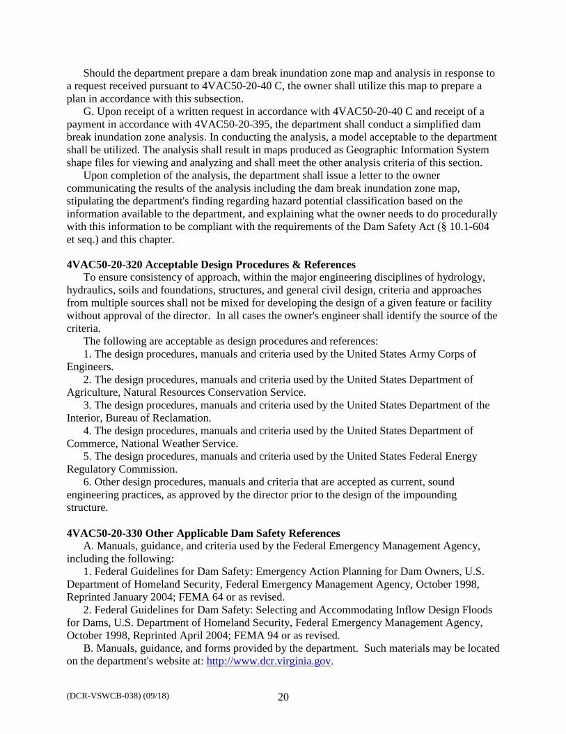
Upon completion of the analysis, the department shall issue a letter to the owner communicating the results of the analysis including the dam break inundation zone map, stipulating the department's finding regarding hazard potential classification based on the information available to the department, and explaining what the owner needs to do procedurally with this information to be compliant with the requirements of the Dam Safety Act (§ 10.1-604 et seq.) and this chapter. 4VAC50-20-320 Acceptable Design Procedures & References
To ensure consistency of approach, within the major engineering disciplines of hydrology, hydraulics, soils and foundations, structures, and general civil design, criteria and approaches from multiple sources shall not be mixed for developing the design of a given feature or facility without approval of the director. In all cases the owner's engineer shall identify the source of the criteria.
The following are acceptable as design procedures and references: 1. The design procedures, manuals and criteria used by the United States Army Corps of
Engineers. 2. The design procedures, manuals and criteria used by the United States Department of
Agriculture, Natural Resources Conservation Service. 3. The design procedures, manuals and criteria used by the United States Department of the
Interior, Bureau of Reclamation. 4. The design procedures, manuals and criteria used by the United States Department of
Commerce, National Weather Service. 5. The design procedures, manuals and criteria used by the United States Federal Energy
Regulatory Commission. 6. Other design procedures, manuals and criteria that are accepted as current, sound
engineering practices, as approved by the director prior to the design of the impounding structure. 4VAC50-20-330 Other Applicable Dam Safety References
A. Manuals, guidance, and criteria used by the Federal Emergency Management Agency, including the following:
1. Federal Guidelines for Dam Safety: Emergency Action Planning for Dam Owners, U.S. Department of Homeland Security, Federal Emergency Management Agency, October 1998, Reprinted January 2004; FEMA 64 or as revised.
2. Federal Guidelines for Dam Safety: Selecting and Accommodating Inflow Design Floods for Dams, U.S. Department of Homeland Security, Federal Emergency Management Agency, October 1998, Reprinted April 2004; FEMA 94 or as revised.
B. Manuals, guidance, and forms provided by the department. Such materials may be located on the department's website at: http://www.dcr.virginia.gov.

(DCR-VSWCB-038) (09/18) 21
Appendix 3 Example Dam Break Analysis Inundation Map (with additional EAP information)