Viper 650/850 Robot with eMB-60R User's · PDF fileViper 650/850 Robot with eMB-60R...
124
I599-E-01 Viper 650/850 Robot with eMB-60R User’s Guide
Transcript of Viper 650/850 Robot with eMB-60R User's · PDF fileViper 650/850 Robot with eMB-60R...
I599-E-01
Viper 650/850 Robotwith eMB-60R
User’s Guide

Viper 650/850 Robot with eMB-60R User’s Guide, 05173-060 Rev GPage 2 of 124
Copyright Notice
The information contained herein is the property of Omron Adept Technologies, Inc., and shallnot be reproduced in whole or in part without prior written approval of Omron Adept Tech-nologies, Inc. The information herein is subject to change without notice and should not be con-strued as a commitment by Omron Adept Technologies, Inc. The documentation is periodicallyreviewed and revised.
Omron Adept Technologies, Inc., assumes no responsibility for any errors or omissions in thedocumentation. Critical evaluation of the documentation by the user is welcomed. Your com-ments assist us in preparation of future documentation. Please submit your comments to: [email protected].
Copyright 2007, 2010 - 2012, 2016 by Omron Adept Technologies, Inc. All rights reserved.
Any trademarks from other companies used in this publication are the property
of those respective companies.
Created in the United States of America

Viper 650/850 Robot with eMB-60R User’s Guide, 05173-060 Rev GPage 3 of 124
Table of Contents
Chapter 1: Introduction 71.1 Product Description 7SmartController EX (Option) 8MotionBlox-60R 8
1.2 How Can I Get Help? 9Corporate Web Site 9Related Manuals 9
Chapter 2: Safety 112.1 Dangers, Warnings, Cautions, and Precautions 112.2 Safety Precautions 122.3 What to Do in an Emergency or Abnormal Situation 122.4 Robot Behavior 13Hardstops 13Limiting Devices 13Singularities 13
2.5 Intended Use of the Robots 132.6 Additional Safety Information 14Manufacturer’s Declaration of Incorporation 14Robot Safety Guide 14Manual Control Pendant 14
Chapter 3: Robot Installation 153.1 Unpacking and Inspecting the Equipment 153.2 Repacking for Relocation 153.3 Environmental and Facility Requirements 163.4 Transporting the Robot 16Precautions when Transporting Robot 16Transport Procedure 18
3.5 Mounting the Robot 203.6 Grounding the Robot 213.7 Mounting the Front Panel 213.8 Description of Connectors on Robot Interface Panel 213.9 Air Lines and Signal Wiring 22Optional Solenoid Cable 24Solenoid Valve Specifications 26
Viper 650/850 Robot with eMB-60R User’s Guide, 05173-060 Rev GPage 4 of 124
Table of Contents
External Mounting Locations on Robot 27
3.10 Designing End-Effectors 27Continuous Turn on J6 27Mass of End-Effector 27Center of Gravity Position of End-Effector 28Moment of Inertia Around J4, J5, and J6 28
Chapter 4: MotionBlox-60R 314.1 Introduction 314.2 Description of Connectors on eMB-60R Interface Panel 324.3 eMB-60R Operation 33Status LED on eMB-60R 33Status Panel 33Brake Release Button on eMB-60R 34Brake Release Connector 35
4.4 Connecting Digital I/O to the System 354.5 Using Digital I/O on eMB-60R XIO Connector 37Optional I/O Products 39XIO Input Signals 39XIO Output Signals 41XIO Breakout Cable 42
4.6 eMB-60R Dimensions 444.7 Mounting the eMB-60R 45
Chapter 5: System Installation 475.1 System Cables, without SmartController EX 47List of Cables and Parts 48Cable Installation Overview 49Optional Cables 50
5.2 System Cables, with SmartController EX 51Installing a SmartController EX Motion Controller 51List of Cables and Parts 52Cable Installation Overview 53Optional Cables 54
5.3 System Cables, with Two Conveyor Encoders 55Pinouts for eAIB XBELT IO Adapter 56
5.4 ACE Software 56User-supplied PC 56Installing ACE Software 56
5.5 Connecting Cables from the eMB-60R to the Robot 575.6 Connecting 24 VDC Power to eMB-60R Servo Controller 58Specifications for 24 VDC Power 58

Viper 650/850 Robot with eMB-60R User’s Guide, 05173-060 Rev GPage 5 of 124
Table of Contents
Details for 24 VDC Mating Connector 59Procedure for Creating 24 VDC Cable 59Installing the 24 VDC Cable 60
5.7 Connecting 200-240 VAC Power to eMB-60R 61Specifications for AC Power 61Facility Overvoltage Protection 62AC Power Diagrams 62Details for AC Mating Connector 63Procedure for Creating 200-240 VAC Cable 63Installing AC Power Cable to eMB-60R 64
5.8 Grounding the Robot System 64Ground Point on Robot Base 65Ground Point on MotionBlox-60R 65Robot-Mounted Equipment Grounding 66
5.9 Installing User-Supplied Safety Equipment 66Emergency Stop Circuits 71Remote Manual Mode 73User Manual/Auto Indication 73User High Power On Indication 73Remote High Power On/Off Control 73High Power On/Off Lamp 74Remote Front Panel or User-Supplied Control Panel Usage 74Remote Pendant Usage 75
Chapter 6: System Operation 776.1 Status Panel Codes 776.2 Brakes 77Installing and Using the Brake Release Box 77Using the Brake Release Switch on UL Robots 78
6.3 Front Panel 796.4 Starting the System for the First Time 80Verifying Installation 81System Start-up Procedure 82Running the ACE Software 82Verifying E-Stop Functions 83Verify Robot Motions 83
6.5 Learning to Program the Robot 846.6 Installing Axis Labels 846.7 Caution Label on Robot 85
Chapter 7: Maintenance 877.1 Field-replaceable Parts 877.2 Periodic Maintenance Schedule 87

Viper 650/850 Robot with eMB-60R User’s Guide, 05173-060 Rev GPage 6 of 124
Table of Contents
7.3 Checking Safety Systems 887.4 Checking Robot Mounting Bolts 887.5 Replacing Encoder Backup Batteries 88Battery Replacement Intervals 88Battery Replacement Procedure 88
7.6 Replacing the eMB-60R Amplifier 92Remove the eMB-60R Amplifier 92Installing a New eMB-60R 92
7.7 Commissioning a System with an eMB-60R 92Safety Commissioning Utilities 93E-Stop Configuration Utility 95E-Stop Verification Utility 95Teach Restrict Configuration Utility 96Teach Restrict Verification Utility 96
7.8 Changing the Lamp in the Front Panel High-Power Indicator 98
Chapter 8: Technical Specifications 1018.1 Robot Dimensions 1018.2 Robot Flange Dimensions 1058.3 Specifications 105Physical 105Performance 106Stopping Distances and Times 107
Chapter 9: IP54/65 Option 1139.1 Introduction 1139.2 Differences from the Standard Robot Model 114Installation Environment 114Robot Connector Panel 114Cable Clearance 115Replacing Encoder Backup Battery 115
Chapter 10: Cleanroom Option 11710.1 Introduction 11710.2 Differences from Standard Robot Model 117Cleanroom Technical Specifications 118Robot Connector Panel 118
10.3 Air Lines and Signal Wiring 11810.4 Cleanroom Cover at J6 Flange 12110.5 Cable Clearance 12110.6 Replacing Encoder Backup Battery 122
Viper 650/850 Robot with eMB-60R User’s Guide, 05173-060 Rev GPage 7 of 124
Chapter 1: Introduction
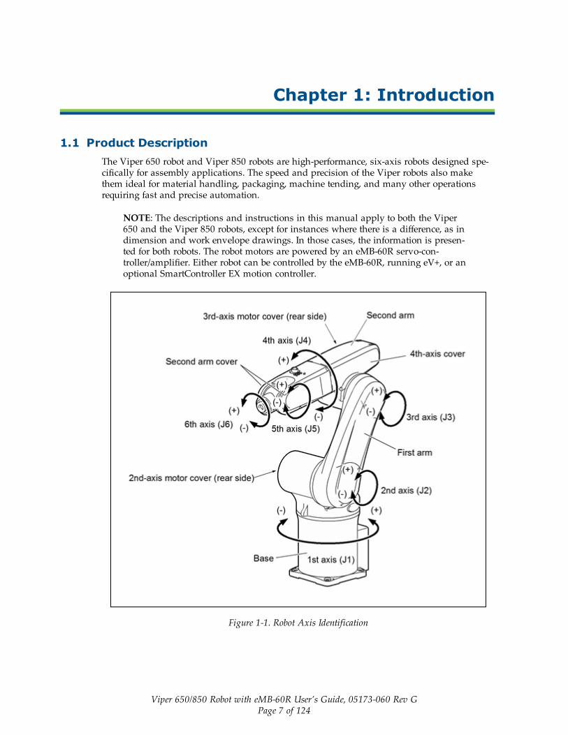
1.1 Product DescriptionThe Viper 650 robot and Viper 850 robots are high-performance, six-axis robots designed spe-cifically for assembly applications. The speed and precision of the Viper robots also makethem ideal for material handling, packaging, machine tending, and many other operationsrequiring fast and precise automation.
NOTE: The descriptions and instructions in this manual apply to both the Viper650 and the Viper 850 robots, except for instances where there is a difference, as indimension and work envelope drawings. In those cases, the information is presen-ted for both robots. The robot motors are powered by an eMB-60R servo-con-troller/amplifier. Either robot can be controlled by the eMB-60R, running eV+, or anoptional SmartController EX motion controller.
Figure 1-1. Robot Axis Identification
Chapter 1: Introduction
Viper 650/850 Robot with eMB-60R User’s Guide, 05173-060 Rev GPage 8 of 124
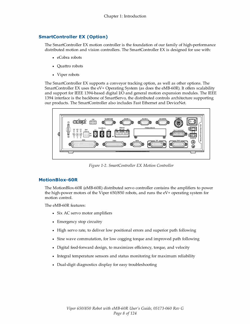
SmartController EX (Option)
The SmartController EX motion controller is the foundation of our family of high-performancedistributed motion and vision controllers. The SmartController EX is designed for use with:
l eCobra robots
l Quattro robots
l Viper robots
The SmartController EX supports a conveyor tracking option, as well as other options. TheSmartController EX uses the eV+ Operating System (as does the eMB-60R). It offers scalabilityand support for IEEE 1394-based digital I/O and general motion expansion modules. The IEEE1394 interface is the backbone of SmartServo, the distributed controls architecture supportingour products. The SmartController also includes Fast Ethernet and DeviceNet.
Figure 1-2. SmartController EX Motion Controller
MotionBlox-60R
The MotionBlox-60R (eMB-60R) distributed servo controller contains the amplifiers to powerthe high-power motors of the Viper 650/850 robots, and runs the eV+ operating system formotion control.
The eMB-60R features:
l Six AC servo motor amplifiers
l Emergency stop circuitry
l High servo rate, to deliver low positional errors and superior path following
l Sine wave commutation, for low cogging torque and improved path following
l Digital feed-forward design, to maximizes efficiency, torque, and velocity
l Integral temperature sensors and status monitoring for maximum reliability
l Dual-digit diagnostics display for easy troubleshooting

Chapter 1: Introduction
Viper 650/850 Robot with eMB-60R User’s Guide, 05173-060 Rev GPage 9 of 124
DC
IN
24V GND
AC
200 -240V
Ø1 XB
ELT
IO
XIO Servo
ENETENETXSYSTEM
Figure 1-3. MotionBlox-60R (eMB-60R)
1.2 How Can I Get Help?
Corporate Web Site
You can access information sources on our corporate web site:
http://www.ia.omron.com
http://www.adept.com
Related Manuals
This manual covers the installation, operation, and maintenance of a Viper 650/850 robot sys-tem. There are additional manuals that cover programming the system, reconfiguring installedcomponents, and adding other optional components. See the following table.

Chapter 1: Introduction
Viper 650/850 Robot with eMB-60R User’s Guide, 05173-060 Rev GPage 10 of 124
Table 1-1. Related Manuals
Manual Title Description
Robot Safety Guide Contains general safety information for all of our robots. A prin-ted copy of this guide ships with each robot.
SmartController User’sGuide
Contains complete information on the installation and operationof the optional SmartController EX and the optional sDIOproduct.
T20 Pendant User'sGuide
Describes the T20 pendant.
IO Blox User’s Guide Describes the IO Blox product.
ACE User’s Guide Describes the installation and use of the ACE software.
Dual RobotConfiguration Procedure
Contains cable diagrams and configuration procedures for a dual-robot system.

Viper 650/850 Robot with eMB-60R User’s Guide, 05173-060 Rev GPage 11 of 124
Chapter 2: Safety
2.1 Dangers, Warnings, Cautions, and PrecautionsThere are six levels of alert notation used in our manuals. In descending order of importance,they are:
DANGER: This indicates an imminently hazardous electrical situationwhich, if not avoided, will result in death or serious injury.
DANGER: This indicates an imminently hazardous situation which, ifnot avoided, will result in death or serious injury.
WARNING: This indicates a potentially hazardous electrical situationwhich, if not avoided, could result in serious injury or major damage tothe equipment.
WARNING: This indicates a potentially hazardous situation which, ifnot avoided, could result in serious injury or major damage to the equip-ment.
CAUTION: This indicates a situation which, if not avoided, could resultin minor injury or damage to the equipment.
Precautions for Safe Use: This indicates precautions on what to do andwhat not to do to ensure using the product safely.
Chapter 2: Safety
Viper 650/850 Robot with eMB-60R User’s Guide, 05173-060 Rev GPage 12 of 124
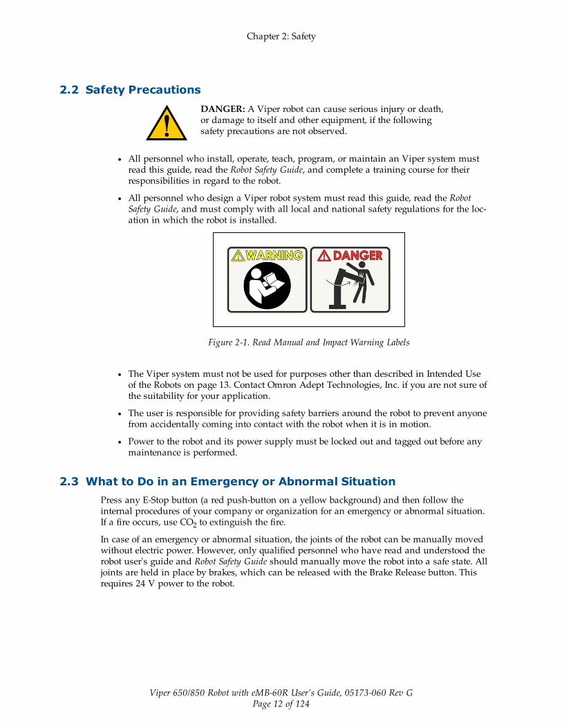
2.2 Safety PrecautionsDANGER: A Viper robot can cause serious injury or death,or damage to itself and other equipment, if the followingsafety precautions are not observed.
l All personnel who install, operate, teach, program, or maintain an Viper system mustread this guide, read the Robot Safety Guide, and complete a training course for theirresponsibilities in regard to the robot.
l All personnel who design a Viper robot system must read this guide, read the RobotSafety Guide, and must comply with all local and national safety regulations for the loc-ation in which the robot is installed.
Figure 2-1. Read Manual and Impact Warning Labels
l The Viper system must not be used for purposes other than described in Intended Useof the Robots on page 13. Contact Omron Adept Technologies, Inc. if you are not sure ofthe suitability for your application.
l The user is responsible for providing safety barriers around the robot to prevent anyonefrom accidentally coming into contact with the robot when it is in motion.
l Power to the robot and its power supply must be locked out and tagged out before anymaintenance is performed.
2.3 What to Do in an Emergency or Abnormal SituationPress any E-Stop button (a red push-button on a yellow background) and then follow theinternal procedures of your company or organization for an emergency or abnormal situation.If a fire occurs, use CO2 to extinguish the fire.
In case of an emergency or abnormal situation, the joints of the robot can be manually movedwithout electric power. However, only qualified personnel who have read and understood therobot user's guide and Robot Safety Guide should manually move the robot into a safe state. Alljoints are held in place by brakes, which can be released with the Brake Release button. Thisrequires 24 V power to the robot.
Chapter 2: Safety
Viper 650/850 Robot with eMB-60R User’s Guide, 05173-060 Rev GPage 13 of 124
2.4 Robot Behavior
Hardstops
If the Viper runs into one of its hardstops, the robot’s motion will stop completely, an envelopeerror will be generated, and power will be cut to the robot motors.
The robot cannot continue to move after hitting a hardstop until the error has been cleared.
The Viper’s hardstops are capable of stopping the robot at any speed, load, and maximum orminimum extension.
Limiting Devices
There are no dynamic or electro-mechanical limiting devices provided by Omron Adept Tech-nologies, Inc. The robot does not have safety-rated soft axis or space limiting.
However, the user can install their own safety rated (category 0 or 1) dynamic limiting devicesif needed, that comply with ISO 10218-1, Clause 5.12.2.
Singularities
There are no singularities with a Viper robot that cause a hazard.
2.5 Intended Use of the RobotsDANGER: Viper robots are not collaborative robots. Theyrequire a dedicated work area that will prevent personnelfrom coming into contact with them during operation.
The normal and intended use of these robots does not create hazards.
The Viper robots have been designed and constructed in accordance with the relevant require-ments of IEC 60204-1.
The Viper robots are intended for use in parts assembly and material handling for payloadsless than 5 kg (11 lb). See Specifications on page 105 for complete information on the robot spe-cifications. Refer to the Robot Safety Guide for details on the intended use of Viper robots.
Viper robots are for not intended for:
l Use in the presence of ionizing or non-ionizing radiation
l Use in potentially explosive atmospheres
l Use in medical or life saving applications
l Use in a residential setting. They are for industrial use only.
l Use before performing a risk assessment

Chapter 2: Safety
Viper 650/850 Robot with eMB-60R User’s Guide, 05173-060 Rev GPage 14 of 124
2.6 Additional Safety InformationWe provide other sources for more safety information:
Manufacturer’s Declaration of Incorporation
This lists all standards with which the robot complies. The Manufacturer’s Declarations forthe Viper robot and other products are in theManufacturer's Declarations Guide.
Robot Safety Guide
The Robot Safety Guide provides detailed information on safety for robots. It ships with eachrobot.
Manual Control Pendant
The E-Stop provided in the T20 Pendant complies with ISO 10218-1 (per clause 5.5.2), withstop category 1 (per IEC 60204). The E-stop button complies with ISO 13850. The E-Stop meetsthe requirements of PL-d per ISO 13849.
NOTE: Omron Adept Technologies, Inc. does not offer a cableless(wireless) pendant.
The manual control pendant can only move one robot at a time, even if multiple robots areconnected to a SmartController, and the pendant is connected to the SmartController.

Viper 650/850 Robot with eMB-60R User’s Guide, 05173-060 Rev GPage 15 of 124
Chapter 3: Robot Installation
3.1 Unpacking and Inspecting the EquipmentCarefully inspect all shipping crates for evidence of damage during transit. If any damage isapparent, request that the carrier’s agent be present at the time the container is unpacked.
Before signing the carrier’s delivery sheet, please compare the actual items received (not justthe packing slip) with your equipment purchase order and verify that all items are present andthat the shipment is correct and free of visible damage.
If the items received do not match the packing slip, or are damaged, do not sign the receipt.Contact Omron Adept Technologies, Inc. as soon as possible.
If the items received do not match your order, please contact Omron Adept Technologies, Inc.immediately.
Inspect each item for external damage as it is removed from its container. If any damage isevident, contact Omron Adept Technologies, Inc..
Retain all containers and packaging materials. These items may be necessary to settle claimsor, at a later date, to relocate equipment.
3.2 Repacking for RelocationIf the robot or other equipment needs to be relocated, reverse the steps in the installation pro-cedures that follow in this chapter. Reuse all original packing containers and materials and fol-low all safety notes used for installation. Improper packaging for shipment will void yourwarranty. Specify this to the carrier if the robot is to be shipped.
CAUTION: Before transportation, set the robot in a transportposition by manually moving the second, third, and fourth axes.See the following figure.
Figure 3-1. Robot in Transport Position

Chapter 3: Robot Installation
Viper 650/850 Robot with eMB-60R User’s Guide, 05173-060 Rev GPage 16 of 124
3.3 Environmental and Facility RequirementsThe robot system installation must meet the operating environment requirements shown in thefollowing table.
Table 3-1. Robot System Operating Environment Requirements
Item Condition
Flatness of themounting surface
0.1 mm/500 mm
Installation type Floor-mount or Overhead-mount
Ambienttemperature
During operation: 0 to 40° CDuring storage and transportation: -25 to 60° C
Humidity During operation: 90% or less (Non-condensing)During storage and transportation: 75% or less (Non-condensing)
Altitude up to 2000 m (6500 ft)
Vibration During operation: 4.9 m/s2 (0.5 G) or lessDuring storage and transportation: 29.4 m/s2 (3 G) or less
Safe InstallationEnvironment
The robot should not be installed in an environment where:l There are flammable gases or liquidsl There are any acidic, alkaline, or other corrosive gasesl There is sulfuric or other types of cutting or grinding oil mistl There are any large-sized inverters, high output/high frequencytransmitters, large contactors, welders, or other sources of elec-trical noise
l There are any shavings from metal processing or other conductivematerial flying about
l It may be directly exposed to water, oil, or cutting chips
Working space,etc.
l Sufficient service space must be available for inspection and dis-assembly.
l Keepwiring space (230 mm or more) behind the robot, and fastenthe wiring to the mounting face or beam so that the weight of thecables will not be directly applied to the connectors.
Protective EarthGround
Grounding resistance: 10 Ohms or lessSee Robot Installation on page 15.
3.4 Transporting the Robot
Precautions when Transporting Robot
l The robot weighs almost 30 kg (66 lb). Use a crane suitable for the robot weight.
l Have at least two workers handle this job.
l Workers should wear hardhats, safety shoes, and gloves during transport.

Chapter 3: Robot Installation
Viper 650/850 Robot with eMB-60R User’s Guide, 05173-060 Rev GPage 17 of 124
l Do not hold the first arm, elbow, either side of the 2nd arm, 2nd-axis cover, or 3rd-axiscover, or apply force to any of them. See Robot Axis Identification on page 7.
WARNING: Do not attempt to lift the robot at any pointsother than the eyebolts provided. Do not attempt to moveany robot links until the robot has been secured in position.Failure to comply could result in the robot falling and caus-ing either personnel injury or equipment damage.
Figure 3-2. Robot in Hoisting Sling

Chapter 3: Robot Installation
Viper 650/850 Robot with eMB-60R User’s Guide, 05173-060 Rev GPage 18 of 124
Transport Procedure
Step Procedure Drawing
1 Before transportation, set the robotin a transport position as shown atright by manually moving thesecond, third, and fourth axes.When initially unpacked, the robot isin the transport position, so this stepis not required.
Transport Position
Axis Angle
First axis (J1) 0°
Second axis (J2) -145°
Third axis (J3) +243°
Fourth axis (J4) -90°
Fifth axis (J5) -90°
2 Disconnect the robot control cable,air hoses, and user signal cables fromthe robot.When the robot is first unpacked,this step is not required.
3 As shown at right, mount the eye-bolts.When delivered, the robot is packedwith eyebolts attached, so this step isnot required
4 As shown at right, place a wastecloth on the second axis and pass thewire through the two eyebolts.
Note: Before transporting the robot,check that the path to the mounting

Chapter 3: Robot Installation
Viper 650/850 Robot with eMB-60R User’s Guide, 05173-060 Rev GPage 19 of 124
Step Procedure Drawing
location is free of obstacles.
5 Worker A: Remove the four boltswhile supporting the robot to preventit from tipping over.
6 Worker B: Operate the crane andmove the robot to the mounting loc-ation.
7 Worker B: Put the robot down in themounting location.Worker A: Temporarily secure therobot base with four bolts.
8 Secure the robot according to theinstructions in Mounting the Roboton page 20.
9 Remove the eyebolts from the robot. WARNING: Before running the robot, be sureto remove the eyebolts. Otherwise, the robotarm will strike these eyebolts.
Chapter 3: Robot Installation
Viper 650/850 Robot with eMB-60R User’s Guide, 05173-060 Rev GPage 20 of 124
3.5 Mounting the Robot
2X Ø6
200
160
R20
66 ±0.05 142.3
4X Ø12 THRU
For M10
18
4 ±
0.0
5
16
0
20
0
+0.012
- 0
Diamond-shaped pin
Units are mm
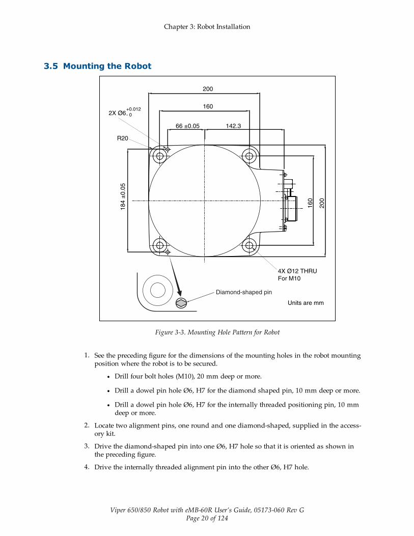
Figure 3-3. Mounting Hole Pattern for Robot
1. See the preceding figure for the dimensions of the mounting holes in the robot mountingposition where the robot is to be secured.
l Drill four bolt holes (M10), 20 mm deep or more.
l Drill a dowel pin hole Ø6, H7 for the diamond shaped pin, 10 mm deep or more.
l Drill a dowel pin hole Ø6, H7 for the internally threaded positioning pin, 10 mmdeep or more.
2. Locate two alignment pins, one round and one diamond-shaped, supplied in the access-ory kit.
3. Drive the diamond-shaped pin into one Ø6, H7 hole so that it is oriented as shown inthe preceding figure.
4. Drive the internally threaded alignment pin into the other Ø6, H7 hole.

Chapter 3: Robot Installation
Viper 650/850 Robot with eMB-60R User’s Guide, 05173-060 Rev GPage 21 of 124
NOTE: Be sure to use the alignment pins. It can minimize positional devi-ations that may be caused by the removal/installation of the robot for main-tenance and reduce vibration during operation.
5. Set the robot into place on the robot mount. When transporting the robot, follow theinstructions given in Transporting the Robot on page 16.
6. Secure the robot to the mount with four bolts and plain washers.
l Bolt: M10 x 30 mm (strength class: 12.9)
l Tightening torque: 70 ± 14 N·m (52 ± 10 ft-lbf)
3.6 Grounding the RobotGround the grounding terminal of the robot with a wire of 12 AWG or larger. Ground res-istance must be less than 10 Ohms. See Grounding the Robot System on page 64.
3.7 Mounting the Front PanelThe Front Panel must be installed outside of the workspace.
NOTE: European standards require that the remote High Power push-button be loc-ated outside of the workspace of the robot.
3.8 Description of Connectors on Robot Interface Panel
CN22
CN20
AIR1
AIR2
Grounding terminal (M5)
CN22 Power/Signal Cable - to eMB-60R
CN20
AIR 1
AIR 2
Figure 3-4. Robot Interface Panel

Chapter 3: Robot Installation
Viper 650/850 Robot with eMB-60R User’s Guide, 05173-060 Rev GPage 22 of 124
Table 3-2. Robot Interface Connections
CN22 The Arm Power/Signal cable from the eMB-60R is installed at this connector.
CN20 Pins 1 to 10 are wired directly to corresponding pins 1 to 10 on CN21 on the upperarm. Pins 12 to 18 are for solenoid control. See Air Lines and Signal Wiring onpage 22.
AIR 1 Air line connector (BSPT1/4) for three solenoids in robot. Air Lines and Signal Wir-ing on page 22.
AIR 2 Air line connector (BSPT1/4), connects directly to AIR 2 on the second (upper)arm.
GroundingTerminal
Protective earth ground point on the robot. See Grounding the Robot on page 21.
3.9 Air Lines and Signal WiringThe robot is equipped with seven air lines. Six lines, from AIR1 input, are controlled by thethree internal solenoid valves. One line, from AIR2 input, is connected directly to AIR2 on thesecond arm. There are ten user electric lines. See the following figures and tables.

Chapter 3: Robot Installation
Viper 650/850 Robot with eMB-60R User’s Guide, 05173-060 Rev GPage 23 of 124
Air intake/Exhaust States.
Air tubing joint Valve Signal
AIR1 Airintake
Exhaust Solenoidvalve
Solenoid
A B
1A 1B 1 ON OFF
1B 1A 1 OFF ON
2A 2B 2 ON OFF
2B 2A 2 OFF ON
3A 3B 3 ON OFF
3B 3A 3 OFF ON
AIR2
CN20 Pin AssignmentsNPN type (source IN, sink OUT)
CN20 pin No. Used for:
12 +24 V
13 Solenoid 1A (solenoid valve 1)
14 Solenoid 1B (solenoid valve 1)
15 Solenoid 2A (solenoid valve 2)
16 Solenoid 2B (solenoid valve 2)
17 Solenoid 3A (solenoid valve 3)
18 Solenoid 3B (solenoid valve 3)
PNP type (sink IN, source OUT)
CN20 pin No. Used for:
12 0 V
13 Solenoid 1A (solenoid valve 1)
14 Solenoid 1B (solenoid valve 1)
15 Solenoid 2A (solenoid valve 2)
16 Solenoid 2B (solenoid valve 2)
17 Solenoid 3A (solenoid valve 3)
18 Solenoid 3B (solenoid valve 3)
CN21 pin layout
CN20 pin layout
View A
Air line joint (M5)
Grounding Terminal (M5)
AIR1 Air line joint (BSPT1/4)
AIR2 Air line joint (BSPT1/4)
Connector (CN21)
for end-effector control
signal wires
A
B
View B
Connector (CN20)
for end-effector signal/valve
control wires
Note 1: Pins #1 to #10 on CN21 and those onCN20 are connected with each other. Theallowable current per line is 1 A.
Note 2: Use the supplied mating connectorsets for CN20 and CN21. See CleanroomOption on page 117 for information about themating connectors on Cleanroom and IP54/65robots.
Chapter 3: Robot Installation
Viper 650/850 Robot with eMB-60R User’s Guide, 05173-060 Rev GPage 24 of 124
Connector set partNo.
Connector No. Model and part name Appearance
05019-000 for CN20 SRCN6A25-24S (round type con-nector) Japan Aviation Elec-tronics Industry Ltd.
for CN21 JMLP1610M (L type plug con-nector) DDK Electronics, Inc.
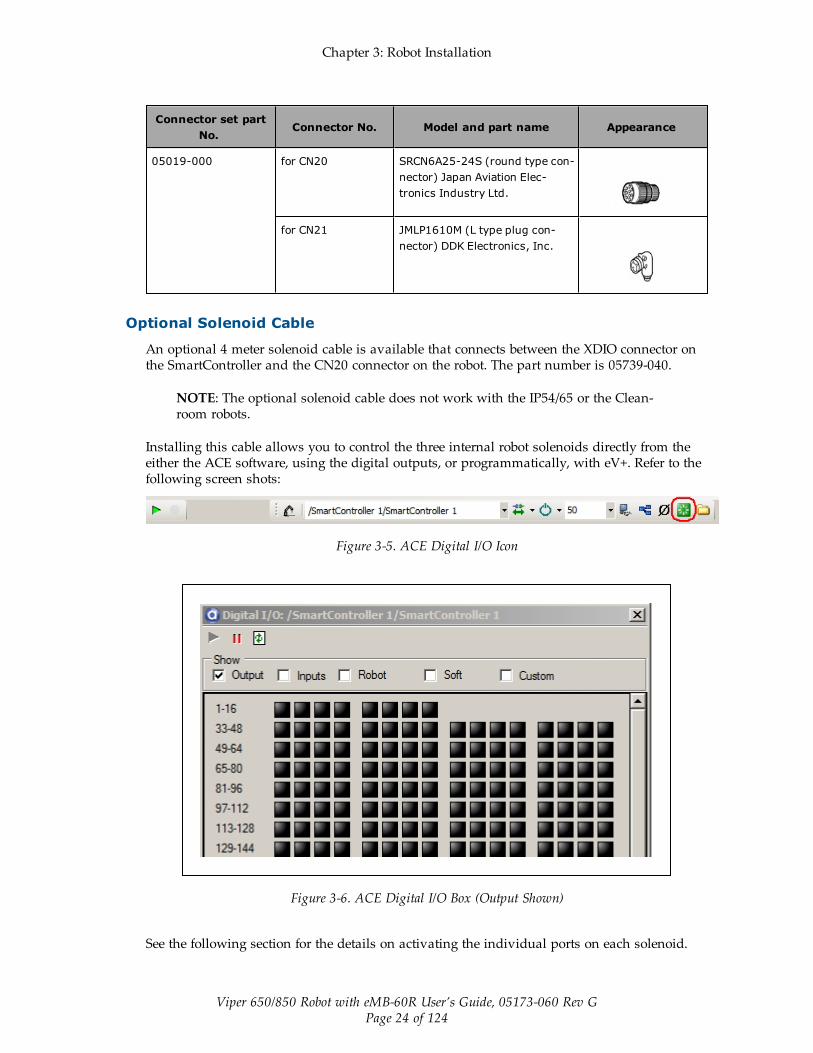
Optional Solenoid Cable
An optional 4 meter solenoid cable is available that connects between the XDIO connector onthe SmartController and the CN20 connector on the robot. The part number is 05739-040.
NOTE: The optional solenoid cable does not work with the IP54/65 or the Clean-room robots.
Installing this cable allows you to control the three internal robot solenoids directly from theeither the ACE software, using the digital outputs, or programmatically, with eV+. Refer to thefollowing screen shots:
Figure 3-5. ACE Digital I/O Icon
Figure 3-6. ACE Digital I/O Box (Output Shown)
See the following section for the details on activating the individual ports on each solenoid.

Chapter 3: Robot Installation
Viper 650/850 Robot with eMB-60R User’s Guide, 05173-060 Rev GPage 25 of 124
Table 3-3. Viper Solenoid Control
Active Output Port Signal States1
Solenoid 1 A 0001 –0002
B –0001 0002
Solenoid 2 A 0003 –0004
B –0003 0004
Solenoid 3 A 0005 –0006
B –0005 0006
1 The two-position, double solenoids require both signal states to beactivated. Invalid states will result in indeterminate outputs.
In addition to controlling the internal robot solenoids, the Solenoid cable brings a portion ofthe other XDIO signals out to the CN21 connector at the top of the robot. See the followingtable for details of which signals are available at CN21. See the SmartController User's Guide forthe electrical specifications for the signals from the XDIO connector.
Table 3-4. CN21 Signal List When Using Solenoid Cable
CN21 Pin #Signal from XDIO onSmartController CN21 Pin #
Signal from XDIO onSmartController
1 Input 1001a 6 Not connected
2 Input 1002a 7 Output 0007b
3 Input 1003a 8 Output 0008b
4 Input 1004a 9 24 V Outputc
5 Input 1005a 10 Ground
aInputs 1001 to 1005 are preconfigured as low-active (sinking) inputs.
bOutputs 0007 and 0008 are preconfigured as high-side (sourcing) outputs.
cLimited to a combined total of 1A of current.
Chapter 3: Robot Installation
Viper 650/850 Robot with eMB-60R User’s Guide, 05173-060 Rev GPage 26 of 124
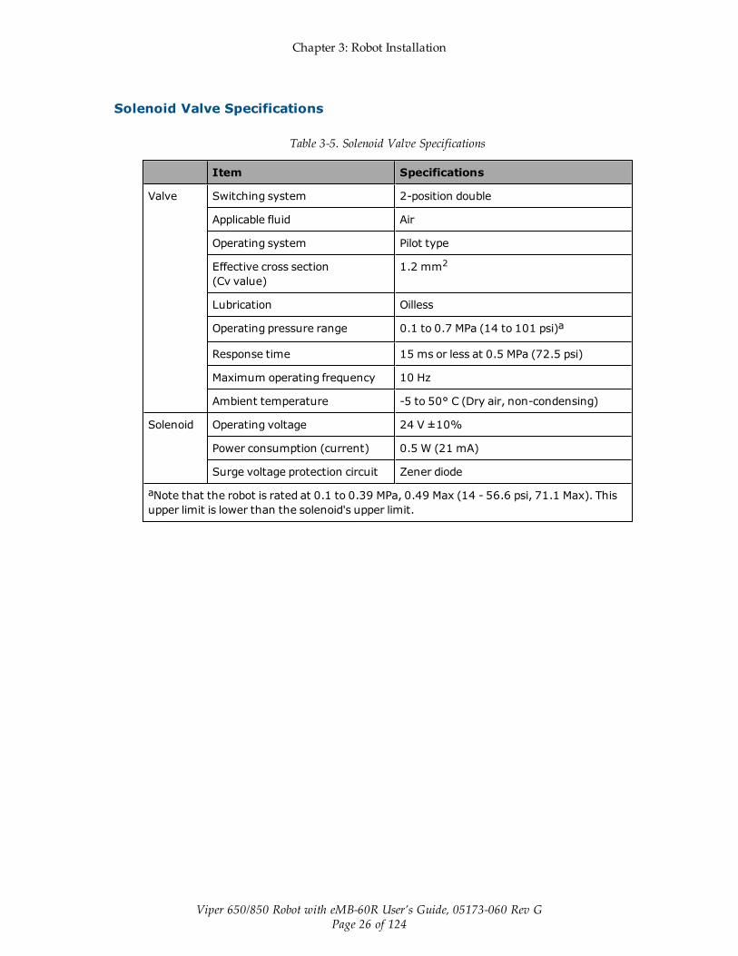
Solenoid Valve Specifications
Table 3-5. Solenoid Valve Specifications
Item Specifications
Valve Switching system 2-position double
Applicable fluid Air
Operating system Pilot type
Effective cross section(Cv value)
1.2 mm2
Lubrication Oilless
Operating pressure range 0.1 to 0.7 MPa (14 to 101 psi)a
Response time 15 ms or less at 0.5 MPa (72.5 psi)
Maximum operating frequency 10 Hz
Ambient temperature -5 to 50° C (Dry air, non-condensing)
Solenoid Operating voltage 24 V ±10%
Power consumption (current) 0.5 W (21 mA)
Surge voltage protection circuit Zener diode
aNote that the robot is rated at 0.1 to 0.39 MPa, 0.49 Max (14 - 56.6 psi, 71.1 Max). Thisupper limit is lower than the solenoid's upper limit.
Chapter 3: Robot Installation
Viper 650/850 Robot with eMB-60R User’s Guide, 05173-060 Rev GPage 27 of 124
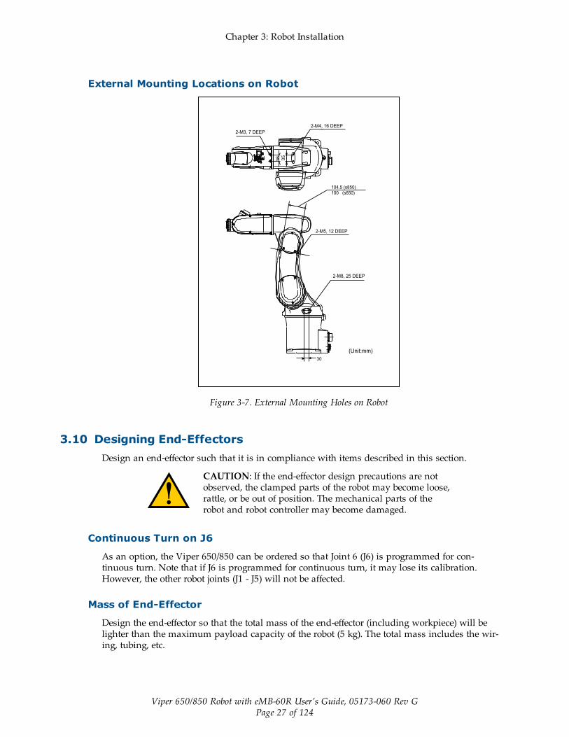
External Mounting Locations on Robot
Figure 3-7. External Mounting Holes on Robot
3.10 Designing End-EffectorsDesign an end-effector such that it is in compliance with items described in this section.
CAUTION: If the end-effector design precautions are notobserved, the clamped parts of the robot may become loose,rattle, or be out of position. The mechanical parts of therobot and robot controller may become damaged.
Continuous Turn on J6
As an option, the Viper 650/850 can be ordered so that Joint 6 (J6) is programmed for con-tinuous turn. Note that if J6 is programmed for continuous turn, it may lose its calibration.However, the other robot joints (J1 - J5) will not be affected.
Mass of End-Effector
Design the end-effector so that the total mass of the end-effector (including workpiece) will belighter than the maximum payload capacity of the robot (5 kg). The total mass includes the wir-ing, tubing, etc.

Chapter 3: Robot Installation
Viper 650/850 Robot with eMB-60R User’s Guide, 05173-060 Rev GPage 28 of 124
Center of Gravity Position of End-Effector
Design an end-effector so that the center of gravity of the end-effector (including workpiece) iswithin the range shown in the following figure.
Figure 3-8. Allowable Range of Center of Gravity of End-effector
Moment of Inertia Around J4, J5, and J6
Design an end-effector so that its moments of inertia around J4, J5, and J6 (including mass ofworkpiece) do not exceed the maximum allowable moments of inertia of the robot.
l Maximum allowable moment of inertia around J4 and J5: 0.295 kgm2
l Maximum allowable moment of inertia around J6: 0.045 kgm2
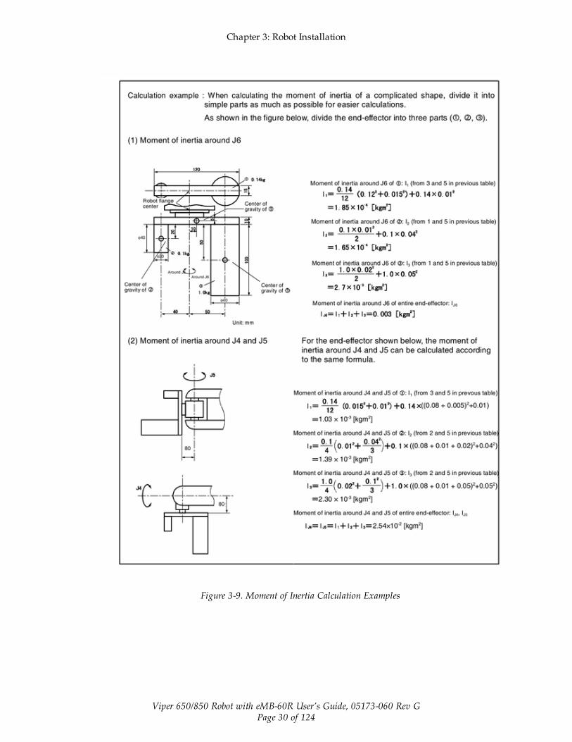
When calculating the moment of inertia around J4, J5, and J6 of the end-effector, use the for-mulas given in the following table. See Moment of Inertia Calculation Examples on page 30.

Chapter 3: Robot Installation
Viper 650/850 Robot with eMB-60R User’s Guide, 05173-060 Rev GPage 29 of 124
Table 3-6. Moment of Inertia Formulas
Chapter 3: Robot Installation
Viper 650/850 Robot with eMB-60R User’s Guide, 05173-060 Rev GPage 30 of 124
Figure 3-9. Moment of Inertia Calculation Examples
Viper 650/850 Robot with eMB-60R User’s Guide, 05173-060 Rev GPage 31 of 124
Chapter 4: MotionBlox-60R
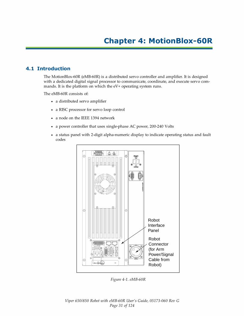
4.1 IntroductionThe MotionBlox-60R (eMB-60R) is a distributed servo controller and amplifier. It is designedwith a dedicated digital signal processor to communicate, coordinate, and execute servo com-mands. It is the platform on which the eV+ operating system runs.
The eMB-60R consists of:
l a distributed servo amplifier
l a RISC processor for servo loop control
l a node on the IEEE 1394 network
l a power controller that uses single-phase AC power, 200-240 Volts
l a status panel with 2-digit alpha-numeric display to indicate operating status and faultcodes
DC
IN
24V GND
AC
200 -240V
Ø1 XB
ELT
IO
XIO Servo
ENETENETXSYSTEM
Robot
Interface
Panel
Robot
Connector
(for Arm
Power/Signal
Cable from
Robot)
Figure 4-1. eMB-60R

Chapter 4: MotionBlox-60R
Viper 650/850 Robot with eMB-60R User’s Guide, 05173-060 Rev GPage 32 of 124
4.2 Description of Connectors on eMB-60R Interface Panel
Figure 4-2. eMB-60R Interface Panel
Table 4-1. Connectors on the eMB-60R Interface Panels
24 VDC For connecting user-supplied 24 VDC power. The mating connector is provided.
Ground Point For connecting cable shield from user-supplied 24 VDC cable.
200/240VAC
For connecting 200-240 VAC, single-phase, input power. The mating con-nector is provided.
SmartServo For connecting the IEEE 1394 cable from the controllerSmartServo to a SmartServo on the eMB-60R.
XIO For user I/O signals for peripheral devices. This connector provides 8 outputsand 12 inputs. See Connecting Digital I/O to the System on page 35 for con-nector pin allocations for inputs and outputs. That section also contains detailson how to access these I/O signals. (DB-26, high density, female)
XSYSTEM Includes the functions of the XPANEL and XSLV on the legacy MB-60R. Con-nects to the controller XSYS connector.This requires either an eAIB XSLV Adapter cable to connect to the XSYS cable,or an eAIB XSYS cable (HDB44-to-DB9,male), which replaces the XSYS cable.
ENET Reserved for future use.
XBELTIO Adds two belt encoders, EXPIO, and an RS-232 interface (which is reserved forfuture use).
Chapter 4: MotionBlox-60R
Viper 650/850 Robot with eMB-60R User’s Guide, 05173-060 Rev GPage 33 of 124
4.3 eMB-60R Operation
Status LED on eMB-60R
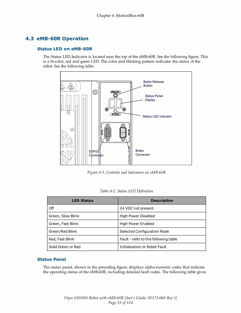
The Status LED Indicator is located near the top of the eMB-60R. See the following figure. Thisis a bi-color, red and green LED. The color and blinking pattern indicates the status of therobot. See the following table.
Figure 4-3. Controls and Indicators on eMB-60R
Table 4-2. Status LED Definition
LED Status Description
Off 24 VDC not present
Green, Slow Blink High Power Disabled
Green, Fast Blink High Power Enabled
Green/Red Blink Selected Configuration Node
Red, Fast Blink Fault - refer to the following table
Solid Green or Red Initialization or Robot Fault
Status Panel
The status panel, shown in the preceding figure, displays alpha-numeric codes that indicatethe operating status of the eMB-60R, including detailed fault codes. The following table gives

Chapter 4: MotionBlox-60R
Viper 650/850 Robot with eMB-60R User’s Guide, 05173-060 Rev GPage 34 of 124
definitions of the fault codes. These codes provide details for quickly isolating problems duringtroubleshooting.
Table 4-3. Status Panel Codes
LED Status Code LED Status Code
OK No Fault H# High Temp Encoder (Joint #)
ON High Power ON Status hV High Voltage Bus Fault
MA Manual Mode I# Initialization Stage (Step#)
24 24 V Supply Fault M# Motor Stalled (Joint #)
A# Amp Fault (Joint #) NV Non-Volatile Memory
B# IO Blox Fault (Address #) P# Power System Fault (Code #)
BA Backup Battery Low Voltage PR Processor Overloaded
AC AC Power Fault RC RSC Fault
D# Duty Cycle Exceeded (Joint #) S# Safety System Fault (Code #)
E# Encoder Fault (Joint #) SE E-Stop Delay Fault
ES E-Stop SW Watchdog Timeout
F# External Sensor Stop T# Safety System Fault (Code 10 + #)
FM Firmware Mismatch TR Teach Restrict Fault
FW IEEE 1394 Fault V# Hard Envelope Error (Joint #)
h# h# High Temp Amp (Joint #)
For more information on status codes, refer to the Status Codes for Embedded Products document.
NOTE: Due to the nature of the Viper 650/850 robot’s bus line encoder wiring, asingle encoder wiring error may result in multiple channels of displayed encodererrors. Reference the lowest encoder number displayed.
Brake Release Button on eMB-60R
A Brake Release button is located at the top right of the eMB-60R. See Controls and Indicatorson eMB-60R on page 33. When pressed, the button will disable High Power and display “BK”on the eMB-60R, but no brakes will be released. Because of the nature of a Viper robot, youhave to specify one joint to release with a brake release, so this button is only used with theCobra 350 robot.
NOTE: If this button is pressed while high power is on, high power will auto-matically shut down.
For manual release of the brakes on the Viper 650/850 robot, a Brake Release connector isprovided on the eMB-60R for connecting a manual brake release box. See the following section

Chapter 4: MotionBlox-60R
Viper 650/850 Robot with eMB-60R User’s Guide, 05173-060 Rev GPage 35 of 124
for more details. Also, an integrated brake release switch is provided on UL robots. See Brakeson page 77.
Brake Release Connector
The 9-pin Brake Release connector provides an interface for connecting a manual brake releasebox.
Table 4-4. Brake Release Connector Pinouts
Pin # Description Pin Location
1 Release1_N
DB-9 FemaleBrake Connector
2 Release2_N
3 Release3_N
4 Release4_N
5 Release5_N
6 Release6_N
7 GND
8 Not connected
9 24 V
Mating Connector:D-Subminiature 9-Pin Male
4.4 Connecting Digital I/O to the SystemYou can connect digital I/O to the system in several different ways. See the following table andfigure.
Table 4-5. Digital I/O Connection Options
Product I/O Capacity For more details
XIO Connector oneMB-60R
12 inputs8 outputs
see Using Digital I/O on eMB-60R XIO Connector on page37
XDIO Connector on optionalSmartController
12 inputs8 outputs
see SmartController User’sGuide
Optional IO Blox Devices, con-nect to EXPIO connector onthe eMB-60R
8 inputs, 8 outputs per device;up to four IO Blox devices persystem
see IO Blox User’s Guide
Optional sDIOModule, con-nects to controller
32 inputs, 32 outputs per mod-ule; up to four sDIO devices persystem
see SmartController User’sGuide

Chapter 4: MotionBlox-60R
Viper 650/850 Robot with eMB-60R User’s Guide, 05173-060 Rev GPage 36 of 124
SF
IEEE-1394
X2
SC
-DIOLINK
*S/N 3563-XXXXX*
X1
24V 0.5A
OK
X4
- + - +
1.1 1.2XDC1 XDC2
X3Optional
sDIO #1
SmartController EX
eMB-60R
Optional
IO Blox Device
XIO Connector
12 Input signals: 1097 to 1108
8 Output signals: 0097 to 0104
XDIO Connector
12 Input signals: 1001 to 1012
8 Output signals: 0001 to 0008
IO Blox #1
8 Input signals: 1113 to 1120
8 Output signals: 0105 to 0112
sDIO #1
32 Input signals: 1033 to 1064
32 Output signals: 0033 to 0064
DC
IN
24VGND
AC
200 -
240V
Ø1
XB
ELT
IO
XIO Servo
ENETENETXSYSTEM
Figure 4-4. Connecting Digital I/O to the System
Table 4-6. Digital I/O Signal Ranges
Type Signal Range
SmartController XDIO connector Inputs 1001 - 1012
Outputs 0001 - 0008
sDIOModule 1 Inputs 1033 - 1064
Outputs 0033 - 0064
sDIOModule 2 Inputs 1065 - 1096
Outputs 0065 - 0096

Chapter 4: MotionBlox-60R
Viper 650/850 Robot with eMB-60R User’s Guide, 05173-060 Rev GPage 37 of 124
Type Signal Range
eMB-60R XIO connector Inputs 1097 - 1108
Outputs 0097 - 0104
IO Blox 1 Inputs 1113 - 1120
Outputs 0105 - 0112
IO Blox 2 Inputs 1121 - 1128
Outputs 0113 - 0120
IO Blox 3 Inputs 1129 - 1136
Outputs 0121 - 0128
IO Blox 4 Inputs 1137 - 1144
Outputs 0129 - 0136
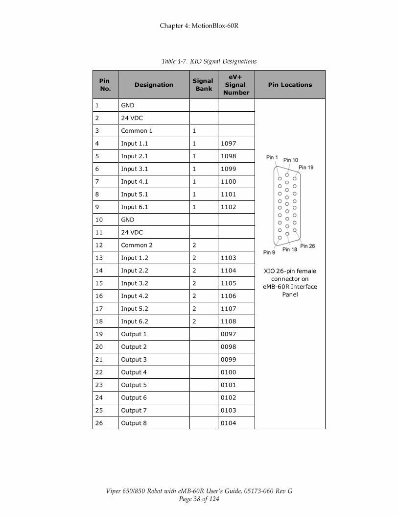
4.5 Using Digital I/O on eMB-60R XIO ConnectorThe XIO connector on the eMB-60R interface panel offers access to digital I/O, 12 inputs and 8outputs. These signals can be used by eV+ to perform various functions in the workcell. Seethe following table for the XIO signal designations.
l 12 Inputs, signals 1097 to 1108
l 8 Outputs, signals 0097 to 0104
Chapter 4: MotionBlox-60R
Viper 650/850 Robot with eMB-60R User’s Guide, 05173-060 Rev GPage 38 of 124
Table 4-7. XIO Signal Designations
PinNo. Designation Signal
Bank
eV+SignalNumber
Pin Locations
1 GND
XIO 26-pin femaleconnector on
eMB-60R InterfacePanel
2 24 VDC
3 Common 1 1
4 Input 1.1 1 1097
5 Input 2.1 1 1098
6 Input 3.1 1 1099
7 Input 4.1 1 1100
8 Input 5.1 1 1101
9 Input 6.1 1 1102
10 GND
11 24 VDC
12 Common 2 2
13 Input 1.2 2 1103
14 Input 2.2 2 1104
15 Input 3.2 2 1105
16 Input 4.2 2 1106
17 Input 5.2 2 1107
18 Input 6.2 2 1108
19 Output 1 0097
20 Output 2 0098
21 Output 3 0099
22 Output 4 0100
23 Output 5 0101
24 Output 6 0102
25 Output 7 0103
26 Output 8 0104

Chapter 4: MotionBlox-60R
Viper 650/850 Robot with eMB-60R User’s Guide, 05173-060 Rev GPage 39 of 124
Optional I/O Products
These optional products are also available for use with digital I/O:
l XIO Breakout Cable, 5 meters long, with flying leads on user’s end. See XIO BreakoutCable on page 42 for information. This cable is not compatible with the XIO Ter-mination Block mentioned below.
l XIO Termination Block, with terminals for user wiring, plus input and output statusLEDs. Connects to the XIO connector with 6-foot cable. See the XIO Termination BlockInstallation Guide for details.
XIO Input Signals
The 12 input channels are arranged in two banks of six. Each bank is electrically isolated fromthe other bank and is optically isolated from the eMB-60R ground. The six inputs within eachbank share a common source/sink line.
The inputs are accessed through direct connection to the XIO connector (see the followingtable), or through the optional XIO Termination Block. See the documentation supplied withthe Termination Block for details.
The XIO inputs cannot be used for REACTI programming, high-speed interrupts, or vision trig-gers. Refer to the eV+ user guides on the corporate website.
XIO Input Specifications
Table 4-8. XIO Input Specifications
Parameter Value
Operational voltage range 0 to 30 VDC
OFF state voltage range 0 to 3 VDC
ON state voltage range 10 to 30 VDC
Typical threshold voltage Vin= 8 VDC
Operational current range 0 to 7.5 mA
OFF state current range 0 to 0.5 mA
ON state current range 2.5 to 6 mA
Typical threshold current 2.0 mA
Impedance (Vin/Iin) 3.9 KΩminimum
Current at Vin= +24 VDC Iin ≤ 6 mA
Turn on response time (hardware)Software scan rate/response time
5 µsec maximum16 ms scan cycle/32 msmax response time
Turn off response time (hardware)Software scan rate/response time
5 µsec maximum16 ms scan cycle/32 msmax response time

Chapter 4: MotionBlox-60R
Viper 650/850 Robot with eMB-60R User’s Guide, 05173-060 Rev GPage 40 of 124
NOTE: The input current specifications are provided for reference. Voltage sourcesare typically used to drive the inputs.
Typical Input Wiring Example
Figure 4-5. Typical User Wiring for XIO Input Signals
NOTE: The off-state current range exceeds the leakage current of XIO outputs. Thisguarantees that the inputs will not be turned on by the leakage current from the out-puts. This is useful in situations where the outputs are looped-back to the inputs formonitoring purposes.

Chapter 4: MotionBlox-60R
Viper 650/850 Robot with eMB-60R User’s Guide, 05173-060 Rev GPage 41 of 124
XIO Output Signals
The eight digital outputs share a common, high-side (sourcing) Driver IC. The driver isdesigned to supply any kind of load with one side connected to ground. It is designed for arange of user-provided voltages from 10 to 24 VDC and each channel is capable of up to 0.7 Aof current. This driver has overtemperature protection, current limiting, and shorted load pro-tection. In the event of an output short or other overcurrent situation, the affected output of theDriver IC turns off and back on automatically to reduce the temperature of the IC. The Driverdraws power from the primary 24 VDC input to the robot through a self-resetting polyfuse.
The outputs are accessed through direct connection to the XIO connector (see See "XIO SignalDesignations"), or through the optional XIO Termination Block. See the documentation sup-plied with the Termination Block for details.
XIO Output Specifications
Table 4-9. XIO Output Circuit Specifications
Parameter Value
Power supply voltage range See System Operation
Operational current range,per channel
Iout ≤ 700 mA
Total Current Limitation, all channelson.
Itotal ≤ 1.0 A@ 50° C ambientItotal ≤ 1.5 A@ 25° C ambient
On-state resistance (Iout= 0.5 A) Ron ≤ 0.32 Ω@ 85° C
Output leakage current Iout ≤ 25 µA
Turn-on response time 125 µsec max., 80 µsec typical(hardware only)
Turn-off response time 60 µsec. max., 28 µsec typical(hardware only)
Output voltage at inductive loadturnoff (Iout= 0.5 A, Load= 1 mH)
(+V - 65) ≤ Vdemag ≤ (+V - 45)
DC short circuit current limit 0.7 A ≤ ILIM ≤ 2.5 A
Peak short circuit current Iovpk ≤ 4 A
Chapter 4: MotionBlox-60R
Viper 650/850 Robot with eMB-60R User’s Guide, 05173-060 Rev GPage 42 of 124
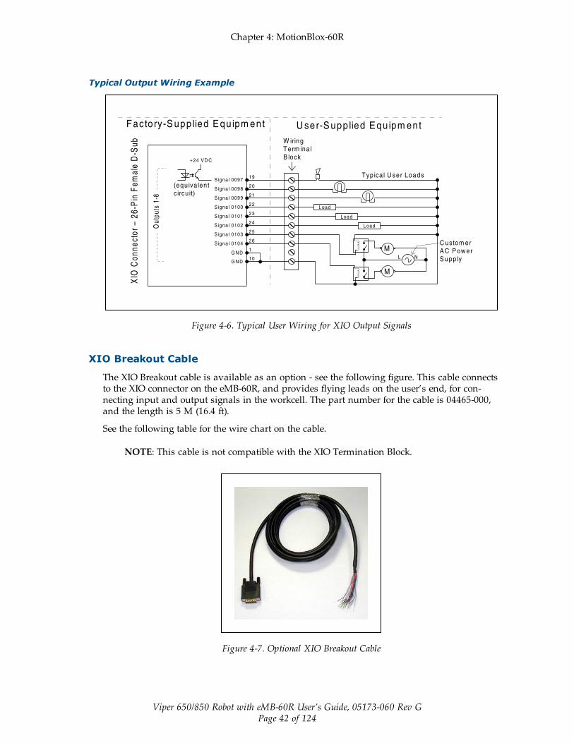
Typical Output Wiring Example
Figure 4-6. Typical User Wiring for XIO Output Signals
XIO Breakout Cable
The XIO Breakout cable is available as an option - see the following figure. This cable connectsto the XIO connector on the eMB-60R, and provides flying leads on the user’s end, for con-necting input and output signals in the workcell. The part number for the cable is 04465-000,and the length is 5 M (16.4 ft).
See the following table for the wire chart on the cable.
NOTE: This cable is not compatible with the XIO Termination Block.
Figure 4-7. Optional XIO Breakout Cable

Chapter 4: MotionBlox-60R
Viper 650/850 Robot with eMB-60R User’s Guide, 05173-060 Rev GPage 43 of 124
Table 4-10. XIO Breakout Cable Wire Chart
Pin No.Signal
Designation Wire Color Pin Locations
1 GND White
Pin 9
Pin 1
Pin 18
Pin 10Pin 19
Pin 26
26-pin male connectoron XIO Breakout Cable
2 24 VDC White/Black
3 Common 1 Red
4 Input 1.1 Red/Black
5 Input 2.1 Yellow
6 Input 3.1 Yellow/Black
7 Input 4.1 Green
8 Input 5.1 Green/Black
9 Input 6.1 Blue
10 GND Blue/White
11 24 VDC Brown
12 Common 2 Brown/White
13 Input 1.2 Orange
14 Input 2.2 Orange/Black
15 Input 3.2 Gray
16 Input 4.2 Gray/Black
17 Input 5.2 Violet
18 Input 6.2 Violet/White
19 Output 1 Pink
20 Output 2 Pink/Black
21 Output 3 Light Blue
22 Output 4 Light Blue/Black
23 Output 5 Light Green
24 Output 6 Light Green/Black
25 Output 7 White/Red
26 Output 8 White/Blue
Shell Shield

Chapter 4: MotionBlox-60R
Viper 650/850 Robot with eMB-60R User’s Guide, 05173-060 Rev GPage 44 of 124
4.6 eMB-60R DimensionsThe following figure shows dimensions of eMB-60R chassis and mounting holes.
Units in mm
0425.5
20.6
204.2
404.9
51.6
331.7
9.8
0
228.6
67.3
222.3
106.7
182.9
170.2
6X, SHCS,M4 X 6
A
B
047.6
377.8
0
7.6
45.7
129.54
C
0
32.7
197.8
0 7.6
45.7
C
0
32.7
197.8
0
7.6
45.7
C
0
47.6
377.8
0
7.6
45.7SPCD AS SHOWN, 20XM4 X 7mm DP BLIND STUDS
C
0
32.7
197.8
0
47.6
377.8
B
Note: 112 mm clearance required
in front of unit to remove amps from
box enclosure.
DC
IN 24V
GN
D
AC
200 -
240VØ
1
XBELTIO
XIO
Servo
EN
ET
EN
ET
XS
YS
TE
M
Figure 4-8. eMB-60R Mounting Dimensions
Chapter 4: MotionBlox-60R
Viper 650/850 Robot with eMB-60R User’s Guide, 05173-060 Rev GPage 45 of 124
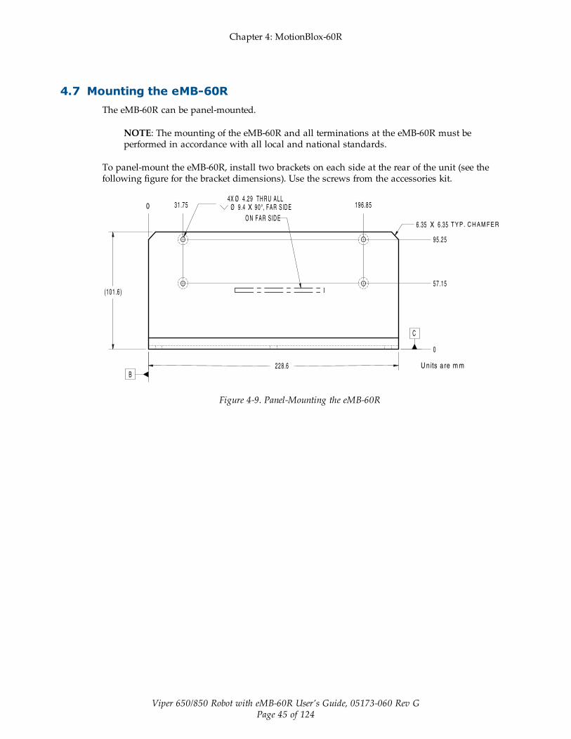
4.7 Mounting the eMB-60RThe eMB-60R can be panel-mounted.
NOTE: The mounting of the eMB-60R and all terminations at the eMB-60R must beperformed in accordance with all local and national standards.
To panel-mount the eMB-60R, install two brackets on each side at the rear of the unit (see thefollowing figure for the bracket dimensions). Use the screws from the accessories kit.
Figure 4-9. Panel-Mounting the eMB-60R


Viper 650/850 Robot with eMB-60R User’s Guide, 05173-060 Rev GPage 47 of 124
Chapter 5: System Installation
5.1 System Cables, without SmartController EXThe letters in the following figure correspond to the letters in the table of cables and parts. Thenumbers correspond to the steps in the cable installation overview table. The tables are on thepages following the figure.
DC
IN
24 VGND
AC
200 -240 V
Ø1 XB
ELT
IO
XIO Servo
ENETENETXSYSTEM
eMB-60R
24 VDC, 6 A
Power Supply
200-240 VAC
10 A
single-phase
AC Power Cable
DC Power
Cable
Front Panel
Cable
Front Panel
User-Supplied PCrunning ACE Software
T20 Adapter
Cable
XMCP Jumper Plug
XMCP
XFP
XUSR
XUSR Jumper Plug
eAIB
XSYSTEM
Cable
Robot Interface Panel
XUSR for:
- User E-Stop/Safety Gate
- Muted Safety Gate
The Jumper Plug is required if
neither of these is used
Ethernet
from PC
T20 Bypass Plug
User-Supplied
Ground Wire
T20 Pendant (option) Either T20 Pendant,T20 Bypass Plug, or
XMCP Jumper Plug must be used
2
3
4aA
B
GH
J
4a
4 4
1
5
6
7
98
L
M
Q
P
E
K
D
N
3
85 - 264 VAC
Universal
Input
Ethernet to eAIB
FP Jumper Plug
FEither Front Panel or
FP plug must be used
3a
2aC
Ethernet from eAIB
to SmartVision MX
R
9b
9a
User-supplied
Switch (option)
User-supplied
Arm Power/
Signal Cable
Viper 650Robot CN22
CN20
AIR1
AIR2
User-Supplied
Ground Wire
Grounding Terminal (M5)
DC
IN
24V GND
AC
200 -240V
Ø1 XB
ELT
IO
XIO Servo
ENETENETXSYSTEM
SmartVision MX (option)
R
S
7a
MDC Power
Cable
Camera
(option)
T
10
Optional PLC
Figure 5-1. System Cable Diagram for Viper 650/850 Robots with eMB-60R, Pendant, and Vision
The pendant is an option, and may not be present in your system. The figure includes theoptional T20 pendant and optional SmartVision MX industrial PC.

Chapter 5: System Installation
Viper 650/850 Robot with eMB-60R User’s Guide, 05173-060 Rev GPage 48 of 124
NOTE: See Installing the 24 VDC Cable on page 60 for additional system ground-ing information.
List of Cables and Parts
Open the Accessory box and locate the eAIB XSYSTEM cable. Connect the cables and peri-pherals as shown in the preceding figure. Parts and steps are covered in the following twotables.
Part Cable and Parts List Part # Part of: Notes
A eAIB XSYSTEM Cable Assembly 13323-000 std, eMB-60R
B User E-Stop, Safety Gate n/a n/a user-supplied
C XUSR Jumper Plug 04736-000 13323-000 std, eMB-60R
D Front Panel 90356-10358 standard
E Front Panel Cable 10356-10500 90356-10358
standard
F Front Panel Jumper Plug 10053-000 13323-000 std, eMB-60R
G XMCP Jumper Plug 04737-000 13323-000 std, eMB-60R
H T20 Bypass Plug 10048-000 10055-000 standard, T20
J T20 Adapter Cable 10051-003 10055-000 standard, T20
K T20 Pendant (option) 10055-000 option
L AC Power Cable (option) 04118-000 90565-010 or user-supplied
M 24 VDC Power Cable (option) 04120-000 90565-010 or user-supplied
N 24 VDC, 6 A Power Supply(option)
04536-000 90565-010 or user-supplied
P Ethernet Cable - PC -> PLC(Only while programming PLC)
n/a n/a user-supplied
Q Ethernet Cable - switch -> eMB-60R
n/a n/a user-supplied
R Ethernet Cable - switch ->SmartVision MX
n/a n/a user-supplied
S Ethernet switch, cable forSmartVision MX.
n/a n/a option,user-supplied
T Camera and cable n/a n/a option
The XUSR, XMCP, and XFP jumpers intentionally bypass safety connections so you can testthe system functionality during setup.
WARNING: Under no circumstances should you run aneCobra system, in production mode, with all three jumpersinstalled. This would leave the system with no E-Stops.

Chapter 5: System Installation
Viper 650/850 Robot with eMB-60R User’s Guide, 05173-060 Rev GPage 49 of 124
Cable Installation Overview
Power requirements for the SmartVision MX industrial PC are covered in that user guide. For24 VDC, both the eCobra robot and a SmartVision MX can usually be powered by the samepower supply.
Step Connection Part
1 Connect eAIB XSYSTEM cable to XSYSTEM on eAIB. A
2 Connect a user E-Stop or Muted Safety Gate to the eAIB XSYSTEM cableXUSR connector or
B
2a verify XUSR jumper plug is installed in eAIB XSYSTEM cable XUSR connector. C
3 Connect Front Panel cable to Front Panel and eAIB XSYSTEM cable XFP con-nector or
D, E
3a if no Front Panel, install FP jumper on eAIB XSYSTEM cable XFP connector.See NOTE after table.
F
4 Connect T20 adapter cable to eAIB XSYSTEM cable XMCP connector or J, K
4a if no T20, install XMCP jumperorT20 Adapter Cable with T20 bypass plug.
GorH
5 Connect user-supplied ground to robot. See System Installation on page 47. n/a
6 Connect 200-240 VAC to AC Input on eAIB Interface Panel; secure withclamp.
L
7 Connect 24 VDC to DC Input on Interface Panel. N, M
7a Connect 24 VDC and shield ground to SmartVision MX, if used. See SmartVi-sion MX user's guide for location.
N, M
8 Connect Ethernet cable from PC to PLC, if a PLC is used. P
9 Connect Ethernet cable from PLC to switch, if a PLC is used. S
9a Connect Ethernet cable from switch to eAIB. Q, S
9b Connect Ethernet cable from SmartVision MX, if used, to switch. R, S
10 Connect optional camera and cable to SmartVision MX, if used. T
NOTE: A front panel ships with each eCobra robot system, but you can choose notto use it if you replace its functionality with equivalent circuits. That is beyond thescope of this guide.
Chapter 5: System Installation
Viper 650/850 Robot with eMB-60R User’s Guide, 05173-060 Rev GPage 50 of 124
Optional Cables
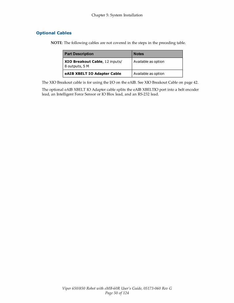
NOTE: The following cables are not covered in the steps in the preceding table.
Part Description Notes
XIO Breakout Cable, 12 inputs/8 outputs, 5 M
Available as option
eAIB XBELT IO Adapter Cable Available as option
The XIO Breakout cable is for using the I/O on the eAIB. See XIO Breakout Cable on page 42.
The optional eAIB XBELT IO Adapter cable splits the eAIB XBELTIO port into a belt encoderlead, an Intelligent Force Sensor or IO Blox lead, and an RS-232 lead.

Chapter 5: System Installation
Viper 650/850 Robot with eMB-60R User’s Guide, 05173-060 Rev GPage 51 of 124
5.2 System Cables, with SmartController EXWhen the optional SmartController EX is included in the system, the Pendant, Front Panel,and XUSR connections must connect to the SmartController EX.
SmartController EX (option)
COM1
COM2
MOUSEKEYBD
DVI
VGA
LAN1USB
LAN2USB LOUT
LIN
MIC
POWER
HDD SYS
24VCD 6A_ + Smar
tVis
ion
EX
T20 Adapter Cable
XMCP
Jumper
Plug
T20 Bypass
Plug
T20 Pendant (optional)
Either T20 Pendant, T20 Bypass
Plug, or XMCP Jumper Plug
must be used
SmartVision MX (option)
Front
Panel
Cable
Front Panel
FP
Jumper
Plug
Either Front Panel or
FP plug must be used
eMB-60R
24 VDC, 6 A Power Supply
200-240 VAC
10 A
single-phase
AC Power Cable
DC Power Cables
User-Supplied PCrunning PLC or ACEProgramming Software
eAIB XSYS Cable from
Controller XSYS Port
Ethernet from
PC to PLC,
Switch, or
SmartController EX
User-Supplied
Ground Wire
85 - 264 VAC
Universal
Input
Ethernet to
SmartController EX
User-supplied Camera (option)
User-Supplied
Ground Wire
User-Supplied
Ground Wire
Robot InterfacePanel
IEEE
1394
Arm Power
Signal Cable
DC
IN
24V GND
AC
200 -240V
Ø1 XB
ELT
IO
XIO Servo
ENETENETXSYSTEM
XUSR Jumper Plug
XUSR for:
- User E-Stop/Safety Gate
- Muted Safety Gate
- Jumper plug required
when not used
User-supplied
switch (option)
Optional PLCDC
IN
24 VGND
AC
200 -240 V
Ø1 XB
ELT
IO
XIO Servo
ENETENETXSYSTEM
D
A
E
3
1
6
8P
9
Q
3 3a
FC
2
2a
B
4a
4
4a
4
G
HJ
K
L
M
M
N
7
5
7
5b
5a
7a
10
10
1
9b
S
R
R
Viper 650 Robot
CN22
CN20
AIR1
AIR2
User-Supplied
Ground Wire
Grounding
Terminal (M5)
Figure 5-2. System Cable Diagram with SmartController EX
Installing a SmartController EX Motion Controller
Refer to the SmartController EX User’s Guide for complete information on installing the optionalSmartController EX. This list summarizes the main steps.

Chapter 5: System Installation
Viper 650/850 Robot with eMB-60R User’s Guide, 05173-060 Rev GPage 52 of 124
1. Mount the SmartController EX and Front Panel.
2. Connect the Front Panel to the SmartController EX.
3. Connect the pendant (if purchased) to the SmartController EX.
Connect a jumper plug, if no pendant is being used.
4. Connect user-supplied 24 VDC power to the controller.
Instructions for creating the 24 VDC cable, and power specification, are covered in theSmartController EX User’s Guide.
5. Install a user-supplied ground wire between the SmartController EX and ground.
List of Cables and Parts
Part Cable and Parts List Notes
A eAIB XSYS Cable standard, eAIB
B User E-Stop, Safety Gate user-supplied
C XUSR Jumper Plug standard, SmartCon-troller EX
D Front Panel standard
E Front Panel Cable standard
F Front Panel Jumper Plug standard,SmartController EX
G XMCP Jumper Plug standard,SmartController EX
H T20 Bypass Plug standard, T20
J T20 Adapter Cable standard, T20
K T20 Pendant (option) option
The following three items are available, as an option, in the powersupply/cable kit 90565-010
L AC Power Cable user-supplied/option
M 24 VDC Power Cable user-supplied/option
N 24 VDC, 6 A Power Supply user-supplied/option
P Ethernet Cable, PC -SmartController
user-supplied
Q Ethernet Cable, PC -SmartVision MX
user-supplied, option
R IEEE 1394 cable standard
S Camera and cable user-supplied, option

Chapter 5: System Installation
Viper 650/850 Robot with eMB-60R User’s Guide, 05173-060 Rev GPage 53 of 124
The XUSR, XMCP, and XFP jumpers intentionally bypass safety connections so you can testthe system functionality during setup.
WARNING: Under no circumstances should you run aneCobra system, in production mode, with all three jumpersinstalled. This would leave the system with no E-Stops.
Cable Installation Overview
Step Connection Part
1 Connect eAIB XSYS cable to XSYSTEM on eMB-60R A
2 Connect a user E-Stop or Muted Safety Gate to the XUSR connector or B
2a verify XUSR jumper plug is installed in XUSR connector. C
3 Connect Front Panel cable to Front Panel and XFP connector or D, E
3a if no Front Panel, install FP jumper on XFP connector. F
4 Connect Pendant adapter cable to XMCP connector or J, K
4a if no Pendant, install XMCP jumper or bypass plug. G orH
5 Connect user-supplied ground to robot. See robot user's guide for location. n/a
5a Connect user-supplied ground to SmartController EX. See SmartControllerEX user's guide for location.
n/a
5b Connect user-supplied ground to SmartVision MX, if used. See SmartVision MXuser's guide for location.
n/a
6 Connect 200-240 VAC to AC Input on eAIB; secure with clamp. L
7 Connect 24 VDC to DC Input on eAIB and SmartController EX. N,M
7a Connect 24 VDC to SmartVision MX, if used. N,M
8 Connect Ethernet cable from PC to SmartController EX. P
9a Connect Ethernet cable to SmartVision MX, if used. Q
10 Connnect IEEE 1394 cable between SmartController EX and eAIB SmartServo R
11 Connect optional camera and cable to SmartVision MX, if used. S

Chapter 5: System Installation
Viper 650/850 Robot with eMB-60R User’s Guide, 05173-060 Rev GPage 54 of 124
Optional Cables
NOTE: The following cables are not covered in the steps in the preceding table.
Part Description Notes
XIO Breakout Cable, 12 inputs/8 outputs, 5 M
Available as option
Y Cable, for XSYS cable connections todual robots
Available as option withSmartController EX
eAIB XBELT IO Adapter Cable Available as option
The XIO Breakout cable is for using the I/O on the eAIB. See XIO Breakout Cable on page 42.
The Y cable attaches at the SmartController EX XSYS connector, and splits it into two XSYSconnectors. This is part number 00411-000. See the Dual Robot Configuration Guide.
The optional eAIB XBELT IO Adapter cable splits the eAIB XBELTIO port into a belt encoderlead, an Intelligent Force Sensor or IO Blox lead, and an RS-232 lead. If the system has aSmartController EX, this is only needed for Intelligent Force Sensing.

Chapter 5: System Installation
Viper 650/850 Robot with eMB-60R User’s Guide, 05173-060 Rev GPage 55 of 124
5.3 System Cables, with Two Conveyor Encoders
DC
IN
24 VGND
AC
200 -240 V
Ø1 XB
ELT
IO
XIO Servo
ENETENETXSYSTEM
eMB-60R
24 VDC, 6 A Power Supply 200-240 VAC 10 A single-phase
AC Power
Cable
DC Power
Cable
Front Panel
Cable
Front Panel
User-Supplied PCrunning ACE Software
T20 Adapter
Cable
XMCP Jumper Plug
XMCP
XFP
XUSR
XUSR Jumper Plug
eAIB
XSYSTEM
Cable
Robot Interface Panel
XUSR for:
- User E-Stop/Safety Gate
- Muted Safety Gate
The Jumper Plug is required if
neither of these is used
Ethernet
from PC
T20 Bypass Plug
User-Supplied
Ground Wire
T20 Pendant (option) Either T20 Pendant,T20 Bypass Plug, or
XMCP Jumper Plug must be used
2
3
4a
A
B
GH
J
4a
4 4
1
5
6
7
8
L
M
Q
E
K
D
N
3
85 - 264 VAC
Universal
Input
Ethernet to eAIB
FP Jumper Plug
FEither Front Panel or
FP plug must be used
3a
2aC
XBELTIO - Belt/Force/RS232
Belt Y-Splitter
to Belt Encoder 1
to Belt Encoder 2
Belt Branch
8
10
Arm Power/
Signal Cable
Viper 650 Robot
CN22
CN20
AIR1
AIR2
User-Supplied
Ground Wire
Grounding
Terminal (M5)
DC
IN
24V GND
AC
200 -240V
Ø1 XB
ELT
IO
XIO Servo
ENETENETXSYSTEM
XBELT IO
13463-000
HDB26FEMALE
BEL
TEN
CO
DER
FOR
CE/
EXPI
OR
S232
BELT ENC.09443-000
DB15FEMALE
12
Figure 5-3. System Cable Diagram with Belt Encoders

Chapter 5: System Installation
Viper 650/850 Robot with eMB-60R User’s Guide, 05173-060 Rev GPage 56 of 124
Pinouts for eAIB XBELT IO Adapter
Belt Encoder
:NOITPIRCSED:OT :MORFBELT ENC - PIN 15 HDB26 - PIN 2 B_ENC_A1+BELT ENC - PIN 7 HDB26 - PIN 3 B_ENC_A1-BELT ENC - PIN 14 HDB26 - PIN 11 B_ENC_B1+BELT ENC - PIN 6 HDB26 - PIN 12 B_ENC_B1-BELT ENC - PIN 13 HDB26 - PIN 19 B_ENC_Z1+BELT ENC - PIN 5 HDB26 - PIN 20 B_ENC_Z1-BELT ENC - PIN 11 HDB26 - PIN 4 B_ENC_A2+BELT ENC - PIN 3 HDB26 - PIN 5 B_ENC_A2-BELT ENC - PIN 10 HDB26 - PIN 13 B_ENC_B2+BELT ENC - PIN 2 HDB26 - PIN 14 B_ENC_B2-BELT ENC - PIN 9 HDB26 - PIN 21 B_ENC_Z2+BELT ENC - PIN 1 HDB26 - PIN 22 B_ENC_Z2-BELT ENC - PIN 4 HDB26 - PIN 1 BELT_5VBELT ENC - PIN 12 HDB26 - PIN 10 GNDBELT ENC - SHELL HDB26 - SHELL SHIELD
RS232
DXT_232SR52 NIP- 62BDH3 NIP- 232SRDXR_232SR62 NIP- 62BDH2 NIP– 232SR
DNG81 NIP- 62BDH 5 NIP– 232SRDLEIHSLLEHS– 62BDHLLEHS– 232SR
FORCE/EXPIO
:NOITPIRCSED:62BD OIPXE OT:1PJ+ KLC7 NIP- 62BDH5 NIP- 1PJ- KLC8 NIP- 62BDH 4 NIP- 1PJ
V5_TLEB6 NIP- 62BDH6 NIP- 1PJDNG51 NIP- 62BDH1 NIP– 1PJ
+ATAD61 NIP- 62BDH3 NIP– 1PJ-ATAD71 NIP- 62BDH 2 NIP– 1PJDLEIHSLLEHS- 62BDHLLEHS 9BD
5.4 ACE Software
User-supplied PC
The user loads the ACE software onto the PC and connects it to the eMB-60R via an Ethernetcable. Depending on the other equipment in the system, there may be an Ethernet switchbetween the two.
Installing ACE Software
The ACE software is installed from the ACE software disk.

Chapter 5: System Installation
Viper 650/850 Robot with eMB-60R User’s Guide, 05173-060 Rev GPage 57 of 124
1. Insert the disk into the disk drive of your PC.
If Autoplay is enabled, the ACE software menu is displayed. If Autoplay is disabled,you will need to manually start the disk.
2. Especially if you are upgrading your ACE software installation: from the ACE softwaredisk menu, click Read Important Information.
3. From the ACE software disk menu, select:
Install the ACE Software
The ACE Setup wizard opens.
4. Follow the online instructions as you step through the installation process.
5. When the installation is complete, click Finish.
6. After closing the ACE Setup wizard, click Exit on the disk menu to close the menu.
NOTE: You will have to restart the PC after installing ACE software.
5.5 Connecting Cables from the eMB-60R to the RobotThe cable between the robot and the eMB-60R is called the Arm Power/Signal cable.
1. Connect one end of the Arm Power/Signal cable to the CN22 connector on the back plateof the robot. Tighten the thumb-screw securely.
2. Connect the other end of the cable to the large, circular connector on the eMB-60R. SeeSystem Cable Diagram for Viper 650/850 Robots with eMB-60R, Pendant, and Vision onpage 47.
WARNING: Verify that all connectors are fully-inserted andscrewed down. Failure to do this could cause unexpectedrobot motion. Also, a connector could get pulled out or dis-lodged unexpectedly.

Chapter 5: System Installation
Viper 650/850 Robot with eMB-60R User’s Guide, 05173-060 Rev GPage 58 of 124
5.6 Connecting 24 VDC Power to eMB-60R Servo Controller
Specifications for 24 VDC Power
Table 5-1. Specifications for 24 VDC User-Supplied Power Supply
Customer-Supplied Power Supply 24 VDC (± 10%), 150 W (6 A)(21.6 V< Vin< 26.4 V)
Circuit Protection1 Output must be less than 300 W peakor
8 Amp in-line fuse
Power Cabling 1.5 – 1.85 mm² (16-14 AWG)
Shield Termination Cable shield connected to frame ground onpower supply and ground point oneMB-60R. See User-Supplied 24 VDC Cableon page 60.
1User-supplied 24 VDC power supply must incorporate overload protection to limit peakpower to less than 300 W, or 8 A in-line fuse protection must be added to the 24 V powersource.
NOTE: Fuse information is located on the eMB-60R electronics.
The power requirements for the user-supplied power supply will vary depending on the con-figuration of the robot and connected devices. We recommend a 24 V, 6 A power supply toallow for startup current draw and load from connected user devices, such as digital I/O loads.
CAUTION: Make sure you select a 24 VDC power supplythat meets the specifications in the preceding table. Usingan underrated supply can cause system problems and pre-vent your equipment from operating correctly. See the fol-lowing table for a recommended power supply.
Table 5-2. Recommended 24 VDC Power Supply
Vendor Name Model Ratings Mount
OMRON S8JX-G15024C 24 VDC, 6.5 A, 150 W Front Mount
OMRON S8JX-G15024CD 24 VDC, 6.5 A, 150 W DIN-Rail Mount

Chapter 5: System Installation
Viper 650/850 Robot with eMB-60R User’s Guide, 05173-060 Rev GPage 59 of 124
Details for 24 VDC Mating Connector
The 24 VDC mating connector and two pins are supplied with each system. They are shippedin the cable/accessories box.
Table 5-3. 24 VDC Mating Connector Specs
Connector Details Connector receptacle, 2 position, type:Molex Saber, 18 A, 2-Pin
Molex P/N 44441-2002
Digi-Key P/N WM18463-ND
Pin Details Molex connector crimp terminal,female, 14-18 AWG
Molex P/N 43375-0001
Digi-Key P/N WM18493-ND
Recommended crimping tool, Molex Hand Crim-per
Molex P/N 63811-0400
Digi-Key P/N WM9907-ND
NOTE: The 24 VDC cable is not supplied with the system, but is available in theoptional Power Cable kit. See List of Cables and Parts on page 48.
Procedure for Creating 24 VDC Cable
1. Locate the connector and pins from the preceding table.
2. Use shielded two-conductor cable with 14-16 AWG wire to create the 24 VDC cable.Select the wire length to safely reach from the user-supplied 24 VDC power supply tothe eMB-60R base.
NOTE: You also must create a separate 24 VDC cable for the SmartCon-troller. That cable uses a different style of connector. See the SmartControllerUser’s Guide.
3. Crimp the pins onto the wires using the recommended crimping tool.
4. Insert the pins into the connector. Confirm that the +24 V and ground wires are in thecorrect terminals in the plug.
5. Install a user-supplied ring lug (for an M3 screw) on the shield at the eMB-60R end ofthe cable.

Chapter 5: System Installation
Viper 650/850 Robot with eMB-60R User’s Guide, 05173-060 Rev GPage 60 of 124
6. Prepare the opposite end of the cable for connection to the user-supplied 24 VDC powersupply, including a terminal to attach the cable shield to frame ground.
Installing the 24 VDC Cable
Do not turn on the 24 VDC power until instructed to do so in the next chapter.
1. Connect one end of the shielded 24 VDC cable to your user-supplied 24 VDC power sup-ply. See User-Supplied 24 VDC Cable on page 60. The cable shield should be connectedto frame ground on the power supply.
2. Plug the mating connector end of the 24 VDC cable into the 24 VDC connector on theinterface panel on the back of the eMB-60R. The cable shield should be connected to theground point on the interface panel.
–+
24 V, 6 A
Frame Ground
24 V, 5 A–+
User-Supplied
Power Supply
24 VDC
eMB-60R
Servo Controller
User-Supplied Shielded
Power Cable
- +
SmartController EX
(Option)
User-Supplied Shielded
Power CableAttach shield from user-supplied
cable to controller using
star washer and M3 x 6 screw.
Attach shield from user-
supplied cables to frame
ground on power supply.
Attach shield from user-
supplied cable to ground
screw on eMB-60R Interface
Panel.
–GND
+
Figure 5-4. User-Supplied 24 VDC Cable
NOTE: We recommend that DC power be delivered over shielded cables, with theshield connected to frame ground at the power supply, and to the ground pointsshown in the diagram above for the eMB-60R and SmartController. The length ofthe wire from the cable shield to the ground points should be less than 50 mm.

Chapter 5: System Installation
Viper 650/850 Robot with eMB-60R User’s Guide, 05173-060 Rev GPage 61 of 124
5.7 Connecting 200-240 VAC Power to eMB-60RWARNING: Ensure compliance with all local and nationalsafety and electrical codes for the installation and operationof the robot system.
WARNING: Appropriately-sized Branch Circuit Protectionand Lockout / Tagout Capability must be provided inaccordance with the National Electrical Code and any localcodes.
Specifications for AC Power
Table 5-4. Specifications for 200/240 VAC User-Supplied Power Supply
Auto-RangingNominalVoltageRanges
MinimumOperatingVoltage1
MaximumOperatingVoltage
Frequency/Phasing
RecommendedExternal CircuitBreaker, User-Supplied
200 to 240 V 180 V 264 V 50/60 Hz1-phase
10 Amps
1Specifications are established at nominal line voltage. Low line voltage can affect robot per-formance.
The robot system is intended to be installed as a piece of equipment in a per-manently-installed system.
Table 5-5. Typical Robot Power Consumption1
Robot Move Average Power Peak Power2
Viper 650 No load - Adept cycle3 371 W 947 W
5.0 kg - Adept cycle3 477 W 1526 W
5.0 kg - all joints move 834 W 2088 W
Viper 850 No load - Adept cycle3 358 W 1237 W
5.0 kg - Adept cycle3 407 W 1202 W
5.0 kg - all joints move 704 2090
1Typical power data is with 220 VAC, 60 Hz, 1-phase nominal input.
2For short durations (100 ms).
3Adept cycle:The robot tool performs continuous path, straight-line motions 25 mm (1in.) up, 305 mm (12 in.) over, 25 mm (1 in.) down, and back along the same path, at20° C ambient. COARSE is enabled and BREAKs are used at each end location. Notachievable over all paths.

Chapter 5: System Installation
Viper 650/850 Robot with eMB-60R User’s Guide, 05173-060 Rev GPage 62 of 124
DANGER: AC power installation must be performed by a skilledand instructed person - refer to the Robot Safety Guide. During install-ation, unauthorized third parties must be prevented from turningon power through the use of fail-safe lockout measures, as man-dated by ISO 10218-1, Clause 5.2.4.
Failure to use appropriate power (less than or more than the ratedvoltage range of 200-240 VAC) can lead to malfunction or failuresof the robot or hazardous situations.
Facility Overvoltage Protection
The user must protect the robot from excessive overvoltages and voltage spikes. If the countryof installation requires a CE-certified installation, or compliance with IEC 1131-2, the followinginformation may be helpful: IEC 1131-2 requires that the installation must ensure thatCategory II overvoltages (i.e., line spikes not directly due to lightning strikes) are not exceeded.Transient overvoltages at the point of connection to the power source shall be controlled not toexceed overvoltage Category II, i.e., not higher than the impulse voltage corresponding to therated voltage for the basic insulation. The user-supplied equipment or transient suppressorshall be capable of absorbing the energy in the transient.
In the industrial environment, nonperiodic over-voltage peaks may appear on mains powersupply lines as a result of power interruptions to high-energy equipment (such as a blown fuseon one branch in a 3-phase system). This will cause high-current pulses at relatively lowvoltage levels. The user shall take the necessary steps to prevent damage to the robot system(such as by interposing a transformer). See IEC 1131-4 for additional information.
AC Power Diagrams
E
E
N
N
L
L
F1 10A
eMB-60R
1Ø 200–240 VAC
User-Supplied AC Power Cable
Note: F1 is user-supplied, must be slow blow.
1Ø
200–240 VAC
20A
L = LineN = NeutralE = Earth Ground
Figure 5-5. Typical AC Power Installation with Single-Phase Supply

Chapter 5: System Installation
Viper 650/850 Robot with eMB-60R User’s Guide, 05173-060 Rev GPage 63 of 124
E
E
N
L3
L
L1
L2F5 10A
F4 10A
eMB-60R
1Ø 200–240 VAC
User-Supplied AC Power Cable
Note: F4 and F5 are user-supplied, must be slow blow.
3Ø
200–240 VAC
L = Line 1N = Line 2E = Earth Ground
200–240 VAC
Figure 5-6. Single-Phase Load across L1 and L2 of a Three-Phase Supply
Details for AC Mating Connector
The AC mating connector is supplied with each system. It is shipped in the cable/accessoriesbox. The supplied plug is internally labeled for the AC power connections (L, E, N).
Table 5-6. AC Mating Connector Details
AC Connector details AC in-line power plug, straight,female, screw terminal, 10 A,250 VAC
Qualtek P/N 709-00/00
Digi-Key P/N Q217-ND
NOTE: The AC power cable is not supplied with the system, but is available in theoptional Power Cable kit.
Procedure for Creating 200-240 VAC Cable
1. Locate the AC mating connector shown in the preceding table.
2. Open the connector by unscrewing the screw on the shell and removing the cover.
3. Loosen the two screws on the cable clamp. See AC Power Mating Connector on page 64.
4. Use 18 AWG wire to create the AC power cable. Select the wire length to safely reachfrom the user-supplied AC power source to the eMB-60R base.
5. Strip approximately 18 to 24 mm of insulation from each of the three wires.

Chapter 5: System Installation
Viper 650/850 Robot with eMB-60R User’s Guide, 05173-060 Rev GPage 64 of 124
6. Insert the wires into the connector through the removable bushing.
7. Connect each wire to the correct terminal screw, and tighten the screw firmly.
8. Tighten the screws on the cable clamp.
9. Replace the cover and tighten the screw to seal the connector.
10. Prepare the opposite end of the cable for connection to the facility AC power source.
Figure 5-7. AC Power Mating Connector
Installing AC Power Cable to eMB-60R
1. Connect the unterminated end of the AC power cable to your facility AC power source.See Figure 5-5. and Figure 5-6.
Do not turn on AC power at this time.
2. Plug the AC connector into the AC power connector on the interface panel on theeMB-60R.
3. Secure the AC connector with the locking latch.
5.8 Grounding the Robot SystemProper grounding is essential for safe and reliable robot operation. Follow these recom-mendations to properly ground your robot system.
WARNING: Wiring must be performed by authorized or cer-tified personnel. Failure to observe this precaution may res-ult in fire or electric shock.
NOTE: Ground the grounding terminal of the robot with a wire of 12 AWG or lar-ger. Ground resistance must be ≤ 10 Ω.
NOTE: Use a dedicated grounding wire and grounding electrode. Do not sharethem with any other electric power or power equipment, such as a welder.

Chapter 5: System Installation
Viper 650/850 Robot with eMB-60R User’s Guide, 05173-060 Rev GPage 65 of 124
Ground Point on Robot Base
The user can install a protective earth ground wire at the robot base to ground the robot. Seethe following figure. The user is responsible for supplying the ground wire to connect to pro-tective earth ground.
CN22
CN20
AIR1
AIR2
Grounding
Terminal (M5)
Ground Label
Figure 5-8. Ground Point on Robot Base
Ground Point on MotionBlox-60R
The user can install a ground wire at the eMB-60R chassis. Use the hole below the eMB-60Rinterface panel. See the following figure. The user should provide a ground wire and use theprovided M4 screw and external tooth lock washer to connect to earth ground. Make sure totighten the screw on the ground wire to create a proper ground connection. Optionally, twotapped holes are provided to attach user-supplied strain relief.
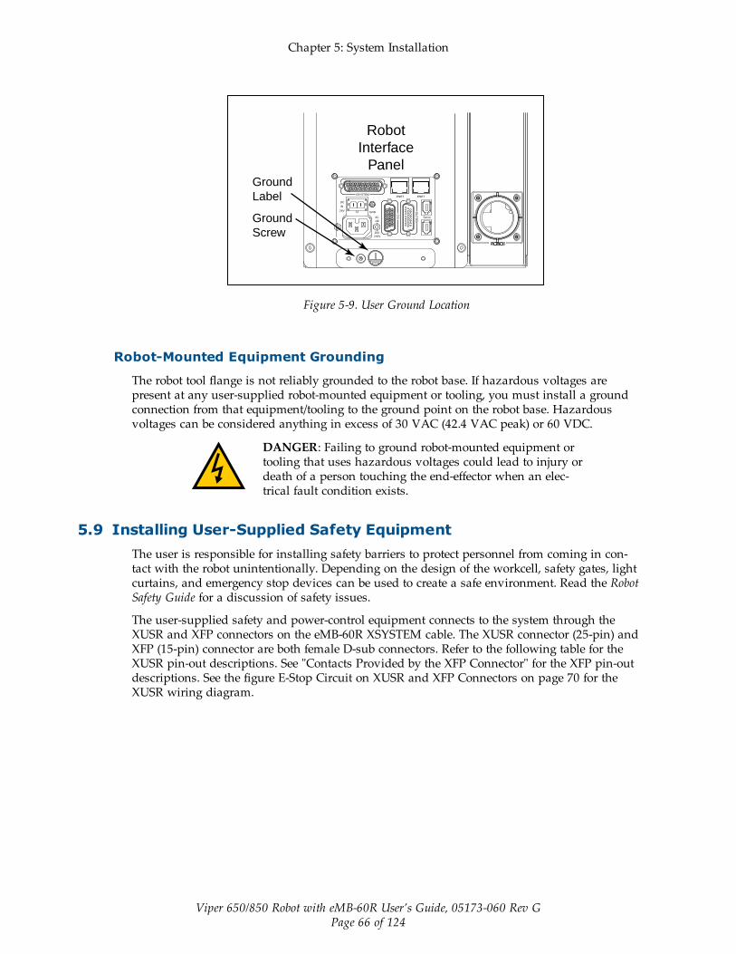
Chapter 5: System Installation
Viper 650/850 Robot with eMB-60R User’s Guide, 05173-060 Rev GPage 66 of 124
DC
IN
24VGND
AC
200 -
240V
Ø1
XB
ELT
IO
XIO Servo
ENETENETXSYSTEM
Robot
Interface
Panel
Ground
Screw
Ground
Label
Figure 5-9. User Ground Location
Robot-Mounted Equipment Grounding
The robot tool flange is not reliably grounded to the robot base. If hazardous voltages arepresent at any user-supplied robot-mounted equipment or tooling, you must install a groundconnection from that equipment/tooling to the ground point on the robot base. Hazardousvoltages can be considered anything in excess of 30 VAC (42.4 VAC peak) or 60 VDC.
DANGER: Failing to ground robot-mounted equipment ortooling that uses hazardous voltages could lead to injury ordeath of a person touching the end-effector when an elec-trical fault condition exists.
5.9 Installing User-Supplied Safety EquipmentThe user is responsible for installing safety barriers to protect personnel from coming in con-tact with the robot unintentionally. Depending on the design of the workcell, safety gates, lightcurtains, and emergency stop devices can be used to create a safe environment. Read the RobotSafety Guide for a discussion of safety issues.
The user-supplied safety and power-control equipment connects to the system through theXUSR and XFP connectors on the eMB-60R XSYSTEM cable. The XUSR connector (25-pin) andXFP (15-pin) connector are both female D-sub connectors. Refer to the following table for theXUSR pin-out descriptions. See "Contacts Provided by the XFP Connector" for the XFP pin-outdescriptions. See the figure E-Stop Circuit on XUSR and XFP Connectors on page 70 for theXUSR wiring diagram.

Chapter 5: System Installation
Viper 650/850 Robot with eMB-60R User’s Guide, 05173-060 Rev GPage 67 of 124
Table 5-7. Contacts Provided by the XUSR Connector
PinPairs
Description Comments
Voltage-Free Contacts Provided by Customer
1, 14 User E-Stop CH 1 (mushroompush-button, safety gates, etc.)
N/C contacts, Shorted if NOT Used
2, 15 User E-Stop CH 2 (same as pins1, 14)
N/C contacts, Shorted if NOT Used
3, 16 Line E-Stop (used for otherrobot or assembly line E-Stopinterconnection. Does not affectE-Stop indication (pins 7, 20))
N/C contacts, Shorted if NOT Used
4, 17 Line E-Stop (same as pins 3,16)
N/C contacts, Shorted if NOT Used
5, 18 Muted safety gate CH 1 (causesE-Stop in Automatic mode only)
N/C contacts, Shorted if NOT Used
6, 19 Muted Safety Gate CH 2 (sameas pins 5, 18)
N/C contacts, Shorted if NOT Used
Voltage-Free Contacts provided by Viper
7, 20 E-Stop indication CH 1 Contacts are closed when Front Panel,pendant, and customer E-Stops are nottripped
8, 21 E-Stop indication CH 2 (same aspins 7, 20)
Contacts are closed when Front Panel,pendant, and customer E-Stops are nottripped
9, 22 Manual/Automatic indication CH1
Contacts are closed in Automatic mode
10, 23 Manual/Automatic indication CH2
Contacts are closed in Automatic mode
11, 12,13, 24,25
No connection

Chapter 5: System Installation
Viper 650/850 Robot with eMB-60R User’s Guide, 05173-060 Rev GPage 68 of 124
Table 5-8. Contacts Provided by the XFP Connector
PinPairs
Description Requirements for User-Supplied Front Panel
Voltage-Free Contacts Provided by Customer
1, 9 Front Panel E-Stop CH 1 User must supply N/C con-tacts
2, 10 Front Panel E-Stop CH 2 User must supply N/C con-tacts
3, 11 Remote Manual/Automatic switch CH 1.Manual = Open Automatic = Closed
Optional - jumper closed forAuto Mode-only operation
4, 12 Remote Manual/Automatic switch CH 2.Manual = Open Automatic = Closed
Optional - jumper closed forAuto Mode-only operation
6, 14 Remote High Power on/off momentary push-but-ton
User must supply moment-ary push-button to enableHigh Power to system
Non-voltage-Free Contacts
5, 13 System-Supplied 5 VDC andGND for High PowerOn/Off Switch Lamp
User must supply lamp, oruse 1 W, 47 ohm resistor -system will not operate if notpresent
7, 15a Controller system 5 V power on LED, 5 V, 20 mA Optional - indicator only
8 No connection
Pin 1Pin 8
Pin 9Pin 15
XFP
See the figure Front Panel Schematic on page 71 for a schematic diagram of the Front Panel.
aUsers must exercise caution to avoid inadvertently connecting 24 V signals to these pins,because this will damage the electronics.
NOTE: The system was evaluated by Underwriters Laboratory with a Front Panel.Using a substitute front panel could void UL compliance.
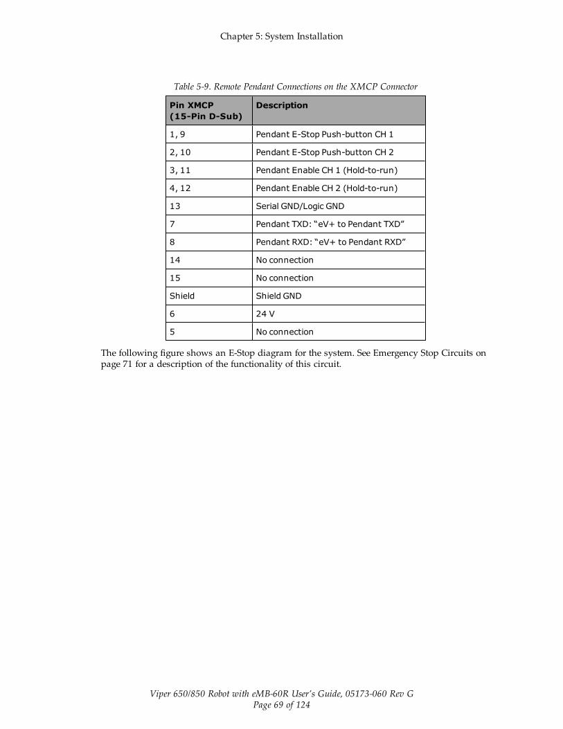
Chapter 5: System Installation
Viper 650/850 Robot with eMB-60R User’s Guide, 05173-060 Rev GPage 69 of 124
Table 5-9. Remote Pendant Connections on the XMCP Connector
Pin XMCP(15-Pin D-Sub)
Description
1, 9 Pendant E-Stop Push-button CH 1
2, 10 Pendant E-Stop Push-button CH 2
3, 11 Pendant Enable CH 1 (Hold-to-run)
4, 12 Pendant Enable CH 2 (Hold-to-run)
13 Serial GND/Logic GND
7 Pendant TXD: “eV+ to Pendant TXD”
8 Pendant RXD: “eV+ to Pendant RXD”
14 No connection
15 No connection
Shield Shield GND
6 24 V
5 No connection
The following figure shows an E-Stop diagram for the system. See Emergency Stop Circuits onpage 71 for a description of the functionality of this circuit.
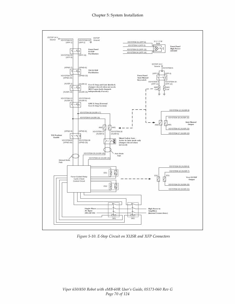
Chapter 5: System Installation
Viper 650/850 Robot with eMB-60R User’s Guide, 05173-060 Rev GPage 70 of 124
ES1ES2
ESTOP 24 V
Source XSYSTEM-31
(XFP-1)
XSYSTEM-20
(XFP-9)
(XPND-7)
XSYSTEM-24
(XPND-24)
(XUSR-1)
(XUSR-14)
XSYSTEM-13
(XUSR-3)
(XPND-9)
T20 Pendant
Enable
XSYSTEM-8
(XPND-26)
Manual Mode
Path
Force-Guided Relay
Cyclic Check
Control Circuit
Single-Phase
AC Input
200-240 VAC
Front Panel
ESTOP
Pushbutton
T20 ESTOP
Pushbutton
User E-Stop and Gate Interlock
(Jumper closed when not used,
MUST open both channels
independently if used.)
LINE E-Stop (External
User E-Stop System)
Muted Safety Gate -
Active in Auto mode only
(Jumper closed when
not used)
Front Panel
Auto/Manual
Keyswitch
High Power to
Amplifiers
(Internal Connections)
Front Panel
High Power
ON/OFF
Auto/Manual
Output
User ESTOP
Output
XSYSTEM-32
(XFP-2)
ESTOP
Ground
(XFP-10)
(XPND-6)
(XPND-23)
(XUSR-2)
(XUSR-15)
XSYSTEM-43
(XUSR-4)
XSYSTEM-39 (XUSR-17)
XSYSTEM-9 (XUSR-16)
(XPND-8)
XSYSTEM-38
(XPND-25)
XSYSTEM-29 (XUSR-18)
XSYSTEM-44 (XUSR-19)
ES1
ES2
SR1 SR2
AM2 AM1
XSYSTEM-14
(XUSR-5)
XSYSTEM-30
(XUSR-6)
Auto Mode
Path
XSYSTEM-33 (XFP-13)
6 V, 1.2 W
BulbXSYSTEM-3 (XFP-5)
XSYSTEM-31 (XFP-6)
XSYSTEM-34 (XFP-14)
ESTOP 24 V
SourceXSYSTEM-5
(XFP-4)(XFP-3)
XSYSTEM-19
(XFP-12)
XSYSTEM-4
(XFP-11)
AM2
Coil
AM1
Coil
XSYSTEM-12 (XUSR-9)
XSYSTEM-28 (XUSR-10)
AM2 AM1
XSYSTEM-42 (XUSR-23)
XSYSTEM-27 (XUSR-22)
XSYSTEM-26 (XUSR-8)
XSYSTEM-10 (XUSR-7)
XSYSTEM-25 (XUSR-20)
XSYSTEM-40 (XUSR-21)
Figure 5-10. E-Stop Circuit on XUSR and XFP Connectors

Chapter 5: System Installation
Viper 650/850 Robot with eMB-60R User’s Guide, 05173-060 Rev GPage 71 of 124
ESTOPSRC
24 VS
5 VD
D
SYSPWRLT 7
6
5
4
2
3
1
17
16
8
10
9
11
12
13
14
15
XFP15PDSUBM
MANUALSRC1
HIPWRREQ
MANUALRLY2
MANUALRLY1
HIPWRLT
ESTOPFP2
ESTOPFP1
HPLT5V
NC
MANUALSRC2
"MANUAL/AUTO""System Power LED"
MANUALSRC1
SW1
MANUALRLY2
MANUALRLY1
MANUALSRC224 VS
"HIGH POWER ON/OFF"
SWL1
HIPWRREQ
HPLT5 V
HIPWRLT
D
ESTOPSRC
"EMERGENCY STOP"
SW2
ESTOPFP2
ESTOPFP1
5 VD
D2-PIN_MINI
SYSPWRLT
Front Panel Schematic
Figure 5-11. Front Panel Schematic
Emergency Stop Circuits
The eMB-60R XSYSTEM cable provides connections for Emergency Stop (E-Stop) circuits onthe XUSR and XFP connectors. This gives the controller system the ability to duplicate E-Stopfunctionality from a remote location using voltage-free contacts. See Figure 5-10.
The XUSR connector provides external two-channel E-Stop input on pin pairs 1, 14 and 2, 15.The XFP connector provides two-channel E-Stop input on pin pairs 1, 9 and 2, 10.
NOTE: These pins must be shorted if not used. Both channels must open inde-pendently if used. Although an Emergency Stop will occur, the controller will flagan error state if one channel is jumpered closed and the other channel is opened. Itwill also flag an error state if the channels are shorted together.
User E-Stop Indication Contacts - Remote Sensing of E-Stop
These contacts provide a method to indicate the status of the ESTOP chain, inclusive of theFront Panel Emergency Stop push-button, the pendant Emergency Stop push-button, and theUser Emergency Stop Contacts.

Chapter 5: System Installation
Viper 650/850 Robot with eMB-60R User’s Guide, 05173-060 Rev GPage 72 of 124
NOTE: These contacts do not indicate the status of any connections below the UserE-Stop contacts. Thus, they will NOT indicate the status of the Line E-Stop, MCPENABLE, or the Muted Safety gate. If you have a specific need in this area, contactOmron Adept Technologies, Inc. for information on alternate indicating modes.
Two pairs of pins on the XUSR connector (pins 7, 20 and 8, 21) provide voltage-free contacts,one for each channel, to indicate whether the E-Stop chain, as described above, on that channelis closed. Both switches are closed on each of the redundant circuits in normal operation (noE-Stop). The user may use these contacts to generate an E-Stop for other equipment in the work-cell. The load on the contacts must not exceed 40 VDC or 30 VAC at a maximum of 1 A.
These voltage-free contacts are provided by a redundant, cyclically-checked, positive-drive,safety relay circuit for Category 3 PL-d per ISO 13849 operation (see Figure 5-10. and the tableContacts Provided by the XFP Connector on page 68 for the customer E-Stop circuitry).
Line E-Stop Input
The XUSR connector on the controller contains a two-channel Line E-Stop input for workcell orother equipment emergency-stop inputs. Generally, the customer E-Stop Indication contact out-puts are used to generate an emergency stop in such external equipment. Thus, if one were towire the same equipment’s outputs into the customer E-Stop input (that is, in series with thelocal robot’s E-Stop push-buttons), a lock-up situation could occur.
The Line E-Stop input comes into the circuit at a point where it cannot affect the customer E-Stop indication relays and will not cause such a lock-up situation. For any situation where twosystems should be cross-coupled, for example, the customer E-Stop indication of one controlleris to be connected to the input of another controller, the Line E-Stop input is the point to bringin the other controller’s output contacts. See the figure E-Stop Circuit on XUSR and XFP Con-nectors on page 70 for more information.
Do not use the Line E-Stop for such devices as local E-Stop push-buttons, since their statusshould be reported to the outside on the local user E-Stop indication output contact while theLine E-Stop inputs will not.
Muted Safety Gate E-Stop Circuitry
Two pairs of pins on the XUSR connector (pins 5, 18 and 6, 19) provide connections for asafety gate designed to yield an E-Stop allowing access to the workspace of the robot inManual mode only, not in Automatic mode. It is up to the customer to determine if teachingthe robot in Manual Mode, by a skilled programmer (See Qualification of Personnel in theRobot Safety Guide), wearing safety equipment and carrying a pendant, is allowable under localregulations. The E-Stop is said to be “muted” in Manual mode (for the customer E-Stop cir-cuitry, see the figures and tables at the beginning of this section).
The muted capability is useful for a situation where a shutdown must occur if the cell gate isopened in Automatic mode, but you need to open the gate in Manual mode. If the mute gate isopened in Automatic mode, the robot defaults to Manual mode operation when power is re-enabled. In muted mode, the gate can be left open for personnel to work in the robot cell.However, safety is maintained because of the speed restriction.
WARNING: Whenever possible, manual mode operations should beperformed with all personnel outside the workspace.

Chapter 5: System Installation
Viper 650/850 Robot with eMB-60R User’s Guide, 05173-060 Rev GPage 73 of 124
CAUTION: If you want the cell gate to always cause a robot shut-down, wire the gate switch contacts in series with the user E-Stopinputs. Do not wire the gate switch into the muted safety gate inputs.
Remote Manual Mode
The Front Panel provides for a Manual Mode circuit. See Remote High Power On/Off Controlon page 73 for further details about the customer Remote Manual Mode circuitry.
The Front Panel, or the user-supplied panel, must be incorporated into the robot workcell toprovide a “Single Point of Control” (the pendant) when the controller is placed in Manualmode. Certain workcell devices, such as PLCs or conveyors, may need to be turned off whenthe operating mode switch is set to Manual mode. This is to ensure that the robot controllerdoes not receive commands from devices other than from the pendant, the single point of con-trol.
If the user needs to control the Manual/Automatic mode selection from other control equip-ment, then a custom splitter cable or complete replacement of the Front Panel may be required.See Front Panel Schematic on page 71. In this situation, a pair of contacts should be wired inseries with the Front Panel Manual/Automatic mode contacts. Thus, both the Front Panel andthe customer contacts need to be closed to allow Automatic mode.
WARNING: Do not wire user-supplied Manual/Automatic contactsin parallel with the Front Panel switch contact. This would violatethe “Single Point of Control” principle and might allow Automatic(high-speed) mode to be selected while an operator is in the cell.
User Manual/Auto Indication
Two pairs of pins on the XUSR connector (pins 9, 22 and 10, 23) provide a voltage-freecontact to indicate whether the Front Panel and/or remote Manual/Automatic switches areclosed. The user may use these contacts to control other mechanisms (for example, conveyor,linear modules, etc.) when Manual mode is selected. The load on the contacts should notexceed 40 VDC or 30 VAC at a maximum of 1 A.
WARNING: Any safeguards that were suspended shall be returnedto full functionality prior to selecting Automatic Mode.
User High Power On Indication
In the optional SmartController EX, eV+ controls a normally-open relay contact on the XDIOconnector (pins 45, 46, see the table XDIO Digital I/O Connector Pin Assignments in theSmartController EX manual), that will close when high power has been enabled. The user canuse this feature to power an indicator lamp or other device, that signals High Power is On.The limit on these contacts is 1 A at 30 VDC or 30 VAC.
Remote High Power On/Off Control
The easiest and most effective way to provide the high power on/off control in a remote loc-ation is to mount the Front Panel in the desired location with an extension cable.

Chapter 5: System Installation
Viper 650/850 Robot with eMB-60R User’s Guide, 05173-060 Rev GPage 74 of 124
However, if the user needs to control high power on/off from other control equipment or froma location other than the Front Panel, then a custom splitter cable will be required. See theFront Panel schematic (Front Panel Schematic on page 71) for details of the Front Panel’s wir-ing. In this situation, a second momentary contact for high power on/off would be placed inparallel with the Front Panel push-button contact. This second contact should be suppressedwhen in Manual mode (see the note on “Single Point of Control” below).
This method allows relocating the push-button switch to a more convenient location. Imple-mentation of this method must conform to EN standard recommendations.
NOTE: European standards require that the remote High Power push-button be loc-ated outside of the workspace of the robot.
Pins 6, 14 and 5, 13 of the XFP connector provide this remote capability. Pins 5, 13 providepower for the lamp, +5 VDC and ground, respectively. Pins 6, 14 are inputs for voltage-free nor-mally-open contacts from a user-supplied momentary push-button switch.
WARNING: To fulfill the “Single Point of Control” requirement, donot place the Manual/Automatic and High Power On controls in mul-tiple locations. After putting the robot into Manual mode, the oper-ator should remove the key for safety purposes. The system shouldnot be wired so that a PLC or another operator can put the systemback into Automatic mode.
High Power On/Off Lamp
The Front Panel High Power On/Off Lamp (p/n: 27400-29006) will cause an error, from eV+, ifthe lamp burns out. This error prevents High Power from being turned on. This safety featureprevents a user from not realizing that High Power is enabled because the High Power indic-ator is burned out. See Changing the Lamp in the Front Panel High-Power Indicator on page98 for information on changing this lamp.
Remote Front Panel or User-Supplied Control Panel Usage
Users can mount the Front Panel remotely by using an extension cable or by wiring a user-sup-plied Front Panel (control panel) to the controller using the 15-pin XFP connector. The FrontPanel contains no active components, only switches and lights. Customers should be able toadapt the Front Panel’s functionality into their own Front Panel design. To automatically con-trol the Front Panel’s signals, use relay contacts instead of switches. See the figure Front PanelSchematic on page 71 for a schematic drawing of the Front Panel, and see the table SystemInstallation on page 47 for a summary of connections and pin numbers.
NOTE: The system was evaluated by Underwriters Laboratory with our FrontPanel. If you provide a substitute front panel, the system may no longer be UL com-pliant.
Customers can build an extension cable to place the Front Panel in a remote location. Theextension cable must conform to the following specifications:
l Wire Size: must be larger than 26 AWG.
l Connectors: must be 15-pin, standard D-sub male and female.
l Maximum cable length is 10 meters.

Chapter 5: System Installation
Viper 650/850 Robot with eMB-60R User’s Guide, 05173-060 Rev GPage 75 of 124
NOTE: The XMCP and XFP connectors can be interchanged without electrical dam-age. However, neither the Front Panel nor the pendant will work properly unlessthey are plugged into the correct connector.
Remote Pendant Usage
Customers can build an extension cable to place the pendant in a remote location. The exten-sion cable must conform to the following specifications:
l Wire Size: must be larger than 26 AWG.
l Connectors: must be 15-pin, standard D-sub male and female.
l Maximum cable length is 10 meters.
CAUTION: Do not modify the cable that is attached to the pendant.This could cause unpredictable behavior from the robot system.


Viper 650/850 Robot with eMB-60R User’s Guide, 05173-060 Rev GPage 77 of 124
Chapter 6: System Operation
6.1 Status Panel CodesThe status panel display on the eMB-60R displays alpha-numeric codes that indicate the oper-ating status of the robot, including detailed fault codes. The chapter on MotionBlox-60R givesdefinitions of the fault codes. These codes provide details for quickly isolating problems duringtroubleshooting. See Status Panel on page 33.
6.2 BrakesUL robots have an integrated brake-release switch located on the robot. On non-UL robots, youcan install a manual brake-release box. In both cases, you can release the brakes on a specificaxis.
WARNING: Pressing the Brake Release button may causerobot arms and the tool flange to fall.
Secure the robot prior to releasing the brakes on axes 2 or 3,to prevent injury to personnel or equipment damage.
Installing and Using the Brake Release Box
This procedure describes how to install and use a manual brake release box on non-UL robots.See the following figure.
1. Make sure that high power is disabled (off).
2. Connect the 9-pin male D-sub connector into the 9-pin female D-sub connector markedBrake on the eMB-60R.
3. Press one of the E-Stops (Pendant, Front Panel, or external).
NOTE: An E-Stop must be activated in order for the brake release box towork.
4. Using the axis selector switch, select the axis for which you want to release the brake.
5. Depress the Brake Release push button to release the brake.
6. Repeat steps 4 and 5 above for releasing the brake on another axis.
NOTE: When the Status LED (Green) is on, it indicates that the circuit is enabled,when the Brake Release push button is pressed.

Chapter 6: System Operation
Viper 650/850 Robot with eMB-60R User’s Guide, 05173-060 Rev GPage 78 of 124
12 3 4
56
OFF
BRAKE
RELEASE
Axis selector switchStatus LED
Brake Release Push button
9-pin male D-Sub connector
Figure 6-1. Manual Brake-Release Box
Using the Brake Release Switch on UL Robots
This procedure describes how to use the brake release switch on the base of UL robots. See thefollowing figure.
1. Make sure that high power is disabled (off).
2. Press one of the E-Stops (Pendant, Front Panel, or external).
NOTE: An E-Stop must be activated in order for the brake release to work.
3. Using the axis selector switch, select the axis for which you want to release the brake.
4. Depress the Brake Release push button to release the brake.
5. Repeat steps 3 and 4 above to release the brake on another axis.
NOTE: When the Status LED (Green) is on, it indicates that the circuit isenabled, when the Brake Release push button is pressed.

Chapter 6: System Operation
Viper 650/850 Robot with eMB-60R User’s Guide, 05173-060 Rev GPage 79 of 124
Figure 6-2. Brake Release Switch on UL Robots
6.3 Front Panel
NOTE: The factory-supplied Front Panel E-Stop is designed in accordance with therequirements of IEC 60204-1 and ISO 13849.
WARNING: Any user-supplied front panel E-Stop must bedesigned in accordance with the requirements of IEC 60204-1 and ISO 13849. The push button of the E-Stop must com-ply with ISO 13850 (Clause 5.5.2).
Figure 6-3. Front Panel
1. XFP connectorConnects to the XFP connector on the eAIB XSYSTEM cable (or the optional SmartCon-troller EX, if one is being used).

Chapter 6: System Operation
Viper 650/850 Robot with eMB-60R User’s Guide, 05173-060 Rev GPage 80 of 124
2. System 5 V Power-On LEDIndicates whether or not power is connected to the robot.
3. Manual/Automatic Mode SwitchSwitches between Manual and Automatic mode. In Automatic mode, executing pro-grams control the robot, and the robot can run at full speed. In Manual mode, the sys-tem limits robot speed and torque so that an operator can safely work in the cell.Manual mode initiates hardware and software restrictions on robot speed, commandingno more than 250 mm/sec.
There is no high speed mode in manual mode.
WARNING: If an operator is going to be in the work cell inmanual mode, it is strongly recommended that the operatorcarry an enabling device. The Enable button on the manualcontrol pendant is such a device.
WARNING: Whenever possible, manual mode operationsshould be performed with all personnel outside the work-space.
4. High Power On/Off Switch and LampControls high power, which is the flow of current to the robot motors. Enabling highpower is a two-step process. An “Enable Power” request must be sent from the user-sup-plied PC, an executing program, or a pendant. Once this request has been made and theHigh Power On/Off lamp/button is blinking, the operator must press and release thisbutton, and high power will be enabled.
NOTE: The use of the blinking High Power button can be configured (or elim-inated) in software. Your system may not require this step.
WARNING: Disabling the High Power button violates IEC60204-1. It is strongly recommended that you not alter theuse of the High Power button.
NOTE: If enabled, the Front Panel button must be pressed while blinking(default time-out is 10 seconds). If the button stops blinking, you must enablepower again.
5. Emergency Stop SwitchThe E-Stop is a dual-channel, passive E-Stop that supports Category 3 CE safety require-ments. Pressing this button turns off high power to the robot motors.
NOTE: The Front Panel must be installed to be able to Enable Power to the robot. Tooperate without a Front Panel, the user must supply the equivalent circuits.
6.4 Starting the System for the First TimeThe first time you power-up the system, you must follow the steps in this section to safelybring up your robot system. The tasks include:

Chapter 6: System Operation
Viper 650/850 Robot with eMB-60R User’s Guide, 05173-060 Rev GPage 81 of 124
l Verifying installation, to confirm all tasks have been performed correctly.
l Starting up the system by turning on power for the first time.
l Verifying all E-Stops in the system function correctly.
l Moving each axis of the robot (typically with the pendant) to confirm it moves in theproper directions.
Verifying Installation
Verifying that the system is correctly installed and that all safety equipment is working cor-rectly is an important process. Before using the robot, make the following checks to ensure thatthe robot and controller have been properly installed.
DANGER: After installing the robot, you must test it beforeyou use it for the first time. Failure to do this could causedeath, serious injury or equipment damage.
Mechanical Checks
l Verify that the robot is mounted level and that all fasteners are properly installed andtightened.
l Verify that any end-of-arm tooling is properly installed.
l Verify that all other peripheral equipment is properly installed and in a state where it issafe to turn on power to the robot system.
System Cable Checks
Verify the following connections:
NOTE: The first three connections are made via the eAIB XSYSTEM cable if you arenot using an optional SmartController EX motion controller.
l Front Panel to the XSYSTEM on the eMB-60R.
l Pendant to the XSYSTEM on the eMB-60R.
l XUSR to the XSYSTEM on the eMB-60R.
l User-supplied 24 VDC power to the eMB-60R 24 VDC connector.
l User-supplied 200/240 VAC power to the eMB-60R 200/240 VAC connector.
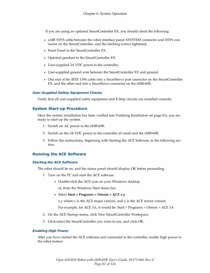
Chapter 6: System Operation
Viper 650/850 Robot with eMB-60R User’s Guide, 05173-060 Rev GPage 82 of 124
If you are using an optional SmartController EX, you should check the following:
l eAIB XSYS cable between the robot interface panel XSYSTEM connector and XSYS con-nector on the SmartController, and the latching screws tightened.
l Front Panel to the SmartController EX.
l Optional pendant to the SmartController EX.
l User-supplied 24 VDC power to the controller.
l User-supplied ground wire between the SmartController EX and ground.
l One end of the IEEE 1394 cable into a SmartServo port connector on the SmartControllerEX, and the other end into a SmartServo connector on the eMB-60R.
User-Supplied Safety Equipment Checks
Verify that all user-supplied safety equipment and E-Stop circuits are installed correctly.
System Start-up Procedure
Once the system installation has been verified (see Verifying Installation on page 81), you areready to start up the system.
1. Switch on AC power to the eMB-60R.
2. Switch on the 24 VDC power to the controller (if used) and the eMB-60R.
3. Follow the instructions, beginning with Starting the ACE Software, in the following sec-tion.
Running the ACE Software
Starting the ACE Software
The robot should be on, and the status panel should display OK before proceeding.
1. Turn on the PC and start the ACE software.
l Double-click the ACE icon on your Windows desktop
or, from the Windows Start menu bar,
l Select Start > Programs > Omron > ACE x.y
x.y where x is the ACE major version, and y is the ACE minor version.
For example, for ACE 3.6, it would be: Start > Programs > Omron > ACE 3.6
2. On the ACE Startup menu, click New SmartController Workspace.
3. Click-select the SmartController you want to use, and click OK.
Enabling High Power
After you have started the ACE software and connected to the controller, enable high power tothe robot motors:
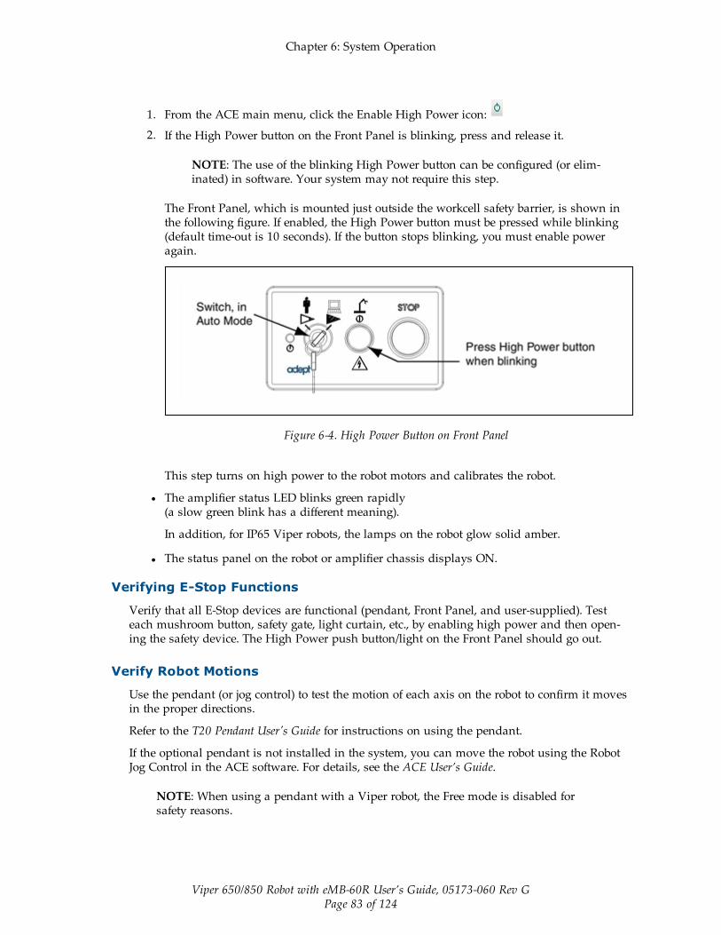
Chapter 6: System Operation
Viper 650/850 Robot with eMB-60R User’s Guide, 05173-060 Rev GPage 83 of 124
1. From the ACE main menu, click the Enable High Power icon:
2. If the High Power button on the Front Panel is blinking, press and release it.
NOTE: The use of the blinking High Power button can be configured (or elim-inated) in software. Your system may not require this step.
The Front Panel, which is mounted just outside the workcell safety barrier, is shown inthe following figure. If enabled, the High Power button must be pressed while blinking(default time-out is 10 seconds). If the button stops blinking, you must enable poweragain.
Figure 6-4. High Power Button on Front Panel
This step turns on high power to the robot motors and calibrates the robot.
l The amplifier status LED blinks green rapidly(a slow green blink has a different meaning).
In addition, for IP65 Viper robots, the lamps on the robot glow solid amber.
l The status panel on the robot or amplifier chassis displays ON.
Verifying E-Stop Functions
Verify that all E-Stop devices are functional (pendant, Front Panel, and user-supplied). Testeach mushroom button, safety gate, light curtain, etc., by enabling high power and then open-ing the safety device. The High Power push button/light on the Front Panel should go out.
Verify Robot Motions
Use the pendant (or jog control) to test the motion of each axis on the robot to confirm it movesin the proper directions.
Refer to the T20 Pendant User's Guide for instructions on using the pendant.
If the optional pendant is not installed in the system, you can move the robot using the RobotJog Control in the ACE software. For details, see the ACE User’s Guide.
NOTE: When using a pendant with a Viper robot, the Free mode is disabled forsafety reasons.

Chapter 6: System Operation
Viper 650/850 Robot with eMB-60R User’s Guide, 05173-060 Rev GPage 84 of 124
6.5 Learning to Program the RobotTo learn how to use and program the robot, see the ACE User’s Guide, which provides inform-ation on robot configuration, control and programming through the ACE software “point andclick” user interface.
For eV+ programming information, refer to the eV+ user and reference guides.
6.6 Installing Axis LabelsThe system includes a set of axis directional labels that can be installed on the robot. See thefollowing table. Also refer to Robot Axis Identification on page 7 for a drawing of the axis iden-tification. The yellow X-Y label can be used to indicate the X and Y axes in the World coordin-ate system in your workcell.
Table 6-1. Axis Directional Labels
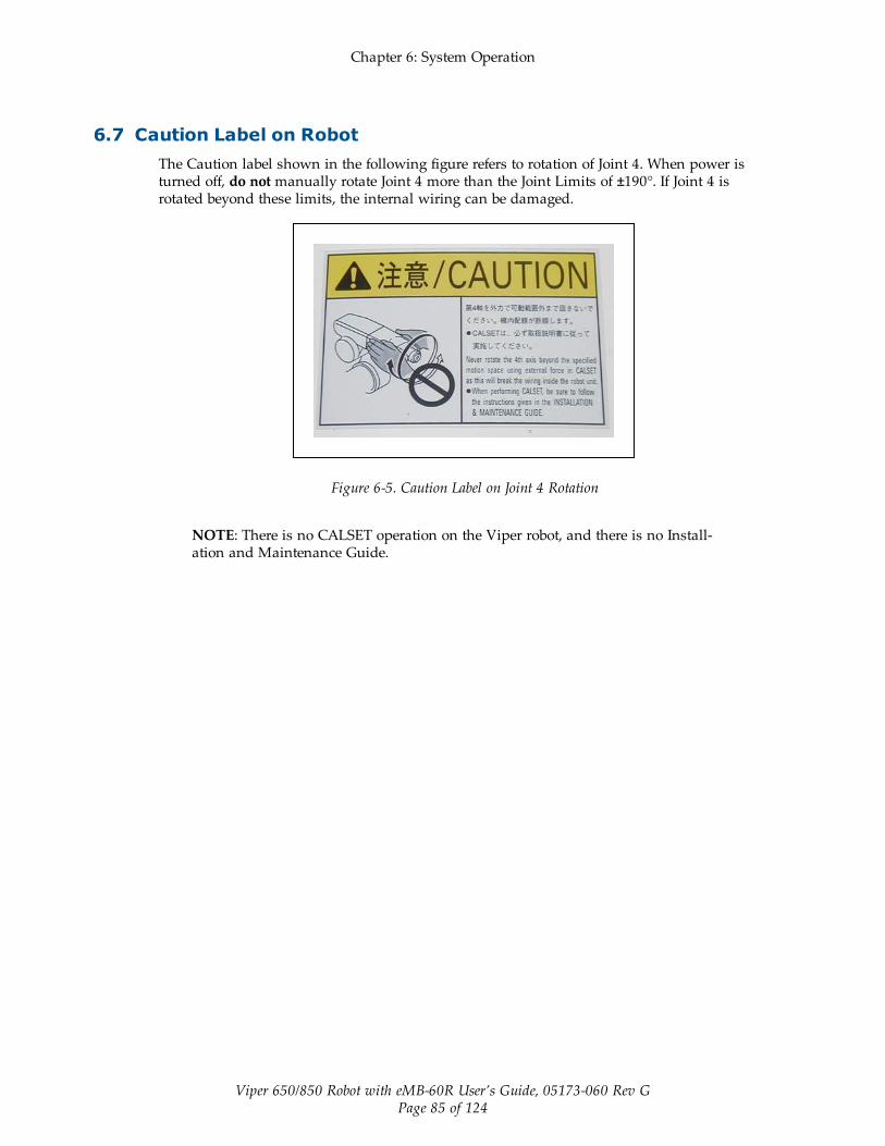
Chapter 6: System Operation
Viper 650/850 Robot with eMB-60R User’s Guide, 05173-060 Rev GPage 85 of 124
6.7 Caution Label on RobotThe Caution label shown in the following figure refers to rotation of Joint 4. When power isturned off, do not manually rotate Joint 4 more than the Joint Limits of ±190°. If Joint 4 isrotated beyond these limits, the internal wiring can be damaged.
Figure 6-5. Caution Label on Joint 4 Rotation
NOTE: There is no CALSET operation on the Viper robot, and there is no Install-ation and Maintenance Guide.


Viper 650/850 Robot with eMB-60R User’s Guide, 05173-060 Rev GPage 87 of 124
Chapter 7: Maintenance
7.1 Field-replaceable PartsWARNING: Only qualified service personnel may install orservice the robot system. All maintenance work must be per-formed by skilled and instructed personnel - refer to theRobot Safety Guide. The access covers on the robot are notinterlocked - turn off and disconnect power if covers have tobe removed.
WARNING: During maintenance, user-supplied fail-safelock-out measures must be used to prevent unauthorizedthird parties from turning on power.
This is mandated by Clause 5.2.4 of ISO 10218-1.
The only field-replaceable parts on the Viper 650/850 robots are the encoder battery and theeMB-60R.
The part number for the battery is 05234-000.
7.2 Periodic Maintenance ScheduleThe following table gives a summary of the preventive maintenance procedures andguidelines on frequency.
Also, for cleanroom robots, see Cleanroom Option on page 117. For IP54/65 robots, see IP54/65Option on page 113.
Item Period Reference
Check E-Stop, enable and key switches, andbarrier interlocks
6 months See Checking Safety Systemson page 88
Check robot mounting bolts 6 months See Checking Robot MountingBolts on page 88
Replace encoder battery 2 to 7 years See Replacing Encoder BackupBatteries on page 88
NOTE: The frequency of these procedures will depend on the particular system, itsoperating environment, and amount of usage. Use the times given here asguidelines and modify the schedule as needed.

Chapter 7: Maintenance
Viper 650/850 Robot with eMB-60R User’s Guide, 05173-060 Rev GPage 88 of 124
7.3 Checking Safety SystemsThese tests should be done every six months.
1. Test operation of:
l E-Stop button on Front Panel
l E-Stop button on pendant
l Enabling switch on pendant
l Auto/Manual switch on Front Panel
NOTE: Operating any of the above switches should disable high power.
2. Test operation of any external (user-supplied) E-Stop buttons.
3. Test operation of barrier interlocks, etc.
7.4 Checking Robot Mounting BoltsCheck the tightness of the base mounting bolts every 6 months. Tighten to 70 ± 14 N·m (52 ±10 ft-lbf).
7.5 Replacing Encoder Backup BatteriesCAUTION: Replace the batteries only with 3.6 V, 8.5 Ahlithium batteries, part number: 05234-000. Battery inform-ation is located in the base of the robot.
Battery Replacement Intervals
The encoder backup batteries should be replaced according to the intervals that follow.
l If the robot is kept in storage and not in production, or the robot is turned off (no 24VDC supply) most of the time, then the batteries should be replaced every two years.
l If the robot is turned on with 24 VDC supplied to the robot half the time, the batteriesshould be replaced every four years.
l If the robot is turned on with 24 VDC more than half the time, then you can increase thereplacement interval to seven years. If, for example, a robot is typically turned off onlyon weekends, the batteries would need to be replaced every seven years.
Battery Replacement Procedure
NOTE: Dispose of the batteries according to all local and national environmentalregulations regarding electronic components.
Replace the batteries according to the following procedure:
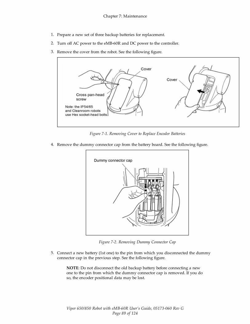
Chapter 7: Maintenance
Viper 650/850 Robot with eMB-60R User’s Guide, 05173-060 Rev GPage 89 of 124
1. Prepare a new set of three backup batteries for replacement.
2. Turn off AC power to the eMB-60R and DC power to the controller.
3. Remove the cover from the robot. See the following figure.
Figure 7-1. Removing Cover to Replace Encoder Batteries
4. Remove the dummy connector cap from the battery board. See the following figure.
Figure 7-2. Removing Dummy Connector Cap
5. Connect a new battery (1st one) to the pin from which you disconnected the dummyconnector cap in the previous step. See the following figure.
NOTE: Do not disconnect the old backup battery before connecting a newone to the pin from which the dummy connector cap is removed. If you doso, the encoder positional data may be lost.

Chapter 7: Maintenance
Viper 650/850 Robot with eMB-60R User’s Guide, 05173-060 Rev GPage 90 of 124
Figure 7-3. Connecting First New Battery
6. Disconnect the old backup battery that is next to the new battery connected in the pre-vious step, and then connect a new battery (2nd one). See the following figure.
NOTE: Be sure to replace all of three batteries with new ones at one time.Otherwise, the battery service life will be reduced.
Figure 7-4. Connecting Second New Battery
7. Disconnect the old backup battery that is next to the new battery connected in the pre-vioius step, and then connect a new battery (3rd one). See the following figure.
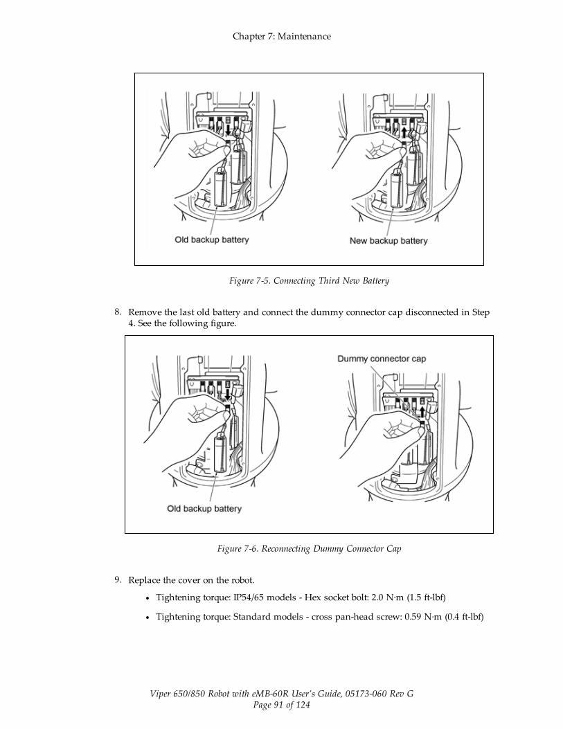
Chapter 7: Maintenance
Viper 650/850 Robot with eMB-60R User’s Guide, 05173-060 Rev GPage 91 of 124
Figure 7-5. Connecting Third New Battery
8. Remove the last old battery and connect the dummy connector cap disconnected in Step4. See the following figure.
Figure 7-6. Reconnecting Dummy Connector Cap
9. Replace the cover on the robot.
l Tightening torque: IP54/65 models - Hex socket bolt: 2.0 N·m (1.5 ft-lbf)
l Tightening torque: Standard models - cross pan-head screw: 0.59 N·m (0.4 ft-lbf)

Chapter 7: Maintenance
Viper 650/850 Robot with eMB-60R User’s Guide, 05173-060 Rev GPage 92 of 124
7.6 Replacing the eMB-60R Amplifier
Remove the eMB-60R Amplifier
1. Switch off the SmartController EX.
2. Switch off the 24 VDC and 200/240 VAC input supplies to the eMB-60R.
3. Disconnect the 24 VDC supply cable from the eMB-60R +24 VDC connector.
See Description of Connectors on eMB-60R Interface Panel on page 32 for locations ofconnectors.
4. Disconnect the 200/240 VAC supply cable from the eMB-60R AC connector.
5. Disconnect the eAIB XSYS cable from the eMB-60R XSYSTEM connector.
If the system was upgraded from an MB-60R to an eMB-60R, you may need to dis-connect the XSYS cable and eAIB XSLV Adapter from the XSYSTEM connector.
6. Disconnect the IEEE 1394 cable from the eMB-60R SmartServo connector.
7. Disconnect any other cables, which are connected to the eMB-60R, such as XIO.
Installing a New eMB-60R
1. Carefully remove the new eMB-60R from its packaging, check it for any signs of dam-age, and remove any foreign packing materials or debris.
2. Carefully place the eMB-60R next to the robot.
3. Connect the 200/240 VAC supply cable to the eMB-60R AC input connector.
4. Connect the eAIB XSYS cable to the eMB-60R XSYSTEM connector.
If you are upgrading from an MB-60R to an eMB-60R, connect the existing XSYS cableto the eAIB XSLV Adapter, which connects to the eMB-60R XSYSTEM connector.
5. Connect the IEEE 1394 cable to the eMB-60R SmartServo connector.
6. Connect any other cables, which were connected to the eMB-60R, such as XIO.
7. Connect the 24 VDC supply cable to the eMB-60R +24 VDC input connector.
8. Switch on the 200/240 VAC input supply to the eMB-60R.
9. Switch on the 24 VDC input supply to the eMB-60R.
10. Switch on the SmartController EX.
11. Once the system has completed booting:
l Verify that the new eMB-60R has been commissioned. The initial commissioningutility screen will tell you which functions are commissioned. Refer to Com-missioning Status on page 93.
l Test the system for proper operation.
7.7 Commissioning a System with an eMB-60RCommissioning a system involves synchronizing the robot with the eMB-60R.

Chapter 7: Maintenance
Viper 650/850 Robot with eMB-60R User’s Guide, 05173-060 Rev GPage 93 of 124
NOTE: This section only applies to robots that have an eMB-60R amplifier. A robotwith an MB-60R amplifier does not need the ACE commissioning.
For a new system with an eMB-60R, the robot and the eMB-60R will have been commissionedat the factory and should not need commissioning.
If you are replacing an MB-60R with an eMB-60R, you will need to commission the system.
In rare cases with a new robot with an eMB-60R, you may need to commission the system.
l If the system will not power up, and the robot status display shows SE, you need tocommission the system.
l If the system will not power up in Manual mode, and the robot status display showsTR, you need to commission the system.
Safety Commissioning Utilities
The eMB-60R adds two functions that implement safety in hardware:
l E-Stop serves as a backup to the standard software E-Stop process. The system willalways try to stop the robot using the software E-Stop first. The hardware E-Stop willtake over in the event of a failure of the software E-Stop.
l Teach Restrict limits the maximum speed of the robot when it is operated in Manualmode. As with the E-Stop, this is a hardware backup to software limits on robot speed.If the software fails to limit the robot speed during manual operation, the hardwareTeach Restrict will disable power to the system.
These two functions are only in the eMB-60R amplifiers. They were not implemented in hard-ware in the MB-60R amplifiers, so these utilities do not apply to those amplifiers.
These two functions are supported by four wizards:
l E-Stop Configuration
This sets the E-Stop hardware delay to factory specifications.
l E-Stop Verification
This verifies that the hardware E-Stop is functioning correctly.
l Teach Restrict Configuration
This sets the hardware Teach Restrict maximum speed to factory specifications.
l Teach Restrict Verification
This verifies that the hardware Teach Restrict is functioning correctly.
Commissioning Status
The initial utility screen will tell you which functions are commissioned. If a function is notcommissioned, its verification wizard will not be displayed. Any displayed verification wizardcan be run at any time, to ensure that its function is working properly.

Chapter 7: Maintenance
Viper 650/850 Robot with eMB-60R User’s Guide, 05173-060 Rev GPage 94 of 124
Prerequisites
l The robot must be set up and functional.
l The robot must use eMB-60R amplifiers.
The MB-60R amplifiers do not support these hardware functions, and these wizardswill not run.
l A PC with ACE software version 3.3.2.10 or later must be connected to the eMB-60R.
l The Front Panel keyswitch must be in Auto mode.
Figure 7-7. Front Panel
l A manual control pendant is required for the Teach Restrict verification.
l No E-Stops can be activated.
l For Configuration (E-Stop and Teach Restrict), the eAIB Commissioning Jumper must beplugged into the XBELTIO jack on the eMB-60R.
NOTE: This is the only time that this jumper will be used. It is part number11901-000, and must be removed for Verification and normal operation.
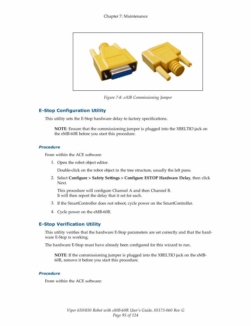
Chapter 7: Maintenance
Viper 650/850 Robot with eMB-60R User’s Guide, 05173-060 Rev GPage 95 of 124
Figure 7-8. eAIB Commissioning Jumper
E-Stop Configuration Utility
This utility sets the E-Stop hardware delay to factory specifications.
NOTE: Ensure that the commissioning jumper is plugged into the XBELTIO jack onthe eMB-60R before you start this procedure.
Procedure
From within the ACE software:
1. Open the robot object editor.
Double-click on the robot object in the tree structure, usually the left pane.
2. Select Configure > Safety Settings > Configure ESTOP Hardware Delay, then clickNext.
This procedure will configure Channel A and then Channel B.It will then report the delay that it set for each.
3. If the SmartController does not reboot, cycle power on the SmartController.
4. Cycle power on the eMB-60R.
E-Stop Verification Utility
This utility verifies that the hardware E-Stop parameters are set correctly and that the hard-ware E-Stop is working.
The hardware E-Stop must have already been configured for this wizard to run.
NOTE: If the commissioning jumper is plugged into the XBELTIO jack on the eMB-60R, remove it before you start this procedure.
Procedure
From within the ACE software:

Chapter 7: Maintenance
Viper 650/850 Robot with eMB-60R User’s Guide, 05173-060 Rev GPage 96 of 124
1. Open the robot object editor.
Double-click on the robot object in the tree structure, usually the left pane.
2. Select Configure > Safety Settings > Verify ESTOP Hardware Delay, then click Next.
3. Enable high power, if not already enabled, then click Next.
4. Press an E-Stop button (on the Front Panel), then click Next.
The utility will confirm that the hardware delay has been verified for this robot, and dis-play the delay times for channels A and B.
5. If the SmartController does not reboot, cycle power on the SmartController.
Teach Restrict Configuration Utility
This utility sets the hardware Teach Restrict maximum speed parameter to factory spe-cifications.
NOTE: Ensure that the commissioning jumper is plugged into the XBELTIO jack onthe eMB-60R before you start this procedure.
Procedure
NOTE: This procedure takes 2 or 3 minutes to complete.
From within the ACE software:
1. Open the robot object editor.
Double-click on the robot object in the tree structure, usually the left pane.
2. Select Configure > Safety Settings > Configure Teach Restrict, then click Next.
3. From the Prerequisite screen, click Next.
The wizard will go through all of the robot's motors, and display messages that it is con-figuring Channel A and B for each.
It will then record the configuration, and display the target times that it set.
4. Click Finish.
5. If the SmartController does not reboot, cycle power on the SmartController.
Teach Restrict Verification Utility
This utility verifies that the Teach Restrict parameters are set correctly and that the hardwareTeach Restrict maximum speed control is working.
This is a two-part wizard. The first is run in Auto mode. The second is run in Manual mode.
Before running this verification utility, the Teach Restrict must be configured.
NOTE: If the commissioning jumper is plugged into the XBELTIO jack on the eMB-60R, remove it before you start this procedure.

Chapter 7: Maintenance
Viper 650/850 Robot with eMB-60R User’s Guide, 05173-060 Rev GPage 97 of 124
Automatic Mode Procedure
WARNING: The robot will move during this wizard.Ensure that personnel stay clear of the robot work area.
From within the ACE software:
1. Open the robot object editor.
Double-click on the robot object in the tree structure, usually the left pane.
2. Select Configure > Safety Settings > Verify Teach Restrict, then click Next.
3. Teach a Start Position.
NOTE: This procedure will move the robot approximately ±5 degrees fromthe starting point of each joint.
This can be any position that does not conflict with obstacles or the limits of joint move-ments.
l If the robot is already in such a position, you can just click Next.
l Otherwise, move the robot to such a position, then click Next.
l The screen will display the number of degrees that each joint is expected to moveduring the verification process.
l You can click Preview Motions on this screen to view the motions at slow speed.The default speed is 10, but you can change that speed with this screen's speedcontrol.
l You can click Move to Ready, to move the robot to the Ready position.
The robot will move each joint, in succession. It will generate an over-speed con-dition for each, and verify that the hardware detected the over-speed condition.
4. Click Next, to proceed to the Manual Mode Procedure.
If the Automatic Mode Procedure fails, you will not be allowed to proceed with theManual Mode.
Manual Mode Procedure
The manual mode of this verification requires the use of a manual control pendant.
For this verification, the Front Panel keyswitch must be in Manual mode.
1. From the Introduction screen, click Next.
l Set the pendant to Joint mode.
l Set the pendant manual control speed to 100.
2. Click Next.
3. Using the pendant, jog any of the robot's joints until power is disabled.

Chapter 7: Maintenance
Viper 650/850 Robot with eMB-60R User’s Guide, 05173-060 Rev GPage 98 of 124
This indicates that the Teach Restrict function is working.
4. Click Next.
The results of the verification will be displayed.
5. Click Finish.
6. If the SmartController does not reboot, cycle power on the SmartController.
7. Reset the Front Panel keyswitch to Auto mode.
7.8 Changing the Lamp in the Front Panel High-Power IndicatorThe system is equipped with circuitry to detect the potentially dangerous condition of aburned-out High Power indicator on the Front Panel. If this lamp is burned out, you cannotenable high power until the lamp has been replaced. Follow this procedure to replace the HighPower indicator lamp. The part number for the lamp is 27400-29006.
WARNING: Lockout and tagout power before servicing.
WARNING: The procedures and replacement of parts mentioned inthis section should be performed only by trained, authorized per-sonnel. The access covers on the Front Panel are not interlocked –turn off and disconnect power before removing the cover.
1. Turn off system power to the robot.
2. Turn off power to the optional SmartController EX, if you are using one.
3. Disconnect the cable between the Front Panel and the eAIB (or controller).
4. Remove the Front Panel from its mounting location.
5. Remove the two screws on the back of the Front Panel.
Save the screws for re-installation.
6. Carefully pull the front cover away from the body of the Front Panel.
You will encounter some resistance, as there are three plug-type connectors that youneed to disconnect as you pull the front cover away from the body.
NOTE: Separate the cover from the body slowly to avoid damaging the twowires that go between the LED and the PC board inside the body. Pull thefront cover as straight out as possible. You do not have to disconnect thewires from the PC board, although you can if needed.
7. Locate the lamp body in the center of the back side of the front cover. Turn the lampbody approximately 20° in either direction and then pull straight back.
8. The lamp body is now free. You can remove the old lamp and insert a new one.
9. Re-install the lamp body by pushing it straight into the lamp housing receptacle. Make

Chapter 7: Maintenance
Viper 650/850 Robot with eMB-60R User’s Guide, 05173-060 Rev GPage 99 of 124
sure the contacts on the lamp body are properly oriented, as shown in the following fig-ure.
10. Make sure to reconnect the wires from the LED if you disconnected them earlier.
11. Push the front cover into the body, taking care to align all of the plug-type connectors.
Verify that the wires do not get crimped as you reinstall the cover.
12. Re-install the two screws on the back of the body.
13. Re-install the Front Panel in its mounting.
14. Reconnect the cable between the Front Panel and the eAIB (or controller).
High Power On/Off
Lamp Body
Back side of front cover
Wires between LED and
body of Front Panel.
Be careful when separating
front cover from body to avoid
damaging the wires.
Figure 7-9. Lamp Body Contact Alignment

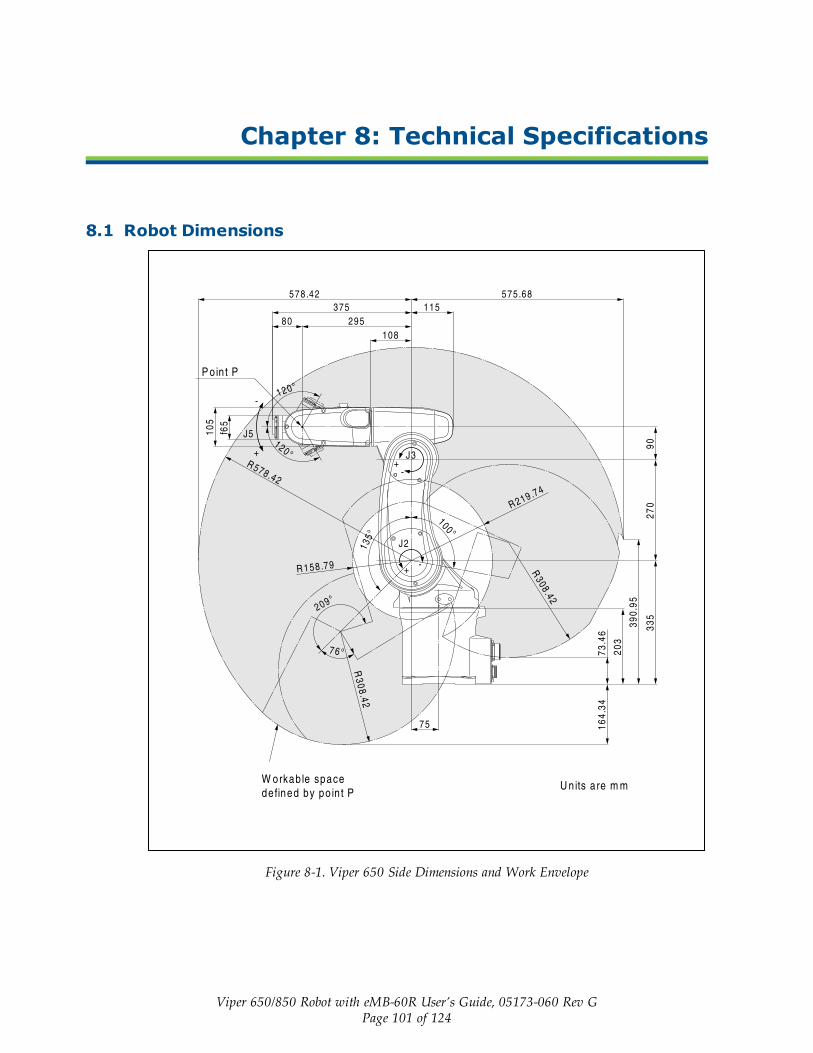
Viper 650/850 Robot with eMB-60R User’s Guide, 05173-060 Rev GPage 101 of 124
Chapter 8: Technical Specifications
8.1 Robot Dimensions
Figure 8-1. Viper 650 Side Dimensions and Work Envelope
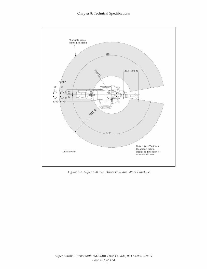
Chapter 8: Technical Specifications
Viper 650/850 Robot with eMB-60R User’s Guide, 05173-060 Rev GPage 102 of 124
Figure 8-2. Viper 650 Top Dimensions and Work Envelope

Chapter 8: Technical Specifications
Viper 650/850 Robot with eMB-60R User’s Guide, 05173-060 Rev GPage 103 of 124
Figure 8-3. Viper 850 Side Dimensions and Work Envelope
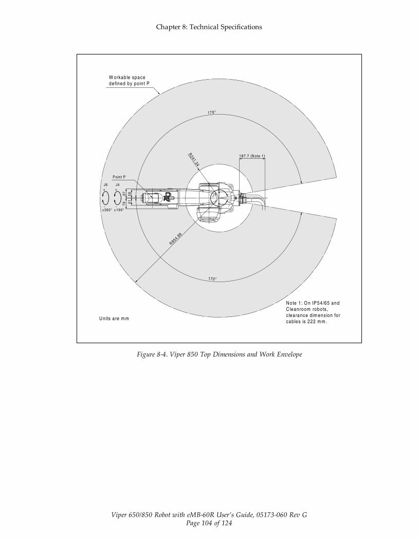
Chapter 8: Technical Specifications
Viper 650/850 Robot with eMB-60R User’s Guide, 05173-060 Rev GPage 104 of 124
Figure 8-4. Viper 850 Top Dimensions and Work Envelope
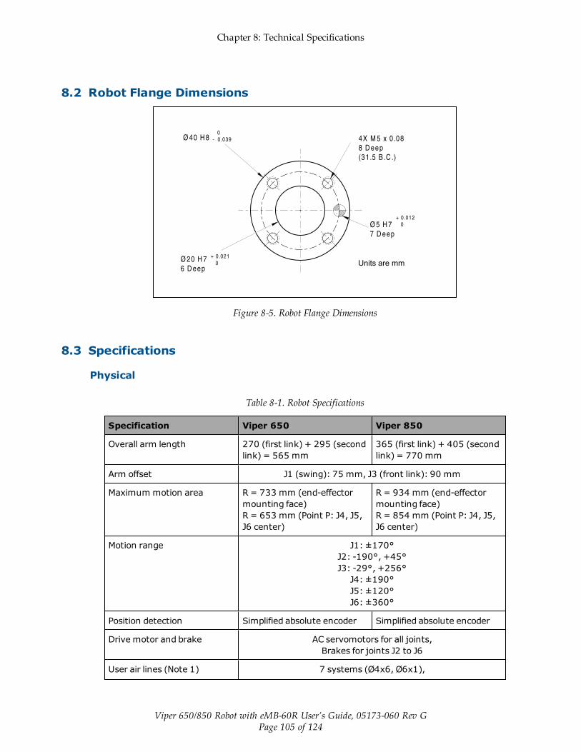
Chapter 8: Technical Specifications
Viper 650/850 Robot with eMB-60R User’s Guide, 05173-060 Rev GPage 105 of 124
8.2 Robot Flange Dimensions
Figure 8-5. Robot Flange Dimensions
8.3 Specifications
Physical
Table 8-1. Robot Specifications
Specification Viper 650 Viper 850
Overall arm length 270 (first link) + 295 (secondlink) = 565 mm
365 (first link) + 405 (secondlink) = 770 mm
Arm offset J1 (swing): 75 mm, J3 (front link): 90 mm
Maximum motion area R = 733 mm (end-effectormounting face)R = 653 mm (Point P: J4, J5,J6 center)
R = 934 mm (end-effectormounting face)R = 854 mm (Point P: J4, J5,J6 center)
Motion range J1: ±170°J2: -190°, +45°J3: -29°, +256°J4: ±190°J5: ±120°J6: ±360°
Position detection Simplified absolute encoder Simplified absolute encoder
Drive motor and brake AC servomotors for all joints,Brakes for joints J2 to J6
User air lines (Note 1) 7 systems (Ø4x6, Ø6x1),

Chapter 8: Technical Specifications
Viper 650/850 Robot with eMB-60R User’s Guide, 05173-060 Rev GPage 106 of 124
Specification Viper 650 Viper 850
3 solenoid valves (2-position, double solenoid) contained.
User signal line 10 (for proximity sensor signals, etc.)
Air source - Operating pres-sure
0.1 to 3.9 MPa(14.5 to 56.6 psi)
Air source - Maximum allow-able pressure
0.49 MPa (71.1 psi)
Degree of Protection IP40 (IP54/65 w/ option) IP40 (IP54/65 w/ option)
Weight Approx. 28 kg Approx. 29 kg
Note 1: Only the Ø4x6 air tubing system may be controlled by built-in solenoid valves.
Performance
Specification Viper 650 Viper 850
Maximum joint speed J1: 328°/secJ2: 300°/secJ3: 375°/secJ4: 375°/secJ5: 375°/secJ6: 600°/sec
J1: 250°/secJ2: 250°/secJ3: 250°/secJ4: 375°/secJ5: 375°/secJ6: 600°/sec
Maximum composite speed(at the center of an end-effector mounting face)
8200 mm/s 7600 mm/s
Maximum payload 5 kg
Position repeatability (Note 2) In each of X, Y and Z dir-ections: ±0.02 mm
In each of X, Y and Z dir-ections: ±0.03 mm
Maximum allowable inertiamoment
Around J4: 0.295 kgm2
Around J5: 0.295 kgm2
Around J6: 0.045 kgm2
Note 2: Position repeatability is the value at constant ambient temperature.

Chapter 8: Technical Specifications
Viper 650/850 Robot with eMB-60R User’s Guide, 05173-060 Rev GPage 107 of 124
Stopping Distances and Times
0
10
20
30
40
50
60
70
80
0 20 40 60 80 100 120
Stop
ping
Dis
tanc
e (d
eg)
Speed (%)
J1 Stopping Distance (Viper650)
Payload 33%
Payload 66%
Payload 100%
Figure 8-6. Joint 1 Stopping Distance for Viper 650, in Degrees
0
0.1
0.2
0.3
0.4
0.5
0 20 40 60 80 100 120
Stop
ping
Tim
e (s
)
Speed (%)
J1 Stopping Time (Viper650)
Payload 33%
Payload 66%
Payload 100%
Figure 8-7. Joint 1 Stopping Time for Viper 650, in Seconds

Chapter 8: Technical Specifications
Viper 650/850 Robot with eMB-60R User’s Guide, 05173-060 Rev GPage 108 of 124
0
10
20
30
40
50
60
70
80
0 20 40 60 80 100 120
Stop
ping
Dis
tanc
e (d
eg)
Speed (%)
J2 Stopping Distance (Viper650)
Payload 33%
Payload 66%
Payload 100%
Figure 8-8. Joint 2 Stopping Distance for Viper 650, in Degrees
0
0.1
0.2
0.3
0.4
0.5
0 20 40 60 80 100 120
Stop
ping
Tim
e (s
)
Speed (%)
J2 Stopping Time (Viper650)
Payload 33%
Payload 66%
Payload 100%
Figure 8-9. Joint 2 Stopping Time for Viper 650, in Seconds
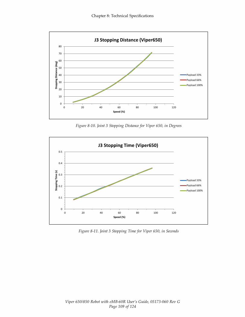
Chapter 8: Technical Specifications
Viper 650/850 Robot with eMB-60R User’s Guide, 05173-060 Rev GPage 109 of 124
0
10
20
30
40
50
60
70
80
0 20 40 60 80 100 120
Stop
ping
Dis
tanc
e (d
eg)
Speed (%)
J3 Stopping Distance (Viper650)
Payload 33%
Payload 66%
Payload 100%
Figure 8-10. Joint 3 Stopping Distance for Viper 650, in Degrees
0
0.1
0.2
0.3
0.4
0.5
0 20 40 60 80 100 120
Stop
ping
Tim
e (s
)
Speed (%)
J3 Stopping Time (Viper650)
Payload 33%
Payload 66%
Payload 100%
Figure 8-11. Joint 3 Stopping Time for Viper 650, in Seconds
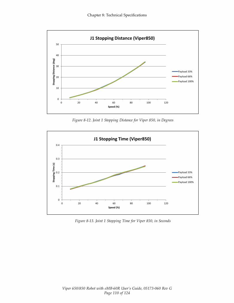
Chapter 8: Technical Specifications
Viper 650/850 Robot with eMB-60R User’s Guide, 05173-060 Rev GPage 110 of 124
0
10
20
30
40
50
0 20 40 60 80 100 120
Stop
ping
Dis
tanc
e (d
eg)
Speed (%)
J1 Stopping Distance (Viper850)
Payload 33%
Payload 66%
Payload 100%
Figure 8-12. Joint 1 Stopping Distance for Viper 850, in Degrees
0
0.1
0.2
0.3
0.4
0 20 40 60 80 100 120
Stop
ping
Tim
e (s
)
Speed (%)
J1 Stopping Time (Viper850)
Payload 33%
Payload 66%
Payload 100%
Figure 8-13. Joint 1 Stopping Time for Viper 850, in Seconds

Chapter 8: Technical Specifications
Viper 650/850 Robot with eMB-60R User’s Guide, 05173-060 Rev GPage 111 of 124
0
10
20
30
40
50
0 20 40 60 80 100 120
Stop
ping
Dis
tanc
e (d
eg)
Speed (%)
J2 Stopping Distance (Viper850)
Payload 33%
Payload 66%
Payload 100%
Figure 8-14. Joint 2 Stopping Distance for Viper 850, in Degrees
0
0.1
0.2
0.3
0.4
0 20 40 60 80 100 120
Stop
ping
Tim
e (s
)
Speed (%)
J2 Stopping Time (Viper850)
Payload 33%
Payload 66%
Payload 100%
Figure 8-15. Joint 2 Stopping Time for Viper 850, in Seconds

Chapter 8: Technical Specifications
Viper 650/850 Robot with eMB-60R User’s Guide, 05173-060 Rev GPage 112 of 124
0
10
20
30
40
50
0 20 40 60 80 100 120
Stop
ping
Dis
tanc
e (d
eg)
Speed (%)
J3 Stopping Distance (Viper850)
Payload 33%
Payload 66%
Payload 100%
Figure 8-16. Joint 3 Stopping Distance for Viper 850, in Degrees
0
0.1
0.2
0.3
0.4
0 20 40 60 80 100 120
Stop
ping
Tim
e (s
)
Speed (%)
J3 Stopping Time (Viper850)
Payload 33%
Payload 66%
Payload 100%
Figure 8-17. Joint 3 Stopping Time for Viper 850, in Seconds

Viper 650/850 Robot with eMB-60R User’s Guide, 05173-060 Rev GPage 113 of 124
Chapter 9: IP54/65 Option
9.1 IntroductionThe Viper 650 and 850 robots can be ordered with an IP54/65 option that is a dust-proof,splash-proof model. With the IP54/65 option, the main body of the robot is rated IP54, andJoints 4, 5, 6 are rated IP65. Without this option, the robots have a rating of IP40.
CAUTION: The SmartController and eMB-60R are not dust-or splash-proof. Therefore, when using these products in anenvironment exposed to dust or mist, put them in protectiveenclosures.
Figure 9-1. Viper 650 Robot with IP54/65 Option

Chapter 9: IP54/65 Option
Viper 650/850 Robot with eMB-60R User’s Guide, 05173-060 Rev GPage 114 of 124
9.2 Differences from the Standard Robot ModelThe installation, operation, and specifications of the IP54/65 robot are the same as the standardrobot, except for issues noted in this section.
Installation Environment
The IP54/65 robot should not be installed in any environment where:
l there are any flammable gases or liquids,
l there are any acidic, alkaline, or other corrosive gases,
l there are any large-sized inverters, high output/high frequency transmitters, large con-tactors, welders, or other sources of electrical noise,
l it may likely be submerged in fluid,
l there is sulfuric cutting or grinding oil mist.
NOTE: Any machining oil used around the robot must be compatible with NBR(nitrile) and a polyurethane resin paint.
Robot Connector Panel
For the IP54/65 robot, the robot connector panel is different than the standard robot. The panelis shown in the following figure.
Figure 9-2. IP54/65 Robot Connector Panel
NOTE: On the IP54/65 robot, the CN20 and CN21 connectors are IP65 rated. Also,the robot cable has a splash-proof connector on the robot end.
NOTE: The mating connector sets for CN20 and CN21 are different for IP54/65 andCleanroom robots. See Cleanroom Option on page 117.

Chapter 9: IP54/65 Option
Viper 650/850 Robot with eMB-60R User’s Guide, 05173-060 Rev GPage 115 of 124
NOTE: For IP54/65 compliance, keep the factory-installed plugs over I/O connectorsin place.
Cable Clearance
For the IP54/65 robot, the cable clearance dimension at the back of the robot is 222 mm. SeeTechnical Specifications on page 101 for dimension drawings.
Replacing Encoder Backup Battery
For the IP54/65 robot, the procedure to replace the encoder battery is the same as the standardrobot, except the cover uses hex socket-head bolts instead of screws. Removing Cover toReplace Encoder Batteries on page 89. Tightening torque: Hex socket bolt: 2.0 N·m (1.5 ft-lbf).


Viper 650/850 Robot with eMB-60R User’s Guide, 05173-060 Rev GPage 117 of 124
Chapter 10: Cleanroom Option
10.1 IntroductionThe Viper 650 and 850 robots are available in Class 10 Cleanroom models.
Figure 10-1. Viper 850 Robot - Cleanroom Model
10.2 Differences from Standard Robot ModelThe installation, operation, and specifications of the Cleanroom robot are the same as thestandard robot, except for issues noted in this section.
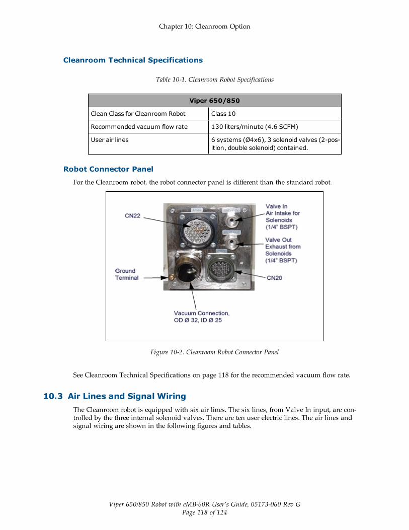
Chapter 10: Cleanroom Option
Viper 650/850 Robot with eMB-60R User’s Guide, 05173-060 Rev GPage 118 of 124
Cleanroom Technical Specifications
Table 10-1. Cleanroom Robot Specifications
Viper 650/850
Clean Class for Cleanroom Robot Class 10
Recommended vacuum flow rate 130 liters/minute (4.6 SCFM)
User air lines 6 systems (Ø4x6), 3 solenoid valves (2-pos-ition, double solenoid) contained.
Robot Connector Panel
For the Cleanroom robot, the robot connector panel is different than the standard robot.
Figure 10-2. Cleanroom Robot Connector Panel
See Cleanroom Technical Specifications on page 118 for the recommended vacuum flow rate.
10.3 Air Lines and Signal WiringThe Cleanroom robot is equipped with six air lines. The six lines, from Valve In input, are con-trolled by the three internal solenoid valves. There are ten user electric lines. The air lines andsignal wiring are shown in the following figures and tables.

Chapter 10: Cleanroom Option
Viper 650/850 Robot with eMB-60R User’s Guide, 05173-060 Rev GPage 119 of 124
Table 10-2. Air Intake/Exhaust States
Air Con-nections
Valve Signal
Intak-e
(Valv-e in)
Exhau-st
(Valveout)
Solen-oidValve
Solenoid
A B
1A 1B 1 ON OF-F
1B 1A 1 OF-F
ON
2A 2B 2 ON OF-F
2B 2A 2 OF-F
ON
3A 3B 3 ON OF-F
3B 3A 3 OF-F
ON
AIR 2 - Not used on Cleanroomrobot
Table 10-3. CN 20 Pin Assignments, M to U
NPN type (source IN,sink OUT)
PNP type (sink IN, sourceOUT)
CN20pin Used for:
CN20pin Used for:
M +24 V M 0 V
N Solenoid 1A(solenoid valve1)
N Solenoid 1A(solenoid valve 1)
P Solenoid 1B(solenoid valve1)
P Solenoid 1B(solenoid valve 1)

Chapter 10: Cleanroom Option
Viper 650/850 Robot with eMB-60R User’s Guide, 05173-060 Rev GPage 120 of 124
R Solenoid 2A(solenoid valve2)
R Solenoid 2A(solenoid valve 2)
S Solenoid 2B(solenoid valve2)
S Solenoid 2B(solenoid valve 2)
T Solenoid 3A(solenoid valve3)
T Solenoid 3A(solenoid valve 3)
U Solenoid 3B(solenoid valve3)
U Solenoid 3B(solenoid valve 3)
Pins A to K on CN20 and#1 to #10 on CN21 are connected with each other as shown below.The allowable current per line is 1 A.
CN20 A B C D E F G H J K
CN21 1 2 3 4 5 6 7 8 9 10
Use the supplied mating connector sets shown in the table below for CN20 and CN21.
CN20 and CN21 Mating Connectors
Table 10-4. CN20 and CN21 Mating Connectors
ConnectorSet
Part No.
ConnectorNo. Model and Part Name Appearance
Connector SetPart No.
05584-000 for CN20 H/M3106A22-14S (straightplug)(HIROSE ELECTRIC CO., LTD.)
for CN20 H/MS3057-12A (cord clamp)(HIROSE ELECTRIC CO., LTD.)
Applicable wirediameter11.4 to 15.9
for CN20 H/MS3057-12A1 (cord clamp)(HIROSE ELECTRIC CO., LTD.)
Applicable wirediameter 8 to11.6
for CN21 EBLP1610M (L type plug con-nector)(Dai-ichi Electronic Industry)
NOTE: The mating connectors are the same for Cleanroom and IP54/65 robots.

Chapter 10: Cleanroom Option
Viper 650/850 Robot with eMB-60R User’s Guide, 05173-060 Rev GPage 121 of 124
10.4 Cleanroom Cover at J6 FlangeThe Cleanroom robot has a J6 Cleanroom Cover that is not present on the standard robot. Seethe following figure. Any user tooling at the flange must allow for clearance - see See "J6 Clean-room Cover Dimensions".
Figure 10-3. Viper 850 J6 Cleanroom Cover
Figure 10-4. J6 Cleanroom Cover Dimensions
10.5 Cable ClearanceFor the Cleanroom robot, the cable clearance dimension at the back of the robot is 222 mm.Technical Specifications on page 101 for dimension drawings.

Chapter 10: Cleanroom Option
Viper 650/850 Robot with eMB-60R User’s Guide, 05173-060 Rev GPage 122 of 124
10.6 Replacing Encoder Backup BatteryFor the Cleanroom robot, the procedure to replace the encoder battery is the same as the stand-ard robot, except the cover uses hex socket-head bolts instead of screws. See See "RemovingCover to Replace Encoder Batteries". Tightening torque: Hex socket bolt: 2.0 N·m (1.5 ft-lbf).


Authorized Distributor:
In the interest of product improvement, specifications are subject to change without notice.
Cat. No. I599-E-01
Printed in USA
0416
© OMRON Corporation 2016 All Rights Reserved.
OMRON Corporation Industrial Automation Company
OMRON ELECTRONICS LLC2895 Greenspoint Parkway, Suite 200 Hoffman Estates, IL 60169 U.S.A.Tel: (1) 847-843-7900/Fax: (1) 847-843-7787
OMRON ADEPT TECHNOLOGIES, INC. 4550 Norris Canyon Road, Suite 150, San Ramon, CA 94583 U.S.A.Tel: (1) 925-245-3400/Fax: (1) 925-960-0590
Regional HeadquartersOMRON EUROPE B.V.Wegalaan 67-69, 2132 JD HoofddorpThe NetherlandsTel: (31)2356-81-300/Fax: (31)2356-81-388
Contact: www.ia.omron.comKyoto, JAPAN
OMRON ASIA PACIFIC PTE. LTD.No. 438A Alexandra Road # 05-05/08 (Lobby 2), Alexandra Technopark, Singapore 119967Tel: (65) 6835-3011/Fax: (65) 6835-2711 OMRON (CHINA) CO., LTD.
Room 2211, Bank of China Tower, 200 Yin Cheng Zhong Road, PuDong New Area, Shanghai, 200120, ChinaTel: (86) 21-5037-2222/Fax: (86) 21-5037-2200