VIPA System 300S · 4 Analog Output Modules ... AO 4x12Bit U for manual operation..... 109 VIPA...
165
SM-AIO | | Manual HB140 | SM-AIO | | GB | Rev. 16-39 VIPA System 300S Analog signal modules - SM 33x(S)
-
Upload
nguyendien -
Category
Documents
-
view
245 -
download
1
Transcript of VIPA System 300S · 4 Analog Output Modules ... AO 4x12Bit U for manual operation..... 109 VIPA...
SM-AIO | | ManualHB140 | SM-AIO | | GB | Rev. 16-39
VIPA System 300S
Analog signal modules - SM 33x(S)

300S_SM-AIO,4,GB - © 2016
VIPA GmbHOhmstr. 491074 HerzogenaurachTelephone: 09132-744-0Fax: 09132-744-1864Email: [email protected]: www.vipa.com
Table of contents1 Basics....................................................................................... 5
1.1 Copyright © VIPA GmbH ................................................... 51.2 Über dieses Handbuch....................................................... 61.3 Safety information.............................................................. 7
2 Assembly and installation guidelines.................................... 92.1 Safety information for users............................................... 92.2 Overview............................................................................ 92.3 Installation dimensions..................................................... 102.4 Assembly SPEED-Bus..................................................... 122.5 Assembly standard bus.................................................... 152.6 Cabling............................................................................. 172.7 Installation guidelines....................................................... 202.8 General data I/O modules................................................ 232.8.1 General data................................................................. 23
3 Analog Input Modules............................................................ 263.1 Principles.......................................................................... 263.2 Parameterization - Basics................................................ 273.2.1 Parameterization by hardware configuration................. 273.2.2 Parameterization during runtime................................... 273.3 331-1KF01 - AI 8x13Bit ................................................... 303.3.1 331-1KF01 - AI 8x13Bit - Parameterization.................. 343.3.2 331-1KF01 - Technical data.......................................... 403.4 331-7Kx01 - AI 8(2)x12Bit ............................................... 453.4.1 Connection of sensors ................................................. 483.4.2 331-7Kx01 - AI 8(2)x12Bit - Parameterization.............. 533.4.3 331-7Kx01 - AI 8(2)x12Bit - Diagnostics....................... 613.4.4 331-7KB01 - Technical data.......................................... 663.4.5 331-7KF01 - Technical data.......................................... 73
4 Analog Output Modules......................................................... 804.1 General............................................................................ 804.2 Connecting loads and actuators....................................... 804.3 Analog value representation............................................ 824.4 Parameterization - Basics................................................ 824.4.1 Parameterization by hardware configuration................. 824.4.2 Parameterization during run time by means of SFCs... 834.5 Diagnostics ...................................................................... 864.6 332-5HB01 - AO 2/4x12Bit U/I 2-channel........................ 904.6.1 Technical data............................................................... 934.7 332-5HD01 - AO 2/4x12Bit U/I 4-channel........................ 964.7.1 Technical data............................................................... 994.8 332-5HD50 - AO 4x12Bit I for manual operation........... 1024.8.1 Manual operation........................................................ 1054.8.2 Technical data............................................................. 1064.9 332-5HD60 - AO 4x12Bit U for manual operation.......... 109
VIPA System 300S Table of contents
HB140 | SM-AIO | | GB | Rev. 16-39 3

4.9.1 Manual operation......................................................... 1114.9.2 Technical data.............................................................. 112
5 Analog I/O Modules.............................................................. 1155.1 General........................................................................... 1155.2 Analog value representation........................................... 1155.3 Parameterization............................................................ 1185.3.1 Parameterization by hardware configuration............... 1185.3.2 Parameterization during run time by means of SFCs.. 1195.4 334-0KE00 - AI 4/AO 2x12Bit ....................................... 1205.4.1 Technical data............................................................. 121
6 Analog I/O Modules FAST - SPEED-Bus............................ 1286.1 General.......................................................................... 1286.2 Analog value representation.......................................... 1296.3 Operating modes............................................................ 1306.4 Addressing at SPEED-Bus............................................. 1316.5 Project engineering........................................................ 1326.5.1 Fast introduction.......................................................... 1326.5.2 Preconditions.............................................................. 1326.5.3 Steps of project engineering....................................... 1336.6 Parameterization............................................................ 1356.6.1 Structure of the parameter bytes................................. 1366.7 SFC 193 - Oscilloscope-/FIFO function ........................ 1406.8 Example for the Oscilloscope function........................... 1446.8.1 Example for the FIFO function.................................... 1466.9 Diagnostics..................................................................... 1506.9.1 Process interrupts....................................................... 1526.10 331-7AF70 - AI 8x16Bit I ............................................. 1536.10.1 Technical data........................................................... 1566.11 331-7BF70 - AI 8x16Bit U............................................. 1596.11.1 Technical data............................................................ 161
VIPA System 300STable of contents
HB140 | SM-AIO | | GB | Rev. 16-39 4

1 Basics1.1 Copyright © VIPA GmbH
This document contains proprietary information of VIPA and is not tobe disclosed or used except in accordance with applicable agree-ments.This material is protected by the copyright laws. It may not be repro-duced, distributed, or altered in any fashion by any entity (eitherinternal or external to VIPA), except in accordance with applicableagreements, contracts or licensing, without the express written con-sent of VIPA and the business management owner of the material.For permission to reproduce or distribute, please contact: VIPA,Gesellschaft für Visualisierung und Prozessautomatisierung mbHOhmstraße 4, D-91074 Herzogenaurach, GermanyTel.: +49 9132 744 -0Fax.: +49 9132 744-1864EMail: [email protected]://www.vipa.com
Every effort has been made to ensure that the informa-tion contained in this document was complete andaccurate at the time of publishing. Nevertheless, theauthors retain the right to modify the information.This customer document describes all the hardwareunits and functions known at the present time. Descrip-tions may be included for units which are not present atthe customer site. The exact scope of delivery isdescribed in the respective purchase contract.
Hereby, VIPA GmbH declares that the products and systems are incompliance with the essential requirements and other relevant provi-sions. Conformity is indicated by the CE marking affixed to theproduct.
For more information regarding CE marking and Declaration of Con-formity (DoC), please contact your local VIPA customer serviceorganization.
All Rights Reserved
CE Conformity Declara-tion
Conformity Information
VIPA System 300S BasicsCopyright © VIPA GmbH
HB140 | SM-AIO | | GB | Rev. 16-39 5
VIPA, SLIO, System 100V, System 200V, System 300V, System300S, System 400V, System 500S and Commander Compact areregistered trademarks of VIPA Gesellschaft für Visualisierung undProzessautomatisierung mbH.SPEED7 is a registered trademark of profichip GmbH.SIMATIC, STEP, SINEC, TIA Portal, S7-300 and S7-400 are regis-tered trademarks of Siemens AG.Microsoft and Windows are registered trademarks of Microsoft Inc.,USA.Portable Document Format (PDF) and Postscript are registered trade-marks of Adobe Systems, Inc.All other trademarks, logos and service or product marks specifiedherein are owned by their respective companies.
Contact your local VIPA Customer Service Organization representa-tive if you wish to report errors or questions regarding the contents ofthis document. If you are unable to locate a customer service centre,contact VIPA as follows:VIPA GmbH, Ohmstraße 4, 91074 Herzogenaurach, GermanyTelefax: +49 9132 744-1204EMail: [email protected]
Contact your local VIPA Customer Service Organization representa-tive if you encounter problems with the product or have questionsregarding the product. If you are unable to locate a customer servicecentre, contact VIPA as follows:VIPA GmbH, Ohmstraße 4, 91074 Herzogenaurach, GermanyTel.: +49 9132 744-1150 (Hotline)EMail: [email protected]
1.2 Über dieses HandbuchThe manual is targeted at users who have a background in automa-tion technology.
The manual consists of chapters. Every chapter provides a self-con-tained description of a specific topic.
The following guides are available in the manual:n An overall table of contents at the beginning of the manualn References with page numbers
Trademarks
Information productsupport
Technical support
Target audience
Structure of the manual
Guide to the document
VIPA System 300SBasics
Über dieses Handbuch
HB140 | SM-AIO | | GB | Rev. 16-39 6
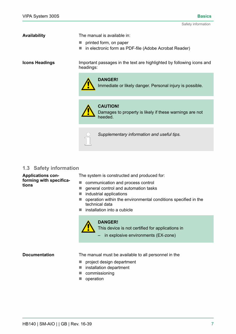
The manual is available in:n printed form, on papern in electronic form as PDF-file (Adobe Acrobat Reader)
Important passages in the text are highlighted by following icons andheadings:
DANGER!Immediate or likely danger. Personal injury is possible.
CAUTION!Damages to property is likely if these warnings are notheeded.
Supplementary information and useful tips.
1.3 Safety informationThe system is constructed and produced for:n communication and process controln general control and automation tasksn industrial applicationsn operation within the environmental conditions specified in the
technical datan installation into a cubicle
DANGER!This device is not certified for applications in– in explosive environments (EX-zone)
The manual must be available to all personnel in then project design departmentn installation departmentn commissioningn operation
Availability
Icons Headings
Applications con-forming with specifica-tions
Documentation
VIPA System 300S Basics
Safety information
HB140 | SM-AIO | | GB | Rev. 16-39 7

CAUTION!The following conditions must be met before usingor commissioning the components described inthis manual:– Hardware modifications to the process control
system should only be carried out when the systemhas been disconnected from power!
– Installation and hardware modifications only byproperly trained personnel.
– The national rules and regulations of the respectivecountry must be satisfied (installation, safety,EMC ...)
National rules and regulations apply to the disposal of the unit!Disposal
VIPA System 300SBasics
Safety information
HB140 | SM-AIO | | GB | Rev. 16-39 8
2 Assembly and installation guidelines2.1 Safety information for users
VIPA modules make use of highly integrated components in MOS-Technology. These components are extremely sensitive to over-vol-tages that can occur during electrostatic discharges. The followingsymbol is attached to modules that can be destroyed by electrostaticdischarges.
The Symbol is located on the module, the module rack or on packingmaterial and it indicates the presence of electrostatic sensitive equip-ment. It is possible that electrostatic sensitive equipment is destroyedby energies and voltages that are far less than the human thresholdof perception. These voltages can occur where persons do not dis-charge themselves before handling electrostatic sensitive modulesand they can damage components thereby, causing the module tobecome inoperable or unusable. Modules that have been damagedby electrostatic discharges can fail after a temperature change,mechanical shock or changes in the electrical load. Only the conse-quent implementation of protection devices and meticulous attentionto the applicable rules and regulations for handling the respectiveequipment can prevent failures of electrostatic sensitive modules.
Modules must be shipped in the original packing material.
When you are conducting measurements on electrostatic sensitivemodules you should take the following precautions:n Floating instruments must be discharged before use.n Instruments must be grounded.Modifying electrostatic sensitive modules you should only use sol-dering irons with grounded tips.
CAUTION!Personnel and instruments should be grounded whenworking on electrostatic sensitive modules.
2.2 OverviewWhile the standard peripheral modules are plugged-in at the right sideof the CPU, the SPEED-Bus peripheral modules are connected via aSPEED-Bus bus connector at the left side of the CPU. VIPA deliversprofile rails with integrated SPEED-Bus for 2, 6 or 10 SPEED-Busperipheral modules with different lengths.
Handling of electro-static sensitive modules
Shipping of modules
Measurements andalterations on electro-static sensitive modules
General
VIPA System 300S Assembly and installation guidelines
Overview
HB140 | SM-AIO | | GB | Rev. 16-39 9

The single modules are directly installed on a profile rail and con-nected via the backplane bus coupler. Before installing the modulesyou have to clip the backplane bus coupler to the module from thebackside. The backplane bus couplers are included in the delivery ofthe peripheral modules.
With SPEED-Bus the bus connection happens via a SPEED-Bus railintegrated in the profile rail at the left side of the CPU. Due to the par-allel SPEED-Bus not all slots must be occupied in sequence.
At slot (SLOT 1 DCDC) you may plug either a SPEED-Bus module oran additional power supply.
You may assemble the System 300 horizontally, vertically or lying.
Please regard the allowed environment temperatures:n horizontal assembly: from 0 to 60°Cn vertical assembly: from 0 to 40°Cn lying assembly: from 0 to 40°C
2.3 Installation dimensions1tier width (WxHxD) in mm: 40 x 125 x 120
Serial Standard bus
Parallel SPEED-Bus
SLOT 1 for additionalpower supply
Assembly possibilities
Dimensions Basicenclosure
VIPA System 300SAssembly and installation guidelines
Installation dimensions
HB140 | SM-AIO | | GB | Rev. 16-39 10

Dimensions
Installation dimensions
VIPA System 300S Assembly and installation guidelines
Installation dimensions
HB140 | SM-AIO | | GB | Rev. 16-39 11
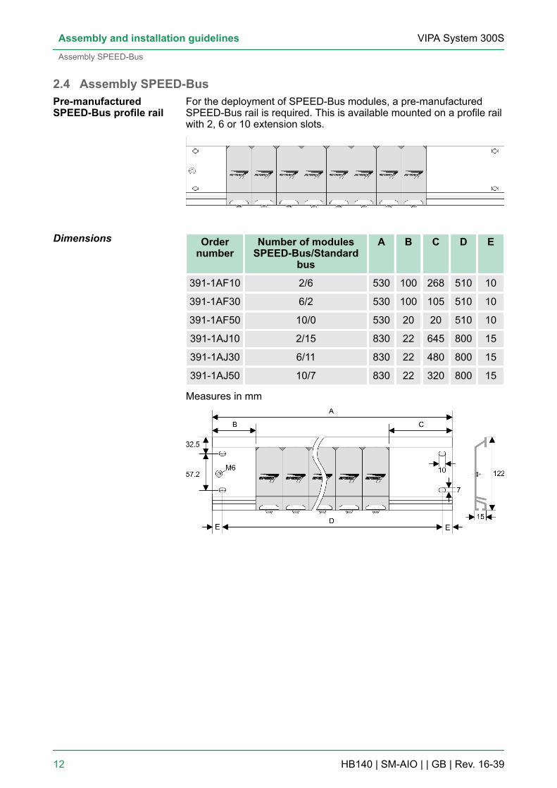
2.4 Assembly SPEED-BusFor the deployment of SPEED-Bus modules, a pre-manufacturedSPEED-Bus rail is required. This is available mounted on a profile railwith 2, 6 or 10 extension slots.
Ordernumber
Number of modulesSPEED-Bus/Standard
bus
A B C D E
391-1AF10 2/6 530 100 268 510 10
391-1AF30 6/2 530 100 105 510 10
391-1AF50 10/0 530 20 20 510 10
391-1AJ10 2/15 830 22 645 800 15
391-1AJ30 6/11 830 22 480 800 15
391-1AJ50 10/7 830 22 320 800 15
Measures in mm
Pre-manufacturedSPEED-Bus profile rail
Dimensions
VIPA System 300SAssembly and installation guidelines
Assembly SPEED-Bus
HB140 | SM-AIO | | GB | Rev. 16-39 12
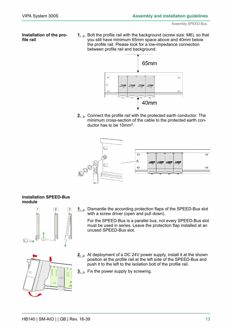
1. Bolt the profile rail with the background (screw size: M6), so thatyou still have minimum 65mm space above and 40mm belowthe profile rail. Please look for a low-impedance connectionbetween profile rail and background.
2. Connect the profile rail with the protected earth conductor. Theminimum cross-section of the cable to the protected earth con-ductor has to be 10mm2.
1. Dismantle the according protection flaps of the SPEED-Bus slotwith a screw driver (open and pull down).For the SPEED-Bus is a parallel bus, not every SPEED-Bus slotmust be used in series. Leave the protection flap installed at anunused SPEED-Bus slot.
2. At deployment of a DC 24V power supply, install it at the shownposition at the profile rail at the left side of the SPEED-Bus andpush it to the left to the isolation bolt of the profile rail.
3. Fix the power supply by screwing.
Installation of the pro-file rail
Installation SPEED-Busmodule
VIPA System 300S Assembly and installation guidelines
Assembly SPEED-Bus
HB140 | SM-AIO | | GB | Rev. 16-39 13

4. To connect the SPEED-Bus modules, plug it between the trian-gular positioning helps to a slot marked with "SLOT ..." and pullit down.
5. Only the "SLOT1 DCDC" allows you to plug-in either a SPEED-Bus module or an additional power supply.
6. Fix the CPU by screwing.
1. To deploy the SPEED7-CPU exclusively at the SPEED-Bus,plug it between the triangular positioning helps to the slotmarked with "CPU SPEED7" and pull it down.
2. Fix the CPU by screwing.
1. If also standard modules shall be plugged, take a bus couplerand click it at the CPU from behind like shown in the picture.Plug the CPU between the triangular positioning helps to the slotmarked with "CPU SPEED7" and pull it down.
2. Plug the CPU between the triangular positioning helps to theplug-in location marked with "CPU SPEED7" and pull it down.Fix the CPU by screwing.
Repeat this procedure with the peripheral modules, by clicking abackplane bus coupler, stick the module right from the modulesyou've already fixed, click it downwards and connect it with thebackplane bus coupler of the last module and bolt it.
Installation CPU withoutStandard-Bus-Modules
Installation CPU withStandard-Bus-Modules
Installation Standard-Bus-Modules
VIPA System 300SAssembly and installation guidelines
Assembly SPEED-Bus
HB140 | SM-AIO | | GB | Rev. 16-39 14

CAUTION!– The power supplies must be released before instal-
lation and repair tasks, i.e. before handling with thepower supply or with the cabling you must discon-nect current/voltage (pull plug, at fixed connectionswitch off the concerning fuse)!
– Installation and modifications only by properlytrained personnel!
2.5 Assembly standard busThe single modules are directly installed on a profile rail and con-nected via the backplane bus connector. Before installing the mod-ules you have to clip the backplane bus connector to the module fromthe backside. The backplane bus connector is delivered together withthe peripheral modules.
Order number A B C
390-1AB60 160 140 10
390-1AE80 482 466 8.3
390-1AF30 530 500 15
390-1AJ30 830 800 15
390-9BC00* 2000 Drillings only left 15*) Unit pack: 10 pieces
Measures in mm
General
Profile rail
VIPA System 300S Assembly and installation guidelines
Assembly standard bus
HB140 | SM-AIO | | GB | Rev. 16-39 15

For the communication between the modules the System 300S usesa backplane bus connector. Backplane bus connectors are includedin the delivering of the peripheral modules and are clipped at themodule from the backside before installing it to the profile rail.
Please regard the allowed environment temperatures:n horizontal assembly: from 0 to 60°Cn vertical assembly: from 0 to 50°Cn lying assembly: from 0 to 55°C
If you do not deploy SPEED-Bus modules, the assembly happenswith the following approach:1. Bolt the profile rail with the background (screw size: M6), so that
you still have minimum 65mm space above and 40mm belowthe profile rail.
2. If the background is a grounded metal or device plate, pleaselook for a low-impedance connection between profile rail andbackground.
3. Connect the profile rail with the protected earth conductor. Forthis purpose there is a bolt with M6-thread.
4. The minimum cross-section of the cable to the protected earthconductor has to be 10mm2.
5. Stick the power supply to the profile rail and pull it to the left sideto the grounding bolt of the profile rail.
6. Fix the power supply by screwing.7. Take a backplane bus connector and click it at the CPU from the
backside like shown in the picture.8. Stick the CPU to the profile rail right from the power supply and
pull it to the power supply.
Bus connector
Assembly possibilities
Approach
VIPA System 300SAssembly and installation guidelines
Assembly standard bus
HB140 | SM-AIO | | GB | Rev. 16-39 16

9. Click the CPU downwards and bolt it like shown.10. Repeat this procedure with the peripheral modules, by clicking a
backplane bus connector, stick the module right from the mod-ules you've already fixed, click it downwards and connect it withthe backplane bus connector of the last module and bolt it.
2.6 Cabling
CAUTION!– The power supplies must be released before instal-
lation and repair tasks, i.e. before handling with thepower supply or with the cabling you must discon-nect current/voltage (pull plug, at fixed connectionswitch off the concerning fuse)!
– Installation and modifications only by properlytrained personnel!
VIPA System 300S Assembly and installation guidelines
Cabling
HB140 | SM-AIO | | GB | Rev. 16-39 17

For the cabling of power supply of a CPU, a green plug with Cage-Clamp technology is deployed. The connection clamp is realized asplug that may be clipped off carefully if it is still cabled.
Here wires with a cross-section of 0.08mm2 to 2.5mm2 may be con-nected. You can use flexible wires without end case as well as stiffwires.
1 Test point for 2mm test tip2 Locking (orange) for screwdriver3 Round opening for wiresThe picture on the left side shows the cabling step by step from topview.1. For cabling you push the locking vertical to the inside with a
suiting screwdriver and hold the screwdriver in this position.2. Insert the de-isolated wire into the round opening. You may use
wires with a cross-section from 0.08mm2 to 2.5mm2
3. By removing the screwdriver the wire is connected safely withthe plug connector via a spring.
In the following the cabling of the two variants are shown.
CageClamp technology(green)
Front connectors of thein-/output modules
VIPA System 300SAssembly and installation guidelines
Cabling
HB140 | SM-AIO | | GB | Rev. 16-39 18
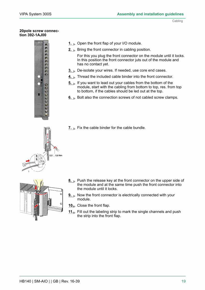
1. Open the front flap of your I/O module.2. Bring the front connector in cabling position.
For this you plug the front connector on the module until it locks.In this position the front connector juts out of the module andhas no contact yet.
3. De-isolate your wires. If needed, use core end cases.4. Thread the included cable binder into the front connector.5. If you want to lead out your cables from the bottom of the
module, start with the cabling from bottom to top, res. from topto bottom, if the cables should be led out at the top.
6. Bolt also the connection screws of not cabled screw clamps.
7. Fix the cable binder for the cable bundle.
8. Push the release key at the front connector on the upper side ofthe module and at the same time push the front connector intothe module until it locks.
9. Now the front connector is electrically connected with yourmodule.
10. Close the front flap.11. Fill out the labeling strip to mark the single channels and push
the strip into the front flap.
20pole screw connec-tion 392-1AJ00
VIPA System 300S Assembly and installation guidelines
Cabling
HB140 | SM-AIO | | GB | Rev. 16-39 19

1. Open the front flap of your I/O module.2. Bring the front connector in cabling position.
For this you plug the front connector on the module until it locks.In this position the front connector juts out of the module andhas no contact yet.
3. De-isolate your wires. If needed, use core end cases.4. If you want to lead out your cables from the bottom of the
module, start with the cabling from bottom to top, res. from topto bottom, if the cables should be led out at the top.
5. Bolt also the connection screws of not cabled screw clamps.
6. Put the included cable binder around the cable bundle and thefront connector.
7. Fix the cable binder for the cable bundle.
8. Bolt the fixing screw of the front connector.9. Now the front connector is electrically connected with your
module.10. Close the front flap.11. Fill out the labeling strip to mark the single channels and push
the strip into the front flap.
2.7 Installation guidelinesThe installation guidelines contain information about the interferencefree deployment of a PLC system. There is the description of theways, interference may occur in your PLC, how you can make surethe electromagnetic compatibility (EMC), and how you manage theisolation.
40pole screw connec-tion 392-1AM00
General
VIPA System 300SAssembly and installation guidelines
Installation guidelines
HB140 | SM-AIO | | GB | Rev. 16-39 20

Electromagnetic compatibility (EMC) means the ability of an electricaldevice, to function error free in an electromagnetic environmentwithout being interfered respectively without interfering the environ-ment.The components of VIPA are developed for the deployment in indus-trial environments and meets high demands on the EMC. Neverthe-less you should project an EMC planning before installing the compo-nents and take conceivable interference causes into account.
Electromagnetic interferences may interfere your control via differentways:n Electromagnetic fields (RF coupling)n Magnetic fields with power frequencyn Bus systemn Power supplyn Protected earth conductorDepending on the spreading medium (lead bound or lead free) andthe distance to the interference cause, interferences to your controloccur by means of different coupling mechanisms.There are:n galvanic couplingn capacitive couplingn inductive couplingn radiant coupling
In the most times it is enough to take care of some elementary rulesto guarantee the EMC. Please regard the following basic rules wheninstalling your PLC.n Take care of a correct area-wide grounding of the inactive metal
parts when installing your components.– Install a central connection between the ground and the pro-
tected earth conductor system.– Connect all inactive metal extensive and impedance-low.– Please try not to use aluminium parts. Aluminium is easily oxi-
dizing and is therefore less suitable for grounding.n When cabling, take care of the correct line routing.
– Organize your cabling in line groups (high voltage, currentsupply, signal and data lines).
– Always lay your high voltage lines and signal respectively datalines in separate channels or bundles.
– Route the signal and data lines as near as possible besideground areas (e.g. suspension bars, metal rails, tin cabinet).
What does EMC mean?
Possible interferencecauses
Basic rules for EMC
VIPA System 300S Assembly and installation guidelines
Installation guidelines
HB140 | SM-AIO | | GB | Rev. 16-39 21
n Proof the correct fixing of the lead isolation.– Data lines must be laid isolated.– Analog lines must be laid isolated. When transmitting signals
with small amplitudes the one sided laying of the isolation maybe favourable.
– Lay the line isolation extensively on an isolation/protectedearth conductor rail directly after the cabinet entry and fix theisolation with cable clamps.
– Make sure that the isolation/protected earth conductor rail isconnected impedance-low with the cabinet.
– Use metallic or metallised plug cases for isolated data lines.n In special use cases you should appoint special EMC actions.
– Consider to wire all inductivities with erase links.– Please consider luminescent lamps can influence signal lines.
n Create a homogeneous reference potential and ground all elec-trical operating supplies when possible.– Please take care for the targeted employment of the grounding
actions. The grounding of the PLC serves for protection andfunctionality activity.
– Connect installation parts and cabinets with your PLC in startopology with the isolation/protected earth conductor system.So you avoid ground loops.
– If there are potential differences between installation parts andcabinets, lay sufficiently dimensioned potential compensationlines.
Electrical, magnetically and electromagnetic interference fields areweakened by means of an isolation, one talks of absorption. Via theisolation rail, that is connected conductive with the rack, interferencecurrents are shunt via cable isolation to the ground. Here you have tomake sure, that the connection to the protected earth conductor isimpedance-low, because otherwise the interference currents mayappear as interference cause.When isolating cables you have to regard the following:n If possible, use only cables with isolation tangle.n The hiding power of the isolation should be higher than 80%.n Normally you should always lay the isolation of cables on both
sides. Only by means of the both-sided connection of the isolationyou achieve high quality interference suppression in the higherfrequency area. Only as exception you may also lay the isolationone-sided. Then you only achieve the absorption of the lower fre-quencies. A one-sided isolation connection may be convenient, if:– the conduction of a potential compensating line is not possible.– analog signals (some mV respectively µA) are transferred.– foil isolations (static isolations) are used.
n With data lines always use metallic or metallised plugs for serialcouplings. Fix the isolation of the data line at the plug rack. Do notlay the isolation on the PIN 1 of the plug bar!
n At stationary operation it is convenient to strip the insulated cableinterruption free and lay it on the isolation/protected earth con-ductor line.
Isolation of conductors
VIPA System 300SAssembly and installation guidelines
Installation guidelines
HB140 | SM-AIO | | GB | Rev. 16-39 22
n To fix the isolation tangles use cable clamps out of metal. Theclamps must clasp the isolation extensively and have well contact.
n Lay the isolation on an isolation rail directly after the entry of thecable in the cabinet. Lead the isolation further on to your PLC anddon't lay it on there again!
CAUTION!Please regard at installation!At potential differences between the grounding points,there may be a compensation current via the isolationconnected at both sides.Remedy: Potential compensation line
2.8 General data I/O modulesn Peripheral modules with recessed labelingn Dimensions of the basic enclosure:
– 1tier width: (WxHxD) in mm: 40x125x120
n Wiring by means of spring pressure connections (CageClamps) atthe front connector
n Core cross-section 0.08 ... 2.5mm2 or 1.5 mm2
n Total isolation of the wiring at module changen Potential separation of all modules to the backplane bus
2.8.1 General data
Conformity and approval
Conformity
CE 2014/35/EU Low-voltage directive
2014/30/EU EMC directive
Approval
UL Refer to Technical data
others
RoHS 2011/65/EU Product is lead-free; Restriction of the use ofcertain hazardous substances in electrical andelectronic equipment
Protection of persons and device protection
Type of protection - IP20
Electrical isolation
Structure/dimensions
Reliability
VIPA System 300S Assembly and installation guidelines
General data I/O modules > General data
HB140 | SM-AIO | | GB | Rev. 16-39 23

Protection of persons and device protection
to the field bus - electrically isolated
to the process level - electrically isolated
Insulation resistance -
Insulation voltage to reference earth
Inputs / outputs - AC / DC 50V, test voltage AC 500V
Protective measures - against short circuit
Environmental conditions to EN 61131-2
Climatic
Storage / transport EN 60068-2-14 -25…+70°C
Operation
Horizontal installation hanging EN 61131-2 0…+60°C
Horizontal installation lying EN 61131-2 0…+55°C
Vertical installation EN 61131-2 0…+50°C
Air humidity EN 60068-2-30 RH1 (without condensation, rel. humidity 10…95%)
Pollution EN 61131-2 Degree of pollution 2
Installation altitude max. - 2000m
Mechanical
Oscillation EN 60068-2-6 1g, 9Hz ... 150Hz
Shock EN 60068-2-27 15g, 11ms
Mounting conditions
Mounting place - In the control cabinet
Mounting position - Horizontal and vertical
EMC Standard Comment
Emitted interfer-ence
EN 61000-6-4 Class A (Industrial area)
Noise immunityzone B
EN 61000-6-2 Industrial area
EN 61000-4-2 ESD8kV at air discharge (degree of severity 3),4kV at contact discharge (degree of severity2)
VIPA System 300SAssembly and installation guidelines
General data I/O modules > General data
HB140 | SM-AIO | | GB | Rev. 16-39 24
EMC Standard Comment
EN 61000-4-3 HF field immunity (casing)80MHz … 1000MHz, 10V/m, 80% AM (1kHz)1.4GHz ... 2.0GHz, 3V/m, 80% AM (1kHz)2GHz ... 2.7GHz, 1V/m, 80% AM (1kHz)
EN 61000-4-6 HF conducted150kHz … 80MHz, 10V, 80% AM (1kHz)
EN 61000-4-4 Burst, degree of severity 3
EN 61000-4-5 Surge, installation class 3 **) Due to the high-energetic single pulses with Surge an appropriate external protective circuit with lightning protection elements like conductors
for lightning and overvoltage is necessary.
VIPA System 300S Assembly and installation guidelines
General data I/O modules > General data
HB140 | SM-AIO | | GB | Rev. 16-39 25
3 Analog Input Modules3.1 Principles
For analog signals you have to use isolated cables to reduce interfer-ence. The cable screening should be grounded at both ends. If thereare differences in the potential between the cable ends, there mayoccur a potential compensating current that could disturb the analogsignals. In this case you should ground the cable screening only atone end.
The analog input modules provide variant connecting possibilities for:n Current sensorn Voltage senorn Resistance thermometern Thermocouplen Resistors
Please take care of the correct polarity when installingthe measuring transducer! Please install short circuitsat non-used inputs by connecting the positive contactwith the channel ground of the according channel.
The analog input modules from VIPA do not have any measuringrange plug. The modules are parameterized via the hardware config-urator or during runtime via SFCs.
The modules that are described in this chapter except the 331-1KF01offer diagnostics functions. The following errors may cause diagnos-tics:n Error in the project engineering res. parameterizationn Wire break at current measuringn Measuring range overstepn Measuring range shortfalln Common Mode Errorn Lost process interruptn Failure of the external power supplyFor diagnostic evaluation during runtime, you may use the SFCs 51and 59. They allow you to request detailed diagnostic information andto react to it.
Cables for analog sig-nals
Connecting test probes
Parameterization
Diagnostic functions
VIPA System 300SAnalog Input Modules
Principles
HB140 | SM-AIO | | GB | Rev. 16-39 26
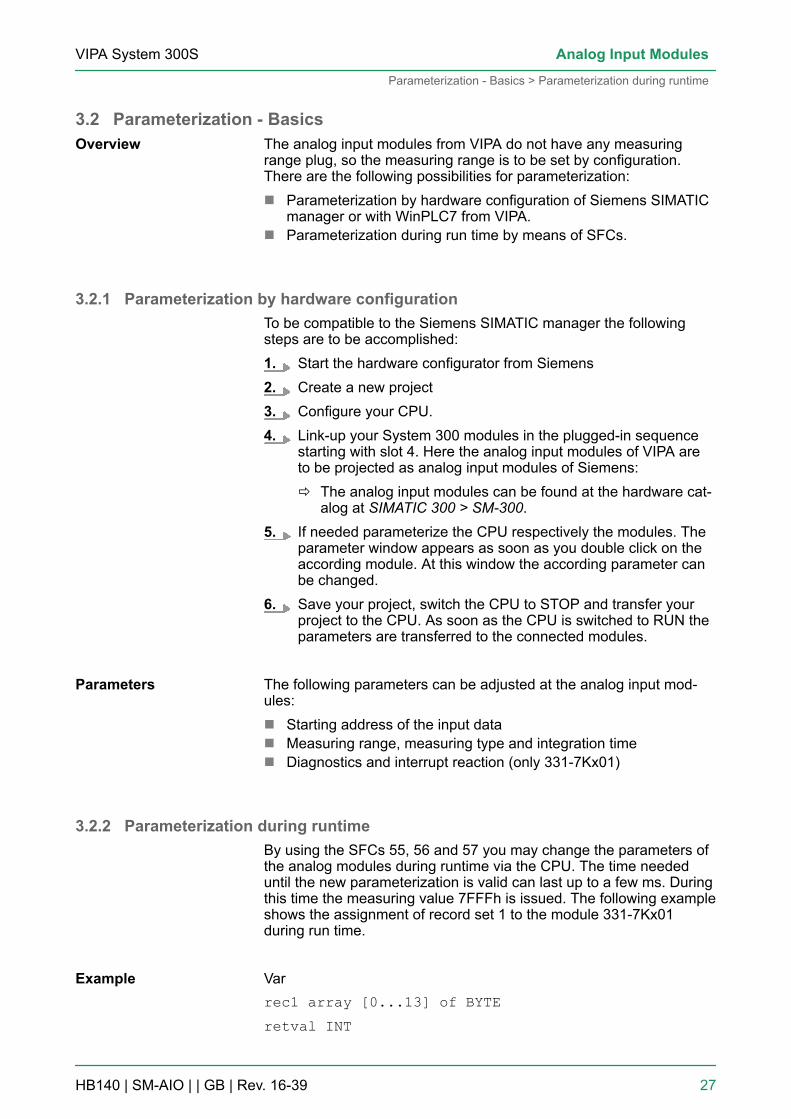
3.2 Parameterization - BasicsThe analog input modules from VIPA do not have any measuringrange plug, so the measuring range is to be set by configuration.There are the following possibilities for parameterization:n Parameterization by hardware configuration of Siemens SIMATIC
manager or with WinPLC7 from VIPA.n Parameterization during run time by means of SFCs.
3.2.1 Parameterization by hardware configurationTo be compatible to the Siemens SIMATIC manager the followingsteps are to be accomplished:1. Start the hardware configurator from Siemens2. Create a new project3. Configure your CPU.4. Link-up your System 300 modules in the plugged-in sequence
starting with slot 4. Here the analog input modules of VIPA areto be projected as analog input modules of Siemens:
ð The analog input modules can be found at the hardware cat-alog at SIMATIC 300 > SM-300.
5. If needed parameterize the CPU respectively the modules. Theparameter window appears as soon as you double click on theaccording module. At this window the according parameter canbe changed.
6. Save your project, switch the CPU to STOP and transfer yourproject to the CPU. As soon as the CPU is switched to RUN theparameters are transferred to the connected modules.
The following parameters can be adjusted at the analog input mod-ules:n Starting address of the input datan Measuring range, measuring type and integration timen Diagnostics and interrupt reaction (only 331-7Kx01)
3.2.2 Parameterization during runtimeBy using the SFCs 55, 56 and 57 you may change the parameters ofthe analog modules during runtime via the CPU. The time neededuntil the new parameterization is valid can last up to a few ms. Duringthis time the measuring value 7FFFh is issued. The following exampleshows the assignment of record set 1 to the module 331-7Kx01during run time.
Varrec1 array [0...13] of BYTEretval INT
Overview
Parameters
Example
VIPA System 300S Analog Input Modules
Parameterization - Basics > Parameterization during runtime
HB140 | SM-AIO | | GB | Rev. 16-39 27

busy BOOLSet Record set 1:L B#16#0 //Diagnostic disabledT #rec1[0]L B#16#AA //Interference freq. suppressionT #rec1[1]L B#16#D4 //Meas. range Type S: 0100b
T #rec1[2] //Meas. type: Thermocouple
T #rec1[3] //Compensation internal: 1101b
T #rec1[4] //for all channelsT #rec1[5]L B#16#7F //Upper limit value
T #rec1[6] //channel 0: 7FFFhL B#16#FFT #rec1[7]L B#16#80 //Lower limit value
T #rec1[12] //channel 2: 8000hL B#16#00T #rec1[13]
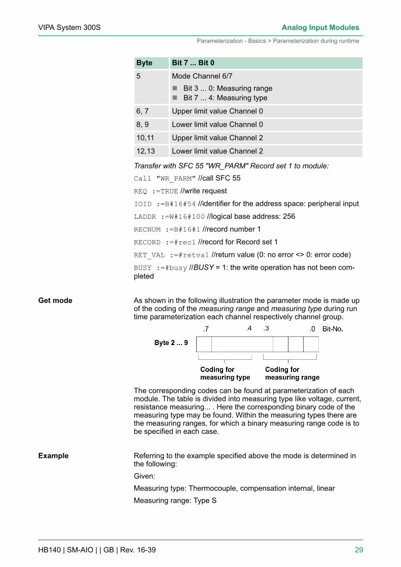
Record set 1 from module 331-7Kx01:
Byte Bit 7 ... Bit 0
0 n Bit 5 ... 0: reservedn Bit 6: Diagnosis interrupt releasen Bit 7: Process interrupt release
1 Interference freq. suppressionn Bit 0, 1: Channel 0/1n Bit 2, 3: Channel 2/3n Bit 4, 5: Channel 4/5n Bit 6, 7: Channel 6/7
2 Mode Channel 0/1n Bit 3 ... 0: Measuring rangen Bit 7 ... 4: Measuring type
3 Mode Channel 2/3n Bit 3 ... 0: Measuring rangen Bit 7 ... 4: Measuring type
4 Mode Channel 4/5n Bit 3 ... 0: Measuring rangen Bit 7 ... 4: Measuring type
VIPA System 300SAnalog Input Modules
Parameterization - Basics > Parameterization during runtime
HB140 | SM-AIO | | GB | Rev. 16-39 28
Byte Bit 7 ... Bit 0
5 Mode Channel 6/7n Bit 3 ... 0: Measuring rangen Bit 7 ... 4: Measuring type
6, 7 Upper limit value Channel 0
8, 9 Lower limit value Channel 0
10,11 Upper limit value Channel 2
12,13 Lower limit value Channel 2
Transfer with SFC 55 "WR_PARM" Record set 1 to module:Call "WR_PARM" //call SFC 55
REQ :=TRUE //write request
IOID :=B#16#54 //identifier for the address space: peripheral input
LADDR :=W#16#100 //logical base address: 256
RECNUM :=B#16#1 //record number 1
RECORD :=#rec1 //record for Record set 1
RET_VAL :=#retval //return value (0: no error <> 0: error code)
BUSY :=#busy //BUSY = 1: the write operation has not been com-pleted
As shown in the following illustration the parameter mode is made upof the coding of the measuring range and measuring type during runtime parameterization each channel respectively channel group.
The corresponding codes can be found at parameterization of eachmodule. The table is divided into measuring type like voltage, current,resistance measuring... . Here the corresponding binary code of themeasuring type may be found. Within the measuring types there arethe measuring ranges, for which a binary measuring range code is tobe specified in each case.
Referring to the example specified above the mode is determined inthe following:Given:Measuring type: Thermocouple, compensation internal, linearMeasuring range: Type S
Get mode
Example
VIPA System 300S Analog Input Modules
Parameterization - Basics > Parameterization during runtime
HB140 | SM-AIO | | GB | Rev. 16-39 29

For the module 331-7Kx01 results from the table in the case of "Ther-mocouple with compensation internal, linear" the binary coding formeasuring type: 1101b. For Measuring range "Type S" the binarymeasuring range coding results as: 0100b.
CAUTION!Please regard that the modules described here do nothave hardware precautions against wrong parameteri-zation res. wrong wiring. The setting of the accordingmeasuring range is exclusively at the project engi-neering. For example, the modules may get a defect ifyou connect a voltage at parameterized current meas-uring. At the project engineering you should be verycareful. Please regard also that disconnecting res. con-necting during operation is not possible!
3.3 331-1KF01 - AI 8x13BitThe analog input module transforms analog signals from the processinto digital signals for the internal processing. The module is pin andfunction compatible to the known module from Siemens. Pluggingand unplugging during operation, is not supported. Voltage and cur-rent encoders, resistors and resistor thermometers may be connectedas sensorsn 8 inputsn Measuring value resolution 12bit + signn Isolated to the backplane bus
After Power ON the module has the following default configuration.These can be changed by hardware configuration.n measuring range: ±10V for all channelsn integration time: 60ms
Properties
Default configuration
VIPA System 300SAnalog Input Modules
331-1KF01 - AI 8x13Bit
HB140 | SM-AIO | | GB | Rev. 16-39 30

1 LEDs (not active)2 flap with labeling strip3 contact bar4 flap opened with inner label
Structure
VIPA System 300S Analog Input Modules
331-1KF01 - AI 8x13Bit
HB140 | SM-AIO | | GB | Rev. 16-39 31
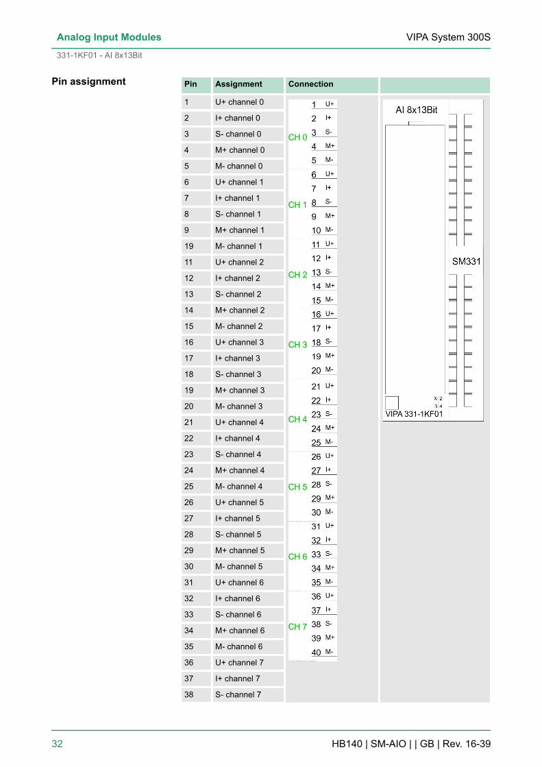
Pin Assignment Connection
1 U+ channel 0
2 I+ channel 0
3 S- channel 0
4 M+ channel 0
5 M- channel 0
6 U+ channel 1
7 I+ channel 1
8 S- channel 1
9 M+ channel 1
19 M- channel 1
11 U+ channel 2
12 I+ channel 2
13 S- channel 2
14 M+ channel 2
15 M- channel 2
16 U+ channel 3
17 I+ channel 3
18 S- channel 3
19 M+ channel 3
20 M- channel 3
21 U+ channel 4
22 I+ channel 4
23 S- channel 4
24 M+ channel 4
25 M- channel 4
26 U+ channel 5
27 I+ channel 5
28 S- channel 5
29 M+ channel 5
30 M- channel 5
31 U+ channel 6
32 I+ channel 6
33 S- channel 6
34 M+ channel 6
35 M- channel 6
36 U+ channel 7
37 I+ channel 7
38 S- channel 7
Pin assignment
VIPA System 300SAnalog Input Modules
331-1KF01 - AI 8x13Bit
HB140 | SM-AIO | | GB | Rev. 16-39 32

Pin Assignment Connection
39 M+ channel 7
40 M- channel 7
The following illustration shows the connection options for the dif-ferent measuring ranges. The assignment to the measuring ranges isto find in the column "Conn." of the table "Measuring" on the nextpages.
Please take care that the maximum permissiblecommon-mode voltage of 2V between the inputs atconnection of voltage and current giver is notexceeded. To avoid wrong measurements you connectthe individual connections M- with each other.At measuring of resistance and resistance thermome-ters a connection of the M- connections is not required.Modules are not released for common GND.When using the temperature measurement by thermalresistance (PT100, NI100, NI1000) of the channelassociated with the parameter "temperature coeffi-cient" must be set as under "Structure parameter byte"described. Ä Chapter 3.3.1.1 ‘Structure of parameterbyte (Record set 1)’ on page 34Temporarily not used inputs with activated channelmust be connected with the concerning ground. Whennot used channels are deactivated this is not neces-sary.
Analog values are exclusively processed by the CPU in a binaryformat. For this the analog module transforms every process signalinto a digital and transfers this as word to the CPU. At similar nominalrange, the digitalized analog value for in- and output is identical.
Because the resolution of the module is 12Bit plus sign bit, the notused low value positions (3 Bit) are filled with "0".For the sign bit is valid:Bit 15 = "0" à positive valueBit 15 = "1" à negative value
Wiring diagrams
Representation ofanalog values
Resolution
VIPA System 300S Analog Input Modules
331-1KF01 - AI 8x13Bit
HB140 | SM-AIO | | GB | Rev. 16-39 33
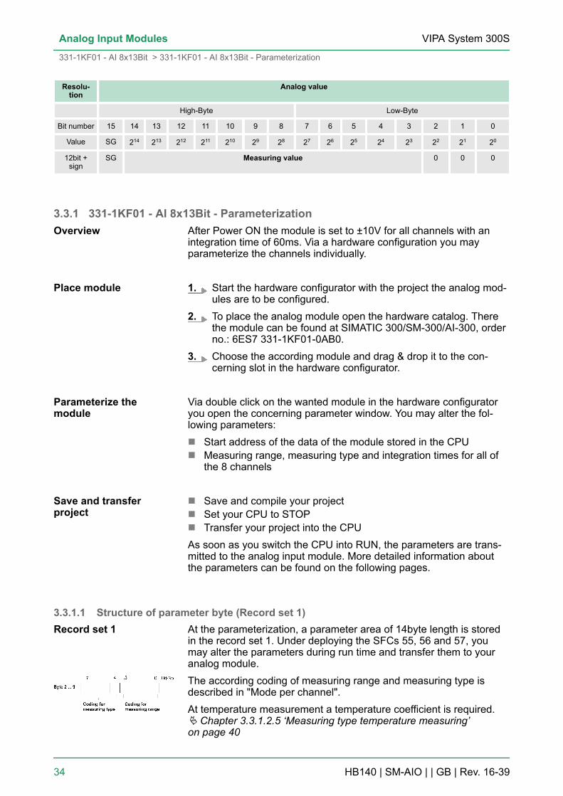
Resolu-tion
Analog value
High-Byte Low-Byte
Bit number 15 14 13 12 11 10 9 8 7 6 5 4 3 2 1 0
Value SG 214 213 212 211 210 29 28 27 26 25 24 23 22 21 20
12bit +sign
SG Measuring value 0 0 0
3.3.1 331-1KF01 - AI 8x13Bit - ParameterizationAfter Power ON the module is set to ±10V for all channels with anintegration time of 60ms. Via a hardware configuration you mayparameterize the channels individually.
1. Start the hardware configurator with the project the analog mod-ules are to be configured.
2. To place the analog module open the hardware catalog. Therethe module can be found at SIMATIC 300/SM-300/AI-300, orderno.: 6ES7 331-1KF01-0AB0.
3. Choose the according module and drag & drop it to the con-cerning slot in the hardware configurator.
Via double click on the wanted module in the hardware configuratoryou open the concerning parameter window. You may alter the fol-lowing parameters:n Start address of the data of the module stored in the CPUn Measuring range, measuring type and integration times for all of
the 8 channels
n Save and compile your projectn Set your CPU to STOPn Transfer your project into the CPUAs soon as you switch the CPU into RUN, the parameters are trans-mitted to the analog input module. More detailed information aboutthe parameters can be found on the following pages.
3.3.1.1 Structure of parameter byte (Record set 1)At the parameterization, a parameter area of 14byte length is storedin the record set 1. Under deploying the SFCs 55, 56 and 57, youmay alter the parameters during run time and transfer them to youranalog module.The according coding of measuring range and measuring type isdescribed in "Mode per channel".At temperature measurement a temperature coefficient is required.Ä Chapter 3.3.1.2.5 ‘Measuring type temperature measuring’on page 40
Overview
Place module
Parameterize themodule
Save and transferproject
Record set 1
VIPA System 300SAnalog Input Modules
331-1KF01 - AI 8x13Bit > 331-1KF01 - AI 8x13Bit - Parameterization
HB140 | SM-AIO | | GB | Rev. 16-39 34

Record set 1 (Byte 0 to 13):
Byte Bit 7 ... Bit 0
0 Temperature measuring:0000 0000b: Grad Celsius0000 1000b: Grad Fahrenheit0001 0000b: Kelvin
1 Interference frequency suppression:0000 0001b: 60Hz (50ms Integration time)0000 0010b: 50Hz (60ms Integration time))
2 Mode channel 0n Bit 3 ... 0: Measuring rangen Bit 7 ... 4: Measuring type
3 Mode channel 1n Bit 3 ... 0: Measuring rangen Bit 7 ... 4: Measuring type
4 Mode channel 2n Bit 3 ... 0: Measuring rangen Bit 7 ... 4: Measuring type
5 Mode channel 3n Bit 3 ... 0: Measuring rangen Bit 7 ... 4: Measuring type
6 Mode channel 4n Bit 3 ... 0: Measuring rangen Bit 7 ... 4: Measuring type
7 Mode channel 5n Bit 3 ... 0: Measuring rangen Bit 7 ... 4: Measuring type
8 Mode channel 6n Bit 3 ... 0: Measuring rangen Bit 7 ... 4: Measuring type
9 Mode channel 7n Bit 3 ... 0: Measuring rangen Bit 7 ... 4: Measuring type
10 Temperature coefficient:n Bit 3 ... 0: channel 1n Bit 7 ... 4: channel 0
11 Temperature coefficient::n Bit 3 ... 0: channel 3n Bit 7 ... 4: channel 2
VIPA System 300S Analog Input Modules
331-1KF01 - AI 8x13Bit > 331-1KF01 - AI 8x13Bit - Parameterization
HB140 | SM-AIO | | GB | Rev. 16-39 35

Byte Bit 7 ... Bit 0
12 Temperature coefficient::n Bit 3 ... 0: channel 5n Bit 7 ... 4: channel 4
13 Temperature coefficient::n Bit 3 ... 0: channel 7n Bit 7 ... 4: channel 6
3.3.1.2 Measuring types and ranges
The following section shows an overview of all measuring types andranges plus binary coding for the parameterization. Additionally, thewiring diagram assigned to the measuring range is shown in brackets.
To deactivate a channel the code 0000 0000 is used.
3.3.1.2.1 Measuring type Voltage measuringMeasuring type coding: 0001b
Measuringrange(Connection)
Measuring range / Representation Measuringrange coding
+/- 50mV(Connection 3)
58.79mV= End overdrive region (32511)- 50...50mV = Nominal range (-27648...27648)- 58.79mV = End underdrive region (-32512)
1011b
+/- 500mV(Connection 3)
587.9mV = End overdrive region (32511)- 500...500mV = Nominal range (-27648...27648)- 587.9mV = End underdrive region (-32512)
0011b
Mode per Channel
VIPA System 300SAnalog Input Modules
331-1KF01 - AI 8x13Bit > 331-1KF01 - AI 8x13Bit - Parameterization
HB140 | SM-AIO | | GB | Rev. 16-39 36
Measuringrange(Connection)
Measuring range / Representation Measuringrange coding
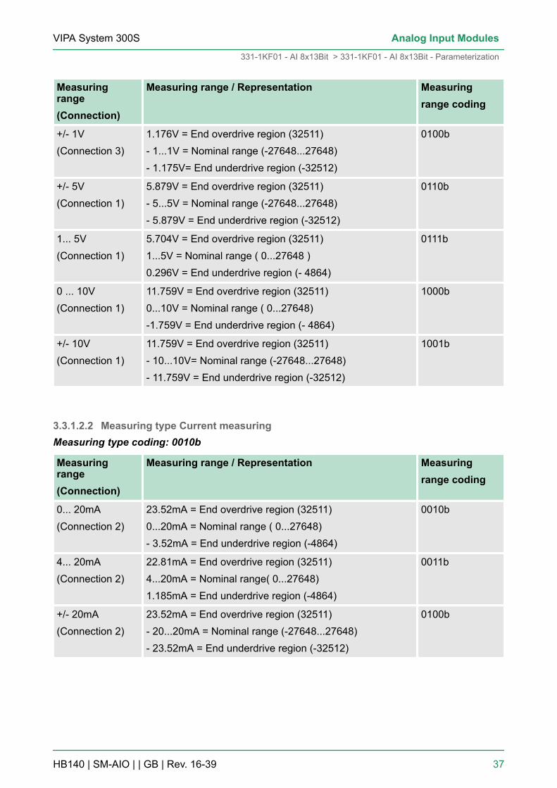
+/- 1V(Connection 3)
1.176V = End overdrive region (32511)- 1...1V = Nominal range (-27648...27648)- 1.175V= End underdrive region (-32512)
0100b
+/- 5V(Connection 1)
5.879V = End overdrive region (32511)- 5...5V = Nominal range (-27648...27648)- 5.879V = End underdrive region (-32512)
0110b
1... 5V(Connection 1)
5.704V = End overdrive region (32511)1...5V = Nominal range ( 0...27648 )0.296V = End underdrive region (- 4864)
0111b
0 ... 10V(Connection 1)
11.759V = End overdrive region (32511)0...10V = Nominal range ( 0...27648)-1.759V = End underdrive region (- 4864)
1000b
+/- 10V(Connection 1)
11.759V = End overdrive region (32511)- 10...10V= Nominal range (-27648...27648)- 11.759V = End underdrive region (-32512)
1001b
3.3.1.2.2 Measuring type Current measuringMeasuring type coding: 0010b
Measuringrange(Connection)
Measuring range / Representation Measuringrange coding
0... 20mA(Connection 2)
23.52mA = End overdrive region (32511)0...20mA = Nominal range ( 0...27648)- 3.52mA = End underdrive region (-4864)
0010b
4... 20mA(Connection 2)
22.81mA = End overdrive region (32511)4...20mA = Nominal range( 0...27648)1.185mA = End underdrive region (-4864)
0011b
+/- 20mA(Connection 2)
23.52mA = End overdrive region (32511)- 20...20mA = Nominal range (-27648...27648)- 23.52mA = End underdrive region (-32512)
0100b
VIPA System 300S Analog Input Modules
331-1KF01 - AI 8x13Bit > 331-1KF01 - AI 8x13Bit - Parameterization
HB140 | SM-AIO | | GB | Rev. 16-39 37
3.3.1.2.3 Measuring type Resistance measuringMeasuring type coding: 0101b
Measuringrange(Connection)
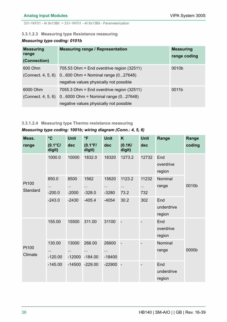
Measuring range / Representation Measuringrange coding
600 Ohm(Connect. 4, 5, 6)
705.53 Ohm = End overdrive region (32511)0...600 Ohm = Nominal range (0...27648)negative values physically not possible
0010b
6000 Ohm(Connect. 4, 5, 6)
7055.3 Ohm = End overdrive region (32511)0...6000 Ohm = Nominal range (0...27648)negative values physically not possible
0011b
3.3.1.2.4 Measuring type Thermo resistance measuringMeasuring type coding: 1001b; wiring diagram (Conn.: 4, 5, 6)
Meas.range
°C(0.1°C/digit)
Unitdec
°F(0.1°F/digit)
Unitdec
K(0.1K/digit)
Unitdec
Range Rangecoding
Pt100Standard
1000.0 10000 1832.0 18320 1273.2 12732 Endoverdriveregion
0010b850.0...-200.0
8500...-2000
1562...-328.0
15620...-3280
1123.2...73.2
11232...732
Nominalrange
-243.0 -2430 -405.4 -4054 30.2 302 Endunderdriveregion
Pt100Climate
155.00 15500 311.00 31100 - - Endoverdriveregion
0000b130.00...-120.00
13000...-12000
266.00...-184.00
26600...-18400
- - Nominalrange
-145.00 -14500 -229.00 -22900 - - Endunderdriveregion
VIPA System 300SAnalog Input Modules
331-1KF01 - AI 8x13Bit > 331-1KF01 - AI 8x13Bit - Parameterization
HB140 | SM-AIO | | GB | Rev. 16-39 38

Meas.range
°C(0.1°C/digit)
Unitdec
°F(0.1°F/digit)
Unitdec
K(0.1K/digit)
Unitdec
Range Rangecoding
Ni100Standard
295.0 2950 563.0 5630 568.2 5682 Endoverdriveregion
0011b
250.0...- 60.0
2500...-600
482.0...- 76.0
4820...-760
523.2...213.2
5232...2132
Nominalrange
-105.0 -1050 -157.0 -1570 168.2 1682 Endunderdriveregion
Ni100Climate
295.00 29500 327.66 32766 - - Endoverdriveregion
0001b250.00...-60.00
25000...-6000
280.00...-76.00
28000...7600
- - Nominalrange
-105.00 -10500 -157.00 -15700 - - Endunderdriveregion
Ni 1000 /LG-Ni 1000Standard
295.0 2950 563.0 5630 568.2 5682 Endoverdriveregion
0110b250.0...-60.0
2500...-600
482.0...-76.0
4820...-760
523.2...213.2
5232...2132
Nominalrange
-105.0 -1050 -157.0 -1570 168.2 1682 Endunderdriveregion
Ni 1000 /LG-Ni 1000Climate
295.00 29500 327.66 32766 - - Endoverdriveregion
1010b
VIPA System 300S Analog Input Modules
331-1KF01 - AI 8x13Bit > 331-1KF01 - AI 8x13Bit - Parameterization
HB140 | SM-AIO | | GB | Rev. 16-39 39

Meas.range
°C(0.1°C/digit)
Unitdec
°F(0.1°F/digit)
Unitdec
K(0.1K/digit)
Unitdec
Range Rangecoding
250.00...-60.00
25000...-6000
280.00...-76.00
28000...7600
- - Nominalrange
-105.00 -10500 -157.00 -15700 - - Endunderdriveregion
When exceeding the overdrive region 32767 (7FFFh) is issued, fallingbelow the underdrive region -32768 (8000h) is issued.
3.3.1.2.5 Measuring type temperature measuring
At temperature measurement via thermo resistance(PT100, NI100, NI1000) always the temperature coef-ficient to the according channel is required.
The table shows the according coefficient:
Measurementrange
Temperature coefficient Coding eachchannel
Pt 100 Pt 0.003850Ω/Ω/°C(ITS-90)
0100b
Ni100Ni1000
Ni 0.006180Ω/Ω/°C 1000b
LG-Ni 1000 Ni 0.005000Ω/Ω/°C 1010b
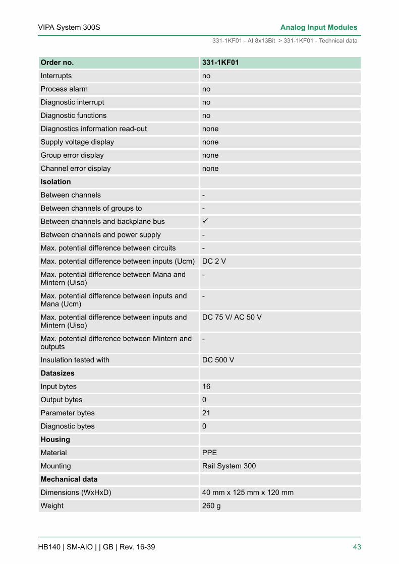
3.3.2 331-1KF01 - Technical data
Order no. 331-1KF01
Type SM 331
SPEED-Bus -
Current consumption/power loss
Current consumption from backplane bus 255 mA
Power loss 1.3 W
Technical data analog inputs
Number of inputs 8
VIPA System 300SAnalog Input Modules
331-1KF01 - AI 8x13Bit > 331-1KF01 - Technical data
HB140 | SM-AIO | | GB | Rev. 16-39 40

Order no. 331-1KF01
Cable length, shielded 50 m
Rated load voltage -
Current consumption from load voltage L+(without load)
-
Voltage inputs ü
Min. input resistance (voltage range) 100 kΩ
Input voltage ranges -50 mV ... +50 mV-500 mV ... +500 mV-1 V ... +1 V-5 V ... +5 V0 V ... +10 V-10 V ... +10 V+1 V ... +5 V
Operational limit of voltage ranges +/-0.5% ... +/-0.6%
Operational limit of voltage ranges with SFU -
Basic error limit voltage ranges +/-0.3% ... +/-0.4%
Basic error limit voltage ranges with SFU -
Destruction limit voltage max. 30V
Current inputs ü
Max. input resistance (current range) 100 Ω
Input current ranges -20 mA ... +20 mA0 mA ... +20 mA+4 mA ... +20 mA
Operational limit of current ranges +/-0.5%
Operational limit of current ranges with SFU -
Grundfehlergrenze Strombereiche +/-0.3%
Radical error limit current ranges with SFU -
Destruction limit current inputs (electrical cur-rent)
max. 40mA
Destruction limit current inputs (voltage) max. 15V
Resistance inputs ü
Resistance ranges 0 ... 600 Ohm0 ... 6000 Ohm
Operational limit of resistor ranges +/-0.5%
Operational limit of resistor ranges with SFU -
VIPA System 300S Analog Input Modules
331-1KF01 - AI 8x13Bit > 331-1KF01 - Technical data
HB140 | SM-AIO | | GB | Rev. 16-39 41

Order no. 331-1KF01
Basic error limit +/-0.3%
Basic error limit with SFU -
Destruction limit resistance inputs max. 15V
Resistance thermometer inputs ü
Resistance thermometer ranges Pt100Ni100Ni1000
Operational limit of resistance thermometerranges
+/-1K ... +/-1.2K
Operational limit of resistance thermometerranges with SFU
-
Basic error limit thermoresistor ranges +/-0.8K
Basic error limit thermoresistor ranges withSFU
-
Destruction limit resistance thermometer inputs max. 15V
Thermocouple inputs -
Thermocouple ranges -
Operational limit of thermocouple ranges -
Operational limit of thermocouple ranges withSFU
-
Basic error limit thermoelement ranges -
Basic error limit thermoelement ranges withSFU
-
Destruction limit thermocouple inputs -
Programmable temperature compensation -
External temperature compensation -
Internal temperature compensation -
Temperature error internal compensation -
Technical unit of temperature measurement °C, °F, K
Resolution in bit 13
Measurement principle Sigma-Delta
Basic conversion time 61 ms/51 ms / channel
Noise suppression for frequency 50 Hz/60 Hz
Initial data size 16 Byte
Status information, alarms, diagnostics
Status display none
VIPA System 300SAnalog Input Modules
331-1KF01 - AI 8x13Bit > 331-1KF01 - Technical data
HB140 | SM-AIO | | GB | Rev. 16-39 42
Order no. 331-1KF01
Interrupts no
Process alarm no
Diagnostic interrupt no
Diagnostic functions no
Diagnostics information read-out none
Supply voltage display none
Group error display none
Channel error display none
Isolation
Between channels -
Between channels of groups to -
Between channels and backplane bus ü
Between channels and power supply -
Max. potential difference between circuits -
Max. potential difference between inputs (Ucm) DC 2 V
Max. potential difference between Mana andMintern (Uiso)
-
Max. potential difference between inputs andMana (Ucm)
-
Max. potential difference between inputs andMintern (Uiso)
DC 75 V/ AC 50 V
Max. potential difference between Mintern andoutputs
-
Insulation tested with DC 500 V
Datasizes
Input bytes 16
Output bytes 0
Parameter bytes 21
Diagnostic bytes 0
Housing
Material PPE
Mounting Rail System 300
Mechanical data
Dimensions (WxHxD) 40 mm x 125 mm x 120 mm
Weight 260 g
VIPA System 300S Analog Input Modules
331-1KF01 - AI 8x13Bit > 331-1KF01 - Technical data
HB140 | SM-AIO | | GB | Rev. 16-39 43

Order no. 331-1KF01
Environmental conditions
Operating temperature 0 °C to 60 °C
Storage temperature -25 °C to 70 °C
Certifications
UL certification yes
KC certification yes
Additional Technical data
Order number 331-1KF01
Voltages, Currents, Potentials
Constant current for resistance-type sensor
- resistance thermometer and resistance meas-urement 0 ... 600W
0.83mA
- resistance measurement 0 ... 6kW 0.25mA
Analog value generation
Integration time / conversion time / resolution(per channel)
- programmable yes
- Integration time in ms 60ms 50ms
additional conversion time for measuring resist-ance in ms
61ms 51ms
Suppression of interference, limits error
Noises suppression for f=n x (f1 ±1%) (f1=inter-ference frequency, n=1,2,...)
- Common-mode interference (UCM < 2V) > 86dB
- Series-mode noise (peak value of noise <nominal value of input range
> 40dB
Crosstalk between the inputs > 50dB
Temperature error (with reference to the inputrange)
±0.005%/K
Linearity error (with reference to the inputrange)
±0.02%
Repeatability (in steady state at 25°C, with ref-erence to the input range)
±0.05%
Data for selecting a sensor Input range Input resistance
- Voltage ± 50mV, ± 500mV, ± 1V 100MW
VIPA System 300SAnalog Input Modules
331-1KF01 - AI 8x13Bit > 331-1KF01 - Technical data
HB140 | SM-AIO | | GB | Rev. 16-39 44
Order number 331-1KF01
±5V, 1...5V, ±10V,0...10V
100kW
- Current ±20mA, 0...20mA,4...20mA
100W
- Resistors 0 ... 600W, 0 ... 6kW 100MW
- Resistance thermometer Pt100 Standard / Cli-mate
100MW
Ni100, Ni1000, LG-Ni1000 Standard / Cli-mate
100MW
Maximum input voltage for voltage input U+(destruction limit)
max. 30V
Maximum input voltage for voltage input M+(destruction limit)
max. 12V30V for max. 1s
Maximum input current for current input L+(destruction limit)
40mA
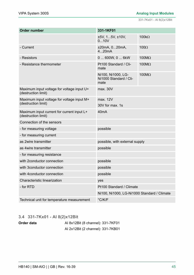
Connection of the sensors
- for measuring voltage possible
- for measuring current
as 2wire transmitter possible, with external supply
as 4wire transmitter possible
- for measuring resistance
with 2conductor connection possible
with 3conductor connection possible
with 4conductor connection possible
Characteristic linearization yes
- for RTD Pt100 Standard / Climate
Ni100, Ni1000, LG-Ni1000 Standard / Climate
Technical unit for temperature measurement °C/K/F
3.4 331-7Kx01 - AI 8(2)x12BitAI 8x12Bit (8 channel): 331-7KF01AI 2x12Bit (2 channel): 331-7KB01
Order data
VIPA System 300S Analog Input Modules
331-7Kx01 - AI 8(2)x12Bit
HB140 | SM-AIO | | GB | Rev. 16-39 45

The analog input modules transform analog signals from the processinto digital signals for the internal processing. The modules are pinand function compatible to the modules from Siemens with the samename. Please regard that contrary to the Siemens modules the mod-ules specified here do not have any measuring range plug. The atti-tude of the designated measuring range exclusively takes placeduring software project engineering. Plugging and unplugging duringoperation, is not supported. Voltage and current sensors, thermocou-ples, resistors and resistance thermometers may be connected.n 8 inputs in 4 channel group (331-7KF01)n 2 inputs in 1 channel group (331-7KB01)n Measuring value resolution 14Bit + signn Configurable diagnostic and process interruptn Isolated to the backplane bus
After Power ON both modules have the following default configura-tion. These can be changed by hardware configuration:n Measuring range: ±10V for all channelsn Integration time: 20msn Interrupts deactivated
1 LEDs2 flap with labeling strip3 contact bar4 flap opened with inner label
Properties
Measuring range afterPower ON
Structure
VIPA System 300SAnalog Input Modules
331-7Kx01 - AI 8(2)x12Bit
HB140 | SM-AIO | | GB | Rev. 16-39 46
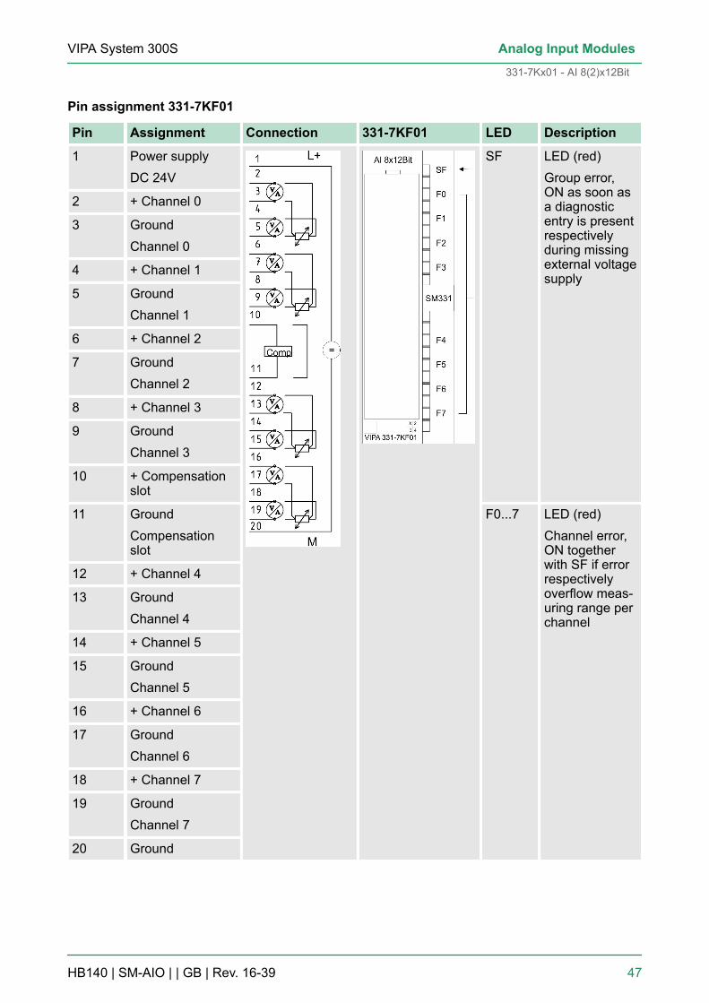
Pin assignment 331-7KF01
Pin Assignment Connection 331-7KF01 LED Description
1 Power supplyDC 24V
SF LED (red)Group error,ON as soon asa diagnosticentry is presentrespectivelyduring missingexternal voltagesupply
2 + Channel 0
3 GroundChannel 0
4 + Channel 1
5 GroundChannel 1
6 + Channel 2
7 GroundChannel 2
8 + Channel 3
9 GroundChannel 3
10 + Compensationslot
11 GroundCompensationslot
F0...7 LED (red)Channel error,ON togetherwith SF if errorrespectivelyoverflow meas-uring range perchannel
12 + Channel 4
13 GroundChannel 4
14 + Channel 5
15 GroundChannel 5
16 + Channel 6
17 GroundChannel 6
18 + Channel 7
19 GroundChannel 7
20 Ground
VIPA System 300S Analog Input Modules
331-7Kx01 - AI 8(2)x12Bit
HB140 | SM-AIO | | GB | Rev. 16-39 47

Pin assignment LED 331-7KB01
Pin Assignment Connection 331-7KB01 LED Description
1 Power supplyDC 24V
SF LED (red)Group error,ON as soon asa diagnosticentry is presentrespectivelyduring missingexternal voltagesupply
2 + Channel 0
3 GroundChannel 0
4 + Channel 1
5 GroundChannel 1
6 n.c.
. .
. .
9 n.c.
10 + Compensationslot
11 GroundCompensationslot
F0F1
LED (red)Channel error,ON togetherwith SF if errorrespectivelyoverflow meas-uring range perchannel
12 n.c.
. .
. .
. .
19 n.c.
20 Ground
3.4.1 Connection of sensorsRegarding the fact, that parameterized inputs can be left unused dueto the building of channel groups, you have to connect the unusedinputs with the associated ground. If you want to use the internalcompensation when deploying thermocouples, the 2 COMP inputshave to be bridged too. In the following all connection types of sen-sors for a pair of channels are specified.
Current sensors as 2wire or 4wire measuring transducerInstallation of currentsensors
VIPA System 300SAnalog Input Modules
331-7Kx01 - AI 8(2)x12Bit > Connection of sensors
HB140 | SM-AIO | | GB | Rev. 16-39 48

The 2wire measuring transducer gets the supply voltage (13V at30mA) short-circuit resistant via the clamps of the analog inputmodule. The 2wire measuring transducer transduces the measuringvalue into a current. With use of 2wire measuring transducer with avoltage >13V you may connect in line an external power supply. Buthere you have to deactivate the internal power supply, by selecting4wire operation during hardware configuration.
The following picture illustrates the connection of 2wire measuringtransducers with internal respectively external power supply:
Please regard that the 4wire measuring transducers have to be pro-vided external.
The following picture shows the installation of voltage sensors at achannel pair of a potential separated analog input module:
M+: measuring line (positive)
M-: measuring line (negative)
The thermo pair consists of two wires of different metals or metalalloys which are soldered or welded together at the ends. The dif-ferent combinations of metals cause different thermocouple types,e.g. K, J, N.
2wire measuring trans-ducer
4wire measuring trans-ducer
Installation of voltagesensors
Installation of thermo-couples AI 8(2)x12bit
VIPA System 300S Analog Input Modules
331-7Kx01 - AI 8(2)x12Bit > Connection of sensors
HB140 | SM-AIO | | GB | Rev. 16-39 49
Independent from the type of the thermocouple the principle of meas-uring is identical for all types: When the measuring point has anothertemperature than the free ends of the thermo pair (connection point),a voltage occurs between the free ends, the thermo voltage. Theamount of the thermo voltage depends on the difference between thetemperature at the measuring point and the temperature at the freeends. For a thermo pair always records a temperature difference, thefree ends have to be set on a comparison point with known tempera-ture, to determine the temperature at the measuring point.
The thermo pairs may be extended from your connecting point to apoint with known temperature (comparison point) via compensatinglines. The compensating lines have the same material as the wires ofthe thermocouple. The leads are out of copper. In this case youshould use the external compensation. Please regard pole correctinstallation, for this may cause enormous measuring errors.
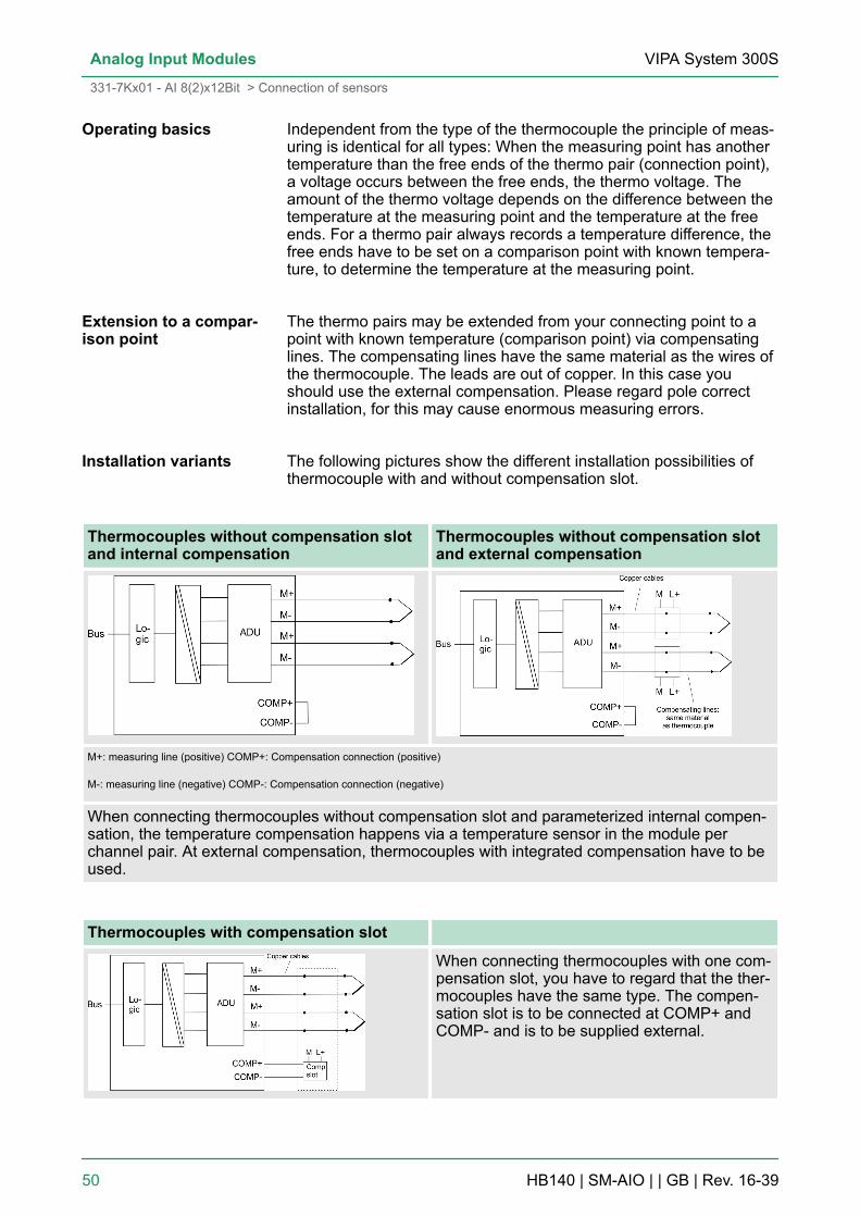
The following pictures show the different installation possibilities ofthermocouple with and without compensation slot.
Thermocouples without compensation slotand internal compensation
Thermocouples without compensation slotand external compensation
M+: measuring line (positive) COMP+: Compensation connection (positive)
M-: measuring line (negative) COMP-: Compensation connection (negative)
When connecting thermocouples without compensation slot and parameterized internal compen-sation, the temperature compensation happens via a temperature sensor in the module perchannel pair. At external compensation, thermocouples with integrated compensation have to beused.
Thermocouples with compensation slot
When connecting thermocouples with one com-pensation slot, you have to regard that the ther-mocouples have the same type. The compen-sation slot is to be connected at COMP+ andCOMP- and is to be supplied external.
Operating basics
Extension to a compar-ison point
Installation variants
VIPA System 300SAnalog Input Modules
331-7Kx01 - AI 8(2)x12Bit > Connection of sensors
HB140 | SM-AIO | | GB | Rev. 16-39 50
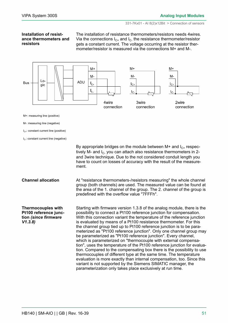
The installation of resistance thermometers/resistors needs 4wires.Via the connections IC+ and IC- the resistance thermometer/resistorgets a constant current. The voltage occurring at the resistor ther-mometer/resistor is measured via the connections M+ and M-.
M+: measuring line (positive)
M-: measuring line (negative)
IC+: constant current line (positive)
IC-: constant current line (negative)
By appropriate bridges on the module between M+ and IC+ respec-tively M- and IC- you can attach also resistance thermometers in 2-and 3wire technique. Due to the not considered conduit length youhave to count on losses of accuracy with the result of the measure-ment.
At "resistance thermometers-/resistors measuring" the whole channelgroup (both channels) are used. The measured value can be found atthe area of the 1. channel of the group. The 2. channel of the group ispredefined with the overflow value "7FFFh".
Starting with firmware version 1.3.8 of the analog module, there is thepossibility to connect a Pt100 reference junction for compensation.With this connection variant the temperature of the reference junctionis evaluated by means of a Pt100 resistance thermometer. For thisthe channel group tied up to Pt100 reference junction is to be para-meterized as "Pt100 reference junction". Only one channel group maybe parameterized as "Pt100 reference junction". Every channel,which is parameterized on "thermocouple with external compensa-tion", uses the temperature of the Pt100 reference junction for evalua-tion. Compared to the compensating box there is the possibility to usethermocouples of different type at the same time. The temperatureevaluation is more exactly than internal compensation, too. Since thisvariant is not supported by the Siemens SIMATIC manager, theparameterization only takes place exclusively at run time.
Installation of resist-ance thermometers andresistors
Channel allocation
Thermocouples withPt100 reference junc-tion (since firmwareV1.3.8)
VIPA System 300S Analog Input Modules
331-7Kx01 - AI 8(2)x12Bit > Connection of sensors
HB140 | SM-AIO | | GB | Rev. 16-39 51

M+: measuring line (positive)
M-: measuring line (negative)
IC+: constant current line (positive)
IC-: constant current line (negative)
*) With a wire break at the Pt100 reference junction for evaluation, the 1. channel of one group shows
the value 7FFFh.
The installation of the Pt100 reference junction needs 4 wires. Byappropriate bridges on the module between M+ and IC+ respectivelyM- and IC- you also may attach Pt100 in 2- and 3wire technique. Dueto the not considered conduit length you have to count on losses ofaccuracy with the result of the measurement. Here via the connec-tions IC+ and IC- the Pt resistance thermometer gets a constant cur-rent. The voltage occurring at the Pt100 resistor thermometer ismeasured via the connections M+ and M-.
At Pt100 reference junction the whole channel group (both channels)are used. The measured value can be found at the area of the 1.channel of the group. The 2. channel of the group is predefined withthe overflow value "7FFFh". Every channel, which is parameterizedon "thermocouple with external compensation", uses this measuringvalue for evaluation even in a case of a wire break it contains thevalue 7FFFh.
The analog values are only processed by the CPU in binary represen-tation. Hereby the process signals are transformed into digital formatin the analog module and passed on to the CPU as word variable.The digitized analog value is the same for input and output values atthe same nominal range.
Connection Pt100 refer-ence junction
Channel allocation
Analog value represen-tation
VIPA System 300SAnalog Input Modules
331-7Kx01 - AI 8(2)x12Bit > Connection of sensors
HB140 | SM-AIO | | GB | Rev. 16-39 52

The resolution of an analog value is 14bit plus sign bit. Bit 15 servesas sign bit (SG) with the meaning:For the sign bit is valid:n Bit 15 = "0" ® positive valuen Bit 15 = "1" ® negative valueDepending upon parameterized interference frequency (integrationtime) the modules offers different resolutions. The not used low bytebits are set to "0".
Resolu-tion
Analog value
High-Byte (Byte 0) Low-Byte (Byte 1)
Bit number 15 14 13 12 11 10 9 8 7 6 5 4 3 2 1 0
Value SG 214 213 212 211 210 29 28 27 26 25 24 23 22 21 20
14bit+sign SG Measuring value (interference frequency 10Hz) 0
12bit+sign SG Measuring value (interference frequency 50Hz, 60Hz) 0 0 0
9bit+sign SG Measuring value (interference frequency 400Hz) 0 0 0 0 0 0
This resolution does not apply to temperature levels.The converted temperature levels are the result of aconversion of the analog module.
As soon as a measured value exceeds the overdrive region and/orfalls below the underdrive region, the following value is issued:n Measuring value > end of overdrive region: 32767(7FFFh)n Measuring value < end of underdrive region: -32768(8000h)
3.4.2 331-7Kx01 - AI 8(2)x12Bit - ParameterizationAfter power ON every channel of the modules is adjusted to ±10Vwith an interference frequency of 50Hz. The diagnostic function isdeactivated. At the parameterization, a record set of 16byte length istransferred to both modules. Here the AI 2x12Bit (331-7KB01) usesthe parameters for the channel group 0/1 the parameters for furtherchannel groups are ignored.
Parameters which are not supported by the Siemenshardware configurator may only be changed during runtime by means of SFCs.
Resolution
Behavior at over- andunderflow
Overview
VIPA System 300S Analog Input Modules
331-7Kx01 - AI 8(2)x12Bit > 331-7Kx01 - AI 8(2)x12Bit - Parameterization
HB140 | SM-AIO | | GB | Rev. 16-39 53

1. Start the hardware configurator and load your project for theanalog module.
2. Open the hardware catalog to install the analog input module. Inthe hardware catalog the analog modules with the order-no.:6ES7 331-7KB01 (2x12Bit) and 6ES7 331-7KF01 (8x12Bit) canbe found at SIMATIC 300/SM-300/AI-300.
3. Choose the according module and drag & drop this module tothe concerning slot in the hardware configurator.
Via double click on the wanted module in the hardware configuratoryou open the concerning parameter window. You can change the fol-lowing module parameters:n Starting address for CPU mappingn Measuring ranges, measuring type and integration times for
channel pairsn Process interrupt at limit value overflow for channel 0 and channel
2n Limit value action at overflown Diagnosis and group diagnosis for each channel pair at wire break
or measuring range over-/underflow.
1. Save and translate your project.2. Switch your CPU in STOP.3. Transfer your project into the CPU.4. As soon as you switch the CPU into RUN, the parameters are
transmitted to the analog input module.
More information about the parameters can be found at the followingpages.
3.4.2.1 Structure of the parameter bytes Record set 0, Record set 1At the parameterization, a parameter area of 16byte length is storedin the record sets 0 and 1. Here the data irrelevant for the module AI2x12Bit (331-7KB01) are ignored. Using the SFCs 55, 56 and 57 youcan only change parameters at record set 1 and transfer during run-time to the analog module. On this way parameters may be trans-ferred which are not supported by the Siemens SIMATIC manager, ase.g. setting of high temperature measuring ranges.
Install module
Parameterize themodule
Save and transfer yourproject
Parameter Record set 0(not parameterizable viaSFC)
VIPA System 300SAnalog Input Modules
331-7Kx01 - AI 8(2)x12Bit > 331-7Kx01 - AI 8(2)x12Bit - Parameterization
HB140 | SM-AIO | | GB | Rev. 16-39 54

Record set 0 (Byte 0 to 1):
Byte Bit 7 ... Bit 0 Default
0 Group diagnosis bit codedn Bit 0: Channel 0/1n Bit 1: Channel 2/3n Bit 2: Channel 4/5n Bit 3: Channel 6/7n Bit 7 ... 4: reserved
00h
1 Wire break test bit codedn Bit 0: Channel 0/1n Bit 1: Channel 2/3n Bit 2: Channel 4/5n Bit 3: Channel 6/7n Bit 7 ... 4: reserved
00h
Record set 1 (Byte 0 to 13):
Byte Bit 7 ... Bit 0 Default
0 n Bit 5 ... 0: reservedn Bit 6: Diagnostic interrupt releasen Bit 7: Process interrupt release
00h
1 Interference frequency suppressionn Bit 0, 1: Channel 0/1n Bit 2, 3: Channel 2/3n Bit 4, 5: Channel 4/5n Bit 6, 7: Channel 6/7
Values:n 00: 400Hz (2.5ms)n 01: 60Hz (16.6ms)n 10: 50Hz (20ms)n 11: 10Hz (100ms)
AAh
2 Mode Channel 0/1n Bit 3 ... 0: Measuring rangen Bit 7 ... 4: Measuring type
19h(+/-10V)
3 Mode Channel 2/3n Bit 3 ... 0: Measuring rangen Bit 7 ... 4: Measuring type
19h(+/-10V)
4 Mode Channel 4/5n Bit 3 ... 0: Measuring rangen Bit 7 ... 4: Measuring type
19h(+/-10V)
5 Mode Channel 6/7n Bit 3 ... 0: Measuring rangen Bit 7 ... 4: Measuring type
19h(+/-10V)
6, 7 Upper limit value Channel 0 7FFFh
Parameter Record set 1(parameterizable viaSFC)
VIPA System 300S Analog Input Modules
331-7Kx01 - AI 8(2)x12Bit > 331-7Kx01 - AI 8(2)x12Bit - Parameterization
HB140 | SM-AIO | | GB | Rev. 16-39 55

Byte Bit 7 ... Bit 0 Default
8, 9 Lower limit value Channel 0 8000h
10, 11 Upper limit value Channel 2 7FFFh
12, 13 Lower limit value Channel 2 8000h
3.4.2.2 Measuring types and ranges
The following section shows an overview of all measuring types andranges plus binary coding for the parameterization.
To deactivate a channel the code 0000 0000 is used.
3.4.2.2.1 Measuring type Voltage measuring(Measuring type coding: 0001b)
Measuringrange
Range / Representation Rangecoding
+/- 80mV 94.071mV = End overdrive region (32511)- 80...80mV = Nominal range (-27648...27648)- 94.074mV = End underdrive region (-32512)
0001b
+/- 250mV 293.97mV = End overdrive region (32511)- 250...250mV = Nominal range (-27648...27648)- 293.98mV = End underdrive region (-32512)
0010b
+/- 500mV 587.94mV = End overdrive region (32511)- 500...500mV = Nominal range (-27648...27648)- 587.96mV = End underdrive region (-32512)
0011b
+/- 1V 1.175V = End overdrive region (32511)- 1...1V = Nominal range (-27648...27648)- 1.175V = End underdrive region (-32512)
0100b
Modus per channel pair
VIPA System 300SAnalog Input Modules
331-7Kx01 - AI 8(2)x12Bit > 331-7Kx01 - AI 8(2)x12Bit - Parameterization
HB140 | SM-AIO | | GB | Rev. 16-39 56
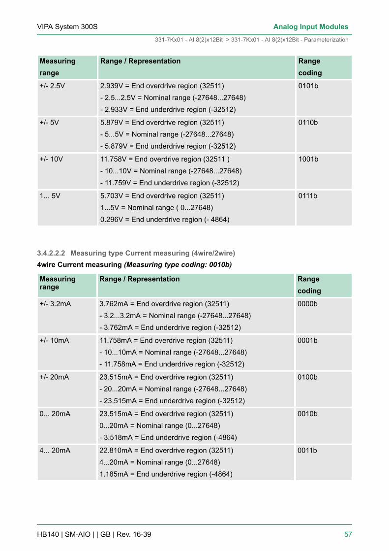
Measuringrange
Range / Representation Rangecoding
+/- 2.5V 2.939V = End overdrive region (32511)- 2.5...2.5V = Nominal range (-27648...27648)- 2.933V = End underdrive region (-32512)
0101b
+/- 5V 5.879V = End overdrive region (32511)- 5...5V = Nominal range (-27648...27648)- 5.879V = End underdrive region (-32512)
0110b
+/- 10V 11.758V = End overdrive region (32511 )- 10...10V = Nominal range (-27648...27648)- 11.759V = End underdrive region (-32512)
1001b
1... 5V 5.703V = End overdrive region (32511)1...5V = Nominal range ( 0...27648)0.296V = End underdrive region (- 4864)
0111b
3.4.2.2.2 Measuring type Current measuring (4wire/2wire)4wire Current measuring (Measuring type coding: 0010b)
Measuringrange
Range / Representation Rangecoding
+/- 3.2mA 3.762mA = End overdrive region (32511)- 3.2...3.2mA = Nominal range (-27648...27648)- 3.762mA = End underdrive region (-32512)
0000b
+/- 10mA 11.758mA = End overdrive region (32511)- 10...10mA = Nominal range (-27648...27648)- 11.758mA = End underdrive region (-32512)
0001b
+/- 20mA 23.515mA = End overdrive region (32511)- 20...20mA = Nominal range (-27648...27648)- 23.515mA = End underdrive region (-32512)
0100b
0... 20mA 23.515mA = End overdrive region (32511)0...20mA = Nominal range (0...27648)- 3.518mA = End underdrive region (-4864)
0010b
4... 20mA 22.810mA = End overdrive region (32511)4...20mA = Nominal range (0...27648)1.185mA = End underdrive region (-4864)
0011b
VIPA System 300S Analog Input Modules
331-7Kx01 - AI 8(2)x12Bit > 331-7Kx01 - AI 8(2)x12Bit - Parameterization
HB140 | SM-AIO | | GB | Rev. 16-39 57
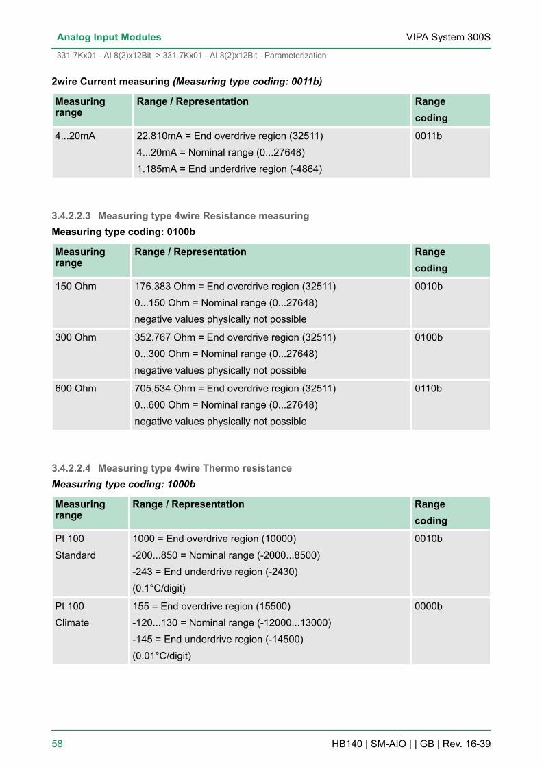
2wire Current measuring (Measuring type coding: 0011b)
Measuringrange
Range / Representation Rangecoding
4...20mA 22.810mA = End overdrive region (32511)4...20mA = Nominal range (0...27648)1.185mA = End underdrive region (-4864)
0011b
3.4.2.2.3 Measuring type 4wire Resistance measuringMeasuring type coding: 0100b
Measuringrange
Range / Representation Rangecoding
150 Ohm 176.383 Ohm = End overdrive region (32511)0...150 Ohm = Nominal range (0...27648)negative values physically not possible
0010b
300 Ohm 352.767 Ohm = End overdrive region (32511)0...300 Ohm = Nominal range (0...27648)negative values physically not possible
0100b
600 Ohm 705.534 Ohm = End overdrive region (32511)0...600 Ohm = Nominal range (0...27648)negative values physically not possible
0110b
3.4.2.2.4 Measuring type 4wire Thermo resistanceMeasuring type coding: 1000b
Measuringrange
Range / Representation Rangecoding
Pt 100Standard
1000 = End overdrive region (10000)-200...850 = Nominal range (-2000...8500)-243 = End underdrive region (-2430)(0.1°C/digit)
0010b
Pt 100Climate
155 = End overdrive region (15500)-120...130 = Nominal range (-12000...13000)-145 = End underdrive region (-14500)(0.01°C/digit)
0000b
VIPA System 300SAnalog Input Modules
331-7Kx01 - AI 8(2)x12Bit > 331-7Kx01 - AI 8(2)x12Bit - Parameterization
HB140 | SM-AIO | | GB | Rev. 16-39 58
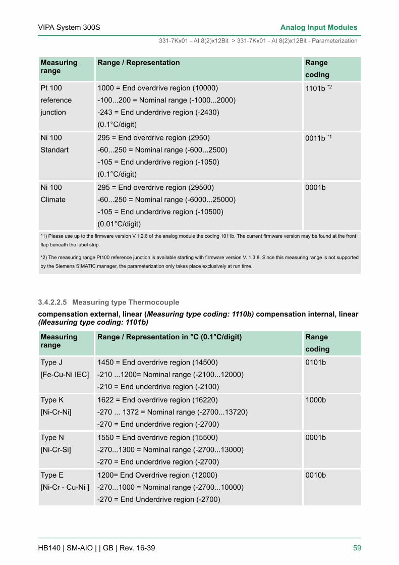
Measuringrange
Range / Representation Rangecoding
Pt 100referencejunction
1000 = End overdrive region (10000)-100...200 = Nominal range (-1000...2000)-243 = End underdrive region (-2430)(0.1°C/digit)
1101b *2
Ni 100Standart
295 = End overdrive region (2950)-60...250 = Nominal range (-600...2500)-105 = End underdrive region (-1050)(0.1°C/digit)
0011b *1
Ni 100Climate
295 = End overdrive region (29500)-60...250 = Nominal range (-6000...25000)-105 = End underdrive region (-10500)(0.01°C/digit)
0001b
*1) Please use up to the firmware version V.1.2.6 of the analog module the coding 1011b. The current firmware version may be found at the front
flap beneath the label strip.
*2) The measuring range Pt100 reference junction is available starting with firmware version V. 1.3.8. Since this measuring range is not supported
by the Siemens SIMATIC manager, the parameterization only takes place exclusively at run time.
3.4.2.2.5 Measuring type Thermocouplecompensation external, linear (Measuring type coding: 1110b) compensation internal, linear(Measuring type coding: 1101b)
Measuringrange
Range / Representation in °C (0.1°C/digit) Rangecoding
Type J[Fe-Cu-Ni IEC]
1450 = End overdrive region (14500)-210 ...1200= Nominal range (-2100...12000)-210 = End underdrive region (-2100)
0101b
Type K[Ni-Cr-Ni]
1622 = End overdrive region (16220)-270 ... 1372 = Nominal range (-2700...13720)-270 = End underdrive region (-2700)
1000b
Type N[Ni-Cr-Si]
1550 = End overdrive region (15500)-270...1300 = Nominal range (-2700...13000)-270 = End underdrive region (-2700)
0001b
Type E[Ni-Cr - Cu-Ni ]
1200= End Overdrive region (12000)-270...1000 = Nominal range (-2700...10000)-270 = End Underdrive region (-2700)
0010b
VIPA System 300S Analog Input Modules
331-7Kx01 - AI 8(2)x12Bit > 331-7Kx01 - AI 8(2)x12Bit - Parameterization
HB140 | SM-AIO | | GB | Rev. 16-39 59
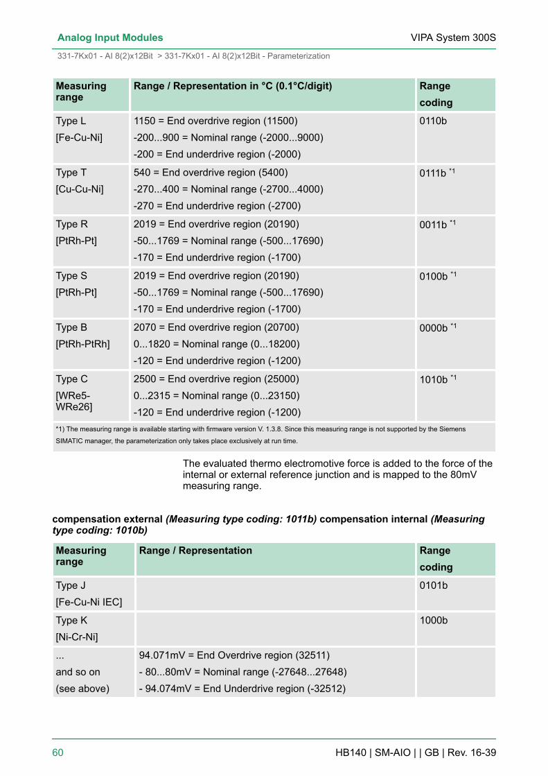
Measuringrange
Range / Representation in °C (0.1°C/digit) Rangecoding
Type L[Fe-Cu-Ni]
1150 = End overdrive region (11500)-200...900 = Nominal range (-2000...9000)-200 = End underdrive region (-2000)
0110b
Type T[Cu-Cu-Ni]
540 = End overdrive region (5400)-270...400 = Nominal range (-2700...4000)-270 = End underdrive region (-2700)
0111b *1
Type R[PtRh-Pt]
2019 = End overdrive region (20190)-50...1769 = Nominal range (-500...17690)-170 = End underdrive region (-1700)
0011b *1
Type S[PtRh-Pt]
2019 = End overdrive region (20190)-50...1769 = Nominal range (-500...17690)-170 = End underdrive region (-1700)
0100b *1
Type B[PtRh-PtRh]
2070 = End overdrive region (20700)0...1820 = Nominal range (0...18200)-120 = End underdrive region (-1200)
0000b *1
Type C[WRe5-WRe26]
2500 = End overdrive region (25000)0...2315 = Nominal range (0...23150)-120 = End underdrive region (-1200)
1010b *1
*1) The measuring range is available starting with firmware version V. 1.3.8. Since this measuring range is not supported by the Siemens
SIMATIC manager, the parameterization only takes place exclusively at run time.
The evaluated thermo electromotive force is added to the force of theinternal or external reference junction and is mapped to the 80mVmeasuring range.
compensation external (Measuring type coding: 1011b) compensation internal (Measuringtype coding: 1010b)
Measuringrange
Range / Representation Rangecoding
Type J[Fe-Cu-Ni IEC]
0101b
Type K[Ni-Cr-Ni]
1000b
...and so on(see above)
94.071mV = End Overdrive region (32511)- 80...80mV = Nominal range (-27648...27648)- 94.074mV = End Underdrive region (-32512)
VIPA System 300SAnalog Input Modules
331-7Kx01 - AI 8(2)x12Bit > 331-7Kx01 - AI 8(2)x12Bit - Parameterization
HB140 | SM-AIO | | GB | Rev. 16-39 60
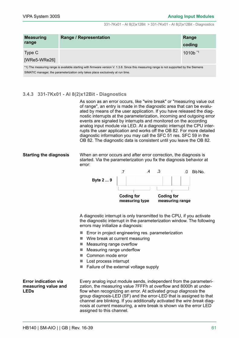
Measuringrange
Range / Representation Rangecoding
Type C[WRe5-WRe26]
1010b *1
*1) The measuring range is available starting with firmware version V. 1.3.8. Since this measuring range is not supported by the Siemens
SIMATIC manager, the parameterization only takes place exclusively at run time.
3.4.3 331-7Kx01 - AI 8(2)x12Bit - DiagnosticsAs soon as an error occurs, like "wire break" or "measuring value outof range", an entry is made in the diagnostic area that can be evalu-ated by means of the user application. If you have released the diag-nostic interrupts at the parameterization, incoming and outgoing errorevents are signaled by interrupts and monitored on the accordinganalog input module via LED. At a diagnostic interrupt the CPU inter-rupts the user application and works off the OB 82. For more detaileddiagnostic information you may call the SFC 51 res. SFC 59 in theOB 82. The diagnostic data is consistent until you leave the OB 82.
When an error occurs and after error correction, the diagnosis isstarted. Via the parameterization you fix the diagnosis behavior aterror:
A diagnostic interrupt is only transmitted to the CPU, if you activatethe diagnostic interrupt in the parameterization window. The followingerrors may initialize a diagnosis:n Error in project engineering res. parameterizationn Wire break at current measuringn Measuring range overflown Measuring range underflown Common mode errorn Lost process interruptn Failure of the external voltage supply
Every analog input module sends, independent from the parameteri-zation, the measuring value 7FFFh at overflow and 8000h at under-flow when recognizing an error. At activated group diagnosis thegroup diagnosis-LED (SF) and the error-LED that is assigned to thatchannel are blinking. If you additionally activated the wire break diag-nosis at current measuring, a wire break is shown via the error LEDassigned to this channel.
Starting the diagnosis
Error indication viameasuring value andLEDs
VIPA System 300S Analog Input Modules
331-7Kx01 - AI 8(2)x12Bit > 331-7Kx01 - AI 8(2)x12Bit - Diagnostics
HB140 | SM-AIO | | GB | Rev. 16-39 61

At a diagnosis event the CPU interrupts the user program andbranches into OB 82. This OB allows you via according programmingto request detailed diagnostic information by means of the SFCs 51and 59 and react to it. After processing of the OB 82, the processingof the user application is continued. The diagnostic data are consis-tent until leaving the OB 82. As soon as you have activated the diag-nostic interrupt release, record set 0 is transferred to the superordi-nated system in cause of an error. The record set 0 has a fixedcontent and a length of 4byte. The content of record set 0 may bemonitored in plain text in the diagnosis window of the CPU. For theextended diagnosis during run time, you may also evaluate the recordset 1 of 16byte length via SFCs 51 and 59. Record set 0 and 1 havethe following structure:
Record set 0 (Byte 0 to 3):
Byte Bit 7 ... Bit 0 Default
0 n Bit 0: Error in modulen Bit 1: reservedn Bit 2: External errorn Bit 3: Channel errorn Bit 4: external voltage supply missingn Bit 6, 5: reservedn Bit 7: Wrong parameters in module
00h
1 n Bit 3 ... 0: Module class– 0101b Analog module
n Bit 4: Channel information presentn Bit 7 ... 5: reserved
15h
2 reserved 00h
3 n Bit 5 ... 0: reservedn Bit 6: Process interrupt lostn Bit 7: reserved
00h
Byte 0 to 15:The record set 1 contains the 4byte of record set 0 and additionally12byte module specific diagnostic data. The diagnostic bytes havethe following assignment:
Evaluating the diag-nosis
Diagnosis record set 0
Diagnosis record set 1
VIPA System 300SAnalog Input Modules
331-7Kx01 - AI 8(2)x12Bit > 331-7Kx01 - AI 8(2)x12Bit - Diagnostics
HB140 | SM-AIO | | GB | Rev. 16-39 62

Record set 1 (Byte 0 to 15):
Byte Bit 7 ... Bit 0 Default
0 ... 3 Content record set 0(see page before)
-
4 n Bit 6 ... 0: Channel type– 70h: Digital input– 71h: Analog input– 72h: Digital output– 73h: Analog output– 74h: Analog in-/output
n Bit 7: More channel types present– 0: no– 1: yes
71h
5 n Number of diagnostic bits,that the module throws per channel
08h
6 n Bit 7 ... 0: Number of similar channels of amodule
04h
7 n Bit 0: Channel error Channel 0n ...n Bit 7: Channel error Channel 7
00h
8 n Bit 0: Project engineering/Parameterizationerror Channel 0
n Bit 1: Common mode errorn Bit 3 ... 2: reservedn Bit 4: Wire break Channel 0n Bit 5: reservedn Bit 6: Underflow Channel 0n Bit 7: Overflow Channel 0
00h
... ...
15 n Bit 0: Project engineering/Parameterizationerror Channel 7
n Bit 1: Common mode errorn Bit 3 ... 2: reservedn Bit 4: Wire break Channel 7n Bit 5: reservedn Bit 6: Underflow Channel 7n Bit 7: Overflow Channel 7
00h
Please note that the AI 2x12Bit (331-7KB01) exclu-sively supplies diagnostic data of the channel group0/1!
Error cause and remedy
VIPA System 300S Analog Input Modules
331-7Kx01 - AI 8(2)x12Bit > 331-7Kx01 - AI 8(2)x12Bit - Diagnostics
HB140 | SM-AIO | | GB | Rev. 16-39 63
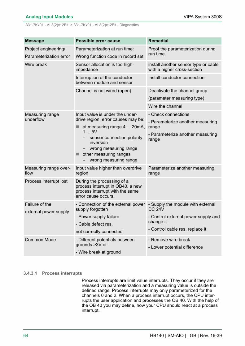
Message Possible error cause Remedial
Project engineering/Parameterization error
Parameterization at run time:Wrong function code in record set
Proof the parameterization duringrun time
Wire break Sensor allocation is too high-impedance
install another sensor type or cablewith a higher cross-section
Interruption of the conductorbetween module and sensor
Install conductor connection
Channel is not wired (open) Deactivate the channel group(parameter measuring type)
Wire the channel
Measuring rangeunderflow
Input value is under the under-drive region, error causes may be:n at measuring range 4 ... 20mA,
1 ... 5V– sensor connection polarity
inversion– wrong measuring range
n other measuring ranges– wrong measuring range
- Check connections- Parameterize another measuringrange- Parameterize another measuringrange
Measuring range over-flow
Input value higher than overdriveregion
Parameterize another measuringrange
Process interrupt lost During the processing of aprocess interrupt in OB40, a newprocess interrupt with the sameerror cause occurs.
Failure of theexternal power supply
- Connection of the external powersupply forgotten- Power supply failure- Cable defect res.not correctly connected
- Supply the module with externalDC 24V- Control external power supply andchange it- Control cable res. replace it
Common Mode - Different potentials betweengrounds >3V or- Wire break at ground
- Remove wire break- Lower potential difference
3.4.3.1 Process interruptsProcess interrupts are limit value interrupts. They occur if they arereleased via parameterization and a measuring value is outside thedefined range. Process interrupts may only parameterized for thechannels 0 and 2. When a process interrupt occurs, the CPU inter-rupts the user application and processes the OB 40. With the help ofthe OB 40 you may define, how your CPU should react at a processinterrupt.
VIPA System 300SAnalog Input Modules
331-7Kx01 - AI 8(2)x12Bit > 331-7Kx01 - AI 8(2)x12Bit - Diagnostics
HB140 | SM-AIO | | GB | Rev. 16-39 64

As soon as a measuring value is out of the range defined in theparameterization, a processes interrupt is initialized, if this option isreleased. Via the parameterization you define the part of the nominalrange, in which the value has to be, by means of defining high andlow limit. A process interrupt may only be initialized, when you haveactivated hardware interrupt when limit exceeded.
You may activate a process interrupt for channel 0 and 2. Using thedefault configuration, the process interrupts are not activated.
At a process interrupt the CPU interrupts the user application andbranches into the OB 40. More detailed information about thechannel, which limit value has been exceeded, are stored in the OB40 in the variable OB 40_POINT_ADR in the local data double word 8(LD 8).
The LD 8 has the following structure:
Byte Bit 7... Bit 0
0 n Bit: 0 = 1: Upper limit value of channel 0has been exceeded
n Bit: 1 = 1: Upper limit value of channel 2has been exceeded
1 n Bit: 0 = 1: Lower limit value of channel 0 has beenexceeded
n Bit: 1 = 1: Lower limit value of channel 2 has beenexceeded
2 ... 3 reserved
Initializing the processinterrupt
Reaction to the processinterrupt
VIPA System 300S Analog Input Modules
331-7Kx01 - AI 8(2)x12Bit > 331-7Kx01 - AI 8(2)x12Bit - Diagnostics
HB140 | SM-AIO | | GB | Rev. 16-39 65

If a second identical process interrupt occurs during processing inter-rupt in OB 40, the CPU branches into the OB 82 and activates the bit6 in record set 0 of byte 3 for "process interrupt lost". After havingprocessed the OB 82, the CPU jumps back to OB 40.
The behavior of the analog input module depends on the location ofthe measuring value inside the value range. The following table liststhe different behavior:
Measuring valueis in
transmitted SF-LED *4 Diagnostics Interrupt
Nominal range meas. value - - -
Over-/Underdrive region
meas. value - - -
Overflow 7FFFh ON *3 Entry is set *3 Diag. interrupt *1
Underflow 8000h ON *3 Entry is set *3 Diag. interrupt *1
outside the para-meterized limitvalue
meas. value - - Process
interrupt *2
*1) only if diagnostic interrupt is released in the parameterization.
*2) only if process interrupt is released in the parameterization.
*3) only if group diagnostics is released in the parameterization.
*4) independently from the chosen diagnostics, the group error LED is on when the external power supply is missing.
3.4.4 331-7KB01 - Technical data
Order no. 331-7KB01
Type SM 331
SPEED-Bus -
Current consumption/power loss
Current consumption from backplane bus 95 mA
Power loss 3 W
Technical data analog inputs
Number of inputs 2
Cable length, shielded 50 m
Rated load voltage DC 24 V
Current consumption from load voltage L+(without load)
100 mA
Voltage inputs ü
Diagnostic message"Process interrupt lost"
Influence of the meas-uring values
VIPA System 300SAnalog Input Modules
331-7Kx01 - AI 8(2)x12Bit > 331-7KB01 - Technical data
HB140 | SM-AIO | | GB | Rev. 16-39 66

Order no. 331-7KB01
Min. input resistance (voltage range) 100 kΩ
Input voltage ranges -80 mV ... +80 mV-250 mV ... +250 mV-500 mV ... +500 mV-1 V ... +1 V-2.5 V ... +2.5 V-5 V ... +5 V+1 V ... +5 V-10 V ... +10 V
Operational limit of voltage ranges +/-0.6% ... +/-1.0%
Operational limit of voltage ranges with SFU -
Basic error limit voltage ranges +/-0.4% ... +/-0.7%
Basic error limit voltage ranges with SFU -
Destruction limit voltage max. 15V
Current inputs ü
Max. input resistance (current range) 85 Ω
Input current ranges -3.2 mA ... +3.2 mA-10 mA ... +10 mA-20 mA ... +20 mA0 mA ... +20 mA+4 mA ... +20 mA
Operational limit of current ranges +/-0.7%
Operational limit of current ranges with SFU -
Grundfehlergrenze Strombereiche +/-0.5%
Radical error limit current ranges with SFU -
Destruction limit current inputs (electrical cur-rent)
max. 40mA
Destruction limit current inputs (voltage) max. 15V
Resistance inputs ü
Resistance ranges 0 ... 150 Ohm0 ... 300 Ohm0 ... 600 Ohm
Operational limit of resistor ranges +/-0.7%
Operational limit of resistor ranges with SFU -
Basic error limit +/-0.5%
VIPA System 300S Analog Input Modules
331-7Kx01 - AI 8(2)x12Bit > 331-7KB01 - Technical data
HB140 | SM-AIO | | GB | Rev. 16-39 67

Order no. 331-7KB01
Basic error limit with SFU -
Destruction limit resistance inputs max. 15V
Resistance thermometer inputs ü
Resistance thermometer ranges Pt100Ni100
Operational limit of resistance thermometerranges
+/-0.7% ... +/-0.8%
Operational limit of resistance thermometerranges with SFU
-
Basic error limit thermoresistor ranges +/-0.5% ... +/-0.6%
Basic error limit thermoresistor ranges withSFU
-
Destruction limit resistance thermometer inputs max. 15V
Thermocouple inputs ü
Thermocouple ranges type Jtype Rtype Ktype Ntype Ltype Etype Ttype Stype Btype C
Operational limit of thermocouple ranges +/-1.3% ... +/-2.0%
Operational limit of thermocouple ranges withSFU
-
Basic error limit thermoelement ranges +/-0.7% ... +/-1.0%
Basic error limit thermoelement ranges withSFU
-
Destruction limit thermocouple inputs max. 15V
Programmable temperature compensation ü
External temperature compensation ü
Internal temperature compensation ü
Temperature error internal compensation 3 K
Technical unit of temperature measurement °C
Resolution in bit 14
VIPA System 300SAnalog Input Modules
331-7Kx01 - AI 8(2)x12Bit > 331-7KB01 - Technical data
HB140 | SM-AIO | | GB | Rev. 16-39 68
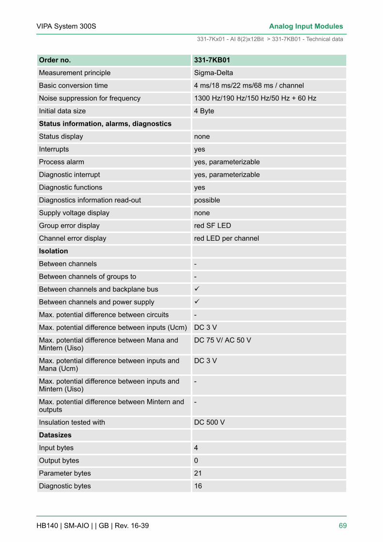
Order no. 331-7KB01
Measurement principle Sigma-Delta
Basic conversion time 4 ms/18 ms/22 ms/68 ms / channel
Noise suppression for frequency 1300 Hz/190 Hz/150 Hz/50 Hz + 60 Hz
Initial data size 4 Byte
Status information, alarms, diagnostics
Status display none
Interrupts yes
Process alarm yes, parameterizable
Diagnostic interrupt yes, parameterizable
Diagnostic functions yes
Diagnostics information read-out possible
Supply voltage display none
Group error display red SF LED
Channel error display red LED per channel
Isolation
Between channels -
Between channels of groups to -
Between channels and backplane bus ü
Between channels and power supply ü
Max. potential difference between circuits -
Max. potential difference between inputs (Ucm) DC 3 V
Max. potential difference between Mana andMintern (Uiso)
DC 75 V/ AC 50 V
Max. potential difference between inputs andMana (Ucm)
DC 3 V
Max. potential difference between inputs andMintern (Uiso)
-
Max. potential difference between Mintern andoutputs
-
Insulation tested with DC 500 V
Datasizes
Input bytes 4
Output bytes 0
Parameter bytes 21
Diagnostic bytes 16
VIPA System 300S Analog Input Modules
331-7Kx01 - AI 8(2)x12Bit > 331-7KB01 - Technical data
HB140 | SM-AIO | | GB | Rev. 16-39 69

Order no. 331-7KB01
Housing
Material PPE
Mounting Rail System 300
Mechanical data
Dimensions (WxHxD) 40 mm x 125 mm x 120 mm
Weight 220 g
Environmental conditions
Operating temperature 0 °C to 60 °C
Storage temperature -25 °C to 70 °C
Certifications
UL certification yes
KC certification yes
Additional Technical data
Order number 331-7KB01
Data for specific module
Number of inputs for 4wire resistance-typesensor
1
Voltages, Currents, Potentials
Power supply of the transmitters
- Supply voltage 13V at 30mA
- Supply current max. 30mA (per channel)
- Short-circuit-proof yes
Constant current for resistance-type sensor 2.25mA
Analog value generation
Integration - /conversion time/resolution (perchannel)
- programmable yes
- Conversion rate in Hz 400 60 50 10
- Integration time in ms 2.5 162/3 20 100
- Basic conversion time in ms 4 18 22 68
Additional conversion time for open circuitmonitoring in ms
4ms
- Resolution (incl. overrange) in Bit 9 12 12 14
- Noise suppression for frequency f1 in Hz - - - 50/60
VIPA System 300SAnalog Input Modules
331-7Kx01 - AI 8(2)x12Bit > 331-7KB01 - Technical data
HB140 | SM-AIO | | GB | Rev. 16-39 70

Order number 331-7KB01
- Basic execution time of the module in ms (allchannels enabled)
18 46 54 146
Smoothing of the measured values none
Suppression of interference, limits error
Noises suppression for f=n x (f1 ±1%)(f1=interference frequency, n=1, 2,...)
- Common-mode interference (UCM < 3V) > 70dB
- Series-mode noise (peak value of noise <nominal value of input range
> 40dB
Crosstalk between the inputs > 50dB
Temperature error (with reference to the inputrange)
±0.005%/K
Linearity error (with reference to the inputrange)
±0.02%
Repeatability (in steady state at 25°C, with ref-erence to the input range)
±0.05%
Temperature error of internal compensation ±1.5%
Data for selecting a sensor
Input resistance
- Voltage
± 80mV, ± 250mV 10MW
± 500mV, ± 1V 10MW
± 2,5V, ± 5V 100kW
1 ... 5V, ± 10V 100kW
- Current
± 3,2mA, ± 10mA, ± 20mA 85W
0 ... 20mA, 4 ... 20mA 85W
- Resistance
0 ... 150W, 300W, 600W 10MW
- Resistance thermometer
Pt100, NI100 10MW
- Thermocouples
Type J, K, N, L, E, T, S, B, C, R 10MW
Maximum input voltage for voltage input(destruction limit)
max. 20V
Maximum input current for current input(destruction limit)
max. 40mA
VIPA System 300S Analog Input Modules
331-7Kx01 - AI 8(2)x12Bit > 331-7KB01 - Technical data
HB140 | SM-AIO | | GB | Rev. 16-39 71

Order number 331-7KB01
Connection of the sensors
- for measuring voltage possible
- for measuring current
as 2wire transmitter possible
as 4wire transmitter possible
- for measuring resistance
with 2conductor connection possible
with 3conductor connection possible
with 4conductor connection possible
Characteristic linearization
- for RTD Pt100, NI 100 Standard / Climate
- for thermocouples Type E, N, J, K, L, T, S, B, C, R, Ni100Standard / Climate
Temperature compensation parameterizable
- internal temperature compensation possible
- external temperature compensation with com-pensating box
possible
- Compensation for 0°C comparison point tem-perature
possible
Technical unit for temperature measurement °C
The thermocouples for high temperature measurement (Type S, B, C,R) produce physically caused smaller thermo electromotive forcesthan the "normal" thermocouples (Type E, N, J, K, L). In the followingtable there is a comparison between the thermo electromotive forcesof the thermocouple of the type N to type S, B, C, R.
Thermo electromotive forcesof Thermocouples
0°C 500°C 1000°C 1700°C
Type N in µV / °C 26 38 39 not possible
Type S in µV / °C 5 10 12 12
Type B in µV / °C 0 5 9 11
Type C in µV / °C 13 19 18 14
Type R in µV / °C 5 11 13 13
Thermocouple for hightemperature measure-ment
VIPA System 300SAnalog Input Modules
331-7Kx01 - AI 8(2)x12Bit > 331-7KB01 - Technical data
HB140 | SM-AIO | | GB | Rev. 16-39 72

3.4.5 331-7KF01 - Technical data
Order no. 331-7KF01
Type SM 331
SPEED-Bus -
Current consumption/power loss
Current consumption from backplane bus 95 mA
Power loss 3 W
Technical data analog inputs
Number of inputs 8
Cable length, shielded 50 m
Rated load voltage DC 24 V
Current consumption from load voltage L+(without load)
100 mA
Voltage inputs ü
Min. input resistance (voltage range) 100 kΩ
Input voltage ranges -80 mV ... +80 mV-250 mV ... +250 mV-500 mV ... +500 mV-1 V ... +1 V-2.5 V ... +2.5 V-5 V ... +5 V+1 V ... +5 V-10 V ... +10 V
Operational limit of voltage ranges +/-0.6% ... +/-1.0%
Operational limit of voltage ranges with SFU -
Basic error limit voltage ranges +/-0.4% ... +/-0.7%
Basic error limit voltage ranges with SFU -
Destruction limit voltage max. 15V
Current inputs ü
Max. input resistance (current range) 85 Ω
Input current ranges -3.2 mA ... +3.2 mA-10 mA ... +10 mA-20 mA ... +20 mA0 mA ... +20 mA+4 mA ... +20 mA
Operational limit of current ranges +/-0.7%
VIPA System 300S Analog Input Modules
331-7Kx01 - AI 8(2)x12Bit > 331-7KF01 - Technical data
HB140 | SM-AIO | | GB | Rev. 16-39 73

Order no. 331-7KF01
Operational limit of current ranges with SFU -
Grundfehlergrenze Strombereiche +/-0.5%
Radical error limit current ranges with SFU -
Destruction limit current inputs (electrical cur-rent)
max. 40mA
Destruction limit current inputs (voltage) max. 15V
Resistance inputs ü
Resistance ranges 0 ... 150 Ohm0 ... 300 Ohm0 ... 600 Ohm
Operational limit of resistor ranges +/-0.7%
Operational limit of resistor ranges with SFU -
Basic error limit +/-0.5%
Basic error limit with SFU -
Destruction limit resistance inputs max. 15V
Resistance thermometer inputs ü
Resistance thermometer ranges Pt100Ni100
Operational limit of resistance thermometerranges
+/-0.7% ... +/-0.8%
Operational limit of resistance thermometerranges with SFU
-
Basic error limit thermoresistor ranges +/-0.5% ... +/-0.6%
Basic error limit thermoresistor ranges withSFU
-
Destruction limit resistance thermometer inputs max. 15V
Thermocouple inputs ü
VIPA System 300SAnalog Input Modules
331-7Kx01 - AI 8(2)x12Bit > 331-7KF01 - Technical data
HB140 | SM-AIO | | GB | Rev. 16-39 74
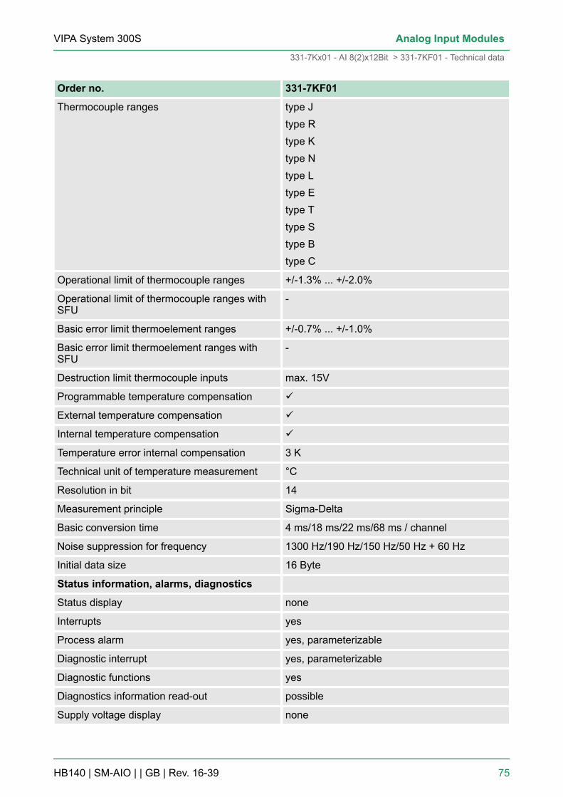
Order no. 331-7KF01
Thermocouple ranges type Jtype Rtype Ktype Ntype Ltype Etype Ttype Stype Btype C
Operational limit of thermocouple ranges +/-1.3% ... +/-2.0%
Operational limit of thermocouple ranges withSFU
-
Basic error limit thermoelement ranges +/-0.7% ... +/-1.0%
Basic error limit thermoelement ranges withSFU
-
Destruction limit thermocouple inputs max. 15V
Programmable temperature compensation ü
External temperature compensation ü
Internal temperature compensation ü
Temperature error internal compensation 3 K
Technical unit of temperature measurement °C
Resolution in bit 14
Measurement principle Sigma-Delta
Basic conversion time 4 ms/18 ms/22 ms/68 ms / channel
Noise suppression for frequency 1300 Hz/190 Hz/150 Hz/50 Hz + 60 Hz
Initial data size 16 Byte
Status information, alarms, diagnostics
Status display none
Interrupts yes
Process alarm yes, parameterizable
Diagnostic interrupt yes, parameterizable
Diagnostic functions yes
Diagnostics information read-out possible
Supply voltage display none
VIPA System 300S Analog Input Modules
331-7Kx01 - AI 8(2)x12Bit > 331-7KF01 - Technical data
HB140 | SM-AIO | | GB | Rev. 16-39 75
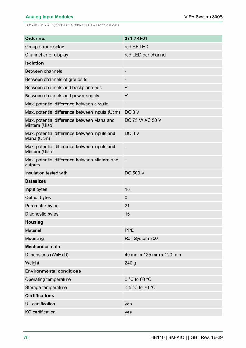
Order no. 331-7KF01
Group error display red SF LED
Channel error display red LED per channel
Isolation
Between channels -
Between channels of groups to -
Between channels and backplane bus ü
Between channels and power supply ü
Max. potential difference between circuits -
Max. potential difference between inputs (Ucm) DC 3 V
Max. potential difference between Mana andMintern (Uiso)
DC 75 V/ AC 50 V
Max. potential difference between inputs andMana (Ucm)
DC 3 V
Max. potential difference between inputs andMintern (Uiso)
-
Max. potential difference between Mintern andoutputs
-
Insulation tested with DC 500 V
Datasizes
Input bytes 16
Output bytes 0
Parameter bytes 21
Diagnostic bytes 16
Housing
Material PPE
Mounting Rail System 300
Mechanical data
Dimensions (WxHxD) 40 mm x 125 mm x 120 mm
Weight 240 g
Environmental conditions
Operating temperature 0 °C to 60 °C
Storage temperature -25 °C to 70 °C
Certifications
UL certification yes
KC certification yes
VIPA System 300SAnalog Input Modules
331-7Kx01 - AI 8(2)x12Bit > 331-7KF01 - Technical data
HB140 | SM-AIO | | GB | Rev. 16-39 76

Additional Technical data
Order number 331-7KF01
Data for specific module
Number of inputs for 4wire resistance-typesensor
4
Voltages, Currents, Potentials
Power supply of the transmitters
- Supply voltage 13V at 30mA
- Supply current max. 30mA (per channel)
- Short-circuit-proof yes
Constant current for resistance-type sensor 2.25mA
Analog value generation
Integration - /conversion time/resolution (perchannel)
- programmable yes
- Conversion rate in Hz 400 60 50 10
- Integration time in ms 2.5 162/3 20 100
- Basic conversion time in ms 4 18 22 68
Additional conversion time for open circuitmonitoring in ms
- Resolution (incl. overrange) in Bit 9 12 12 14
- Noise suppression for frequency f1 in Hz - - - 50/60
- Basic execution time of the module in ms (allchannels enabled)
42 154 186 554
Smoothing of the measured values none
Suppression of interference, limits error
Noises suppression for f=n x (f1 ±1%)(f1=interference frequency, n=1, 2,...)
- Common-mode interference (UCM < 3V) > 70dB
- Series-mode noise (peak value of noise <nominal value of input range
> 40dB
Crosstalk between the inputs > 50dB
Temperature error (with reference to the inputrange)
±0.005%/K
Linearity error (with reference to the inputrange)
±0.02%
Repeatability (in steady state at 25°C, with ref-erence to the input range)
±0.05%
VIPA System 300S Analog Input Modules
331-7Kx01 - AI 8(2)x12Bit > 331-7KF01 - Technical data
HB140 | SM-AIO | | GB | Rev. 16-39 77
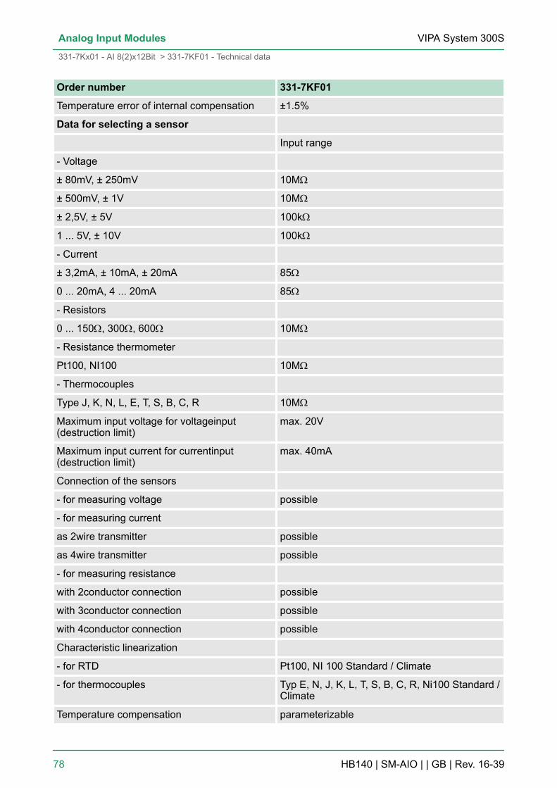
Order number 331-7KF01
Temperature error of internal compensation ±1.5%
Data for selecting a sensor
Input range
- Voltage
± 80mV, ± 250mV 10MW
± 500mV, ± 1V 10MW
± 2,5V, ± 5V 100kW
1 ... 5V, ± 10V 100kW
- Current
± 3,2mA, ± 10mA, ± 20mA 85W
0 ... 20mA, 4 ... 20mA 85W
- Resistors
0 ... 150W, 300W, 600W 10MW
- Resistance thermometer
Pt100, NI100 10MW
- Thermocouples
Type J, K, N, L, E, T, S, B, C, R 10MW
Maximum input voltage for voltageinput(destruction limit)
max. 20V
Maximum input current for currentinput(destruction limit)
max. 40mA
Connection of the sensors
- for measuring voltage possible
- for measuring current
as 2wire transmitter possible
as 4wire transmitter possible
- for measuring resistance
with 2conductor connection possible
with 3conductor connection possible
with 4conductor connection possible
Characteristic linearization
- for RTD Pt100, NI 100 Standard / Climate
- for thermocouples Typ E, N, J, K, L, T, S, B, C, R, Ni100 Standard /Climate
Temperature compensation parameterizable
VIPA System 300SAnalog Input Modules
331-7Kx01 - AI 8(2)x12Bit > 331-7KF01 - Technical data
HB140 | SM-AIO | | GB | Rev. 16-39 78

Order number 331-7KF01
- internal temperature compensation possible
- external temperature compensation with com-pensating box
possible
- Compensation for 0°C comparison point tem-perature
possible
Technical unit for temperature measurement °C
The thermocouples for high temperature measurement (Type S, B, C,R) produce physically caused smaller thermo electromotive forcesthan the "normal" thermocouples (Type E, N, J, K, L). In the followingtable there is a comparison between the thermo electromotive forcesof the thermocouple of the type N to type S, B, C, R.
Thermo electromotive forcesof Thermocouples
0°C 500°C 1000°C 1700°C
Type N in µV / °C 26 38 39 not possible
Type S in µV / °C 5 10 12 12
Type B in µV / °C 0 5 9 11
Type C in µV / °C 13 19 18 14
Type R in µV / °C 5 11 13 13
Thermocouple for hightemperature measure-ment
VIPA System 300S Analog Input Modules
331-7Kx01 - AI 8(2)x12Bit > 331-7KF01 - Technical data
HB140 | SM-AIO | | GB | Rev. 16-39 79

4 Analog Output Modules4.1 General
For analog signals you should use isolated cables to reduce interfer-ence. The cable screening should be grounded at both ends. If thereare differences in the potential between the cable ends, there mayoccur a potential compensating current that could disturb the analogsignals. In this case you should ground the cable screening only atone end.
Depending on the module the following actuators may be connected:n Current input: ±20mA, 4 ... 20mA, 0 ... 20mAn Voltage input: ±10V, 1 ... 5V, 0 ... 10V
Please take always care of the correct polarity whenconnecting actuators! Please leave the output pins ofnot used channels disconnected and configure theoutput type of the channel to "deactivated".
The modules can be configured by means of a hardware configura-tion or rather during run time by SFCs. In not parameterized status,the modules with order number 332-5Hx01 are set to voltage output"±10V". The interrupt output of every module is deactivated.
Every module described here has diagnostic functions. Depending onthe module the following errors may initialize a diagnostic message: Adiagnostic interrupt is only transmitted to the CPU, if you have acti-vated the diagnostic interrupt in the parameterization window. The fol-lowing errors a diagnosis:n Wire break at current output (only 332-5Hx01)n Ground short circuit (only 332-5Hx01)n Operate the front switch (only 332-5HDx0)n Failure of the external voltage supplyn Project engineering and parameterization errorFor more detailed diagnostic information you may call the SFCs 51and 59 during run time. You can request detailed diagnostic informa-tion and react on it by means of the SFCs.
System-dependently at switching on/off the power supply and atoutput range alterations during run time, there may arise wrongvalues for app. 10ms.
4.2 Connecting loads and actuatorsLoads at the current output have to be connected at QX and associ-ated ground MX of the analog circuit. Please always pay attention tocorrect polarity.
Cables for analog sig-nals
Connecting loads andactuators
Parameterization
Diagnostic functions
Output pulse at PowerON/OFF and at outputrange alterations duringrun time
Connecting loads atcurrent output
VIPA System 300SAnalog Output Modules
Connecting loads and actuators
HB140 | SM-AIO | | GB | Rev. 16-39 80

The connection of a load at a voltage output can take place both in 2-and in 4-wire cabling. Please note with the modules 332-5HDx0 the4-wire cabling is not possible. With 4-wire cabling you achieve a highexactness at the load. The sensor lines S+X and S-X are directly con-nected to the load. Thus, the voltage may be measured and adjusteddirectly at the load. Interference or voltage losses may cause poten-tial differences between S-X and MX. These should not exceed thepermissible value of DC 3V, because this may disturb the accuracy ofthe analog signal.
Connect the load at pin QVX and the point of reference of the meas-uring circle MX (x = No. of the channel).
Connecting loads atvoltage output at 4-wirecabling (only332-5Hx01)
Connecting loads atvoltage output at 2-wirecabling
VIPA System 300S Analog Output Modules
Connecting loads and actuators
HB140 | SM-AIO | | GB | Rev. 16-39 81

4.3 Analog value representationThe analog values are only processed by the CPU in binary represen-tation. Hereby the process signals are transformed into digital formatin the analog module and passed on to the CPU as word variable.The digitized analog value is the same for input and output values atthe same nominal range. The resolution depends on the used moduleas follows:
Resolu-tion
Analog value
High-Byte (Byte 0) Low-Byte (Byte 1)
Bit number 15 14 13 12 11 10 9 8 7 6 5 4 3 2 1 0
Resolution SG Analog value (word)
12bit+Sign SG Relevant output value X
11bit+Sign SG Relevant output value X X X
10bit+Sign SG Relevant output value X X X X X X
*) The least significant irrelevant bits of the output value are marked by "X".
Sign bit (SG)The algebraic sign bit is represented by Bit 15. Here it is essential:n Bit 15 = "0" ® positive valuen Bit 15 = "1" ® negative value
4.4 Parameterization - BasicsThere are the following possibilities for parameterization:n Parameterization by hardware configuration of Siemens SIMATIC
manager or with WinPLC7 from VIPA.n Parameterization during run time by means of SFCs.
4.4.1 Parameterization by hardware configurationTo be compatible to the Siemens SIMATIC manager the followingsteps are to be accomplished:1. Start the hardware configurator from Siemens2. Create a new project3. Configure your CPU.
Analog value represen-tation
Overview
VIPA System 300SAnalog Output Modules
Parameterization - Basics > Parameterization by hardware configuration
HB140 | SM-AIO | | GB | Rev. 16-39 82

4. Link-up your System 300V modules in the plugged-in sequencestarting with slot 4.
ð Here the analog output modules of VIPA are to be projectedas analog output modules of Siemens in accordance with thefollowing rules:VIPA 332-5HD01, VIPA 332-5HDx0 to be configured as6ES7 332-5HD01-0AB0VIPA 332-5HB01 to be configured as6ES7 332-5HB01-0AB0The analog output modules can be found at the hardwarecatalog at Simatic 300 > SM-300.
5. If needed parameterize the CPU respectively the modules. Theparameter window appears as soon as you double click on theaccording module. At this window the according parameter canbe changed.
6. Save your project, switch the CPU to STOP and transfer yourproject to the CPU. As soon as the CPU is switched to RUN theparameters are transferred to the connected modules.
The following parameters can be adjusted at the analog output mod-ules:n Starting address of the output datan Output type and behaviorn Reaction at CPU-STOPn Diagnostics and interrupt reactionA closer description of the parameters can be found at the followingpages.
4.4.2 Parameterization during run time by means of SFCsIf the module gets parameters, which are not supported by themodule, for example a current module is to be configured as avoltage module, these parameters are interpreted as wrong parame-ters and an error is initialized. At the parameterization, 16byte longparameter area is set in the record sets 0 and 1. Deploying the SFCs55, 56 and 57, you may alter parameters during run time and transferthem to the module. The following tables show the structure of theparameters in record set 0 and 1:
Parameters
VIPA System 300S Analog Output Modules
Parameterization - Basics > Parameterization during run time by means of SFCs
HB140 | SM-AIO | | GB | Rev. 16-39 83
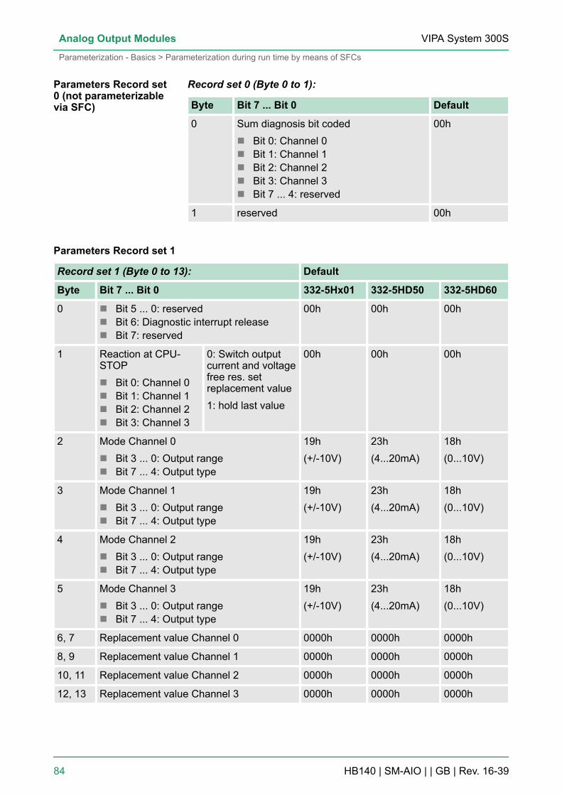
Record set 0 (Byte 0 to 1):
Byte Bit 7 ... Bit 0 Default
0 Sum diagnosis bit codedn Bit 0: Channel 0n Bit 1: Channel 1n Bit 2: Channel 2n Bit 3: Channel 3n Bit 7 ... 4: reserved
00h
1 reserved 00h
Parameters Record set 1
Record set 1 (Byte 0 to 13): Default
Byte Bit 7 ... Bit 0 332-5Hx01 332-5HD50 332-5HD60
0 n Bit 5 ... 0: reservedn Bit 6: Diagnostic interrupt releasen Bit 7: reserved
00h 00h 00h
1 Reaction at CPU-STOPn Bit 0: Channel 0n Bit 1: Channel 1n Bit 2: Channel 2n Bit 3: Channel 3
0: Switch outputcurrent and voltagefree res. setreplacement value1: hold last value
00h 00h 00h
2 Mode Channel 0n Bit 3 ... 0: Output rangen Bit 7 ... 4: Output type
19h(+/-10V)
23h(4...20mA)
18h(0...10V)
3 Mode Channel 1n Bit 3 ... 0: Output rangen Bit 7 ... 4: Output type
19h(+/-10V)
23h(4...20mA)
18h(0...10V)
4 Mode Channel 2n Bit 3 ... 0: Output rangen Bit 7 ... 4: Output type
19h(+/-10V)
23h(4...20mA)
18h(0...10V)
5 Mode Channel 3n Bit 3 ... 0: Output rangen Bit 7 ... 4: Output type
19h(+/-10V)
23h(4...20mA)
18h(0...10V)
6, 7 Replacement value Channel 0 0000h 0000h 0000h
8, 9 Replacement value Channel 1 0000h 0000h 0000h
10, 11 Replacement value Channel 2 0000h 0000h 0000h
12, 13 Replacement value Channel 3 0000h 0000h 0000h
Parameters Record set0 (not parameterizablevia SFC)
VIPA System 300SAnalog Output Modules
Parameterization - Basics > Parameterization during run time by means of SFCs
HB140 | SM-AIO | | GB | Rev. 16-39 84

With setting the mode parameter to 00h the accordingchannel is deactivated. To switch at not symmetricoutput range the current respectively the voltage outputto 0 value at CPU STOP, the following replacementvalues should be used:output range 1...5V: 0V « -6912dec = E500houtput range 4...20mA: 0mA « -6912dec = E500h
Please regard as soon as you release the diagnostic interrupt at runtime, the according group diagnostics are just activated during hard-ware configuration. Otherwise no interrupt can be initialized. Moreinformation can be found at "Diagnostics" further down.
Here the module reaction at CPU-STOP can be set. You have the fol-lowing possibilities:n 0CV: output de-energized (according to the module)n KLV: Keep last valuen SV: Substitute a value
Depending on the module at the register "Outputs" at Output the typevoltage, current output or deactivated and the according range can beselected. As shown in the following illustration the parameter mode ismade up of the coding of the output range and type during run timeparameterization each channel.
The corresponding codes can be found in the following table. Withinthe output types the output ranges are specified, for which a binaryoutput range code is to be specified in each case.
Release diagnosticinterrupt
CPU-Stop reaction
Get mode output typeoutput range
VIPA System 300S Analog Output Modules
Parameterization - Basics > Parameterization during run time by means of SFCs
HB140 | SM-AIO | | GB | Rev. 16-39 85
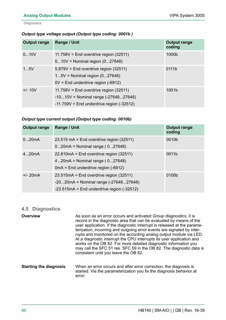
Output type voltage output (Output type coding: 0001b )
Output range Range / Unit Output rangecoding
0...10V 11.758V = End overdrive region (32511)0...10V = Nominal region (0...27648)
1000b
1...5V 5.879V = End overdrive region (32511)1...5V = Nominal region (0...27648)0V = End underdrive region (-6912)
0111b
+/- 10V 11.758V = End overdrive region (32511)-10...10V = Nominal range (-27648...27648)-11.759V = End underdrive region (-32512)
1001b
Output type current output (Output type coding: 0010b)
Output range Range / Unit Output rangecoding
0...20mA 23.515 mA = End overdrive region (32511)0...20mA = Nominal range ( 0...27648)
0010b
4...20mA 22.810mA = End overdrive region (32511)4...20mA = Nominal range ( 0...27648)0mA = End underdrive region (-6912)
0011b
+/- 20mA 23.515mA = End overdrive region (32511)-20...20mA = Nominal range (-27648...27648)-23.515mA = End underdrive region (-32512)
0100b
4.5 DiagnosticsAs soon as an error occurs and activated Group diagnostics, it isrecord in the diagnostic area that can be evaluated by means of theuser application. If the diagnostic interrupt is released at the parame-terization, incoming and outgoing error events are signaled by inter-rupts and monitored on the according analog output module via LED.At a diagnostic interrupt the CPU interrupts its user application andworks on the OB 82. For more detailed diagnostic information youmay call the SFC 51 res. SFC 59 in the OB 82. The diagnostic data isconsistent until you leave the OB 82.
When an error occurs and after error correction, the diagnosis isstarted. Via the parameterization you fix the diagnosis behavior aterror:
Overview
Starting the diagnosis
VIPA System 300SAnalog Output Modules
Diagnostics
HB140 | SM-AIO | | GB | Rev. 16-39 86
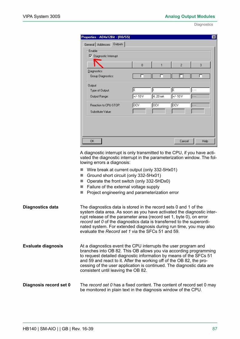
A diagnostic interrupt is only transmitted to the CPU, if you have acti-vated the diagnostic interrupt in the parameterization window. The fol-lowing errors a diagnosis:n Wire break at current output (only 332-5Hx01)n Ground short circuit (only 332-5Hx01)n Operate the front switch (only 332-5HDx0)n Failure of the external voltage supplyn Project engineering and parameterization error
The diagnostics data is stored in the record sets 0 and 1 of thesystem data area. As soon as you have activated the diagnostic inter-rupt release of the parameter area (record set 1, byte 0), on errorrecord set 0 of the diagnostics data is transferred to the superordi-nated system. For extended diagnosis during run time, you may alsoevaluate the Record set 1 via the SFCs 51 and 59.
At a diagnostics event the CPU interrupts the user program andbranches into OB 82. This OB allows you via according programmingto request detailed diagnostic information by means of the SFCs 51and 59 and react to it. After the working off of the OB 82, the pro-cessing of the user application is continued. The diagnostic data areconsistent until leaving the OB 82.
The record set 0 has a fixed content. The content of record set 0 maybe monitored in plain text in the diagnosis window of the CPU.
Diagnostics data
Evaluate diagnosis
Diagnosis record set 0
VIPA System 300S Analog Output Modules
Diagnostics
HB140 | SM-AIO | | GB | Rev. 16-39 87
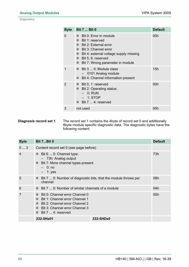
Byte Bit 7 ... Bit 0 Default
0 n Bit 0: Error in modulen Bit 1: reservedn Bit 2: External errorn Bit 3: Channel errorn Bit 4: external voltage supply missingn Bit 5, 6: reservedn Bit 7: Wrong parameter in module
00h
1 n Bit 3 ... 0: Module class– 0101 Analog module
n Bit 4: Channel information present
15h
2 n Bit 0, 1: reservedn Bit 2: Operating status:
– 0: RUN– 1: STOP
n Bit 7 ... 4: reserved
00h
3 not used 00h
The record set 1 contains the 4byte of record set 0 and additionally8byte module specific diagnostic data. The diagnostic bytes have thefollowing content:
Byte Bit 7...Bit 0 Default
0 ... 3 Content record set 0 (see page before)
4 n Bit 6 ... 0: Channel type:– 73h: Analog output
n Bit 7: More channel types present– 0: no– 1: yes
73h
5 n Bit 7 ... 0: Number of diagnostic bits, that the module throws perchannel
08h
6 n Bit 7 ... 0: Number of similar channels of a module 04h
7 n Bit 0: Channel error Channel 0n Bit 1: Channel error Channel 1n Bit 2: Channel error Channel 2n Bit 3: Channel error Channel 3n Bit 7 ... 4: reserved
00h
332-5Hx01 332-5HDx0
Diagnosis record set 1
VIPA System 300SAnalog Output Modules
Diagnostics
HB140 | SM-AIO | | GB | Rev. 16-39 88
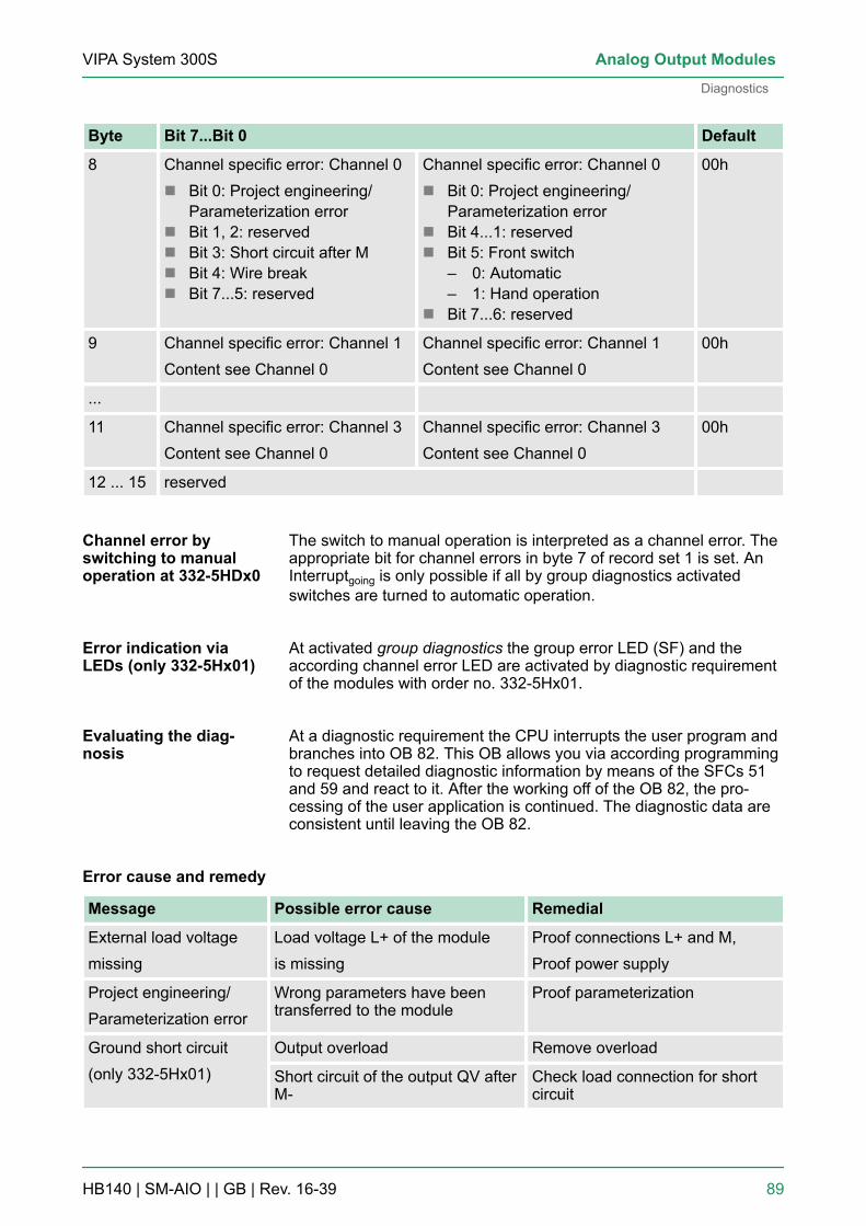
Byte Bit 7...Bit 0 Default
8 Channel specific error: Channel 0n Bit 0: Project engineering/
Parameterization errorn Bit 1, 2: reservedn Bit 3: Short circuit after Mn Bit 4: Wire breakn Bit 7...5: reserved
Channel specific error: Channel 0n Bit 0: Project engineering/
Parameterization errorn Bit 4...1: reservedn Bit 5: Front switch
– 0: Automatic– 1: Hand operation
n Bit 7...6: reserved
00h
9 Channel specific error: Channel 1Content see Channel 0
Channel specific error: Channel 1Content see Channel 0
00h
...
11 Channel specific error: Channel 3Content see Channel 0
Channel specific error: Channel 3Content see Channel 0
00h
12 ... 15 reserved
The switch to manual operation is interpreted as a channel error. Theappropriate bit for channel errors in byte 7 of record set 1 is set. AnInterruptgoing is only possible if all by group diagnostics activatedswitches are turned to automatic operation.
At activated group diagnostics the group error LED (SF) and theaccording channel error LED are activated by diagnostic requirementof the modules with order no. 332-5Hx01.
At a diagnostic requirement the CPU interrupts the user program andbranches into OB 82. This OB allows you via according programmingto request detailed diagnostic information by means of the SFCs 51and 59 and react to it. After the working off of the OB 82, the pro-cessing of the user application is continued. The diagnostic data areconsistent until leaving the OB 82.
Message Possible error cause Remedial
External load voltagemissing
Load voltage L+ of the moduleis missing
Proof connections L+ and M,Proof power supply
Project engineering/Parameterization error
Wrong parameters have beentransferred to the module
Proof parameterization
Ground short circuit(only 332-5Hx01)
Output overload Remove overload
Short circuit of the output QV afterM-
Check load connection for shortcircuit
Channel error byswitching to manualoperation at 332-5HDx0
Error indication viaLEDs (only 332-5Hx01)
Evaluating the diag-nosis
Error cause and remedy
VIPA System 300S Analog Output Modules
Diagnostics
HB140 | SM-AIO | | GB | Rev. 16-39 89
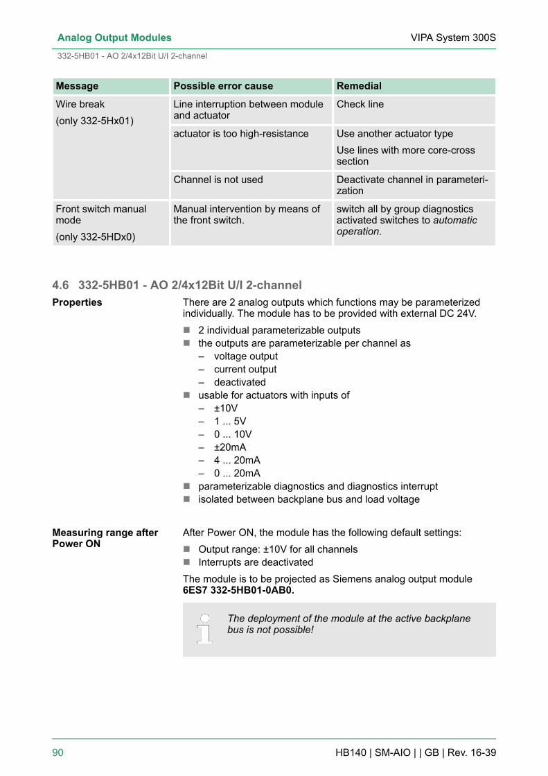
Message Possible error cause Remedial
Wire break(only 332-5Hx01)
Line interruption between moduleand actuator
Check line
actuator is too high-resistance Use another actuator typeUse lines with more core-crosssection
Channel is not used Deactivate channel in parameteri-zation
Front switch manualmode(only 332-5HDx0)
Manual intervention by means ofthe front switch.
switch all by group diagnosticsactivated switches to automaticoperation.
4.6 332-5HB01 - AO 2/4x12Bit U/I 2-channelThere are 2 analog outputs which functions may be parameterizedindividually. The module has to be provided with external DC 24V.n 2 individual parameterizable outputsn the outputs are parameterizable per channel as
– voltage output– current output– deactivated
n usable for actuators with inputs of– ±10V– 1 ... 5V– 0 ... 10V– ±20mA– 4 ... 20mA– 0 ... 20mA
n parameterizable diagnostics and diagnostics interruptn isolated between backplane bus and load voltage
After Power ON, the module has the following default settings:n Output range: ±10V for all channelsn Interrupts are deactivatedThe module is to be projected as Siemens analog output module6ES7 332-5HB01-0AB0.
The deployment of the module at the active backplanebus is not possible!
Properties
Measuring range afterPower ON
VIPA System 300SAnalog Output Modules
332-5HB01 - AO 2/4x12Bit U/I 2-channel
HB140 | SM-AIO | | GB | Rev. 16-39 90

1 LEDs2 flap with labeling strip3 contact bar4 flap opened with inner label
Structure
VIPA System 300S Analog Output Modules
332-5HB01 - AO 2/4x12Bit U/I 2-channel
HB140 | SM-AIO | | GB | Rev. 16-39 91

Pin assignment/LED
Pin Circuit diagram LED Description
1 SF LED (red)Sum error, flashesat missing ext.voltage supply
2
3
4
5
6
7
8
9
10
11 Q0 ... Q1 LED (green)the accordingchannel is activated
12
13
14
15
16
17
18
19
20 F0 ... F1 LED (red)Error channel 0 ... 1
Please regard, that you must not connect the S-Pin atcurrent output!
CAUTION!Please regard that the modules do not have hardwareprecautions against wrong parameterization. The set-ting of the according measuring range is exclusively atthe project engineering.
VIPA System 300SAnalog Output Modules
332-5HB01 - AO 2/4x12Bit U/I 2-channel
HB140 | SM-AIO | | GB | Rev. 16-39 92

LED Description
SF Group error:n On at parameterized group diagnostics, as soon as a
diagnostic entry is present.n On independently from diagnostics at missing external
voltage supply
Q0...Q1 Channel active:On when the according output channel has been activated
F0...F1 Channel error:On together with SF at the according channel with error.
4.6.1 Technical data
Order no. 332-5HB01
Type SM 332
SPEED-Bus -
Current consumption/power loss
Current consumption from backplane bus 100 mA
Power loss 2.5 W
Technical data analog outputs
Number of outputs 2
Cable length, shielded -
Rated load voltage DC 24 V
Reverse polarity protection of rated loadvoltage
-
Current consumption from load voltage L+(without load)
70 mA
Voltage output short-circuit protection ü
Voltage outputs ü
Min. load resistance (voltage range) 1 kΩ
Max. capacitive load (current range) 1 µF
Max. inductive load (current range) 30 mA
Output voltage ranges -10 V ... +10 V0 V ... +10 V+1 V ... +5 V
Operational limit of voltage ranges +/-0.2% ... +/-0.8%
Basic error limit voltage ranges +/-0.1% ... +/-0.5%
Status monitor via LEDs
VIPA System 300S Analog Output Modules
332-5HB01 - AO 2/4x12Bit U/I 2-channel > Technical data
HB140 | SM-AIO | | GB | Rev. 16-39 93

Order no. 332-5HB01
Destruction limit against external appliedvoltage
max. 16V (30V / 10s)
Current outputs ü
Max. in load resistance (current range) 500 Ω
Max. inductive load (current range) 10 mH
Typ. open circuit voltage current output -
Output current ranges -20 mA ... +20 mA0 mA ... +20 mA+4 mA ... +20 mA
Operational limit of current ranges +/-0.3% ... +/-0.8%
Basic error limit current ranges +/-0.2% ... +/-0.5%
Destruction limit against external appliedvoltage
max. 16V (30V / 10s)
Settling time for ohmic load 0.2 ms
Settling time for capacitive load 1 ms
Settling time for inductive load 1 ms
Resolution in bit 13
Conversion time 0.5 ms all channels
Substitute value can be applied yes
Output data size 4 Byte
Status information, alarms, diagnostics
Status display green LED per channel
Interrupts yes
Process alarm no
Diagnostic interrupt yes, parameterizable
Diagnostic functions yes
Diagnostics information read-out possible
Supply voltage display none
Group error display red SF LED
Channel error display red LED per channel
Isolation
Between channels -
Between channels of groups to -
Between channels and backplane bus ü
Between channels and power supply ü
VIPA System 300SAnalog Output Modules
332-5HB01 - AO 2/4x12Bit U/I 2-channel > Technical data
HB140 | SM-AIO | | GB | Rev. 16-39 94

Order no. 332-5HB01
Max. potential difference between circuits -
Max. potential difference between inputs (Ucm) -
Max. potential difference between Mana andMintern (Uiso)
DC 75 V/ AC 50 V
Max. potential difference between inputs andMana (Ucm)
-
Max. potential difference between inputs andMintern (Uiso)
-
Max. potential difference between Mintern andoutputs
-
Insulation tested with DC 500 V
Datasizes
Input bytes 0
Output bytes 4
Parameter bytes 21
Diagnostic bytes 16
Housing
Material PPE
Mounting Rail System 300
Mechanical data
Dimensions (WxHxD) 40 mm x 125 mm x 120 mm
Weight 230 g
Environmental conditions
Operating temperature 0 °C to 60 °C
Storage temperature -25 °C to 70 °C
Certifications
UL certification yes
KC certification yes
The error limits for voltage output were determined with a load R=1GΩ.
The error limits for current output were determined with a load R=10Ω.
Additional Technical data
Order number 332-5HB01
Analog value generation
Resolution (incl. sign)
VIPA System 300S Analog Output Modules
332-5HB01 - AO 2/4x12Bit U/I 2-channel > Technical data
HB140 | SM-AIO | | GB | Rev. 16-39 95

Order number 332-5HB01
±10V; ±20mA 12Bit + sign
1 ... 5V; 4 ... 20mA 11Bit
0 ... 10V; 0 ... 20mA 12Bit
Cycle time (all channels) 0.5ms
Suppression of interference, Limits of Error
Crosstalk between outputs > 40dB
Temperature error(with reference to the output range)
±0.01%/K
Linearity error(with reference to the output range)
±0.1%
Repeatability(in steady state at 25°C, referred to outputrange)
±0.05%
Output ripple; Range 0 to 50kHz(referred to output range)
±0.05%
4.7 332-5HD01 - AO 2/4x12Bit U/I 4-channelThere are 4 analog outputs which functions may be parameterizedindividually. The module has to be provided with external DC 24V.n 4 individual parameterizable outputsn the outputs are parameterizable per channel as
– voltage output– current output– deactivated
n usable for actuators with inputs of– ±10V– 1 ... 5V– 0 ... 10V– ±20mA– 4 ... 20mA– 0 ... 20mA
n parameterizable diagnostics and diagnostics interruptn isolated between backplane bus and load voltage
After Power ON, the module has the following default settings:n Output range: ±10V for all channelsn Interrupts are deactivatedThe module is to be projected as Siemens analog output module6ES7 332-5HD01-0AB0
Properties
Measuring range afterPower ON
VIPA System 300SAnalog Output Modules
332-5HD01 - AO 2/4x12Bit U/I 4-channel
HB140 | SM-AIO | | GB | Rev. 16-39 96

The deployment of the module at the active backplanebus is not possible!
1 LEDs2 flap with labeling strip3 contact bar4 flap opened with inner label
Structure
VIPA System 300S Analog Output Modules
332-5HD01 - AO 2/4x12Bit U/I 4-channel
HB140 | SM-AIO | | GB | Rev. 16-39 97

Pin assignment/LED
Pin Circuit diagram LED Description
1 SF LED (red)Sum error, flashesat missing externalvoltage supply
2
3
4
5
6
7
8
9
10
11 Q0 ... Q1 LED (green)the accordingchannel is activated
12
13
14
15
16
17
18
19
20 F0 ... F3 LED (red)Error channel 0 ... 3
Please regard, that you must not connect the S-Pin atcurrent output!
CAUTION!Please regard that the modules do not have hardwareprecautions against wrong parameterization. The set-ting of the according measuring range is exclusively atthe project engineering.
VIPA System 300SAnalog Output Modules
332-5HD01 - AO 2/4x12Bit U/I 4-channel
HB140 | SM-AIO | | GB | Rev. 16-39 98

LED Description
SF Group error:n On at parameterized group diagnostics, as soon as a
diagnostic entry is present.n On independently from diagnostics at missing external
voltage supply.
Q0...Q3 Channel active:On when the according output channel has been acti-vated.
F0...F3 Channel error:On together with SF at the according channel with error.
4.7.1 Technical data
Order no. 332-5HD01
Type SM 332
SPEED-Bus -
Current consumption/power loss
Current consumption from backplane bus 125 mA
Power loss 3.5 W
Technical data analog outputs
Number of outputs 4
Cable length, shielded -
Rated load voltage DC 24 V
Reverse polarity protection of rated loadvoltage
-
Current consumption from load voltage L+(without load)
115 mA
Voltage output short-circuit protection ü
Voltage outputs ü
Min. load resistance (voltage range) 1 kΩ
Max. capacitive load (current range) 1 µF
Max. inductive load (current range) 30 mA
Output voltage ranges -10 V ... +10 V0 V ... +10 V+1 V ... +5 V
Operational limit of voltage ranges +/-0.2% ... +/-0.8%
Basic error limit voltage ranges +/-0.1% ... +/-0.5%
Status monitor via LEDs
VIPA System 300S Analog Output Modules
332-5HD01 - AO 2/4x12Bit U/I 4-channel > Technical data
HB140 | SM-AIO | | GB | Rev. 16-39 99

Order no. 332-5HD01
Destruction limit against external appliedvoltage
max. 16V (30V / 10s)
Current outputs ü
Max. in load resistance (current range) 500 Ω
Max. inductive load (current range) 10 mH
Typ. open circuit voltage current output -
Output current ranges -20 mA ... +20 mA0 mA ... +20 mA+4 mA ... +20 mA
Operational limit of current ranges +/-0.3% ... +/-0.8%
Basic error limit current ranges +/-0.2% ... +/-0.5%
Destruction limit against external appliedvoltage
max. 16V (30V / 10s)
Settling time for ohmic load 0.2 ms
Settling time for capacitive load 1 ms
Settling time for inductive load 1 ms
Resolution in bit 13
Conversion time 1 ms all channels
Substitute value can be applied yes
Output data size 8 Byte
Status information, alarms, diagnostics
Status display green LED per channel
Interrupts yes
Process alarm no
Diagnostic interrupt yes, parameterizable
Diagnostic functions yes
Diagnostics information read-out possible
Supply voltage display none
Group error display red SF LED
Channel error display red LED per channel
Isolation
Between channels -
Between channels of groups to -
Between channels and backplane bus ü
Between channels and power supply ü
VIPA System 300SAnalog Output Modules
332-5HD01 - AO 2/4x12Bit U/I 4-channel > Technical data
HB140 | SM-AIO | | GB | Rev. 16-39 100

Order no. 332-5HD01
Max. potential difference between circuits -
Max. potential difference between inputs (Ucm) -
Max. potential difference between Mana andMintern (Uiso)
DC 75 V/ AC 50 V
Max. potential difference between inputs andMana (Ucm)
-
Max. potential difference between inputs andMintern (Uiso)
-
Max. potential difference between Mintern andoutputs
-
Insulation tested with DC 500 V
Datasizes
Input bytes 0
Output bytes 8
Parameter bytes 21
Diagnostic bytes 16
Housing
Material PPE
Mounting Rail System 300
Mechanical data
Dimensions (WxHxD) 40 mm x 125 mm x 120 mm
Weight 230 g
Environmental conditions
Operating temperature 0 °C to 60 °C
Storage temperature -25 °C to 70 °C
Certifications
UL certification yes
KC certification yes
The error limits for voltage output were determined with a load R=1GΩ.
The error limits for current output were determined with a load R=10Ω.
Additional Technical data
Order number 332-5HD01
Analog value generation
Resolution (incl. sign)
VIPA System 300S Analog Output Modules
332-5HD01 - AO 2/4x12Bit U/I 4-channel > Technical data
HB140 | SM-AIO | | GB | Rev. 16-39 101
Order number 332-5HD01
±10V; ±20mA 12Bit + sign
1 ... 5V; 4 ... 20mA 11Bit
0 ... 10V; 0 ... 20mA 12Bit
Cycle time (all channels) 1ms
Suppression of interference, Limits of Error
Crosstalk between outputs > 40dB
Temperature error (with reference to the outputrange)
±0.01%/K
Linearity error (with reference to the outputrange)
±0.1%
Repeatability (in steady state at 25°C, referredto output range)
±0.05%
Output ripple; Range 0 to 50kHz (referred tooutput range)
±0.05%
4.8 332-5HD50 - AO 4x12Bit I for manual operationFor each channel there is a 2pole switch with associated potentiom-eter on the front side of the two modules. An analog value may bepreset by the potentiometer, which is issued at the correspondingchannel by switching to manual operation. The module has to be pro-vided with external DC 24V.n 4 individual parameterizable outputsn the outputs are parameterizable per channel as:
– Current output 4...20mA– deactivated
n usable for actuators with an input of 4 ... 20mAn parameterizable diagnostics and diagnostics interruptn 1 switch each channel (Automatic-/Manual operation)n 1 potentiometer each channeln isolated between backplane bus and load voltagen status LED for power supply
After PowerON the interrupts are deactivated.
The modules have are to be configured as 6ES7 332-5HD01 fromSiemens.Ä Chapter 4.4 ‘Parameterization - Basics’ on page 82
Properties
Measuring range afterPowerON
VIPA System 300SAnalog Output Modules
332-5HD50 - AO 4x12Bit I for manual operation
HB140 | SM-AIO | | GB | Rev. 16-39 102

1 LED L+2 flap with labeling strip3 switch: H/A Manual-/Automatic operation4 potentiometer5 contact bar6 flap opened with inner label
Structure
VIPA System 300S Analog Output Modules
332-5HD50 - AO 4x12Bit I for manual operation
HB140 | SM-AIO | | GB | Rev. 16-39 103

Pin assignment/LED
Pin Circuit diagram LED Description
1 L+ LED (green)supply voltage is on2
3
4
5
6
7
8
9
10
11
12
13
14
15
16
17
18
19
20
Schematic diagram
VIPA System 300SAnalog Output Modules
332-5HD50 - AO 4x12Bit I for manual operation
HB140 | SM-AIO | | GB | Rev. 16-39 104

4.8.1 Manual operationFor each channel there is a 2pole switch with associated potentiom-eter on the front side. The operating mode automatic or manual maybe toggled by the switch. At manual operation the module issues thevalue at the according channel adjusted by the potentiometer.Depending on the switch position there is the following action:
Front switch Description
Manual operation Issues at the output channel the value adjusted by the potentiometer.Note! As long as the module is supplied with DC 24V, in manualoperation, independently of the mode of operation of the CPU, the bypotentiometer adjusted value is issued at the output channel.
Automatic operation The channel operates as a "normal" analog output channel and can becontrolled by PLC program.
For each channel there is a potentiometer on the front side. Here youcan preset an analog value from min. up to max. of the nominalrange. If the potentiometer is turned in the clockwise direction beyondthe max. position, then the overdrive region is reached. Hardwareconditionally an exact marking of the ranges is not possible. As soonas you turn the switch into position "H" (manual operation), the valueadjusted by the potentiometer is issued at the according outputchannel. Depending on the module there are the following ranges:
Order no. Nominal range(min. ... max.)
max. overdrive region
332-5HD50 4...20mA ca. 24mA
332-5HD60 0...10V ca. 12V
The switch to manual operation is interpreted as a channel error. Theappropriate bit for channel errors in byte 7 of the diagnostics recordset 1 is set. An Interruptgoing is only possible if all by group diagnosticsactivated switches are turned to automatic operation. Ä Chapter 4.5‘Diagnostics ’ on page 86
Manual operation
Potentiometer
Channel error byswitching to manualoperation
VIPA System 300S Analog Output Modules
332-5HD50 - AO 4x12Bit I for manual operation > Manual operation
HB140 | SM-AIO | | GB | Rev. 16-39 105
DANGER!With the modules you can cause a jump in the analogvalue by means of the switch, independently of theCPU operation mode, as long as the module is powersupplied. This could lead to material damage or per-sonal injury! Please regard also that disconnecting res.connecting during operation, the so-called "Hot Swap-ping", is not possible!
4.8.2 Technical data
Order number 332-5HD50
Type SM 332
SPEED-Bus -
Current consumption/power loss
Current consumption from backplane bus 80 mA
Power loss 3.5 W
Technical data analog outputs
Number of outputs 4
Cable length, shielded -
Rated load voltage DC 24 V
Current consumption from load voltage L+(without load)
130 mA
Voltage output short-circuit protection -
Voltage outputs -
Min. load resistance (voltage range) -
Max. capacitive load (current range) -
Output voltage ranges -
Operational limit of voltage ranges -
Basic error limit voltage ranges -
Current outputs ü
Max. in load resistance (current range) 500 Ω
Max. inductive load (current range) 10 mH
Output current ranges +4 mA ... +20 mA
Operational limit of current ranges +/-0.4%
Basic error limit current ranges +/-0.2%
Settling time for ohmic load 0.5 ms
VIPA System 300SAnalog Output Modules
332-5HD50 - AO 4x12Bit I for manual operation > Technical data
HB140 | SM-AIO | | GB | Rev. 16-39 106
Order number 332-5HD50
Settling time for capacitive load -
Settling time for inductive load 0.5 ms
Resolution in bit 12
Conversion time 0.5 ms all channels
Substitute value can be applied yes
Output data size 8 Byte
Status information, alarms, diagnostics
Status display none
Interrupts -
Process alarm no
Diagnostic interrupt yes, parameterizable
Diagnostic functions yes
Diagnostics information read-out possible
Supply voltage display green LED
Group error display none
Channel error display none
Isolation
Between channels -
Between channels of groups to -
Between channels and backplane bus ü
Between channels and power supply ü
Max. potential difference between circuits -
Max. potential difference between inputs (Ucm) -
Max. potential difference between Mana andMintern (Uiso)
DC 75 V/ AC 50 V
Max. potential difference between inputs andMana (Ucm)
-
Max. potential difference between inputs andMintern (Uiso)
-
Max. potential difference between Mintern andoutputs
-
Insulation tested with DC 500 V
Datasizes
Input bytes 0
Output bytes 8
VIPA System 300S Analog Output Modules
332-5HD50 - AO 4x12Bit I for manual operation > Technical data
HB140 | SM-AIO | | GB | Rev. 16-39 107

Order number 332-5HD50
Parameter bytes 21
Diagnostic bytes 16
Housing
Material PPE
Mounting Rail System 300
Mechanical data
Dimensions (WxHxD) 40 x 125 x 120 mm
Weight 250 g
Environmental conditions
Operating temperature 0 °C to 60 °C
Storage temperature -25 °C to 70 °C
Certifications
UL certification yes
The error limits were determined with a load R=10Ω.
Additional Technical data
Order number 332-5HD50
Suppression of interference, Limits of error
Crosstalk between the outputs > 40dB
Temperature error (with reference to the outputrange)
±0.01%/K
Linearity error (with reference to the inputrange)
±0.15%
Repeatability (in steady state at 25°C, referredto output range)
±0.05%
Output ripple; range 0 to 50kHz (referred tooutput range)
±0.05%
Data for selecting an actuator
Current outputs
- No-load voltage 15V
Destruction limit against voltage/currentsapplied from outside
- Voltage at outputs to MANA max. 15V
- Current max. 25mA
Connecting actuators
- 2-conductor connection possible
VIPA System 300SAnalog Output Modules
332-5HD50 - AO 4x12Bit I for manual operation > Technical data
HB140 | SM-AIO | | GB | Rev. 16-39 108
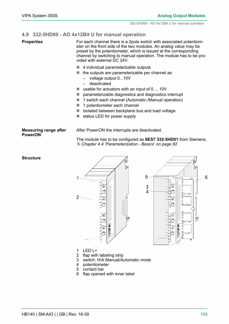
4.9 332-5HD60 - AO 4x12Bit U for manual operationFor each channel there is a 2pole switch with associated potentiom-eter on the front side of the two modules. An analog value may bepreset by the potentiometer, which is issued at the correspondingchannel by switching to manual operation. The module has to be pro-vided with external DC 24V.n 4 individual parameterizable outputsn the outputs are parameterizable per channel as:
– voltage output 0...10V– deactivated
n usable for actuators with an input of 0 ... 10Vn parameterizable diagnostics and diagnostics interruptn 1 switch each channel (Automatic-/Manual operation)n 1 potentiometer each channeln isolated between backplane bus and load voltagen status LED for power supply
After PowerON the interrupts are deactivated.
The module has to be configured as 6ES7 332-5HD01 from Siemens.Ä Chapter 4.4 ‘Parameterization - Basics’ on page 82
1 LED L+2 flap with labeling strip3 switch: H/A Manual/Automatic mode4 potentiometer5 contact bar6 flap opened with inner label
Properties
Measuring range afterPowerON
Structure
VIPA System 300S Analog Output Modules
332-5HD60 - AO 4x12Bit U for manual operation
HB140 | SM-AIO | | GB | Rev. 16-39 109

Pin assignment/LED
Pin Circuit diagram LED Description
1 L+ LED (green)supply voltage ison
2
3
4
5
6
7
8
9
10
11
12
13
14
15
16
17
18
19
20
Schematic diagram
VIPA System 300SAnalog Output Modules
332-5HD60 - AO 4x12Bit U for manual operation
HB140 | SM-AIO | | GB | Rev. 16-39 110

4.9.1 Manual operationFor each channel there is a 2pole switch with associated potentiom-eter on the front side. The operating mode automatic or manual maybe toggled by the switch. At manual operation the module issues thevalue at the according channel adjusted by the potentiometer.Depending on the switch position there is the following action:
Front switch Description
Manual operation Issues at the output channel the value adjusted by the potentiometer.Note! As long as the module is supplied with DC 24V, in manualoperation, independently of the mode of operation of the CPU, the bypotentiometer adjusted value is issued at the output channel.
Automatic operation The channel operates as a "normal" analog output channel and can becontrolled by PLC program.
For each channel there is a potentiometer on the front side. Here youcan preset an analog value from min. up to max. of the nominalrange. If the potentiometer is turned in the clockwise direction beyondthe max. position, then the overdrive region is reached. Hardwareconditionally an exact marking of the ranges is not possible. As soonas you turn the switch into position "H" (manual operation), the valueadjusted by the potentiometer is issued at the according outputchannel. Depending on the module there are the following ranges:
Order no. Nominal range(min. ... max.)
max. overdriveregion
332-5HD50 4...20mA ca. 24mA
332-5HD60 0...10V ca. 12V
The switch to manual operation is interpreted as a channel error. Theappropriate bit for channel errors in byte 7 of the diagnostics recordset 1 is set. An Interruptgoing is only possible if all by group diagnosticsactivated switches are turned to automatic operation. Ä Chapter 4.5‘Diagnostics ’ on page 86
Manual operation
Potentiometer
Channel error byswitching to manualoperation
VIPA System 300S Analog Output Modules
332-5HD60 - AO 4x12Bit U for manual operation > Manual operation
HB140 | SM-AIO | | GB | Rev. 16-39 111

DANGER!With the modules you can cause a jump in the analogvalue by means of the switch, independently of theCPU operation mode, as long as the module is powersupplied. This could lead to material damage or per-sonal injury! Please regard also that disconnecting res.connecting during operation, the so-called "Hot Swap-ping", is not possible!
4.9.2 Technical data
Order number 332-5HD60
Type SM 332
SPEED-Bus -
Current consumption/power loss
Current consumption from backplane bus 80 mA
Power loss 3.5 W
Technical data analog outputs
Number of outputs 4
Cable length, shielded -
Rated load voltage DC 24 V
Current consumption from load voltage L+ (without load) 130 mA
Voltage output short-circuit protection ü
Voltage outputs ü
Min. load resistance (voltage range) 1 kΩ
Max. capacitive load (current range) 1 µF
Output voltage ranges 0 V ... +10 V
Operational limit of voltage ranges +/-0.4%
Basic error limit voltage ranges +/-0.2%
Current outputs -
Max. in load resistance (current range) -
Max. inductive load (current range) -
Output current ranges -
Operational limit of current ranges -
Basic error limit current ranges -
Settling time for ohmic load 1.5 ms
Settling time for capacitive load 1.5 ms
VIPA System 300SAnalog Output Modules
332-5HD60 - AO 4x12Bit U for manual operation > Technical data
HB140 | SM-AIO | | GB | Rev. 16-39 112

Order number 332-5HD60
Settling time for inductive load -
Resolution in bit 12
Conversion time 0.5 ms all channels
Substitute value can be applied yes
Output data size 8 Byte
Status information, alarms, diagnostics
Status display none
Interrupts -
Process alarm no
Diagnostic interrupt yes, parameterizable
Diagnostic functions yes
Diagnostics information read-out possible
Supply voltage display green LED
Group error display none
Channel error display none
Isolation
Between channels -
Between channels of groups to -
Between channels and backplane bus ü
Between channels and power supply ü
Max. potential difference between circuits -
Max. potential difference between inputs (Ucm) -
Max. potential difference between Mana and Mintern(Uiso)
DC 75 V/ AC 50 V
Max. potential difference between inputs and Mana (Ucm) -
Max. potential difference between inputs and Mintern(Uiso)
-
Max. potential difference between Mintern and outputs -
Insulation tested with DC 500 V
Datasizes
Input bytes 0
Output bytes 8
Parameter bytes 21
Diagnostic bytes 16
Housing
VIPA System 300S Analog Output Modules
332-5HD60 - AO 4x12Bit U for manual operation > Technical data
HB140 | SM-AIO | | GB | Rev. 16-39 113

Order number 332-5HD60
Material PPE
Mounting Rail System 300
Mechanical data
Dimensions (WxHxD) 40 x 125 x 120 mm
Weight 250 g
Environmental conditions
Operating temperature 0 °C to 60 °C
Storage temperature -25 °C to 70 °C
Certifications
UL certification yes
The error limits were determined with a load R=1GΩ.
Additional Technical data
Order number 332-5HD60
Suppression of interference, Limits of error
Crosstalk between the outputs > 40dB
Temperature error (with reference to the output range) ±0.01%/K
Linearity error (with reference to the input range) ±0.15%
Repeatability (in steady state at 25°C, referred to outputrange)
±0.05%
Output ripple; range 0 to 50kHz (referred to output range) ±0.05%
Data for selecting an actuator
Voltage outputs
- Short-circuit protection yes
- Short-circuit current 25mA
Destruction limit against voltage/currents applied from out-side
- Voltage at outputs to MANA max. 15V
- Current max. 30mA
Connecting actuators
- conductor connection possible
VIPA System 300SAnalog Output Modules
332-5HD60 - AO 4x12Bit U for manual operation > Technical data
HB140 | SM-AIO | | GB | Rev. 16-39 114

5 Analog I/O Modules5.1 General
For analog signals you should use isolated cables to reduce interfer-ence. The cable screening should be grounded at both ends. If thereare differences in the potential between the cable ends, there mayoccur a potential compensating current that could disturb the analogsignals. In this case you should ground the cable screening only atone end.
Please take always care of the correct polarity whenconnecting! Please install short circuits at non-usedinputs by connecting the positive contact with thechannel ground. Please leave the output pins of notused channels disconnected and configure the outputtype of the channel to "deactivated". In this way thecycle time of the module gets shorter.
The module may be configured by means of a hardware configurationor rather during run time by SFCs.After PowerON, the module has the following default settings:n Input range: Pt100 Climate (RTD-4L)n Output range: voltage 0 ... 10V
5.2 Analog value representationAs soon as a measuring value exceeds the overdrive res. underdriverange, the following value is returned:Measuring value > Overdrive range: 32767 (7FFFh)Measuring value < Underdrive range: -32768 (8000h)At parameterization error or de-activated analog part the measuringvalue 32767 (7FFFh) is returned. When leaving the defined rangeduring analog output 0V is issued. In the following all measuringranges are specified, which are supported by the analog part. Withthe formulas it may be converted between measuring and analogvalue.
The analog values are represented in two’s complement format.
Analog value
High byte Low byte
Bit number 15 14 13 12 11 10 9 8 7 6 5 4 3 2 1 0
Resolution SG Analog value (word)
12bit+sign SG Relevant output value X X X
*) The least significant irrelevant bits of the output value are marked by "X".
Cables for analog sig-nals
Parameterization
General
Numeric notation in Sie-mens S7 format
VIPA System 300S Analog I/O Modules
Analog value representation
HB140 | SM-AIO | | GB | Rev. 16-39 115

Sign bit (SG)The algebraic sign bit is represented by Bit 15. Here it is essential:n Bit 15 = "0" ® positive valuen Bit 15 = "1" ® negative value
Formulas for the conversion:
U: voltage, D: decimal value
0...10V dec. hex. Range
> 11.759 32767 7FFFh Overflow
11.759V 32511 7EFFhOverdrive range
... ... ...
10V 27648 6C00h Nominal range
... ... ...
0V 0 0
Negative values not possible Underdrive range
Formulas for the conversion:
R: resistance value, D: decimal value
10kW dec. hex. Range
11.852kW 32767 7FFFh Overflow
32512 7F00h
11.759kW 32511 7EFFh
Overdrive range. 27649 6C01h
... ... ...
10kW 27648 6C00h
Nominal range7.5kW 20736 5100h
361.7mW 1 0001h
Voltage measuringrange 0 ... 10V
Resistance measure-ment R-4L (0 ... 10kΩ)
VIPA System 300SAnalog I/O Modules
Analog value representation
HB140 | SM-AIO | | GB | Rev. 16-39 116

10kW dec. hex. Range
0W 0 0000h
Negative values not possible Underdrive range
With Pt 100 the temperature is directly shown with the adjusted unit.Here applies: 1 Digit = 0.01 temperature unit.
Pt100 Pt100 Range
in °C (1digit=0.01°C)
dec. hex. in °F(1digit=0.01°F)
dec. hex.
>155.0 32767 7FFFh >311.0 32767 7FFFh Overflow
155.0 15500 3C8Ch 311.0 31100 797Ch Overdriverange
... ... ... ... ... ...
130.0 13000 32C8h 266.0 26600 67E8h Nominalrange
... ... ... ... ... ...
-120.0 -12000 D120h -184.0 -18400 B820h
... ... ... ... ... ... Underdriverange
-145.0 -14500 C75Ch -229.0 -22900 A68Ch
< -145.0 -32768 8000h < -229.0 -32768 8000h Underflow
Formulas for the conversion:
U: voltage, D: decimal value
0...10V dec. hex. Range
0V 32767 7FFFh Overflow
... ... ....
11.76V 32511 7EFFhOverdrive range
... ... ...
10V 27648 6C00h Nominal range
... ... ...
0V 0 0
... ... ... Underdrive range
Resistance thermom-eter (Pt100 Climate)
Voltage output range0 ... 10V
VIPA System 300S Analog I/O Modules
Analog value representation
HB140 | SM-AIO | | GB | Rev. 16-39 117

0...10V dec. hex. Range
0V -6912 E500h
... ... ... Underflow
0V -32768 8000h
5.3 ParameterizationThere are the following possibilities for parameterization:n Parameterization by hardware configuration of Siemens SIMATIC
manager or with WinPLC7 from VIPA.n Parameterization during run time by means of SFCs.
5.3.1 Parameterization by hardware configurationTo be compatible to the Siemens SIMATIC manager the followingsteps are to be accomplished:1. Start the hardware configurator from Siemens2. Create a new project3. Configure your CPU4. Link-up your System 300V modules in the plugged-in sequence
starting with slot 4.5. Configure the analog in/output module as module from Siemens
with the order number 6ES7 334-0KE00-0AB0.
ð The analog modules may be found at the hardware catalogat Simatic 300 > SM-300.
6. If needed parameterize the CPU respectively the modules. Theparameter window appears as soon as you double click on theaccording module. At this window the according parameter canbe changed.
7. Save your project, switch the CPU to STOP and transfer yourproject to the CPU. As soon as the CPU is switched to RUN theparameters are transferred to the connected modules.
The following parameters may be adjusted at the analog in/outputmodule:n Starting address of the datan Input area (deactivated, integration time, measuring type/range)n Output area (deactivated, voltage output)A closer description of the parameters may be found below.
Overview
Parameters
VIPA System 300SAnalog I/O Modules
Parameterization > Parameterization by hardware configuration
HB140 | SM-AIO | | GB | Rev. 16-39 118
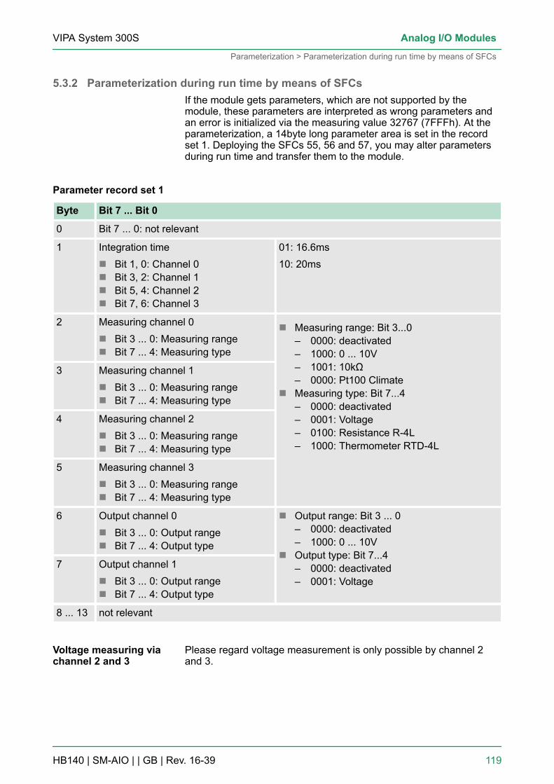
5.3.2 Parameterization during run time by means of SFCsIf the module gets parameters, which are not supported by themodule, these parameters are interpreted as wrong parameters andan error is initialized via the measuring value 32767 (7FFFh). At theparameterization, a 14byte long parameter area is set in the recordset 1. Deploying the SFCs 55, 56 and 57, you may alter parametersduring run time and transfer them to the module.
Byte Bit 7 ... Bit 0
0 Bit 7 ... 0: not relevant
1 Integration timen Bit 1, 0: Channel 0n Bit 3, 2: Channel 1n Bit 5, 4: Channel 2n Bit 7, 6: Channel 3
01: 16.6ms10: 20ms
2 Measuring channel 0n Bit 3 ... 0: Measuring rangen Bit 7 ... 4: Measuring type
n Measuring range: Bit 3...0– 0000: deactivated– 1000: 0 ... 10V– 1001: 10kΩ– 0000: Pt100 Climate
n Measuring type: Bit 7...4– 0000: deactivated– 0001: Voltage– 0100: Resistance R-4L– 1000: Thermometer RTD-4L
3 Measuring channel 1n Bit 3 ... 0: Measuring rangen Bit 7 ... 4: Measuring type
4 Measuring channel 2n Bit 3 ... 0: Measuring rangen Bit 7 ... 4: Measuring type
5 Measuring channel 3n Bit 3 ... 0: Measuring rangen Bit 7 ... 4: Measuring type
6 Output channel 0n Bit 3 ... 0: Output rangen Bit 7 ... 4: Output type
n Output range: Bit 3 ... 0– 0000: deactivated– 1000: 0 ... 10V
n Output type: Bit 7...4– 0000: deactivated– 0001: Voltage
7 Output channel 1n Bit 3 ... 0: Output rangen Bit 7 ... 4: Output type
8 ... 13 not relevant
Please regard voltage measurement is only possible by channel 2and 3.
Parameter record set 1
Voltage measuring viachannel 2 and 3
VIPA System 300S Analog I/O Modules
Parameterization > Parameterization during run time by means of SFCs
HB140 | SM-AIO | | GB | Rev. 16-39 119

5.4 334-0KE00 - AI 4/AO 2x12BitThere are up to 4 analog inputs and 2 analog outputs, which functionsmay be parameterized by groups. The module has to be providedwith external DC 24V.n 4 inputs in 2 groups (1. group only Pt100)n 2 outputs in one groupn Measuring type parameterizable per channel
– voltage– resistor– temperature
n Type of output parameterizable per channel group– voltage
n isolated between backplane bus and load voltage
After PowerON, the module has the following default settings:n Input range: Pt100 Climate (RTD-4L)n Output range: voltage 0 ... 10VThe module is to be configured as module from Siemens with ordernumber 6ES7 334-0KE00-0AB0.
The deployment of the module at the active backplanebus is not possible!
1 LED stripe (without function)2 flap with labeling strip3 contact bar4 flap opened with inner label
Properties
Measuring range afterPowerON
Structure
VIPA System 300SAnalog I/O Modules
334-0KE00 - AI 4/AO 2x12Bit
HB140 | SM-AIO | | GB | Rev. 16-39 120

Pin assignment
Circuit diagram 334-0KE00
CAUTION!Please regard that the module 334-0KE00 does nothave hardware precautions against wrong parameteri-zation. The setting of the according measuring range isexclusively at the project engineering. At the projectengineering you should be very careful. Please regardalso that disconnecting res. connecting during opera-tion, the so-called "Hot Swapping", is not possible!
5.4.1 Technical data
Order no. 334-0KE00
Type SM 334
SPEED-Bus -
Current consumption/power loss
Current consumption from backplane bus 95 mA
VIPA System 300S Analog I/O Modules
334-0KE00 - AI 4/AO 2x12Bit > Technical data
HB140 | SM-AIO | | GB | Rev. 16-39 121
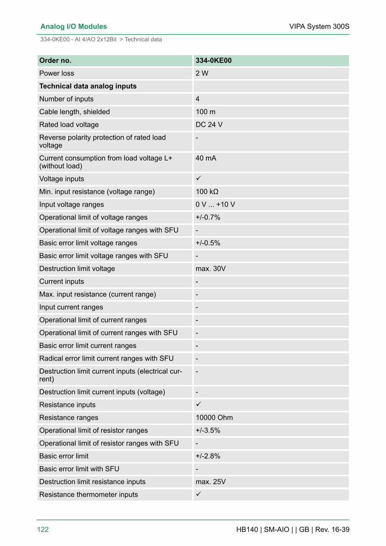
Order no. 334-0KE00
Power loss 2 W
Technical data analog inputs
Number of inputs 4
Cable length, shielded 100 m
Rated load voltage DC 24 V
Reverse polarity protection of rated loadvoltage
-
Current consumption from load voltage L+(without load)
40 mA
Voltage inputs ü
Min. input resistance (voltage range) 100 kΩ
Input voltage ranges 0 V ... +10 V
Operational limit of voltage ranges +/-0.7%
Operational limit of voltage ranges with SFU -
Basic error limit voltage ranges +/-0.5%
Basic error limit voltage ranges with SFU -
Destruction limit voltage max. 30V
Current inputs -
Max. input resistance (current range) -
Input current ranges -
Operational limit of current ranges -
Operational limit of current ranges with SFU -
Basic error limit current ranges -
Radical error limit current ranges with SFU -
Destruction limit current inputs (electrical cur-rent)
-
Destruction limit current inputs (voltage) -
Resistance inputs ü
Resistance ranges 10000 Ohm
Operational limit of resistor ranges +/-3.5%
Operational limit of resistor ranges with SFU -
Basic error limit +/-2.8%
Basic error limit with SFU -
Destruction limit resistance inputs max. 25V
Resistance thermometer inputs ü
VIPA System 300SAnalog I/O Modules
334-0KE00 - AI 4/AO 2x12Bit > Technical data
HB140 | SM-AIO | | GB | Rev. 16-39 122
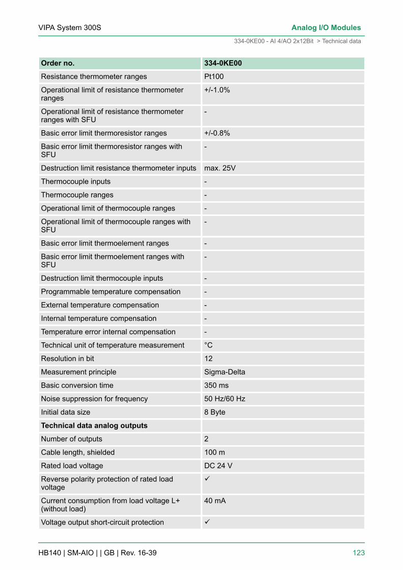
Order no. 334-0KE00
Resistance thermometer ranges Pt100
Operational limit of resistance thermometerranges
+/-1.0%
Operational limit of resistance thermometerranges with SFU
-
Basic error limit thermoresistor ranges +/-0.8%
Basic error limit thermoresistor ranges withSFU
-
Destruction limit resistance thermometer inputs max. 25V
Thermocouple inputs -
Thermocouple ranges -
Operational limit of thermocouple ranges -
Operational limit of thermocouple ranges withSFU
-
Basic error limit thermoelement ranges -
Basic error limit thermoelement ranges withSFU
-
Destruction limit thermocouple inputs -
Programmable temperature compensation -
External temperature compensation -
Internal temperature compensation -
Temperature error internal compensation -
Technical unit of temperature measurement °C
Resolution in bit 12
Measurement principle Sigma-Delta
Basic conversion time 350 ms
Noise suppression for frequency 50 Hz/60 Hz
Initial data size 8 Byte
Technical data analog outputs
Number of outputs 2
Cable length, shielded 100 m
Rated load voltage DC 24 V
Reverse polarity protection of rated loadvoltage
ü
Current consumption from load voltage L+(without load)
40 mA
Voltage output short-circuit protection ü
VIPA System 300S Analog I/O Modules
334-0KE00 - AI 4/AO 2x12Bit > Technical data
HB140 | SM-AIO | | GB | Rev. 16-39 123
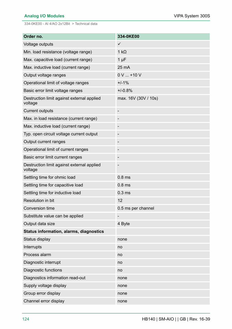
Order no. 334-0KE00
Voltage outputs ü
Min. load resistance (voltage range) 1 kΩ
Max. capacitive load (current range) 1 µF
Max. inductive load (current range) 25 mA
Output voltage ranges 0 V ... +10 V
Operational limit of voltage ranges +/-1%
Basic error limit voltage ranges +/-0.8%
Destruction limit against external appliedvoltage
max. 16V (30V / 10s)
Current outputs -
Max. in load resistance (current range) -
Max. inductive load (current range) -
Typ. open circuit voltage current output -
Output current ranges -
Operational limit of current ranges -
Basic error limit current ranges -
Destruction limit against external appliedvoltage
-
Settling time for ohmic load 0.8 ms
Settling time for capacitive load 0.8 ms
Settling time for inductive load 0.3 ms
Resolution in bit 12
Conversion time 0.5 ms per channel
Substitute value can be applied -
Output data size 4 Byte
Status information, alarms, diagnostics
Status display none
Interrupts no
Process alarm no
Diagnostic interrupt no
Diagnostic functions no
Diagnostics information read-out none
Supply voltage display none
Group error display none
Channel error display none
VIPA System 300SAnalog I/O Modules
334-0KE00 - AI 4/AO 2x12Bit > Technical data
HB140 | SM-AIO | | GB | Rev. 16-39 124

Order no. 334-0KE00
Isolation
Between channels -
Between channels of groups to -
Between channels and backplane bus ü
Between channels and power supply ü
Max. potential difference between circuits -
Max. potential difference between inputs (Ucm) DC 1 V
Max. potential difference between Mana andMintern (Uiso)
DC 75 V/ AC 50 V
Max. potential difference between inputs andMana (Ucm)
DC 1 V
Max. potential difference between inputs andMintern (Uiso)
-
Max. potential difference between Mintern andoutputs
-
Insulation tested with DC 500 V
Datasizes
Input bytes 8
Output bytes 4
Parameter bytes 21
Diagnostic bytes 0
Housing
Material PPE
Mounting Rail System 300
Mechanical data
Dimensions (WxHxD) 40 mm x 125 mm x 120 mm
Weight 210 g
Environmental conditions
Operating temperature 0 °C to 60 °C
Storage temperature -25 °C to 70 °C
Certifications
UL certification yes
KC certification yes
VIPA System 300S Analog I/O Modules
334-0KE00 - AI 4/AO 2x12Bit > Technical data
HB140 | SM-AIO | | GB | Rev. 16-39 125

Additional Technical data
Order number 334-0KE00
Analog value generation of the inputs
Basic conversion time nx72ms
Smoothing of the measured values none
Suppression of interference, Limits of errorof the inputs
Noise suppression for f=n x (f1 ±1%) (f1= inter-ference frequency, n=1,2,...)
- Common mode interference (UCM <13V) > 80dB
- Series mode noise (peak value of noise <Nominal value of input range)
> 80dB
Crosstalk between the inputs > 50dB
Temperature error (with reference to the inputrange)
±0.01%/K
Linearity error (with reference to the inputrange)
±0.005%
Repeatability (in steady state at 25°C, referredto input range)
±0.05%
Suppression of interference, Limits of errorof the outputs
Crosstalk between outputs > 40dB
Temperature error (with reference to the outputrange)
±0.005%/K
Linearity error (with reference to the outputrange)
±0.1%
Repeatability (in steady state at 25°C, with ref-erence to the output range)
±0.05%
Output ripple; Range 0 to 50kHz (with referenceto the output range)
±0.05%
Data for selecting a sensor
Maximum input voltage for voltage input(destruction limit)
30V
Connection of the sensor
- for measuring voltage possible
- for measuring resistance
as 2-conductor connection possible
as 3-conductor connection possible
as 4-conductor connection possible
Characteristic linearization
VIPA System 300SAnalog I/O Modules
334-0KE00 - AI 4/AO 2x12Bit > Technical data
HB140 | SM-AIO | | GB | Rev. 16-39 126

Order number 334-0KE00
- for resistance thermometer Pt100 Climate
Temperature compensation no
Technical unit for temperature measurement °C
Data for selecting an actuator
Load resistance (in the nominal range of theoutputs)
- for voltage outputs min. 1kW
- capacitive load max. 1µF
Destruction limit against voltages/currents
- Voltages at outputs to MANA max. 16V (30V for 10s)
- Current not possible
Connection of actuators
- for voltage output
2-conductor connection possible
4-conductor connection not possible
VIPA System 300S Analog I/O Modules
334-0KE00 - AI 4/AO 2x12Bit > Technical data
HB140 | SM-AIO | | GB | Rev. 16-39 127

6 Analog I/O Modules FAST - SPEED-Bus6.1 General
For analog signals you should use isolated cables to reduce interfer-ence. The cable screening should be grounded at both ends. If thereare differences in the potential between the cable ends, there mayoccur a potential compensating current that could disturb the analogsignals. In this case you should ground the cable screening only atone end.
Depending on the module the following sensors may be connected tothe analog input modules:n Current sensor ±20mAn Voltage sensor ±10V
Please take care of the correct polarity when installingthe sensors! Please install short circuits at non-usedinputs by connecting the positive contact with thechannel ground of the according channel.
The modules may be parameterized by hardware configurationrespectively at run time by means of SFCs.
The modules have diagnostics capability. The following errors canrelease a diagnostic:n Error in parameterizationn Process interrupt lostn Measuring range over-/underflown External power supply is missing
The following events can be defined by parameterization to release aprocess interrupt:n Limit overflown Limit underflown End of cycle as soon as measuring value conversion of every
channel has finished.At a process interrupt 4bytes of process interrupt data are transferred.The process interrupts are deactivated when using oscilloscope- orFIFO functions.
Cables for analog sig-nals
Connecting sensors
Parameterization
Diagnostic functions
Process interrupts
VIPA System 300SAnalog I/O Modules FAST - SPEED-Bus
General
HB140 | SM-AIO | | GB | Rev. 16-39 128
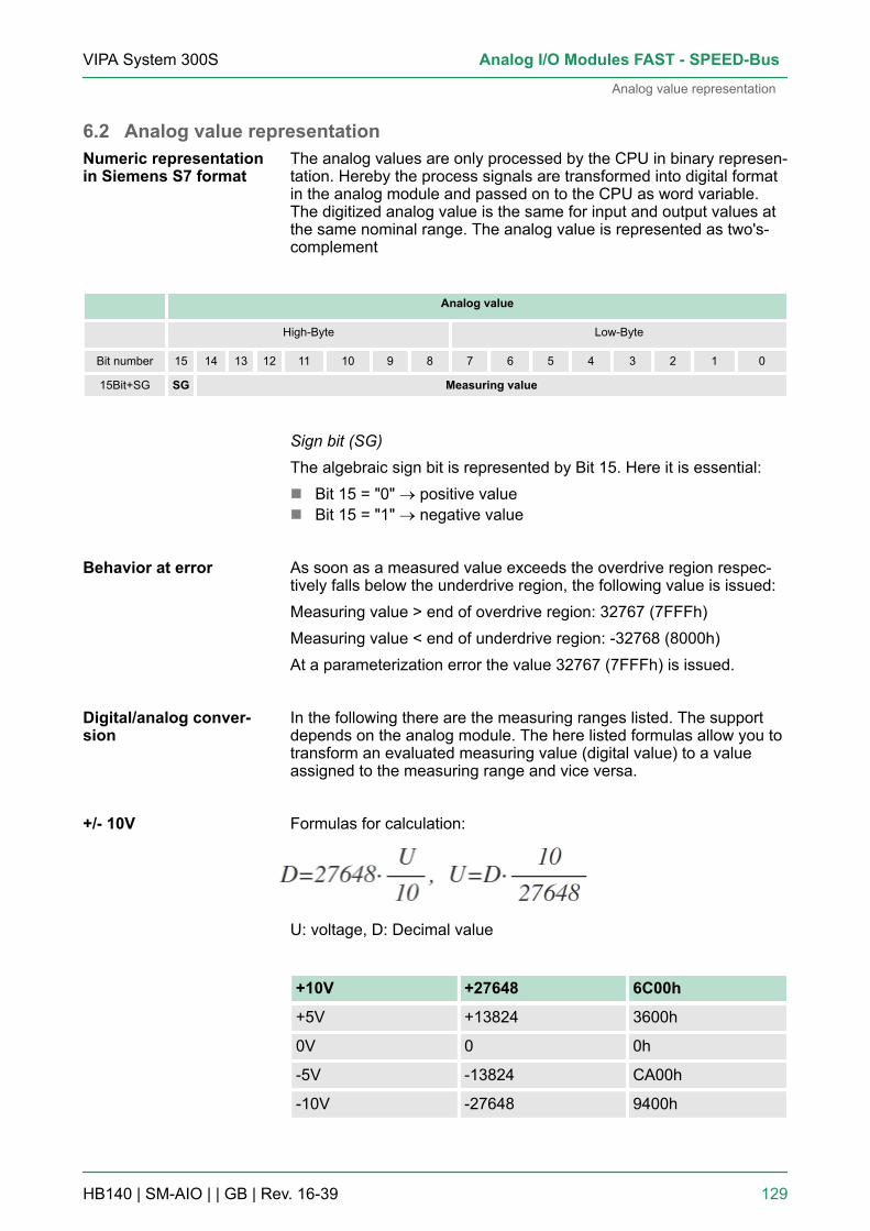
6.2 Analog value representationThe analog values are only processed by the CPU in binary represen-tation. Hereby the process signals are transformed into digital formatin the analog module and passed on to the CPU as word variable.The digitized analog value is the same for input and output values atthe same nominal range. The analog value is represented as two's-complement
Analog value
High-Byte Low-Byte
Bit number 15 14 13 12 11 10 9 8 7 6 5 4 3 2 1 0
15Bit+SG SG Measuring value
Sign bit (SG)The algebraic sign bit is represented by Bit 15. Here it is essential:n Bit 15 = "0" ® positive valuen Bit 15 = "1" ® negative value
As soon as a measured value exceeds the overdrive region respec-tively falls below the underdrive region, the following value is issued:Measuring value > end of overdrive region: 32767 (7FFFh)Measuring value < end of underdrive region: -32768 (8000h)At a parameterization error the value 32767 (7FFFh) is issued.
In the following there are the measuring ranges listed. The supportdepends on the analog module. The here listed formulas allow you totransform an evaluated measuring value (digital value) to a valueassigned to the measuring range and vice versa.
Formulas for calculation:
U: voltage, D: Decimal value
+10V +27648 6C00h
+5V +13824 3600h
0V 0 0h
-5V -13824 CA00h
-10V -27648 9400h
Numeric representationin Siemens S7 format
Behavior at error
Digital/analog conver-sion
+/- 10V
VIPA System 300S Analog I/O Modules FAST - SPEED-Bus
Analog value representation
HB140 | SM-AIO | | GB | Rev. 16-39 129
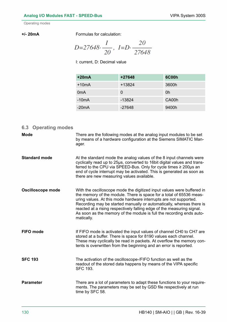
Formulas for calculation:
I: current, D: Decimal value
+20mA +27648 6C00h
+10mA +13824 3600h
0mA 0 0h
-10mA -13824 CA00h
-20mA -27648 9400h
6.3 Operating modesThere are the following modes at the analog input modules to be setby means of a hardware configuration at the Siemens SIMATIC Man-ager.
At the standard mode the analog values of the 8 input channels werecyclically read up to 25µs, converted to 16bit digital values and trans-ferred to the CPU via SPEED-Bus. Only for cycle times ≥ 200µs anend of cycle interrupt may be activated. This is generated as soon asthere are new measuring values available.
With the oscilloscope mode the digitized input values were buffered inthe memory of the module. There is space for a total of 65536 meas-uring values. At this mode hardware interrupts are not supported.Recording may be started manually or automatically, whereas there isreacted at a rising respectively falling edge of the measuring signal.As soon as the memory of the module is full the recording ends auto-matically.
If FIFO mode is activated the input values of channel CH0 to CH7 arestored at a buffer. There is space for 8190 values each channel.These may cyclically be read in packets. At overflow the memory con-tents is overwritten from the beginning and an error is reported.
The activation of the oscilloscope-/FIFO function as well as thereadout of the stored data happens by means of the VIPA specificSFC 193.
There are a lot of parameters to adapt these functions to your require-ments. The parameters may be set by GSD file respectively at runtime by SFC 58.
+/- 20mA
Mode
Standard mode
Oscilloscope mode
FIFO mode
SFC 193
Parameter
VIPA System 300SAnalog I/O Modules FAST - SPEED-Bus
Operating modes
HB140 | SM-AIO | | GB | Rev. 16-39 130
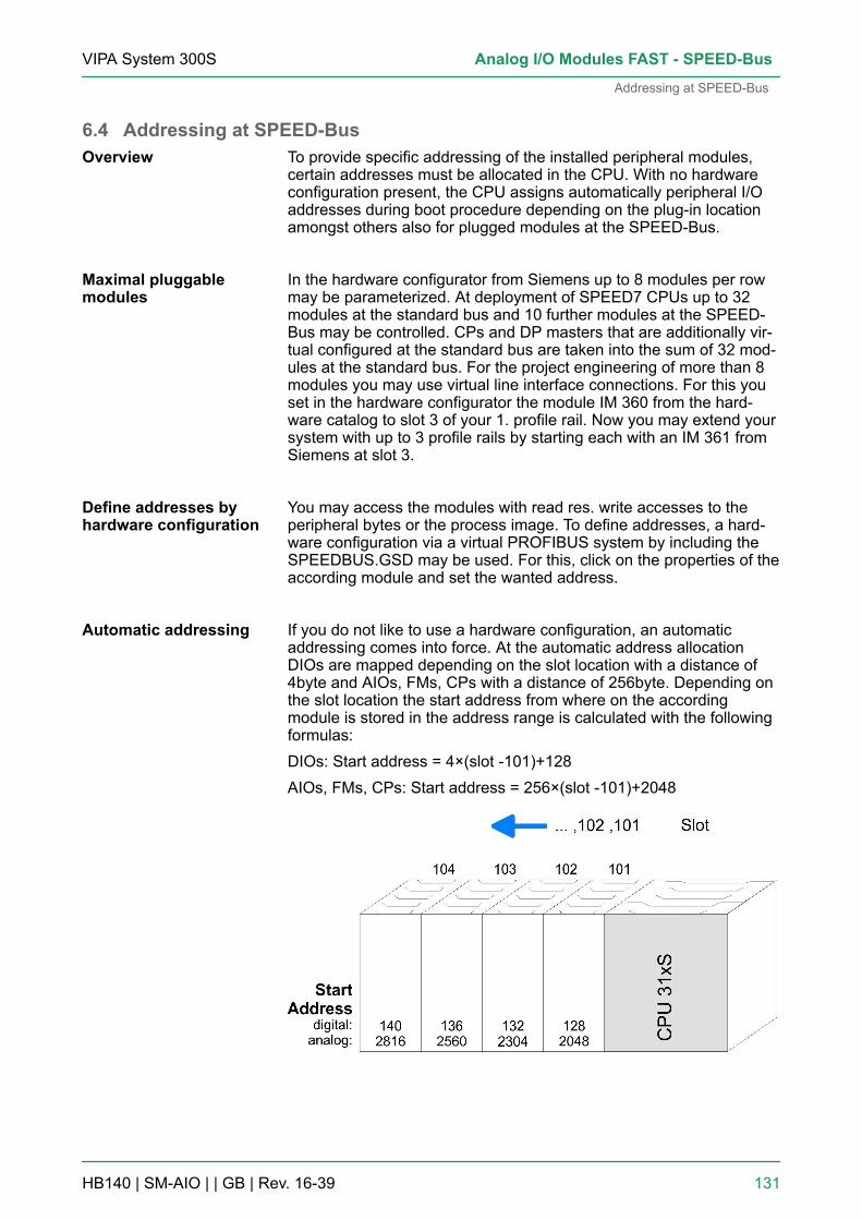
6.4 Addressing at SPEED-BusTo provide specific addressing of the installed peripheral modules,certain addresses must be allocated in the CPU. With no hardwareconfiguration present, the CPU assigns automatically peripheral I/Oaddresses during boot procedure depending on the plug-in locationamongst others also for plugged modules at the SPEED-Bus.
In the hardware configurator from Siemens up to 8 modules per rowmay be parameterized. At deployment of SPEED7 CPUs up to 32modules at the standard bus and 10 further modules at the SPEED-Bus may be controlled. CPs and DP masters that are additionally vir-tual configured at the standard bus are taken into the sum of 32 mod-ules at the standard bus. For the project engineering of more than 8modules you may use virtual line interface connections. For this youset in the hardware configurator the module IM 360 from the hard-ware catalog to slot 3 of your 1. profile rail. Now you may extend yoursystem with up to 3 profile rails by starting each with an IM 361 fromSiemens at slot 3.
You may access the modules with read res. write accesses to theperipheral bytes or the process image. To define addresses, a hard-ware configuration via a virtual PROFIBUS system by including theSPEEDBUS.GSD may be used. For this, click on the properties of theaccording module and set the wanted address.
If you do not like to use a hardware configuration, an automaticaddressing comes into force. At the automatic address allocationDIOs are mapped depending on the slot location with a distance of4byte and AIOs, FMs, CPs with a distance of 256byte. Depending onthe slot location the start address from where on the accordingmodule is stored in the address range is calculated with the followingformulas:DIOs: Start address = 4×(slot -101)+128AIOs, FMs, CPs: Start address = 256×(slot -101)+2048
Overview
Maximal pluggablemodules
Define addresses byhardware configuration
Automatic addressing
VIPA System 300S Analog I/O Modules FAST - SPEED-Bus
Addressing at SPEED-Bus
HB140 | SM-AIO | | GB | Rev. 16-39 131

6.5 Project engineeringEvery module at the SPEED-Bus including the CPU has to be config-ured as single "VIPA_SPEEDBUS" DP slave at a virtual DP master(342-5DA02 V5.0 from Siemens). For this you have to include theSPEEDBUS.GSD. Every "VIPA_SPEEDBUS" DP slave has exactlyone slot for the project engineering where you must place theaccording SPEED-Bus module. The assignment of a SPEED-Busslave to a SPEED-Bus slot number takes place via the PROFIBUSaddress starting with 100.
6.5.1 Fast introductionFor the employment of the I/O modules at the SPEED-Bus the inclu-sion via the GSD-file from VIPA in the hardware catalog is required.To be compatible with the Siemens SIMATIC manager, you have toexecute the following steps:1. Start the hardware configurator from Siemens and include the
SPEEDBUS.GSD for SPEED7 from VIPA.2. Configure the corresponding CPU from Siemens.3. Starting with slot 4, place the System 300 modules in the
plugged sequence.4. Project engineering and connection of the SPEED-Bus-CPs res.
DP master at the standard bus as virtual CP 343-1 (343-1EX11)res. CP 342-5 (342-5DA02 V5.0)
5. For the SPEED-Bus you always include, connect and parame-terize to the operating mode DP master the DP master CP342-5 (342-5DA02 V5.0) as last module. To this master systemyou assign every SPEED-Bus module as VIPA_SPEEDBUSslave. Here the PROFIBUS address corresponds to the slotnumber beginning with 100 for the CPU. Place at slot 0 of everyslave the assigned module and alter the parameters if needed.
6.5.2 PreconditionsThe hardware configurator is part of the Siemens SIMATIC manager.It serves for project engineering. The modules that may be configuredhere are listed in the hardware catalog. For the employment of theSystem 300S modules at the SPEED-Bus you have to include theSystem 300S modules into the hardware catalog via the GSD-fileSPEEDBUS.GSD from VIPA.
For the project engineering, a thorough knowledge ofthe Siemens SIMATIC manager and the hardware con-figurator from Siemens is required!
Overview
VIPA System 300SAnalog I/O Modules FAST - SPEED-Bus
Project engineering > Preconditions
HB140 | SM-AIO | | GB | Rev. 16-39 132

1. Browse to www.vipa.com ‘Service è Downloadè GSD- and EDS-Files è PROFIBUS’ and select the fileCx000023_Vxxx.
2. Extract the file to your work directory. The SPEEDBUS.GSD isstored in the directory System_300S.
3. Start the hardware configurator from Siemens.4. Close all projects.5. Select ‘Options è Install new GSD-file’.6. Change to the directory System_300S and select the
SPEEDBUS.GSD.
ð The modules of the System 300S from VIPA are nowincluded in the hardware catalog at: PROFIBUS DP / Addi-tional field devices / I/O / VIPA_SPEEDBUS.
6.5.3 Steps of project engineeringThe following text describes the approach of the project engineeringin the hardware configurator from Siemens at an abstract sample.The project engineering is separated into following parts:n Project engineering of the modules at the standard busn Project engineering of the SPEED-Bus modules in a virtual master
system (SPEEDBUS.GSD required)
For the employment of the System 300S modules at the SPEED-Busyou have to include the System 300S modules into the hardware cat-alog via the GSD-file SPEEDBUS.GSD from VIPA.
The modules at the right side of the CPU at the standard bus are con-figured with the following approach:1. Start the hardware configurator from Siemens with a new project
and insert a profile rail from the hardware catalog.2. Place the corresponding Siemens CPU at slot 2.
Include the SPEED7-GSD-file
Preconditions
Project engineering ofthe modules at thestandard bus
VIPA System 300S Analog I/O Modules FAST - SPEED-Bus
Project engineering > Steps of project engineering
HB140 | SM-AIO | | GB | Rev. 16-39 133

3. Include your System 300V modules at the standard bus in theplugged sequence starting with slot 4.
4. Parameterize the CPU res. the modules where appropriate. Theparameter window opens by a double click on the accordingmodule.
5. To extend the bus you may use the IM 360 from Siemens whereyou can connect up to 3 further extension racks via the IM 361.Bus extensions are always placed at slot 3.
6. Save your project.
To extend the bus you may use the IM 360 from Sie-mens where you can connect up to 3 further extensionracks via the IM 361. Bus extensions are alwaysplaced at slot 3.
The slot assignment of the SPEED-Bus modules and the parameteri-zation of the in-/output periphery happens via a virtual PROFIBUS DPmaster system. For this, place as last module a DP master(342-5DA02 V5.0) with master system. For the employment of theSystem 300S modules at the SPEED-Bus the inclusion of the System300S modules into the hardware catalog via the GSD-fileSPEEDBUS.GSD from VIPA is required. After the installation of theSPEEDBUS.GSD you may locate under PROFIBUS DP / Additionalfield devices / I/O / VIPA_SPEEDBUS the DP slave systemVIPA_SPEEDBUS. Now include for the CPU and every module at theSPEED-Bus a slave system "VIPA_SPEEDBUS". Set as PROFIBUSaddress the slot no. (100...110) of the module and place theaccording module from the hardware catalog of VIPA_SPEEDBUS toslot 0 of the slave system.
Project engineering ofall SPEED-Bus modulesin a virtual mastersystem
VIPA System 300SAnalog I/O Modules FAST - SPEED-Bus
Project engineering > Steps of project engineering
HB140 | SM-AIO | | GB | Rev. 16-39 134

6.6 ParameterizationAfter PowerON the diagnostics function of every channel is deacti-vated. For parameterization the parameter data of the module aretransferred by the Siemens SIMATIC manager to the CPU. There isalso the possibility to change parameters during run time by means ofSFCs.
1. Start the hardware configurator and install speedbus.gse forSPEED7 from VIPA.
2. Configure the corresponding CPU from Siemens.3. Include your System 300V modules at the standard bus in the
plugged sequence starting with slot 4.4. For the SPEED-Bus you always include, connect and parame-
terize to the operating mode DP master the DP master CP342-5 (342-5DA02 V5.0) as last module.
Overview
Place module
VIPA System 300S Analog I/O Modules FAST - SPEED-Bus
Parameterization
HB140 | SM-AIO | | GB | Rev. 16-39 135

5. To this master system you assign every SPEED-Bus module asVIPA_SPEEDbus slave. Here the PROFIBUS address corre-sponds to the slot number beginning with 100 for the CPU.
6. Place at slot 0 of every slave the assigned module and alter theparameters if needed. In this way also the project engineering ofthe analog modules takes place.
Via double click on the wanted module in the hardware configuratorthe corresponding parameter dialog is opened. You may alter the fol-lowing parameters there:n Start address of the data of the module stored in the CPUn Enable interrupt/Mode (end of cycle, Oscilloscope-/FIFO mode,
diagnostics, limit)n Limit (upper/lower)n Oscilloscope parameter (channel, pre-trigger, level, condition)n Cycle time (scan time at Oscilloscope-/FIFO mode)
n Save and compile your project.n Set your CPU to STOP.n Transfer your project into the CPU.As soon as you switch the CPU into RUN, the parameters are trans-mitted to the analog input module.
6.6.1 Structure of the parameter bytesThe parameterization happens during hardware configuration. Herethe following parameter data are transferred:
Lengthin Byte
Recordset
Description
4 A0h Limit upper/lower channel 0
4 A1h Limit upper/lower channel 1
... ... ...
4 A7h Limit upper/lower channel 7
2 A8h Cycle time/(sampling time at oscilloscope-/FIFO mode)
2 7Fh Interrupt enable/Operating mode
5 BEh Oscilloscope (Parameter for oscilloscopemode)
Using the SFCs 55, 56, 57 and 58 every parameter of the modulemay be transferred to the module during run time. Here the favoriteparameters are transferred as record set by the user program bymeans of SFCs. By this parameters may be transferred, which arenot supported by the Siemens SIMATIC manager.
Parameterize themodule
Save and transferproject
VIPA System 300SAnalog I/O Modules FAST - SPEED-Bus
Parameterization > Structure of the parameter bytes
HB140 | SM-AIO | | GB | Rev. 16-39 136
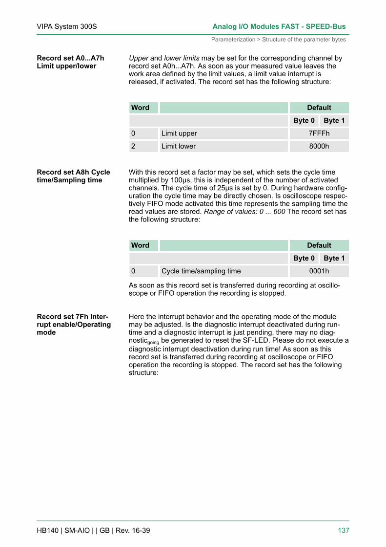
Upper and lower limits may be set for the corresponding channel byrecord set A0h...A7h. As soon as your measured value leaves thework area defined by the limit values, a limit value interrupt isreleased, if activated. The record set has the following structure:
Word Default
Byte 0 Byte 1
0 Limit upper 7FFFh
2 Limit lower 8000h
With this record set a factor may be set, which sets the cycle timemultiplied by 100µs, this is independent of the number of activatedchannels. The cycle time of 25µs is set by 0. During hardware config-uration the cycle time may be directly chosen. Is oscilloscope respec-tively FIFO mode activated this time represents the sampling time theread values are stored. Range of values: 0 ... 600 The record set hasthe following structure:
Word Default
Byte 0 Byte 1
0 Cycle time/sampling time 0001h
As soon as this record set is transferred during recording at oscillo-scope or FIFO operation the recording is stopped.
Here the interrupt behavior and the operating mode of the modulemay be adjusted. Is the diagnostic interrupt deactivated during run-time and a diagnostic interrupt is just pending, there may no diag-nosticgoing be generated to reset the SF-LED. Please do not execute adiagnostic interrupt deactivation during run time! As soon as thisrecord set is transferred during recording at oscilloscope or FIFOoperation the recording is stopped. The record set has the followingstructure:
Record set A0...A7hLimit upper/lower
Record set A8h Cycletime/Sampling time
Record set 7Fh Inter-rupt enable/Operatingmode
VIPA System 300S Analog I/O Modules FAST - SPEED-Bus
Parameterization > Structure of the parameter bytes
HB140 | SM-AIO | | GB | Rev. 16-39 137
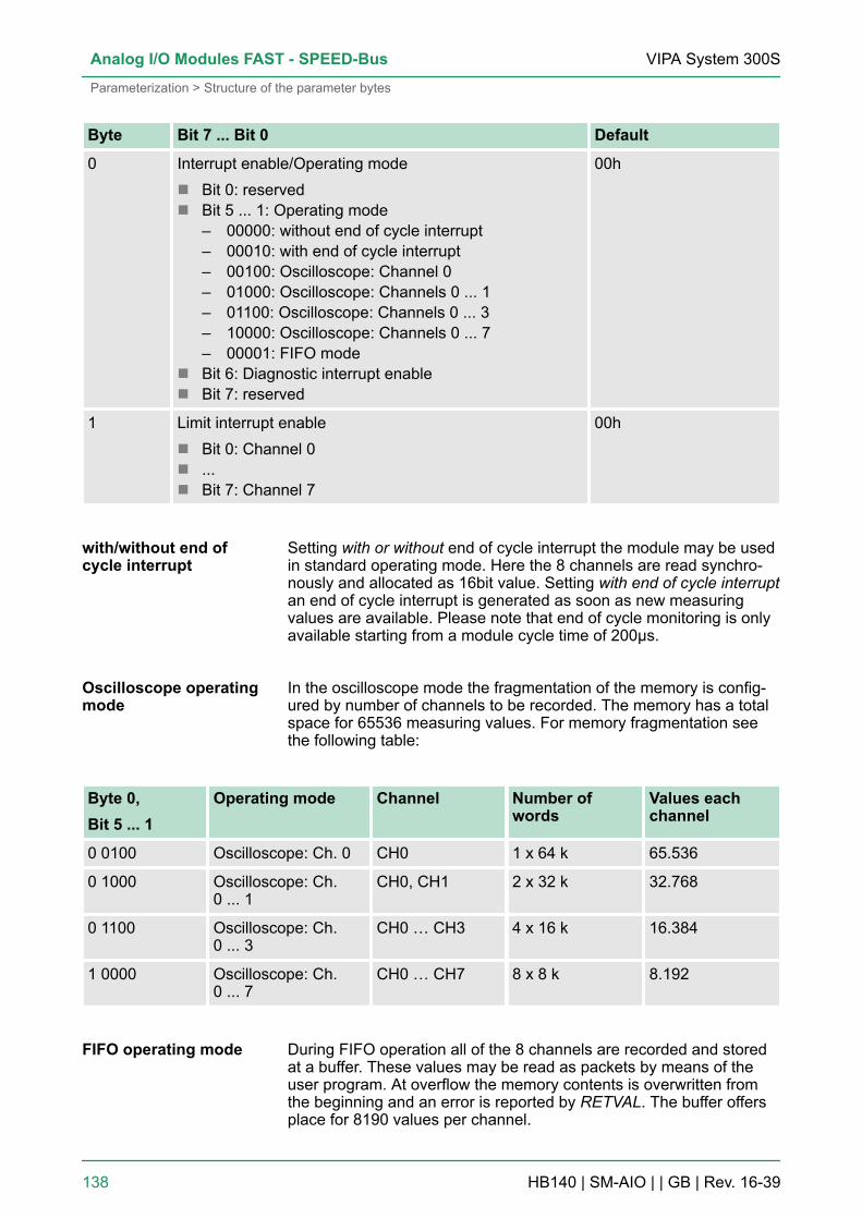
Byte Bit 7 ... Bit 0 Default
0 Interrupt enable/Operating moden Bit 0: reservedn Bit 5 ... 1: Operating mode
– 00000: without end of cycle interrupt– 00010: with end of cycle interrupt– 00100: Oscilloscope: Channel 0– 01000: Oscilloscope: Channels 0 ... 1– 01100: Oscilloscope: Channels 0 ... 3– 10000: Oscilloscope: Channels 0 ... 7– 00001: FIFO mode
n Bit 6: Diagnostic interrupt enablen Bit 7: reserved
00h
1 Limit interrupt enablen Bit 0: Channel 0n ...n Bit 7: Channel 7
00h
Setting with or without end of cycle interrupt the module may be usedin standard operating mode. Here the 8 channels are read synchro-nously and allocated as 16bit value. Setting with end of cycle interruptan end of cycle interrupt is generated as soon as new measuringvalues are available. Please note that end of cycle monitoring is onlyavailable starting from a module cycle time of 200µs.
In the oscilloscope mode the fragmentation of the memory is config-ured by number of channels to be recorded. The memory has a totalspace for 65536 measuring values. For memory fragmentation seethe following table:
Byte 0,Bit 5 ... 1
Operating mode Channel Number ofwords
Values eachchannel
0 0100 Oscilloscope: Ch. 0 CH0 1 x 64 k 65.536
0 1000 Oscilloscope: Ch.0 ... 1
CH0, CH1 2 x 32 k 32.768
0 1100 Oscilloscope: Ch.0 ... 3
CH0 … CH3 4 x 16 k 16.384
1 0000 Oscilloscope: Ch.0 ... 7
CH0 … CH7 8 x 8 k 8.192
During FIFO operation all of the 8 channels are recorded and storedat a buffer. These values may be read as packets by means of theuser program. At overflow the memory contents is overwritten fromthe beginning and an error is reported by RETVAL. The buffer offersplace for 8190 values per channel.
with/without end ofcycle interrupt
Oscilloscope operatingmode
FIFO operating mode
VIPA System 300SAnalog I/O Modules FAST - SPEED-Bus
Parameterization > Structure of the parameter bytes
HB140 | SM-AIO | | GB | Rev. 16-39 138
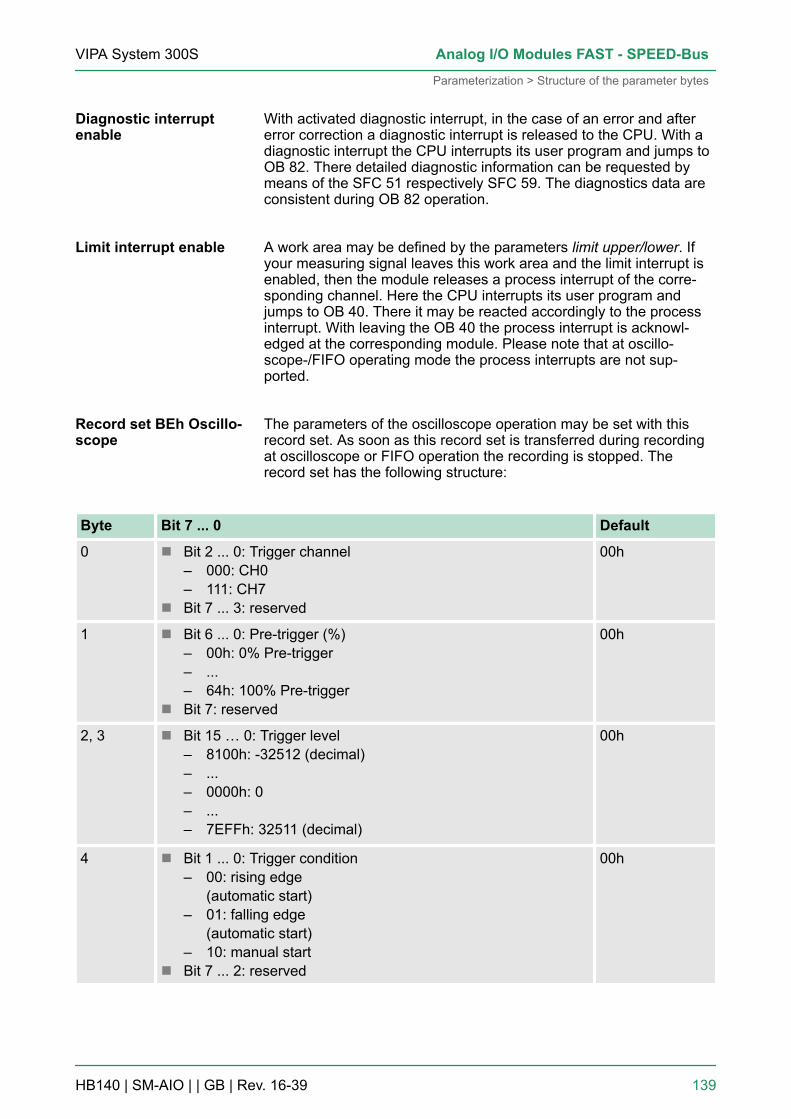
With activated diagnostic interrupt, in the case of an error and aftererror correction a diagnostic interrupt is released to the CPU. With adiagnostic interrupt the CPU interrupts its user program and jumps toOB 82. There detailed diagnostic information can be requested bymeans of the SFC 51 respectively SFC 59. The diagnostics data areconsistent during OB 82 operation.
A work area may be defined by the parameters limit upper/lower. Ifyour measuring signal leaves this work area and the limit interrupt isenabled, then the module releases a process interrupt of the corre-sponding channel. Here the CPU interrupts its user program andjumps to OB 40. There it may be reacted accordingly to the processinterrupt. With leaving the OB 40 the process interrupt is acknowl-edged at the corresponding module. Please note that at oscillo-scope-/FIFO operating mode the process interrupts are not sup-ported.
The parameters of the oscilloscope operation may be set with thisrecord set. As soon as this record set is transferred during recordingat oscilloscope or FIFO operation the recording is stopped. Therecord set has the following structure:
Byte Bit 7 ... 0 Default
0 n Bit 2 ... 0: Trigger channel– 000: CH0– 111: CH7
n Bit 7 ... 3: reserved
00h
1 n Bit 6 ... 0: Pre-trigger (%)– 00h: 0% Pre-trigger– ...– 64h: 100% Pre-trigger
n Bit 7: reserved
00h
2, 3 n Bit 15 … 0: Trigger level– 8100h: -32512 (decimal)– ...– 0000h: 0– ...– 7EFFh: 32511 (decimal)
00h
4 n Bit 1 ... 0: Trigger condition– 00: rising edge
(automatic start)– 01: falling edge
(automatic start)– 10: manual start
n Bit 7 ... 2: reserved
00h
Diagnostic interruptenable
Limit interrupt enable
Record set BEh Oscillo-scope
VIPA System 300S Analog I/O Modules FAST - SPEED-Bus
Parameterization > Structure of the parameter bytes
HB140 | SM-AIO | | GB | Rev. 16-39 139

With this parameter a channel may be defined to be triggered, thismeans the recording is to be started on its rising or falling edge. Atmanual operation this setting will be ignored.
Here a number per cent may be set as pre-trigger. On this way valuesmay also be picked out, which were buffered before the trigger eventoccurred. At manual operation this setting will be ignored. In the fol-lowing there is a formula to calculate the number n of values in thebuffer, which were buffered before the trigger event occurred. Thisvalue depends on the parameters pre-trigger and the number ofchannels to be buffered.
At this parameter a threshold may be set, which when exceeded/fallen below generates a trigger event. At manual operation this set-ting will be ignored.
Here the start condition for recording may be set. To start therecording there is basically differentiated between an automatic oper-ation with a triggered edge and a manual operation.
The oscilloscope/FIFO operation is controlled by means of the SFC193. This is described at the following pages.
6.7 SFC 193 - Oscilloscope-/FIFO functionThe SFC 193 serves for controlling the Oscilloscope-/FIFO function. Itallows to start the recording and to read the buffered data. Dependingupon the parameterization there are the following possibilities:
n Depending on the trigger condition at edge evaluation the moni-toring of the configured channel may be started respectively atmanual operation the recording may be started.
n The recorded measuring values may be accessed by the SFC 193as soon as the buffer is full.
n Start the recordingn Read the puffer at any time
Trigger channel
Pre-trigger (%)
Trigger level
Trigger condition
SFC 193 for controlling
Description
Oscilloscope operation
FIFO operation
VIPA System 300SAnalog I/O Modules FAST - SPEED-Bus
SFC 193 - Oscilloscope-/FIFO function
HB140 | SM-AIO | | GB | Rev. 16-39 140
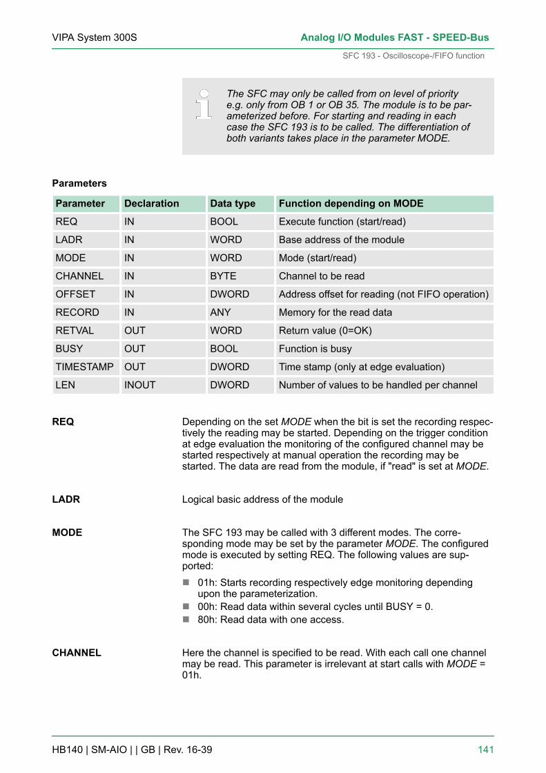
The SFC may only be called from on level of prioritye.g. only from OB 1 or OB 35. The module is to be par-ameterized before. For starting and reading in eachcase the SFC 193 is to be called. The differentiation ofboth variants takes place in the parameter MODE.
Parameters
Parameter Declaration Data type Function depending on MODE
REQ IN BOOL Execute function (start/read)
LADR IN WORD Base address of the module
MODE IN WORD Mode (start/read)
CHANNEL IN BYTE Channel to be read
OFFSET IN DWORD Address offset for reading (not FIFO operation)
RECORD IN ANY Memory for the read data
RETVAL OUT WORD Return value (0=OK)
BUSY OUT BOOL Function is busy
TIMESTAMP OUT DWORD Time stamp (only at edge evaluation)
LEN INOUT DWORD Number of values to be handled per channel
Depending on the set MODE when the bit is set the recording respec-tively the reading may be started. Depending on the trigger conditionat edge evaluation the monitoring of the configured channel may bestarted respectively at manual operation the recording may bestarted. The data are read from the module, if "read" is set at MODE.
Logical basic address of the module
The SFC 193 may be called with 3 different modes. The corre-sponding mode may be set by the parameter MODE. The configuredmode is executed by setting REQ. The following values are sup-ported:n 01h: Starts recording respectively edge monitoring depending
upon the parameterization.n 00h: Read data within several cycles until BUSY = 0.n 80h: Read data with one access.
Here the channel is specified to be read. With each call one channelmay be read. This parameter is irrelevant at start calls with MODE =01h.
REQ
LADR
MODE
CHANNEL
VIPA System 300S Analog I/O Modules FAST - SPEED-Bus
SFC 193 - Oscilloscope-/FIFO function
HB140 | SM-AIO | | GB | Rev. 16-39 141
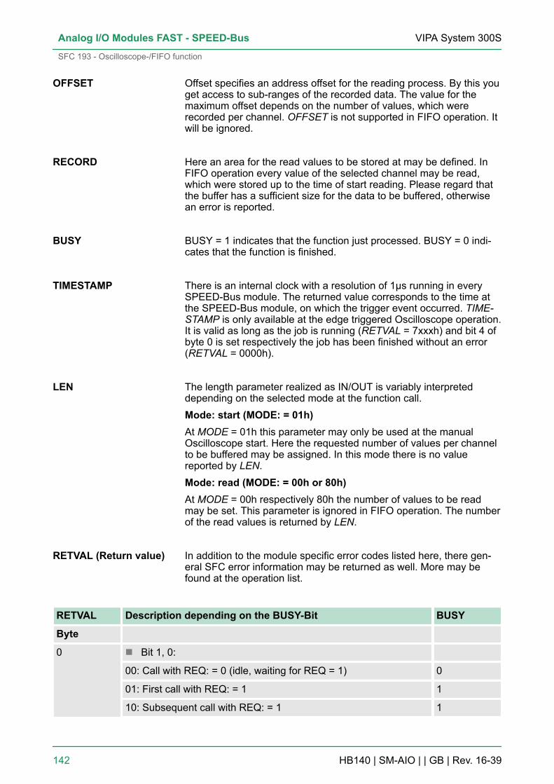
Offset specifies an address offset for the reading process. By this youget access to sub-ranges of the recorded data. The value for themaximum offset depends on the number of values, which wererecorded per channel. OFFSET is not supported in FIFO operation. Itwill be ignored.
Here an area for the read values to be stored at may be defined. InFIFO operation every value of the selected channel may be read,which were stored up to the time of start reading. Please regard thatthe buffer has a sufficient size for the data to be buffered, otherwisean error is reported.
BUSY = 1 indicates that the function just processed. BUSY = 0 indi-cates that the function is finished.
There is an internal clock with a resolution of 1µs running in everySPEED-Bus module. The returned value corresponds to the time atthe SPEED-Bus module, on which the trigger event occurred. TIME-STAMP is only available at the edge triggered Oscilloscope operation.It is valid as long as the job is running (RETVAL = 7xxxh) and bit 4 ofbyte 0 is set respectively the job has been finished without an error(RETVAL = 0000h).
The length parameter realized as IN/OUT is variably interpreteddepending on the selected mode at the function call.Mode: start (MODE: = 01h)At MODE = 01h this parameter may only be used at the manualOscilloscope start. Here the requested number of values per channelto be buffered may be assigned. In this mode there is no valuereported by LEN.Mode: read (MODE: = 00h or 80h)At MODE = 00h respectively 80h the number of values to be readmay be set. This parameter is ignored in FIFO operation. The numberof the read values is returned by LEN.
In addition to the module specific error codes listed here, there gen-eral SFC error information may be returned as well. More may befound at the operation list.
RETVAL Description depending on the BUSY-Bit BUSY
Byte
0 n Bit 1, 0:
00: Call with REQ: = 0 (idle, waiting for REQ = 1) 0
01: First call with REQ: = 1 1
10: Subsequent call with REQ: = 1 1
OFFSET
RECORD
BUSY
TIMESTAMP
LEN
RETVAL (Return value)
VIPA System 300SAnalog I/O Modules FAST - SPEED-Bus
SFC 193 - Oscilloscope-/FIFO function
HB140 | SM-AIO | | GB | Rev. 16-39 142

RETVAL Description depending on the BUSY-Bit BUSY
11: Oscilloscope is just recording. 1
n Bit 2: REQ: = 1, but recording was not yet started.(MODE: = 00h or MODE: = 80h)
0
n Bit 3: reserved -
n Bit 4: Trigger event occurred and recording is just running. 1
n Bit 5: Waiting for trigger event 1
n Bit 7 … 6: reserved -
1 n Bit 0: reserved -
n Bit 1: The number of recorded values exceeds the target areadefined by RECORD (in words).
0
n Bit 2: The number of the recorded values exceeds the areadefined by LEN and OFFSET.
0
n Bit 3: Buffer overflow in FIFO operation. 0
n Bit 7 ... 4:
0000: Job finished without an error 0
0111: Job still running 1
1000: Job finished with error (see following table) 0
Job finished without an error
RETVAL Description depending on the BUSY-Bit BUSY
0000h Job was finished without an error. 0
Job finished with error
RETVAL Description depending on the BUSY-Bit BUSY
8002h: Oscilloscope-/FIFO function is not configured. 0
8003h: An internal error occurred - please contact VIPA. 0
8005h: The selected channel may not be read - wrong channel number. 0
8007h: The value at OFFSET exceeds the number of recorded values. 0
8090h: There is no SPEED-Bus module with this address available. 0
80D2h: LADR exceeds the peripheral address area. 0
VIPA System 300S Analog I/O Modules FAST - SPEED-Bus
SFC 193 - Oscilloscope-/FIFO function
HB140 | SM-AIO | | GB | Rev. 16-39 143

6.8 Example for the Oscilloscope functionAt this example 4 channels were recorded with 25µs sampling timewhereas channel 2 is monitored. As soon as the decimal value 12000is exceeded by the input signal, a trigger event is generated. 50% ofthe buffer should contain the last values before the trigger eventoccurred (pre-trigger) and 50% the values after the event.
The parameterization happens by a hardware configuration of theSiemens SIMATIC manager. Here the integration of the VIPA GSD filespeedbus.gse is necessary. More may be found above at "Projectengineering". Parameterize the following module parameters afterconfiguring the system:Cycle time: 25µsOperating mode: Oscilloscope Channels 0 … 3(16384 values per channel)Oscilloscope trigger channel: 2Oscilloscope pre-trigger (%): 50Oscilloscope trigger level: 12000Oscilloscope trigger condition: rising edge
The SFC 193 calls for starting the oscilloscope recording and forreading the data are implemented in the OB 1 of the user program.For the simplified representation and for controlling the parametersare handled in a variable table.CALL SFC 193 // start oscilloscope function (1. SFC call)
REQ :=M99.0 // bit to start recording
Job definition
Parameterization
User program
VIPA System 300SAnalog I/O Modules FAST - SPEED-Bus
Example for the Oscilloscope function
HB140 | SM-AIO | | GB | Rev. 16-39 144

LADR :=W#16#64 // basic module address
MODE :=W#16#1 // mode: start
CHANNEL :=B#16#0 // not used
OFFSET :=DW#16#0 // not used
RECORD :=DB10 // not used
RETVAL :=MW1110 // return value
BUSY :=M112.0 // busy bit
TIMESTAMP:=MD100 // not used
LEN :=MD114 // length parameter for recording
// (only at "manual start")U M 99.0 // request bit set by 1. call?
S M 98.1 // yes: set request bit for 2. call
R M 99.0 // Reset request bit for 1. call
CALL SFC 193 // read data (2. SFC call)
REQ :=M98.1 // bit for reading the data
LADR :=W#16#64 // basic module address
MODE :=W#16#80 // mode: read (complete, 1 access)
CHANNEL :=MB148 // channel to be read
OFFSET :=MD150 // address offset for reading
RECORD :=DB10 // data block for the read values
RETVAL :=MW110 // return value
BUSY :=M112.0 // busy bit
TIMESTAMP:=MD104 // timestamp at trigger event
LEN :=MD114 // length parameter for reading
U M 98.1 // request bit set and
U M 112.0 // busy bit set?
BEB // yes: reading is not yet finished; finish block
U M 98.1 // request bit is set and
UN M 112.0 // busy bit is not set?
SPBN end // no: jump to label end
L MW 110 // yes: load return value and
T MW 160 // transfer to flagend: NOP 0U M 98.1R M 98.1 // reset request bit from 2. call
VIPA System 300S Analog I/O Modules FAST - SPEED-Bus
Example for the Oscilloscope function
HB140 | SM-AIO | | GB | Rev. 16-39 145
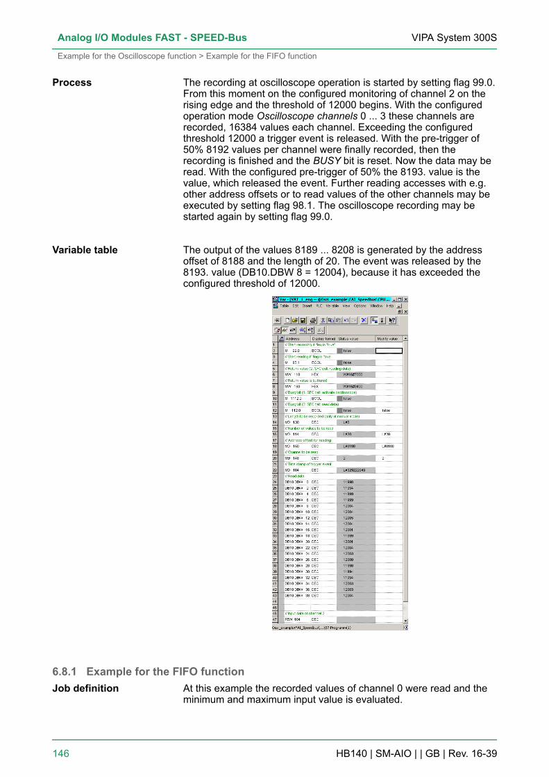
The recording at oscilloscope operation is started by setting flag 99.0.From this moment on the configured monitoring of channel 2 on therising edge and the threshold of 12000 begins. With the configuredoperation mode Oscilloscope channels 0 ... 3 these channels arerecorded, 16384 values each channel. Exceeding the configuredthreshold 12000 a trigger event is released. With the pre-trigger of50% 8192 values per channel were finally recorded, then therecording is finished and the BUSY bit is reset. Now the data may beread. With the configured pre-trigger of 50% the 8193. value is thevalue, which released the event. Further reading accesses with e.g.other address offsets or to read values of the other channels may beexecuted by setting flag 98.1. The oscilloscope recording may bestarted again by setting flag 99.0.
The output of the values 8189 ... 8208 is generated by the addressoffset of 8188 and the length of 20. The event was released by the8193. value (DB10.DBW 8 = 12004), because it has exceeded theconfigured threshold of 12000.
6.8.1 Example for the FIFO functionAt this example the recorded values of channel 0 were read and theminimum and maximum input value is evaluated.
Process
Variable table
Job definition
VIPA System 300SAnalog I/O Modules FAST - SPEED-Bus
Example for the Oscilloscope function > Example for the FIFO function
HB140 | SM-AIO | | GB | Rev. 16-39 146
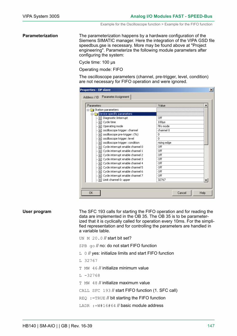
The parameterization happens by a hardware configuration of theSiemens SIMATIC manager. Here the integration of the VIPA GSD filespeedbus.gse is necessary. More may be found above at "Projectengineering". Parameterize the following module parameters afterconfiguring the system:Cycle time: 100 µsOperating mode: FIFOThe oscilloscope parameters (channel, pre-trigger, level, condition)are not necessary for FIFO operation and were ignored.
The SFC 193 calls for starting the FIFO operation and for reading thedata are implemented in the OB 35. The OB 35 is to be parameter-ized that it is cyclically called for operation every 10ms. For the simpli-fied representation and for controlling the parameters are handled ina variable table.UN M 20.0 // start bit set?
SPB go // no: do not start FIFO function
L 0 // yes: initialize limits and start FIFO functionL 32767T MW 46 // initialize minimum valueL -32768T MW 48 // initialize maximum value
CALL SFC 193 // start FIFO function (1. SFC call)
REQ :=TRUE // bit starting the FIFO function
LADR :=W#16#64 // basic module address
Parameterization
User program
VIPA System 300S Analog I/O Modules FAST - SPEED-Bus
Example for the Oscilloscope function > Example for the FIFO function
HB140 | SM-AIO | | GB | Rev. 16-39 147

MODE :=W#16#1 // mode: start
CHANNEL :=B#16#0 // not used
OFFSET :=DW#16#0 // not used
RECORD :=DB1 // not used
RETVAL :=MW22 // return value
BUSY :=M20.1 // busy bit
TIMESTAMP:=MD24 // not used
LEN :=MD28 // not used
U M 20.0 // reset start bitR M 20.0S M 20.2 // start reading if FIFO active
go: UN M 20.2 // bit set for reading?
BEB // no: finish block
CALL SFC 193 // read data (2. SFC call)
REQ :=TRUE // bit for reading the data
LADR :=W#16#64 // basic module address
MODE :=W#16#80 // mode: read (complete, 1 access)
CHANNEL :=MB21 // channel to be read
OFFSET :=DW#16#0 // not used
RECORD :=DB1 // data block for the read values
RETVAL :=MW32 // return value
BUSY :=M20.3 // busy bit
TIMESTAMP:=MD34 // not used
LEN :=MD38 // length parameter for reading
L MD 38 // load length parameterL 0==D // check if values were read
BEB // no: finish block
// every value in the buffer was read// and stored in DB 1L P#0.0 // set pointer to the 1. value of DB 1
T MD 42 // store pointer in flag
AUF DB 1 // open DB 1
// Check for new minimum:loop: L DBW [MD 42 // load input value from DB
L MW 46 // load previous minimum value
>=I // is the input value exceeding // the previous minimum?
VIPA System 300SAnalog I/O Modules FAST - SPEED-Bus
Example for the Oscilloscope function > Example for the FIFO function
HB140 | SM-AIO | | GB | Rev. 16-39 148
SPB max // yes: check for maximum
TAK // no: exchange accu1 and accu2 - then the measuring value isin // accu1 againT MW 46 // store new minimum in flag //Check for a new maximum:
max: L DBW [MD 42] // load input value from DB
L MW 48 // load previous maximum
<=I // is the input value less the
// previous maximum?SPB ex // yes: next value
TAK // no: exchange accu1 and accu2 -
// then the measuring value is in accu1 againT MW 48 // store new maximum in flag
ex: NOP 0 // Set pointer to the next value in DB 1:
L MD 42 // load pointer from flag
L P#2.0 // 2bytes because the input values were // stored as wordsin the DB 1+D // increment pointer
T MD 42 // store pointer in flag
// Compare pointer with length of read data:SRD 4L MD 38 // number of read values
<D // Does the pointer point to a valid field
// in the DB 1?SPB loop // yes: check next value
The recording at FIFO operation is started by setting flag 20.0. Fromthis moment on the whole buffered input values of channel 0 wereevery 10ms cyclically read and stored in the data block. The evalua-tion for minimum and maximum is executed in a loop. Here thenumber of read values and so the number of necessary loop opera-tions is represented by the parameter LEN. After evaluation of thewhole read data the OB 35 is finished.
The recording at FIFO operation is started by setting flag 20.0. Thecyclic read access is indicated by flag 20.2. The channel to be readmay be defined by flag 21. At a cyclic read access every 10ms and asample time of 100µs about 100 values may be read from the buffer.The number of read values is reported in flag 38. The minimumrespectively maximum value may be found in the flag word 46respectively 48.
Process
Variable table
VIPA System 300S Analog I/O Modules FAST - SPEED-Bus
Example for the Oscilloscope function > Example for the FIFO function
HB140 | SM-AIO | | GB | Rev. 16-39 149

6.9 DiagnosticsA diagnostic is an error message to a superordinated system (CPU).If enabled by parameterization the following events can release adiagnostic interrupt:n Error in parameterizationn Process interrupt lostn Measuring range over-/underflown External power supply is missingAt a diagnostic interrupt the CPU interrupts the user application andjumps to the OB 82. Within this OB you can accordingly react to therequested diagnostics information of the module. In the case of anerror diagnosticcoming and with correction diagnosticgoing is released.
Overview
VIPA System 300SAnalog I/O Modules FAST - SPEED-Bus
Diagnostics
HB140 | SM-AIO | | GB | Rev. 16-39 150
The module sends the measuring value 7FFFh at overflow, when rec-ognizing a parameterization error or power supply is missing and8000h at underflow. The group error LED (SF) indicates an error, ifthe diagnostics interrupt is activated.
At a diagnostics event the CPU interrupts the user program andjumps into the OB 82. This OB allows you via according programmingto request detailed diagnostic information with record set 0 and 1 bymeans of the SFCs 51 and 59 and react to it. After processing of theOB 82, the processing of the user application is continued. The diag-nostic data are consistent until leaving the OB 82. As soon as youhave enabled the diagnostic interrupt, record set 0 is transferred tothe superordinated system in cause of an error. The record set 0 hasa fixed content and a length of 4byte. The content of record set 0 maybe monitored in plain text in the diagnosis window of the CPU. Forextended diagnostics during run time, you may also evaluate therecord set 1 of 16byte length via SFCs 51 and 59. Record set 0 and 1have the following structure:
Record set 0 (Byte 0 ... 3):
Byte Bit 7 ... Bit 0 Default
0 n Bit 0: Error in modulen Bit 1: Internal errorn Bit 2: External errorn Bit 3: Channel errorn Bit 4: External power supply is missingn Bit 6, 5: reservedn Bit 7: Wrong parameters in module
00h
1 n Bit 3 ... 0: Module class– 0101 Analog module
n Bit 4: Channel information presentn Bit 7 ... 5: reserved
15h
2 reserved 00h
3 n Bit 5 ... 0: reservedn Bit 6: Process interrupt lostn Bit 7: reserved
00h
Byte 0 ... 15: The record set 1 contains the 4byte of record set 0 andadditionally 12byte module specific diagnostic data. The diagnosticbytes have the following assignment:
Error indication viameasuring value andLEDs
Evaluating the diagnos-tics
Diagnostics record set0
Diagnostics record set1
VIPA System 300S Analog I/O Modules FAST - SPEED-Bus
Diagnostics
HB140 | SM-AIO | | GB | Rev. 16-39 151

Record set 1 (Byte 0 ... 15):
Byte Bit 7 ... Bit 0 Default
0 ... 3 Content record set 0 Ä ‘Diagnostics record set 0’ on page 151 -
4 n Bit 6 ... 0: Channel type– 70h: Digital input– 71h: Analog input– 72h: Digital output– 73h: Analog output– 74h: Analog in-/output
n Bit 7: More channel types present– 0: no– 1: yes
71h
5 n Bit 7 ... 0: Number of diagnostic bits, that the module throwsper channel
08h
6 n Bit 7 ... 0: Number of similar channels of a module 08h
7 n Bit 0: Channel error Channel 0n ...n Bit 7: Channel error Channel 7
00h
8 n Bit 0: Project engineering/Parameterization error Channel 0n Bit 5 ... 1: reservedn Bit 6: Underflow Channel 0n Bit 7: Overflow Channel 0
00h
... ...
15 n Bit 0: Project engineering/Parameterization error Channel 7n Bit 5 ... 1: reservedn Bit 6: Underflow Channel 7n Bit 7: Overflow Channel 7
00h
6.9.1 Process interruptsWhen a process interrupt occurs, the CPU interrupts the user applica-tion and jumps to OB 40. Within the OB 40 there is the possibility toget the basic address of the module, which released the processinterrupt by means of the local word 6. At the operation mode oscillo-scope-/FIFO the process interrupts are deactivated.
The following releases for a process interrupt may be defined duringparameterization:n Limit overflown Limit underflown End of cycle as soon as measuring value conversion of every
channel has finished.
Activator
VIPA System 300SAnalog I/O Modules FAST - SPEED-Bus
Diagnostics > Process interrupts
HB140 | SM-AIO | | GB | Rev. 16-39 152
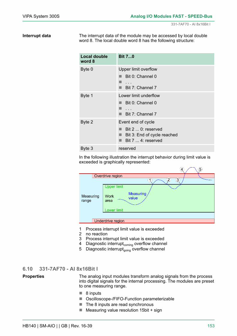
The interrupt data of the module may be accessed by local doubleword 8. The local double word 8 has the following structure:
Local doubleword 8
Bit 7...0
Byte 0 Upper limit overflown Bit 0: Channel 0n . . .n Bit 7: Channel 7
Byte 1 Lower limit underflown Bit 0: Channel 0n . . .n Bit 7: Channel 7
Byte 2 Event end of cyclen Bit 2 ... 0: reservedn Bit 3: End of cycle reachedn Bit 7 ... 4: reserved
Byte 3 reserved
In the following illustration the interrupt behavior during limit value isexceeded is graphically represented:
1 Process interrupt limit value is exceeded2 no reaction3 Process interrupt limit value is exceeded4 Diagnostic interruptcoming overflow channel5 Diagnostic interruptgoing overflow channel
6.10 331-7AF70 - AI 8x16Bit IThe analog input modules transform analog signals from the processinto digital signals for the internal processing. The modules are presetto one measuring range.n 8 inputsn Oscilloscope-/FIFO-Function parameterizablen The 8 inputs are read synchronousn Measuring value resolution 15bit + sign
Interrupt data
Properties
VIPA System 300S Analog I/O Modules FAST - SPEED-Bus
331-7AF70 - AI 8x16Bit I
HB140 | SM-AIO | | GB | Rev. 16-39 153
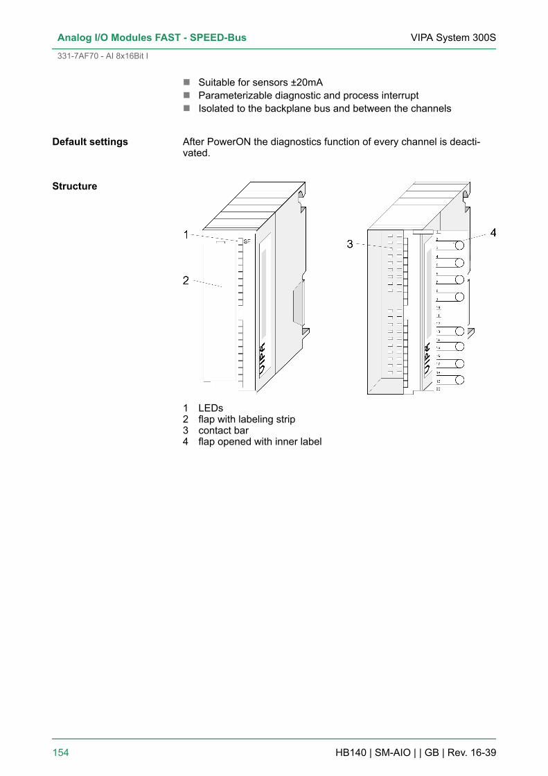
n Suitable for sensors ±20mAn Parameterizable diagnostic and process interruptn Isolated to the backplane bus and between the channels
After PowerON the diagnostics function of every channel is deacti-vated.
1 LEDs2 flap with labeling strip3 contact bar4 flap opened with inner label
Default settings
Structure
VIPA System 300SAnalog I/O Modules FAST - SPEED-Bus
331-7AF70 - AI 8x16Bit I
HB140 | SM-AIO | | GB | Rev. 16-39 154
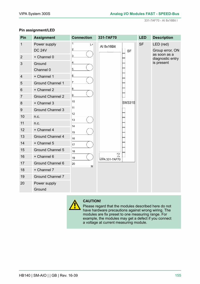
Pin assignment/LED
Pin Assignment Connection 331-7AF70 LED Description
1 Power supplyDC 24V
SF LED (red)Group error, ONas soon as adiagnostic entryis present
2 + Channel 0
3 GroundChannel 0
4 + Channel 1
5 Ground Channel 1
6 + Channel 2
7 Ground Channel 2
8 + Channel 3
9 Ground Channel 3
10 n.c.
11 n.c.
12 + Channel 4
13 Ground Channel 4
14 + Channel 5
15 Ground Channel 5
16 + Channel 6
17 Ground Channel 6
18 + Channel 7
19 Ground Channel 7
20 Power supplyGround
CAUTION!Please regard that the modules described here do nothave hardware precautions against wrong wiring. Themodules are fix preset to one measuring range. Forexample, the modules may get a defect if you connecta voltage at current measuring module.
VIPA System 300S Analog I/O Modules FAST - SPEED-Bus
331-7AF70 - AI 8x16Bit I
HB140 | SM-AIO | | GB | Rev. 16-39 155

6.10.1 Technical data
Order no. 331-7AF70
Type SM 331S - SPEED-Bus
SPEED-Bus ü
Current consumption/power loss
Current consumption from backplane bus 530 mA
Power loss 4 W
Technical data analog inputs
Number of inputs 8
Cable length, shielded 50 m
Rated load voltage DC 24 V
Current consumption from load voltage L+(without load)
62 mA
Voltage inputs -
Min. input resistance (voltage range) -
Input voltage ranges -
Operational limit of voltage ranges -
Operational limit of voltage ranges with SFU -
Basic error limit voltage ranges -
Basic error limit voltage ranges with SFU -
Destruction limit voltage -
Current inputs ü
Max. input resistance (current range) 100 Ω
Input current ranges -20 mA ... +20 mA
Operational limit of current ranges +/-0.6%
Operational limit of current ranges with SFU -
Grundfehlergrenze Strombereiche +/-0.4%
Radical error limit current ranges with SFU -
Destruction limit current inputs (electrical cur-rent)
max. 40mA
Destruction limit current inputs (voltage) max. 30V
Resistance inputs -
Resistance ranges -
Operational limit of resistor ranges -
Operational limit of resistor ranges with SFU -
Basic error limit -
VIPA System 300SAnalog I/O Modules FAST - SPEED-Bus
331-7AF70 - AI 8x16Bit I > Technical data
HB140 | SM-AIO | | GB | Rev. 16-39 156

Order no. 331-7AF70
Basic error limit with SFU -
Destruction limit resistance inputs -
Resistance thermometer inputs -
Resistance thermometer ranges -
Operational limit of resistance thermometerranges
-
Operational limit of resistance thermometerranges with SFU
-
Basic error limit thermoresistor ranges -
Basic error limit thermoresistor ranges withSFU
-
Destruction limit resistance thermometer inputs -
Thermocouple inputs -
Thermocouple ranges -
Operational limit of thermocouple ranges -
Operational limit of thermocouple ranges withSFU
-
Basic error limit thermoelement ranges -
Basic error limit thermoelement ranges withSFU
-
Destruction limit thermocouple inputs -
Programmable temperature compensation -
External temperature compensation -
Internal temperature compensation -
Temperature error internal compensation -
Technical unit of temperature measurement -
Resolution in bit 16
Measurement principle successive approximation
Basic conversion time 25 µs all channels
Noise suppression for frequency -
Initial data size 16 Byte
Status information, alarms, diagnostics
Status display none
Interrupts yes
Process alarm yes, parameterizable
Diagnostic interrupt yes, parameterizable
VIPA System 300S Analog I/O Modules FAST - SPEED-Bus
331-7AF70 - AI 8x16Bit I > Technical data
HB140 | SM-AIO | | GB | Rev. 16-39 157

Order no. 331-7AF70
Diagnostic functions yes
Diagnostics information read-out possible
Supply voltage display none
Group error display red SF LED
Channel error display none
Isolation
Between channels ü
Between channels of groups to 1
Between channels and backplane bus ü
Between channels and power supply ü
Max. potential difference between circuits -
Max. potential difference between inputs (Ucm) DC 30 V
Max. potential difference between Mana andMintern (Uiso)
-
Max. potential difference between inputs andMana (Ucm)
-
Max. potential difference between inputs andMintern (Uiso)
DC 75 V/ AC 50 V
Max. potential difference between Mintern andoutputs
-
Insulation tested with DC 500 V
Datasizes
Input bytes 16
Output bytes 0
Parameter bytes 41
Diagnostic bytes 16
Housing
Material PPE
Mounting DIN rail SPEED-Bus
Mechanical data
Dimensions (WxHxD) 40 mm x 125 mm x 120 mm
Weight 210 g
Environmental conditions
Operating temperature 0 °C to 60 °C
Storage temperature -25 °C to 70 °C
VIPA System 300SAnalog I/O Modules FAST - SPEED-Bus
331-7AF70 - AI 8x16Bit I > Technical data
HB140 | SM-AIO | | GB | Rev. 16-39 158

Order no. 331-7AF70
Certifications
UL certification yes
KC certification -
Additional Technical data
Order number 331-7AF70
Suppression of interference, Limits of error
Noise suppression for f=nx (f1±1%)(f1=Interference frequency, n=1,2,...)- Common-mode interference (UCM<?V)
(UCM<20V) >80dB
Crosstalk between the inputs >50dB
Temperature error (reference to the inputrange)
±0.0150%/K
Linearity error (with reference to the inputrange)
±0.02%
Repeatability (in steady state at 25°C, refer-ence to the input range)
±0.05%
Data for selecting a sensor
Maximum input current for current input(destruction limit)
max. 40mA
Connection of the sensor- for measuring current 2-wire transmitter
possible
6.11 331-7BF70 - AI 8x16Bit UThe analog input modules transform analog signals from the processinto digital signals for the internal processing. The modules are presetto one measuring range.n 8 inputsn Oscilloscope-/FIFO-Function parameterizablen The 8 inputs are read synchronousn Measuring value resolution 15bit + signn Suitable for sensors ±10Vn Parameterizable diagnostic and process interruptn Isolated to the backplane bus and between the channels
After PowerON the diagnostics function of every channel is deacti-vated.
Properties
Default settings
VIPA System 300S Analog I/O Modules FAST - SPEED-Bus
331-7BF70 - AI 8x16Bit U
HB140 | SM-AIO | | GB | Rev. 16-39 159

1 LEDs2 flap with labeling strip3 contact bar4 flap opened with inner label
Structure
VIPA System 300SAnalog I/O Modules FAST - SPEED-Bus
331-7BF70 - AI 8x16Bit U
HB140 | SM-AIO | | GB | Rev. 16-39 160

Pin assignment/LED
Pin Assignment Connection 331-7BF70 LED Description
1 Power supplyDC 24V
SF LED (red)Group error,ON as soon asa diagnosticentry is present
2 + Channel 0
3 Ground Channel 0
4 + Channel 1
5 Ground Channel 1
6 + Channel 2
7 Ground Channel 2
8 + Channel 3
9 Ground Channel 3
10 n.c.
11 n.c.
12 + Channel 4
13 Ground Channel 4
14 + Channel 5
15 Ground Channel 5
16 + Channel 6
17 Ground Channel 6
18 +Channel 7
19 Ground Channel 7
20 Power supplyGround
CAUTION!Please regard that the modules described here do nothave hardware precautions against wrong wiring. Themodules are fix preset to one measuring range. Forexample, the modules may get a defect if you connecta voltage at current measuring module.
6.11.1 Technical data
Order no. 331-7BF70
Type SM 331S - SPEED-Bus
SPEED-Bus ü
VIPA System 300S Analog I/O Modules FAST - SPEED-Bus
331-7BF70 - AI 8x16Bit U > Technical data
HB140 | SM-AIO | | GB | Rev. 16-39 161
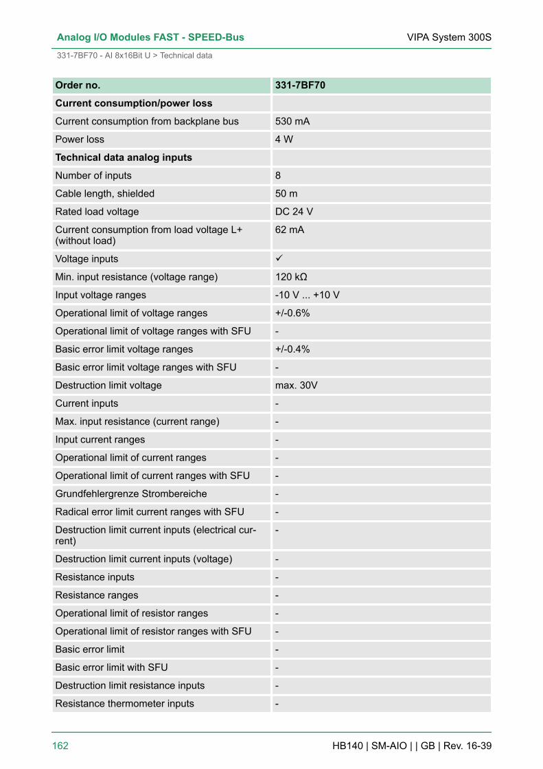
Order no. 331-7BF70
Current consumption/power loss
Current consumption from backplane bus 530 mA
Power loss 4 W
Technical data analog inputs
Number of inputs 8
Cable length, shielded 50 m
Rated load voltage DC 24 V
Current consumption from load voltage L+(without load)
62 mA
Voltage inputs ü
Min. input resistance (voltage range) 120 kΩ
Input voltage ranges -10 V ... +10 V
Operational limit of voltage ranges +/-0.6%
Operational limit of voltage ranges with SFU -
Basic error limit voltage ranges +/-0.4%
Basic error limit voltage ranges with SFU -
Destruction limit voltage max. 30V
Current inputs -
Max. input resistance (current range) -
Input current ranges -
Operational limit of current ranges -
Operational limit of current ranges with SFU -
Grundfehlergrenze Strombereiche -
Radical error limit current ranges with SFU -
Destruction limit current inputs (electrical cur-rent)
-
Destruction limit current inputs (voltage) -
Resistance inputs -
Resistance ranges -
Operational limit of resistor ranges -
Operational limit of resistor ranges with SFU -
Basic error limit -
Basic error limit with SFU -
Destruction limit resistance inputs -
Resistance thermometer inputs -
VIPA System 300SAnalog I/O Modules FAST - SPEED-Bus
331-7BF70 - AI 8x16Bit U > Technical data
HB140 | SM-AIO | | GB | Rev. 16-39 162

Order no. 331-7BF70
Resistance thermometer ranges -
Operational limit of resistance thermometerranges
-
Operational limit of resistance thermometerranges with SFU
-
Basic error limit thermoresistor ranges -
Basic error limit thermoresistor ranges withSFU
-
Destruction limit resistance thermometer inputs -
Thermocouple inputs -
Thermocouple ranges -
Operational limit of thermocouple ranges -
Operational limit of thermocouple ranges withSFU
-
Basic error limit thermoelement ranges -
Basic error limit thermoelement ranges withSFU
-
Destruction limit thermocouple inputs -
Programmable temperature compensation -
External temperature compensation -
Internal temperature compensation -
Temperature error internal compensation -
Technical unit of temperature measurement -
Resolution in bit 16
Measurement principle successive approximation
Basic conversion time 25 µs all channels
Noise suppression for frequency -
Initial data size 16 Byte
Status information, alarms, diagnostics
Status display none
Interrupts yes
Process alarm yes, parameterizable
Diagnostic interrupt yes, parameterizable
Diagnostic functions yes
Diagnostics information read-out possible
Supply voltage display none
VIPA System 300S Analog I/O Modules FAST - SPEED-Bus
331-7BF70 - AI 8x16Bit U > Technical data
HB140 | SM-AIO | | GB | Rev. 16-39 163

Order no. 331-7BF70
Group error display red SF LED
Channel error display none
Isolation
Between channels ü
Between channels of groups to 1
Between channels and backplane bus ü
Between channels and power supply ü
Max. potential difference between circuits -
Max. potential difference between inputs (Ucm) DC 30 V
Max. potential difference between Mana andMintern (Uiso)
-
Max. potential difference between inputs andMana (Ucm)
-
Max. potential difference between inputs andMintern (Uiso)
DC 75 V/ AC 50 V
Max. potential difference between Mintern andoutputs
-
Insulation tested with DC 500 V
Datasizes
Input bytes 16
Output bytes 0
Parameter bytes 41
Diagnostic bytes 16
Housing
Material PPE
Mounting DIN rail SPEED-Bus
Mechanical data
Dimensions (WxHxD) 40 mm x 125 mm x 120 mm
Weight 210 g
Environmental conditions
Operating temperature 0 °C to 60 °C
Storage temperature -25 °C to 70 °C
Certifications
UL certification yes
KC certification -
VIPA System 300SAnalog I/O Modules FAST - SPEED-Bus
331-7BF70 - AI 8x16Bit U > Technical data
HB140 | SM-AIO | | GB | Rev. 16-39 164

Additional Technical data
Order number 331-7BF70
Suppression of interference, Limits of error
Noise suppression for f=nx (f1±1%)(f1=Interference frequency, n=1,2,...)- Common-mode interference (UCM< ?V)
(UCM<20V) >80dB
Crosstalk between the inputs >50dB
Temperature error (reference to the input range) ±0.0150%/K
Linearity error (with reference to the input range) ±0.02%
Repeatability (in steady state at 25°C, referenceto the input range)
±0.05%
Data for selecting a sensor
Maximum input current for current input(destruction limit)
-
Maximum input voltage for voltage input(destruction limit)
max. 30V
Connection of the sensor- for measuring voltage
possible
VIPA System 300S Analog I/O Modules FAST - SPEED-Bus
331-7BF70 - AI 8x16Bit U > Technical data
HB140 | SM-AIO | | GB | Rev. 16-39 165