members.igu.orgmembers.igu.org/old/history/previous-committees/copy_of... · Web viewThe NACE...
77
Working Committee 3 – Gas Transmission Study Group 3.2 2009-2012 Triennium Report Integrity Threats, Influence of Stakeholders & Environmental Footprint
Transcript of members.igu.orgmembers.igu.org/old/history/previous-committees/copy_of... · Web viewThe NACE...

Working Committee 3 – Gas TransmissionStudy Group 3.2
2009-2012 Triennium ReportIntegrity Threats, Influence of Stakeholders & Environmental
Footprint

Table of Content1.0 Executive Summary2.0 Background
2.1 Scope and Purpose2.2 Methodology 2.3 Respondents
3.0 Pipeline Integrity Threats and Its Mitigations3.1 Evaluation and Discussion of Questionnaires3.2 Best Practices, New Technologies and Lessons Learnt
3.2.1 Integrity Management, Codes and Procedures3.2.1.1 PETRONAS’ Pipeline Integrity Management Standard3.2.1.2 The E.ON Ruhrgas / Open Grid Europe Approach towards
Pipeline Integrity Management3.2.1.3 United Kingdom’s PAS 553.2.1.4 French safety studies for integrity assessment3.2.1.5 Swissgas’ Guidelines for Risk Assessment3.2.1.6 Leading and Lagging Key Performance Indicators (KPIs) for
Pipeline Integrity Management3.2.1.7 PETRONAS’ Technical Development Framework3.2.1.8 Effects of Human and Organization on Pipeline Integrity
3.2.2 Incident Databases and Public Communication3.2.2.1 EGIG’s Pipeline Incident Guideline3.2.2.2 UKOPA’s Pipeline Products Loss Incident Report3.2.2.3 Australian Pipeline Industry Association’s (APIA) Pipeline
Incident Report3.2.2.4 Public Communication Guidelines for Emergency3.2.2.5 UK’s PARLOC Database
3.2.3 Specific Integrity Threats3.2.3.1 Third party interference
3.2.3.1.1 E.ON Ruhrgas / Open Grid Europe’s Detection of Third Party Impact by Remote Potential Monitoring
3.2.3.1.2 GRTgaz approach to improve pipeline survey3.2.3.1.3 PETRONAS’ S100 Unmanned Aerial Vehicle
Technology3.2.3.2 Stress Corrosion Cracking
3.2.3.2.1 TGS’ Stress Corrosion Cracking Mitigating Practices
3.2.3.2.2 Spetneftegaz’s In-line Inspection Tool for SCC3.2.3.3 Girth weld defects
3.2.3.3.1 Spetneftegaz’s In-line Inspection Tool for Girth Weld Defects
3.2.3.3.2 Automated Ultrasonic Testing (AUT)3.2.3.4 External and Internal Corrosion
[3.2.3.4.1] Process to Ddetect Ccritical Zzones caused by External Corrosion

3.2.3.4.1[3.2.3.4.2] NACE Standards on Corrosion Management
3.3 Summary
4.0 Influence of Stakeholders in Pipeline Safety and Environmental Regulations4.1 Evaluation and Discussion
4.1.1 National Authorities: Safety and Environmental Regulation4.1.2 Public, Mass Media and other Stakeholder
4.2 Best Practices, New Technologies and Lessons Learnt4.3 Summary
5.0 Environmental Footprint Reduction and Mitigations5.1 Evaluation and Discussion5.2 Best Practices, New Technologies and Lessons Learnt
5.1.1 New technologies for leak detection5.1.1.1 Tightness Checks on Gas Facilities and Above-ground Piping
Components with GasCam5.1.1.2 Leak Detection in Natural Gas Pipelines by CH4 Airborne
Remote Monitoring (CHARM)5.1.2 Reduction of Methane EmmissionsEmissions
5.1.2.1 Climate Protection by Reduction of Methane Emissions -Best Practice: Use of a Mobile Compressor at Open Grid Europe
5.1.2.2 Mobile Flaring5.1.2.3 Choosing a Method for Emptying Gas Systems
5.3 Summary
6.0 Conclusions and Recommendations
AppendicesAppendix I - Questionnaires and Detail Results of Pipeline Integrity ThreatsAppendix II – Questionnaires and Detail Results of Influence of StakeholdersAppendix III – Questionnaires and Detail Results of Environmental FootprintAppendix IV – Technical Paper on PETRONAS’ PIMS PracticesAppendix V – Technical Paper on E.ON Ruhrgas/Open Grid Europe’s PIMS PracticesAppendix VI – Detail Overview of EGIG ReportAppendix VII – 6th UKOPA ReportAppendix VIII – APIA’s Pipeline Incident Report FormatAppendix IX - E.ON Ruhrgas / Open Grid Europe’s Detection of Third Party Impact by Remote Potential MonitoringAppendix X – PETRONAS’ S100 Unmanned Aerial Vehicle TechnologyAppendix XI – In-line Inspection Tool for SCCAppendix XII – PETRONAS’ Technical Capability Development FrameworkAppendix XIII – Technical Specifications for Automated Ultrasonic Testing (AUT) Technology

Appendix XIV – Technical Paper on GasCamAppendix XV – Technical Paper on CHARMAppendix XVI – Technical Paper on Mobile CompressorAppendix XVII – Technical Paper on Mobile Flaring
Appendix XVIII – Technical Paper on Choosing a Mmethod for Eemptying Ggas SsystemsAppendix XIX – UK’s PARLOC ReportAppendix XX – Gassco’s Barrier Integrity IndicatorKPI

1.0 Executive SummaryIn the Triennium 2009 to 2012 IGU Working Committee 3’s (WOC3) Study Group 3.2 (SG3.2) had been assigned: i. to investigate the most important threats to the integrity of pipelines in the
different parts of the world and to obtain more insight into the effectiveness of the threat reducing/mitigating measures, and
ii. to investigate whether the national and international safety and environmental regulations (including emissions) are increasing and whether these regulations are issued by the authorities alone or in close cooperation with gas transmission companies.
The present document reports the respective findings.
During the investigations SG3.2 has developed a series of questionnaires which address the following sub-topics:i. Sub-topic 1 – Integrity threats:
Investigation into external threats affecting the integrity of pipelines and the measures to reduce these threats with regard to:a. External interferencesb. External corrosion (incl. SCC) c. Ground movementd. Human/operator e. Material defects and construction error
ii. Sub-topic 2 – Influence of stakeholders:Increasing influence of governmental bodies with regard to the design, construction and operation of gas transmission systems (safety and environmental issues) i.e.:a. Increasing national governmental binding regulation/rulesb. Possibilities for gas transmission companies to influence national governmental regulations/rules
iii. Sub-topic 3 – Environmental footprint:The responsibility of companies to measure their own environmental footprint and to define measures to reduce emissions.
A total of 22 countries which correspond to 24 companies provided their answers to the surveys.
With regard to pipeline integrity, most companies/transmission system operators (TSOs) have developed company standards that provide guidance in managing pipeline integrity. Many documents are referenced to American and/or Norwegian standards i.e. ASME B31.8S, API 1160 and DNV-RP-116. Moreover, standard EN 1594 is a reference for most European transmission operators. Best practices for integrity management systems and approaches are described in the report.
Extensive actions or activities are practiced by most companies to mitigate pipeline integrity threats i.e. third party intrusion/external interference, external corrosion, geotechnical problems, human/operator error, material defects and construction error.
5

The nature of the mitigation measures is either organizational or technical. Best practice examples are given for both types.
In order to measure the effectiveness of the mitigation actions, most companies subscribe to having lagging and leading KPIs. Lagging KPIs which is result-driven are held by middle and senior management; while leading KPIs which is effort or activity-driven are held by the engineers, technicians and operators.
The big majority of TSOs is involved in the development of new regulatory or legislative requirements. The involvement most frequently takes place by participation in meetings or by written communication. To derive possible strategies for TSOs this issue needs to be investigated further. The reasons for regulatory or legislative changes are extremely versatile. Most frequently regulation/legislation was changed to harmonise with or to
adopt to existing legislation or to follow the technological progress. It is remarkable that only in two cases changes were triggered by an incident or technical problems. It can be derived from these figures that the general level of safety in the gas transmission industry is high. There is some evidence that maintaining this level of safety within the gas transmission industry is essential for contributing effectively to future regulatory changes. This is even more important, as the majority of TSOs (approx. 2/3 of all respondents) is expecting changes in national safety regulation in general and most frequently regarding management systems in particular within the next three (3) years.
On the topic of footprint reduction, most companies/TSOs pay attention to the whole range of environmental impacts. A particular focus is on greenhouse gas (which is ranked highest) and air pollution species. The emission of greenhouse gas caused by gas transmission system is mainly resulting from venting and from leakage of installations such as pipelines , meters, and valves. Several companies use new technologies like CHARM or GasCAM for detection of emission source/s and thus reduction of the footprint. Also emptying of pipelines by venting or flaring is an issue of concern for TSOs. Best practice (i.e. environmentally and economically optimized) procedures are given for both emptying methods.
The emission of air pollution mainly comes from combustion machines such as compressors and boilers. The practices/methodologies to reduce the footprint by most companies are concentrated on optimization of machines and operations.
Typing in with the results of the questionnaire analysis, SG3.2 gathered and consolidated a series of best practices,practices; new technologies and lessons learnt implemented and applied by WOC3 members in the areas of pipeline integrity management and environmental footprint reduction. These best practices, new technologies and lessons learnt proved to be effective and efficient with regard to the business requirements of the respective WOC3 members as well as the safety and environmental requirements of the respective member country.
6

7

[2.0] Background1.1[2.1] Scope and Purpose
For Triennium 2009-2012, the International Gas Union (IGU) has entrusted Working Committee 3’s (WOC 3) Study Group 3.2 (SG3.2) to study the following topics:-i. To investigate the most important threats to the integrity of pipelines in the
different parts of the world and to obtain more insight into the effectiveness of the threat reducing/mitigating measures, AND
ii. To investigate whether the national and international safety and environmental regulations (including emissions) are increasing and whether these regulations are issued by the authorities alone or in close cooperation with gas transmission companies.
The above scopes of study were broken down into three sub-topics as follows to provide more focus and clarity into the study topics:-
i. Sub-topic 1 – Integrity threatsInvestigation into external threats affecting the integrity of pipelines and the measures to reduce these threats with regard to:a. External interferencesb. External corrosion (incl. SCC) c. Ground movementd. Human/operator error, material defects and construction error
ii. Sub-topic 2 – Influence of stakeholdersIncreasing influence of governmental bodies with regard to the design, construction and operation of gas transmission systems (safety and environmental issues) i.e. :a. Increasing national governmental binding regulation/rulesb. Possibilities for gas transmission companies to influence national
governmental regulations/rules
iii. Sub-topic 3 – Environmental footprintThe responsibility of companies to measure their own environmental footprint and to define measures to reduce emissions.
1.2[2.2] Methodology
8

The method that WOC 3 employed to conduct the investigation was via survey of its member countries and/or transmission system operators (TSOs). Questionnaires were designed for the three sub-topics, reviewed and accepted by the SG members and distributed to all WOC 3 members for responses. Responses from member countries and/or TSOs were then evaluated and assessed and clarifications were sought from the relevant member countries and/or TSOs for detailed explanations if necessary. General information from each member country and/or TSO such as pipeline length and mean age together with company and contact details were also sought for reference purposes.
For Sub-topic 1 - Integrity threats, eighteen (18) questions were developed to gain information and data on integrity threats and corresponding mitigation measures. The questions were generally focussingfocusing on three aspects:· Historical pipeline incidents/accidents i.e. leak and/or rupture.· Identification of best practices for pipeline integrity management with regard
to specific integrity threats i.e. external corrosion, external interference/third party, human/operator error, geotechnical problems, construction error, material defect and others;
· IdentificatonIdentification of Key Performance Indicators (KPIs) and the ways they are applied by TSOs to manage pipeline integrity in general and specific integrity threats in particular.
The complete questionnaire on pipeline integrity can be found in Appendix I.
For Sub-topic 2 – Influence of stakeholders, the questionnaire was divided into two sections, i.e.i) stakeholders: national authorities and stakeholders, andii) public, mass media and other authorities.
A total number of seventeen (17) similarly designed questions were developed to gather the respective information.
In Part 1 of the questionnaires the focus was set on the development of safety and environmental legislation in the member countries in the period from 2005 to 2012. Questions with predefined answers were used to identify the way in which the development has been or can be influenced by TSOs. In any case a possibility was given to the compiler of the questionnaires to give more detailed information in addition to ticking check boxes.
Part 2 of the questionnaires mainly comprises open questions, leaving more leeway to the compiler to explain in detail legislative requirements, processes, best practices and tools for communication with stakeholders as well as most common topics covered in request by the public or mass media.
The complete questionnaire on stakeholders influence can be found in Appendix II.
9

For Sub-topic 3 – Environmental footprint, ten (10) questions have been designed to gather information on definition, measurement and reduction of the environmental footprint.
The questions were aiming at receiving an overall picture of environmental footsprintfootprint awareness and activities related hereto in the gas transmission industry. Further it was intended to obtain detailed information on best practices and new technologies to measure, mitigate and control the environmental footprint resulting from various sources in gas transmission systems.
The complete questionnaire on environmental footprint reduction can be found in Appendix III.
[2.3] RespondentsThe responses were gathered from WOC 3 members i.e. total of twenty-two (22) countries which corresponds to twenty-four (24) companies. Please refer to Table 1 below for the complete list of countries and companies.
Table 1: Overview of respondents
10

11
No. Company Country PipelineLength(km)
Mean Ageof Pipeline(years)
1 PTT Thailand 3,423 18.592 Spetsneftegaz Russia N/A N/A3 GRTG, Spa Algeria 10,635 304 Swiss Gas Switzerland 258 365 TGS Argentina 9,000 346 Srbijigas Serbia 2,200 257 Eustream Slovakia 2,280 308 Tokyo Gas Japan 800 40 (age of oldest
pipeline)9 Gaz-System S.A. Poland 9,709 2510 CTDUT Brazil N/A N/A11 GL Noble Denton UK 20,000 3012 GAIL (India) Ltd. India 7,000 1513 PETRONAS Malaysia 2,550 5-2614 Energinet Denmark 860 23-2615 Chevron Pipeline Co. USA N/A N/A16 Plinacro Croatia 3,081 15-2017 The Hong Kong &
China Gas Company Ltd.
Hong Kong (China)
210 12
18 KOGAS Korea 2,787 1519 Gassco Norway 8,000 1520 Snam Rete Gas Italy 31,000 2021 Eon Ruhrgas /
Open Grid EuropeGermany 12,000 N/A
22 JSC Gazprom Russia N/A N/A23 GDF Suez/GRTgaz France 32,000 2824 Gasunie The Netherlands N/A N/A
2.0[3.0] Pipeline Integrity Threats and Its Mitigations
2.1[3.1] Evaluation and Discussion of Questionnaires:The followings issues are pertinent points from analysis of questionnaires:-1. Most companies are saying that regulations exist in their countries to regulate
the design, construction, testing, operation and maintenance of gas transmission pipelines but NOT in specific for pipeline integrity management. Most companies do have their own standards/directives/guidelines for managing pipeline integrity; and there are companies that adopt ASME B31.8S, API 1160 and/or DNV-RP-116 codes and standards for managing pipeline integrity. On European level a technical specification (CEN/TS 15173) exists, which represents a frame of reference for pipeline integrity management systems (PIMS). This technical standard is currently merged with CEN/TS 15174 (SMS) into a new CEN standard on SMS and PIMS. Once adopted the new standard could be applied as a general frame of reference for integrity management systems for gas transmission infrastructure. A general description of the requirements of the new SMS/PIMS standard is given in the technical paper relating to chapter 3.2.2.
2. The top three measures applied by most companies to mitigate external or third party interference are (i) public awareness, (ii) patrolling, and (iii) proper warning signage. The absence of technical solutions in this list is possibly owed to the fact that respective systems are still under development or haven’t yet proven their performance and/or efficiency. Nevertheless there are promising approaches to address the problem of third party interference by innovative technical solutions. One of these approaches is described in chapter 3.3.11.
3. The top three measures applied by most companies to mitigate external corrosion are (i) monitoring cathodic protection of pipelines, (ii) in-line inspection, and (iii) proper design i.e. suitable coating system, impressed current cathodic protection (ICCP) system and/or sacrificial anode cathodic protection (SACP) system. The above measures are effective in mitigating pipeline failure due to external corrosion as depicted in EGIG’s 7th report where it is evident from the decreasing trending of primary failure frequency from 0.55/1000 km.yr in 1970 to 0.18/1000 km.yr in 2007.
4. The top three measures applied by most companies to mitigate geotechnical problems are (i) frequent surveillance, (ii) slope monitoring, and (iii) GIS mapping. It appears that the measures above are rather effective as the primary failure frequency for ground movement as depicted in EGIG’s 7th report is rather at the lower side and have the decreasing trending with slight slope. The failure frequency is around 0.03-0.05/1000 km.yr.
5. The top three measures applied by most companies to mitigate human/operator error are (i) proper training of personnel, (ii) establishment of company own procedures, guidelines and work instructions, and (iii) supervision by experienced and/or more knowledgeable colleagues. The EGIG’s 7th report shows that the overall
12

primary failure frequency in 1970 was 0.37/1000 km.yr and reduced to 0.11/1000 km.yr in 2007. This can be owed to the improvement of competencies and technical capabilities of TSO’s technical and field staffs and its management; and it augurs well with the responses above.
6. The top three measures applied by most companies to mitigate material defects are (i) hydrostatic testing, (ii) construction supervision by experienced and credible quality assurance and quality control inspector, and (iii) radiography of pipeline welding joints.
7. The top three measures applied by most companies to mitigate construction error are (i) construction supervision by experienced and credible quality assurance and quality control inspector, (ii) hydrostatic testing, and (iii) in-line inspection prior to handover to operation team.Based on EGIG’s 7th report, the primary failure frequency for material defects and construction error (both combined) are 0.12/1000 km.yr in 1970, it increased to 0.19 in 1973, and steadily with decreasing trend up to 2007 with failure frequency of 0.06/1000 km.yr. It can be concluded that the mitigation measures taken by the TSOs are overwhelmingly effective in reducing pipeline failure due to the above threats/causes.
8. To measure the effectiveness of the mitigation actions above, most companies use the following lagging key performance indicators (KPIs):-
a. Number of leaksb. Number of failures (other than leaks)c. Number of pipeline related incident e.g. near misses, illegal digging,
pipeline and coating damages, flooding etc.d. Number of overpressure incidentse. Number of temperature excursionsf. Number of cases of third party interference/intrusiong. Percentage of grid availability
Lagging KPIs or result-based KPIs are normally held by management due to the fact that the management of TSO is the one that drives, steers and strategizes on the implementation and execution of all risk mitigation measures that include inspection, maintenance and repair activities.
9. To measure the effectiveness of the mitigation actions above, most companies use the following leading key performance indicators (KPIs):-
a. Number of actual vs. planned – pipeline patrolling, public awareness, replacement of damaged/worn-out signage
b. Time taken to resolve third party/external intrusion issuesc. Cathodic protection leveld. Inspection and maintenance compliance of cathodic protection rectifier
stationse. Compliance to in-line inspection schedule/planf. Compliance to repair schedule/plang. Compliance to training planh. Compliance to maximum allowable operation pressure and
temperatureLeading KPIs or effort-based KPIs are normally held by engineers, technicians and operators accordingly due to the fact that they are the
13

‘DOERS’ or ‘EXECUTORS’ of the risk mitigation measures as explained above.
10. The top three topics communicated to authorities and public by most companies are:-
a. Pipeline integrity program i.e. surveillance, inspections, cathodic protection
b. Emergency response managementc. Risk managementThe authorities and public need to be well informed of the activities conducted by TSOs as they are also stakeholders of the transmission system. Continuous communication with the parties are important so that they are well aware of ‘dos’ and ‘don’ts’ with respect to public safety concerning gas transmission system. Particularly for the authorities, communication and/or engagement with them will ensure that any necessary approval or permitting can be made in an easy manner as they are well understood with the activities conducted by the TSOs for sustaining gas transmission system’s safety and integrity.
2.2[3.2] Best Practices, New Technologies and Lessons Learnt on Pipeline IntegrityTo add value to the report, SG 3.2 has gathered and incorporated in this report some of the best practices and new technologies, which have been proven in sustaining the overall integrity and reliability of gas transmission system or particular aspects of it. Where appropriate, lessons learnt are also shared to ensure that any mishaps and/or accident/incident on gas transmission system could be eliminated in the future. The followings are the excerpt of the best practices, new technologies and lessons learnt respectively.
2.2.1[3.2.1] Integrity Management Codes and Procedures2.2.1.1[3.2.1.1] PETRONAS’ Pipeline Integrity Management
StandardPETRONAS has developed its own pipeline integrity management guideline/manual namely PTS (PETRONAS Technical Standard) 30.40.60.13 Managing System Integrity for Gas Pipelines (Amendments/Supplements to ASME B31.8S-2004) and PTS 30.40.60.14 Managing System Integrity for Liquid Hydrocarbon Pipelines (Amendments/Supplements to API 1160-2001). Both documents provide general guidelines to PETRONAS’ Operating Units on managing pipeline integrity focusing on the following framework of:i. Integrity Management,ii. Performance Management,iii. Management of Change,iv. Communications with Stakeholders, andv. Quality Control.PETRONAS incorporates its own lessons learnt, best practices and regulatory requirements into the documents.Note: Appendix IV contains a technical paper that provides further details on PETRONAS’ pipeline integrity management practices.
14

2.2.1.2[3.2.1.2] The E.ON Ruhrgas / Open Grid Europe Approach towards Pipeline Integrity Management
E.ON Ruhrgas / Open Grid Europe have developed and implemented a pipeline integrity management system, which characteristics reflect the general safety and integrity philosophy of the most recent European standardisation on safety and integrity management systems. The PIMS is integrated with other management systems, each of them focussing on different aspects of technical, organisational and informational pipeline integrity. Within this management system architecture, PIMS focuses on assessment of pipeline integrity and control of the respective procedures, maintenance activities and documentation. The PIMS processes are supported by tailor made IT-Tools for e.g. workflow control or management and visualisation of pipeline information and data. All management systems contain procedures which ensure continuous improvement following the PDCA cycle.Prerequisites for pipeline integrity as well as procedures, specific methods and precise criteria for assessment of pipeline integrity are defined in a company standard. Following this procedures, decisions for repair or maintenance activities are taken on a sound basis of measured data and assessment of these data according to national and international standards, technical rules and the generally recognised codes of practice.Note: Appendix V contains a technical paper that provides further details on E.ON Ruhrgas / Open Grid Europe’s pipeline integrity management practices.
2.2.1.3[3.2.1.3] United Kingdom’s PAS 55First published in 2004, this publicly available standard comprised 2 parts as follows:i. PAS 55-1 Specification for the optimized management of physical
infrastructure assetsii. PAS 55-2 Guidelines for the application of PAS 55-1The document was produced by the Institute of Asset Management and published by BSi. It attempts to describe an optimum way of managing infrastructure assets which includes utility assets like plant and pipelines. An updated version was released in 2008 which introduced the PLAN/DO/CHECK/ACT cycle which is commonly found in ISO standards like 14001.Many of the UK Utility Companies like National Grid adopted PAS 55 and subsequently achieved independent accreditation to the standard.Currently an ISO committee on Asset Management has been formed with a view to producing an ISO standard on Asset Management based on PAS 55. Three working drafts have been circulated by ISO/PC 251 as follows:i. ISO 55000 Overview and principalsii. ISO 55001 Requirementsiii. ISO 55002 Guidelines on the application
15

Once the new ISO standards have been approved, it is likely that the original BSi documents will be withdrawn.
It is important to underline that these standards only focus on requirements (what to do) and not on methods/tools (how to do) left usually to in-house know-how and developments.
It should also be mentioned that safety related asset management requirements are also contained in the coming CEN SMS/PIMS standard and in other management systems according to national regulation (e.g. German DVGW G 1000). The asset management according to PAS 55 therefore is just one approach for effective management of physical assets.
2.2.1.4[3.2.1.4] French safety studies for integrity assessmentIn France, TSOs have to respect the National Safety Code (August 2006) in order to assess the integrity of onshore pipelines by means of safety studies. These studies apply either for new pipeline projects or for already installed ones. Two steps are followed in order to perform such a study:
1 – Defining the worst scenario of failure : commonly a pipeline rupture with an ignition is adopted. Thermal effects are then estimated regarding MOP and pipe diameter. Danger areas for exposed persons are then defined.
2 – Comparing the simulation results to thresholds : thresholds are in general a combination of the event frequency or probability and its consequence (mostly in terms of human losses). It is a risk assessment approach.
Regulated thresholds are given in the shape of a risk matrix (frequency of observed failure versus exposed persons to heat radiation). Two situations are considered :
1. The pipeline safety level respects regulated thresholds : in this case the pipeline project can be executed,
2. The pipeline safety level does not respect thresholds where in this case the pipeline project is rejected if no constructive measures are introduced like for instance an over thickness of the pipe wall, protective slabs, additional depth of cover… At least one of those constructive measures is to be taken into account in order that, the safety level, according to the new situation, respects regulated thresholds.
2.2.1.5[3.2.1.5] Swissgas’ Guidelines for Risk Assessmenti. BackgroundIn Switzerland a risk assessment is part of the project documentation for a new high pressure pipeline or installation. In the near future this Ordinance for Prevention of major accidents will also be applied to all existing pipelines and installations. Risk assessments have to be done
16

for any kind of industrial installations presenting hazards of a certain size. They are commonly based on calculation of F-N curves with only societal risk (fatalities) considered. In order to standardize the quantitative risk assessment for approval procedures a guideline for high pressure gas transmission pipelines and installations has been developed between the industry and the authorities. This "Framework Report" determines the methodology of risk calculations to be followed. A first such version dates back to 1991, a major second version came into use in 1997. The currently revised version of the Swiss standardised risk assessment method was released in December 2010 through Swissgas (www.swissgas.ch). In this late revision not only vast newest international data and expertise were considered, but also a lot of practical experience from the operators and the technical inspectorate. ii. Elements of the risk assessment methodThe QRA is based on a standardised failure and event tree for transmission pipelines. The F-N-curves are calculated considering only full bore ruptures as a worst case scenario (rupture with immediate or delayed ignition resulting in a fire ball and crater fire). The relevant failure causes for full bore rupture are external interference, ground movement and construction failure / material defect.The frequencies used in QRA are based on EGIG Data 1970-2007, depending on wall thickness, diameter resp. construction year.The quantification of mitigation and prevention measures for QRA becomes very important in order to reduce the risk to an acceptable level. The quantification of mitigation measures is therefore defined in the framework report using correction factors applied to generic failure frequencies. Reduction factors are based mainly on UK IGEM/TD/2 standard, adapted to the Swiss transmission network by PIE UK if necessary. There are reduction factors for design factor, depth of cover, concrete slabs and surveillance frequency. The influence of surroundings must also be taken into account using correction factors for urban area resp. for zones of high natural hazards.Fatalities are calculated by a standardised relationship "heat radiation dose - fatality" based on HSE 2008 and the distance of people to fireball or crater fire. The framework report also quantifies the fatalities expected for persons staying in buildings and in train coaches.Since QRA for high pressure pipeline are subject to the same general acceptability criteria as all common hazardous installations in Switzerland, a reference length of 100 meters is applied.QRA methodology for special objects like underground pipe storage, valve stations are also covered in the framework report. With respect to QRA methodology for pressure reducing and compressor stations
17

there is a current agreement with authorities to use the failure frequencies published by OGP.
2.2.1.6[3.2.1.6] Leading and Lagging Key Performance Indicators (KPIs) for Pipeline Integrity Management
i. Performance Measures CharacteristicsPerformance measures focus attention on the integrity management program results that demonstrate improved safety has been attained. The measures provide an indication of effectiveness, but are not absolute. Performance measure evaluation and trending can also lead to recognition of unexpected results that may include the recognition of threats not previously identified. All performance measures shall be simple, measurable, attainable, relevant, and permit timely evaluations. Proper selection and evaluation of performance measures is an essential activity in determining integrity management program effectiveness. Performance measures should be selected carefully to ensure that they are reasonable program effectiveness indicators. Change shall be monitored so the measures will remain effective over time as the plan matures. The time required to obtain sufficient data for analysis shall also be considered when selecting performance measures. Methods shall be implemented to permit both short- and long-term performance measure evaluations. Integrity management program performance measures can generally be categorized into groups.
ii. Process or Activity MeasuresProcess or activity measures can be used to evaluate prevention or mitigation activities. These measures determine how well an operator is implementing various elements of the integrity management program. Measures relating to process or activity shall be selected carefully to permit performance evaluation within a realistic time frame.
iii. Operational MeasuresOperational measures include operational and maintenance trends that measure how well the system is responding to the integrity management program. An example of such a measure might be the changes in corrosion rates due to the implementation of a more effective CP program. The number of third-party pipeline hits after the implementation of prevention activities, such as improving the excavation notification process within the system, is another example.
iv. Direct Integrity MeasuresDirect integrity measures include leaks, ruptures, injuries, and fatalities. In addition to the above categories, performance measures can also be categorized as leading measures or lagging measures. Lagging measures are reactive in that they provide an indication of
18

past integrity management program performance. Leading measures are proactive; they provide an indication of how the plan may be expected to perform. Several examples of performance measures classified as described above are illustrated in the table below.
Performance MeasuresMeasurement Category Lagging Measures Leading MeasuresProcess/activity measures Pipe damage found per
location excavatedNumber of excavation notification requests, number of patrol detects
Operational measures Number of significant ILI corrosion anomalies
New rectifiers and ground beds installed, CP current demand change, reduced CIS fault detects
Direct integrity measures
Leaks per mile (km ) in an integrity management program
Change in leaks per mile (km)
Note: The above excerpt is taken from ASME B31.8S-2010 Managing System Integrity of Gas Pipelines.
[3.2.1.7] Gassco`s Bbarrier Iintegrity Iindicator:[3.2.1.8] Gassco has in close cooperation with DNV (Det norske Veritas )developed and implemented a KPI model designed to control the risk of major accidents. The model is implemented at all installations within Gassco`s area of responsibility. All data collection is, for management monitoring purposes, summarized on a one page “dash board”.
19

Figure 1: Gassco`s barrier integrity indicator
The intention for the barrier KPI indicator is to put focus on the potential of major accidents and the need for barriers to prevent them from occurring. When developing the model all relevant hazards subject to Gassco`s installations were evaluated. Mitigating measures in terms of barrier was identified and visualised in a bow tie model. The bow tie model forms the basis for the development of the barrier KPI model.
The barrier KPI includes an overview over safety critical barriers divided into three categories; reactive barriers (technical safety barriers) preventive barriers (operational, mainly inspections activities) and management elements (organisational, non physical barriers). The barriers are intended to work together to prevent errors that have potential to develop into a major accident. Each barrier indicator is assigned with an upper and lower tolerance limit to determine the rating of the indicator. The input data to the model is reported on a system (barrier) level, and the results are aggregated up in Gassco`s organisational hierarchy (system level, installation level, org. unit level and corporate level).
Note: Appendix XX??? provides further details on the Gassco’s Barrier Integrity Indicator.
20

2.2.1.7[3.2.1.9] PETRONAS’ Technical Development Framework
The PETRONAS’ technical development framework consists of the following elements:-i. Technology Inventory and Ruler (TI&R) – provides the Base, Key, Pacing and Emerging technologies and competency levels for each group of technology (as above) for specific engineer level i.e. entry level, junior, senior, staff, principal and custodian engineers.ii. TI&R Descriptors – provides the detail description of each technology at specific competency level i.e. Awareness, Knowledge, Advance and Expert levels.iii. Skill Group Development Modules (SGDM) – provides level 1, 2 and 3 comprehensive training modules.iv. Training Road Map (TRM) – provides summary of trainings that need to be attended by specific level of engineer along specific time frame.v. Baseline Assessment – technical assessment undergone by engineer normally assessed for all Base and Key technologies.vi. Annual Assessment – technical assessment undergone by engineer normally assessed for the identified technology gaps.vii. Coaching Program – each engineer is assigned a coach who is normally an experienced senior level engineer.viii. ASCENT – an on-line computerised web-based tool that enables superior, coach and engineer to manage the engineer’s technical development.ix. Technical Professional Career Progression (TPCP) – a career progression program for engineers that are interested in pursuing his or her career into the technical career ladder as suppose to managerial career ladder.
Note: Appendix XII provides further details on the PETRONAS’ Technical Capability Development Framework.
2.2.1.8[3.2.1.10] Effects of Human and Organisation to Pipeline Integrity
In the last years an increasing attention has been dedicated to the impact of human factors on pipeline integrity; this resulted in several articles on technical magazines, technical conferences/workshops and regulations, issued by public Authorities, together with new recommended practices. So far the gas industry achieved important progresses on pipeline integrity, for the two main causes of accident: Corrosion and 3rd Party Damage. These achievements have lead to a special attention to the development of Safety management systems (SMS) and Pipeline Integrity Management Systems (PIMS) in the pipeline industry.
21

Recently, a relatively new debate identified Control Rooms and Control room personnel (the ‘controllers’, who monitor and operate the transportation system) as critical factors in pipeline safety/integrity, as they play an important role in detecting accidents and in managing emergencies, as a first line defense.
Therefore a further contribution, to transportation systems safety, could be obtained by focusing on the various aspects related to Control Room and SCADA systems (Supervisory Control and Data Acquisition) issues, e.g.:
Control Room Management & Fatigue mitigation Alarm Management; Displays graphics.
For example, in the United States the Pipeline Hazardous Materials Safety Administration (PHMSA) amended the Pipeline Safety regulation 49 CFR (Part 192 for Gas and Part 195 for Liquids) to address the human factors in Control Room management.
Three recommended practices issued by API in the last years and related to this subject, were incorporated in the abovementioned regulation:
API RP 1165 Pipeline SCADA Displays; API RP 1167 Pipeline SCADA Alarm Management; and API RP 1168 Pipeline Control Room Management.
2.2.2[3.2.2] Incident Database and Public Communication
2.2.2.1[3.2.2.1] EGIG’s Pipeline Incident GuidelineEGIG is a co-operation between a group of fifteen major gas transmission system operators in Western Europe and is the owner of an extensive gas pipeline-incident database. EGIG gather data on the unintentional releases of gas in their pipeline transmission systems. The EGIG collect incident data on almost 135,000 km of pipelines every year and is covering more than 50% of all natural gas transmission pipelines in Europe.The EGIG database is a valuable and reliable source of information and is used to help pipeline operators to demonstrate and improve the safety performance of Europe´s gas transmission pipeline systems. The regional differences are not taken into account so that the result of the database presents an average of all participating companies. It also provides a broad basis for statistical use.
22

Collection of safety related data has become more important as a result of increasing interest shown by local, national and international authorities responsible for safe gas transmission.The objective of the initiative of EGIG was to provide a broad basis for statistical use, giving a more realistic picture of the frequencies and probabilities of incidents than would be possible with the individual data of each company considered separately.
Note: Appendix VI has detail overview of EGIG report.
2.2.2.2[3.2.2.2] UKOPA’s Pipeline Products Loss Incident Report
One of the key objectives of UKOPA is to develop a comprehensive view on risk assessment and risk criteria as they affect Land Use Planning aspects adjacent to high hazard pipelines. The main multiplier in pipeline risk assessments is the per unit length failure rate which directly relates to the extent of risk zones adjacent to the pipelines. Regulators and consultants who carry out risk assessments for UK pipelines have generally relied on US and European data to provide the basis for deriving failure rates due to the shortage of verified published data relating to UK’s pipelines. UKOPA published the first report in November 2000, presenting the first set of incident data for pipeline incidents resulting in the unintentional release of product up to the end of 1998.
Note: The above excerpt is taken from 6th UKOPA report. Appendix VII has the full 6th UKOPA report.
2.2.2.3[3.2.2.3] Australian Pipeline Industry Association’s (APIA) Pipeline Incident Report
Please refer to Appendix VIII for detail format of the report.
2.2.2.4[3.2.2.4] Public Communication Guidelines for Emergency
Pipelines are usually laid in uninhabited areas, which later on may become inhabited. This situation causes the number of third party damage to raise considerably in both gas distribution and gas transmission pipelines. For this reason it is necessary to carry out a continuing program to educate the public in order to create public awareness to prevent accidents. In this way API RP 1162 Public Awareness Programs for Pipeline Operators was developed.Why Public Awareness?· Reduces third party damages to pipelines· Reduces injuries & property damage as a result of damages to
pipelines
23

· Educates stakeholders about the hazards of pipeline releases· Educates stakeholders about recognizing releases· Educates stakeholders about what to do in the event of a releaseIncorporated by reference into US DOT’s 49 CFR Parts 192 and 195 in 2005, API RP 1162 is a Recommended Practice (RP) for pipeline operators to use in development and management of Public Awareness Programs. Pipeline operators have conducted Public Awareness Programs with the affected public, government officials, emergency responders and excavators along their routes for many years. The goal of RP 1162 is to establish guidelines for operators on development, implementation, and evaluation of Public Awareness Programs in an effort to raise the effectiveness of Public Awareness Programs throughout the industry.Representatives from natural gas and liquid petroleum transmission companies, local distribution companies, and gathering systems, together with the respective trade associations, have developed this Recommended Practice. The working group was formed in early 2002. Additionally, representatives from federal and state pipeline regulators have provided input at each step of development and feedback from all interested parties has been solicited through a wide variety of sources and surveys.RP 1162 outlines four distinctly different stakeholder audiences, the frequencies, and the messages the pipeline operators must communicate. Also incorporated in the RP is a requirement for the measurement of effectiveness and continuous improvement of operators’ programs.
2.2.2.5[3.2.2.5] UK’s PARLOC DatabaseThe UK Health & Safety Executive (HSE) in conjunction with the Institute of Petroleum (IP) and The UK Offshore Operators Association (UKOOA) have sponsored a Joint Industry Project to review and collate loss of containment incidents for offshore pipelines operated in the North Sea.
The following databases have been developed and then updated on a regular basis from 1990 onwards:
i. A Pipelines Database which contains details of all the installed pipelines in the North Sea.
ii. An Incident Database which contains a description of each reported incident. Note: an incident is defined as an occurrence which directly results or threatens to result in a loss of pipeline containment.
The latest available version of the PARLOC report covers covering the period up to 2001 can be found in Appendix XIX.
24

2.2.3[3.2.3] Specific Integrity Threats2.2.3.1[3.2.3.1] Third party interference
2.2.3.1.1[3.2.3.1.1] E.ON Ruhrgas / Open Grid Europe’s Detection of Third Party Impact by Remote Potential Monitoring
Continuous monitoring of high-pressure gas pipelines by their operators is a key prerequisite for safe long-term operation. In order to improve pipeline protection against third-party damage, E.ON Ruhrgas / Open Grid Europe have developed a new detection system based on cp remote monitoring technology. The system is cost effective by making use of already existing cp measurement infrastructure. In various field tests and in a practical application on a customer’s pipeline the potential remote monitoring third party impact detection system has proven its functionality and performance. The system provides instant information in the event of contact by construction equipment together with a negligible rate of false alerts.
Note: Appendix IX contains a technical paper that provides further details on the above technology.
[3.2.3.1.2] GRTgaz’s aapproach to Iimprove Ppipeline Ssurvey In addition to developing new action plans in the field of third party interference, GRTgaz focused in 2010 on the improvement of an existing fundamental one : network survey either by air, car or on foot which, by the way, is commonly carried out by all TSOs (sometimes quite regulated). Periodic survey is usually efficient when seeking for suspicious digging works in the vicinity of a gas pipeline (especially undeclared digging works). The frequency of survey is defined in continuity with the past and often the same frequency is adopted for several pipelines not having the same context (an urban environment versus a rural one…). One may expect that the frequency of survey is a key parameter which, if high enough, enables to reduce significantly pipeline damages. Nevertheless, one can also imagine that any TSO cannot afford for high survey frequencies which of course induce high operational costs. A balance is to be found between those two aspects, i.e. seeking for the highest survey frequency consistent with the cost capacity of a TSO. Based on a risk cost assessment, GRTgaz developed a new approach tailoring the frequency of survey per pipeline or family of pipelines. The goal is not to reduce the global budget dedicated to this survey
25

plan but to improve its efficiency by targeting pipelines according to their risk level. The approach led to the development of a special tool (ORM©) which numerically simulates for the whole transmission network the right survey frequency per class of pipelines.
26

2.2.3.1.2[3.2.3.1.3] Un-manned Aerial Vehicle (UAV) Technology for Pipeline Surveillance and Leak Detection - PETRONAS’ S100 UAV
PETRONAS S100 UAV is a highly versatile, fully autonomous and Vertical Take-off and Landing (VTOL) system which provides a unique balance between advanced capabilities and operation in all environments. The UAV eliminates the need for launch and recovery equipment and can be programmed to fly an autonomous mission profile via a simple point-and-click graphical user interface. In flying activities, the aerial vehicle is automatically stabilized via redundant Inertial Navigation Systems (INS) and navigation is accomplished using redundant Global Positioning System (GPS) receivers.
The UAV features two payload bays, side hard points and an internal auxiliary electronics/avionics bay. The primary payload bay, located directly beneath the main rotor shaft, is capable of mounting payloads weighing up to 50 kg (100 lbs.). Equipped with an infra-red, CCD TV and gyro stabilized gimbals, the S100 UAV has the capability to fulfil a very wide range of general airborne survey roles such as aerial inspections and remote sensing.
The Ground Control Station (GCS) allows both pre-planned and manually controlled sorties, and for the immediate interchange between the two operations. Therefore a mission can be switched from general surveillance to a point target interrogation, and then revert to an area search. While flying, data captured from the sensors shall be viewed real-time at the control station and also can be transmitted to the home base via satellite link.
The performance of PETRONAS S100 UAV can be summarized as follows:
· Up to 180 km range from GCS· Flying endurance of up to 6 hours· Maximum altitude of 10,000 ft· Maximum take-off weight of 200kg· Control system· Manual / Fully Autonomous· Payload (up to 50 kg)· Navigation camera / one surveillance camera (pan, tilt, zoom,
infra-red capable) / high resolution digital SLR camera with interchangeable lenses / side payload bays
With the above flight performance, S100 is capable to perform the flying activities for the following:
Exploration
27
M23199, 01/03/-1,
Although I don’t know what was discussed in Brisbane with this regard I would still suggest to have an abstract here and to move the two slides below to the Annex? This would allow us to maintain a consistent format in the main part of the report.

· Atmospheric monitoring.· Geotechnical: Ground and Bathymetric topography· Geographical information system (GIS)· Geophysical: Aero-magnetics
Disaster/emergency monitoring
· Area monitoring or damage assessment· Finding ‘hot spot’ or hazardous areas· Monitoring of rescue team during search & rescue or emergency
operation.· Monitoring of disaster zone.
Project Control
· Aerial monitoring.· Aerial mapping.· Monitoring of large scale installation (e.g. plant, pipeline etc.)· Routine facility inspection (e.g. transmission line, transmission
tower)
Environmental monitoring/control
· Pollution assessment (e.g. oil and chemical spilled or gas leak).· Pollution control (e.g. oil and chemical spilled or gas leak).·
Note: Appendix X contains a technical presentation that provides further details on the above technology.
2.2.3.2[3.2.3.2] Stress corrosion cracking (SCC)2.2.3.2.1[3.2.3.2.1] TGS’ Stress Corrosion Cracking Mitigating
Practices Stress corrosion cracking (SCC) is the cracking induced from the combined influence of higher tensile stress, a susceptible material and a potent cracking environment. Since the first documented case of SCC causing a pipeline failure (in Natchitoches, Louisiana) in the 1960’s a great deal of research and development work has been performed. A number of standard and recommended procedures exist to assist pipeline operators to manage the SCC.i. NACE SP0204The NACE International Standard Practice for SCC Direct Assessment (DA) (NACE 2008) is the primary industry standard for identifying SCC sites using the four-step Direct Assessment methodology. It addresses the situation in which a portion of a
28

pipeline has been identified as an area of interest with respect to SCC based on its history, operations, and risk assessment process and it has been decided that direct assessment is an appropriate approach for integrity assessment. The standard provides guidance for managing SCC by selecting potential pipeline segments, selecting dig sites within those segments, inspecting the pipe and collecting and analyzing data during the dig, establishing a mitigation program, defining the reevaluation interval, and evaluating the effectiveness of the SCC DA process. SCC DA as described in this standard is specifically intended to address buried onshore (natural gas, crude oil, and refined products) production, transmission, and distribution pipelines constructed from line-pipe steels.ii. ASME B31.8SThe American Society of Mechanical Engineers (ASME) Standard B31.8S (ASME 2004) deals with the integrity management of gas pipelines. One of the threats considered is SCC. Appendix A3 of B31.8S describes an integrity management plan to assess and mitigate the threat from high-pH SCC and, by extension, of near-neutral pH SCC.A list of criteria is provided for assessing the threat from high-pH SCC that includes:· operating stress > 60% of yield strength· operating temperature > 100 deg F (38 deg C)· distance from compressor station i.e. 20 miles (32 km)· age > 10 years· all coatings other than FBEiii. CEPA SCC Recommended Practices 2nd EditionThe Canadian Energy Pipelines Association (CEPA) has recently published the 2nd edition of its Recommended Practices (CEPA 2007). The CEPA RP deals exclusively with near-neutral pH SCC and covers all aspects from detection, through assessment, mitigation, and prevention. Section 5 of the RP deals with SCC investigation programs and includes a detail listing of the various factors that have been found to correlate with near-neutral pH SCC. These factors are categorized as coating type and coating conditions, pipeline attributes, operating conditions, environmental conditions, and pipeline maintenance data. iv. API RP 579The American Petroleum Institute Recommended Practice 579 (API 2000) is a fitness-for-service standard that presents various assessment techniques for pressurised equipment in the refinery and chemical industries. It, therefore, covers a wide range of equipment and is not specifically directed towards hydrocarbon-containing pipelines. The RP describes assessment procedures for various defect types and processes, including: general metal loss, local metal loss, pitting corrosion, blisters and laminations, weld
29

misalignment and shell distortion, crack-like flaws, and creep. Estimation of the crack growth rate is required for any component that is used in a service environment that supports SCC (or other types of cracking). Because the RP is not specifically directed towards pipeline operation, the example SCC crack growth rate expressions that are presented are not appropriate for predicting the rate of external cracking of underground pipelines. Appendix F of RP 579 lists various fatigue and SCC crack growth expressions, but none of these are suitable for predicting the rates of high-pH or near-neutral pH SCC. Instead, when using the assessment procedures defined in API RP 579, the rates of high-pH SCC should be estimated based one of the following methods:· empirical crack growth rates· micro-mechanics based models· slip-dissolution based models· laboratory-based correlation of crack growth rate and strain rateFor near-neutral pH SCC, crack growth rates should be estimated based on:· empirical crack growth rate data
· corrosion-fatigue models, for deeper cracks and/or more-severe loading conditions
· strain-rate based expressions
v. Development of Guidelines for Identification of SCC Sites and Estimation of Re-inspection Intervals for SCC Direct AssessmentThis new report (May 2010) describes the development of a series of guidelines for the identification of SCC sites and the estimation of re-inspection intervals. These SCC Guidelines are designed to complement and supplement existing SCC Direct Assessment protocols by drawing on information from past R&D studies. Guidelines are presented for the various mechanistic stages of both high-pH and near-neutral pH SCC, namely; susceptibility, initiation, early-stage crack growth and dormancy, and late-stage crack growth. The guidelines are designed to be broadly applicable, and include discussion of both high-pH and near-neutral pH SCC, gas and (hydrocarbon) liquid pipelines, existing and future pipelines, on local and regional scales in North America and internationally. The guidelines are designed to be of use to pipeline operators with prior experience of SCC and to those for whom this is a new or unknown integrity threat. The report also describes how these guidelines can be implemented by operating companies and provides a list of the analyses that need to be performed, the necessary input data, and how the resultant information can be used to identify SCC sites and estimate re-inspection intervals.
30

2.2.3.2.2[3.2.3.2.2] Spetneftegaz’s In-line Inspection Tool for SCC
In the mid-90s most Gazprom gas transmission departments were faced with numerous explosions due to SCC.One of the solutions at that time was ultrasonic inultrasonic in-line inspectionline inspection in a water batch. Price of this diagnosis was too high, while probability of finding the cracks was very low.In 1999, Spetsneftegaz began to operate the in-line inspection pig with transverse field magnetization TFI, drastically reducing the number of accidents due to SCC. At first time, these pigs reveal only emergency and pre-emergency SCC cracks.Further, in the process of diagnostics in "Gazprom", Spetsneftegaz’s experts together with representatives of the operating departments investigated almost every case found the stress corrosion cracking. Analyzing data from field measurements allowed to raiseraising the sensitivity of the equipment and processing algorithms to the first level that allows to identifyidentifying areas of longitudinal cracks with depths ranging from 30%. After modernization, in-line equipment in 2007 allowed to raise the sensitivity of the equipment to a level that allows to detectdetecting cracks with depths ranging from 15%. It is expected that the implementation of EMAT technology will increase the sensitivity to a level that allows to identifyidentifying the PTA from 7-8%, which would substantially increase the period between surveys and more accurate planning of repair work on the gas pipelines.Now, the number of explosions due to SCC has fallen by more than 10 times, compared to mid-90s.
Today various approaches for identification and localization of SCC (crack detection) are applied worldwide, which are used alone or in combination
· SCC Direct Assessment· Hydrotesting· Crack detection by ultrasonic pigging (carried out in a water batch
in gas pipelines)· EMAT crack detection· TFI-MFL pigging
All of these approaches have proven their performance under the respective conditions and requirements they have been applied. It should be mentioned, that every method listed above has its specific benefits and drawbacks. (it could be part of the further investigation to investigate and discuss the various methods and their respective advantages and disadvantages in detail).
31

Note: Appendix XI provides further details on the ILI technology for SCC.
2.2.3.3[3.2.3.3] Girth weld defects2.2.3.3.1[3.2.3.3.1] Spetneftegaz’s In-line Inspection Tool for
Girth Weld DefectsThere is wide spread opinion now, that possibility of magnetic in-line inspection to detect and properly identify girth weld anomalies is limited. In particular, it is argued that the magnetic in-line inspection can only detect metal loss without determining the type of defect; ability to assess girth weld defect not even being discussed.Spetsneftegaz JSC NPO has extensive experience in inspection of girth welds. Even pull through pipe test bench is equipped with artificially made girth welds defects. In addition, some of our customers provide for research purposes pipe spools with most common girth welds imperfections.Based on the study of signals recorded during in-line inspections both on test pipes and on operating pipelines the main distinguishing features of most defects in girth welds were identified. There is special in-line inspection tool called ‘introscope’, which plays crucial role in girth weld defects sizing and identification. These measures allow us to identify and even size following girth weld imperfections: weld misalignment, lack of root, crack, undercut, lack of fusion, excessive penetration.However, the accuracy of the defect linear dimensions sizing significantly lower than the accuracy obtained during the examination by NDT methods. Thus, most defects can be identified only if their depth exceeds 30% of wall thickness. Because of this, applying an assessment developed for the welds defects studied “in field” is not appropriate.Therefore, we have introduced three basic levels of severity level assessment for the girth welds. Each level corresponds to the acceptance of particular defects by common codes, taking into account probability of identification and sizing accuracy.In fact, assigning a level for defect of a welded joint is not a recommendation for rejection, and a recommendation on the timing of external examinations of the joint. The solution to remove the defect shall be made only after examination of that particular defect.
2.2.3.3.2[3.2.3.3.2] Automated Ultrasonic Testing (AUT)Pipelines perform a critical function in the global economy, carrying huge volumes of gas, oil, H2O, and other chemical compounds. Pipes are girth-welded on-site, generally using automated welding methods. For construction regarding
32

pipelines, welds will be the “weak spot” as that is where defects have a tendency to occur. Welds are usually nondestructively tested, coated, and buried or laid on the sea bed. As a result of demanding construction routine, it is crucial that weld problems be detected and analyzed rapidly. Traditional method of using Radiography has considerable limitations viz., poor diagnosis of planar problems, no vertical dimensions capability, safety concerns, environmental worries etc.AUT isAUT is gradually replacing radiography for pipeline girth weld inspections worldwide. The main advantages of using AUT for weld joint inspection are:· No radiation hazard · No chemical compounds are used· Extremely short inspection routine time for large production
rate · Far better detection and dimensions accuracy leading to lessen
rejection rate · Usage of Engineering Critical Examination (ECA) approval
criteria with way of measuring of vertical top and depth · Inspection reports support far better control of welding method
electronically etc. · Real time, rapid and reliable data interpretation from special
output display · Overall, onshore mechanized ultrasonic offer a better
inspection solution with lower rejection rates than radiography Phased arrays used for AUT use electronic beam forming to generate and receive ultrasound. Each element in the array is individually pulsed and delayed to create a wide range of beam angles and focal distances. A series of focal laws are developed, enabling weld scanning in a manner similar to conventional ultrasonic, but with only two arrays and with much greater flexibility. Setups are performed by loading a file, not by adjusting transducer positions. Electronic scanning permits customized weld inspections, including multi-angle TOFD, advanced imaging, and detailed inspections.
Typical defects detected by AUT are: · Lack of fusion (surface or subsurface) · Incomplete penetration · Centerline solidification cracking · Cap and fill porosity · Hi-low · Misfire · Burn through · Root porosity · Root undercut
33

Note: Appendix XIII provides technical details of the AUT technology.
2.2.3.4[3.2.3.4] External corrosion2.2.3.4.1[3.2.3.4.1] Process to detect critical zones caused by
External CorrosionThe threat of external corrosion to the steel buried pipes is one of the main causes of defect in gas transportation systems in the world. In order to mitigate this threat, different kinds of tasks are performed. The steel buried pipelines are protected with two methods. One is by the use of an appropriate cover,cover; the second is by the design of the cathodic protection system. In the young years the cover is the principal obstacle to external corrosion. Over the years, the deterioration of the external cover makes the cathodic protection system and the control of cathodic protection levels more important. That is the reason why, with the passage of time, it is necessary to increase the study and mitigation work on the pipe in order to control the effect of external corrosion..It is necessary to make periodical studies with:· The use of tools such as Internal Inspection, CIS and DCVG; · Detailed tests such as: Direct Assessment and Calculation of
corrosion growth rate; · Cathodic Protection monitoring.In spite of the efforts to mitigate external corrosion, in one part of the TGS gas pipeline system, we detected a few critical zones with an accelerated external corrosion growth rate. A new viewpoint had to be developed to focus on the problem.After the internal inspection an analysis of details including a corrective action plan and monitoring of defects is made.Every year, after the potential survey we review the potential level on the pipeline and consider the need to install new equipment of cathodic protection.In this new approach, we propose the creation of a new analysis method, using the same studies and information that we have been managing so far in a more effective way.Our proposal is to create a specific spreadsheet for external corrosion which contains the results of both internal inspection and potential survey together with other variables including: soil resistivity (a key aspect in the analysis of external corrosion because it specifies the most aggressive zones in the system), wet and dry soil cycles, the comparison of the last internal inspection, with the previous one, data of corrosion growth rate, CIS and DCVG studies and area covered by rectifier equipment. All this information is presented in different graphs aligned by km post.
34

An alignment spreadsheet will give us a clear picture of the problem and help us to define repairs and monitoring plans with greater accuracy. With this method it is easy to establish “critical zones by external corrosion” where the resistivity of the soil is low, the density of defect is important (by internal inspection), the level of cathodic protection is low too, the level of corrosion growth rate is high. With the analysis of other variables defined in the spreadsheet we can establish the best method to repair this area or determine new specific studies and monitoring tasks.This is an example of a spreadsheet for external corrosion.
35
ERF
Metal Loss - External Corrosion - ILI 2008
DEP
TH
Defect Severity - ERF
0.70
0.80
0.90
1.00
1.10
1.20
750 760 770 780
EXT FER=1
10%
30%
50%
70%
90%
750,000 760,000 770,000 780,000
EXT REF PROF 50%
-0.50
0.00
0.50694 704 714 724 734 744 754 764 774 784 794 804 814 824 8342008
20092010
694,000 704,000 714,000 724,000 734,000 744,000 754,000 764,000 774,000 784,000 794,000 804,000 814,000 824,000 834,0002008200920102011201220132014
694,000 704,000 714,000 724,000 734,000 744,000 754,000 764,000 774,000 784,000 794,000 804,000 814,000 824,000 834,000
19902010
694,000 704,000 714,000 724,000 734,000 744,000 754,000 764,000 774,000 784,000 794,000 804,000 814,000 824,000 834,000
Pipeline: Gral. San Martin - Tramo San Antonio Oeste - Conesa
Summary Graph of Potential/Resistivity, Corrosion Growth Rateand Defect Distribution. ILI 1994/1997/2002/2008 (intervals every 1000 meters).
DEF
ECT
DIS
TRIB
UTIO
N /
DEP
TH
0
500
1000
1500
2000
2500
7 5 0 7 6 0 7 7 0 7 8 0
0
100
200
300
400
500
7 5 0 7 6 0 7 7 0 7 8 0
0
500
1000
1500
2000
2500
3000
750,000 760,000 770,000 780,000
2008
0
200
400
600
7 5 0 7 6 0 7 7 0 7 8 0
10 a 30 % 30 a 50 % > 50 %
2002
1997
1994
Pipeline: Gral. San Martin - Tramo San Antonio Oeste - Conesa
Summary Graph of Potential/Resistivity, Corrosion Growth Rateand Defect Distribution. ILI 1994/1997/2002/2008 (intervals every 1000 meters).
DEF
ECT
DIS
TRIB
UTIO
N /
DEP
TH
Pipeline: Gral. San Martin - Tramo San Antonio Oeste - Conesa
Summary Graph of Potential/Resistivity, Corrosion Growth Rateand Defect Distribution. ILI 1994/1997/2002/2008 (intervals every 1000 meters).
DEF
ECT
DIS
TRIB
UTIO
N /
DEP
TH
0
500
1000
1500
2000
2500
7 5 0 7 6 0 7 7 0 7 8 00
500
1000
1500
2000
2500
7 5 0 7 6 0 7 7 0 7 8 0
0
100
200
300
400
500
7 5 0 7 6 0 7 7 0 7 8 0
0
500
1000
1500
2000
2500
3000
750,000 760,000 770,000 780,000
2008
0
100
200
300
400
500
7 5 0 7 6 0 7 7 0 7 8 0
0
500
1000
1500
2000
2500
3000
750,000 760,000 770,000 780,000
2008
0
200
400
600
7 5 0 7 6 0 7 7 0 7 8 0
10 a 30 % 30 a 50 % > 50 %
2002
1997
1994

Summary Graph of Potential Vs. Resistivity, Corrosion growth rate and Defect distribution.
With these information, we define priority areas for the plan of tasks, these areas are compared with the population density to estimate the degree of risk, using a geographic information program (GIS) .To determine the critical areas were observed following guidelines:· High density of defects.· Corrosion grouth rate > 0.3 mm / year.· Cathodic Protection potential <850 mV Off.· Low Resistivity <2000cm.· Areas between Recoating and pipe changes with lengths less
than 1 km.· Any area where disbonding is possible occurs.· Areas between insulation joints· Salt marshes areas.· Areas with high population density.
36

Identification of priority areas according the population density.
2.2.3.4.2[3.2.3.4.2] NACE Standards on Corrosion Management
i. NACE Standard Practice 0169 - Control of External Corrosion on Underground or Submerged Metallic Piping SystemsThis standard presents acknowledged practices for the control of external corrosion on buried or submerged steel, cast iron, ductile iron, copper, and aluminum piping systems.1.2 This standard is intended to serve as a guide for establishing minimum requirements for control of external corrosion on the following systems: 1.2.1 New piping systems: Corrosion control by a coating supplemented with CP, or by some other proven method, should be provided in the initial design and maintained during the service life of the piping system, unless investigations indicate that corrosion control is not required. Consideration should be given to the construction of pipelines in a manner that facilitates the use of in-line inspection tools.1.2.2 Existing coated piping systems: CP should be provided and maintained, unless investigations indicate that CP is not required.1.2.3 Existing bare piping systems: Studies should be made to determine the extent and rate of corrosion on existing bare piping systems. When these studies indicate that corrosion will affect the safe or economic operation of the system, adequate corrosion control measures shall be taken.ii. NACE Standard Practice 0106 - Control of Internal Corrosion in Steel Pipelines and Piping Systems
37

1.1 This standard presents recommended practices for the control of internal corrosion in steel pipelines and piping systems used to gather, transport, or distribute crude oil, petroleum products, or gas.1.2 This standard serves as a guide for establishing minimum requirements for control of internal corrosion in the following systems:
(a) Crude oil gathering and flow lines(b) Crude oil transmission(c) Hydrocarbon products(d) Gas gathering and flow lines(e) Gas transmission(f) Gas distribution(g) Storage systems
1.3 This standard does not designate practices for every specific situation because the complexity of pipeline inputs and configurations precludes standardizing all internal corrosion control practices.
2.3[3.3] SummaryIn summary, most companies/respondents produce own documents that provide guidance in managing pipeline integrity. Many documents are referenced to the American and/or Norwegian standards i.e. ASME B31.8S, API 1160 and DNV-RP-116.
On European level a technical specification (CEN/TS 15173) exists, which represents a frame of reference for pipeline integrity management systems (PIMS). This technical standard is currently merged with CEN/TS 15174 (SMS) into a new CEN standard on SMS and PIMS (prEN 16348). Once adopted the new standard could be applied as a general frame of reference for integrity management systems for gas transmission infrastructure. A general description of the requirements of the new SMS/PIMS standard is given in the technical paper relating to chapter 3.2.2.
Extensive actions or activities are practiced by most companies to mitigate pipeline integrity threats i.e. third party intrusion/external interference, external corrosion, geotechnical problems, human/operator error, material defects and construction error.
In order to measure the effectiveness of the mitigation actions, most companies subscribe to having lagging and leading KPIs. Lagging KPIs which is result-driven are held by middle and senior management; while leading KPIs which is effort or activity-driven are held by the engineers, technicians and operators.
Apart from the survey as summarized above, a number of best practices and technologies used in the overall pipeline integrity management have been briefed out (the details are in the appendices accordingly). Some of the best practices are
38

coming from the respective companies themselves and some of them are from practices from national and international codes, standards and recommended practices. The best practices and technologies are not totally new; yet they have been used by the respective companies and/or countries within WOC 3 and proven effective in getting the results for managing a safe, reliable and efficient gas transmission system.
All WOC 3 member countries indicate that pipeline integrity and safety are incorporated in the regulations of that particular country in one way of another i.e. for the design, installation, construction, testing, operation, maintenanceand maintenance, and decommissioning of gas transmission system. Therefore, it is wise for WOC 3 to further investigate the regulations on pipeline safety as well as environmental protection for gas transmission business by looking into the influence of overall stakeholders i.e. authorities, TSOs, public, media; in formulating and/or establishing the regulations. Section 4.0 will provide further detail on the investigation.
39

3.0[4.0] Influence of Stakeholders in Pipeline Safety and Environmental Regulations3.1[4.1] Evaluation and Discussion of Questionnaires
3.1.1[4.1.1] National Authorities: Safety and Environmental RegulationIt was one aim of the survey to find out if TSOs can contribute to the development of new regulatory requirements and to identify the most successful ways of contribution.According to the answers to the questionnaires the big majority of TSOs is involved in the development of new regulatory or legislative requirements. The involvement most frequently takes place by participation in meetings or by written communication. Less common types of involvement are oral communication or the participation in hearing processes. Other types of involvement are of minor importance and cover Participation in expert groups (two (2) answers), advocacy by business association, knowledge sharing with governmental authorities and gathering of comments from other companies within business sector.
Figure 1: Types of involvement in development of new regulation/legislation – frequency distribution
Types of Involvement in Development of new Regulation/Legislation
3
17
15
8
14
8
5
0
2
4
6
8
10
12
14
16
18
No Yes Meetings Oralcommunication
Writtencommunication
Hearingprocess
Other
Num
ber o
f Ans
wer
s
In the current stage of the SG 3.2 survey it is not clear whether the involvement was successful or not. Just from the fact that TSOs are involved it can at least be concluded that there is a chance to influence the development of the regulatory framework. To derive possible strategies for TSOs this issue needs to be investigated further.
As far as the reasons for regulatory or legislative changes are concerned the answers were extremely versatile. Answers were therefore classified
40
into six main categories as can be seen in Figure 2. A more detailed overview with each category split up into individual answers or sub-categories is shown in Figure 3.
Figure 2: Reasons for regulatory or legislative changes – frequency distribution
Reasons for Regulatory or Legislative Changes
16
12
5
5
2
2
0 5 10 15 20
Organic development of legalframework
Technological aspects
Safety and legal aspects
Market related aspects
Economic aspects
Incidents and technicalproblems
Number of Answers
Figure 3: Reasons for regulatory of legislative changes – frequency distribution
Reasons for Regulatory or Legislative Changes
0 1 2 3 4 5 6 7
Harmonising with or adoption to existing legislation (national/international)
Improvement of existing regulation/legislation
No legislation yet existing
Revision of legal framework
Changes in scope
Technological Progress
Developing operational experience (own or within business sector)
To include current knowledge
To include new mitigation measures (eg. risk reducing measures)
To improve safety
To improve safety and quality during construction
To improve health issues
To prevent illegal workforce
Need for economic efficiency
Existing requirements were not suitable for particular transmissioncompany
To create framework for energy market
Change imposed by other industry sector
Change triggered by private sector entry into industry
To achieve security of supply
Incident
Technical problems
Number of Answers
n Organic development of legal framework (16)n Technological progress (12)n Safety and legal aspects (5)n Economic aspects (2)n Market related aspects (5)n Incidents or technical problems (2)
It can be seen that most frequently regulation/legislation was changed to harmonise with or to adapt to existing legislation (national or international) or to follow the technological progress. It is remarkable that only in two cases (one case each) changes were triggered by an incident or technical problems. This fact could be considered as an evidence for the already highly developed level of safety within the gas transmission
41

industry. It seems evident that maintaining this high level of safety, i.e. limiting the number of incidents to an amount as low as reasonably practicable, is essential for contributing effectively to future regulatory changes.
This is even more important, as the majority of TSOs (approx. 2/3 of all respondents) is expecting changes in national safety regulation within the next 3 years. Among these positive answers most frequently changes regarding management systems are expected (43 % of all answers). It should be the interest and goal for each TSO to contribute to this process, to bring in its operational experience and ideally to incorporate the already existing and proven company procedures for integrity management (as mentioned in chapter 3.1) in the future regulatory framework.
Figure 4: Expected changes in regulation/legislation within next 3 years – Frequency distribution
Expected Changes in Regulation/Legislation within next 3 Years
8
13
7
5
7
9
2
0
2
4
6
8
10
12
14
No Yes Design Construction Maintenance ManagementSystems
Other
Num
ber o
f Ans
wer
s
3.1.2[4.1.2] Public, Mass Media and Other StakeholdersThe second focus area of SG 3.2 investigates the relationship with the public, mass media or other stakeholders and in particular addresses the problems that can arise with the population living near the pipeline due to construction and operation processes. It is widely recognized that many questions and requests are addressed to the companies from these subjects. On one hand this could be considered a burden for the company but, on the other hand it is also essential to give these requests a proper consideration.
42

Q.1. Requests arising from stakeholders
3
4
16
6
22
0 5 10 15 20 25
no indication
other
Environmental aspects
Project features
Safety aspects
Safety aspects
Project features
Environmental aspects
other
no indication
Figure 5: Requests arising from stakeholders – Classification and frequency distribution
Error: Reference source not found
Most frequently requests are about safety aspects and environmental aspects as shown in the above graph.
Another investigation was about the legislative framework applicable to the relationship with the Public. The indication of the companies is that in most countries a structured legislative framework influences the relationship with the Public. Most of the companies that indicate the presence of a structured legislative framework recall that in their country it is mandatory to carry on EIA (Environmental Impact Assessment) procedures or public debate/hearings on the realization of new infrastructures. Only one company explicitly recalls internal rules based on API RP 1162 Public Awareness Programs for Pipeline Operator.
Figure 6: Result of survey regarding existence of legislative framework applicable to the relationship with the Public
Most frequently an appropriate corporate organization was mentioned as an enabler for effective communication.
Figure 7: Methods and tools used for dealing with the requests for information – Classification and frequency distribution
43
11
3
8
structured legislative framew ork no framew ork NA

5
6
2
4
2
13
0 2 4 6 8 10 12 14
brocures/reports/publications
meeting/personal contact
written responses
website/internet
Media (newspapers, pressreleases
Corporate organization
As a general consideration, many companies (40%) do not underline any improvement in the tools to optimize the discussion with the public/mass media. The answers given were extremely diverse. Most of them focus on various aspects of communications; some stress the importance of internal organization to deal with the public/stakeholders (e.g. focus teams to deal with questions). Others stress the importance of communication tools (annual reports, printed material, and corporate website) or with the improvement of the personal relation with the public. The majority of the companies do not give indication of specific new emerging issues that require attention. The other companies indicate that emerging issues are: i) connected with the right of way/3rd party interference and ii) aspects connected with the relation with the public and pressure groups that are often well informed and need specific address.
3.2[4.2] Best Practices, New Technologies and Lessons Learnt on Pipeline Safety Regulations4.2.1 New Safety Regulations by Argentina Authority (ENARGAS)
Following the new concepts on pipeline integrity of gas transmission networks based on Code of Federal Register, title 49, Part 192 of USA (originally ASME/ANSI B31.8S), the authority that regulates the gas activity in Argentina (ENARGAS) passed a new regulation called "Integrity Management of Transportation Pipelines” in 2010.This rule was specifically designed to provide the operator with the information necessary to develop and implement an effective integrity management program utilizing proven industry practices. Effective system management can decrease repair and replacement costs, and prevent malfunctions.
44

This Code is a process code, which describes the process an operator may use to develop an integrity management program. It also provides two approaches for developing an integrity management program: a prescriptive approach and a performance or risk-based approach. Furthermore the intent of this rule is to provide a systematic, comprehensive, and integrated approach to managing the safety and integrity of pipeline systems. This regulation includes the tasks in integrity management that the operator must carry out:· Integrity Threat Classification· Risk Assessment.· Integrity Management Plan· Integrity Assessment· Performance Plan· Communication Plan· Management of Change Plan· Quality Control Plan
4.2.2 PETRONAS’ Media Response ProcedureMediaPrint media refers to local and international newspapers. Electronic media refers to television, radio and internet local and international.Holding StatementThe first written acknowledgement which is usually very precise on the incident such as 'What', 'Where', 'When', and immediate plan of actions taken by the company to address the incident. The statement also serves as a standard response by the parties involved. This is also to ensure response is quick and information from the company is consistent while the Media Release is being drafted. Holding Statement should be issued within one (1) hour of incident.
The Media Relations Strategies are:i. Maintain a close and cordial relationship with the media.ii. Monitor and analyse sensitive news coverage on critical issues that can affect the image and reputation of PETRONAS.iii. Establish the Company as the authentic source of information by responding in a prompt and accurate manner to the media enquiries.iv. Coordinate and manage press conferences and interviews with the Company's appointed official spokesperson(s), as and when necessary.
Media Relations guidelines during a crisisi. All media relations work during a crisis involving the local and foreign press shall be handled by PETRONAS Group Corporate Affairs (GCA).ii. During a crisis situation the Managing Director/CEO in consultation with GCA, shall take complete charge with the assistance
45

of an authorised spokes person as and when required.iii. All media releases and statements shall be prepared and issued upon consultation with GCA.iv. All media enquiries shall be directed to GCA for appropriate response. The responses to the media shall take into consideration every possible implication to Company, especially the legal and business impact. What constitutes a CrisisA crisis is any emergency situation or incident that may have impact on operation, people, image, environment and property, and runs the risk of:- Escalating in intensity/serenity- Falling under close media/governmental scrutiny- Interfering with normal operations- Jeopardising the image of the Company- Impacting the Company's revenue in any wayWhether an incident will attract Media attention, the following questions should be considered:i. What is the likely HSE impact of the incident on the surrounding nearby community?ii. Will the HSE impact escalate and affect other people? iii. Is the incident the first of its kind, or has it occurred and reported before by the Media?iv. Are there reports of similar incidents during the past few days?v. Are journalists calling for detail coverage on the incident?
4.3 SummaryThe big majority of TSOs is involved in the development of new regulatory or legislative requirements. The involvement most frequently takes places by participation in meetings or by written communication. To derive possible strategies for TSOs this issue needs to be investigated further.
The reasons for regulatory or legislative changes are extremely versatile. Most frequently regulation/legislation was changed to harmonise with or to adopt to
existing legislation or to follow the technological progress. It is remarkable that only in two cases changes were triggered by an incident or technical problems. It can be derived from these figures that the general level of safety in the gas transmission industry is high. There is some evidence that maintaining this level of safety is essential for contributing effectively to future regulatory changes.
This is even more important, as the majority of TSOs (approx. 2/3 of all respondents) is expecting changes in national safety regulation in general and most frequently regarding management systems in particular within the next three (3) years.
46

4.0[5.0] Environmental Footprint Reduction and Mitigation
4.1[5.1] Evaluation and discussion of questionnairesThe followings are pertinent points from analyses of the responses from the respondents:-1. The top three footprints that most companies pay attention to in its gas
transmission are (i) methane, (ii) CO2, and (iii) NOx.2. The top three reasons to select the footprint specified by most companies are
(i) GHG (greenhouse gas), (ii) air pollution, (iii) water pollution, and (iv) soil pollution. Among these, GHG and air pollution seam to be the most important, as they match with the most important footprints listed by the respondents. Nevertheless it can be seen from this ranking that the whole range of environmental impact is “on the radar” of the gas transmission industry.
3. The top three source of the footprint specified by most companies are (i) pipeline, (ii) meter, and (iii) valve station on GHG and (i) compressor, (ii) flaring, and (iii) boiler room on air pollution.
4. The top three parts responsible of the emission source are (i) valve, (ii) flange, (iii) seal, and (iv) regulator device on GHG and (i) gas engine, (ii) gas turbine, and (iii) boiler on air pollution.It can be derived from this ranking that the emission sources are well known within the gas transmission industry. Accordingly technologies have been developed in the past (see Best Practice chapter) to precisely localize leaks in the gas transmission system.
5. To measure the emission, many companies use the following new-technologies:
For GHGa. Detection by GASCAM or CHARM (methane)b. Calculation based on methodology by World Resources Institutec. Coriolis measure on Daniel measuring orifice (CO2)d. Calculation from lidar -laser transit measure (methane, VOC)e. Method formulas as per the National Greenhouse and Energy
Determination 2009f. National Pollutant Inventory Emissions Estimation Technique 2008
For air pollutiona. Calculation from lidar –laser transit measure (NOx)b. PEMS (Predictive Emission Monitoring System) (CO, NOx)
6. The top three practices/methodologies/technologies to reduce the emission by most companies are (i) optimize machine, (ii) optimize operation/control, and (iii) new technology.
7. The effect of reduction of the footprint by companies are CO2 (3%- 55%) , methane (20% - 85%), NOx (3% - 75%) , and SOx (3% - 25%) .Effectiveness of emission reduction measures seems to vary in a wide range. For a reasonable interpretation of these figures it is also important to know the starting point and the absolute amounts of emissions reduced by a certain activity. Examples are given in the best practice chapter below.
47

8. The top three footprints changed in comparison with the past are (i) CO2, (ii) methane, and (iii) NOx.The reasons for selection of these species by respondents are described below:
(i) CO2: stronger focus, more concern in the future, and additional cost implications(ii) methane: climate change debate and increase of regional authorities(iii) NOx: reduction of emission limit values by European legislation, decrease in level of emission of NO2 and more focus in near future.
4.2[5.2] Best Practices, New Technologies and Lessons Learnt on Environmental Footprint Reductions4.2.1[5.2.1] New Technologies for Leak Detection
4.2.1.1[5.2.1.1] Tightness Checks on Gas Facilities and Above-ground Piping Components with GasCam
Technical facilities operated by natural gas companies are subject to stringent safety requirements and have to undergo tightness checks at regular intervals. Together with the Technical University of Hamburg-Harburg and gas industry partners, E.ON Ruhrgas / Open Grid Europe have developed a remote gas detection method (GasCam) based on infrared radio spectrometry, which has proven its efficiency and performance in the regular tightness checks on E.ON Ruhrgas / Open Grid Europe above ground facilities. By the reliable detection of leaks GasCAM contributes to both safe pipeline operation and environmental footprint reduction. Due to the fast inspection of even hardly accessible installations both objectives are met in a most economic way.
Note: Appendix XIV provides technical paper on GasCam.
4.2.1.2[5.2.1.2] Leak Detection in Natural Gas Pipelines by CH4
Airborne Remote Monitoring (CHARM)Operational natural gas pipeline inspection and monitoring is mainly carried out on the ground by walking surveys using mobile gas detectors to check for leakages. This method is very time-consuming and labour-intensive. The remote gas detection system CHARM (CH4 Airborne Remote Monitoring) used by E.ON Ruhrgas / Open Grid Europe since 2008 is the state-of-the-art inspection system for natural gas transmission pipelines and has also been incorporated in the national technical regulatory framework. CHARM can be used for inspecting pipelines both under a soil cover and under sealed surfaces. By the reliable detection of even small size leaks CHARM contributes both to safe pipeline operation and to environmental footprint reduction.
Note: Appendix XV provides technical paper on CHARM.
4.2.2[5.2.2] Reduction of Methane Emmissions during emptying of gas pipelines
48

According to the questionnaire analysis the emptying of gas transmission systems for the purpose of maintenance or construction activities provides a significant contribution to the overall TSOs footprint with regard to GHG emissions. In the following chapters two best practice procedures involving technical solutions for minimization of methane emissions during emptying of piplines are described. Although venting or flaring of pipeline sections only represents a small share of the worldwide GHG emissions, it can be considered as an evidence for the sensitivity of the gas transmission industry for the issue of global warming, that also small amounts of GHG emissions are avoided wherever technically and economically feasible.
4.2.2.1[5.2.2.1] Climate Protection by Reduction of Methane Emissions -Best Practice: Use of a Mobile Compressor at Open Grid Europe
E.ON Ruhrgas / Open Grid Europe have developed an efficient, self-contained compressor system that meets the need for a mobile natural gas transfer unit to evacuate pipelines and complies with applicable European regulations and road traffic licensing rules. This mobile compressor has been in operation at Open Grid Europe since mid 2010. In 2010 it was used to transfer 1.5 million mn³ of gas in the Open Grid Europe pipeline grid in an environmentally friendly manner. This means that emissions of 25,700 t of CO2 equivalent were avoided. In 2011 the overall amount of avoided methane emissions will add to 8.0 million mn³ of natural gas, representing a CO2-equivalent of 137,000 ton.Economic considerations demonstrate that the use of a mobile compressor is both climate friendly by minimising methane emissions and economical by avoiding natural gas losses due to flaring or venting.
Note: Appendix XVI provides technical paper on Mobile Compressor.
4.2.2.2[5.2.2.2] Mobile FlaringMobile flares are widely used for emptying gas filled systems. One of the advantages is that the flare reduces the environmental impact compared to vent stacks. In the last decade there has been a strong focus on developing mobile and controllable flaring systems. The consequence of the development of the mobile flaring systems is that the mobile flares can be found for almost any type of applications, such as degassing tanks, landfill sites, pipeline system and valve arrangements.The flares range in size and functionality. The size ranges from small up to large flares with capacities of 30,000 Nm3/h. The mobile flares can be found with many different features, anything from control and measuring systems to very simple systems with no monitoring and controlling systems.With the advanced flaring systems it is possible to incorporate a number of independent flare stacks into the same mobile control system which
49
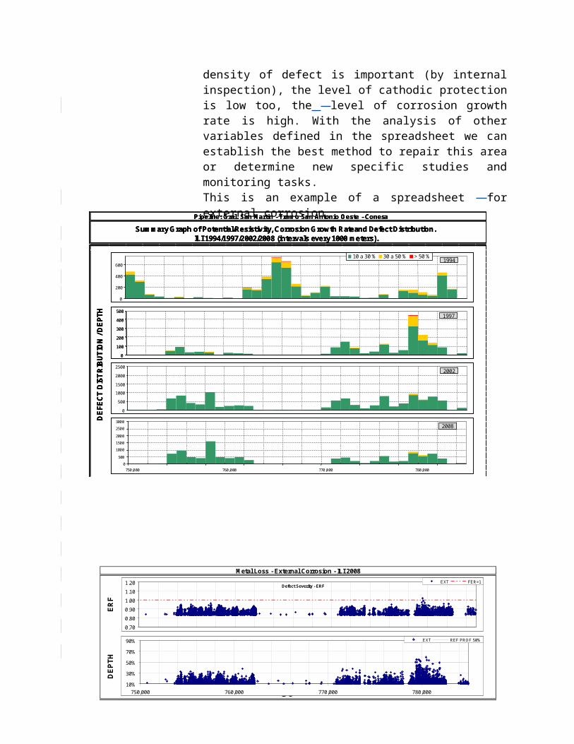
increases the capacity. The advanced flaring system often comes as a self-erecting, trailer mounted design. The self-erecting design solution offers a fast solution for temporary flaring operations.
Note: Appendix XVII provides technical paper on Mobile Flaring.
5.2.2.3 Choosing a method for emptying gas systems
Transmission system operators often need to empty gas systems due to planned or unplanned maintenance or construction work. The operator has to choose between different methods for this work. He has to perform his work environmentally friendly, safe, often under time pressure, to an acceptable cost and of cause according to national regulation. The methods he can use are venting, flaring and transferring by compressors or combinations of these methods.
In Aappendix XVIII a decision making process for choosing between different methods has been illustrated. The decision making process is based on a tree analysis where the decision maker has to go through a number of steps. These steps include national and international regulation, company policy, technical feasibility, type of operation and ends up with a choice of method. The advantage of using such a process is that the operator gets a transparent and uniform decision process from case to case.
50

4.3[5.3] SummaryIn summary, most companies/respondents pay attention to the whole range of environmental impacts. A particular focus is on greenhouse gas (which is ranked highest) and air pollution species. The emission of greenhouse gas caused by gas transmission system is mainly resulting from venting and from leakage of installations such as meters, and valves. Several companies use new technologies like CHARM or GasCAM for detection of emission source/s and thus reduction of the footprint. Also emptying of pipelines by venting or flaring is an issue of concern for TSOs. Best practice (i.e. environmentally and economically optimized) procedures are given for both emptying methods.
The emission of air pollution mainly comes from combustion machines such as compressors and boilers. The practices/methodologies to reduce the footprint by most companies are concentrated on optimization of machines and operations.
51

5.0[6.0] Conclusion and RecommendationMost IGU WOC 3 members are pipeline operators. The mean age of their respective pipeline network is between 15 and more than 25 years. This also means that a lot of valuable experiences have been collected by the operators in terms of managing pipeline integrity.
Based on the surveyed responses, WOC 3 agrees that pipeline integrity management should start from the design phase i.e. sound design in accordance to recognised and proven industry standards. Pipeline integrity management should further ensure that a pipeline (system) is constructed, tested and commissioned in accordance with recognised and proven good practices as well as industry standards. During operation phase, the pipeline system should be operated and maintained inclusive of its integrity management, following best practices and utilising technologies and tools that are effective and efficient in delivering the business, operations and safety targets.
Managing pipeline integrity mainly is about managing risk of failure i.e. leak and/or rupture and ensuring avoidance of leak and/or rupture by having appropriate control and applying mitigation measures so that the risk is controlled within the As Low as Reasonably Practicable (ALARP) region. In managing pipeline integrity, appropriate identification of threats is among the important activities as not all threats may be applicable to a specific pipeline section. Based on the surveyed responses, WOC 3 members use their own experience with operation, inspection and maintenance (including repair and failure history) as well as risk assessment and combination of own data and data from industry incident data bases (EGIG, DOT etc.) in order to identify the threats which have a significant impact on the integrity of their pipelines. Each threat for pipeline integrity mentioned in the survey questionnaires (i.e. third party intrusion/external interference, external corrosion, human/operator error, geotechnical problems, material defects and construction error) has its own mitigation measures. For each threat there are at least three mitigation measures existing, which could serve as a best practice or reference. Most companies/respondents already apply the existing mitigation measures as applicable to their pipelines.
Another important aspect in managing pipeline integrity is the effectiveness of threats mitigation measures. Ultimately, the effectiveness is measured from different perspectives: (i) safety objectives i.e. minimized number of leaks or ruptures, (ii) business objectives i.e. reliably delivering the gas to customers meeting the contractual requirements, and (iii) environmental impact. According to the survey responses, TSOs use lagging and leading key performance indicators (KPIs) to measure the effectiveness from the various perspectives.
Pipeline integrity management could not be implemented effectively by TSO without the existence of strong and justified regulations established for the sole purpose of sustaining of the technical integrity of a pipeline system as well as protecting the safety of TSO’s employees and the public; as well as to the environment. In formulating the regulations, necessary stakeholders i.e. the government authorities, the public, the TSO and the media need to play its own individual role looking into all angles based on their own expertise,
52

knowledge and experiences so that the regulations can be of a ‘win-win’ situation taking into considerations of safety and economic progress of the host country.
In conclusion, WOC 3 managed to investigate and identify the most important threats to a gas transmission pipeline and obtained substantial information on and insight into mitigation measures for each threat. In the present report WOC 3 also lists ways to measure the effectiveness of the Integrity Management System in general and of the mitigation measures in particular by utilising appropriate lagging and leading KPIs.
This report also summarizes a number of best practices, new technologies and lessons learnt in the overall pipeline integrity management as well as environmental footprint reductions of gas transmission system. The details of the above are given in the Appendix section. It is intended and welcome that other TSOs or gas transmission companies adopt the best practices, new technologies and lessons learnt in accordance to their organisation’s requirement and as they see fit.
53