· Web viewSpring loaded linkage from the nose gear to the adjustable rudder pedals allow for nose...
28
Baron 95-A55, 1963, SN TC-483, POH Information Wingspan: 37’ 10” Height: 9’7” Length: 26’8” Engine: IO-470-L, Fuel Injected, air cooled, six cylinder, horizontally opposed engines, 260hp at 2625rpm, TBO 1500hrs. Zero Thrust : MP 12”, Propeller lever - Retard to Feather Detent Max Cyl Head 460deg F Normal 200-460deg F Max Oil Temp 225deg F Min Takeoff Temp: 75deg F Max Oil Press 80PSI Min Oil Press: 30PSI Normal 30-60PSI Fuel Press Max: 17.5PSI Min: 1.5PSI Normal: 5 – 17.5 PSI MP Max: 29.6in HG Normal: 15-29.6in HG Tach Max: 2625 Normal: 2000-2625 Vacuum: Two Vacuum pumps, one on each engine. A check valve operates in case of a single pump failure. Min: 3.75 Yellow 3.75-4.8 Green: 4.8-5.25 Red: 5.25in HG Prop: 2 bladed constant speed, full feathering 78” McCauley, Alcohol DeIce. Springs aided by counter – weights move the blades to high pitch (low rpm). Engine oil under governor-boosted pressure moves the blades to low pitch (high rpm)
Transcript of · Web viewSpring loaded linkage from the nose gear to the adjustable rudder pedals allow for nose...
Baron 95-A55, 1963, SN TC-483, POH Information
Wingspan: 37’ 10” Height: 9’7” Length: 26’8”
Engine: IO-470-L, Fuel Injected, air cooled, six cylinder, horizontally opposed engines, 260hp at 2625rpm, TBO 1500hrs.
Zero Thrust: MP 12”, Propeller lever - Retard to Feather Detent
Max Cyl Head 460deg F Normal 200-460deg F
Max Oil Temp 225deg F Min Takeoff Temp: 75deg F
Max Oil Press 80PSI Min Oil Press: 30PSI Normal 30-60PSI
Fuel Press Max: 17.5PSI Min: 1.5PSI Normal: 5 – 17.5 PSI
MP Max: 29.6in HG Normal: 15-29.6in HG
Tach Max: 2625 Normal: 2000-2625
Vacuum: Two Vacuum pumps, one on each engine. A check valve operates in case of a single pump failure.
Min: 3.75 Yellow 3.75-4.8 Green: 4.8-5.25 Red: 5.25in HG
Prop: 2 bladed constant speed, full feathering 78” McCauley, Alcohol DeIce. Springs aided by counter –weights move the blades to high pitch (low rpm). Engine oil under governor-boosted pressure moves the blades to low pitch (high rpm)
Alcohol Ammeter: 7-12 Amps
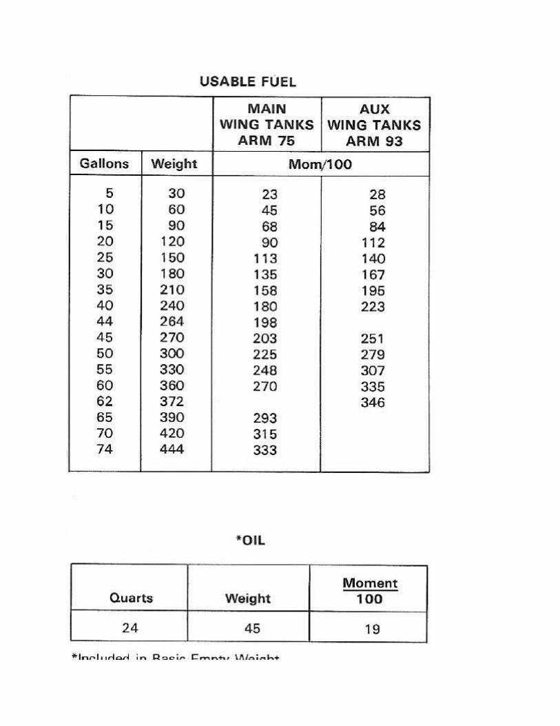
Fuel: 100LL preferred, 100 min, 136gal useable, 142gal total.
Yellow arc: E-1/4 Full, Take off and Landing on Main Fuel Tank Only. A red auxiliary fuel tank annunciator light will illuminate if either one of the aux fuel tanks is selected when the landing gear is extended.
Maximum Slip or Skid Duration: 20 seconds.
Fuel Sumps: 8 total.

Oil: 12 qts max, Currently using Phillips 20W50 in the winter, 100W Aeroshell in the summer
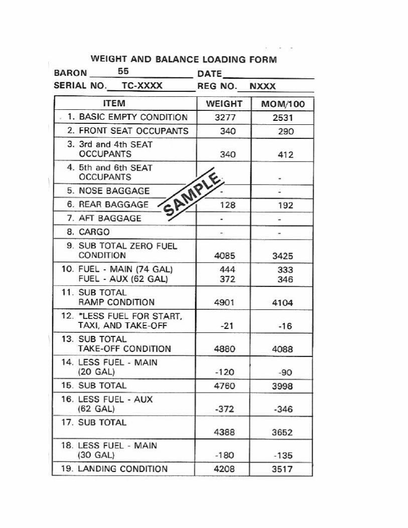
Max Ramp wt: 4901, Max Take-Off and Landing Wt: 4880
Baggage: 400lbs Aft, 270lbs forward
Normal Category: No acrobatic maneuvers, including spins prohibited.
Wing Loading: 4.4G to -3.0G with Flaps up
Maximum people: 5 passengers, 1 pilot.
MEL: Kinds of operation per POH.
Landing Gear: Max gear extended 150MPH
Flight into Known Icing: Not Allowed.
Propeller is Anti-Ice System: Turn On before entering icing conditions. Tank is located in floor of forward baggage area. Capacity is 3US Gals. With a full tank, system endurance is approximately 120 minutes.
Deice Boots: Be careful not to drag fuel hoses over boots during fueling. Do not operate the system unless engine is running.
Oxygen: See pg 4-17, 18
Emergency Static Air: Located lower sidewall adjacent to pilot. Turn to ON to use the alternate static vent. Provides static pressure from inside the cockpit should the outside static port become blocked.
Vmc must be done at least 5000 feet above ground in clear air only.
Max Demonstrated Crosswind: 22kts
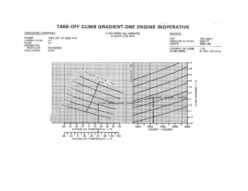
Single Engine Service Ceiling: See pg 5-32
W&B: Insert Graphs and Loading Form here
Parking Brake: Located just left of the elevator tab wheel on the pilot’s subpanel. To set parking brakes, pull control out and depress the pilot’s toe pedals until firm. Push the control in to release brakes.
Brake reservoir: Located thru the nose baggage compartment.

Battery: Located in the floor of the forward baggage area. Two 12V batteries in series giving 24V battery system
Generators: Two 40Amp, 24Volt Generators. Generators don’t charge unless RPM is greater than 1500.
External Power: Located in the outboard side of the left engine. Battery switch should be ON.
Tires: 6.5X8ply mains, 5.00x5ply nose wheel inflated to 50psi.
Control Surfaces: Bearing supported and operated thru push-pull rods and cable systems terminating in bell cranks.
Nose wheel: Spring loaded linkage from the nose gear to the adjustable rudder pedals allow for nose wheel steering.
Trim: Elevator, aileron, rudder.
Flaps: Three Position Switch (Up, Down, OFF). Limit switches automatically turn off the electric motor when the flaps reach the extremes of travel.
Flap lights: Green for UP, Red for DOWN. Intermediate 20 and 10 deg position are indicated by lines painted on the leading edge of the left flap.
Landing Gear: Adjustable linkage connected to an actuator assembly mounted beneath the front seats. The actuator (worm gear) is driven by an electric motor.
Two position switch: Up and Down.
Position Indicators: Red for gear up, Green for gear down. A mechanical pointer at the base of the console shows the position of the nose gear.
Squat Switch: Main strut safety switch operates the control circuit when the strut is compressed.
Warning horn: Throttle below about 12”MP with gear up.
Manual Extension: Can extend but not retract. Approximately 55 turns of the crank.
Cowl Flaps: Amber light indicates either cowl flap is open.
Internal lights: Three rheostats located beneath the control console.

Heater: Located in the nose. Five outlets: forward of the pilot and copilot seats, aft of the copilot seat, aft of the copilot side middle passenger seat, and defrost. A fuse is located. When heating, Cabin Air control should be full forward. If the Cabin Air control is pulled out more than halfway, the heater will not operate. The blower will only work if the landing gear is extended and the Cabin Air Control is pushed in at least halfway.
Stall Warning Horn: Triggered by a sensing vane on the left wing. The pitot heat switch applies electricity to heat the stall warning vane.