· Web viewSimply supported One end continuous Both ends continuous Cantilever Members not...
18
FACULTY OF ENGINEERING DEPT. OF CIVIL ENGINEERING REINFORCED CONCRETE (2) SECOND SEMESTER 2015-2016 SERVICEABILITY LECTURER Dr. SA'AD A. AL-TA'AN ~ 1 ~ PHILADELPHIA UNIVERSITY
Transcript of · Web viewSimply supported One end continuous Both ends continuous Cantilever Members not...

FACULTY OF ENGINEERING
DEPT. OF CIVIL ENGINEERING
REINFORCED CONCRETE (2)
SECOND SEMESTER 2015-2016
SERVICEABILITY
LECTURER Dr. SA'AD A. AL-TA'AN
~1~
PHILADELPHIA UNIVERSITY

SERVICEABILTY
Serviceability limit states refer to the performance of structures under normal service loads and are concerned with the uses and / or occupancy of structures. Serviceability is measured by considering items that may disrupt the use of structures but do not usually involve collapse:
1- The magnitude of deflections;2- The cracks width;3- Vibrations of structures;4- The amount of surface deterioration of the concrete, and5- Corrosion of the reinforcement.
DEFLECTION
Excessive deflection can cause the followings:1- Cracking or crushing of nonstructural components, such as partitions.2- Lack of fit of windows and doors.3- Walls out of plumb.4- Ponding on flat surfaces.
In reinforce concrete members, the total deflection at any time is the sum of the short-time and long-time deflection. Short -time (Short -term or sometimes called instantaneous) deflection is that which occur instantaneously upon the application of the load. Long-time (long- term) deflection represents the increase in the short time deflection due to creep and shrinkage of concrete.
Factors Affecting Short Time Deflection:1- Magnitude and distribution of loading,2- Span and support conditions,3- Materials and section properties, and4- Amount and extent of cracking.
Factors Affecting Long Time Deflection:1- The previous four factors,2- Creep and shrinkage of concrete, and3- Amount of compression steel.
ACI-Code Recommendation for Controlling Deflection:The ACI-Code recommends the following span / depth ratios for beams and one-way slabs, unless deflection is computed.
~2~
S. A. AL-TA’AN
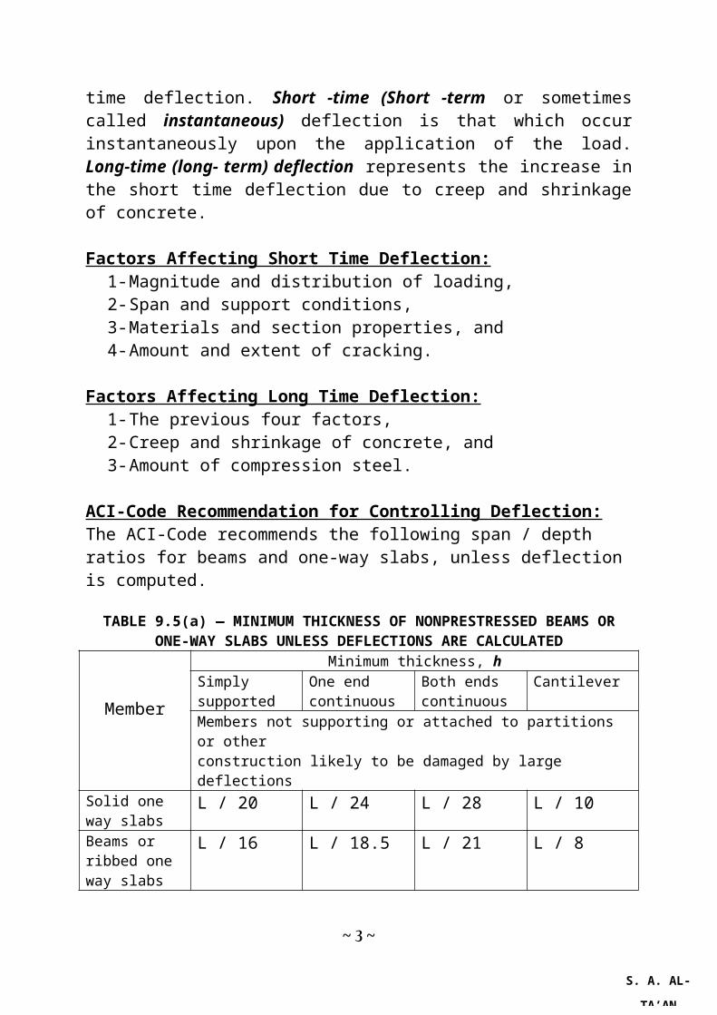
TABLE 9.5(a) — MINIMUM THICKNESS OF NONPRESTRESSED BEAMS OR ONE-WAY SLABS UNLESS DEFLECTIONS ARE CALCULATED
Member
Minimum thickness, hSimply supported
One end continuous
Both ends continuous
Cantilever
Members not supporting or attached to partitions or otherconstruction likely to be damaged by large deflections
Solid one way slabs
L / 20 L / 24 L / 28 L / 10
Beams or ribbed one way slabs
L / 16 L / 18.5 L / 21 L / 8
Notes : Values given shall be used directly for members with:
i. Normal weight concrete, andii. Grade 400 reinforcement.
For other conditions, the values shall be modified as follows:
(a) For lightweight concrete having density, wc , in the range of 1400 to 1800 kN/ m3, the values shall be multiplied by (1.65 – 0.0003wc) but not less than 1.09.(b) For fy other than 400MPa, the values shall be multiplied by (0.4 + fy/667).(c) L = span length = clear span for cantilever beam, = clear span + depth of member ≤ c / c of supports for members not built integrally with the supports, = dist. c / c of supports for continuous members.(d) The above limitations are applicable for members reinforced with steel having 276 MPa ≤ fy ≥ 550 MPa .
Calculation of Short Time Deflection:The instantaneous deflection of any elastic structural member, can be calculated from the following general equation:
Δ=CONS .M max . L2
Ec . I eff (1)Mmax= maximum bending moment within the span, L = span, Ec = Elastic modulus of the material, Ieff = effective second moment of area of the cross-section, and CONS. = factor that depends on the support conditions and the loading pattern. The following values of the deflection may be used instead of the above equation.
~3~
S. A. AL-TA’AN

For cracked reinforced concrete members, the second moment of area varies along the span. At a crack, it equals to the second moment of area of a fully cracked section (Ict), while between the cracks it is more than this value since concrete between cracks carries some tensile stresses and the effective second moment of area is I ct≤Ieff ≤I ut or ( I g).
Mcr / Mm Variation of (Ieff) with the cracking moment
In calculating Ieff. for reinforced concrete beams, the equation proposed by Branson and adopted by the ACI –Code is used. At any section, the effective second moment of area:
I eff =Iut (M cr
M)4+ I ct [1−(
M cr
M)4 ]
(2)Iut = Uncracked transformed second moment of area of the cross-section, without much loss of accuracy this can be assumed equal to Ig = second moment of area of the gross concrete section,I ct = Second moment of area of the cracked transformed section,
~4~

M = bending moment at the section considered, Mcr= cracking moment = fr .Iut / yt
fr = modulus of rupture of concrete = 0 . 62√ f c'
y t = distance from the neutral axis to the tension face,For uniformly loaded simply supported beams, the effective second moment of area along the whole span can be written as follow:
I eff =I ut(M cr
M max .)3+ I cr[ 1−(
M cr
M max .)3 ]
(3a)or
I eff =I g(M cr
Mmax .)3+ I cr[ 1−(
M cr
M max .)3 ]
(3b)Equation (1) can be rewritten in a more detailed form as follow:
Δ= 5k48
M max . L2
Ec . I eff (4)k = factor that depends on the type and arrangement of loading, as shown below:
k=1. 2−0. 2M o
M m for uniformly loaded beams (5)
k=1. 2−0. 4M o
M m for beams with concentrated loads (6)Mo = total statical moment as if the beam is simply supported,Mm = mid span moment.
The following Table shows some of the usual cases for some loaded beams.
Values of k for different types of beams and loadingBeam Type Loading kSimply supported Uniformly loaded 1.0Simply supported Mid span concentrated load 0.8One end continuous Uniformly loaded 0.8Both ends continuous Uniformly loaded 0.6Cantilever Uniformly loaded 2.4Cantilever concentrated load at the free end 3.2
AVERAGE EFFECTIVE (Ia) FOR CONTINUOUS BEAMS
The average effective second moment of area (Ia) along the whole span can be calculated using the following equations:
(1) Beams with one end continuous:
~5~
S. A. AL-TA’ANS. A. AL-TA’AN

I a=0 .85 Im+0 .15 I e (7a)(2) Beams with both ends continuous:
I a=0 .7 Im+0 .15 ( I e1+ Ie 2) (7b)Where
Im = effective second moment of area at mid span,Ie = effective second moment of area at the continuous end,Ie1 = effective second moment of area at the continuous end 1,Ie2 = effective second moment of area at the continuous end 2.
REPEATED LIVE LOAD:
I rep .=ψ ( I e)D+ L+(1−ψ )I g (8a)
ψ=M u−M D+L
M u−M cr (8b)
EXAMPLE 2:Calculate the short-term DL and LL deflection of the beam of example (1). Calculate also the long-term deflection. The beam is subjected to a superimposed dead load 9.0 kN/m and a live load of 12.0 kN/m. The beam is simply supported on a clear span of 5.7 m and 6.0 m (c/c). fc
'=25 MPa and fy=400 MPa.
SOLUTIONEc=4730√25=23650 MPan=200000/23650=8.46≈8UNCRACKED SECTIONAg=300×450=135000 mm2 (concrete gross area)Ig=0.3×0.453/12=0.002278 m4 (moment of inertia of the concrete gross area)Aut = 300×450 +7 ×1256= 143792 mm² (uncracked transformed area, 6.5% more than Ag)
yc=b.h2/2+(n−1) As . d+(n−1 ) A s
' .d'
b. h+(n−1 ) A s+(n−1) A s'
(this is for double reinforced rectangular section).yc = (300×450×225+7×1256×390)/(143792)=235 mm (225 for Ag) Iut = 0.3(0.45)3/12 + 0.3×0.45(0.235-0.225)2 +7×0.001256(0.39-0.235)2 = 0.002503 m4 (moment of inertia of the uncracked transformed section, 9.9 % more than Ig)
~6~
S. A. AL-TA’AN

Cracking Momentf
r=0 .62√25=3 . 1MPa
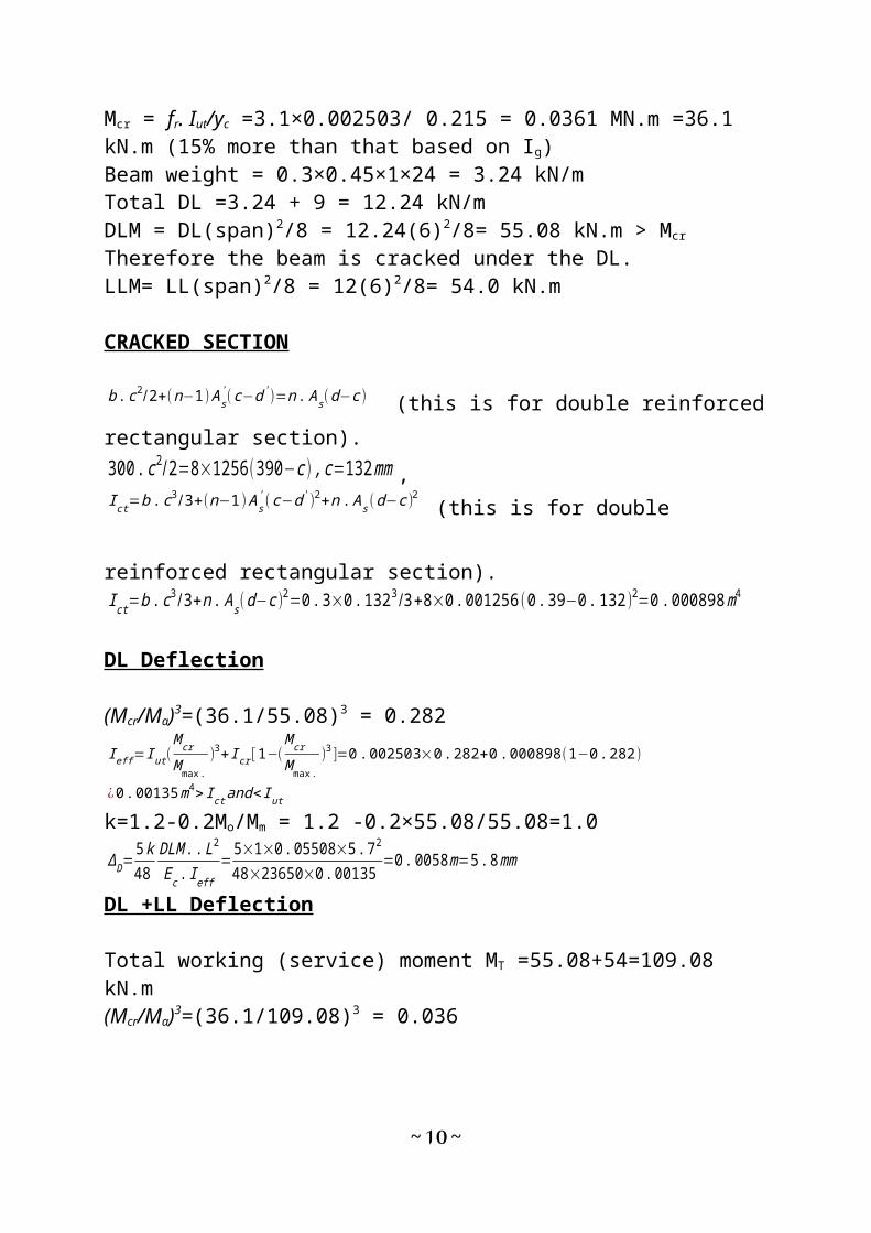
Mcr = fr. Ig/yc =3.1×0.002278/ 0.225 = 0.0314 MN.m =31.4 kN.mMcr = fr. Iut/yc =3.1×0.002503/ 0.215 = 0.0361 MN.m =36.1 kN.m (15% more than that based on Ig)Beam weight = 0.3×0.45×1×24 = 3.24 kN/m Total DL =3.24 + 9 = 12.24 kN/m DLM = DL(span)2/8 = 12.24(6)2/8= 55.08 kN.m > Mcr
Therefore the beam is cracked under the DL.LLM= LL(span)2/8 = 12(6)2/8= 54.0 kN.m
CRACKED SECTION
b . c2/2+(n−1 ) A s' (c−d ' )=n. A s(d−c )
(this is for double reinforced rectangular section).300 . c2 /2=8×1256(390−c ) , c=132 mm ,I ct=b . c3 /3+( n−1) A s
' (c−d ' )2+n . As (d−c )2
(this is for double reinforced rectangular
section).I ct=b .c3 /3+n . A s (d−c )2=0 .3×0.1323 /3+8×0 . 001256(0 .39−0. 132)2=0 .000898 m4
DL Deflection
(Mcr/Ma)3=(36.1/55.08)3 = 0.282
I eff =I ut (M cr
M max .)3+ I cr [ 1−(
M cr
M max .)3 ]=0. 002503×0 .282+0 . 000898(1−0 . 282)
¿0 . 00135 m4> I ct and< I ut
k=1.2-0.2Mo/Mm = 1.2 -0.2×55.08/55.08=1.0
ΔD=5 k48
DLM . .L2
Ec . I eff=5×1×0 .05508×5. 72
48×23650×0. 00135=0 .0058 m=5 .8 mm
DL +LL Deflection
Total working (service) moment MT =55.08+54=109.08 kN.m(Mcr/Ma)3=(36.1/109.08)3 = 0.036
I eff =I ut (M cr
Mmax .)3+ I cr[ 1−(
M cr
Mmax .)3 ]=0. 002503×0 .036+0 .000898(1−0 .036 )=0.000956 m4
> Ict and < Iut
k=1.2-0.2Mo/Mm = 1.2 -0.2×109.08/109.08 =1.0
~7~
S. A. AL-TA’AN

ΔD+L=5 k48
M T . L2
Ec . I eff= 5×1×0 .10908×5.72
48×23650×0. 000956=0 . 0163 m=16 .3 mm
LL Deflection
ΔL=ΔD+L−ΔD=16.3−5. 8=10 .5 mm
LONG-TERM DEFLECTIONACI-Code Recommendation for Estimating Long Time Deflection:
Long term deflection due to creep and shrinkage of flexural members (normal weight and lightweight concrete) shall be determined by multiplying the immediate deflection caused by the sustained load considered, by the following factor:
ΔT=ξ . Δ D
1+50 ρ', ρ' = A'
s /(b.d) = 0/b.d =0, ΔT=
ξ . ΔD
1+50 ρ' =ξΔD
1+50( 0)=ξΔD
The time dependent factor (ξ) for sustained loads is as shown in Table (3) below:
Period 0 3 months 6 months 9 months 5 yearsFactor (ξ ) 0 1.0 1.2 1.4 2.0∆T 0 5.8 1.2×5.8=6.96 1.4×5.8=8.12 2.0×5.8=11.6∆T+∆D 5.8 11.6 12.76 13.92 17.4∆T+∆D+∆L 16.3 22.1 23.26 24.42 27.9
0 10 20 30 40 50 60 700
5
10
15
20
25
30
long-term deflection total deflection
Time in Months
Defle
ction
mm
~8~

LOAD INDUCED CONCRETE CRACKING
1- Flexural cracks (caused by flexural tensile stresses and usually perpendicular to the longitudinal axis of the members) occurs when the tensile stress exceeds the tensile strength of concrete.
2- Shear cracks [caused by diagonal tensile stresses (flexural + shear stresses) and usually inclined with the longitudinal axis of the members) occurs when the diagonal tensile stress exceeds the tensile strength of concrete.
3- Flexure – shear cracks (caused initially by flexural stresses and propagated by the diagonal tensile stresses). It starts perpendicular to the axis of the member and then inclined toward the point of zero shear.
4- Web – shear cracks (occurs in thin webs at zones of high shear stresses).5- Spiral cracks (caused by torsional stresses).6- Longitudinal splitting cracks (occurs parallel and below or at the level of
the longitudinal bars and caused by radial interfacial bond stresses).
~9~
S. A. AL-TA’AN
Types of Cracks in Reinforced Concrete Members
CONTROL OF FLEXURAL CRACKING
Cracking of concrete (plain or reinforced) occurs when the tensile stress (strain) exceeds the tensile strength (cracking strain) of concrete.Tensile strength of concrete is measured by three tests:
1- Direct tensile strength, f t'=0 . 33√ f c
'
2- Splitting tensile strength, f sp=0 . 58√ f c'
3- Flexural strength (Modulus of rupture), f r=0 . 62√ f c'.
The cracking strain of concrete (80-150 μs) is only a small fraction of the steel strain which it is surrounds. Excessive cracking can cause the followings:
1- Wide cracks impair the appearance of the structure.2- Wide cracks may allow corrosive elements (humidity) to penetrate to the
main reinforcement.
FACTROS AFFECTING CRACKS SPACING AND WIDTH:
1- Cracks width proportional to the steel stress.2- Cracks spacing proportional to the distance from the reinforcing bar.3- Cracks width and spacing are strongly influenced by concrete cover.4- Cracks width is independent on the reinforcement ratio, concrete strength,
bar size and curing regime.5- Plain bars have less crack control characteristics than deformed bars.
Width is ≈ 13% more.PREDICTION FORMULA:
Gergely and Lutz formula:wmax .=13 .3×10−6 R . f s
3√dc . A (9)Frosch formula:
wmax .=2 .f s
EsR√dc
2+( S /2 )2
(10) R=(h−c )/( d−c )fs= steel stress in MPa,dc = dist. from the tension face to the center of the lowest reinforcing layer,A = 2(h-d).b / (no. of bars), andS = bars spacing c/c.
~10~
S. A. AL-TA’ANS. A. AL-TA’AN

ACI-CODE RECOMMENDATION FOR BARS SPACINGThe spacing shall not exceed:S=380(276
f s)−2 .5C c≤305 (276/ f s )
Cc = clear cover
Permissible Crack WidthsMembers subjected toPermissible crack widths (mm)
Dry air0.4Moist air, soil0.3De-icing chemicals0.18Seawater and seawater spray0.15Use in water retaining structures0.1
~11~
Bars Spacing c / c (mm)fs=170 MPa
fs=140 MPa
Clear Cover (mm) Cc300250200150100500
600
500
400
300
200
100
0
fs=170MP
fs=140MP
Relationship between clear cover and bars spacing
S. A. AL-TA’AN

EXAMPLE 3
Estimate the maximum probable crack width for the beam of example 2, at the centroid of steel and at the tension face using the two equations and ACI recommendations.
SOLUTION
Mcr = 36.1 kN.mMw = 109.08 kN.m > Mcr
Therefore the section is cracked under the DL+LL.Ict = 0.000898 m4
Gergely and Lutz formula
f s=n M (d−c )Ict
=8 0 .10908(0 . 39−0. 132)0 .000898
=250 . 7 MPa
At the tension faceR=450−132
390−132=1 .23
dc = 40 + 10 + 20 / 2 = 60 mmA = 2.b(h-d) / No. of bars=2×300(450-390)/4=9000 mm2 / barwmax .=13 .3×10−6 R . f s
3√dc . A
¿13 .3×10−6×1 .23×250 .7 3√60×9000=0 .33mm
At the centroid of the steel level
R=390−132390−132
=1. 0
wmax .=13 .3×10−6 R . f s3√dc . A
¿13 .3×10−6×1 . 0×250 . 7 3√60×9000=0 .27 mm
Frosch formula,
Spacing of bars = (300-2×70) / 3 = 53.3 mmAt the tension face
wmax .=2 .f s
EsR√dc
2+( S /2 )2=
2 250.7200000
1. 23√(60)2+(53 .3 /2)2=0 .20 mm
At the centroid of the steel levelR=(390−132 )/(390−132)=1 . 0
~12~
S. A. AL-TA’AN

wmax .=2 .f s
EsR√dc
2+( S /2 )2=2250 .7200000
1 .0 √(60 )2+(53.3 /2 )2=0.16 mm
ACI-CODE RECOMMENDATION FOR BARS SPACING
Actual spacing = (300-2×70)/3=53.3 mmThe spacing shall not exceed:S=380276
f s−2 .5 C c≤305(276/ f s )
(11)Cc = clear cover = 40 + stir. Dia. (10) =50 mmS=380276
250 . 7−2. 5×50=293 mm≤305(276/250 .7 )=336 mm
Max. S = 293 mm > actual S = 53.3 mm (O.K.)VIBRATIONS
Reinforced concrete buildings are not, as a rule, subject to vibration problems. This robustness is due to their mass and stiffness. Occasionally, long-span floors or assembly structures will be susceptible to vibrations induced by persons walking, dancing, or exercising. These activities induce vibrations of approximately 2 to 4 cycles per second (hertz).If a floor system or supporting structure has a natural frequency of less than 5 cycles per second, its vibrational properties should be examined more closely to ensure that floor vibrations will not be a problem. Fortunately, it is relatively easy to estimate the natural frequency, f, of a floor if its deflection can be calculated:f =0 . 18√g / Δi (D+L)
g = acceleration due to gravity = 9.81 m/sec2, and ∆i(D+L) = short-term deflection due to Dead and Live loads.
~13~
S. A. AL-TA’AN