ViewPort v4 June 2009 - Mouser Electronics IV Integrating your Program with ... •interfacing with...
66
ViewPort v4 June 2009 Copyright © 2009 by myDancebot.com
Transcript of ViewPort v4 June 2009 - Mouser Electronics IV Integrating your Program with ... •interfacing with...

ViewPort v4June 2009
Copyright © 2009 by myDancebot.com

ViewPort Manual
by Hanno Sander
Table of Contents
ForeWord .............................................................................................2
3
............................................................................................................6Part I Welcome
............................................................................................................8Part II Introduction
............................................................................................................... 9Overview 2.1
...............................................................................................................10Parallax Propeller 2.2
...............................................................................................................11Uses 2.3
...............................................................................................................12About myDanceBot 2.4
............................................................................................................13Part III Getting Started
...............................................................................................................14Installation 3.1
...............................................................................................................15Load a Tutorial 3.2
...............................................................................................................16Views 3.3
...............................................................................................................17Advanced Views 3.4
...............................................................................................................18View IO Port Status 3.5
...............................................................................................................19View and Change Variables 3.6
...............................................................................................................20Connect/Disconnect 3.7
............................................................................................................21Part IV Integrating your Program with ViewPort
...............................................................................................................22Overview 4.1
...............................................................................................................23Integrate ViewPort into spin code 4.2
...............................................................................................................24Configure ViewPort Settings 4.3
...............................................................................................................25Source Code for Tutorial 1 4.4
............................................................................................................26Part V Reference (Windows Application)
...............................................................................................................27Menus 5.1
...............................................................................................................28Menus Part 2 5.2
...............................................................................................................29Folder Structure 5.3
...............................................................................................................30Tutorials 5.4
...............................................................................................................31Connection Properties 5.5
4
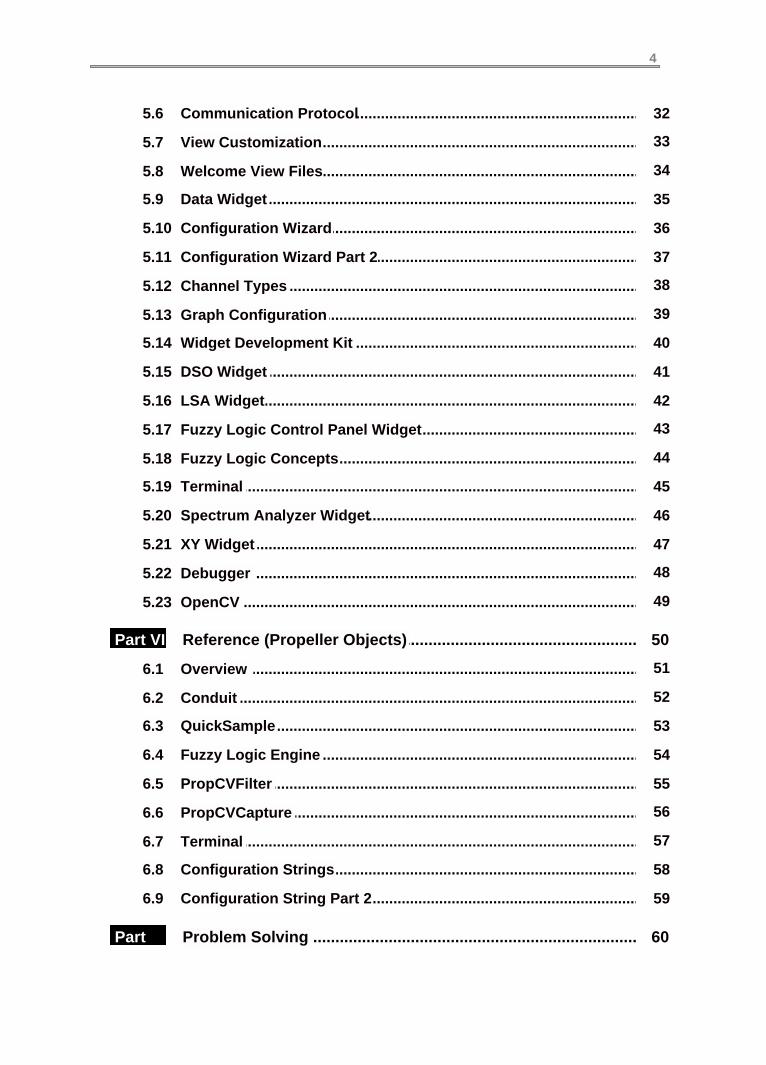
...............................................................................................................32Communication Protocol 5.6
...............................................................................................................33View Customization 5.7
...............................................................................................................34Welcome View Files 5.8
...............................................................................................................35Data Widget 5.9
...............................................................................................................36Configuration Wizard 5.10
...............................................................................................................37Configuration Wizard Part 2 5.11
...............................................................................................................38Channel Types 5.12
...............................................................................................................39Graph Configuration 5.13
...............................................................................................................40Widget Development Kit 5.14
...............................................................................................................41DSO Widget 5.15
...............................................................................................................42LSA Widget 5.16
...............................................................................................................43Fuzzy Logic Control Panel Widget 5.17
...............................................................................................................44Fuzzy Logic Concepts 5.18
...............................................................................................................45Terminal 5.19
...............................................................................................................46Spectrum Analyzer Widget 5.20
...............................................................................................................47XY Widget 5.21
...............................................................................................................48Debugger 5.22
...............................................................................................................49OpenCV 5.23
............................................................................................................50Part VI Reference (Propeller Objects)
...............................................................................................................51Overview 6.1
...............................................................................................................52Conduit 6.2
...............................................................................................................53QuickSample 6.3
...............................................................................................................54Fuzzy Logic Engine 6.4
...............................................................................................................55PropCVFilter 6.5
...............................................................................................................56PropCVCapture 6.6
...............................................................................................................57Terminal 6.7
...............................................................................................................58Configuration Strings 6.8
...............................................................................................................59Configuration String Part 2 6.9
............................................................................................................60Part VII
Problem Solving

5
............................................................................................................62Part VIII
Glossary
............................................................................................................64Part IX How To Buy

Part IWelcome
ViewPort

1.1 WelcomeViewPort Development Studio: Build Advanced Projects"Welcome to ViewPort, the best tool for building advanced projects with the ParallaxPropeller.
What is ViewPortThe ViewPortTM Development Studio combines a graphical application with software for theParallax PropellerTM microcontroller to help you build advanced projects more quickly. Variablesused in a Propeller program are shared over a high speed serial connection with ViewPort toallow you to control and monitor the program as it runs. This is known as SCADA (SupervisoryControl And Data Acquisition). Data can be graphed, measured, or logged. Various controlsallow you to change variables in your program as it's running. ViewPort can be integrated intoany spin program - it requires one cog and a single line of code at the start of your program. It'seasy to get started with plenty of tutorials, videos and documentation. It is also configurable andextensible so you can customize it to your needs.
How can ViewPort help medebug spin code with debugger and by viewing variable values over time·pc-based controller- control an embedded system from your desktop·tuning and calibrating constants, for example tuning a PID controller·interfacing with other hardware by viewing timing in logic analyzer mode·take measurements with the DSO, LSA, Spectrum Analyzer, Data Logger...·SCADA prototype tool to integrate PC with real time data acquisition and control·teaching tool for interfacing with hardware like sensors, motors...·robot design platform to monitor internal robot state as you control it·fuzzy logic engine and graphical editor·video capture and vision processing with OpenCV·
Features:High Speed connection to Propeller Memory·Change and Monitor variables in your program as it runs·Analyze data with Oscilloscope, Logic State Analyzer, Spectrum Analyzer modes·View the state of the Input/Output port at up to 80MHz·Create Custom Visualizations. Build your own controls with the Development Kit·Integrate Fuzzy Logic into your program, with Graphical Tuning·Capture Video, apply Vision Filters, View Video and Apply OpenCV filters·Comprehensive Help Manual, Easy Install/Uninstall·Comprehensive Terminal object support existing print style debugging.·Get started Integrating with ViewPort with Documented, Full Source Tutorials·Plugins include: Integrated Spin Code Debugger, OpenCV Engine·
Installation and Integration:ViewPort is easy to install and the tutorials help you to get started quickly. Integrating ViewPortinto your own programs takes one line of code at the start of your program.
Links:Home Page: http://mydancebot.comBlog: http://blog.mydancebot.comForums: http://forums.mydancebot.comParallax Propeller: http://parallax.com/propellerParallax PE Lab Kit for ViewPort: http://www.parallax.com/Portals/0/Downloads/docs/prod/prop/PE-Lab-ViewPortApps.zip
Copyright © 2007-2009 myDanceBotPropeller is a trademark of Parallax IncViewPort is a trademark of myDanceBotAll Rights ReservedManual Version 2.1, Supports ViewPort Version 4.16
Copyright © 2009 by myDancebot.com
Part I: Welcome7

Part IIIntroduction
ViewPort

2.1 OverviewBackgroundThe Parallax Propeller is a powerful microprocessor used in embedded systems, robotics andadvanced electronic projects. ViewPort uses one of the Propeller microcontroller eightprocessors (cogs) to share data with a graphical application that runs on a PC. This allows usersto monitor and control the program running on the Propeller.
ViewPort Architecture
Architecture WalkthroughThe user's Program runs on the Propeller and has configured some data for sharing withViewPort. The Program may also register other objects, like the QuickSample object to takequick readings of the IO port.
The Conduit object runs in a separate cog from the user's but has access to the shared variableswhich are stored in Propeller main memory. It sends the shared data to the Windows host overthe serial connection. The conduit can also receive commands from the host to change variablesor control ViewPort objects.
Data received by the host is stored in a queue. When the queue is full the oldest measurement isthrown out.
The ViewPort application includes multiple views to display data. Use these views to measureand analyze the data using standard instruments. Data can be logged to different file formats,uploaded to an ftp server, or passed to an external program. Views are defined by XML fileswhich define the layout and base configuration for ViewPort controls. Additional controls can beprogrammed using the Developer's Kit.
Configuration information such as what variables to graph, time scale and bit labels can bemanipulated with the configuration wizard, saved and loaded from configuration files, set usingcontrols presented by the virtual instruments, or included in the user's program
Copyright © 2009 by myDancebot.com
Part II: Introduction9

2.2 Parallax PropellerParallax Propeller: 32 Bit, 80MHz, 8 cog MicroprocessorThe Propeller chip makes it easy to rapidly develop embedded applications. Its 8 processors(cogs) can operate simultaneously, either independently or cooperatively, sharing commonresources through a central hub. The developer has full control over how and when each cog isemployed; there is no compiler-driven or operating system-driven splitting of tasks amongmultiple cogs. A shared system clock keeps each cog on the same time reference, allowing fortrue deterministic timing and synchronization. Two programming languages are available: theeasy-to-learn high-level Spin, and Propeller Assembly which can execute at up to 160 MIPS (20MIPS per cog).
Propeller Specification:Processors: 8 32 bit processors running at up to 80MHzShared Global Resources: 32KB RAM, 32KB ROM, 32 IO PinsDedicated Resources Per Processor: 2KB RAM, 2 General Counters, Video OutputPower: 3.3volt DC, each pin can sink up to 40mA
Propeller Development Environment:The Propeller Tool is a free Editor/Compiler/Loader. Compiled programs are loaded to thePropeller over a serial connection.A large community of users frequent the Parallax Forums: http://forums.parallax.comThe repository of source code object is known as the Object Exchange: http://obex.parallax.comInformation about the Parallax Propeller can be found here: http://www.parallax.com/propeller
Propeller Block Diagram
Courtesy of Parallax Inc.
Copyright © 2009 by myDancebot.com
ViewPort 10
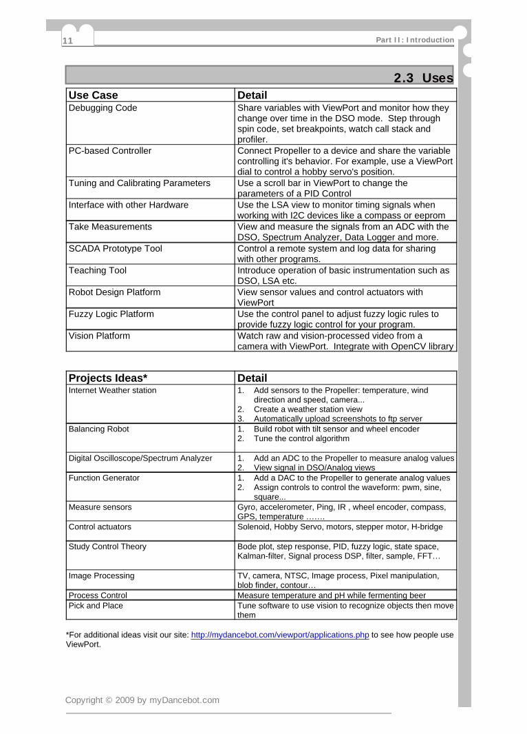
2.3 UsesUse Case DetailDebugging Code Share variables with ViewPort and monitor how they
change over time in the DSO mode. Step throughspin code, set breakpoints, watch call stack andprofiler.
PC-based Controller Connect Propeller to a device and share the variablecontrolling it's behavior. For example, use a ViewPortdial to control a hobby servo's position.
Tuning and Calibrating Parameters Use a scroll bar in ViewPort to change theparameters of a PID Control
Interface with other Hardware Use the LSA view to monitor timing signals whenworking with I2C devices like a compass or eeprom
Take Measurements View and measure the signals from an ADC with theDSO, Spectrum Analyzer, Data Logger and more.
SCADA Prototype Tool Control a remote system and log data for sharingwith other programs.
Teaching Tool Introduce operation of basic instrumentation such asDSO, LSA etc.
Robot Design Platform View sensor values and control actuators withViewPort
Fuzzy Logic Platform Use the control panel to adjust fuzzy logic rules toprovide fuzzy logic control for your program.
Vision Platform Watch raw and vision-processed video from acamera with ViewPort. Integrate with OpenCV library
Projects Ideas* DetailInternet Weather station Add sensors to the Propeller: temperature, wind1.
direction and speed, camera...Create a weather station view2.Automatically upload screenshots to ftp server3.
Balancing Robot Build robot with tilt sensor and wheel encoder1.Tune the control algorithm2.
Digital Oscilloscope/Spectrum Analyzer Add an ADC to the Propeller to measure analog values1.View signal in DSO/Analog views2.
Function Generator Add a DAC to the Propeller to generate analog values1.Assign controls to control the waveform: pwm, sine,2.square...
Measure sensors Gyro, accelerometer, Ping, IR , wheel encoder, compass,GPS, temperature .
Control actuators Solenoid, Hobby Servo, motors, stepper motor, H-bridge
Study Control Theory Bode plot, step response, PID, fuzzy logic, state space,Kalman-filter, Signal process DSP, filter, sample, FFT
Image Processing TV, camera, NTSC, Image process, Pixel manipulation,blob finder, contour
Process Control Measure temperature and pH while fermenting beerPick and Place Tune software to use vision to recognize objects then move
them
*For additional ideas visit our site: http://mydancebot.com/viewport/applications.php to see how people useViewPort.
Copyright © 2009 by myDancebot.com
Part II: Introduction11

2.4 About myDanceBotThe people behind myDanceBot.com believe in building sophisticated, yet affordable products bypushing off the shelf components to their limits. We aim to understand the components we usethrough detailed measurements and analysis- then we engineer the optimal solution.
Thus far, we have developed:ViewPort - the best tool to develop advanced projects with the Parallax Propeller·a Conduit object that moves data to/from the PC at 2Mbps through optimized bitbanging·a QuickSample object that samples the IO port every cycle with advanced self-modifying·code running interleaved on 4 cogsa high performance Fuzzy Logic engine with integrated Control Panel·DanceBot, a balancing robot that can dance·IODreamKit, which replaces a lab's worth of instruments with a single board·Software for the PropScope, Parallax's next generation USB Oscilloscope·Spin Code Debugger, a fully integrated graphical debugger for SPIN code·OpenCV Integration, making it easy to integrate OpenCV vision technology with Propeller·projects
Links:Home Page: http://mydancebot.comBlog: http://blog.mydancebot.comForums: http://forums.mydancebot.comParallax Propeller: http://parallax.com/propeller
Copyright © 2009 by myDancebot.com
ViewPort 12

Part IIIGetting Started
ViewPort

3.1 InstallationRequirements:PC host system:
>500MHz CPU with 5MB HDD Space, 500MB RAM, Mouse·Windows 95,98,2k,XP,Vista·USB 2.0 connection (preferred) or serial to Propeller·Parallax Propeller Tool software installed with USB-serial driver installed·
Parallax Propeller targetParallax propeller chip with power supply·5MHz crystal·EEPROM, LEDs, video input are optional·The Parallax ProtoBoard is a low-cost, high-quality solution for Propeller projects·
Users should be familiar with the Propeller Tool and the Spin language. Familiarity with technicalinstruments like digital storage oscilloscope (DSO) and logic state analyzer (LSA) is a bonus butnot required.
Installation:Download ViewPort and follow the installation wizard to install it. If you're upgrading, the installerwill replace old ViewPort files with the updated versions. Before starting ViewPort, make sure aParallax Propeller is connected to your computer- ideally with a USB connection. USB allows forfaster connection up to 2Mbps.
Uninstall:To uninstall, select the uninstall item from the Windows Start menu.Video Tutorials:The video tutorials show ViewPort in action- view them here:http://mydancebot.com/viewport/videos.phpProblems:If you encounter problems, check the Problem Solving guide or contact us:http://mydancebot.com
Copyright © 2009 by myDancebot.com
ViewPort 14
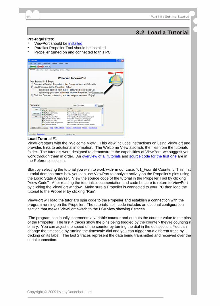
3.2 Load a TutorialPre-requisites:
ViewPort should be installed·Parallax Propeller Tool should be installed·Propeller turned on and connected to this PC·
Load Tutorial #1ViewPort starts with the "Welcome View". This view includes instructions on using ViewPort andprovides links to additional information. The Welcome View also lists the files from the tutorialsfolder. The tutorials were designed to demonstrate the capabilities of ViewPort- we suggest youwork through them in order. An overview of all tutorials and source code for the first one are inthe Reference section.
Start by selecting the tutorial you wish to work with- in our case, "01_Four Bit Counter". This firsttutorial demonstrates how you can use ViewPort to analyze activity on the Propeller's pins usingthe Logic State Analyzer. View the source code of the tutorial in the Propeller Tool by clicking"View Code". After reading the tutorial's documentation and code be sure to return to ViewPortby clicking the ViewPort window. Make sure a Propeller is connected to your PC then load thetutorial to the Propeller by clicking "Run".
ViewPort will load the tutorial's spin code to the Propeller and establish a connection with theprogram running on the Propeller. The tutorials' spin code includes an optional configurationsection that makes ViewPort switch to the LSA view showing 6 traces.
The program continually increments a variable counter and outputs the counter value to the pinsof the Propeller. The first 4 traces show the pins being toggled by the counter- they're counting inbinary. You can adjust the speed of the counter by turning the dial in the edit section. You canchange the timescale by turning the timescale dial and you can trigger on a different trace byclicking on its label. The last 2 traces represent the data being transmitted and received over theserial connection.
Copyright © 2009 by myDancebot.com
Part III: Getting Started15
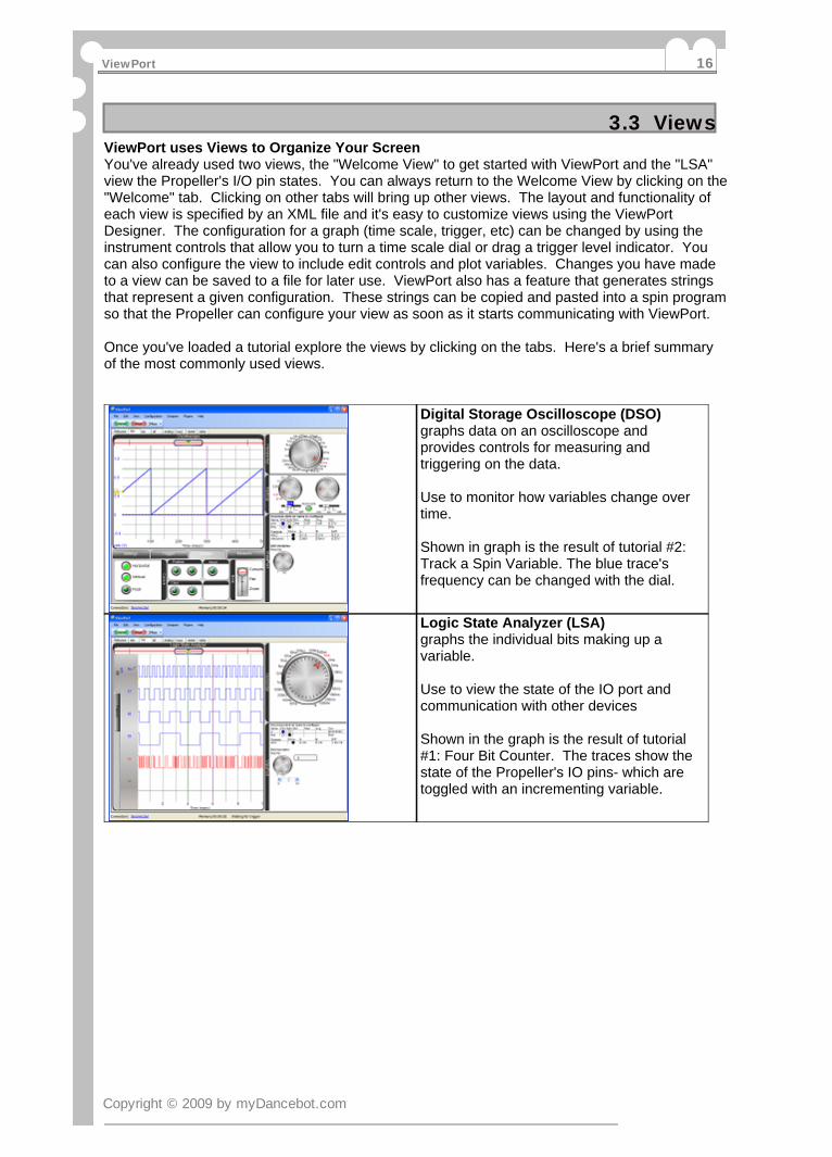
3.3 ViewsViewPort uses Views to Organize Your ScreenYou've already used two views, the "Welcome View" to get started with ViewPort and the "LSA"view the Propeller's I/O pin states. You can always return to the Welcome View by clicking on the"Welcome" tab. Clicking on other tabs will bring up other views. The layout and functionality ofeach view is specified by an XML file and it's easy to customize views using the ViewPortDesigner. The configuration for a graph (time scale, trigger, etc) can be changed by using theinstrument controls that allow you to turn a time scale dial or drag a trigger level indicator. Youcan also configure the view to include edit controls and plot variables. Changes you have madeto a view can be saved to a file for later use. ViewPort also has a feature that generates stringsthat represent a given configuration. These strings can be copied and pasted into a spin programso that the Propeller can configure your view as soon as it starts communicating with ViewPort.
Once you've loaded a tutorial explore the views by clicking on the tabs. Here's a brief summaryof the most commonly used views.
Digital Storage Oscilloscope (DSO)graphs data on an oscilloscope andprovides controls for measuring andtriggering on the data.
Use to monitor how variables change overtime.
Shown in graph is the result of tutorial #2:Track a Spin Variable. The blue trace'sfrequency can be changed with the dial.
Logic State Analyzer (LSA)graphs the individual bits making up avariable.
Use to view the state of the IO port andcommunication with other devices
Shown in the graph is the result of tutorial#1: Four Bit Counter. The traces show thestate of the Propeller's IO pins- which aretoggled with an incrementing variable.
Copyright © 2009 by myDancebot.com
ViewPort 16

3.4 Advanced ViewsThese advanced views combine multiple graph elements in one view. For example, the "Mixed"view displays the DSO graph and the LSA graph together. Typically, you'll start by setting theconfiguration (time scale, triggers, resolution) in the pure views and then switch to an advancedview to analyze your data all in one view. All changes you make in a view will carry across toother views.
ANALOGGraphs data on an oscilloscope, in an xygraph, and in a spectrum analyzer.
Use to examine analog waveforms.
Shown in graph is the result of Tutorial #13:Amplitude Modulation. The blue signal iscomposed of a carrier signal onto whichanother frequency is modulated. TheSpectrum Analysis shows the carrier signalwith sidebands.
MIXEDGraphs data on an oscilloscope and showsthe status of the IO port graphically and in alogic state analyzer.
Use to analyze both digital and analogwaveforms at the same screen.
Shown is the reference signal (connect tothe REF0 port- no Propeller required). Asawtooth in the DSO and a binary counter inthe LSA.
VIDEOshows video being streamed from thePropeller- typically the output of visionprocessing applied to digitized video.
Use to tune vision algorithms, or just towatch the output of a camera
Shown is tutorial #11: Vision Demo showingthe image of a toy airplane.
FUZZY LOGIC:provides a control panel to tune theparameters of a program's fuzzy logicengine.
Use to tune a fuzzy logic engine.
Shown is tutorial # 6: Fuzzy Lunar Landershowing the controls required to land on themoon with fuzzy logic.
Copyright © 2009 by myDancebot.com
Part III: Getting Started17
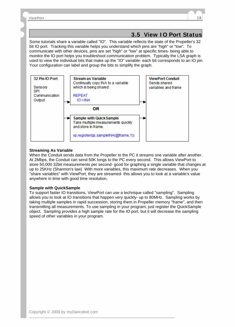
3.5 View IO Port StatusSome tutorials share a variable called "IO". This variable reflects the state of the Propeller's 32bit IO port. Tracking this variable helps you understand which pins are "high" or "low". Tocommunicate with other devices, pins are set "high" or "low" at specific times- being able tomonitor the IO port helps you troubleshoot communication problem. Typically the LSA graph isused to view the individual bits that make up the "IO" variable- each bit corresponds to an IO pin.Your configuration can label and group the bits to simplify the graph.
Streaming As VariableWhen the Conduit sends data from the Propeller to the PC it streams one variable after another.At 2Mbps, the Conduit can send 50K longs to the PC every second. This allows ViewPort tostore 50,000 32bit measurements per second- good for graphing a single variable that changes atup to 25KHz (Shannon's law) With more variables, this maximum rate decreases. When you"share variables" with ViewPort, they are streamed- this allows you to look at a variable's valueanywhere in time with good time resolution.
Sample with QuickSampleTo support faster IO transitions, ViewPort can use a technique called "sampling". Samplingallows you to look at IO transitions that happen very quickly- up to 80MHz. Sampling works bytaking multiple samples in rapid succession, storing them in Propeller memory "frame", and thentransmitting all measurements. To use sampling in your program, just register the QuickSampleobject. Sampling provides a high sample rate for the IO port, but it will decrease the samplingspeed of other variables in your program.
Copyright © 2009 by myDancebot.com
ViewPort 18
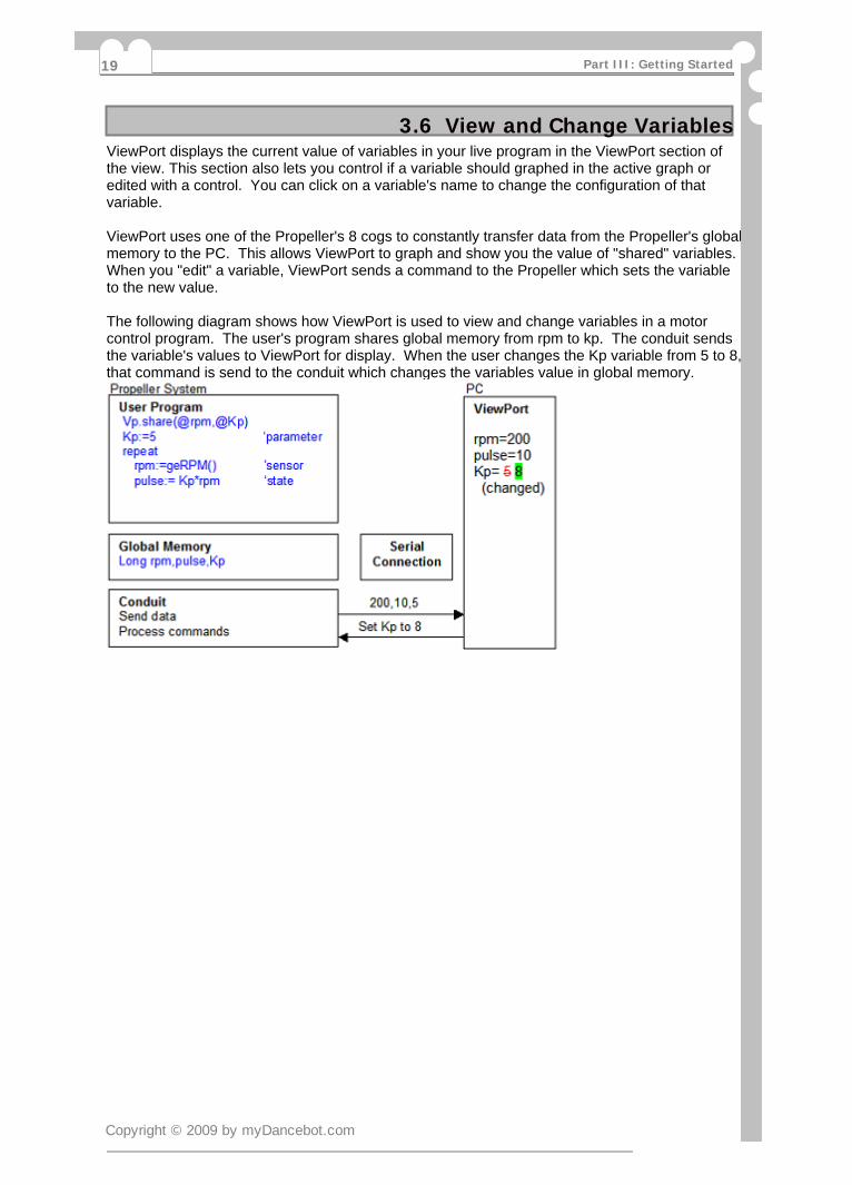
3.6 View and Change VariablesViewPort displays the current value of variables in your live program in the ViewPort section ofthe view. This section also lets you control if a variable should graphed in the active graph oredited with a control. You can click on a variable's name to change the configuration of thatvariable.
ViewPort uses one of the Propeller's 8 cogs to constantly transfer data from the Propeller's globalmemory to the PC. This allows ViewPort to graph and show you the value of "shared" variables.When you "edit" a variable, ViewPort sends a command to the Propeller which sets the variableto the new value.
The following diagram shows how ViewPort is used to view and change variables in a motorcontrol program. The user's program shares global memory from rpm to kp. The conduit sendsthe variable's values to ViewPort for display. When the user changes the Kp variable from 5 to 8,that command is send to the conduit which changes the variables value in global memory.
Copyright © 2009 by myDancebot.com
Part III: Getting Started19

3.7 Connect/DisconnectThe Connect and Stop buttons let you start or stop the connection with the Propeller. You canstill view, manipulate, and save data, but no new data will be captured while the connection isstopped.
Every time you start a connection with the Propeller, ViewPort will query the program'sconfiguration. If the program's configuration has changed (because you loaded a new program),then ViewPort will use that new configuration to it receives from the Propeller to configure itself.Configuration can also be saved and loaded as files or included in a program.
Auto-Connect/Auto-DisconnectOnly one Program on your PC can use the COM/USB port that connects the PC to the Propellerchip. Typically you'll want to use the Propeller Tool to develop new programs and use ViewPortto debug them. Auto-Connect/Disconnect makes this easy by stopping the connection when theViewPort Window is no longer active (like when you select the Propeller Tool window). Theconnection will restart when the window becomes active again (when you click on the ViewPortwindow). You can disable this behavior under "Edit/Preferences".
Copyright © 2009 by myDancebot.com
ViewPort 20

Part IVIntegrating your
Program withViewPort
ViewPort
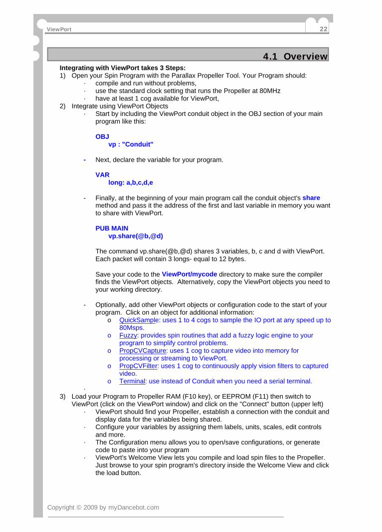
4.1 OverviewIntegrating with ViewPort takes 3 Steps:1) Open your Spin Program with the Parallax Propeller Tool. Your Program should:
· compile and run without problems,· use the standard clock setting that runs the Propeller at 80MHz· have at least 1 cog available for ViewPort,
2) Integrate using ViewPort Objects· Start by including the ViewPort conduit object in the OBJ section of your main
program like this:
OBJ vp : "Conduit"
- Next, declare the variable for your program.
VAR long: a,b,c,d,e
- Finally, at the beginning of your main program call the conduit object's sharemethod and pass it the address of the first and last variable in memory you wantto share with ViewPort.
PUB MAIN vp.share(@b,@d)
The command vp.share(@b,@d) shares 3 variables, b, c and d with ViewPort.Each packet will contain 3 longs- equal to 12 bytes.
Save your code to the ViewPort/mycode directory to make sure the compilerfinds the ViewPort objects. Alternatively, copy the ViewPort objects you need toyour working directory.
- Optionally, add other ViewPort objects or configuration code to the start of yourprogram. Click on an object for additional information:
o QuickSample: uses 1 to 4 cogs to sample the IO port at any speed up to80Msps.
o Fuzzy: provides spin routines that add a fuzzy logic engine to yourprogram to simplify control problems.
o PropCVCapture: uses 1 cog to capture video into memory forprocessing or streaming to ViewPort.
o PropCVFilter: uses 1 cog to continuously apply vision filters to capturedvideo.
o Terminal: use instead of Conduit when you need a serial terminal.·
3) Load your Program to Propeller RAM (F10 key), or EEPROM (F11) then switch toViewPort (click on the ViewPort window) and click on the "Connect" button (upper left)
· ViewPort should find your Propeller, establish a connection with the conduit anddisplay data for the variables being shared.
· Configure your variables by assigning them labels, units, scales, edit controlsand more.
· The Configuration menu allows you to open/save configurations, or generatecode to paste into your program
· ViewPort's Welcome View lets you compile and load spin files to the Propeller.Just browse to your spin program's directory inside the Welcome View and clickthe load button.
Copyright © 2009 by myDancebot.com
ViewPort 22

4.2 Integrate ViewPort into spin codeThis is a an example where we start with a simple counting program and walk through the stepsdiscussed on the previous page.
Here is a simple Spin program that counts from 0 to b using variable a:CON _clkmode = xtal1 + pll16x _xinfreq = 5_000_000OBJVAR
long a,bPUB count
b:=1000repeat
a++if a>b
a~
The program uses the standard 80MHz clock, includes no objects, and stores a and b in globalmemory. The program can easily be modified so that you can use ViewPort to monitor and adjustvariable values.
Integrate ViewPort into the ProgramAdd the lines:
vp:"Conduit"
andvp.share(@a,@b)
so your program reads:
CON _clkmode = xtal1 + pll16x _xinfreq = 5_000_000OBJ
vp:"Conduit"VAR
long a,bPUB count
vp.share(@a,@b)b:=1000repeat
a++if a>b
a~
Use the Parallax Propeller Tool to edit and save this Program to ViewPort/mycode/count.spinLoad to Propeller RAM using the F10 key.Start ViewPort and hit the "Connect" button.ViewPort should connect to your Program and graph 2 variables in the DSO mode. Learn how toconfigure ViewPort in the next step
Copyright © 2009 by myDancebot.com
Part IV: Integrating your Program with ViewPort23
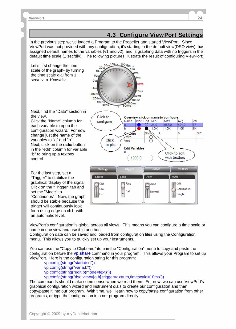
4.3 Configure ViewPort SettingsIn the previous step we've loaded a Program to the Propeller and started ViewPort. SinceViewPort was not provided with any configuration, it's starting in the default view(DSO view), hasassigned default names to the variables (v1 and v2), and is graphing data with no triggers in thedefault time scale (1 sec/div). The following pictures illustrate the result of configuring ViewPort:
Let's first change the timescale of the graph- by turningthe time scale dial from 1sec/div to 10ms/div.
Next, find the "Data" section inthe view.Click the "Name" column foreach variable to open theconfiguration wizard. For now,change just the name of thevariables to "a" and "b".Next, click on the radio buttonin the "edit" column for variable"b" to bring up a textboxcontrol.
For the last step, set a"Trigger" to stabilize thegraphical display of the signal.Click on the "Trigger" tab andset the "Mode" to"Continuous". Now, the graphshould be stable because thetrigger will continuously lookfor a rising edge on ch1- withan automatic level.
ViewPort's configuration is global across all views. This means you can configure a time scale orname in one view and use it in another.Configuration data can be saved and loaded from configuration files using the Configurationmenu. This allows you to quickly set up your instruments.
You can use the "Copy to Clipboard" item in the "Configuration" menu to copy and paste theconfiguration before the vp.share command in your program. This allows your Program to set upViewPort. Here is the configuration string for this program:
vp.config(string("start:dso"))vp.config(string("var:a,b"))vp.config(string("edit:b(mode=text)"))vp.config(string("dso:view=[a,b],trigger=a>auto,timescale=10ms"))
The commands should make some sense when we read them. For now, we can use ViewPort'sgraphical configuration wizard and instrument dials to create our configuration and thencopy/paste it into our program. With time, we'll learn how to copy/paste configuration from otherprograms, or type the configuration into our program directly.
Copyright © 2009 by myDancebot.com
ViewPort 24

4.4 Source Code for Tutorial 1{**************************************************** (C) 2008 myDanceBot.com, Inc. ** Analyze a four bit counter ** AppletImage=scope.gif *****************************************************Shows how you can analyze activity on thePropeller's pins using the Logic State Analyzer.
To use this Program with ViewPort, compile and load it into your Propeller's RAMwith the F10 key. Then start ViewPort and press the "Connect" button.
When ViewPort connects to this program, it will display a logicanalyzer view showing 6 traces. The programcontinually increments a counter and outputs the counter value to thepins of the Propeller. The first 4 traces show the pins being toggledby the counter- they're counting in binary.You can vary the speed of the counter by turning the dial in the edit section.You can change the timescale by turning the timescale dial and you can triggeron a different trace by clicking on its label. The last 2 traces represent thedata being transmitted and received over the serial connection.}CON _clkmode = xtal1 + pll16x _xinfreq = 5_000_000 'use standard 5MHz clockOBJ 'include 2 ViewPort objects: vp : "Conduit" 'transfers data to/from PC qs : "QuickSample" 'samples INA continuously in 1 cog- up to 20MspsVAR long cntr ' 'binary counter long nextCycle 'time for next increment long freq 'counter frequency- edited with ViewPort dial long frame[400] 'stores measurements of INA portpub demo vp.register(qs.sampleINA(@frame,1)) 'sample INA into <frame> array optional_configure_viewport 'optionally configure viewport's interface vp.share(@freq,@freq) 'share the <freq> variable dira[16..20]~~ 'output pulses on pins 16..20 nextCycle:=cnt+clkfreq 'initialize first cycle time repeat outa[20..16]:=(cntr+=1) 'count in binary on pins 20..16 nextCycle+=((clkfreq/freq)#> 6000 <#clkfreq/10) waitcnt(nextCycle) 'wait until next cycle- controlled by <freq> variablepub optional_configure_viewport vp.config(string("var:freq(unit=Hz,min=0,max=10000),io(bits=[cntr[16..19],30tx,31rx])")) 'share just the freq variable. it has a unit of Hz with range from 0 to 10k 'the io frame is filled by the sampleINA call- we're only interested in specific bits which 'we name: 16..19 make up the cntr, 30 is tx and 31 is rx vp.config(string("lsa:view=io,timescale=1ms,trigger=io[16]r")) 'configure the lsa graph to display the io variable with timescale set to 1ms and 'trigger set on bit 16 rising vp.config(string("edit:freq(default=5000,mode=[dial,text])")) 'configure the edit section to display a dial and text for the freq variable- defaults to 5000 vp.config(string("start:lsa")) 'start in lsa mode
Copyright © 2009 by myDancebot.com
Part IV: Integrating your Program with ViewPort25
Part VReference(Windows
Application)
ViewPort
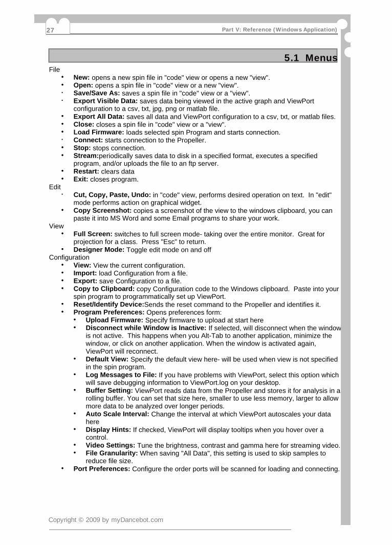
5.1 MenusFile
New: opens a new spin file in "code" view or opens a new "view".·Open: opens a spin file in "code" view or a new "view".·Save/Save As: saves a spin file in "code" view or a "view".·Export Visible Data: saves data being viewed in the active graph and ViewPort·configuration to a csv, txt, jpg, png or matlab file.Export All Data: saves all data and ViewPort configuration to a csv, txt, or matlab files.·Close: closes a spin file in "code" view or a "view".·Load Firmware: loads selected spin Program and starts connection.·Connect: starts connection to the Propeller.·Stop: stops connection.·Stream:periodically saves data to disk in a specified format, executes a specified·program, and/or uploads the file to an ftp server.Restart: clears data·Exit: closes program.·
EditCut, Copy, Paste, Undo: in "code" view, performs desired operation on text. In "edit"·mode performs action on graphical widget.Copy Screenshot: copies a screenshot of the view to the windows clipboard, you can·paste it into MS Word and some Email programs to share your work.
ViewFull Screen: switches to full screen mode- taking over the entire monitor. Great for·projection for a class. Press "Esc" to return.Designer Mode: Toggle edit mode on and off·
ConfigurationView: View the current configuration.·Import: load Configuration from a file.·Export: save Configuration to a file.·Copy to Clipboard: copy Configuration code to the Windows clipboard. Paste into your·spin program to programmatically set up ViewPort.Reset/Identify Device:Sends the reset command to the Propeller and identifies it.·Program Preferences: Opens preferences form:·
Upload Firmware: Specify firmware to upload at start here·Disconnect while Window is Inactive: If selected, will disconnect when the window·is not active. This happens when you Alt-Tab to another application, minimize thewindow, or click on another application. When the window is activated again,ViewPort will reconnect.Default View: Specify the default view here- will be used when view is not specified·in the spin program.Log Messages to File: If you have problems with ViewPort, select this option which·will save debugging information to ViewPort.log on your desktop.Buffer Setting: ViewPort reads data from the Propeller and stores it for analysis in a·rolling buffer. You can set that size here, smaller to use less memory, larger to allowmore data to be analyzed over longer periods.Auto Scale Interval: Change the interval at which ViewPort autoscales your data·hereDisplay Hints: If checked, ViewPort will display tooltips when you hover over a·control.Video Settings: Tune the brightness, contrast and gamma here for streaming video.·File Granularity: When saving "All Data", this setting is used to skip samples to·reduce file size.
Port Preferences: Configure the order ports will be scanned for loading and connecting.·
Copyright © 2009 by myDancebot.com
Part V: Reference (Windows Application)27

5.2 Menus Part 2
PluginsAdd: visits the http://mydancebot.com/viewport/plugins website to download and install·additional capabilities.Manage: get information about particular plugins or uninstall them·List of Installed Plugins: shows information for installed plugins·
DebugStart Debugging: Loads the debug enabled program and starts the debugging session·Pause: Pauses the active cog and shows the current line·Stop: Stops the debugger and connection·Step Into: Steps one instruction further·Step Over: Step one instruction/function call further·Step Out: Step out of current function·
HelpHelp Index: opens the search and browseable Help file.·PDF Manual: links to the pdf manual available at:·http://mydancebot.com/viewport/manual.pdf, suitable for printingCheck for Updates: Visits the myDanceBot website to check for an update·Register: Displays Registration screen·About: Displays information window·
Copyright © 2009 by myDancebot.com
ViewPort 28

5.3 Folder Structure
The ViewPort installer checks for a valid .net Framework installation, presents the licenseagreement and installs files as follows:
ViewPort DirectoryViewPort.exe
core applicationReadme.txt
contains information about the releaseunins000.dat/unins00.exe
uninstall filesSubdirectories:
Config.cfg files: store configuration files here
Data.txt .csv .mat .jpg .png files: save data files here.bat files: store batch files to manipulate streamed data here
myCode.spin and .binary files: develop your ViewPort compatible files here
Plugins.chm: Information about a plugin.vpc: Install/Uninstall information about a plugin
Tutorials.spin and .binary files source and compiled tutorials for the Propeller
View.xml files: layout data for each viewhierarch of image files: files used by views
Copyright © 2009 by myDancebot.com
Part V: Reference (Windows Application)29
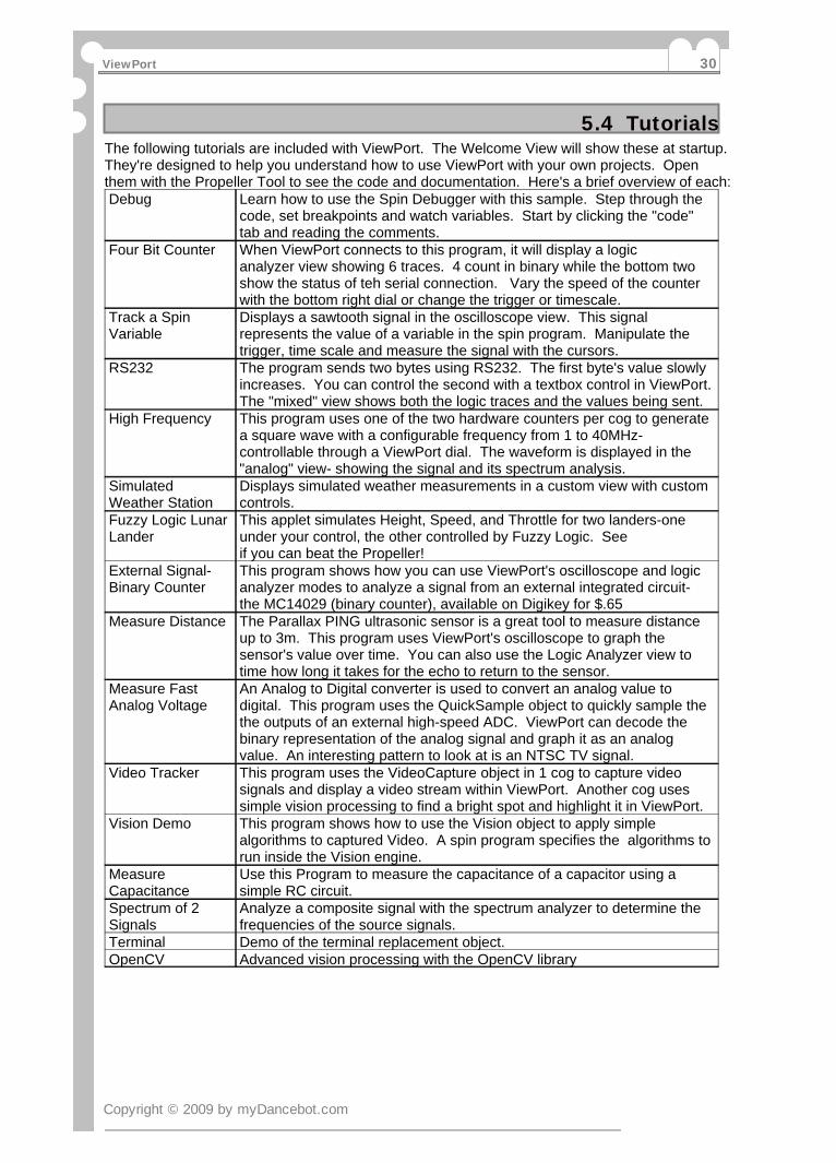
5.4 TutorialsThe following tutorials are included with ViewPort. The Welcome View will show these at startup.They're designed to help you understand how to use ViewPort with your own projects. Openthem with the Propeller Tool to see the code and documentation. Here's a brief overview of each:Debug Learn how to use the Spin Debugger with this sample. Step through the
code, set breakpoints and watch variables. Start by clicking the "code"tab and reading the comments.
Four Bit Counter When ViewPort connects to this program, it will display a logicanalyzer view showing 6 traces. 4 count in binary while the bottom twoshow the status of teh serial connection. Vary the speed of the counterwith the bottom right dial or change the trigger or timescale.
Track a SpinVariable
Displays a sawtooth signal in the oscilloscope view. This signalrepresents the value of a variable in the spin program. Manipulate thetrigger, time scale and measure the signal with the cursors.
RS232 The program sends two bytes using RS232. The first byte's value slowlyincreases. You can control the second with a textbox control in ViewPort.The "mixed" view shows both the logic traces and the values being sent.
High Frequency This program uses one of the two hardware counters per cog to generatea square wave with a configurable frequency from 1 to 40MHz-controllable through a ViewPort dial. The waveform is displayed in the"analog" view- showing the signal and its spectrum analysis.
SimulatedWeather Station
Displays simulated weather measurements in a custom view with customcontrols.
Fuzzy Logic LunarLander
This applet simulates Height, Speed, and Throttle for two landers-oneunder your control, the other controlled by Fuzzy Logic. Seeif you can beat the Propeller!
External Signal-Binary Counter
This program shows how you can use ViewPort's oscilloscope and logicanalyzer modes to analyze a signal from an external integrated circuit-the MC14029 (binary counter), available on Digikey for $.65
Measure Distance The Parallax PING ultrasonic sensor is a great tool to measure distanceup to 3m. This program uses ViewPort's oscilloscope to graph thesensor's value over time. You can also use the Logic Analyzer view totime how long it takes for the echo to return to the sensor.
Measure FastAnalog Voltage
An Analog to Digital converter is used to convert an analog value todigital. This program uses the QuickSample object to quickly sample thethe outputs of an external high-speed ADC. ViewPort can decode thebinary representation of the analog signal and graph it as an analogvalue. An interesting pattern to look at is an NTSC TV signal.
Video Tracker This program uses the VideoCapture object in 1 cog to capture videosignals and display a video stream within ViewPort. Another cog usessimple vision processing to find a bright spot and highlight it in ViewPort.
Vision Demo This program shows how to use the Vision object to apply simplealgorithms to captured Video. A spin program specifies the algorithms torun inside the Vision engine.
MeasureCapacitance
Use this Program to measure the capacitance of a capacitor using asimple RC circuit.
Spectrum of 2Signals
Analyze a composite signal with the spectrum analyzer to determine thefrequencies of the source signals.
Terminal Demo of the terminal replacement object.OpenCV Advanced vision processing with the OpenCV library
Copyright © 2009 by myDancebot.com
ViewPort 30

5.5 Connection PropertiesPortViewPort uses the Parallax Propellent module to compile spin files and manage the connectionwith the Propeller. You can configure the order ports will be scanned and which ports to skipusing the Propellent configuration screen available from the "Port Preferences" item of the"Configuration" menu.
Baud RateViewPort's default baud rate is 1MBaud- equivalent to 1 million bits/second or roughly 100,000bytes/second. This allows ViewPort to quickly transfer data back and forth to the Propeller tosupport high sampling rates as well as streaming video. Under good conditions, you canincrease the baud rate to 2MBaud using the pull-down menu next to the "Connect" button. IfViewPort complains about lost data, select a slower rate. ViewPort lite is restricted to a slowerrate of 115kbps.
Copyright © 2009 by myDancebot.com
Part V: Reference (Windows Application)31
5.6 Communication ProtocolReceiving DataThe Conduit object continually sends packets marked by out-of-band markers at the set baudrate. ViewPort discards any packets where the markers are out of alignment.
Sending Data and CommandsViewPort sends data and commands to the conduit. The conduit times the start bit to set its baudrate.
Reading ConfigurationViewPort sends a READCFG command to the conduit which returns configuration string andlength of memories being shared. ViewPort then parses the configuration data to initialize theViewPort view
Loading FirmwareViewPort opens the selected Port (defaults to AutoUSB which will try all USB-serial devices) andlook for a Propeller. If found, it issues a RESET and proceeds to load the Propeller's memorywith the selected firmware.
Detecting the PropellerViewPort issues a RESET and issues a VERSION command to the Propeller. A valid responseindicates the Propeller is on that port.
More details to come...
Copyright © 2009 by myDancebot.com
ViewPort 32
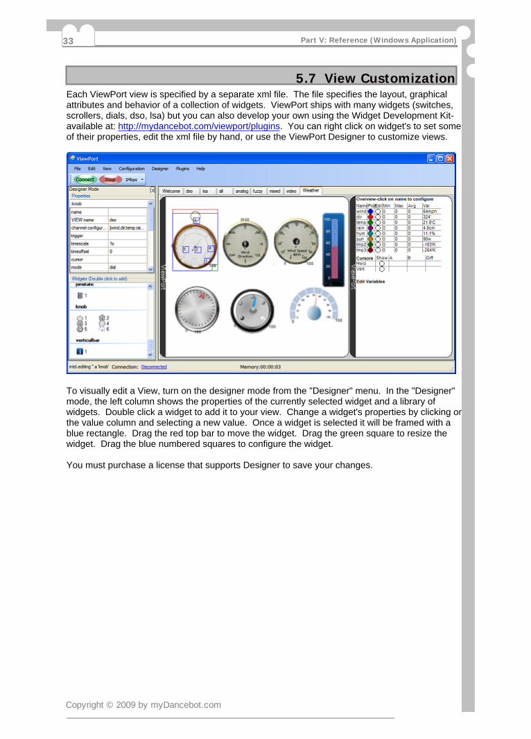
5.7 View CustomizationEach ViewPort view is specified by a separate xml file. The file specifies the layout, graphicalattributes and behavior of a collection of widgets. ViewPort ships with many widgets (switches,scrollers, dials, dso, lsa) but you can also develop your own using the Widget Development Kit-available at: http://mydancebot.com/viewport/plugins. You can right click on widget's to set someof their properties, edit the xml file by hand, or use the ViewPort Designer to customize views.
To visually edit a View, turn on the designer mode from the "Designer" menu. In the "Designer"mode, the left column shows the properties of the currently selected widget and a library ofwidgets. Double click a widget to add it to your view. Change a widget's properties by clicking onthe value column and selecting a new value. Once a widget is selected it will be framed with ablue rectangle. Drag the red top bar to move the widget. Drag the green square to resize thewidget. Drag the blue numbered squares to configure the widget.
You must purchase a license that supports Designer to save your changes.
Copyright © 2009 by myDancebot.com
Part V: Reference (Windows Application)33

5.8 Welcome View FilesTo populate the "Welcome" list, ViewPort looks for SPIN files in the active directory. Wheninstalled, this is the "tutorials" directory. You can use the "browse" button to change the activedirectory. ViewPort can compile and load files to the Propeller.If you follow the header format of the tutorials, ViewPort will include a description and image withyour spin file. The 2nd line of your spin file is used as the description and the third line specifieswhich image to use. Look at the tutorials for an example.
Of course you don't have to use ViewPort's Welcome View, you can upload to RAM or EPROMwith the Propeller Tool and then hit the "Connect" button.
Copyright © 2009 by myDancebot.com
ViewPort 34
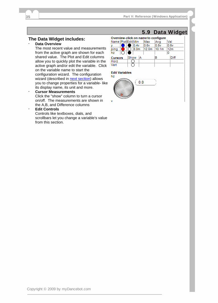
5.9 Data WidgetThe Data Widget includes:
Data Overview·The most recent value and measurementsfrom the active graph are shown for eachshared value. The Plot and Edit columnsallow you to quickly plot the variable in theactive graph and/or edit the variable. Clickon the variable name to start theconfiguration wizard. The configurationwizard (described in next section) allowsyou to change properties for a variable- likeits display name, its unit and more.Cursor Measurements·Click the "show" column to turn a cursoron/off. The measurements are shown inthe A,B, and Difference columnsEdit Controls·Controls like textboxes, dials, andscrollbars let you change a variable's valuefrom this section.
Copyright © 2009 by myDancebot.com
Part V: Reference (Windows Application)35
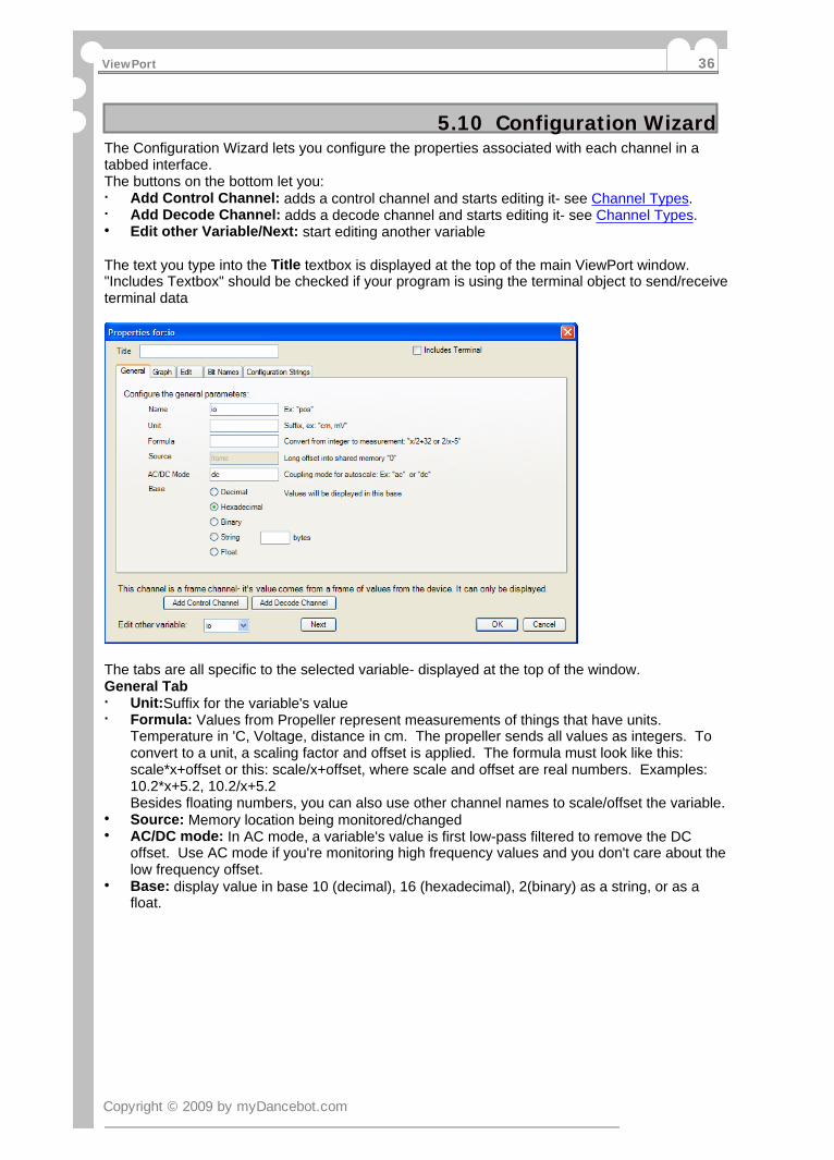
5.10 Configuration WizardThe Configuration Wizard lets you configure the properties associated with each channel in atabbed interface.The buttons on the bottom let you:
Add Control Channel: adds a control channel and starts editing it- see Channel Types.·Add Decode Channel: adds a decode channel and starts editing it- see Channel Types.·Edit other Variable/Next: start editing another variable·
The text you type into the Title textbox is displayed at the top of the main ViewPort window."Includes Textbox" should be checked if your program is using the terminal object to send/receiveterminal data
The tabs are all specific to the selected variable- displayed at the top of the window.General Tab
Unit:Suffix for the variable's value·Formula: Values from Propeller represent measurements of things that have units.·Temperature in 'C, Voltage, distance in cm. The propeller sends all values as integers. Toconvert to a unit, a scaling factor and offset is applied. The formula must look like this:scale*x+offset or this: scale/x+offset, where scale and offset are real numbers. Examples:10.2*x+5.2, 10.2/x+5.2Besides floating numbers, you can also use other channel names to scale/offset the variable.Source: Memory location being monitored/changed·AC/DC mode: In AC mode, a variable's value is first low-pass filtered to remove the DC·offset. Use AC mode if you're monitoring high frequency values and you don't care about thelow frequency offset.Base: display value in base 10 (decimal), 16 (hexadecimal), 2(binary) as a string, or as a·float.
Copyright © 2009 by myDancebot.com
ViewPort 36

5.11 Configuration Wizard Part 2Graph
Show in Graph: toggle to·include/remove from active graph.Scale: resolution/division in units.·Offset: units for bottom of graph.·
EditShow in Editor: toggle to·include/remove from the edit sectionList of Controls: choose which controls·to use for editing the variable.Min: sets the minimum value sent by·scrollbar and dial knob.Max: sets the maximum value sent by·scrollbar and dial knob.Labels: labels assigned to controls-only·used with the "slider" control.Input: the value shown on this control·can be from a different channel
Bit NamesTable of Bits and Names: label·individual bits for display in the LSAwidgetTable of Groups and Bits: label groups·of bits for display in the LSA widget
Configuration StringsGeneral: view or edit the complete·general configuration stringGraph:view or edit the complete view·configuration stringEdit :view or edit the complete edit·configuration string
Decode from Other VariableThis tab only exists for "decode·channels". Click on "Add DecodeChannel" to add one.Source Variable: decode value from this·source variableBit Start: this bit will be the lsb·Bit End: this bit will be the msb·
Copyright © 2009 by myDancebot.com
Part V: Reference (Windows Application)37

5.12 Channel TypesBesides interacting with data that map directly to variables shared in a Propeller program,ViewPort also supports frame, control and decode channels.
A Variable Channel is created when you share a variable. You can graph this data and·edit the variable's value. Sharing more variables will decrease the effective sampling rateof the streamed data.A Frame Channel is created when you register the QuickSample. Doing so will allow you·to sample the IO port at fast rates, but slow the sampling rate of the other streamedvariables channels. You can't edit the frame channel.A Decode Channel is used when the value you want to display is "embedded" in another·value. For example, when you read a binary counters value with pin 10-17 of the Propeller,the counter's value is embedded in bits 10-17 of the INA variable. A Decode Channel getsits values by decoding a source channel with set parameters- in our case- masking out bits10-17 and shifting right by 10. Since it's value is computed on the fly within ViewPort, itdoes not affect the sampling rate and you can't edit this channel.A Control Channel is used when you need to change variables in Propeller memory but·don't need to stream them back to the PC- ie parameters as opposed to sensor readings.The variables edited by control channels start with the one after the last shared variable.For example, if you allocate these variables:
main |a,b,c,dand share just a and b with this statement
vp.share(@a,@b)then the first control channel will map to variable c, and the second to variable d
Copyright © 2009 by myDancebot.com
ViewPort 38
5.13 Graph ConfigurationEach graph maintains this information:
Variables being viewed: the list of variables to be plotted by this graph. For each variable·you can specify its scale, offset and coupling.
Time scale: the horizontal resolution of the graph.·
Time offset: when triggered, this represents the offset from the trigger point. When data is·sampled, this offset is from the start of the sample. When in realtime mode, the graph labelshows the date and time. In normal mode, the offset is relative to the most recent sample-which is taken at time 0.
Trigger: You can configure each trigger separately- there are 4 modes:·
Bit Mode: Select R/F for rising/falling edge, then select the bit·
Pattern Mode: Use this mode to trigger on multiple bits. Enter a string of characters- 1·for each bit. The right most character corresponds to the least significant bit. 0=low,1=high, r=rising, f=falling, x=don't care
Value Mode: Use this mode to trigger on a rising/falling decimal value. Set a value and·choose to trigger on rise/falling edge
Expression Mode: Use this mode to trigger on matching values. Choose a qualifier and·set a value. Qualifier can be: = to equal the value, > to rise, < to fall, d to be different, gto be greater, l to be less than.
Some views include multiple graphs- this allows them to data with different variables, time scales,triggers and offsets.
Copyright © 2009 by myDancebot.com
Part V: Reference (Windows Application)39

5.14 Widget Development KitThe ViewPort Development Kit allows you to build plugins for ViewPort to let users interact withdata in new ways. Widgets have access to all of ViewPort's data, including data values, metadata about each channel, and general data. Widgets can access ViewPort controls like thetimescale selector and can send data back to the Propeller. Developers can package graphicfiles, views, dll's and a help file into a vpc plugin file for easy distribution. Users install a plugin byopening it with ViewPort.
The Kit is only made available to registered users of ViewPort + Developer.
More details available at: http://mydancebot.com/viewport/plugins
Copyright © 2009 by myDancebot.com
ViewPort 40

5.15 DSO WidgetThe oscilloscope graphs the value of one or more variables over time. You can change the timescale, time offset vertical resolution, coupling, autoscale, and trigger mode.
AutoScale automatically scales and center each trace so it fits on the screen at the right place.Of course you may override these by dragging the traces with your mouse or changing theresolution.You can move a channel trace my dragging it with the mouse. You can scroll back in time byusing the scroll bar at the bottom or dragging the grid back and forth. To change the timeresolution use the timescale control. Add and change value-based triggers by clicking/draggingjust to the left of the graph. Use cursors to measure the signal. Click the "Connect"/"Stop"buttons to start or stop the connection. Auto measurements display the signals amplitude, limits,average, period, frequency, and root mean square.
Copyright © 2009 by myDancebot.com
Part V: Reference (Windows Application)41
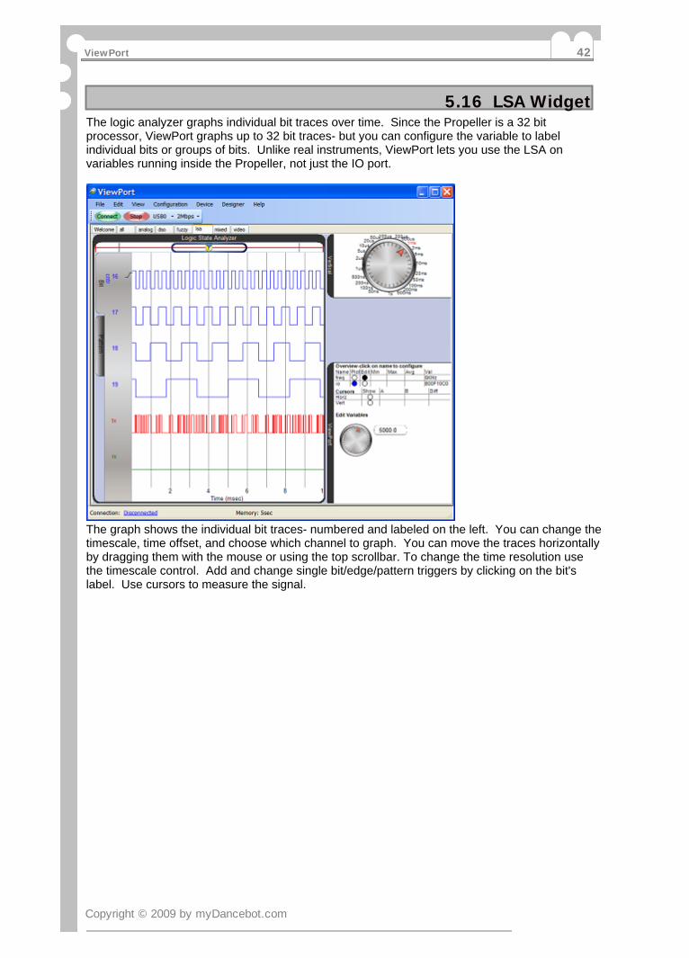
5.16 LSA WidgetThe logic analyzer graphs individual bit traces over time. Since the Propeller is a 32 bitprocessor, ViewPort graphs up to 32 bit traces- but you can configure the variable to labelindividual bits or groups of bits. Unlike real instruments, ViewPort lets you use the LSA onvariables running inside the Propeller, not just the IO port.
The graph shows the individual bit traces- numbered and labeled on the left. You can change thetimescale, time offset, and choose which channel to graph. You can move the traces horizontallyby dragging them with the mouse or using the top scrollbar. To change the time resolution usethe timescale control. Add and change single bit/edge/pattern triggers by clicking on the bit'slabel. Use cursors to measure the signal.
Copyright © 2009 by myDancebot.com
ViewPort 42

5.17 Fuzzy Logic Control Panel WidgetFuzzy Logic simplifies some control problems by making control values understandable tohumans. See: http://en.wikipedia.org/wiki/Fuzzy_system on the web, or the Fuzzy Logic Conceptssection, or the section on the Fuzzy Logic Engine Object. This page covers the Fuzzy LogicControl Panel.
When your program includes a shared fuzzy logic engine, ViewPort enables the fuzzy logiccontrol panel view. This view shows an oscillloscope on top and the overview panel on the right.The Fuzzy panel displays fuzzy maps and fuzzy rules.
Fuzzy MapsFuzzy maps are graphed on the left. In the image above, you'll see 7 maps. Each one maps avariable's value onto 5 classes. The vertical red line in each map indicates the exact value of thevariable. The area in blue indicates the proportion of membership of each class. If the area iscompletely blue, membership is 100%. If the variable's value lies between 2 classes, bothclasses will have some blue- see the 3rd map in the image above. You can change how classesare mapped in real time by clicking on the value and typing a new value.
Fuzzy RulesFuzzy rules are graphed on the right. You'll see 2 rules in the image above. Rules use 2fuzzified variables as input to a lookup table. The inputs are indicated as horizontal and verticalaxis. You can click and change the values of the lookup table to change the rules behavior.When your program is running, the yellow/orange/red areas indicate the proportion of the rulethat's firing- the red area has the highest impact, then orange, then yellow.
Copyright © 2009 by myDancebot.com
Part V: Reference (Windows Application)43

5.18 Fuzzy Logic ConceptsFuzzy Logic is a technique to efficiently solve some control problems. ViewPort comes with aGraphical Control Panel view found in the "Fuzzy" view, and a Fuzzy Logic Engine implementedin the "fuzzy.spin" object. ViewPort's fuzzy logic implementation consists of fuzzy maps, fuzzyrules, and fuzzy logic functions.
Fuzzy Maps
Fuzzy Maps "fuzzify" a number, by mapping it to 5 classes. In the image above there are 5classes to which a number can belong:
Class Minimum "Center" Class MaximumClass 0: Very negative -infinity -200 -80Class 1: Negative -200 -80 0Class 2: Zero -80 0 80Class 3: Positive 0 80 200Class 4: Very Positive 80 200 infinity
Notice that a number can belong to 1 or 2 classes. For example, -30 (as shown above) belongsmostly to the "zero" class, but also to the "negative" class. The red line indicates the exact value,the blue level shows degree of membership of the class. Only 2 parameters are required foreach map since the center for class 2 is 0 and the classes are symmetric around class 2. Theseparameters (the centers for class 3 and class 4: 80 and 200 in our example) are provided as aparameter to the "setMap" function for the "Fuzzy" spin object. They are also shown in thecontrol panel and can be edited. The fuzzy logic engine has 2 "fuzzy registers", A and B. Tofuzzify an integer into A, use "fuzzifyA(valueToBeFuzzified, mapNumber)" where mapNumber isthe number set up by the "setMap" function. "FuzzifyB" does the same for fuzzy register B. Mostof the time you will want to defuzzify the result of a fuzzy calculation with the"deFuzzify(mapNumber)" function. This maps the fuzzy register A back to a number using thespecified map. You could also call "getTopClass" which returns the class number in register Awith the highest membership:0..4
Fuzzy Rules
Fuzzy Rules allow you to control 1 output variable using 2 input variables and a lookup table.You need to specify the input variables and lookup table using the "setRule" function. The controlpanel allows you to change the "result" values in the lookup table by clicking to edit the value.Calling the "doAnd" or "doOr" functions will calculate the result by looking up all classes whichhave some fuzzy membership and applying the appropriate fuzzy logic. In the above example,posE is "very negative" and velE is mostly "zero", so the result of a "doAnd" call will be class "0".When your program is running, the red square tells you which result has the highest weight.Fuzzy logic ensures that the output function is smooth and continuous across the input space.
Fuzzy Logic FunctionsThe engine also supports boolean functions: doAnd, doOr, and doInv. doInv takes the fuzzyinverse of A and returns it into A. doAnd and doOr take the fuzzy AND/OR of registers A, B andplace the result into A.Lastly, to share the fuzzy logic engine with ViewPort, use the vp.register(f.start(@FuzzFrame))line after initializing all your fuzzy maps and rules. Then, call f.share(@FuzzFrame) once in yourcontrol loop to share the data.
Copyright © 2009 by myDancebot.com
ViewPort 44

5.19 TerminalViewPort includes a terminal widget that shows the terminal output of your program when usingthe terminal object. Entering text into the text area will send the keystrokes to the Propellerwhere they can be read in as bytes, strings, integers and floats.
Copyright © 2009 by myDancebot.com
Part V: Reference (Windows Application)45

5.20 Spectrum Analyzer WidgetUse the Spectrum Analyzer to analyze the spectral composition of a variable's values over time.Start with the Oscilloscope to ensure you signal is properly scaled and triggered, then view thesignal and its analysis on the spectrum analyzer. The spectrum analyzer displays a powerspectrum over a given frequency range in real time.
Copyright © 2009 by myDancebot.com
ViewPort 46
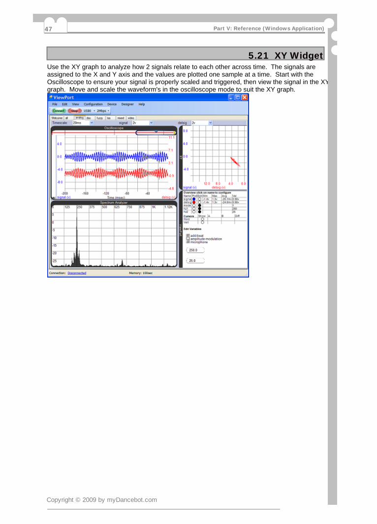
5.21 XY WidgetUse the XY graph to analyze how 2 signals relate to each other across time. The signals areassigned to the X and Y axis and the values are plotted one sample at a time. Start with theOscilloscope to ensure your signal is properly scaled and triggered, then view the signal in the XYgraph. Move and scale the waveform's in the oscilloscope mode to suit the XY graph.
Copyright © 2009 by myDancebot.com
Part V: Reference (Windows Application)47

5.22 DebuggerThe Spin Debugger greatly simplifies debugging code. It lets you stop the program at a givenpoint (a breakpoint) or pause it at the press of a button. You can step one line of code at a timewhile you're watching your variable values change in real time. The call stack and profiler tell youhow your program got to it's current state and how much time is spent in each function.
The Debugger is part of the "code" view, so start by clicking the "code" tab in the main ViewPortwindow. You should see your current spin file with familiar "Propeller Tool" syntax highlighting.
After pressing the triangular "play" button to "start debugging", you can:- set a breakpoint by clicking on the line number you wish to pause the program at. Once the cogrunning your program reaches this line, it will pause execution- resume from a breakpoint by clicking the "play" button again. To remove your breakpoint, clickthe line number again.- pause your code where it's currently executing by clicking the "pause" button.- step into functions called by a line of spin code by pressing the "step into" button- step over a line of spin code by pressing the "step over" button- step out of a function by pressing the "step out" button- view the call stack window to see which functions were called to get to the current state- the watch window shows variables you've shared with ViewPort- including their address in mainPropeller memory and their value. Click on the address to scroll the "Memory" window to thataddress. Click on the value to change it.- the profiler shows how much time is spend in different functions- the memory shows a complete snapshot of the Propeller's 32kb mainmemory- taken at each step- the command interpreter window lets you interact with the debugger:- "h": for a help listing- "set VAR=VALUE": sets variable named "VAR" to "VALUE"- "print VAR": prints the value of variable named "VAR"- "r":run until breakpoint- "s":step 1 line of spin code- "sN":step N lines of spin code- "p" : pause execution- "w VAR=<>VALUE":conditionally runs while variable "VAR" =<> "VALUE"- "u" VAR=<>VALUE":conditionally runs until variable "VAR" =<> "VALUE"- "a":animates the program, by taking ~5 steps/second- mouse over a shared variable to see it's value or change it.- load a file by clicking "File:Open" or selecting from the file browser- save a file by clicking "File:Save"- view a spin project's objects in the Object view- view a spin file's documentation by clicking the "Documentation" button- manage multiple spin files in tabs, close with the "x" button.- use any of the other ViewPort windows while you're debugging
To use the Debugger on your own programs you should:- use the 80MHz clock mode- declare vp:"Conduit" as an object- call vp.share with the address of memory you wish to watch
Copyright © 2009 by myDancebot.com
ViewPort 48

5.23 OpenCVThe OpenCV integration lets you easily experiment with state-of-the-art computer vision with yourViewPort/Propeller combination. Find x,y of faces, colored blobs, circles, textures all using spincode!OpenCV has been the leading Computer Vision library for 10 years, it was used by Stanford towin the DARPA race. Until now, it was difficult to do vision processing with OpenCV and controlreal-world devices. With the ViewPort integration, people will have the best of all worlds- easyintegration with all sorts of real world sensors and actuators with the Propeller and state of the artvision algorithms from OpenCV, all presented with a simple interface inside of ViewPort.
To get started, click on the "video" view inside of ViewPort. This will bring up the "video" viewwith a "video" panel and an "opencv" control panel. Use the "openCV" panel to control fromwhich source (image file, video file, webcam, propeller frame grabber) video should be shown.Click the "filter" tabs (edge, face, color, circle...) to apply different filters to the video. If the videohas already been filtered by the Propeller Vision Filter, it will show that result. Each "filter" tabhas additional controls- play around!For info on capturing video with the Propeller look at the VideoCapture object.For info on using a video file, visit: http://opencv.willowgarage.com/wiki/VideoCodecsFor info on filtering video with the propeller look at the Vision Filter object.If you have a webcam connected that works with other Windows applications like Skype, it shouldwork here- you may have to try different numbers in the box next to "Webcam". Try0,1,100,101,200,201...The video output will show the filtered video, the location of found objects, and the cursorslocation and value- all standardized to return numbers between 0 and 1000.
Copyright © 2009 by myDancebot.com
Part V: Reference (Windows Application)49

Part VIReference(Propeller
Objects)
ViewPort
6.1 OverviewThere are 6 components in the ViewPort library.
Conduit runs in one cog and is mandatory. It moves data back and forth to and from the·host computer and manages the ViewPort system on the Propeller.QuickSample runs in either 1 or 4 cogs and takes quick measurements of the INA port.·Fuzzy Logic Engine is a library of spin functions which provide fuzzy logic operators. It does·not use a separate cog.PropCVCapture runs in 1 cog and captures video data into an array.·PropCVFilter runs in 1 cog to apply vision filters to the memory array·Terminal is a wrapper around the Conduit object- use it instead of Conduit when you need a·terminal session as well as ViewPort.
Propeller Resource RequirementsAt minimum, 1 cog is required to integrate with ViewPort- this cog will run the ViewPort Conduitcode. Additional components may require additional cogs- as specified above. ViewPortrequires 2 Pins for serial communication with the host system. The code for ViewPort objectsrequires relatively little global memory space. However, the QuickSample, VideoCapture andVision objects require memory space for the sample measurements and video data- use thePropeller Tool to make sure you're program doesn't exceed the Propeller's memory bounds.
Copyright © 2009 by myDancebot.com
Part VI: Reference (Propeller Objects)51

6.2 ConduitYour Program must include and start this Object to use ViewPort. This Object allows you toregister additional components, share data, configure and start ViewPort.
Features:-Transfers data at up to 2Mbps Full-Duplex over a Parallax USB-Serial connection or 115Kbps over other Serial connections.-Manages configuration of variables and registration of ViewPort objects-Automatically switches between baud rates depending on ViewPort setting
Use:-Include this object in your program (MANDATORY):
Obj vp:"Conduit"
-Share Data and Start (mandatory, but must be last vp command in your program):To share data, ViewPort needs to know the location of memory to track. The sharecommand lets you specify the start and end of memory to share:vp.share(@varA,@varC) 'one cog is started to share memory between varA and varC
-Register Components (optional)If you're using other ViewPort components like QuickSample or VideoCapture, you needto register them with ViewPort:vp.register(startValue) 'the start function of each components provides the StartValue
-Send text strings to ViewPort (optional) vp.txt(ptrToBuffer,ptrToString) ptrToBuffer must point to a shared, allocated buffer ptrToString must point to a null terminated string
Configure ViewPort (optional):All configuration is optional and can be performed from within the ViewPort interface.You may configure it here to start ViewPort in a certain mode. See Configuration Stringsection for more detail- or use ViewPort to create the configuration for you.vp.config(configStr)
Copyright © 2009 by myDancebot.com
ViewPort 52
6.3 QuickSampleUse this Object to take measurements of INA at very high speeds.Users can use ViewPort to analyze those measurements alongside other variablesfrom their program.
Features:-Measure 1440 samples at 32bit up to 80MHz using 4 cogs.-Measure 360 samples at 32bit up to 20MHz using 1 cog.-Flexible timescale from seconds to nanoseconds-Edge and Pattern Triggers- can be reset by ViewPort if not Trigger found-Samples are continuously taken by 1 or 4 interleaved cogs running self modifying assemblycode.
Use:-Include this object in your program: Obj qs:"QuickSample"-Allocate memory for the INAFrame: LONG INAFrame[400] Allocate ~400 longs for the INAFrame if using 1 cog, or 1600 if using 4.-Register with ViewPort before the vp.start command vp.register(qs.sampleINA(@INAFrame,NumberOfCogs)) NumberOfCogs should be 1 cog to sample up to 20MHz, or 4 to sample up to 80MHz
Frame InternalsThe first 10 longs are configuration variables managed by ViewPort for timescale, trigger, as wellas synchronization markers. This is followed by data samples
ViewPort will update configuration parameters and restart the QuickSample cogs when:frame timescale changed·trigger changed·every now and then·
The quicksample code supports either 1 or 4 cog mode. It dynamically changes its code for eachsampling run.
Copyright © 2009 by myDancebot.com
Part VI: Reference (Propeller Objects)53
6.4 Fuzzy Logic EngineUse this Object to add a fuzzy logic engine to your program.Fuzzy Logic simplifies some control problems by making control valuesunderstandable to humans.
See the section on Fuzzy Logic Control Panel for more details on the control panel, or FuzzyLogic Concepts for additional help on basic concepts.
Features:-Easily implement fuzzy logic in your Parallax Propeller programs-Supports all fuzzy logic operators: not, or, and, fuzzify, defuzzify, andrule, orrule, topclass-Allows multiple fuzzifying maps and rulesets-Rich user interface via Viewport: variable membership is shown on maps and rulesets. Allparameters can be changed on-the-fly by clicking the number-High performance- typical fuzzy logic calculations run in less than 1ms.
Use:-Include this object in your program: Obj f:"fuzzy"-Register with ViewPort before the vp.start command vp.register(f.start(@FuzzFrame)) *Allocate ~250 longs for the FuzzFrame-Set up the mapping functions: f.setMap(MapNumber,@VariableToBeMapped,Class4,Class5) *The classes will have midpoints at(-Class5,-Class4,0,Class4,Class5)-Initialize the rules: f.setRule(RuleNumber,@Var1,@Var2,@RulePtr) *RulePtr should point to an array of 28 bytes
In your control loop:-Fuzzify your variables into the 2 Fuzzy Registers: f.fuzzifyA(varA,MapNumber) f.fuzzifyB(varB,MapNumber)-Perform your calculations: f.doOr f.doInv f.doandRule(RuleNumber)-Defuzzify the result into a variable: varC:=f.defuzzify(MapNumber)-Share data with ViewPort during development: f.share(@FuzzFrame)
Copyright © 2009 by myDancebot.com
ViewPort 54
6.5 PropCVFilterUse this Object to continuously apply vision filters to video data capturedby PropCVCapture. Spin commands are used to manipulate a vision program whichis run in assembly in its own cog.
Features:-Implements common vision filters in assembly for real time performance- up to 30fps-Combine multiple filters using a "vision program"-Supports 1, 2 or 4 video buffers-Commands: copy, invert, threshold, difference, chaos, max, pattern
Use:-Supply Propeller with video signal and capture with PropCVCapture See VideoCapture for details-Include this object in your program: Obj ve:"PropCVFilter"-Start PropCVFilter Object ve.start(@videoFrame,video#VIDEO4) 'start cog to apply vision filters-Program Vision Filters ve.filter(0,0,ve#pattern) 'draw a pattern into frame 0 ve.filter(1,0,ve#invert) 'invert pixels from 0 to 1-The Vision object will continually apply the programmed filters to incoming video
Copyright © 2009 by myDancebot.com
Part VI: Reference (Propeller Objects)55
6.6 PropCVCaptureUse this Object to capture video into an array which can be streamed to ViewPortfor display. Other programs can analyze the data and use ViewPort to displaytheir output.
Features:-Capture NTSC video up to 240h x 200v at 16 grayscales into 24kb buffer at 30fps-Supports lower resolution of 120hx100v at 16 grayscales into a 6kb buffer at 30fps-Continuously stream video, or take one snapshot-Realtime tracking of a bright blob without using memory at 30fps
Use:-Supply Propeller with video signal To generate the signal, use a "C Cam 2A" available at http://electronics123.com To sample the signal, use a "ADC08100" available at digikey. Connect the camera's NTSC composite signal to the ADC's input and connect the ADC's output to the Propeller's pins 0..3. Drive the ADC's clock with Propeller's pin 14.-Include this object in your program: Obj video:"VideoCapture"-Allocate memory for the VideoFrame: LONG VideoFrame[6000] '6000 for hi-res, 1500 for lo-res-Register with ViewPort before the vp.start command vp.register(video.start(@videoFrame,video#HIVIDEO))-Analyze VideoFrame 8 pixels are encoded into each long. Item 0 is top left. ViewPort will show the video image and can mark a box if supplied with a variable named visionXYWH- where x is top 8 bits, y is next 8, w is next 8, h is last 8.
The low-cost cmos camera which allows the Propeller to capture video at 240x240@256graylevels at 30fps and stream video to the Viewport at 240x200x16 grays is the "C Cam 2A"available at: http://www.electronics123.com/
The camera's composite NTSC signal is digitized by a high-speed ADC- like the "ADC08100".
Theory:A picture is imaged by the camera, converted to NTSC, sampled by the ADC into 8 bits and thenread as a digital value by the Propeller. The Viewport TV object running on the Propeller samplesthe INA port, finds the syncs, and "compresses" the data into a frame which is then sent to theViewport application.
Copyright © 2009 by myDancebot.com
ViewPort 56

6.7 TerminalUse this Object instead of a FullDuplexSerial derivative to quickly get started with ViewPort.ViewPort has a terminal view which let's you use your existing terminal code.
Features:* Full suite of terminal functions to receive and transmit strings and integers* Fully compatible with "Parallax Serial Terminal"* Wrapper for all Conduit functions- just use this objectUse:-Include this object in your program- replace your existing FullDuplexSerial variant: Obj vp:"Terminal"-Allocate 2 longs, these must be the first 2 longs shared by vp.share VAR long OutP,InP-Configure and share memory with ViewPort vp.config(string("start:terminal::terminal:1")) vp.share(@outP,@inP) 'use instead of vp.start(30,31,0,9600)Here's a simple program:OBJ vp: "terminal"var long OutP,InPpub main vp.config(string("start:terminal::terminal:1")) vp.share(@OutP,@InP) repeat vp.str(string("Hello World!",13))
Terminal Input/Output Functions Char(byte) Print a byte Chars(byte,count) Print a byte count times Str(stringptr) Print a string Dec(value) Print a decimal number Hex(value, digits) Print a hexadecimal number Bin(value, digits) Print a binary number DecFP(value,dp) Print a floating point number CharIn Receive a byte of data StrIn(stringptr) Receive a string StrInMax(stringptr,maxcount) Receive a string limited by maxcount DecIn Returns decimal string as value BinIn Returns binary string as value HexIn Returns hex string value as value RxCheck Check if byte received (never waits) RxFlush Flush receiver bufferTerminal Positioning Clear, ClearEnd, ClearBelow Home Position(x,y), PositionX(x), PositionY(y) NewLine, LineFeed,MoveLeft,MoveRight,MoveUp,MoveDown Tab, BackSpace,BeepViewPort Functions Share(@varA,@varC) Share memory from varA to varC with ViewPort. This lets you monitor&change them. You MUST use this function- at the start of your program, but AFTER "register" and "config" statements. Register(component,cfg) Register other components (fuzzy logic, video, quicksample..) Config(cfgstring) Configure ViewPort. CfgString can be generated by ViewPort.
Copyright © 2009 by myDancebot.com
Part VI: Reference (Propeller Objects)57
6.8 Configuration StringsYou can include configuration strings in your Propeller Program to configure ViewPort. Doing thisis optional, but gives you the power to control exactly how ViewPort will display the data fromyour program. The easiest way to create the strings is to configure ViewPort with theconfiguration wizard and instrument controls and then selecting "Copy to Clipboard" from the"Configuration" menu. You can also copy configuration code from other tutorials or type it indirectly.All configuration strings must be passed to the conduit object using the vp.config method beforethe vp.share method is called.There are 2 types of configuration sections: global and graph. The global configuration sectionsare called "var" and "edit". These let you configure the variables used in ViewPort and thevariable to be edited with controls. "Graph" sections correspond to graph widgets defined by aview's XML file. "LSA" is used by the LSA widget, "DSO" by the DSO, Spectrum Analyzer, andXY widgets. All properties have defaults, so feel free to specify only what you need.
Global Configuration Section:"var"Configure variable names and properties with "var" followed by a comma separated list ofvariable names with optional properties in parenthesis. If specified, properties are commaseparated, name=value pairs and may include:
"f": formula for calculating the display value from the Propeller's integer representation.·Either "x/scale+offset" or "scale/x+offset" where "scale" and "offset" are numbers."unit": Suffix for the variable's value·"string=x":Variable point to a string of length "x" bytes. X must be a multiple of 4. This·variable can not be the last variable shared."base": value will be displayed in this base: valid=2,10,16·"decode": to set up a decode channel using "source[startbit..endbit]"·"bits": to label individual and groups of bits using·"[<#><name>,<#><name>,<groupname>[<#><name>,<#><name>]]" where # is the bit'snumber and <name> and <groupname> start with a non-digit."mode": can be set to "log" to indicate value should be graphed in log mode·"min"/"max" to set default minimum/maximum for variable·
Example from tutorial #1:vp.config(string("var:io(bits=[cntr[16..19],30tx,31rx]),freq(unit=Hz,f=x/1000,min=0,max=10)"))Here, ViewPort will have 2 variables labeled io and freq. IO will have it's bits labeled. Freq ismeasured in "Hz" and range from 0 to 10. When the Propeller sends an integer of 1000,ViewPort will display a value of 1Hz.
"edit"Configure edit controls with "edit" followed by a comma separated list of variable names withoptional properties in parenthesis. If specified, properties are comma separated, name=valuepairs and may include:
"min"/"max" to set minimum/maximum for the control·"default": to specify the default value which is sent at connect·"label": to set the labels shown with certain edit controls·"mode": to specify which controls to sue for editing, defined by each view- but can include·one or more of: "switch,text,dial,scroll,slider". Multiple values must be comma-separated andbracketed.
Example from tutorial #1vp.config(string("edit:freq(default=5,mode=[dial,text,scroll])"))Here, ViewPort will edit 1 variable- freq. When ViewPort first connects, it will set freq to 5.ViewPort will draw a dial, textbox, and scrollbar for this channel.
Copyright © 2009 by myDancebot.com
ViewPort 58

6.9 Configuration String Part 2Graph Configuration Section:"dso","lsa", or other as defined by the view's graph widgetConfigure a graph widget with the graph's name: "dso", "lsa", or other followed by a commaseparated list of name=value pairs which may include:
"timescale"= time scale for graph·"timeoffset"= offset from trigger point or current measurement·"cursors"= sets cursor state using this format [xstate,xa,xb,ystate,ya,yb] where state can be·"on" or "off", and xa, xb, ya, yb can be 0-1000 giving position."ymode"= defines how graph range will be set: can be autoscale, manual or ranged·"view"=followed by a single variable or multiple comma-separated variables in brackets.·Each variable may have graph properties which must be comma separated in parenthesis:
"mode"=coupling mode, "ac" or "dc"·"offset"= offset to midpoint in graph·"scale"=units for a whole screen·
"trigger"=to set a trigger for the graph. There are 3 different types of triggers:·"SingleBit": this is the simplest trigger, used to trigger on one single bit in LSA mode.·Specify the variable, bit, and edge("r" or "f") you wish to trigger on:"trigger=<variable>[<bit>]<edge>""MultiBit": this allows complete flexibility in setting a binary trigger. Specify the variable·followed by a pattern string: "trigger=<variable>[<pattern>]" Each character in the stringrepresents a bit- lsb is the rightmost. Choose from "0"- bit must be low, "1" must be high,"r" must transition from low to high, "f" must transition high to low, "x" don't care. "Value": this is used to trigger on analog values. Specify the variable, operator and·value: "trigger=<variable><operator><value>" where value is a number or "auto" tospecify auto-trigger mode. Choose an operator from ">":rise, "<":fall, "=":equal, "{":lessthan, "}":greater than, "!" is different.
Example from tutorial #1: vp.config(string("lsa:view=io,timescale=1ms,trigger=io[16]r"))Here ViewPort will set up the lsa view to view the io channel. It sets the timescale to 1ms/div andstarts a trigger on the rising edge of bit 16.
Configuration String Parsing::: separates groups : separates name from value () is used for for commas-separated lists of name=values minor variables [] is used for lists of comma-separated values . is used for decimal point and bits = is used for assignment<allconfig> ::= {<cfg> "::" }<cfg> ::= <config name:string> ":" {<namevalue> ";"}<namevalue> ::= <name:string> "=" {<value> "," }<value> ::= e|<int>|<string>| <string> "(" <namevalue> ")"
Copyright © 2009 by myDancebot.com
Part VI: Reference (Propeller Objects)59
Part VIIProblem Solving
ViewPort
7.1 Problem SolvingSetup.exe doesn't run:·Make sure you have sufficient priviledges to install a new application. Also insure that yourAntivirus software is not blocking new installs.
Setup tells me to install the Microsoft .Net Framework:·This is normal. ViewPort was built on .Net Framework. It should detect if you need to installthis, and will then help you download and install it from Microsoft.
The ViewPort Application starts but doesn't Connect.·Check to make sure your Propeller IDE can successfully identify your Propeller and downloada program to the chip. Make sure your Propeller Application is starting the ViewPortConduitObject. Set the Port manually under Edit/Preferences. Switch to a slower baud rate.
If you have other problems try our forums: http://forums.mydancebot.com
Copyright © 2009 by myDancebot.com
Part VII: Problem Solving61
PartVIIIGlossary
ViewPort

8.1 GlossaryDSO: digital storage oscilloscope·LSA: logic state analyzer·GUI: guided user interface·Widget: A view is composed of widgets. Widgets can display data- like a graph or provide·control, like a time scale dial.View: ViewPort provides views for different tasks. Views display data and allow control of·Propeller programs.Conduit: The conduit is a required ViewPort object that transmits data from Propeller memory·to the PC and executes PC commands on the Propeller.Variable Channel: is created when you share a variable. You can graph this data and edit the·variable's value. Sharing more variables will decrease the effective sampling rate of thestreamed data.Frame Channel: is created when you register the QuickSample. Doing so will allow you to·sample the IO port at fast rates, but slow the sampling rate of the other streamed variableschannels. You can't edit the frame channel.Decode Channel: is used when the value you want to display is "embedded" in another value.·For example, when you read a binary counters value with pin 10-17 of the Propeller, thecounter's value is embedded in bits 10-17 of the INA variable. A Decode Channel gets itsvalues by decoding a source channel with set parameters- in our case- masking out bits 10-17 and shifting right by 10. Since it's value is computed on the fly within ViewPort, it does notaffect the sampling rate and you can't edit this channel.Control Channel: is used when you need to change variables in Propeller memory but don't·need to stream them back to the PC- ie parameters as opposed to sensor readings. Thevariables edited by control channels start with the one after the last shared variable. Forexample, if you allocate these variables:
main |a,b,c,dand share just a and b with this statement
vp.share(@a,@b)then the first control channel will map to variable c, and the second to variable d
Copyright © 2009 by myDancebot.com
Part VIII: Glossary63

Part IXHow To Buy
ViewPort

9.1 How To BuyFree EvaluationDownload a 30 day free trial version of ViewPort from our website:http://mydancebot.com/viewport
Purchase License OnlineVisit our website to securely purchase a license for the components you wish to use using GoogleCheckout or PayPal:http://mydancebot.com/viewport/register.php
Upgrade your License OnlineVisit our website with your existing license to upgrade your license to use additional components.http://mydancebot.com/viewport/upgrade.php
Distribution:Distribution of ViewPort Trial are allowed. Distribution of licenses is NOT allowed. ViewPort maynot be installed on a network.
Copyrights:ViewPort is a trademark of myDanceBot.ViewPort and all files installed by the ViewPort installer are copyrighted 2007-2009 myDanceBot.Propeller is a trademark of Parallax, Inc.
Copyright © 2009 by myDancebot.com
Part IX: How To Buy65
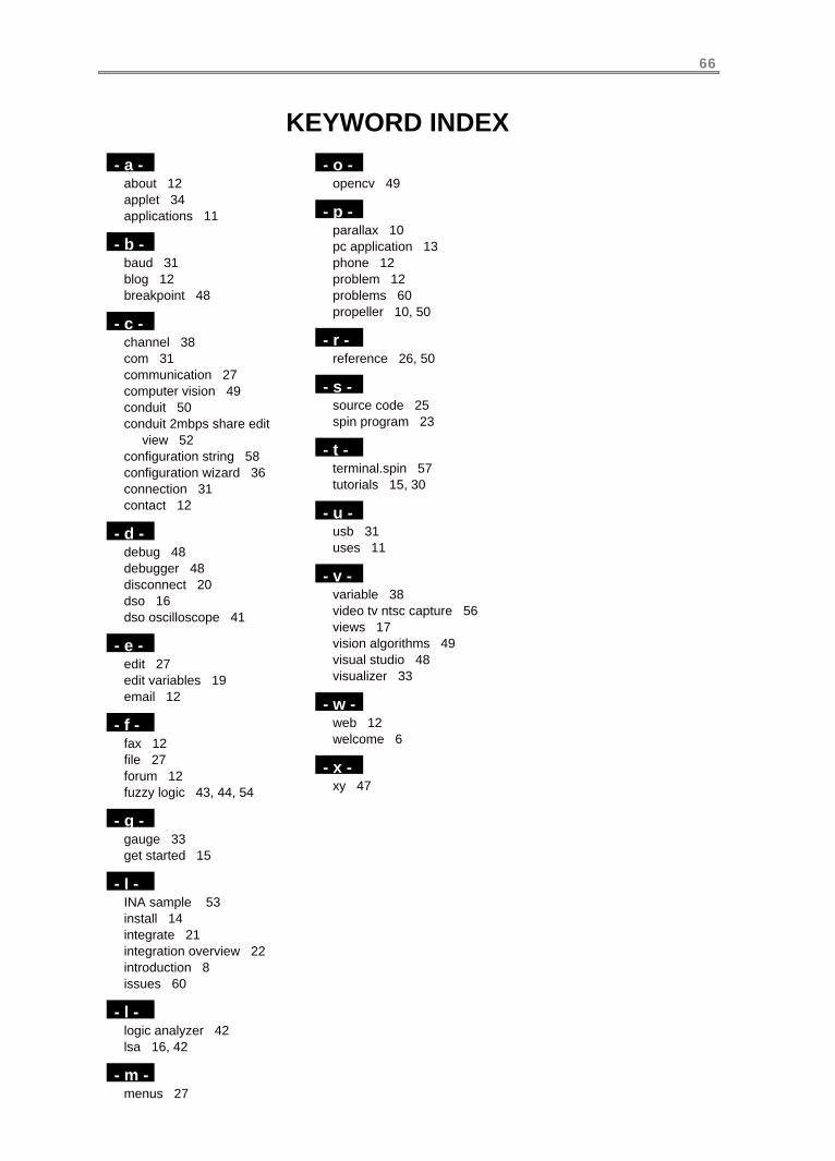
KEYWORD INDEX
66
- a -about 12applet 34applications 11
- b -baud 31blog 12breakpoint 48
- c -channel 38com 31communication 27computer vision 49conduit 50conduit 2mbps share edit view 52configuration string 58configuration wizard 36connection 31contact 12
- d -debug 48debugger 48disconnect 20dso 16dso oscilloscope 41
- e -edit 27edit variables 19email 12
- f -fax 12file 27forum 12fuzzy logic 43, 44, 54
- g -gauge 33get started 15
- I -INA sample 53install 14integrate 21integration overview 22introduction 8issues 60
- l -logic analyzer 42lsa 16, 42
- m -menus 27
- o -opencv 49
- p -parallax 10pc application 13phone 12problem 12problems 60propeller 10, 50
- r -reference 26, 50
- s -source code 25spin program 23
- t -terminal.spin 57tutorials 15, 30
- u -usb 31uses 11
- v -variable 38video tv ntsc capture 56views 17vision algorithms 49visual studio 48visualizer 33
- w -web 12welcome 6
- x -xy 47