· Web viewNo load current at nominal tap position as percent of rated current @ ONAF base :...
89
Schedule of Guaranteed Characteristics
Transcript of · Web viewNo load current at nominal tap position as percent of rated current @ ONAF base :...

Schedule of Guaranteed Characteristics

Nile Basin Initiative – Nile Equatorial Lakes Subsidiary Action ProgramInterconnection of Electric Grids of Nile Equatorial Lakes CountriesBidding Document – Lot B: Extension of the Lessos Substation for Kenya-Uganda Power Interconnection
Table of Contents
Power Transformer (220/132/11 kV, 90 MVA)....................................................................................4
132 kV General Purpose Circuit Breaker.........................................................................................11
220 kV General Purpose Circuit Breaker.........................................................................................14
132 kV Disconnector......................................................................................................................... 17
220 kV Disconnector......................................................................................................................... 19
132 kV Current Transformer.............................................................................................................21
220 kV Current Transformer.............................................................................................................22
132 kV Capacitive Voltage Transformer..........................................................................................23
220 kV Capacitive Voltage Transformer..........................................................................................24
220 kV Line Trap................................................................................................................................ 25
Lightning Arrester............................................................................................................................. 26
220 kV Shunt Reactor, 10 MVAr........................................................................................................27
220 kV Internally Fused Shunt Capacitor Bank...............................................................................30
12 kV Neutral Reactor........................................................................................................................ 33
Digital Multiplex and Optical Line Termination System (SDH)......................................................35
Emission of the Equipment (Substation Environment)..................................................................38
Immunity of the Equipment (Substation Environment)..................................................................38
VoIP System....................................................................................................................................... 40
Digital Control and Monitoring System...........................................................................................43
Bay Control Unit................................................................................................................................ 45
Tele Protection Equipment...............................................................................................................48
Line Differential Relay, Protection "A"............................................................................................49
Distance Relay, Protection "B".........................................................................................................53
Transformer Protection..................................................................................................................... 56
Bus Bar Differential Protection.........................................................................................................58
Energy Meter...................................................................................................................................... 60
Batteries and Dual Charger...............................................................................................................61
A.C. Distribution Panel...................................................................................................................... 61
D.C Distribution Panel....................................................................................................................... 63
Control, Protection, Signaling and Meter Panel..............................................................................64
Part 2 : Section VI – Employer’s RequirementsSchedule of Guaranteed Characteristics Page 2 of 75
Nile Basin Initiative – Nile Equatorial Lakes Subsidiary Action ProgramInterconnection of Electric Grids of Nile Equatorial Lakes CountriesBidding Document – Lot B: Extension of the Lessos Substation for Kenya-Uganda Power Interconnection
Low Voltage Power Cable................................................................................................................. 66
Aluminum Bus Bar............................................................................................................................ 68
Post Insulator..................................................................................................................................... 69
11 kV and 33 kV High Voltage Power Cable....................................................................................70
11 kV Metal – Clad Switchboard.......................................................................................................72
Diesel Generator................................................................................................................................ 73
Schedule of Special Tools................................................................................................................74
Part 2 : Section VI – Employer’s RequirementsSchedule of Guaranteed Characteristics Page 3 of 75
Nile Basin Initiative – Nile Equatorial Lakes Subsidiary Action ProgramInterconnection of Electric Grids of Nile Equatorial Lakes CountriesBidding Document – Lot B: Extension of the Lessos Substation for Kenya-Uganda Power Interconnection
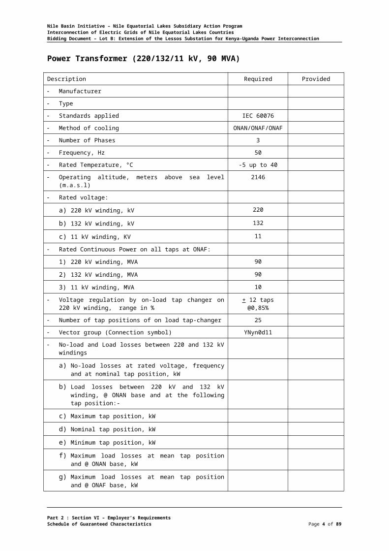
Power Transformer (220/132/11 kV, 90 MVA)
Description Required Provided
Manufacturer
Type
Standards applied IEC 60076
Method of cooling ONAN/ONAF/ONAF
Number of Phases 3
Frequency, Hz 50
Rated Temperature, °C -5 up to 40
Operating altitude, meters above sea level (m.a.s.l) 2146
Rated voltage:
a) 220 kV winding, kV 220
b) 132 kV winding, kV 132
c) 11 kV winding, KV 11
Rated Continuous Power on all taps at ONAF:
1) 220 kV winding, MVA 90
2) 132 kV winding, MVA 90
3) 11 kV winding, MVA 10
Voltage regulation by on-load tap changer on 220 kV winding, range in %
+ 12 taps @0,85%
Number of tap positions of on load tap-changer 25
Vector group (Connection symbol) YNyn0d11
No-load and Load losses between 220 and 132 kV windings
a) No-load losses at rated voltage, frequency and at nominal tap position, kW
b) Load losses between 220 kV and 132 kV winding, @ ONAN base and at the following tap position:-
c) Maximum tap position, kW
d) Nominal tap position, kW
e) Minimum tap position, kW
f) Maximum load losses at mean tap position and @ ONAN base, kW
g) Maximum load losses at mean tap position and @ ONAF base, kW
h) Total losses at mean tap position and @ ONAN base, kW
i) Total losses at mean tap position and @ ONAF base, kW
j) Total losses at tap giving maximum losses @ ONAN base, kW
k) Total losses at tap giving maximum losses @ ONAF base, kW
No-load and Load losses between 220 and 11 kV windings
Part 2 : Section VI – Employer’s RequirementsSchedule of Guaranteed Characteristics Page 4 of 75

Nile Basin Initiative – Nile Equatorial Lakes Subsidiary Action ProgramInterconnection of Electric Grids of Nile Equatorial Lakes CountriesBidding Document – Lot B: Extension of the Lessos Substation for Kenya-Uganda Power Interconnection
Description Required Provided
a) No-load losses at rated voltage, frequency and at nominal tap position, kW
b) Load losses between 220 kV and 11 kV winding, @ ONAN base and at the following tap position:
Maximum tap position, kW
Nominal tap position, kW
Minimum tap position, kW
c) Maximum load losses at mean tap position and @ ONAN base, kW
d) Maximum load losses at mean tap position and @ ONAF base, kW
e) Total losses at mean tap position and @ ONAN base, kW
f) Total losses at mean tap position and @ ONAF base, kW
g) Total losses at tap giving maximum losses @ ONAN base, kW
h) Total losses at tap giving maximum losses @ ONAF base, kW
Efficiency referred to 75 °C at rated voltage tapping and at :
a) 100% rated output and unity power factor, % > 99.5
b) 75% rated output and unity power factor, % > 99.5
c) 50% rated output and unity power factor, % > 99.5
d) 25% rated output and unity power factor, % > 99.5
e) 100% rated output and 0.8 power factor, % > 99.5
f) 75% rated output and 0.8 power factor, % > 99.5
g) 50% rated output and 0.8 power factor, % > 99.5
h) 25% rated output and 0.8 power factor, % > 99.5
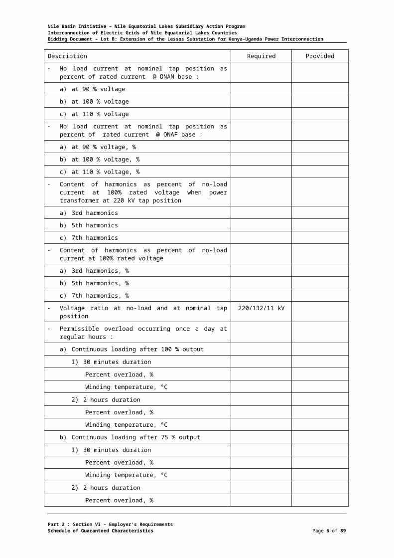
No load current at nominal tap position as percent of rated current @ ONAN base :
a) at 90 % voltage
b) at 100 % voltage
c) at 110 % voltage
No load current at nominal tap position as percent of rated current @ ONAF base :
a) at 90 % voltage, %
b) at 100 % voltage, %
c) at 110 % voltage, %
Content of harmonics as percent of no-load current at 100% rated voltage when power transformer at 220 kV tap position
a) 3rd harmonics
b) 5th harmonics
c) 7th harmonics
Content of harmonics as percent of no-load current at 100% rated voltage
a) 3rd harmonics, %
Part 2 : Section VI – Employer’s RequirementsSchedule of Guaranteed Characteristics Page 5 of 75
Nile Basin Initiative – Nile Equatorial Lakes Subsidiary Action ProgramInterconnection of Electric Grids of Nile Equatorial Lakes CountriesBidding Document – Lot B: Extension of the Lessos Substation for Kenya-Uganda Power Interconnection
Description Required Provided
b) 5th harmonics, %
c) 7th harmonics, %
Voltage ratio at no-load and at nominal tap position 220/132/11 kV
Permissible overload occurring once a day at regular hours :
a) Continuous loading after 100 % output
1) 30 minutes duration
Percent overload, %
Winding temperature, °C
2) 2 hours duration
Percent overload, %
Winding temperature, °C
b) Continuous loading after 75 % output
1) 30 minutes duration
Percent overload, %
Winding temperature, °C
2) 2 hours duration
Percent overload, %
Winding temperature, °C
c) Continuous loading after 50 % output
1) 30 minutes duration
Percent overload, %
Winding temperature, °C
2) 2 hours duration
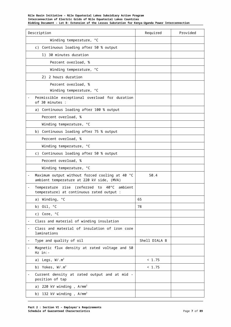
Percent overload, %Winding temperature, °C
Permissible exceptional overload for duration of 30 minutes :
a) Continuous loading after 100 % output
Percent overload, %
Winding temperature, °C
b) Continuous loading after 75 % output
Percent overload, %
Winding temperature, °C
c) Continuous loading after 50 % output
Percent overload, %
Winding temperature, °C
Maximum output without forced cooling at 40 °C ambient temperature at 220 kV side, (MVA)
50.4
Temperature rise (referred to 40°C ambient temperature) at continuous rated output :
a) Winding, °C 65
b) Oil, °C 78
Part 2 : Section VI – Employer’s RequirementsSchedule of Guaranteed Characteristics Page 6 of 75
Nile Basin Initiative – Nile Equatorial Lakes Subsidiary Action ProgramInterconnection of Electric Grids of Nile Equatorial Lakes CountriesBidding Document – Lot B: Extension of the Lessos Substation for Kenya-Uganda Power Interconnection
Description Required Provided
c) Core, °C
Class and material of winding insulation
Class and material of insulation of iron core laminations
Type and quality of oil Shell DIALA B
Magnetic flux density at rated voltage and 50 Hz in:-
a) Legs, W/.m2 < 1.75
b) Yokes, W/.m2 < 1.75
Current density at rated output and at mid - position of tap
a) 220 kV winding , A/mm2
b) 132 kV winding , A/mm2
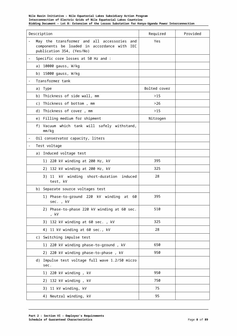
May the transformer and all accessories and components be loaded in accordance with IEC publication 354, (Yes/No)
Yes
Specific core losses at 50 Hz and :
a) 10000 gauss, W/kg
b) 15000 gauss, W/kg
Transformer tank
a) Type Bolted cover
b) Thickness of side wall, mm >15
c) Thickness of bottom , mm >26
d) Thickness of cover , mm >15
e) Filling medium for shipment Nitrogen
f) Vacuum which tank will safely withstand, mm/kg
Oil conservator capacity, liters
Test voltage
a) Induced voltage test
1) 220 kV winding at 200 Hz, kV 395
2) 132 kV winding at 200 Hz, kV 325
3) 11 kV winding short-duration induced test, kV 28
b) Separate source voltages test
1) Phase-to-ground 220 kV winding at 60 sec. , kV 395
2) Phase-to-phase 220 kV winding at 60 sec. , kV 510
3) 132 kV winding at 60 sec. , kV 325
4) 11 kV winding at 60 sec., kV 28
c) Switching impulse test
1) 220 kV winding phase-to-ground , kV 650
2) 220 kV winding phase-to-phase , kV 950
d) Impulse test voltage full wave 1.2/50 micro sec.
1) 220 kV winding , kV 950
2) 132 kV winding , kV 750
3) 11 kV winding, kV 75
Part 2 : Section VI – Employer’s RequirementsSchedule of Guaranteed Characteristics Page 7 of 75
Nile Basin Initiative – Nile Equatorial Lakes Subsidiary Action ProgramInterconnection of Electric Grids of Nile Equatorial Lakes CountriesBidding Document – Lot B: Extension of the Lessos Substation for Kenya-Uganda Power Interconnection
Description Required Provided
4) Neutral winding, kV 95
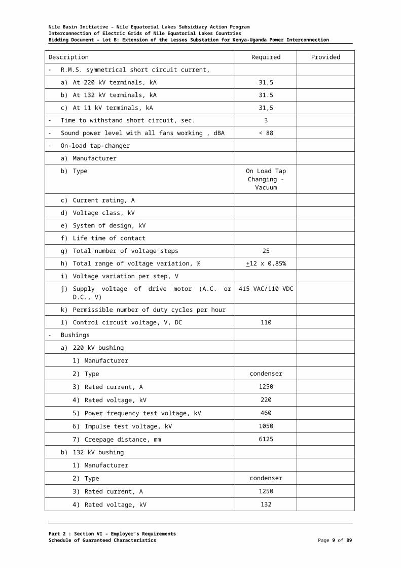
R.M.S. symmetrical short circuit current,
a) At 220 kV terminals, kA 31,5
b) At 132 kV terminals, kA 31.5
c) At 11 kV terminals, kA 31,5
Time to withstand short circuit, sec. 3
Sound power level with all fans working , dBA < 88
On-load tap-changer
a) Manufacturer
b) Type On Load Tap Changing - Vacuum
c) Current rating, A
d) Voltage class, kV
e) System of design, kV
f) Life time of contact
g) Total number of voltage steps 25
h) Total range of voltage variation, % +12 x 0,85%
i) Voltage variation per step, V
j) Supply voltage of drive motor (A.C. or D.C., V) 415 VAC/110 VDC
k) Permissible number of duty cycles per hour
l) Control circuit voltage, V, DC 110
Bushings
a) 220 kV bushing
1) Manufacturer
2) Type condenser
3) Rated current, A 1250
4) Rated voltage, kV 220
5) Power frequency test voltage, kV 460
6) Impulse test voltage, kV 1050
7) Creepage distance, mm 6125
b) 132 kV bushing
1) Manufacturer
2) Type condenser
3) Rated current, A 1250
4) Rated voltage, kV 132
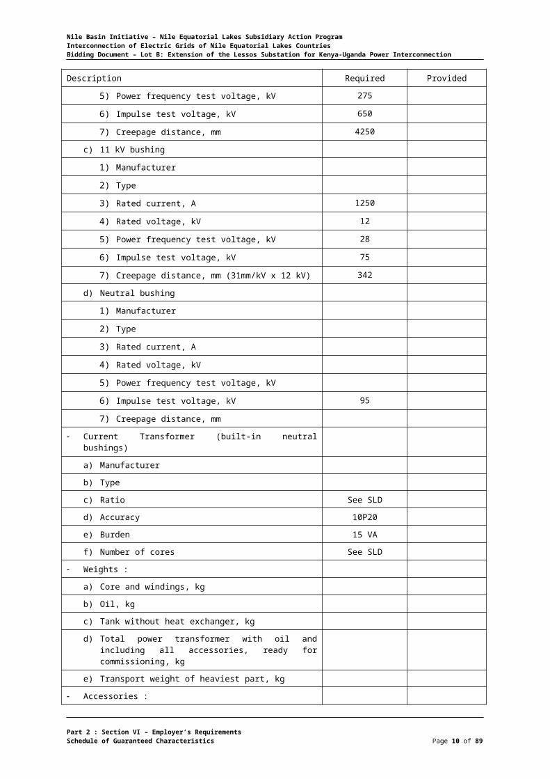
5) Power frequency test voltage, kV 275
6) Impulse test voltage, kV 650
7) Creepage distance, mm 4250
c) 11 kV bushing
1) Manufacturer
Part 2 : Section VI – Employer’s RequirementsSchedule of Guaranteed Characteristics Page 8 of 75
Nile Basin Initiative – Nile Equatorial Lakes Subsidiary Action ProgramInterconnection of Electric Grids of Nile Equatorial Lakes CountriesBidding Document – Lot B: Extension of the Lessos Substation for Kenya-Uganda Power Interconnection
Description Required Provided
2) Type
3) Rated current, A 1250
4) Rated voltage, kV 12
5) Power frequency test voltage, kV 28
6) Impulse test voltage, kV 75
7) Creepage distance, mm (31mm/kV x 12 kV) 342
d) Neutral bushing
1) Manufacturer
2) Type
3) Rated current, A
4) Rated voltage, kV
5) Power frequency test voltage, kV
6) Impulse test voltage, kV 95
7) Creepage distance, mm
Current Transformer (built-in neutral bushings)
a) Manufacturer
b) Type
c) Ratio See SLD
d) Accuracy 10P20
e) Burden 15 VA
f) Number of cores See SLD
Weights :
a) Core and windings, kg
b) Oil, kg
c) Tank without heat exchanger, kg
d) Total power transformer with oil and including all accessories, ready for commissioning, kg
e) Transport weight of heaviest part, kg
Accessories :
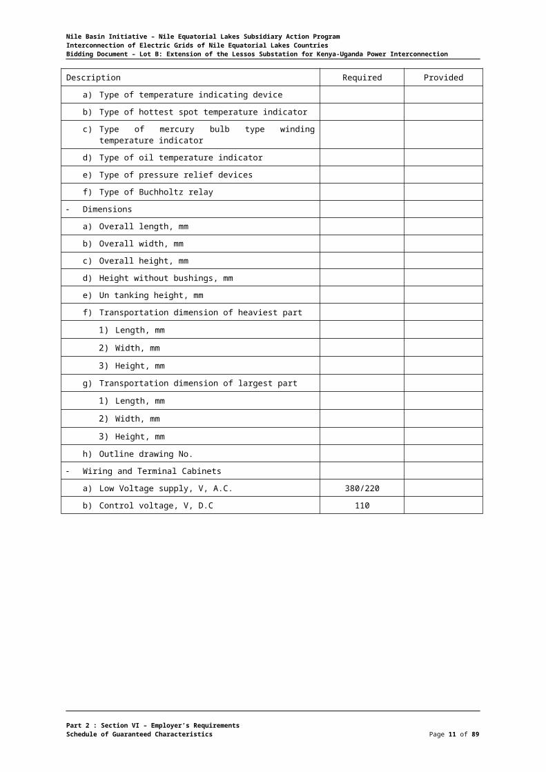
a) Type of temperature indicating device
b) Type of hottest spot temperature indicator
c) Type of mercury bulb type winding temperature indicator
d) Type of oil temperature indicator
e) Type of pressure relief devices
f) Type of Buchholtz relay
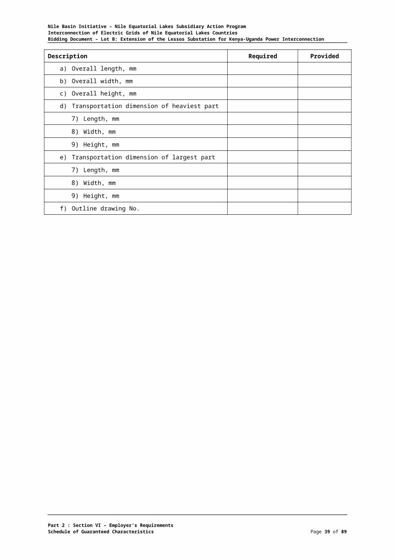
Dimensions
a) Overall length, mm
b) Overall width, mm
c) Overall height, mm
d) Height without bushings, mm
Part 2 : Section VI – Employer’s RequirementsSchedule of Guaranteed Characteristics Page 9 of 75
Nile Basin Initiative – Nile Equatorial Lakes Subsidiary Action ProgramInterconnection of Electric Grids of Nile Equatorial Lakes CountriesBidding Document – Lot B: Extension of the Lessos Substation for Kenya-Uganda Power Interconnection
Description Required Provided
e) Un tanking height, mm
f) Transportation dimension of heaviest part
1) Length, mm
2) Width, mm
3) Height, mm
g) Transportation dimension of largest part
1) Length, mm
2) Width, mm
3) Height, mm
h) Outline drawing No.
Wiring and Terminal Cabinets
a) Low Voltage supply, V, A.C. 380/220
b) Control voltage, V, D.C 110
Part 2 : Section VI – Employer’s RequirementsSchedule of Guaranteed Characteristics Page 10 of 75
Nile Basin Initiative – Nile Equatorial Lakes Subsidiary Action ProgramInterconnection of Electric Grids of Nile Equatorial Lakes CountriesBidding Document – Lot B: Extension of the Lessos Substation for Kenya-Uganda Power Interconnection
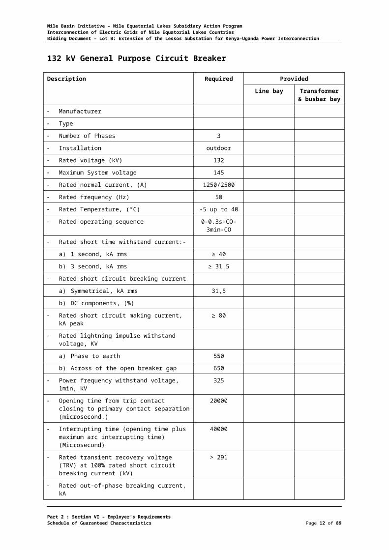
132 kV General Purpose Circuit Breaker
Description Required Provided
Line bay Transformer & busbar bay
Manufacturer
Type
Number of Phases 3
Installation outdoor
Rated voltage (kV) 132
Maximum System voltage 145
Rated normal current, (A) 1250/2500
Rated frequency (Hz) 50
Rated Temperature, (°C) -5 up to 40
Rated operating sequence 0-0.3s-CO-3min-CO
Rated short time withstand current:-
a) 1 second, kA rms ≥ 40
b) 3 second, kA rms ≥ 31.5
Rated short circuit breaking current
a) Symmetrical, kA rms 31,5
b) DC components, (%)
Rated short circuit making current, kA peak ≥ 80
Rated lightning impulse withstand voltage, KV
a) Phase to earth 550
b) Across of the open breaker gap 650
Power frequency withstand voltage, 1min, kV 325
Opening time from trip contact closing to primary contact separation (microsecond.)
20000
Interrupting time (opening time plus maximum arc interrupting time) (Microsecond)
40000
Rated transient recovery voltage (TRV) at 100% rated short circuit breaking current (kV)
> 291
Rated out-of-phase breaking current, kA
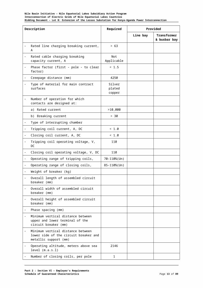
Rated line charging breaking current, A > 63
Rated cable charging breaking capacity current, A Not Applicable
Phase factor (first - pole - to clear factor) < 1.5
Creepage distance (mm) 4250
Type of material for main contract surfaces Silver plated copper
Number of operation for which contacts are designed at:
a) Rated current >10,000
b) Breaking current > 30
Part 2 : Section VI – Employer’s RequirementsSchedule of Guaranteed Characteristics Page 11 of 75
Nile Basin Initiative – Nile Equatorial Lakes Subsidiary Action ProgramInterconnection of Electric Grids of Nile Equatorial Lakes CountriesBidding Document – Lot B: Extension of the Lessos Substation for Kenya-Uganda Power Interconnection
Description Required Provided
Line bay Transformer & busbar bay
Type of interrupting chamber
Tripping coil current, A, DC < 1.0
Closing coil current, A, DC < 1.0
Tripping coil operating voltage, V, DC 110
Closing coil operating voltage, V, DC 110
Operating range of tripping coils, 70-110%(Un)
Operating range of closing coils, 85-110%(Un)
Weight of breaker (kg)
Overall length of assembled circuit breaker (mm)
Overall width of assembled circuit breaker (mm)
Overall height of assembled circuit breaker (mm)
Phase spacing (mm)
Minimum vertical distance between upper and lower terminal of the circuit breaker (mm)
Minimum vertical distance between lower side of the circuit breaker and metallic support (mm)
Operating altitude, meters above sea level (m.a.s.l)
2146
Number of closing coils, per pole 1
Number of tripping coils, per pole 2
Operating mechanism
a) Type, spring operated (Yes/No) yes
b) Number of poles per breaker 1 for line bay and 3 for
transformer and bus bar
Rated auxiliary supply voltage
a) Motor voltage, V 110 V, DC
b) Opening and closing control circuit voltage, V, DC
110 V, DC
c) Heating and lighting, V, AC 240
Number of auxiliary switch contacts
a) Contacts normally open ≥ 10
b) Contacts normally closed ≥ 10
Local electrical control with two pushbuttons (Yes/No)
yes
Local / remote switch, (Yes/No) yes
Anti pumping relay, (Yes/No) yes
Insulating gas SF6
a) Rated pressure SF6 at 200C, bar
b) Signal loss of SF6 at 200C, bar Not critical
Part 2 : Section VI – Employer’s RequirementsSchedule of Guaranteed Characteristics Page 12 of 75
Nile Basin Initiative – Nile Equatorial Lakes Subsidiary Action ProgramInterconnection of Electric Grids of Nile Equatorial Lakes CountriesBidding Document – Lot B: Extension of the Lessos Substation for Kenya-Uganda Power Interconnection
Description Required Provided
Line bay Transformer & busbar bay
c) General lockout at 200C, bar Not critical
d) Leakage rate of SF6 per annum, % < 5.0
e) Mass of SF6 gas, kg
Standards applied IEC 62271-100
Manufacturer's catalogues designation of complete circuit breaker
Catalogue No. of operating mechanism
Part 2 : Section VI – Employer’s RequirementsSchedule of Guaranteed Characteristics Page 13 of 75

Nile Basin Initiative – Nile Equatorial Lakes Subsidiary Action ProgramInterconnection of Electric Grids of Nile Equatorial Lakes CountriesBidding Document – Lot B: Extension of the Lessos Substation for Kenya-Uganda Power Interconnection
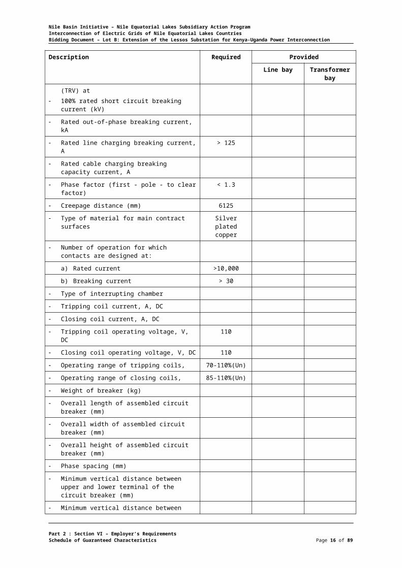
220 kV General Purpose Circuit Breaker
Description Required Provided
Line bay Transformer bay
Manufacturer
Type
Number of Phases 3
Installation Outdoor
Rated voltage (kV) 220
Maximum System voltage 245
Rated normal current, (A) 1250
Rated frequency (Hz) 50
Rated Temperature, (°C) -5 up to 40
Rated operating sequence 0-0.3s-CO-3min-CO
Rated short time withstand current:-
a) 1 second, kA rms ≥ 40
b) 3 second, kA rms ≥ 31.5
Rated short circuit breaking current
a) Symmetrical, kA rms 31,5
b) DC components, (%)
Rated short circuit making current, kA peak ≥ 80
Rated lightning impulse withstand voltage, KV
a) Phase to earth 1050
b) Across of the open breaker gap 1175
Power frequency withstand voltage, 1min, kV 460
Opening time from trip contact closing to primary contact separation (microsecond.)
Interrupting time (opening time plus maximum arc interrupting time) (Microsecond)
Closing time from moment the coil becomes energized to contact make (microsecond)
Rated transient recovery voltage (TRV) at 100% rated short circuit breaking current (kV)
> 364
Rated out-of-phase breaking current, kA
Rated line charging breaking current, A > 125
Rated cable charging breaking capacity current, A
Phase factor (first - pole - to clear factor) < 1.3
Creepage distance (mm) 6125
Type of material for main contract surfaces Silver plated copper
Number of operation for which contacts are designed at:
Part 2 : Section VI – Employer’s RequirementsSchedule of Guaranteed Characteristics Page 14 of 75

Nile Basin Initiative – Nile Equatorial Lakes Subsidiary Action ProgramInterconnection of Electric Grids of Nile Equatorial Lakes CountriesBidding Document – Lot B: Extension of the Lessos Substation for Kenya-Uganda Power Interconnection
Description Required Provided
Line bay Transformer bay
a) Rated current >10,000
b) Breaking current > 30
Type of interrupting chamber
Tripping coil current, A, DC
Closing coil current, A, DC
Tripping coil operating voltage, V, DC 110
Closing coil operating voltage, V, DC 110
Operating range of tripping coils, 70-110%(Un)
Operating range of closing coils, 85-110%(Un)
Weight of breaker (kg)
Overall length of assembled circuit breaker (mm)
Overall width of assembled circuit breaker (mm)
Overall height of assembled circuit breaker (mm)
Phase spacing (mm)
Minimum vertical distance between upper and lower terminal of the circuit breaker (mm)
Minimum vertical distance between lower side of the circuit breaker and metallic support (mm)
Operating altitude, meters above sea level (m.a.s.l)
2146
Number of closing coils, per pole 1
Number of tripping coils, per pole 2
Operating mechanism
a) Type, spring operated (Yes/No) yes
b) Number of poles per breaker 1 for line bay and 3 for
transformer and bus bar
Rated auxiliary supply voltage
a) Motor voltage, V 110 V, DC
b) Opening and closing control circuit voltage, V, DC
110 V, DC
c) Heating and lighting, V, AC 220
Number of auxiliary switch contacts
a) Contacts normally open ≥ 10
b) Contacts normally closed ≥ 10
Local electrical control with two pushbuttons (Yes/No)
yes
Local / remote switch, (Yes/No) yes
Anti pumping relay, (Yes/No) yes
Insulating gas SF6
Part 2 : Section VI – Employer’s RequirementsSchedule of Guaranteed Characteristics Page 15 of 75
Nile Basin Initiative – Nile Equatorial Lakes Subsidiary Action ProgramInterconnection of Electric Grids of Nile Equatorial Lakes CountriesBidding Document – Lot B: Extension of the Lessos Substation for Kenya-Uganda Power Interconnection
Description Required Provided
Line bay Transformer bay
a) Rated pressure SF6 at 200C, bar
b) Signal loss of SF6 at 200C, bar
c) General lockout at 200C, bar
d) Leakage rate of SF6 per annum, %
e) Mass of SF6 gas, kg
Standards applied IEC 62271-100
Manufacturer's catalogues designation of complete circuit breaker
Catalogue No. of operating mechanism
Part 2 : Section VI – Employer’s RequirementsSchedule of Guaranteed Characteristics Page 16 of 75

Nile Basin Initiative – Nile Equatorial Lakes Subsidiary Action ProgramInterconnection of Electric Grids of Nile Equatorial Lakes CountriesBidding Document – Lot B: Extension of the Lessos Substation for Kenya-Uganda Power Interconnection
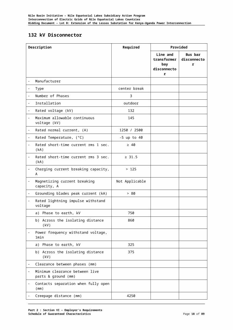
132 kV Disconnector
Description Required Provided
Line and transformer
bay disconnector
Bus bar disconnector
Manufacturer
Type center break
Number of Phases 3
Installation outdoor
Rated voltage (kV) 132
Maximum allowable continuous voltage (kV) 145
Rated normal current, (A) 1250 / 2500
Rated Temperature, (°C) -5 up to 40
Rated short-time current rms 1 sec. (kA) ≥ 40
Rated short-time current rms 3 sec. (kA) ≥ 31.5
Charging current breaking capacity, A > 125
Magnetizing current breaking capacity, A Not Applicable
Grounding blades peak current (kA) > 80
Rated lightning impulse withstand voltage
a) Phase to earth, kV 750
b) Across the isolating distance (kV) 860
Power frequency withstand voltage, 1min
a) Phase to earth, kV 325
b) Across the isolating distance (kV) 375
Clearance between phases (mm)
Minimum clearance between live parts & ground (mm)
Contacts separation when fully open (mm)
Creepage distance (mm) 4250
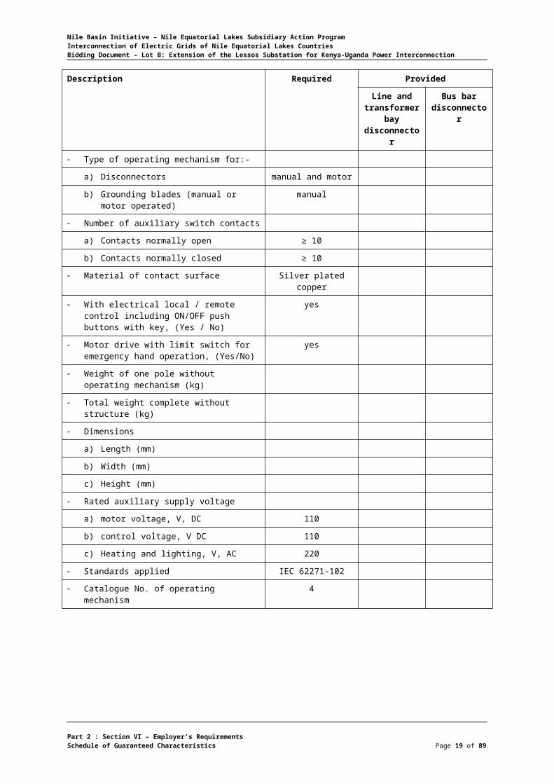
Type of operating mechanism for:-
a) Disconnectors manual and motor
b) Grounding blades (manual or motor operated)
manual
Number of auxiliary switch contacts
a) Contacts normally open ≥ 10
b) Contacts normally closed ≥ 10
Material of contact surface Silver plated copper
With electrical local / remote control including ON/OFF push buttons with key, (Yes / No)
yes
Motor drive with limit switch for emergency hand operation, (Yes/No)
yes
Weight of one pole without operating
Part 2 : Section VI – Employer’s RequirementsSchedule of Guaranteed Characteristics Page 17 of 75
Nile Basin Initiative – Nile Equatorial Lakes Subsidiary Action ProgramInterconnection of Electric Grids of Nile Equatorial Lakes CountriesBidding Document – Lot B: Extension of the Lessos Substation for Kenya-Uganda Power Interconnection
Description Required Provided
Line and transformer
bay disconnector
Bus bar disconnector
mechanism (kg)
Total weight complete without structure (kg)
Dimensions
a) Length (mm)
b) Width (mm)
c) Height (mm)
Rated auxiliary supply voltage
a) motor voltage, V, DC 110
b) control voltage, V DC 110
c) Heating and lighting, V, AC 220
Standards applied IEC 62271-102
Catalogue No. of operating mechanism 4
Part 2 : Section VI – Employer’s RequirementsSchedule of Guaranteed Characteristics Page 18 of 75
Nile Basin Initiative – Nile Equatorial Lakes Subsidiary Action ProgramInterconnection of Electric Grids of Nile Equatorial Lakes CountriesBidding Document – Lot B: Extension of the Lessos Substation for Kenya-Uganda Power Interconnection
220 kV Disconnector
Description Required Provided
Line and transformer bay
disconnector
Bus bar disconnector
Manufacturer
Type (line and transformer bay /busbar) center break
Number of Phases 3
Installation outdoor
Rated voltage (kV) 220
Maximum allowable continuous voltage (kV)
245
Rated normal current, (A) 1250 / 2500
Rated Temperature, (°C) -5 up to 40
Rated short-time current rms 1 sec. (kA) ≥ 40
Rated short-time current rms 3 sec. (kA) ≥ 31.5
Charging current breaking capacity, A > 125
Magnetizing current breaking capacity, A Not Applicable
Grounding blades peak current (kA) > 80
Rated lightning impulse withstand voltage
a) Phase to earth, kV 1050
b) Across the isolating distance (kV) 1200
Power frequency withstand voltage, 1min
a) Phase to earth, kV 460
b) Across the isolating distance (kV) 530
Clearance between phases (mm)
Minimum clearance between live parts & ground (mm)
Contacts separation when fully open (mm)
Creepage distance (mm) 6125
Type of operating mechanism for:-
a) Disconnectors manual and motor
b) Grounding blades (manual or motor operated)
manual
Number of auxiliary switch contacts
a) Contacts normally open ≥ 10
b) Contacts normally closed ≥ 10
Material of contact surface Silver plated copper
Part 2 : Section VI – Employer’s RequirementsSchedule of Guaranteed Characteristics Page 19 of 75

Nile Basin Initiative – Nile Equatorial Lakes Subsidiary Action ProgramInterconnection of Electric Grids of Nile Equatorial Lakes CountriesBidding Document – Lot B: Extension of the Lessos Substation for Kenya-Uganda Power Interconnection
Description Required Provided
Line and transformer bay
disconnector
Bus bar disconnector
With electrical local / remote control including ON/OFF push buttons with key (Yes / No)
yes
Motor drive with limit switch for emergency hand operation (Yes/No)
yes
Weight of one pole without operating mechanism (kg)
Total weight complete without structure (kg)
Dimensions
a) Length (mm)
b) Width (mm)
c) Height (mm)
Rated auxiliary supply voltage
a) motor voltage, VDC 110
b) control voltage, VDC 110
c) Heating and lighting, VAC 220
Standards applied IEC 62271-102
Catalogue No. of operating mechanism
Part 2 : Section VI – Employer’s RequirementsSchedule of Guaranteed Characteristics Page 20 of 75

Nile Basin Initiative – Nile Equatorial Lakes Subsidiary Action ProgramInterconnection of Electric Grids of Nile Equatorial Lakes CountriesBidding Document – Lot B: Extension of the Lessos Substation for Kenya-Uganda Power Interconnection
132 kV Current Transformer
Description Required Provided
Line bay Transformer bay
Bus bar coupler bay
Manufacturer
Type
Number of Phases 3
Installation outdoor
Insulating material oil/paper
Rated Voltage (kV) 132
Rated Temperature, (°C) -5 up to 40
Rated current, primary (A)
a) Line bay 300-600
b) Transformer bay 300-600
c) Bus bar coupler bay 300-600
Rated current, Secondary (A) 1
Number of cores 5
Rated burden for metering core (VA) See note 1
Rated burden for protection core (VA) ≥ 30
Accuracy class for metering core ≤ 0.2 S
Accuracy class for protection core 5P/10P
Saturation factor for metering core Fs ≥ 5
Creepage distance, (mm) 4250
Saturation factor for protection core ≥ 30
Permissible continuous over load (%)
Rated short-time current rms 1sec.(kA) ≥ 31.5
Dynamic current (kA) ≥ 80
Lightning Impulse withstand voltage (kV), 750
Power frequency withstand voltage 1-min, kV
325
Overall dimensions (mm)
Weight (kg)
Standard applied IEC 60044-1
Note 1: Rated Burden must be determined by the Contractor and summit to Client for approval
Part 2 : Section VI – Employer’s RequirementsSchedule of Guaranteed Characteristics Page 21 of 75

Nile Basin Initiative – Nile Equatorial Lakes Subsidiary Action ProgramInterconnection of Electric Grids of Nile Equatorial Lakes CountriesBidding Document – Lot B: Extension of the Lessos Substation for Kenya-Uganda Power Interconnection
220 kV Current Transformer
Description Required Provided
Line bay Transformer bay
Bus bar coupler bay
Manufacturer
Type
Number of Phases 3
Installation outdoor
Insulating material oil/paper
Rated Voltage (kV) 220
Rated Temperature, (°C) -5 up to 40
Rated current, primary (A)
a) Line bay 400-800
b) Transformer bay 400-800
c) Bus bar coupler bay 400-800
Rated current, Secondary (A) 1
Number of cores 5
Rated burden for metering core (VA) See note 1
Rated burden for protection core (VA) ≥ 30
Accuracy class for metering core ≤ 0.2 S
Accuracy class for protection core 10P
Saturation factor for metering core Fs ≤ 5
Creepage distance, (mm) 6125
Saturation factor for protection core ≥ 30
Permissible continuous over load (%)
Rated short-time current rms 1sec.(kA) ≥ 31.5
Dynamic current (kA) ≥ 80
Lightning Impulse withstand voltage (kV), 1050
Power frequency withstand voltage 1-min, kV
460
Overall dimensions (mm)
Weight (kg)
Standard applied IEC 60044-1
Note 1: Rated Burden must be determined by the Contractor and summit to Client for approval
Part 2 : Section VI – Employer’s RequirementsSchedule of Guaranteed Characteristics Page 22 of 75

Nile Basin Initiative – Nile Equatorial Lakes Subsidiary Action ProgramInterconnection of Electric Grids of Nile Equatorial Lakes CountriesBidding Document – Lot B: Extension of the Lessos Substation for Kenya-Uganda Power Interconnection
132 kV Capacitive Voltage Transformer
Description Required Provided
Manufacturer
Type
Number of Phases 3
Installation outdoor
Highest system voltage, kV 145
Rated Temperature, (°C) -5 up to 40
Insulating material paper/oil
Rated primary voltage, (kV) 132/√3
Rated voltage, winding 1, (V) 110/√3
Rated voltage, winding 2, (V) 110/√3
Number of windings 2
Rated burden, winding 1, (VA) 100
Rated burden, winding 2, (VA) 100
Rated voltage factor
Maximum allowable (thermal) burden at continuous services, (VA)
> 150
Metering class for secondary winding 1 0,2 S
Protection accuracy class for secondary winding 1 3 P
Minimum clearance between live parts (mm)
Lightning Impulse withstand voltage (kV) 750
Power frequency withstand voltage 1-min (kV) 325
Minimum creepage distance (mm) 4250
Overall dimensions (mm)
Weight (kg)
Standard applied IEC 60044-5
Part 2 : Section VI – Employer’s RequirementsSchedule of Guaranteed Characteristics Page 23 of 75

Nile Basin Initiative – Nile Equatorial Lakes Subsidiary Action ProgramInterconnection of Electric Grids of Nile Equatorial Lakes CountriesBidding Document – Lot B: Extension of the Lessos Substation for Kenya-Uganda Power Interconnection
220 kV Capacitive Voltage Transformer
Description Required Provided
Manufacturer
Type
Number of Phases 3
Installation outdoor
Highest system voltage, kV 245
Rated Temperature, (°C) -5 up to 40
Insulating material paper/oil
Rated primary voltage, (kV) 220/√3
Rated voltage, winding 1, (V) 110/√3
Rated voltage, winding 2, (V) 110/√3
Number of windings 2
Rated burden, winding 1, (VA) 100
Rated burden, winding 2, (VA) 100
Rated voltage factor
Maximum allowable (thermal) burden at continuous services, (VA)
> 150
Metering class for secondary winding 1 0,2 S
Protection accuracy class for secondary winding 1 3 P
Protection accuracy class for secondary winding 2 3 P
Minimum clearance between live parts (mm)
Lightning Impulse withstand voltage (kV) 1050
Power frequency withstand voltage 1-min (kV) 460
Minimum creepage distance (mm) 6125
Overall dimensions (mm)
Weight (kg)
Standard applied IEC 60044-5
Part 2 : Section VI – Employer’s RequirementsSchedule of Guaranteed Characteristics Page 24 of 75

Nile Basin Initiative – Nile Equatorial Lakes Subsidiary Action ProgramInterconnection of Electric Grids of Nile Equatorial Lakes CountriesBidding Document – Lot B: Extension of the Lessos Substation for Kenya-Uganda Power Interconnection
220 kV Line Trap
Description Required Provided
Manufacturer
Type
Installation outdoor
Highest system voltage, kV 245
Standard applied IEC 60353
Part 2 : Section VI – Employer’s RequirementsSchedule of Guaranteed Characteristics Page 25 of 75

Nile Basin Initiative – Nile Equatorial Lakes Subsidiary Action ProgramInterconnection of Electric Grids of Nile Equatorial Lakes CountriesBidding Document – Lot B: Extension of the Lessos Substation for Kenya-Uganda Power Interconnection
Lightning Arrester
Description Required Provided
220 kV 132 kV 220 kV 132kV
Manufacturer
Type
Installation outdoor outdoor
Rated voltage of arrester (kV) 192 120
TOV capacity:
a) for 1 second, kVrms ≥ 222 ≥ 139
b) for 10 second, kVrms ≥ 211 ≥ 132
Max. permissible line to ground voltage (kV)
Power frequency withstand voltage, 1 min., kV
≥ 460 ≥ 325
Impulse voltage at (1.2/50 microsecond) 1050 750
Residual voltage at (8/20 microsecond) and at 10 kA, (kV)
≤ 452 ≤ 311
Residual voltage at (30/60 microsecond) and at 1,0 kA, (kV)
≤ 381 ≤ 257
Rated discharge current (kA) 10 10
Maximum discharge current (kA)
Creepage distance (mm) 6125 3625
Overall dimensions (mm) (height)
Overall weight (kg)
Max. residual voltage with current wave of
(30/70 micro sec.) at 1 kA (kV)
Energy capability
a) Line discharge class (IEC) 3 3
b) 2 impulses, as per IEC 99-4, kJ/kV, Ur
7,8 7,8
c) Pressure relief withstand
Catalogues No.
Standards applied IEC60099-4
IEC60099-4
Note 1: The Contractor shall undertake insulation coordination studies to demonstrate the rating and location of lightning arresters are adequate.
Part 2 : Section VI – Employer’s RequirementsSchedule of Guaranteed Characteristics Page 26 of 75

Nile Basin Initiative – Nile Equatorial Lakes Subsidiary Action ProgramInterconnection of Electric Grids of Nile Equatorial Lakes CountriesBidding Document – Lot B: Extension of the Lessos Substation for Kenya-Uganda Power Interconnection
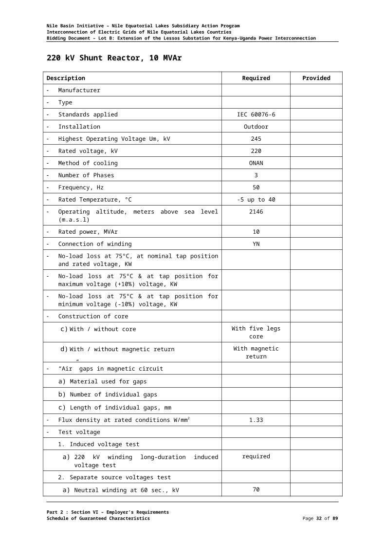
220 kV Shunt Reactor, 10 MVAr
Description Required Provided
Manufacturer
Type
Standards applied IEC 60076-6
Installation Outdoor
Highest Operating Voltage Um, kV 245
Rated voltage, kV 220
Method of cooling ONAN
Number of Phases 3
Frequency, Hz 50
Rated Temperature, °C -5 up to 40
Operating altitude, meters above sea level (m.a.s.l) 2146
Rated power, MVAr 10
Connection of winding YN
No-load loss at 75°C, at nominal tap position and rated voltage, KW
No-load loss at 75°C & at tap position for maximum voltage (+10%) voltage, KW
No-load loss at 75°C & at tap position for minimum voltage (-10%) voltage, KW
Construction of core
c) With / without core With five legs core
d) With / without magnetic return With magnetic return
“Air” gaps in magnetic circuit
a) Material used for gaps
b) Number of individual gaps
c) Length of individual gaps, mm
Flux density at rated conditions W/mm2 1.33
Test voltage
1. Induced voltage test
a) 220 kV winding long-duration induced voltage test required
2. Separate source voltages test
a) Neutral winding at 60 sec., kV 70
3. Switching impulse test
a) 220 kV winding phase-to-ground switching impulse test, kV
750
b) 220 kV winding phase-to-phase switching impulse test, kV
950
4. Impulse test voltage full wave 1.2/50 micro sec.
a) 220 kV winding, kV 950
Part 2 : Section VI – Employer’s RequirementsSchedule of Guaranteed Characteristics Page 27 of 75

Nile Basin Initiative – Nile Equatorial Lakes Subsidiary Action ProgramInterconnection of Electric Grids of Nile Equatorial Lakes CountriesBidding Document – Lot B: Extension of the Lessos Substation for Kenya-Uganda Power Interconnection
Description Required Provided
b) Neutral winding, kV 170
Sound power level at rated conditions, LWAI, dBA < 77
RMS Symmetrical short circuit at 220 kV terminals, KA 31.5
Maximum output at 40°C ambient temperature, (MVAr) 10
Temperature rise (referred to 40°C ambient temperature) at continuous rated output:
Bushings
e) 220 kV bushing
8) Manufacturer
9) Type
10) Rated current, A 800
11) Rated voltage, kV 220
12) Power frequency test voltage, kV 460
13) Impulse test voltage, kV 1050
14) Creepage distance, mm 5500
15) Minimum distance between phases, mm 2600
f) Low voltage bushing
8) Manufacturer
9) Type
10) Rated current, A 1250
11) Rated voltage, kV 36
12) Power frequency test voltage, kV 70
13) Impulse test voltage, kV 170
14) Creepage distance, mm 825
Type and quality of oil Shell DIALA B
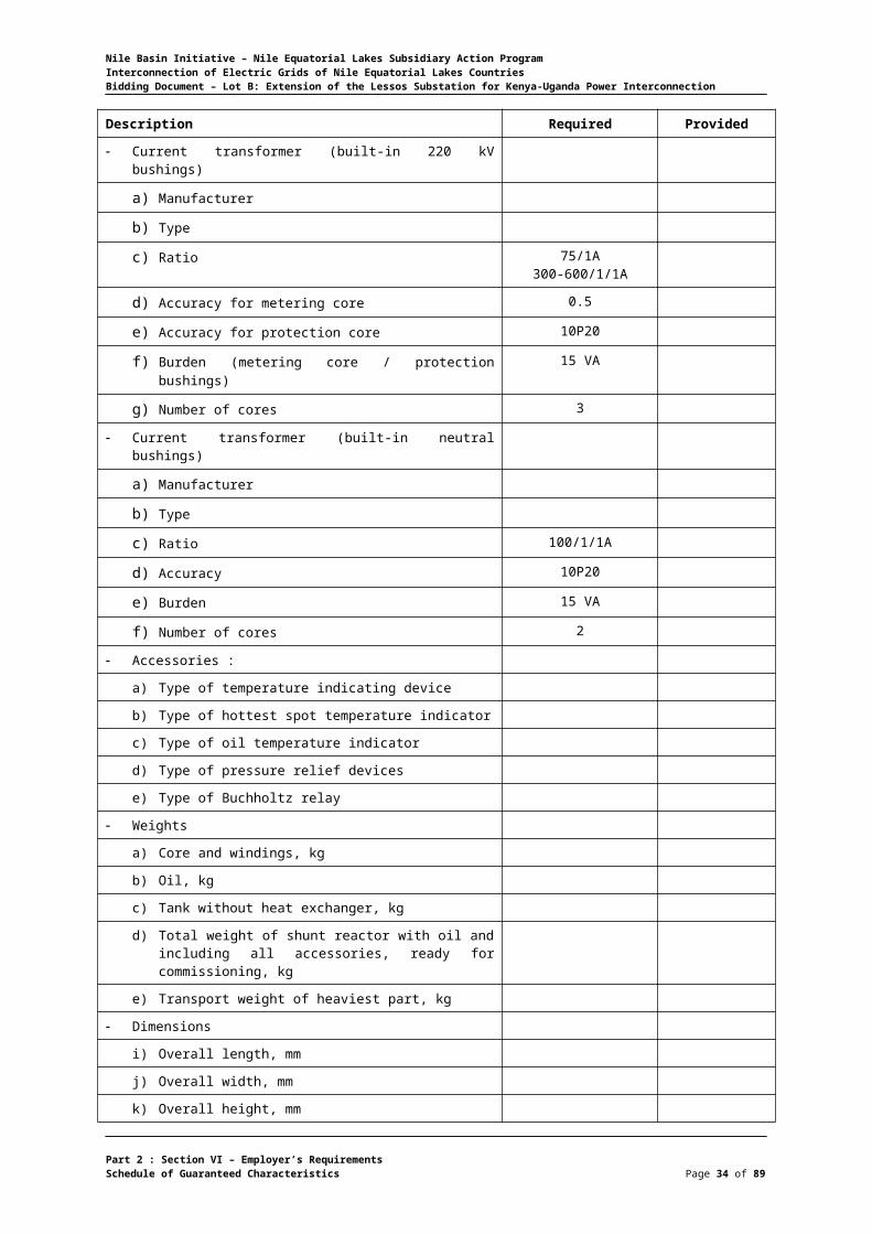
Current transformer (built-in 220 kV bushings)
a) Manufacturer
b) Type
c) Ratio 75/1A300-600/1/1A
d) Accuracy for metering core 0.5
e) Accuracy for protection core 10P20
f) Burden (metering core / protection bushings) 15 VA
g) Number of cores 3
Current transformer (built-in neutral bushings)
a) Manufacturer
b) Type
c) Ratio 100/1/1A
d) Accuracy 10P20
Part 2 : Section VI – Employer’s RequirementsSchedule of Guaranteed Characteristics Page 28 of 75

Nile Basin Initiative – Nile Equatorial Lakes Subsidiary Action ProgramInterconnection of Electric Grids of Nile Equatorial Lakes CountriesBidding Document – Lot B: Extension of the Lessos Substation for Kenya-Uganda Power Interconnection
Description Required Provided
e) Burden 15 VA
f) Number of cores 2
Accessories :
a) Type of temperature indicating device
b) Type of hottest spot temperature indicator
c) Type of oil temperature indicator
d) Type of pressure relief devices
e) Type of Buchholtz relay
Weights
a) Core and windings, kg
b) Oil, kg
c) Tank without heat exchanger, kg
d) Total weight of shunt reactor with oil and including all accessories, ready for commissioning, kg
e) Transport weight of heaviest part, kg
Dimensions
i) Overall length, mm
j) Overall width, mm
k) Overall height, mm
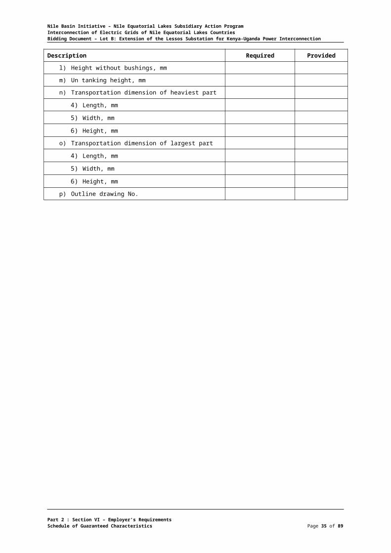
l) Height without bushings, mm
m) Un tanking height, mm
n) Transportation dimension of heaviest part
4) Length, mm
5) Width, mm
6) Height, mm
o) Transportation dimension of largest part
4) Length, mm
5) Width, mm
6) Height, mm
p) Outline drawing No.
Part 2 : Section VI – Employer’s RequirementsSchedule of Guaranteed Characteristics Page 29 of 75

Nile Basin Initiative – Nile Equatorial Lakes Subsidiary Action ProgramInterconnection of Electric Grids of Nile Equatorial Lakes CountriesBidding Document – Lot B: Extension of the Lessos Substation for Kenya-Uganda Power Interconnection
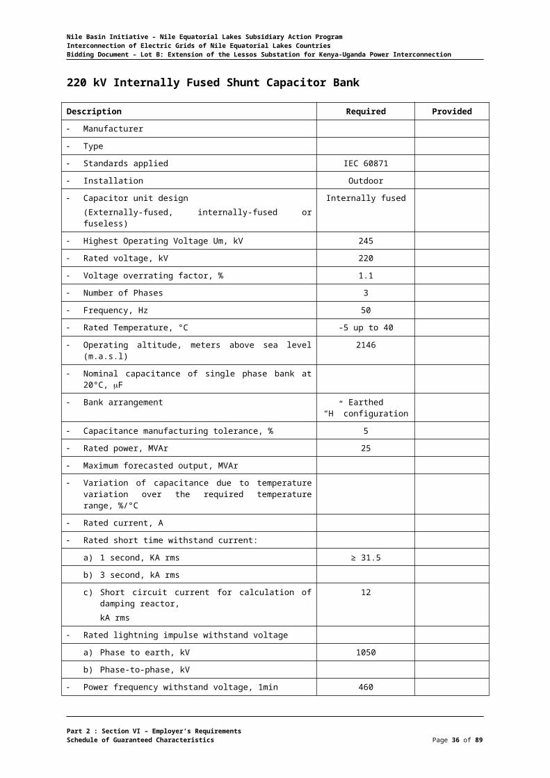
220 kV Internally Fused Shunt Capacitor Bank
Description Required Provided
Manufacturer
Type
Standards applied IEC 60871
Installation Outdoor
Capacitor unit design(Externally-fused, internally-fused or fuseless)
Internally fused
Highest Operating Voltage Um, kV 245
Rated voltage, kV 220
Voltage overrating factor, % 1.1
Number of Phases 3
Frequency, Hz 50
Rated Temperature, °C -5 up to 40
Operating altitude, meters above sea level (m.a.s.l) 2146
Nominal capacitance of single phase bank at 20°C, F
Bank arrangement Earthed“H” configuration
Capacitance manufacturing tolerance, % 5
Rated power, MVAr 25
Maximum forecasted output, MVAr
Variation of capacitance due to temperature variation over the required temperature range, %/°C
Rated current, A
Rated short time withstand current:
a) 1 second, KA rms ≥ 31.5
b) 3 second, kA rms
c) Short circuit current for calculation of damping reactor,kA rms
12
Rated lightning impulse withstand voltage
a) Phase to earth, kV 1050
b) Phase-to-phase, kV
Power frequency withstand voltage, 1min 460
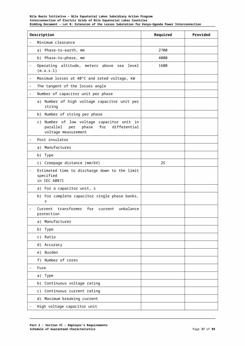
Minimum clearance
a) Phase-to-earth, mm 2700
b) Phase-to-phase, mm 4000
Operating altitude, meters above sea level (m.a.s.l) 1600
Maximum losses at 40°C and rated voltage, kW
The tangent of the losses angle
Number of capacitor unit per phase
a) Number of high voltage capacitor unit per string
Part 2 : Section VI – Employer’s RequirementsSchedule of Guaranteed Characteristics Page 30 of 75

Nile Basin Initiative – Nile Equatorial Lakes Subsidiary Action ProgramInterconnection of Electric Grids of Nile Equatorial Lakes CountriesBidding Document – Lot B: Extension of the Lessos Substation for Kenya-Uganda Power Interconnection
Description Required Provided
b) Number of string per phase
c) Number of low voltage capacitor unit in parallel per phase for differential voltage measurement
Post insulator
a) Manufacturer
b) Type
c) Creepage distance (mm/kV) 25
Estimated time to discharge down to the limit specified in IEC 60871
a) For a capacitor unit, s
b) For complete capacitor single phase banks, s
Current transformer for current unbalance protection
a) Manufacturer
b) Type
c) Ratio
d) Accuracy
e) Burden
f) Number of cores
Fuse
a) Type
b) Continuous voltage rating
c) Continuous current rating
d) Maximum breaking current
High voltage capacitor unit
a) Manufacturer
b) Type
c) Rated voltage, kV
d) Rated power, MVAr
e) Maximum power, MVAr
f) Overvoltage
1. Maximum continuous overvoltage, %
2. Maximum overvoltage for 30 minutes, %
3. Maximum overvoltage for 1 minute, %
4. Maximum overvoltage for 1 second, %
5. Maximum overvoltage for 3 cycles, %
g) Rated capacitance at 20 °C, µF
h) Capacitance manufacturing tolerance, %
i) Weight, kg
j) Bushing
1. Quantity per unit
2. Manufacturer
Part 2 : Section VI – Employer’s RequirementsSchedule of Guaranteed Characteristics Page 31 of 75
Nile Basin Initiative – Nile Equatorial Lakes Subsidiary Action ProgramInterconnection of Electric Grids of Nile Equatorial Lakes CountriesBidding Document – Lot B: Extension of the Lessos Substation for Kenya-Uganda Power Interconnection
Description Required Provided
3. Rated voltage, kV
4. Creepage distance, mm
k) Series capacitor elements
l) Parallel capacitor elements
m) Insulation embodied in each element
1. Paper and/or film
2. Type
Oil
Paper
Film
3. Thickness of film, mm
4. Design maximum dielectric stresses, kV/mm
5. Minimum rms breakdown voltage, kV
n) Container
1. Thickness of container
2. Type of material
3. Color of paint
Dimensions
a) Overall length, mm
b) Overall width, mm
c) Overall height, mm
d) Transportation dimension of heaviest part
7) Length, mm
8) Width, mm
9) Height, mm
e) Transportation dimension of largest part
7) Length, mm
8) Width, mm
9) Height, mm
f) Outline drawing No.
Part 2 : Section VI – Employer’s RequirementsSchedule of Guaranteed Characteristics Page 32 of 75

Nile Basin Initiative – Nile Equatorial Lakes Subsidiary Action ProgramInterconnection of Electric Grids of Nile Equatorial Lakes CountriesBidding Document – Lot B: Extension of the Lessos Substation for Kenya-Uganda Power Interconnection
12 kV Neutral Reactor
Description Required Provided
Manufacturer
Type
Rated voltage, kV 12
Method of cooling ONAN
Number of Phases 1
Frequency, Hz 50
Rated Temperature, °C -5 up to 40
Operating altitude, meters above sea level (m.a.s.l) 2146
Rated short circuit power, (kVA)
Permissible neutral current (A)
Power frequency withstand test voltage, (kV) 28
Test voltage
1. Short duration induced voltage test
a) High voltage winding, kV 28
2. Separate source voltages test
a) High voltage winding at 60 sec., kV 28
b) Neutral winding at 60 sec., kV
3. Impulse test voltage full wave 1.2/50 micro sec.
a) High voltage winding, kV 75
b) Neutral winding, kV 28
Zero sequence impedance (ohm/phase) Xn=Xp
Maximum ambient temperature, °C 40
Tank type Bolted type cover
Bushings
a) High voltage bushing
1) Manufacturer
2) Type
3) Rated current, A
4) Rated voltage, kV
5) Power frequency test voltage, kV >28
6) Impulse test voltage, kV >75
7) Creepage distance, mm 372
b) Low voltage bushing
1) Manufacturer
2) Type
3) Rated current, A
4) Rated voltage, kV
Part 2 : Section VI – Employer’s RequirementsSchedule of Guaranteed Characteristics Page 33 of 75
Nile Basin Initiative – Nile Equatorial Lakes Subsidiary Action ProgramInterconnection of Electric Grids of Nile Equatorial Lakes CountriesBidding Document – Lot B: Extension of the Lessos Substation for Kenya-Uganda Power Interconnection
Description Required Provided
5) Power frequency test voltage, kV
6) Impulse test voltage, kV 95
7) Creepage distance, mm
Current transformer (built-in neutral bushings)
a) Manufacturer
b) Type
c) Ratio 100/1/1A
d) Accuracy 10P20
e) Burden 15 VA
f) Number of cores 2
Accessories :
a) Type of hottest spot temperature indicator
b) Type of oil temperature indicator
c) Type of pressure relief devices
d) Type of Bucholz relay
Dimensions and weights
a) Overall length, mm
b) Overall width, mm
c) Overall height, mm
d) Total weight incl.
e) Weight of oil, (kg)
f) Weight of core and windings, (kg)
g) Shipping weight of the heaviest package, (kg)
Standards applied IEC 60076-6
Manufacturers drawing
Part 2 : Section VI – Employer’s RequirementsSchedule of Guaranteed Characteristics Page 34 of 75
Nile Basin Initiative – Nile Equatorial Lakes Subsidiary Action ProgramInterconnection of Electric Grids of Nile Equatorial Lakes CountriesBidding Document – Lot B: Extension of the Lessos Substation for Kenya-Uganda Power Interconnection
Digital Multiplex and Optical Line Termination System (SDH)
Description Required Provided
General
a) Manufacturer
b) Place of manufacture
c) Type
d) Type of multiplexer SDH: ADM
e) Complying to ITU-T rec Yes
f) Transmission Capacity (Mbits/s) STM-16: 2488
g) Access capacity on 64 kbit/s (channel) Minimum 200
h) Access capacity on 2 Mbit/s (channel) Minimum 40
i) Redundant central processor Shall be supplied
j) Digital cross connect function Fully non-blocking
k) PDH cross connect capacity Minimum 40x2Mbit/s
l) SDH cross connect capacity Minimum 4xVC4
m) Equipment used in substation environment List of 10 referencesubstation projects
n) The equipment is KEMA type tested or by equivalent independent international test center
YES
Protection functionality
a) Multiplex Section Protection MSP YES
b) Linear Trail Protection LTP YES
c) Sub Network Connection Protection SNCP YES
Teleprotection functionality:
a) Integrated distance teleprotection functionality
YES
b) Integrated optical teleprotection functionality YES
c) Addressing system for commands YES
d) Loop test for delay time YES
e) Switch-over less than 10ms YES
Available STM-1 AGGREGATES:
a) Optical SDH aggregates (ITU-T G.957) S-1.1, L-1.1,L-1.2, X-1.2
b) Based on SFP technology YES
c) Electrical SDH aggregates YES
Available USER INTERFACES
a) Voice interfaces for trunk lines:
1) 1 + 1 com path protection, available for all
YES
2) Analogue, 4wire with E&M: Input level Output level (dBr)
+7.5 to –16+7.0 to –16.5
Part 2 : Section VI – Employer’s RequirementsSchedule of Guaranteed Characteristics Page 35 of 75
Nile Basin Initiative – Nile Equatorial Lakes Subsidiary Action ProgramInterconnection of Electric Grids of Nile Equatorial Lakes CountriesBidding Document – Lot B: Extension of the Lessos Substation for Kenya-Uganda Power Interconnection
Description Required Provided
3) Analogue, 2wire with E&M: Input level Output level (dBr)
+6.5 to –12.5–1.0 to -20
4) Digital, 2Mbit/s CAS or PRI YES
b) Voice interfaces for remote subscriber:
1) 2-wire, subscriber side (dBr) -5... +4 / -7.5... -1
2) Minimal number of subscriber 10
3) 2-wire, PABX side (dBr) -5... +4 / -7.5... -3
4) Minimal number of PABX 10
Integrated tele protection
a) Interface for Commands:
1) Number of independent commands 4
2) Transmission time max. (ms) 6
3) Signal voltage (Vpeak) 250
4) 1 + 1 com path protection Yes
b) Interface(s) for Differential Protection:
c) Electrical interface: G.703 (Kbits/sec) 64
d) Optical Interface (k bits/sec) Minimum 64
Data: channels per module
a) 1 + 1 com path protection, available for all Yes
b) V.24/V.28 (RS-232): up to 38.4kbit/s Minimum 4
c) V.11/X.24 (RS-422): 64kbit/s Minimum 4
d) V.35: 64kbit/s Minimum 4
e) G.703: 64kbit/s Minimum 8
f) Ethernet: 10/100BaseT Minimum 21
g) Ethernet: WAN capacity (Mbits/sec) 63xVC12 or 3xVC3
h) Ethernet: Logical WAN ports Minimum 8
i) Ethernet: GFP (acc. ITU-T G.7041) Yes
j) Ethernet: VCAT (acc. ITU-T G.707) On VC-12 and VC-3
k) Ethernet: LCAS (acc. ITU-T G.7043) Yes
l) Ethernet: Router functionality YES
m) Ethernet: Routing protocols static IP route OSPF2 V2
n) Ethernet: WAN capacity nx64kbit/s(n=1 to 31)
o) Ethernet: WAN protocol PPP, Frame Relay(incl. RFC1490)
p) Integrated Ethernet Hub 10/100BaseT Min. 5
Integrated alarm gathering module:
a) Number of external alarms per module Min. 20
b) Auxiliary power supply for ext. contacts YES
Configuration Management
a) Type/Name of configuration tool
Part 2 : Section VI – Employer’s RequirementsSchedule of Guaranteed Characteristics Page 36 of 75
Nile Basin Initiative – Nile Equatorial Lakes Subsidiary Action ProgramInterconnection of Electric Grids of Nile Equatorial Lakes CountriesBidding Document – Lot B: Extension of the Lessos Substation for Kenya-Uganda Power Interconnection
Description Required Provided
1) For local / remote operation YES / YES
2) Data communication network (DCN) Ethernet / IP orEthernet / OSI
3) Integrated Management of Teleprotection Commands
YES
Network Management System
a) Type/Name of configuration tool
1) For fault / configuration management YES / YES
2) Data communication network (DCN) Ethernet / IP orEthernet / OSI
3) Integrated Management of Teleprotection Commands
YES
Ambient Conditions:
a) Storage: ETS 300 019-1-1, class 1.2 (°C / % hum)
-25... + 55 / class 1.2
b) Transport: ETS 300 019-1-2, class 2.2 (°C / % hum)
-25... + 70 / class 2.2
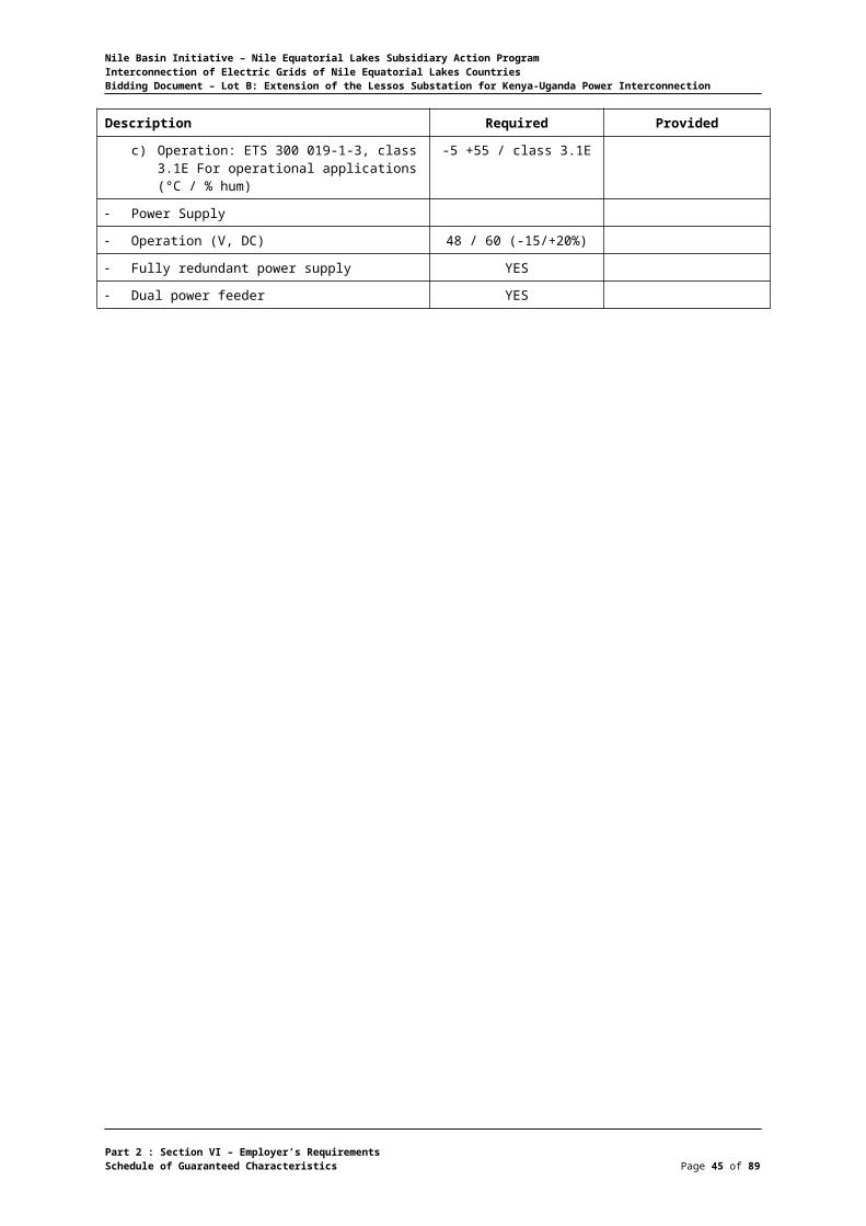
c) Operation: ETS 300 019-1-3, class 3.1E For operational applications (°C / % hum)
-5 +55 / class 3.1E
Power Supply
Operation (V, DC) 48 / 60 (-15/+20%)
Fully redundant power supply YES
Dual power feeder YES
Part 2 : Section VI – Employer’s RequirementsSchedule of Guaranteed Characteristics Page 37 of 75

Nile Basin Initiative – Nile Equatorial Lakes Subsidiary Action ProgramInterconnection of Electric Grids of Nile Equatorial Lakes CountriesBidding Document – Lot B: Extension of the Lessos Substation for Kenya-Uganda Power Interconnection
Emission of the Equipment (Substation Environment)
Description Level Comply
Test Name : Radiated radio frequency interferenceA Description : 30 MHz to 1 GHz
Basic standard: EN 55022
Test Name : Conducted radio frequency interference AC/DC Power supply A
Description : 150 kHz to 30 MHz
Basic standard: EN 55022
Immunity of the Equipment (Substation Environment)
Description Level Comply
Test Name : ESD test6 / 8kV Description : Contact/air discharge
Basic standard: IEC 61000-4-2
Test Name : Radiated electromagnetic field10 V/m Description : 80 to 1000 MHz, 80% AM, 1 kHz modulated
Basic standard: IEC 61000-4-3
Test Name : Radiated electromagnetic field10 V/m Description : 1.0 to 2.5 GHz, 80% AM, 1 kHz modulated
Basic standard: IEC 61000-4-3
Test Name : Fast transient test
a) Description :
1) AC/DC Power supply 4 kV
2) All other ports: 2 kV
b) Basic standard: IEC 61000-4-4
Test Name : Surge test (1.2/50 ms)
a) Description :
1) AC/DC Power supply:
Common mode 2.0 kV
Differential mode 1.0 kV
2) DC Power supply 48 V:
Common mode 0.5 kV
Differential mode 0.5 kV
3) Signal terminals
Common mode 2.0 kV
Differential mode 1.0 kV
4) Telecommunication ports:
Common mode 1.5 kV
Part 2 : Section VI – Employer’s RequirementsSchedule of Guaranteed Characteristics Page 38 of 75
Nile Basin Initiative – Nile Equatorial Lakes Subsidiary Action ProgramInterconnection of Electric Grids of Nile Equatorial Lakes CountriesBidding Document – Lot B: Extension of the Lessos Substation for Kenya-Uganda Power Interconnection
Description Level Comply
b) Basic standard: IEC 61000-4-5
Test Name : Conducted radio frequency interference10 V (e.m.f.)a) Description : 0.15 to 80 MHz, 80% AM, 1 kHz
modulated
b) Basic standard: IEC 61000-4-6
Test Name : Power frequency magnetic field
a) Description :
1) Continuous 30 A/m
2) Short (1 to 3 s) 300 A/m
b) Basic standard: IEC 61000-4-8
Test Name : Damped oscillatory waves
a) Description :
1) AC/DC Power supply:
Common mode 2.5 kV
Differential mode 1.25 kV
2) Signal terminals:
Common mode 2.5 kV
Differential mode 1.25 kV
3) Telecommunication ports:
Common mode 1 MHz, 400 Hz repetition rate, 2 s burst duration
2.5 kV
b) Basic standard: IEC 61000-4-12
Test Name : Conducted common mode disturbance 10 / 30 Vrms
a) Description : Frequency 50 Hz, continuous mode
b) Basic standard: IEC 61000-4-16
Note: - The filled guaranteed data for SDH should be proven by attaching the catalogue of the proposed type of SDH
Part 2 : Section VI – Employer’s RequirementsSchedule of Guaranteed Characteristics Page 39 of 75

Nile Basin Initiative – Nile Equatorial Lakes Subsidiary Action ProgramInterconnection of Electric Grids of Nile Equatorial Lakes CountriesBidding Document – Lot B: Extension of the Lessos Substation for Kenya-Uganda Power Interconnection
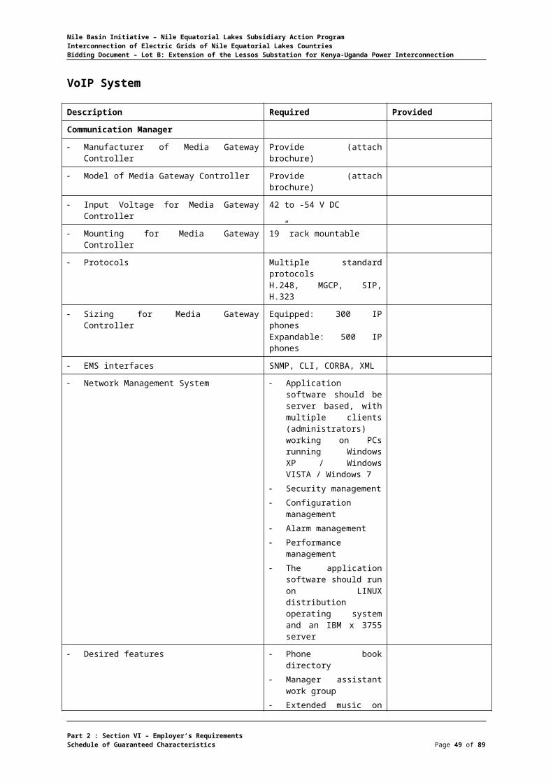
VoIP System
Description Required Provided
Communication Manager
Manufacturer of Media Gateway Controller Provide (attach brochure)
Model of Media Gateway Controller Provide (attach brochure)
Input Voltage for Media Gateway Controller 42 to -54 V DC
Mounting for Media Gateway Controller 19” rack mountable
Protocols Multiple standard protocolsH.248, MGCP, SIP, H.323
Sizing for Media Gateway Controller Equipped: 300 IP phonesExpandable: 500 IP phones
EMS interfaces SNMP, CLI, CORBA, XML
Network Management System Application software should be server based, with multiple clients (administrators) working on PCs running Windows XP / Windows VISTA / Windows 7
Security management Configuration
management Alarm management Performance
management The application software
should run on LINUX distribution operating system and an IBM x 3755 server
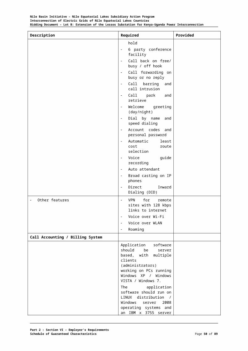
Desired features Phone book directory Manager assistant work
group Extended music on hold 6 party conference facility Call back on free/ busy /
off hook Call forwarding on busy
or no reply Call barring and call
intrusion Call park and retrieve Welcome greeting
(day/night) Dial by name and speed
dialing Account codes and
personal password Automatic least cost
route selection Voice guide recording Auto attendant Broad casting on IP
Part 2 : Section VI – Employer’s RequirementsSchedule of Guaranteed Characteristics Page 40 of 75

Nile Basin Initiative – Nile Equatorial Lakes Subsidiary Action ProgramInterconnection of Electric Grids of Nile Equatorial Lakes CountriesBidding Document – Lot B: Extension of the Lessos Substation for Kenya-Uganda Power Interconnection
Description Required Provided
phones Direct Inward Dialing
(DID)
Other features VPN for remote sites with 128 kbps links to internet
Voice over Wi-Fi Voice over WLAN Roaming
Call Accounting / Billing System
Application software should be server based, with multiple clients (administrators) working on PCs running Windows XP / Windows VISTA / Windows 7.The application software should run on LINUX distribution / Windows server 2008 operating systems and an IBM x 3755 server should support 300 IP phone users
Trunk Gateway
Analogue Interfaces ports 16 no. 2 wire FXO48 no. 2 wire FXS10 no. 4 wire (E&M) with CAS & R2 signaling
Digital interface ports 10 no. ISDN PRI1 no. ISDN BRI8 no. E1
Protocols H.323, SIP, ISDN PRI, SS7, etc.
Voice CODECS G.711, G.729a/b, G.723.1, G.726
Input Power -42 to -54Vdc
IP Standard Phones
Integral switch 10/100
Speaker phone Full duplex with echo cancellation
Line keys 6
Programmable soft keys 4 (+2 speed dial/line)
Fixed feature keys 8
Message waiting Blinking indication
Ethernet ports Minimum 2
Display Graphical TFT color display
XML support Yes
Signaling protocol SIP
PoE power classification Class 2
Configuration Both static and DHCP support
PoE switches
Part 2 : Section VI – Employer’s RequirementsSchedule of Guaranteed Characteristics Page 41 of 75

Nile Basin Initiative – Nile Equatorial Lakes Subsidiary Action ProgramInterconnection of Electric Grids of Nile Equatorial Lakes CountriesBidding Document – Lot B: Extension of the Lessos Substation for Kenya-Uganda Power Interconnection
Description Required Provided
Port 24 and 48
Cabling type UTP
LED PWR, Fan
Power On Ethernet port
In put power
Performance Switching capacity
Forwarding capacity
Number of VLANs
VLAN Protocol
IPv6
Management Web user interface
SNMP
SNMP MIBs
Remote Monitoring (RMON)
Firmware upgrade
Port mirroring
Other management
Security IEEE 802.1X
ACLs
Availability Link aggregation
Storm control
Spanning Tree
DoS prevention
IGMP (version 1 and 2) snooping.
Power redundancy
Quality of service Priority levels
Scheduling
Class of service
Rate limiting
Statistics
Standards
Part 2 : Section VI – Employer’s RequirementsSchedule of Guaranteed Characteristics Page 42 of 75

Nile Basin Initiative – Nile Equatorial Lakes Subsidiary Action ProgramInterconnection of Electric Grids of Nile Equatorial Lakes CountriesBidding Document – Lot B: Extension of the Lessos Substation for Kenya-Uganda Power Interconnection
Digital Control and Monitoring System
Description Required Provided
Manufacturer Required
Place of manufacture Required
System designation Required
Software Required
a) Software designation Required
b) Literature reference principle of operation Required
c) Provide software function and capability Required
Literature for principle of operation Required
Power supply voltage, V 230 AC +25%
Expandability 100%
Availability >99.99%
Mean time to repair, H <2hrs or better
Mean time between failure, H >36000hrs or better
Local LCD display Required
Operating temperature range, °C 0-50
Equipment enclosures
a) Degree of protection IP55
b) Mounting (Flush, surface, rack) Flush
System function
a) Monitoring function required:
1) Switching status (circuit breaker, Disconnectors etc.)
Required
2) Indication and alarm status Required
3) Analogue measurements (currents, voltages, etc.)
Required
b) Resolution of time tagging 1 ms
Trend reports: Day (mean, peak) Month (mean, peak) Semi-annual (mean, peak) Year (mean, peak)Historical reports: Day Week Month Year
Required
c) Control function required:
1) Close/open of circuit breakers , Isolators, etc
Required
2) Close/open disconnectors , Earth switches
Required
Part 2 : Section VI – Employer’s RequirementsSchedule of Guaranteed Characteristics Page 43 of 75

Nile Basin Initiative – Nile Equatorial Lakes Subsidiary Action ProgramInterconnection of Electric Grids of Nile Equatorial Lakes CountriesBidding Document – Lot B: Extension of the Lessos Substation for Kenya-Uganda Power Interconnection
Description Required Provided
3) Transformer automatic tap changer control
Required
4) Bay interlocking facilities Required
d) Reporting function required:
1) Sequence of events recording Required
2) Post-mortem review Required
3) Fault waveform capture Required
4) Tenderer to state capacity and functionality
Communication
a) Number of communication channels At least two
b) Number and type of communication ports As required + 2 spares
c) Communication protocol required:
1) IEC 61850 Required Required
2) List of protocols Supported by the System Required
3) List of manufacturers the System has interfaced
Required
Part 2 : Section VI – Employer’s RequirementsSchedule of Guaranteed Characteristics Page 44 of 75
Nile Basin Initiative – Nile Equatorial Lakes Subsidiary Action ProgramInterconnection of Electric Grids of Nile Equatorial Lakes CountriesBidding Document – Lot B: Extension of the Lessos Substation for Kenya-Uganda Power Interconnection
Bay Control Unit
Description Required Provided
Manufacturer
Place of manufacture
Literature for principle of operation
Power supply voltage, V 110 DC +/-25%
Power requirements, W ≤ 5
Maximum number of expansion module < 2
Mean time to repair, H
Mean time between failure, H >40,000
Local LCD display Required
Operating temperature range, °C 0-50
BCU enclosure
a) Degree of protection IP 54
b) Mounting (Flush, surface, rack) Flush
BCU function
a) Monitoring function required:-
1) Switching status (circuit breaker, etc.) Required
2) Indication and alarm status Required
3) Analogue measurements (currents, voltages, etc.)
Required
b) Resolution of time tagging 1 ms
c) Control function required:
1) Close/open of circuit breakers Required
2) Close/open disconnectors Required
3) Transformer automatic tap changer control Required
4) Synchronization check control Required
5) Bay interlocking facilities Required
d) Reporting function required:
1) Sequence of events recording Required
2) Post-mortem review Required
3) Fault waveform capture Required
4) Tenderer to state capacity and functionality
Communication
a) Number of communication channels ≥ 4
b) Number and type of communication ports
c) Communication protocol required:-
1) IEC 61850 Required
2) List of protocols available at BCU Yes
3) List of manufacturers the BCU has interfaced Yes
Part 2 : Section VI – Employer’s RequirementsSchedule of Guaranteed Characteristics Page 45 of 75

Nile Basin Initiative – Nile Equatorial Lakes Subsidiary Action ProgramInterconnection of Electric Grids of Nile Equatorial Lakes CountriesBidding Document – Lot B: Extension of the Lessos Substation for Kenya-Uganda Power Interconnection
Description Required Provided
Digital input module
a) Module designation
b) Literature reference principle of operation Yes
c) Maximum number of modules per BCU Required
d) Maximum number of inputs per module
e) Input voltage, V DC
f) Configuration of input required:-
1) Status and alarms Required
2) Sequence of events Required
3) BCD or parallel inputs Required
4) Pulse accumulator Required
a) Standard number of inputs per module
b) Type of input circuit isolation
c) Scan time, ms
d) Minimum pulse duration, ms
e) Input impedance, ohm
Digital output module
a) Module designation
b) Literature reference principle of operation
c) Maximum number of modules per BCU
d) Maximum number of outputs per module
e) Maximum output current, A
f) Maximum switched output voltage, V
g) Type of protection against back EMF
Analogue input module
a) Module designation
b) Literature reference principle of operation
c) Maximum number of modules per BCU
d) Maximum number of inputs per module
e) Resolution, bits
f) Accuracy, %
g) Common mode noise rejection, dB
h) Normal mode noise rejection, dB
i) Conversion time, ms
j) Scanning time (per channel), ms
k) Input signal types (e.g. 4-20 mA)
Analogue output module
a) Module designation
b) Literature reference principle of operation
c) Maximum number of modules per BCU
Part 2 : Section VI – Employer’s RequirementsSchedule of Guaranteed Characteristics Page 46 of 75

Nile Basin Initiative – Nile Equatorial Lakes Subsidiary Action ProgramInterconnection of Electric Grids of Nile Equatorial Lakes CountriesBidding Document – Lot B: Extension of the Lessos Substation for Kenya-Uganda Power Interconnection
Description Required Provided
d) Maximum number of inputs per module
e) Output voltage range, V
f) Output current range, mA
g) Type of isolation
h) Load resistance, ohm
i) Conversion time
j) Accuracy, %
Direct AC connection voltage
a) Module designation
b) Literature reference principle of operation
c) Maximum number of modules per BCU
d) Maximum number of inputs per module
e) Input voltage range, V AC
f) Burden on instrument transformer circuit, VA
g) Conversion time, ms
h) Scanning resolution, bits
i) Accuracy, %
j) What calculations are supported?
k) Method of isolation
Direct AC connection current
a) Module designation
b) Literature reference principle of operation
c) Maximum number of modules per BCU
d) Maximum number of inputs per module
e) Input current range, A AC
f) Burden on instrument transformer circuit, VA
g) Conversion time, ms
h) Scanning resolution, bits
i) Accuracy, %
j) What calculations are supported?
k) Method of isolation
Software
a) Software designation
b) Literature reference principle of operation
c) Provide software function and capability
d) Maximum number of inputs per module
Part 2 : Section VI – Employer’s RequirementsSchedule of Guaranteed Characteristics Page 47 of 75
Nile Basin Initiative – Nile Equatorial Lakes Subsidiary Action ProgramInterconnection of Electric Grids of Nile Equatorial Lakes CountriesBidding Document – Lot B: Extension of the Lessos Substation for Kenya-Uganda Power Interconnection
Tele Protection Equipment
Description Required Provided
Manufacturer
Place of manufacture
Type
DC Voltage supply range
Communication Interfaces (types, number)
Number of command (channel) 4
Number of maximum Input/output cards
Time synchronization 1 ms
Transmit time
Receiver response time for :
a) Blocking < 10 ms
b) Permissive < 14 ms
c) Direct tripping
Dimension (mm)
Power supply (V, DC) 48
Standard applied IEC 60834-1
Part 2 : Section VI – Employer’s RequirementsSchedule of Guaranteed Characteristics Page 48 of 75
Nile Basin Initiative – Nile Equatorial Lakes Subsidiary Action ProgramInterconnection of Electric Grids of Nile Equatorial Lakes CountriesBidding Document – Lot B: Extension of the Lessos Substation for Kenya-Uganda Power Interconnection
Line Differential Relay, Protection "A"
Description Required Provided
Manufacturer
Place of manufacture
Relay type
Type of line differential protection Segregated phase
Rated current (A) 1 and 5
Rated voltage (V) 110
Number of Phases 3
Rated frequency, (Hz) 50
Measuring characteristics of distance elements (quadrilateral, Mho,___
Quadrilateral &Mho
Range of auxiliary DC supply (Volts) 110 + 20%
Relay operating time (msec.) ≤ 35
Quantity of output relays or contacts
Quantity of LEDs for indication ≥ 7 user programmable
Time synchronization signal IRIG-B
Time tagging resolution (msec.) ± 1
Front serial interface communication:
a) Baud rate
b) Connection RS 232
System interface:
a) Connection RS 485
b) Protocol IEC 61850
c) Communication speed
Remote change of active group allowed (Yes / No) Yes
Remote change of settings allowed (Yes / No) Yes
Distance protection zones (Number of zones) ≤ 25
Distance element
a) Typical operating time (ms)
b) Minimum operating current (Phase current)
c) Resetting ratio (%)
d) Time setting range for impedance zones (Sec)
e) Time setting step increment (Sec)
f) Line angle setting range (degree)
g) Line angle setting step increment (degree)
h) Impedance setting for quadrilateral characteristics:
1) Reactive reach
Positive sequence reactance setting range (ohm)
Part 2 : Section VI – Employer’s RequirementsSchedule of Guaranteed Characteristics Page 49 of 75
Nile Basin Initiative – Nile Equatorial Lakes Subsidiary Action ProgramInterconnection of Electric Grids of Nile Equatorial Lakes CountriesBidding Document – Lot B: Extension of the Lessos Substation for Kenya-Uganda Power Interconnection
Description Required Provided
Positive sequence reactance step increment (ohm)
Zero sequence reactance setting range (ohm)
Zero sequence reactance step increment (ohm)
2) Resistive reach
Positive sequence reactance setting range (ohm)
Positive sequence reactance step increment (ohm)
Zero sequence reactance setting range (ohm)
Zero sequence reactance step increment (ohm)
3) Fault resistance
setting range for phase to phase faults (ohm)
setting range for phase to earth faults (ohm)
Step increment for phase to phase faults (ohm)
Step increment for phase to earth faults (ohm)
High set overcurrent protection:
a) Definite time overcurrent phase current setting range (A)
b) Definite time overcurrent time setting range (Sec)
c) Dropout ratio
d) Inverse time overcurrent phase current starting (A)
e) Inverse time overcurrent time multiplier range
Low set overcurrent protection: -
a) Definite time overcurrent phase current setting range (A)
b) Definite time overcurrent time setting range (Sec)
c) Dropout ratio
d) Inverse time overcurrent phase current starting (A)
e) Inverse time overcurrent time multiplier range
High set earth fault protection:
a) Definite time overcurrent earth fault setting range (A)
b) Definite time overcurrent time delay
Part 2 : Section VI – Employer’s RequirementsSchedule of Guaranteed Characteristics Page 50 of 75

Nile Basin Initiative – Nile Equatorial Lakes Subsidiary Action ProgramInterconnection of Electric Grids of Nile Equatorial Lakes CountriesBidding Document – Lot B: Extension of the Lessos Substation for Kenya-Uganda Power Interconnection
Description Required Provided
setting range (Sec)
c) Inverse time overcurrent earth fault starting (A)
d) Inverse time overcurrent time multiplier range
Low set earth fault protection:
a) Definite time overcurrent earth fault setting range (A)
b) Inverse time overcurrent earth fault starting (A)
c) Inverse time overcurrent time multiplier range
Direction detection for phase overcurrent:
a) Forward range – Inductive angle (degree)
b) Forward range – Resistive angle (degree)
c) Forward range – Capacitive angle (degree)
Direction detection for earth faults: -
a) Forward range – Inductive angle (degree)
b) Forward range – Resistive angle (degree)
c) Forward range – Capacitive angle (degree)
Autoreclosure:- Required
a) Number of reclosures
b) Dead time range (sec)
c) Reclaim time range (sec)
d) Operating mode with check synchronizing function
Breaker failure protection current setting range (A)
Breaker failure protection time setting range (Sec)
Sensitive earth fault protection function included (Yes / No)
Not Required
Negative sequence current detection function included (Yes / No)
Not Required
Phase discontinuity / broken conductor detection function included
Yes
Under voltage protection setting range: Not Required
a) For phase to phase connection (Volts)
b) For phase to earth connection (Volts)
Over voltage protection setting range: - Not Required
a) For phase to phase connection (Volts)
b) For phase to earth connection
Part 2 : Section VI – Employer’s RequirementsSchedule of Guaranteed Characteristics Page 51 of 75
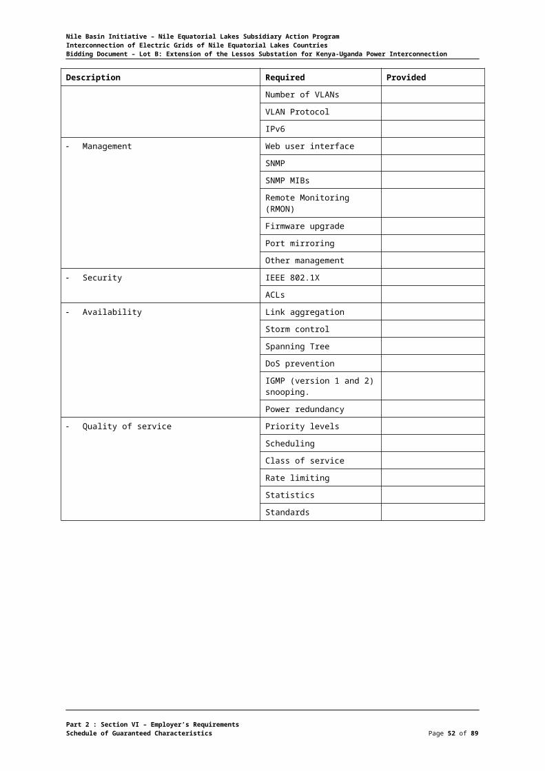
Nile Basin Initiative – Nile Equatorial Lakes Subsidiary Action ProgramInterconnection of Electric Grids of Nile Equatorial Lakes CountriesBidding Document – Lot B: Extension of the Lessos Substation for Kenya-Uganda Power Interconnection
Description Required Provided
Frequency protection;- Not Required
a) Number of frequency element / stage
b) Setting range (Hz)
c) Time delay setting (Sec)
Fault locator output for fault distance indication (in ohm, km, %)
ohm ; km ; %
Measured values ranges and display, please list: -
Metering:
a) Forward kWh range Yes
b) Reverse kWh range Yes
c) Forward kVarh range Yes
d) Reverse kVarh range Yes
Synchrocheck function included (Yes / No) Yes
Disturbance recording setting: -
a) Pre-fault time range (msec)
b) Post-fault time range (msec)
Part 2 : Section VI – Employer’s RequirementsSchedule of Guaranteed Characteristics Page 52 of 75

Nile Basin Initiative – Nile Equatorial Lakes Subsidiary Action ProgramInterconnection of Electric Grids of Nile Equatorial Lakes CountriesBidding Document – Lot B: Extension of the Lessos Substation for Kenya-Uganda Power Interconnection
Distance Relay, Protection "B"
Description Required Provided
Manufacturer
Place of manufacture
Relay type
Rated current (A) 1 and 5
Rated voltage 110
Number of Phases 3
Rated frequency (Hz) and frequency operating range 50 Hz & 45-55 Hz
Measuring characteristic (Quadrilateral, Mho, Elliptical) Quadrilateral & Mho
Burden in the CT circuits with 1A (VA)
Burden in the CT circuits with 5A (VA)
Burden in the VT circuits, (VA)
Range of auxiliary DC supply (Volts) 110+ 20%
Quantity of output relays or contacts ≥9 N/O ; ≥ 9 N/C
Quantity of LEDs for indications ≥ 7 userprogrammable
Time synchronization signal IRIG-B
Time tagging resolution (msec) ±1
Front serial interface communication:
a) Baud rate
b) Connection RS 232
System interface: -
a) Connection RS 485
b) Protocol IEC 61850
c) Communication speed
Remote change of active group allowed (Yes / No) yes
Remote change of settings allowed (Yes / No) yes
Distance protection zones (Number of zones) ≥ 5
Typical operating time (ms) ≤ 25
Minimum operating current (Phase current)
Resetting ratio (%)
Time setting range for impedance zones (Sec)
Time setting step increment (Sec)
Line angle setting range (degree)
Line angle setting step increment (degree)
Impedance setting for quadrilateral characteristics:
a) Reactive reach
1) Positive sequence reactance setting range (Ohm)
Part 2 : Section VI – Employer’s RequirementsSchedule of Guaranteed Characteristics Page 53 of 75
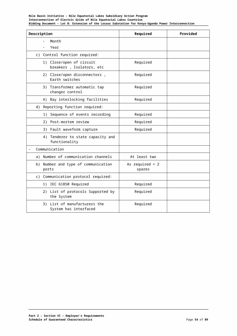
Nile Basin Initiative – Nile Equatorial Lakes Subsidiary Action ProgramInterconnection of Electric Grids of Nile Equatorial Lakes CountriesBidding Document – Lot B: Extension of the Lessos Substation for Kenya-Uganda Power Interconnection
Description Required Provided
2) Positive sequence reactance step increment (Ohm)
3) Zero sequence reactance setting range (Ohm)
4) Zero sequence reactance step increment (Ohm)
b) Resistive reach
1) Positive sequence resistance setting range (Ohm)
2) Positive sequence resistance step increment (Ohm)
3) Zero sequence resistance setting range (Ohm)
4) Zero sequence resistance step increment (Ohm)
c) Fault resistance
1) Setting range for phase to phase faults (Ohm)
2) Setting range for phase to earth faults (Ohm)
3) Step increment for phase to phase faults setting (Ohm)
4) Step increment for phase to earth faults setting (Ohm)
Type of starting:
a) Overcurrent Yes
b) Earth fault Yes
c) Under voltage Yes
d) Under impedance Yes
Earth fault pick-up neutral current (3Io) setting range for 1A
Earth fault pick-up neutral current (3Io) setting range for 5A
Zero sequence compensation factor (Ko) setting range
Zero sequence compensation factor angle ϕKo setting range
Fault locator output (in ohm, km, etc) ohm, km, %
Power swing detection:-
a) Mode of operation
b) Power swing blocking programs
Tripping and reclosing mode 1 phase & 3 phase
Directional earth fault protection:
a) Characteristics (Definite time or inverse time)
b) Current setting range for definite time
c) Time setting range for definite time
d) Time multiplier setting range for inverse characteristics
e) Available characteristic for inverse time
f) Minimum setting range for zero-sequence voltage (3Vo)
Weak in feed protection:
a) Operation mode
b) Setting range of under voltage phase to ground
c) Time setting range
Backup over current protection
Part 2 : Section VI – Employer’s RequirementsSchedule of Guaranteed Characteristics Page 54 of 75

Nile Basin Initiative – Nile Equatorial Lakes Subsidiary Action ProgramInterconnection of Electric Grids of Nile Equatorial Lakes CountriesBidding Document – Lot B: Extension of the Lessos Substation for Kenya-Uganda Power Interconnection
Description Required Provided
a) Available characteristics
b) Current setting range for definite time
c) Time setting range for definite time
d) Current setting range for inverse characteristics
e) Earth fault current setting range for definite time
f) Earth fault time setting range for definite time
g) Earth fault current setting range for inverse time
h) Time multiplier setting range for inverse time
i) Available characteristics for inverse time
Switch-on-to fault protection:
a) Operating mode
b) Range of pick-up current
Breaker failure protection:-
a) Setting range of pick-up current
b) Setting range of time delay
Auto reclosure:
a) Operating mode single pole and three poles
b) Operating mode with check synchronizing function
c) Setting range for dead time
d) Setting range for reclaim time
Operational measured values:
a) Please list all the measured and displayed parameters
Over voltage protection:- Required
a) Setting range for phase to ground over voltage
b) Setting range for zero sequence over voltage (3Vo)
c) Setting range for phase to phase over voltage
Under voltage protection: Required
a) Setting range for phase to ground under voltage
b) Setting range for phase to phase under voltage
c) Setting range for phase to phase under voltage
Part 2 : Section VI – Employer’s RequirementsSchedule of Guaranteed Characteristics Page 55 of 75
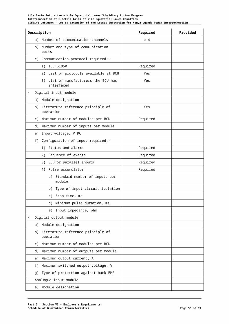
Nile Basin Initiative – Nile Equatorial Lakes Subsidiary Action ProgramInterconnection of Electric Grids of Nile Equatorial Lakes CountriesBidding Document – Lot B: Extension of the Lessos Substation for Kenya-Uganda Power Interconnection
Transformer Protection
Description Required Provided
Manufacturer
Place of manufacture
Relay type
Rated frequency, (Hz) 50
Rated voltage, DC (Volts) 110
Number of Phases 3
Rated current HV side (A) 1 and 5
Rated current LV side (A) 1 and 5
Rated current tertiary side (A) 1 and 5
Range of auxiliary DC supply (Volts) 110 ± 20%
Number of output relays or contacts
Number of LEDs for indications ≥ 4 user programmable
System interface:
a) Connection RS 485
b) Protocol IEC 61850
c) Communication speed ≥ 9600 kb/s
Front serial interface communication:
a) Baud rate
b) Connection RS 232
Service / modem interface connection RS 232, RS 485 or fiber optic)
RS 485
Time synchronization signal IRIG-B
Time tagging resolution (msec) ± 1
Nominal relay operating time (msec) ≤ 35
Differential protection settings: -
a) Pick-up values range of differential current
b) High current stage range
c) Inrush restraint ratio (2nd harmonic)
d) Stabilization ratio further (n – th) harmonic
e) Dropout ratio
Built in CT ratio and vector group matching included (yes / no)
Yes
Transformer star point conditioning (earthed, non – earthed) earthed
Restricted earth fault protection setting:
a) Differential current setting range
b) Time delay setting range
Definite time three phase over current and earth fault protection setting: -
Part 2 : Section VI – Employer’s RequirementsSchedule of Guaranteed Characteristics Page 56 of 75

Nile Basin Initiative – Nile Equatorial Lakes Subsidiary Action ProgramInterconnection of Electric Grids of Nile Equatorial Lakes CountriesBidding Document – Lot B: Extension of the Lessos Substation for Kenya-Uganda Power Interconnection
Description Required Provided
a) High set phase current setting (A)
b) High set earth fault setting (A)
c) Low set phase current setting (A)
d) Low set earth fault current setting (A)
e) Time setting range for high set phase current setting (sec)
f) Time setting range for low set phase current setting (sec)
g) Time setting range for high set earth fault setting (sec)
h) Time setting range for low set earth fault setting (sec)
Inverse time three phase over current and earth fault protection setting: -
a) Phase starting current setting range
b) Time setting range for phase current
c) Earth fault starting current setting range
d) Time setting range for earth fault current
Breaker failure protection time setting range (sec)
Breaker failure protection current setting range (A)
Number of stored last faults ≥ 5
Measured operational values:
a) Measured phase current range
b) Measured unbalanced current range
c) Measured differential current range
d) Measured restricted earth fault current range
Part 2 : Section VI – Employer’s RequirementsSchedule of Guaranteed Characteristics Page 57 of 75

Nile Basin Initiative – Nile Equatorial Lakes Subsidiary Action ProgramInterconnection of Electric Grids of Nile Equatorial Lakes CountriesBidding Document – Lot B: Extension of the Lessos Substation for Kenya-Uganda Power Interconnection
Bus Bar Differential Protection
Description Required Provided
Manufacturer
Place of manufacture
Relay type
Rated current (A) 1 and 5
Number of Phases 3
Rated frequency (Hz) 50
Rated of auxiliary supply range (Volts, DC) 110 + 20%
Number of LEDs for indication ≥ 10
System interface: -
a) Connection RS 485
b) Protocol IEC 61850
c) Communication speed ≥ 9600 kb/s
Front serial interface communication:
a) Baud rate
b) Connection RS 232
Service / modem interface connection (RS 232, RS 485 or fiber optic)
RS 485
Time synchronization signal IRIG-B
Time tagging resolution (msec) ± 1
Bus bar protection:
a) Over current setting range
b) Stabilizing factor setting range for bus bar
c) Selective protection Yes
d) Stabilizing factor K for check zone
Typical tripping time (msec) ≤ 20
Differential current monitoring setting range
Breaker failure protection current setting range
Breaker failure protection time setting range
Isolator transition time setting range
Over current protection in the bay unit
a) Definite time characteristics:
1) High set over-current current setting range
2) High set over-current time setting range
3) Low set over-current current setting range
4) Low set over-current time setting range
5) High set earth fault current setting range
6) High set earth fault time setting range
7) Low set earth fault current setting range
Part 2 : Section VI – Employer’s RequirementsSchedule of Guaranteed Characteristics Page 58 of 75

Nile Basin Initiative – Nile Equatorial Lakes Subsidiary Action ProgramInterconnection of Electric Grids of Nile Equatorial Lakes CountriesBidding Document – Lot B: Extension of the Lessos Substation for Kenya-Uganda Power Interconnection
Description Required Provided
8) Low set earth fault time setting range
b) Inverse time over current characteristics:
1) Phase over current setting range
2) Earth fault setting range
3) Time delay for phase over current
4) Time delay for earth fault
Setting range for over current release of trip command
Operational measured values of central unit Id & Ibias
Operational measured values of bay units I Phase, Io, frequency
Number of events recorded in the central units ≥ 10
Number of events recorded in the bay units ≥ 256
Number of faults recorded in the central unit ≥ 5
Number of faults recorded in the bay units ≥ 5
Number of equipped bays
Part 2 : Section VI – Employer’s RequirementsSchedule of Guaranteed Characteristics Page 59 of 75

Nile Basin Initiative – Nile Equatorial Lakes Subsidiary Action ProgramInterconnection of Electric Grids of Nile Equatorial Lakes CountriesBidding Document – Lot B: Extension of the Lessos Substation for Kenya-Uganda Power Interconnection
Energy Meter
Description Required Provided
Manufacturer
Place of manufacture
Type of energy meter
Rated input voltage (V) 100
Rated input current (Amps) 1 and 5
Type of auxiliary power supply (DC voltage, or self powered) 110 V, DC
Accuracy class
a) For active energy (IEC 61036)
b) For reactive energy (IEC 61268) ≤ 2
Short time maximum current rating (A)
Minimum starting current required (A) < 0.01 x In
Voltage ratings:
a) 3 phase 4 wire, 3-element phase to neutral voltage, single phase connection
b) 3 phase 3 wire, 2-element phase to phase voltage, single phase connection
Over load current setting (A) ≥ 200% x In
Programmable CT and VT ratio facility included (Yes/No) Yes
Present demand and demand since last reset are available or displayed (Yes/No)
Yes
Maximum demand indication period, minutes ≥ 60
Demand values for current, active power, reactive power and apparent power included (Yes/No)
Yes
Backup power type (please specify if available)
Battery type (If used)
Battery life time (If battery is used)
Communication type available for remote communication with SCADA or national control center
RS 485
Communication baud rate ≥ 9600
Display size
Display maximum digit
Number of parameters simultaneously displayed ≥ 3
Please list all the measurements, calculations and displayed parameters available
Size
Weight
Part 2 : Section VI – Employer’s RequirementsSchedule of Guaranteed Characteristics Page 60 of 75

Nile Basin Initiative – Nile Equatorial Lakes Subsidiary Action ProgramInterconnection of Electric Grids of Nile Equatorial Lakes CountriesBidding Document – Lot B: Extension of the Lessos Substation for Kenya-Uganda Power Interconnection
Batteries and Dual Charger
Description Required Provided
BATTERY 110 V, DC
a) Manufacturer
b) Type, Nickel–Cadmium(Ni-Cd)
c) Voltage per cell, D.C. (V) 1.2
d) Capacity at 10-hr discharge rate (AH) ≥ 220
e) Number of cells 96 (92+4 spare)
f) Dimensions of each cell, (mm)
g) Weight (kg)
h) Standard applied IEC 60623
BATTERY 48 V, DC
a) Manufacturer
b) Type Nickel–Cadmium(Ni-Cd)
c) Voltage per cell, D.C. (V) 1.2
d) Capacity at 10-hr discharge rate (AH) ≥ 220
e) Number of cells 42 (40+2 spare)
f) Dimensions of each cell, (mm)
g) Weight (kg)
h) Standard applied IEC 60623
DUAL CHARGER FOR 110 V, DC BATTERY
a) Manufacturer
b) Type Thyristor Controlled
c) Type of cooling Self-ventilating
d) Protection class of cubicle IP 41
e) Output (V, DC) 110
DUAL CHARGER FOR 48 V, DC BATTERY
a) Manufacturer
b) Type Thyristor Controlled
c) Type of cooling Self-ventilating
d) Protection class of cubicle IP 41
e) Output (V, DC) 48
f) Dimensions (mm)
A.C. Distribution Panel
Description Required Provided
Manufacturer
Place of manufacture
Part 2 : Section VI – Employer’s RequirementsSchedule of Guaranteed Characteristics Page 61 of 75

Nile Basin Initiative – Nile Equatorial Lakes Subsidiary Action ProgramInterconnection of Electric Grids of Nile Equatorial Lakes CountriesBidding Document – Lot B: Extension of the Lessos Substation for Kenya-Uganda Power Interconnection
Type
Rated voltage (V) 415
Rated current of main bus bar (A) ≥ 630
Cross-section of bus bar (sq.mm)
Permissible short circuit current (kA) ≥ 25
Thickness of sheet steel, (mm)
Applied test voltage, 50Hz 1 min (kV) 2,5
Dimensions
a) Length, (mm) ≤ 1000
b) Width, (mm) ≤ 600
c) Height, (mm) ≤ 2250
d) Weight (kg)
Manufacturers catalogues designation of A.C. panel and low voltage equipment
Standards applied IEC or equiv.
Part 2 : Section VI – Employer’s RequirementsSchedule of Guaranteed Characteristics Page 62 of 75

Nile Basin Initiative – Nile Equatorial Lakes Subsidiary Action ProgramInterconnection of Electric Grids of Nile Equatorial Lakes CountriesBidding Document – Lot B: Extension of the Lessos Substation for Kenya-Uganda Power Interconnection
D.C Distribution Panel
Description Required Provided
Manufacturer
Type
Place of manufacture
Rated voltage (V) 110, V, DC
Cross-section of bus bar (sq.mm)
Thickness of sheet steel, (mm) 2,5
Permissible short circuit current (kA) ≥ 6
Applied test voltage, 50Hz 1 min (kV)
Dimensions
a) Length, (mm) ≤ 1000
b) Width, (mm) ≤ 600
c) Height, (mm) ≤ 2250
d) Weight (kg)
Manufacturers catalogues designation of D.C. panel and low voltage equipment
Standards applied IEC or equiv.
Part 2 : Section VI – Employer’s RequirementsSchedule of Guaranteed Characteristics Page 63 of 75

Nile Basin Initiative – Nile Equatorial Lakes Subsidiary Action ProgramInterconnection of Electric Grids of Nile Equatorial Lakes CountriesBidding Document – Lot B: Extension of the Lessos Substation for Kenya-Uganda Power Interconnection
Control, Protection, Signaling and Meter Panel
Description Required Provided
Control Panels
a) Manufacturer
b) Place of manufacturer
c) Type
d) Equipment arrangement
e) Thickness of sheet steel, (mm) ≥ 2
f) Painting
g) Transducer auxiliary supply (AC, DC or self powered, etc.)
110 VDC or 48 VDC
h) Dimensions
i) Length, (mm) ≤ 1000
j) Width, (mm) ≤ 600
k) Height, (mm) ≤ 2250
l) Maximum shipping weight, (kg)
Protection Panels
a) Manufacturer
b) Place of manufacturer
c) Type
d) Front door with translucent window type (Yes/No) Yes
e) Equipment mounted on racks (Yes/No) Yes
f) Thickness of sheet steel, (mm) ≥ 2
g) Dimensions
h) Length, (mm) ≤ 1000
i) Width, (mm) ≤ 600
j) Height, (mm) ≤ 2250
k) Maximum shipping weight, (kg)
l) Standard applied IEC or equiv.
SCADA interface panels
a) Manufacturer
b) Place of manufacturer
c) Type
d) Painting
e) Transducer auxiliary supply (AC, DC or self powered, etc.)
f) Thickness of sheet steel, (mm) ≥ 2
g) Applied test voltage, 50Hz 1 min (kV) 2,5
h) Dimensions
i) Length (mm)
j) Width (mm)
Part 2 : Section VI – Employer’s RequirementsSchedule of Guaranteed Characteristics Page 64 of 75

Nile Basin Initiative – Nile Equatorial Lakes Subsidiary Action ProgramInterconnection of Electric Grids of Nile Equatorial Lakes CountriesBidding Document – Lot B: Extension of the Lessos Substation for Kenya-Uganda Power Interconnection
Description Required Provided
k) Height (mm)
l) Maximum shipping weight (kg)
Part 2 : Section VI – Employer’s RequirementsSchedule of Guaranteed Characteristics Page 65 of 75
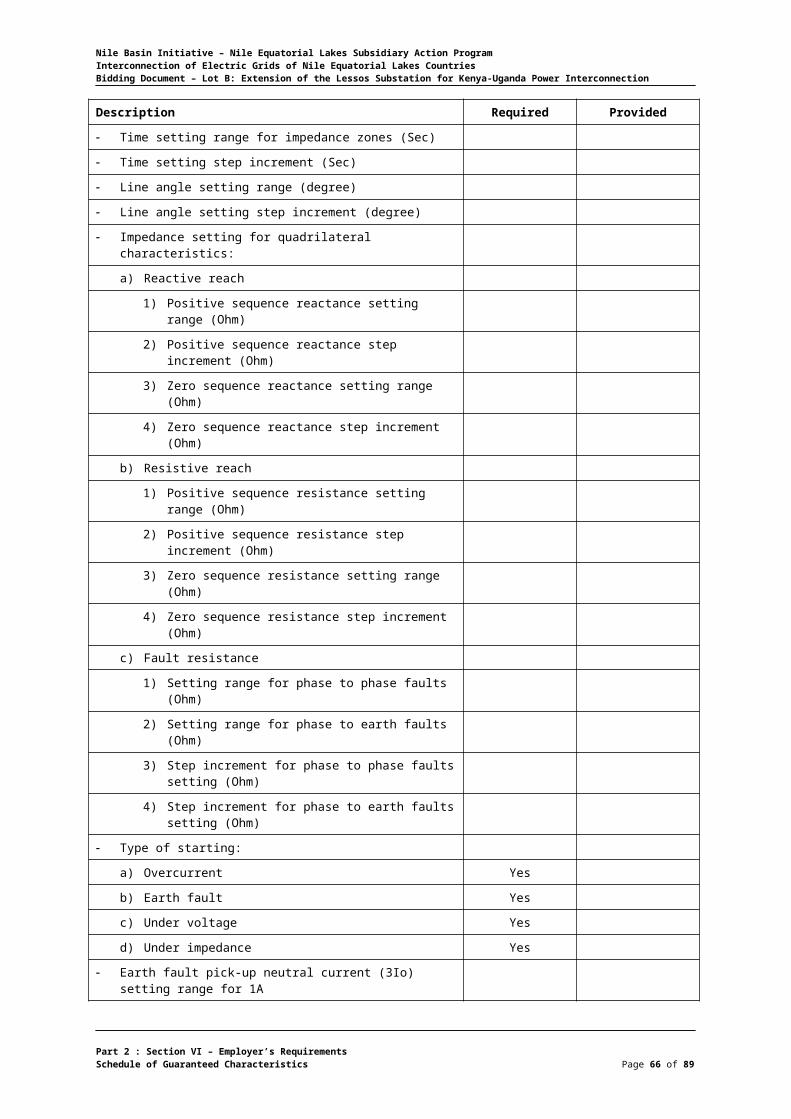
Nile Basin Initiative – Nile Equatorial Lakes Subsidiary Action ProgramInterconnection of Electric Grids of Nile Equatorial Lakes CountriesBidding Document – Lot B: Extension of the Lessos Substation for Kenya-Uganda Power Interconnection
Low Voltage Power Cable
Description Required Provided
LV Power LV Control LV Power LV Control
Manufacturer
Type
Conductor material Cu Cu
Nominal conductor cross section (sq.mm)
Actual conductor cross section (sq.mm)
Outer diameter of conductor (mm)
Type of insulation PVC PVC
Thickness of insulation (mm)
Outer sheath
a) Material PVC PVC
b) Thickness (mm)
Overall diameter of cable (mm)
Bending radius (mm) ≤ 300 ≤ 300
Rated voltage (V)
Highest system voltage (V) 415
Frequency (Hz) 50
D.C. resistance of conductor
a) At 20oC (ohm/km)
Capacitance (nF/km)
Inductance in the required laying configuration (nH/km)
Maximum permissible temperature (0C) 90 90
Maximum permissible short circuit conductor temperature (0C)
250 250
Tan delta at +45oC
Permissible three phase short-circuit current for 1 sec
Permissible phase to earth short-circuit current for 1 sec
Maximum permissible tension when pulling the cable (kg)
A.C. test voltage (kV)
D.C. test voltage (kV)
Dimensions and weights
a) Maximum delivery length per reel (m)
b) Max. gross weight of a full reel (kg
c) Reel dimensions
1) Flange diameter (mm)
2) Core diameter (mm)
Part 2 : Section VI – Employer’s RequirementsSchedule of Guaranteed Characteristics Page 66 of 75

Nile Basin Initiative – Nile Equatorial Lakes Subsidiary Action ProgramInterconnection of Electric Grids of Nile Equatorial Lakes CountriesBidding Document – Lot B: Extension of the Lessos Substation for Kenya-Uganda Power Interconnection
Description Required Provided
LV Power LV Control LV Power LV Control
3) Width (mm)
a) Net weight of the cable (kg/mm)
b) Copper weight (kg/mm)
c) Weight of one sealing end (kg)
Standards applied
Part 2 : Section VI – Employer’s RequirementsSchedule of Guaranteed Characteristics Page 67 of 75
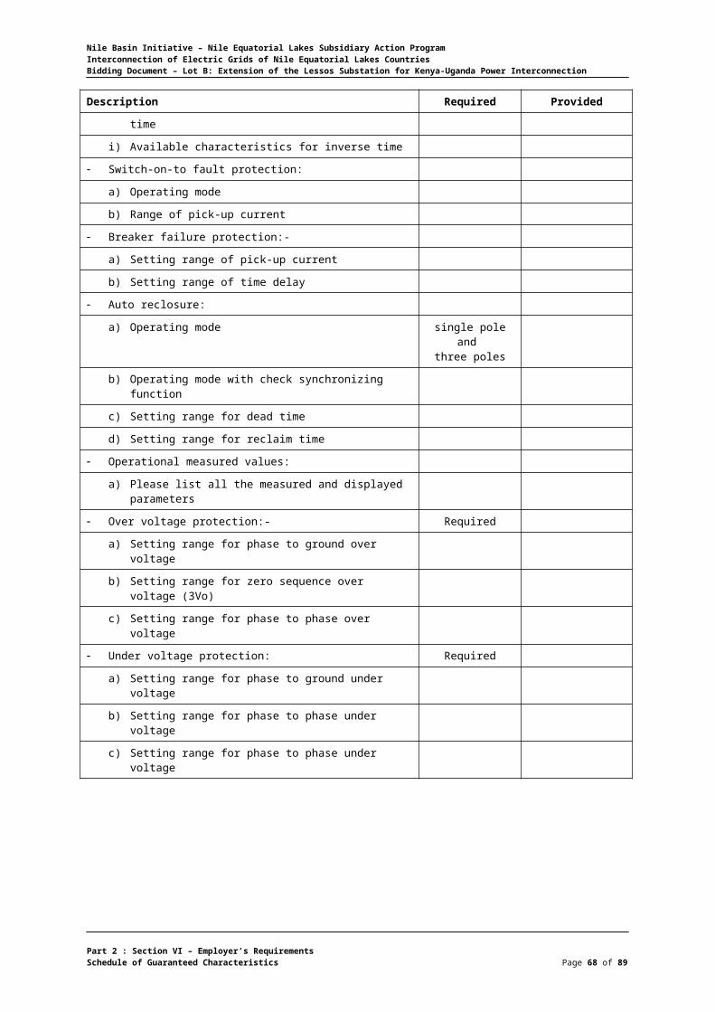
Nile Basin Initiative – Nile Equatorial Lakes Subsidiary Action ProgramInterconnection of Electric Grids of Nile Equatorial Lakes CountriesBidding Document – Lot B: Extension of the Lessos Substation for Kenya-Uganda Power Interconnection
Aluminum Bus Bar
Description Required Provided
Manufacturer
Type
Nominal cross sectional area (sq.mm)
Diameter of bus bar
a) Inner (mm)
b) Outer (mm)
Weight (kg/m)
Resistance at 20oC, ohm/km
Temperature coefficient of linear expansion, (oC)
Current carrying capacity at 20oC, (A)
1-second short time current (rms), (kA) ≥ 31.5
Maximum allowable current at site altitude, (A)
Tensile breaking stress of conductor material , (kg/sq.cm)
Ultimate strength, (kg)
Part 2 : Section VI – Employer’s RequirementsSchedule of Guaranteed Characteristics Page 68 of 75

Nile Basin Initiative – Nile Equatorial Lakes Subsidiary Action ProgramInterconnection of Electric Grids of Nile Equatorial Lakes CountriesBidding Document – Lot B: Extension of the Lessos Substation for Kenya-Uganda Power Interconnection
Post Insulator
Description Required Provided
220kV 132kV 220kV 132kV
Manufacturer
Place of manufacture
Type
Installation outdoor outdoor
Insulator material porcelain porcelain
Rated Voltage (kV) 220 132
Cantilever strength (kg)
Impulse test voltage (1.2/50 microsecond) in kV, at sea level
1050 750
Power frequency 1-minute wet with-stand test voltage (kV), at sea level
460 325
Minimum failing load (bending) (KN)
Minimum failing load (tension) (KN)
Mechanical breaking load (kg)
Minimum guaranteed creepage distance (mm)
6125 3625
Protected creepage distance (mm)
Height of insulation minimum (mm)
Top metal fitting pitch circle diameter (mm)
Bottom metal fitting pitch circle diameter (mm)
Overall dimensions (mm)
Weight (kg)
Standard applied IEC 273 IEC 273
Manufacturers catalogue
Part 2 : Section VI – Employer’s RequirementsSchedule of Guaranteed Characteristics Page 69 of 75
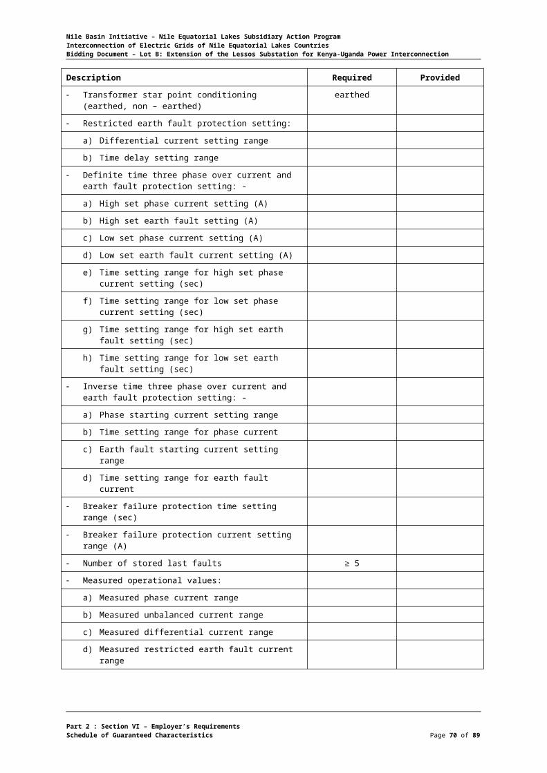
Nile Basin Initiative – Nile Equatorial Lakes Subsidiary Action ProgramInterconnection of Electric Grids of Nile Equatorial Lakes CountriesBidding Document – Lot B: Extension of the Lessos Substation for Kenya-Uganda Power Interconnection
11 kV and 33 kV High Voltage Power Cable
Description Required Provided
11 kV 33 kV 11 kV 33 kV
Manufacturer
Type
Conductor material Cu
Number of Phases
Current rating (A)
Nominal conductor cross section (sq.mm)
Actual conductor cross section (sq.mm)
Outer diameter of conductor (mm)
Type of insulation TR-XLPE
Thickness of insulation (mm)
Type of screen Cu wire
Thickness of screen (mm)
Outer sheath
a) Material
b) Thickness (mm)
Overall diameter of cable (mm)
Bending radius (mm)
Rated voltage (kV) 11 33
Highest system voltage (kV) 12 36
Frequency (Hz) 50 50
D.C. resistance of conductor
a) At 20oC (ohm/km)
Capacitance (nF/km)
Inductance in the required laying configuration (nH/km)
Maximum permissible temperature (0C)
90 90
Maximum permissible short circuit conductor temperature (oC)
Tan delta at +450C
Maximum permissible three phase short-circuit current for 1 second
Maximum permissible phase to earth short-circuit current for 1 second
Maximum permissible tension when pulling the cable (kg)
A.C. test voltage (kV)
D.C. test voltage (kV)
Part 2 : Section VI – Employer’s RequirementsSchedule of Guaranteed Characteristics Page 70 of 75
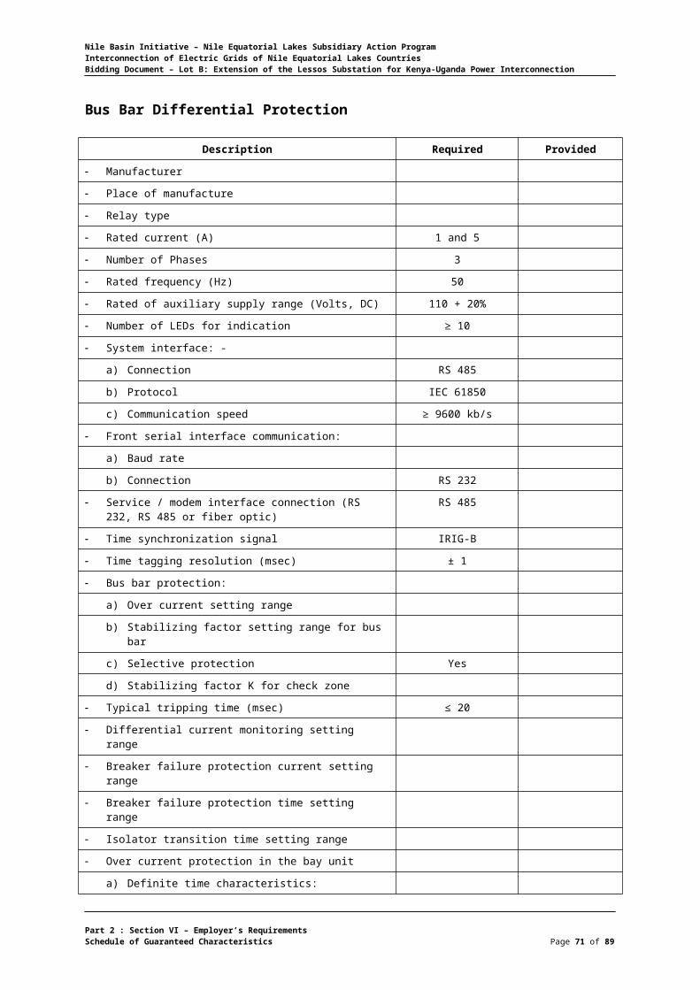
Nile Basin Initiative – Nile Equatorial Lakes Subsidiary Action ProgramInterconnection of Electric Grids of Nile Equatorial Lakes CountriesBidding Document – Lot B: Extension of the Lessos Substation for Kenya-Uganda Power Interconnection
Description Required Provided
11 kV 33 kV 11 kV 33 kV
Dimensions and weights
a) Maximum delivery length per reel (m)
b) Max. gross weight of a full reel (kg)
c) Reel dimensions
d) Flange diameter (mm)
e) Core diameter (mm)
f) Width (mm)
g) Net weight of the cable (kg/mm)
h) Copper weight (kg/mm)
i) Weight of one sealing end (kg)
Standards applied IEC 60502-2 IEC 60502-2
Part 2 : Section VI – Employer’s RequirementsSchedule of Guaranteed Characteristics Page 71 of 75
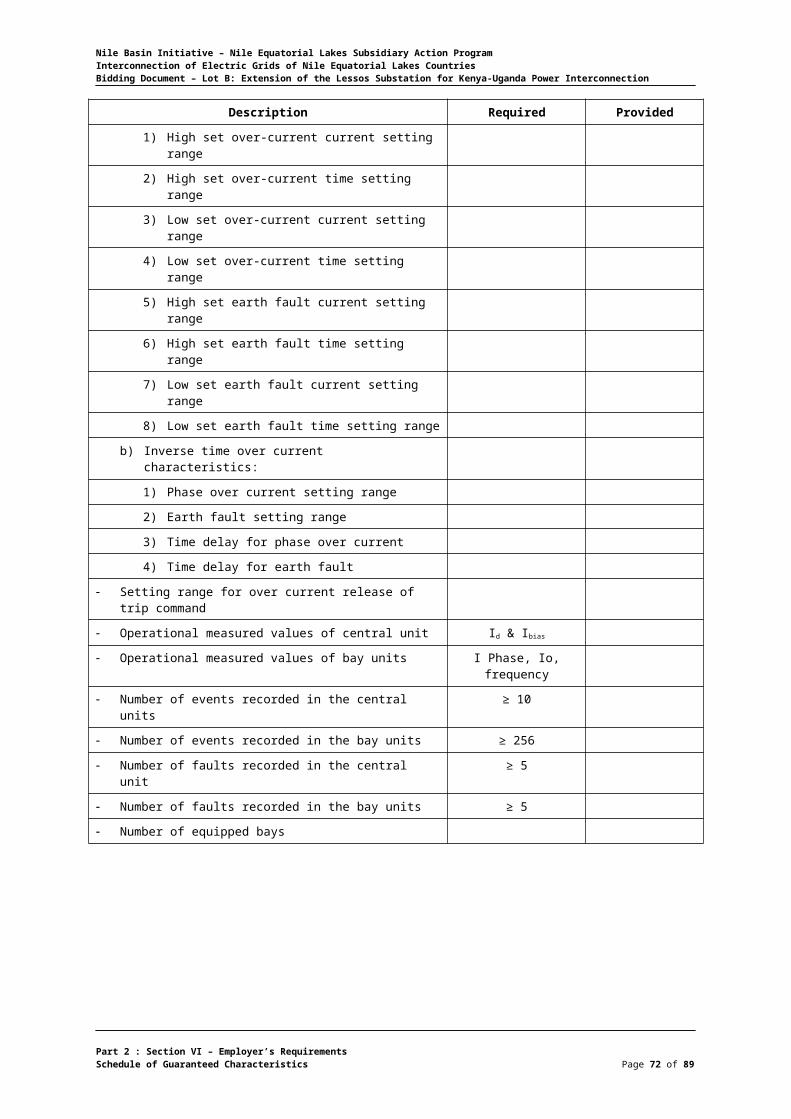
Nile Basin Initiative – Nile Equatorial Lakes Subsidiary Action ProgramInterconnection of Electric Grids of Nile Equatorial Lakes CountriesBidding Document – Lot B: Extension of the Lessos Substation for Kenya-Uganda Power Interconnection
11 kV Metal – Clad Switchboard
Description Required Provided
Manufacturer
Type
Nominal voltage (kV) 11
Highest System voltage (kV) 12
Number of Phases
Bus Bars
a) Current rating (A) 630
b) Cross – section of bus bar (sq.mm)
c) Permissible temperature rise over ambient temperature of 40°C, (°C)
65
d) Permissible temperature rise over ambient temperature of 50˚C, (˚C) (PK-12 only)
e) Type of insulators installed Porcelain
f) Type of material
Thickness of sheet steel used for the cubicle 2-2.5
Dimension of cubicle
a) Width, (mm) < 1500
b) Depth, (mm) < 2400
c) Height, (mm) < 2400
Weight
a) Transformer cubicle, (kg)
b) Line feeder cubicle, (kg)
c) Auxiliary service cubicle, (kg)
d) Moving portion of transformer feeder switchgear assembly, (kg)
Maximum shipping dimensions
a) Length, (mm)
b) Width, (mm)
c) Height, (mm)
Part 2 : Section VI – Employer’s RequirementsSchedule of Guaranteed Characteristics Page 72 of 75

Nile Basin Initiative – Nile Equatorial Lakes Subsidiary Action ProgramInterconnection of Electric Grids of Nile Equatorial Lakes CountriesBidding Document – Lot B: Extension of the Lessos Substation for Kenya-Uganda Power Interconnection
Diesel Generator
Description Required Provided
Manufacturer
Place of manufacture
Type
Capacity 150 kVA
Engine Speed 1500 RPM
Electrical system 12 V DC
Alternator type Brushless-Self Excited
Phase 3
Voltage 240/415 V
Frequency 50 Hz
Starter battery 12 V DC / 100 Ah
Metal Fuel Tank Capacity sufficient for 8 hours but not less than 450
liters
Part 2 : Section VI – Employer’s RequirementsSchedule of Guaranteed Characteristics Page 73 of 75
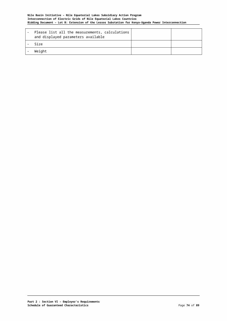
Nile Basin Initiative – Nile Equatorial Lakes Subsidiary Action ProgramInterconnection of Electric Grids of Nile Equatorial Lakes CountriesBidding Document – Lot B: Extension of the Lessos Substation for Kenya-Uganda Power Interconnection
Schedule of Special Tools
Give detailed list of special tools included in the equipment supply.
Item Description Quantity
Part 2 : Section VI – Employer’s RequirementsSchedule of Guaranteed Characteristics Page 74 of 75

Nile Basin Initiative – Nile Equatorial Lakes Subsidiary Action ProgramInterconnection of Electric Grids of Nile Equatorial Lakes CountriesBidding Document – Lot B: Extension of the Lessos Substation for Kenya-Uganda Power Interconnection
Part 2 : Section VI – Employer’s RequirementsSchedule of Guaranteed Characteristics Page 75 of 75