Vehicle Dynamic Monitoring Realtime Distributed Model Implemented
[email protected] [email protected]
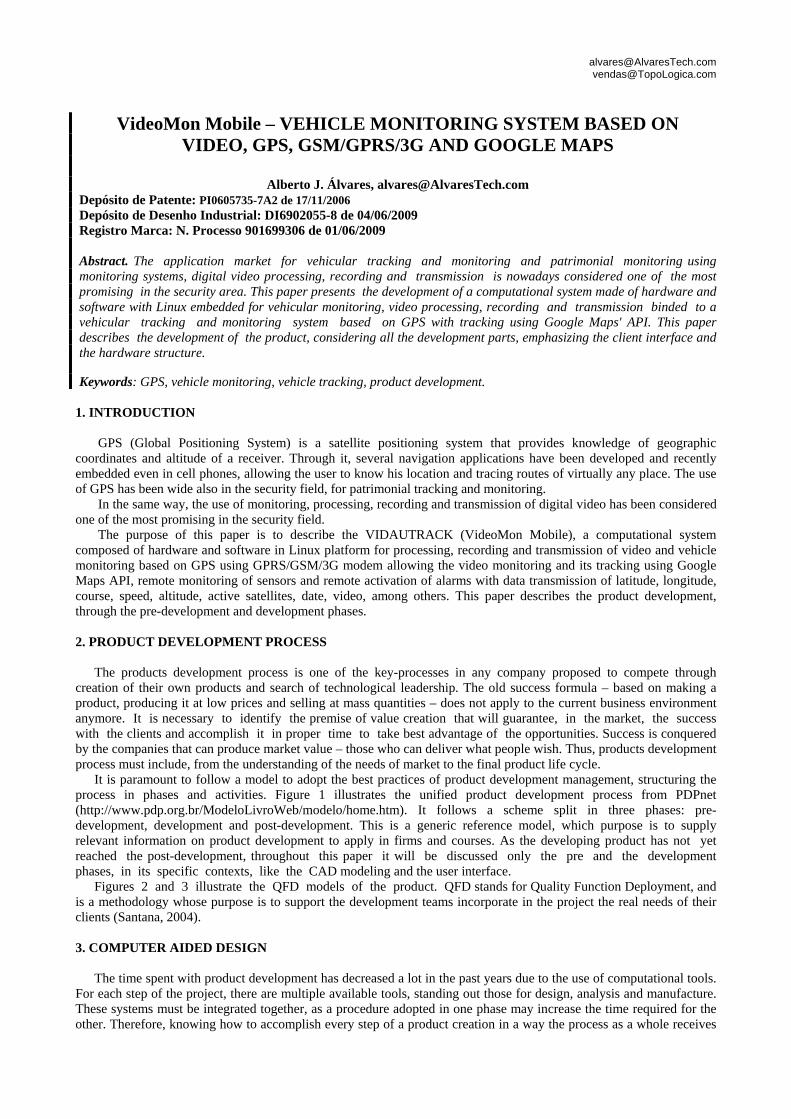
VideoMon Mobile – VEHICLE MONITORING SYSTEM BASED ON VIDEO, GPS, GSM/GPRS/3G AND GOOGLE MAPS
Alberto J. Álvares, [email protected]
Depósito de Patente: PI0605735-7A2 de 17/11/2006 Depósito de Desenho Industrial: DI6902055-8 de 04/06/2009 Registro Marca: N. Processo 901699306 de 01/06/2009 Abstract. The application market for vehicular tracking and monitoring and patrimonial monitoring using monitoring systems, digital video processing, recording and transmission is nowadays considered one of the most promising in the security area. This paper presents the development of a computational system made of hardware and software with Linux embedded for vehicular monitoring, video processing, recording and transmission binded to a vehicular tracking and monitoring system based on GPS with tracking using Google Maps' API. This paper describes the development of the product, considering all the development parts, emphasizing the client interface and the hardware structure. Keywords: GPS, vehicle monitoring, vehicle tracking, product development.
1. INTRODUCTION
GPS (Global Positioning System) is a satellite positioning system that provides knowledge of geographic
coordinates and altitude of a receiver. Through it, several navigation applications have been developed and recently embedded even in cell phones, allowing the user to know his location and tracing routes of virtually any place. The use of GPS has been wide also in the security field, for patrimonial tracking and monitoring.
In the same way, the use of monitoring, processing, recording and transmission of digital video has been considered one of the most promising in the security field.
The purpose of this paper is to describe the VIDAUTRACK (VideoMon Mobile), a computational system composed of hardware and software in Linux platform for processing, recording and transmission of video and vehicle monitoring based on GPS using GPRS/GSM/3G modem allowing the video monitoring and its tracking using Google Maps API, remote monitoring of sensors and remote activation of alarms with data transmission of latitude, longitude, course, speed, altitude, active satellites, date, video, among others. This paper describes the product development, through the pre-development and development phases. 2. PRODUCT DEVELOPMENT PROCESS
The products development process is one of the key-processes in any company proposed to compete through
creation of their own products and search of technological leadership. The old success formula – based on making a product, producing it at low prices and selling at mass quantities – does not apply to the current business environment anymore. It is necessary to identify the premise of value creation that will guarantee, in the market, the success with the clients and accomplish it in proper time to take best advantage of the opportunities. Success is conquered by the companies that can produce market value – those who can deliver what people wish. Thus, products development process must include, from the understanding of the needs of market to the final product life cycle.
It is paramount to follow a model to adopt the best practices of product development management, structuring the process in phases and activities. Figure 1 illustrates the unified product development process from PDPnet (http://www.pdp.org.br/ModeloLivroWeb/modelo/home.htm). It follows a scheme split in three phases: pre-development, development and post-development. This is a generic reference model, which purpose is to supply relevant information on product development to apply in firms and courses. As the developing product has not yet reached the post-development, throughout this paper it will be discussed only the pre and the development phases, in its specific contexts, like the CAD modeling and the user interface.
Figures 2 and 3 illustrate the QFD models of the product. QFD stands for Quality Function Deployment, and is a methodology whose purpose is to support the development teams incorporate in the project the real needs of their clients (Santana, 2004).
3. COMPUTER AIDED DESIGN
The time spent with product development has decreased a lot in the past years due to the use of computational tools.
For each step of the project, there are multiple available tools, standing out those for design, analysis and manufacture. These systems must be integrated together, as a procedure adopted in one phase may increase the time required for the other. Therefore, knowing how to accomplish every step of a product creation in a way the process as a whole receives
[email protected] [email protected]
benefits is paramount to the reduction of time in product development. With the arrival of the first CAD (Computer Aided Design) systems that allowed parametric tridimensional modeling based on features, the way of conceiving a project has changed substantially.
Figure 1: PDPnet development process (http://www.pdp.org.br/ModeloLivroWeb/modelo/home.htm).
Figure 2: QFD: Part Planning. Figure 3: QFD: Product Planning. One of the main advantages in the use of 3D CAD systems is the interactivity with other fields. The model can be
used to calculate its volume, mass properties and momentum, assembling, check interferences, generate drawings, simulate its mechanical behavior, quick prototyping, CNC machining, and so on (Foggiato et al., 2008).
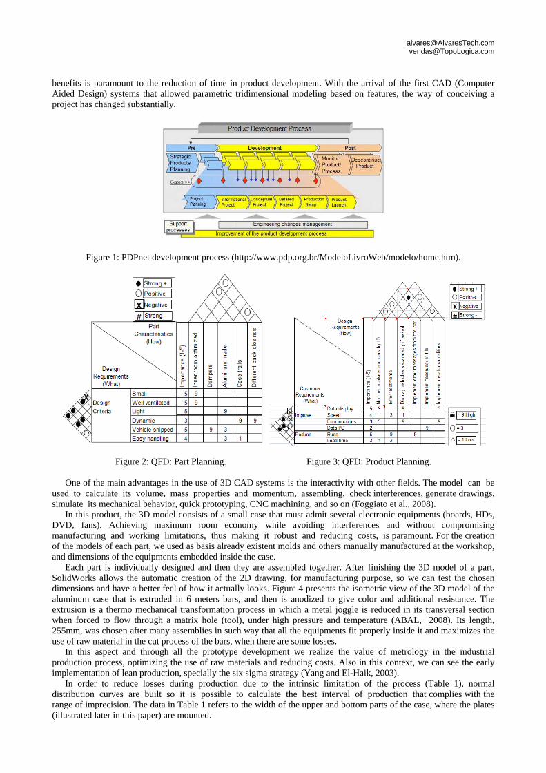
In this product, the 3D model consists of a small case that must admit several electronic equipments (boards, HDs, DVD, fans). Achieving maximum room economy while avoiding interferences and without compromising manufacturing and working limitations, thus making it robust and reducing costs, is paramount. For the creation of the models of each part, we used as basis already existent molds and others manually manufactured at the workshop, and dimensions of the equipments embedded inside the case.
Each part is individually designed and then they are assembled together. After finishing the 3D model of a part, SolidWorks allows the automatic creation of the 2D drawing, for manufacturing purpose, so we can test the chosen dimensions and have a better feel of how it actually looks. Figure 4 presents the isometric view of the 3D model of the aluminum case that is extruded in 6 meters bars, and then is anodized to give color and additional resistance. The extrusion is a thermo mechanical transformation process in which a metal joggle is reduced in its transversal section when forced to flow through a matrix hole (tool), under high pressure and temperature (ABAL, 2008). Its length, 255mm, was chosen after many assemblies in such way that all the equipments fit properly inside it and maximizes the use of raw material in the cut process of the bars, when there are some losses.
In this aspect and through all the prototype development we realize the value of metrology in the industrial production process, optimizing the use of raw materials and reducing costs. Also in this context, we can see the early implementation of lean production, specially the six sigma strategy (Yang and El-Haik, 2003).
In order to reduce losses during production due to the intrinsic limitation of the process (Table 1), normal distribution curves are built so it is possible to calculate the best interval of production that complies with the range of imprecision. The data in Table 1 refers to the width of the upper and bottom parts of the case, where the plates (illustrated later in this paper) are mounted.
[email protected] [email protected]
Figure 4: The case.
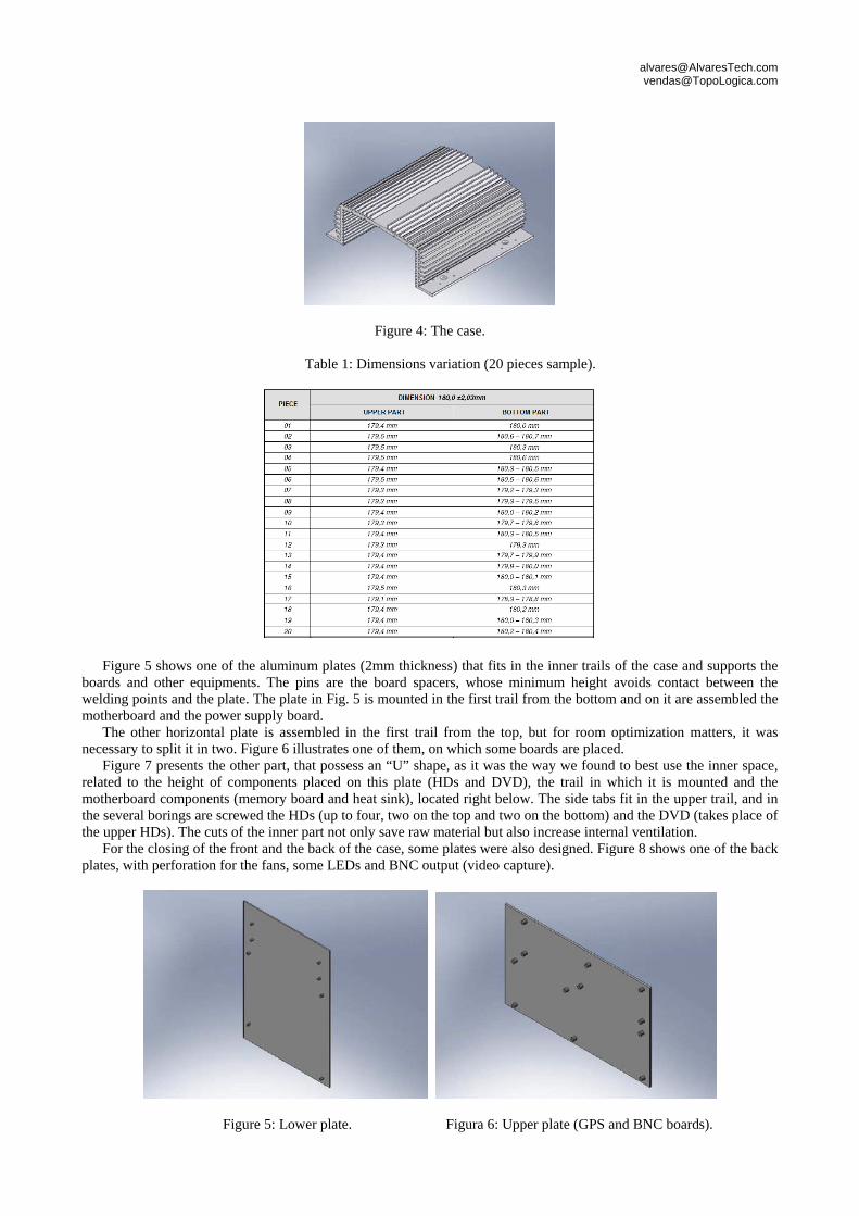
Table 1: Dimensions variation (20 pieces sample).
Figure 5 shows one of the aluminum plates (2mm thickness) that fits in the inner trails of the case and supports the boards and other equipments. The pins are the board spacers, whose minimum height avoids contact between the welding points and the plate. The plate in Fig. 5 is mounted in the first trail from the bottom and on it are assembled the motherboard and the power supply board.
The other horizontal plate is assembled in the first trail from the top, but for room optimization matters, it was necessary to split it in two. Figure 6 illustrates one of them, on which some boards are placed.
Figure 7 presents the other part, that possess an “U” shape, as it was the way we found to best use the inner space, related to the height of components placed on this plate (HDs and DVD), the trail in which it is mounted and the motherboard components (memory board and heat sink), located right below. The side tabs fit in the upper trail, and in the several borings are screwed the HDs (up to four, two on the top and two on the bottom) and the DVD (takes place of the upper HDs). The cuts of the inner part not only save raw material but also increase internal ventilation.
For the closing of the front and the back of the case, some plates were also designed. Figure 8 shows one of the back plates, with perforation for the fans, some LEDs and BNC output (video capture).
Figure 5: Lower plate. Figura 6: Upper plate (GPS and BNC boards).
[email protected] [email protected]
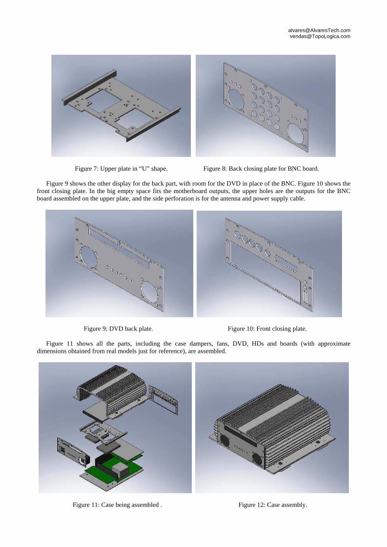
Figure 7: Upper plate in “U” shape. Figure 8: Back closing plate for BNC board. Figure 9 shows the other display for the back part, with room for the DVD in place of the BNC. Figure 10 shows the
front closing plate. In the big empty space fits the motherboard outputs, the upper holes are the outputs for the BNC board assembled on the upper plate, and the side perforation is for the antenna and power supply cable.
Figure 9: DVD back plate. Figure 10: Front closing plate.
Figure 11 shows all the parts, including the case dampers, fans, DVD, HDs and boards (with approximate dimensions obtained from real models just for reference), are assembled.
Figure 11: Case being assembled . Figure 12: Case assembly.
[email protected] [email protected]
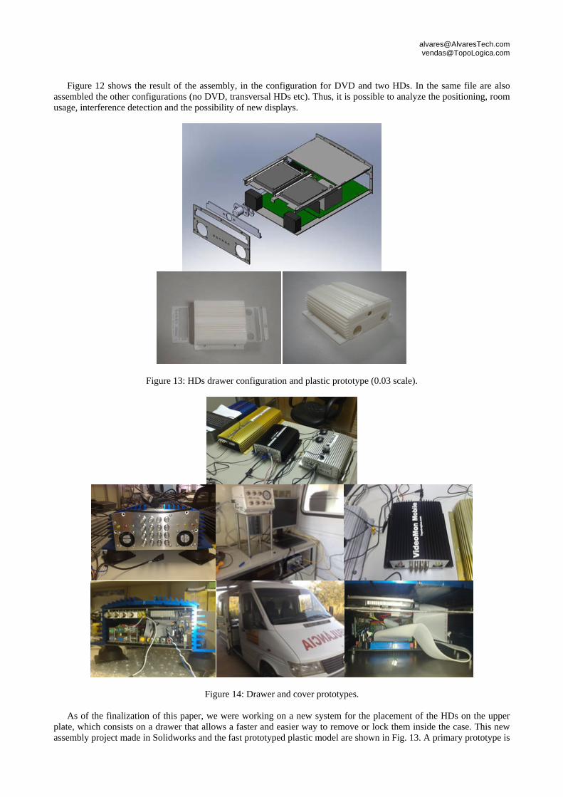
Figure 12 shows the result of the assembly, in the configuration for DVD and two HDs. In the same file are also assembled the other configurations (no DVD, transversal HDs etc). Thus, it is possible to analyze the positioning, room usage, interference detection and the possibility of new displays.
Figure 13: HDs drawer configuration and plastic prototype (0.03 scale).
Figure 14: Drawer and cover prototypes.
As of the finalization of this paper, we were working on a new system for the placement of the HDs on the upper plate, which consists on a drawer that allows a faster and easier way to remove or lock them inside the case. This new assembly project made in Solidworks and the fast prototyped plastic model are shown in Fig. 13. A primary prototype is
[email protected] [email protected]
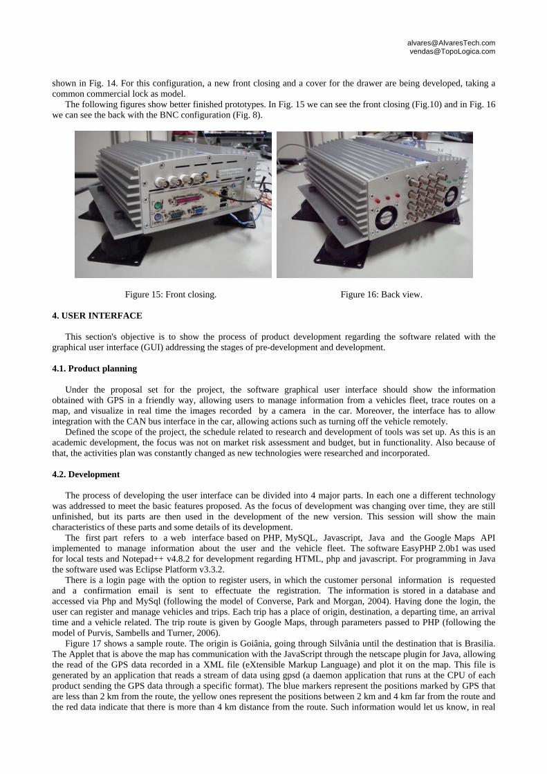
shown in Fig. 14. For this configuration, a new front closing and a cover for the drawer are being developed, taking a common commercial lock as model.
The following figures show better finished prototypes. In Fig. 15 we can see the front closing (Fig.10) and in Fig. 16 we can see the back with the BNC configuration (Fig. 8).
Figure 15: Front closing. Figure 16: Back view.
4. USER INTERFACE
This section's objective is to show the process of product development regarding the software related with the graphical user interface (GUI) addressing the stages of pre-development and development. 4.1. Product planning
Under the proposal set for the project, the software graphical user interface should show the information
obtained with GPS in a friendly way, allowing users to manage information from a vehicles fleet, trace routes on a map, and visualize in real time the images recorded by a camera in the car. Moreover, the interface has to allow integration with the CAN bus interface in the car, allowing actions such as turning off the vehicle remotely.
Defined the scope of the project, the schedule related to research and development of tools was set up. As this is an academic development, the focus was not on market risk assessment and budget, but in functionality. Also because of that, the activities plan was constantly changed as new technologies were researched and incorporated.
4.2. Development
The process of developing the user interface can be divided into 4 major parts. In each one a different technology
was addressed to meet the basic features proposed. As the focus of development was changing over time, they are still unfinished, but its parts are then used in the development of the new version. This session will show the main characteristics of these parts and some details of its development.
The first part refers to a web interface based on PHP, MySQL, Javascript, Java and the Google Maps API implemented to manage information about the user and the vehicle fleet. The software EasyPHP 2.0b1 was used for local tests and Notepad++ v4.8.2 for development regarding HTML, php and javascript. For programming in Java the software used was Eclipse Platform v3.3.2.
There is a login page with the option to register users, in which the customer personal information is requested and a confirmation email is sent to effectuate the registration. The information is stored in a database and accessed via Php and MySql (following the model of Converse, Park and Morgan, 2004). Having done the login, the user can register and manage vehicles and trips. Each trip has a place of origin, destination, a departing time, an arrival time and a vehicle related. The trip route is given by Google Maps, through parameters passed to PHP (following the model of Purvis, Sambells and Turner, 2006).
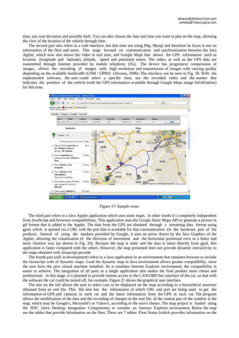
Figure 17 shows a sample route. The origin is Goiânia, going through Silvânia until the destination that is Brasilia. The Applet that is above the map has communication with the JavaScript through the netscape plugin for Java, allowing the read of the GPS data recorded in a XML file (eXtensible Markup Language) and plot it on the map. This file is generated by an application that reads a stream of data using gpsd (a daemon application that runs at the CPU of each product sending the GPS data through a specific format). The blue markers represent the positions marked by GPS that are less than 2 km from the route, the yellow ones represent the positions between 2 km and 4 km far from the route and the red data indicate that there is more than 4 km distance from the route. Such information would let us know, in real
[email protected] [email protected]
time, any rout deviation and possible theft. You can also choose the date and time you want to plot on the map, allowing the view of the location of the vehicle through time.
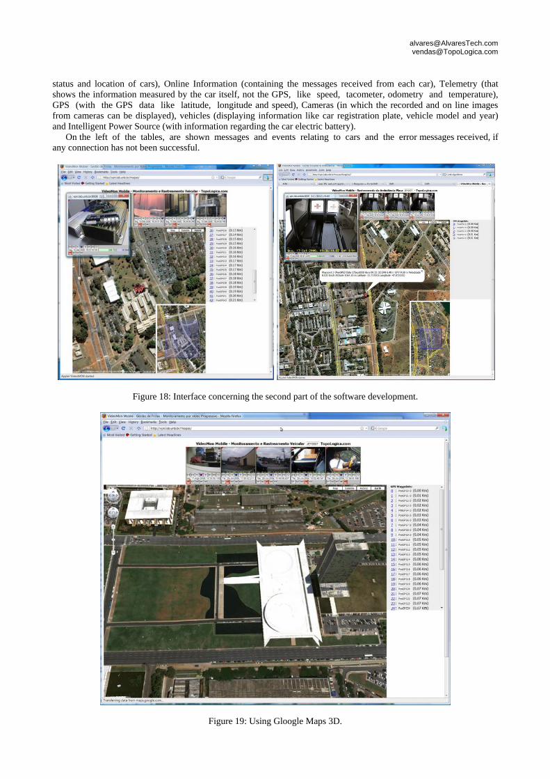
The second part also refers to a web interface, but this time not using Php, Mysql and therefore its focus is not on information of the fleet and users. This stage focused on communication and synchronization between the Java Applet, which now also shows the video in real time, and Google Maps that shows the GPS information such as location (longitude and latitude), altitude, speed and positional errors. The video, as well as the GPS data are transmitted through Internet provided by mobile telephony (3G). The device has progressive compression of images, allows the recording of images with high resolution and transmission of images with varying quality depending on the available bandwidth (GSM / GPRS) (Alvares, 2006). The interface can be seen in Fig. 18. With the implemented software, the user could select a specific time, see the recorded video and the marker that indicates the position of the vehicle (with the GPS information available through Google Maps image InfoWindow) for this time.
Figure 17: Sample route.
The third part refers to a Java Applet application which uses static maps. In other words it’s completely independent from JavaScript and browsers compatibilities. This application uses the Google Static Maps API to generate a picture in gif format that is added to the Applet. The data from the GPS are obtained through a streaming data format using gpsd, which is opened via a URL with the port that is available for that communication (in the hardware part of the product). Instead of using the markers provided by Google, it uses an arrow drawn by the Java Graphics of the Applet, allowing the visualization of the direction of movement and the horizontal positional error in a faster and more intuitive way (as shown in Fig. 20). Because the map is static and the data is taken directly from gpsd, this application is faster compared with the others. However, the map presented does not provide dynamic interactivity to the maps obtained with Javascript provide.
The fourth part (still in development) refers to a Java application in an environment that emulates browser to include the Javascript code of dynamic maps. Load the dynamic map in Java environment allows greater compatibility, since the user have the java virtual machine installed. As it emulates Internet Explorer environment, the compatibility is easier to achieve. The integration of all parts in a single application also makes the final product more robust and professional. In this stage, it is planned to provide remote access to the CAN/OBD bus interface of the car, so that with the software the car could be turned off, for example. Figure 21 shows the graphical user interface.
The tree on the left allows the user to select cars to be displayed on the map according to a hierarchical structure obtained from an xml file. This file also has the information of which URL and port are being used to get the information of GPS and cameras in each car and the latest information from the GPS in each car. The program allows the modification of the data and the recording of changes in the xml file. In the central part of the window is the map, which may be Google's, Microsoft's or Yahoo's, according to the user's choice. The map project is loaded using the JDIC (Java Desktop Integration Components) to emulate an Internet Explorer environment. Below the map are the tables that provide information on the fleet. There are 7 tables: Fleet Status (which provides information on the
[email protected] [email protected]
status and location of cars), Online Information (containing the messages received from each car), Telemetry (that shows the information measured by the car itself, not the GPS, like speed, tacometer, odometry and temperature), GPS (with the GPS data like latitude, longitude and speed), Cameras (in which the recorded and on line images from cameras can be displayed), vehicles (displaying information like car registration plate, vehicle model and year) and Intelligent Power Source (with information regarding the car electric battery).
On the left of the tables, are shown messages and events relating to cars and the error messages received, if any connection has not been successful.
Figure 18: Interface concerning the second part of the software development.
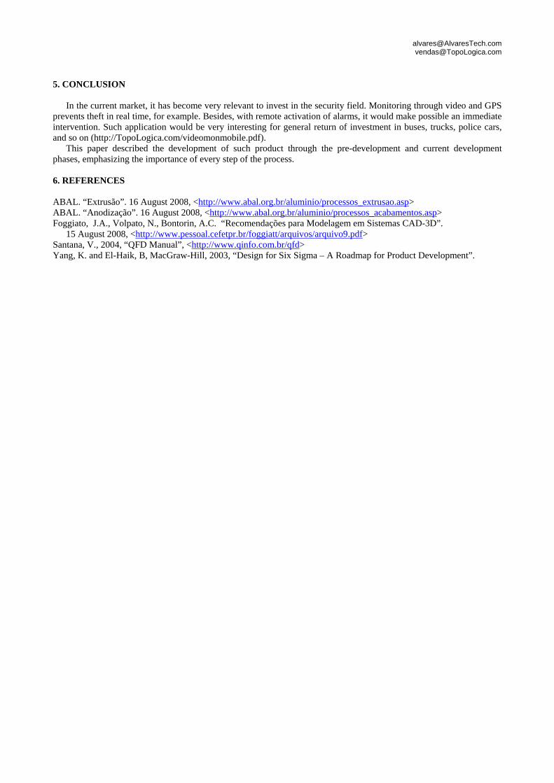
Figure 19: Using Gloogle Maps 3D.

[email protected] [email protected]
Figure 20: Interface of the thrird part of the software development.
Figure 21: Interface of the fourth part of the software development.
[email protected] [email protected]
5. CONCLUSION In the current market, it has become very relevant to invest in the security field. Monitoring through video and GPS
prevents theft in real time, for example. Besides, with remote activation of alarms, it would make possible an immediate intervention. Such application would be very interesting for general return of investment in buses, trucks, police cars, and so on (http://TopoLogica.com/videomonmobile.pdf).
This paper described the development of such product through the pre-development and current development phases, emphasizing the importance of every step of the process. 6. REFERENCES
ABAL. “Extrusão”. 16 August 2008, <http://www.abal.org.br/aluminio/processos_extrusao.asp> ABAL. “Anodização”. 16 August 2008, <http://www.abal.org.br/aluminio/processos_acabamentos.asp> Foggiato, J.A., Volpato, N., Bontorin, A.C. “Recomendações para Modelagem em Sistemas CAD-3D”.
15 August 2008, <http://www.pessoal.cefetpr.br/foggiatt/arquivos/arquivo9.pdf> Santana, V., 2004, “QFD Manual”, <http://www.qinfo.com.br/qfd> Yang, K. and El-Haik, B, MacGraw-Hill, 2003, “Design for Six Sigma – A Roadmap for Product Development”.