Video Surveillance and IP Storage - Intransa Surveillance System Performance and Frame Loss...
24
www.intransa.com 1 Video Surveillance and IP Storage A White Paper with Genetec Omnicast And Intransa Scalable, External IP Storage
Transcript of Video Surveillance and IP Storage - Intransa Surveillance System Performance and Frame Loss...
www.intransa.com 1
Video Surveillance and IP Storage
A White Paper with Genetec Omnicast And
Intransa Scalable, External IP Storage
www.intransa.com 2
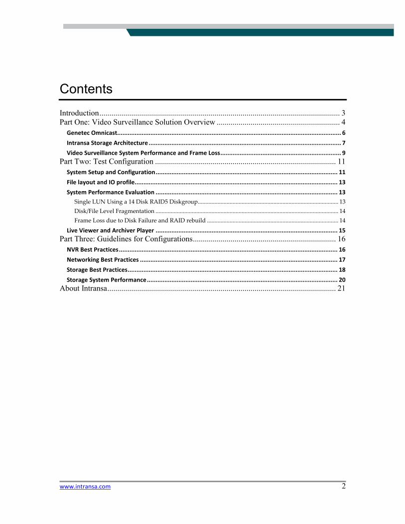
Contents
Introduction......................................................................................................................... 3
Part One: Video Surveillance Solution Overview .............................................................. 4
Genetec Omnicast................................................................................................................................ 6
Intransa Storage Architecture .............................................................................................................. 7
Video Surveillance System Performance and Frame Loss..................................................................... 9 Part Two: Test Configuration ........................................................................................... 11
System Setup and Configuration........................................................................................................ 11
File layout and IO profile.................................................................................................................... 13
System Performance Evaluation ........................................................................................................ 13
Single LUN Using a 14 Disk RAID5 Diskgroup............................................................................................. 13
Disk/File Level Fragmentation ......................................................................................................................... 14
Frame Loss due to Disk Failure and RAID rebuild ....................................................................................... 14
Live Viewer and Archiver Player ........................................................................................................ 15 Part Three: Guidelines for Configurations........................................................................ 16
NVR Best Practices............................................................................................................................. 16
Networking Best Practices ................................................................................................................. 17
Storage Best Practices........................................................................................................................ 18
Storage System Performance............................................................................................................. 20 About Intransa................................................................................................................... 21

www.intransa.com 3
Introduction When it comes to disk storage to video surveillance systems, most security practitioners only think about storage capacity in terms of DVRs and NVRs. And worst of all, most of the time, storage is thought of only after the rest of the surveillance system has been designed and purchased. This can be a costly mistake, not only because DVRs and NVRs typically use fixed, captive storage instead of more cost effective, scalable and reliable shared, external IP storage, but also because not all storage performance is equal. This report looks at the issues, shows performance limitations and results, and then demonstrates how a powerful video management system such as the Genetec Omnicast application can leverage Intransa Shared, External IP Storage much more effectively than DVR/NVR fixed captive storage. Testing was performed on a real, functioning video surveillance system with components from Genetec, Intransa, AXIS Communications, Dell, and other vendors, a strong example of an IP based system with multi-vendor interoperability. The report closes with recommendations on best practices for enabling a video surveillance system with Genetec Omnicast.
www.intransa.com 4
Part One: Video Surveillance Solution Overview
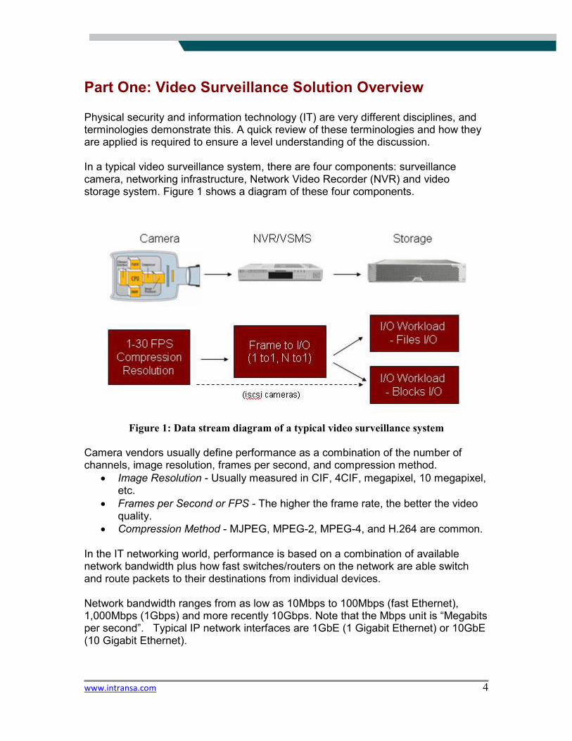
Physical security and information technology (IT) are very different disciplines, and terminologies demonstrate this. A quick review of these terminologies and how they are applied is required to ensure a level understanding of the discussion. In a typical video surveillance system, there are four components: surveillance camera, networking infrastructure, Network Video Recorder (NVR) and video storage system. Figure 1 shows a diagram of these four components.
Figure 1: Data stream diagram of a typical video surveillance system
Camera vendors usually define performance as a combination of the number of channels, image resolution, frames per second, and compression method.
• Image Resolution - Usually measured in CIF, 4CIF, megapixel, 10 megapixel, etc.
• Frames per Second or FPS - The higher the frame rate, the better the video quality.
• Compression Method - MJPEG, MPEG-2, MPEG-4, and H.264 are common. In the IT networking world, performance is based on a combination of available network bandwidth plus how fast switches/routers on the network are able switch and route packets to their destinations from individual devices. Network bandwidth ranges from as low as 10Mbps to 100Mbps (fast Ethernet), 1,000Mbps (1Gbps) and more recently 10Gbps. Note that the Mbps unit is “Megabits per second”. Typical IP network interfaces are 1GbE (1 Gigabit Ethernet) or 10GbE (10 Gigabit Ethernet).

www.intransa.com 5
For switches/routers, performance is related to how many packets per second the device can switch toward its destination and what is the latency or delay for each packet to transverse the switching device. The NVR is the engine of the modern video surveillance system. The NVR manages the cameras as well as storage system. The NVR receives frames from various cameras, converts the frames into IOs (Input/Output operations), and then writes the IOs to the storage system. There are two ways NVRs write to storage: DVRs can directly write to a storage block device (a disk drive), or they can write to the storage device (disk drive) through a file system. For Windows-based NVRs, the NTFS (Net Technology File System) file system is typically used. The ext3 (Third Extended File System) file system is common for Linux-based NVRs. For more definitions and specific details of video surveillance, IT and storage terms, Intransa provides an extensive Glossary of Terms at http://www.intransa.com/technology/glossary.php, useful for those interested in either IT or physical security terminology. Storage is the last mile of the video surveillance system, where the rubber meets the road. Video frames from cameras are passed from the NVR to the storage system as IOs. This translates in the IT storage world to IO workload. The pattern used by IOs to access the storage system has a huge effect on the storage system performance which again determines the overall system performance. The list of parameters for IO workload includes: request block size (typically in the unit of KB or Kilobyte), random or sequential actions, read write ratio, etc. When it comes to the storage IO transport, the terms most pertinent are SCSI (Small Computer System Interface), FC (Fibre Channel), SAS (Serial Attached Storage) and iSCSI (SCSI over IP protocol). The device that actually stores the video is disk drive. Common current disk drive types are SATA (Serial ATA or Serial Advanced Technology Attachment), SAS (Serial Attached SCSI) and FC (Fibre Channel). Disk drives are differentiated along the lines of performance, capacity and reliability. Storage systems provide virtualized storage to the NVR, and provide data loss protection through RAID (Redundant Array of Independent Disks). The performance terminology for storage is typically measured units of MBps (Megabytes), for throughput and IOPS (IOs per second).
www.intransa.com 6
Genetec Omnicast
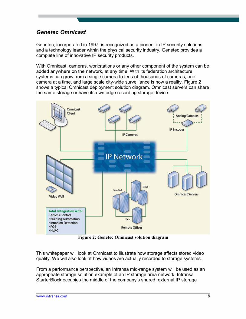
Genetec, incorporated in 1997, is recognized as a pioneer in IP security solutions and a technology leader within the physical security industry. Genetec provides a complete line of innovative IP security products. With Omnicast, cameras, workstations or any other component of the system can be added anywhere on the network, at any time. With its federation architecture, systems can grow from a single camera to tens of thousands of cameras, one camera at a time, and large scale city-wide surveillance is now a reality. Figure 2 shows a typical Omnicast deployment solution diagram. Omnicast servers can share the same storage or have its own edge recording storage device.
Figure 2: Genetec Omnicast solution diagram
This whitepaper will look at Omnicast to illustrate how storage affects stored video quality. We will also look at how videos are actually recorded to storage systems. From a performance perspective, an Intransa mid-range system will be used as an appropriate storage solution example of an IP storage area network. Intransa StarterBlock occupies the middle of the company’s shared, external IP storage
www.intransa.com 7
family, with more system throughput and capacity than either the edge recording platform StarterBlock or the departmental EdgeBlock series. A single Intransa StorStac BuildingBlock system is able to support 440 cameras with 30FPS 4CIF MJPEG compression [13200 FPS]. The high end of the Intransa product line, single PerformanceBlock system, can support 3,500 cameras at similar compression rates [65,000 FPS]. With such capability for scaling to huge online video repositories, Intransa enables Genetec Omnicast for large scale video surveillance deployment.
Intransa Storage Architecture
Intransa StorStac BuildingBlock systems consist of two independently scalable components, integrated form a complete IP-based storage area network (SAN) platform for recording of video and data. These components are:
� Performance Controller Units or PCUs � Storage Capacity Enclosures or SCEs
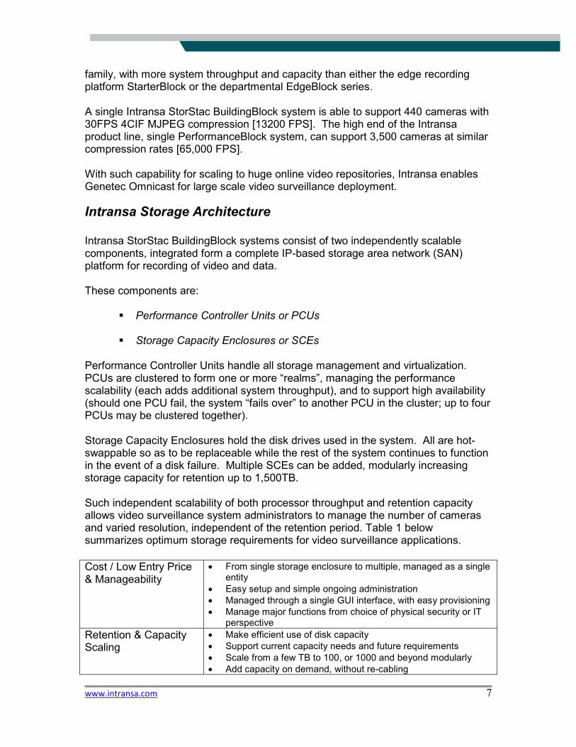
Performance Controller Units handle all storage management and virtualization. PCUs are clustered to form one or more “realms”, managing the performance scalability (each adds additional system throughput), and to support high availability (should one PCU fail, the system “fails over” to another PCU in the cluster; up to four PCUs may be clustered together). Storage Capacity Enclosures hold the disk drives used in the system. All are hot-swappable so as to be replaceable while the rest of the system continues to function in the event of a disk failure. Multiple SCEs can be added, modularly increasing storage capacity for retention up to 1,500TB. Such independent scalability of both processor throughput and retention capacity allows video surveillance system administrators to manage the number of cameras and varied resolution, independent of the retention period. Table 1 below summarizes optimum storage requirements for video surveillance applications.
Cost / Low Entry Price & Manageability
• From single storage enclosure to multiple, managed as a single entity
• Easy setup and simple ongoing administration
• Managed through a single GUI interface, with easy provisioning
• Manage major functions from choice of physical security or IT perspective
Retention & Capacity Scaling
• Make efficient use of disk capacity
• Support current capacity needs and future requirements
• Scale from a few TB to 100, or 1000 and beyond modularly
• Add capacity on demand, without re-cabling
www.intransa.com 8
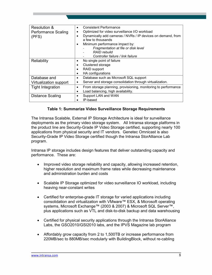
Table 1: Summarize Video Surveillance Storage Requirements
The Intransa Scalable, External IP Storage Architecture is ideal for surveillance deployments as the primary video storage system. All Intransa storage platforms in the product line are Security-Grade IP Video Storage certified, supporting nearly 100 applications from physical security and IT vendors. Genetec Omnicast is also Security-Grade IP Video Storage certified though the Intransa StorAlliance Lab program. Intransa IP storage includes design features that deliver outstanding capacity and performance. These are:
• Improved video storage reliability and capacity, allowing increased retention, higher resolution and maximum frame rates while decreasing maintenance and administration burden and costs
• Scalable IP Storage optimized for video surveillance IO workload, including heaving near-constant writes
• Certified for enterprise-grade IT storage for varied applications including consolidation and virtualization with VMware™ ESX, & Microsoft operating systems, Microsoft Exchange™ (2003 & 2007) & Microsoft SQL Server™, plus applications such as VTL and disk-to-disk backup and data warehousing
• Certified for physical security applications through the Intransa StorAlliance Labs, the GSO2010/GSI2010 labs, and the IPVS Magazine lab program
• Affordably grow capacity from 2 to 1,500TB or increase performance from 220MB/sec to 880MB/sec modularly with BuildingBlock, without re-cabling
Resolution & Performance Scaling (PFS)
• Consistent Performance
• Optimized for video surveillance I/O workload
• Dynamically add cameras / NVRs / IP devices on demand, from a few to thousands
• Minimum performance impact by: - Fragmentation at file or disk level - RAID rebuild - Controller failure / link failure
Reliability • No single point of failure
• Clustered storage
• RAID support
• HA configurations
Database and Virtualization support
• Database such as Microsoft SQL support
• Server and storage consolidation through virtualization.
Tight Integration • From storage planning, provisioning, monitoring to performance
• Load balancing, high availability.
Distance Scaling • Support LAN and WAN
• IP-based
www.intransa.com 9
• Advanced RAID 0, 1, 5, 6 and 10 protection, high availability configurations, and hot-swap disk drives, fans, power supplies and major components
Video Surveillance System Performance and Frame Loss
Unintended video frame loss is common in many video storage systems today, typically caused by one of just two factors. First, the storage system may not be able to keep up with the video data rate due to the number of cameras, compression, and resolution and frame rate settings employed. Or the problem may be because the network video recorder (NVR) can not process the all of video frames in a timely manner. Dropping frames in video applications may have been tolerable in some application environments, exhibited in behavior such as a nearly unnoticeable picture freeze. However, more and more security practitioners and their end user customers are finding continued frame loss unacceptable. Often, frames drop more as more cameras with higher resolution are added to the surveillance system. From storage system prospective, physical security system designers should consider this and the impact that the design will have on performance when it comes to system scalability and stored video quality. How do we define the recorded video quality for a video surveillance application? For many applications, only recorded video is meaningful, so measuring frame losses is a measure of the recorded video quality. The recorded video quality can be considered a total system scalability measurement. It can be impacted by the number of cameras, FPS, resolution, NVR configuration and the underlying storage system. Since video is a continuous streaming application, we will need to use a statistical sampling method to quantify the recorded video quality. The cumulative percentage of recorded frames fits nicely into describing video quality, since applications have different tolerances and requirements for video quality. For this paper, we will use two parameters:
• Total Frame Loss (TFL)
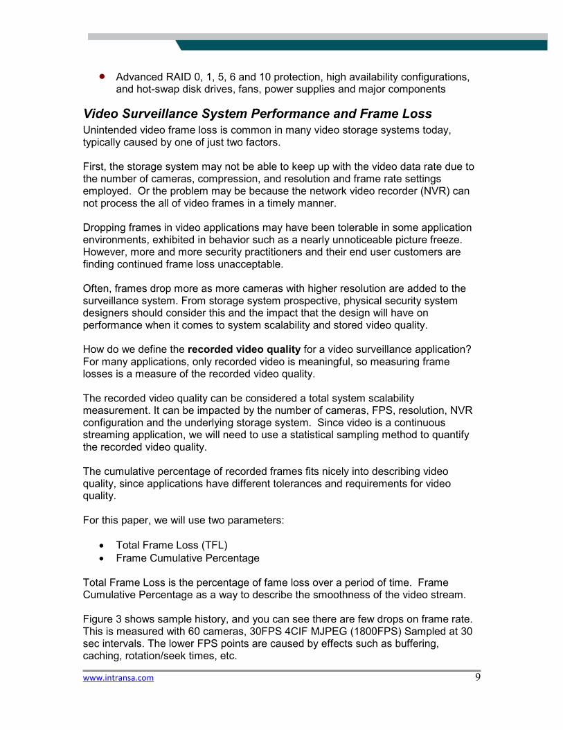
• Frame Cumulative Percentage Total Frame Loss is the percentage of fame loss over a period of time. Frame Cumulative Percentage as a way to describe the smoothness of the video stream. Figure 3 shows sample history, and you can see there are few drops on frame rate. This is measured with 60 cameras, 30FPS 4CIF MJPEG (1800FPS) Sampled at 30 sec intervals. The lower FPS points are caused by effects such as buffering, caching, rotation/seek times, etc.
www.intransa.com 10
Figure 3: Frame rate as recorded by storage system
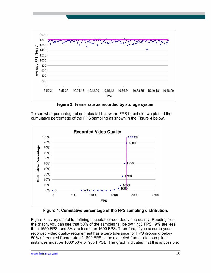
To see what percentage of samples fall below the FPS threshold, we plotted the cumulative percentage of the FPS sampling as shown in the Figure 4 below.
. Figure 4: Cumulative percentage of the FPS sampling distribution.
Figure 3 is very useful to defining acceptable recorded video quality. Reading from the graph, you can see that 50% of the samples fall below 1750 FPS. 9% are less than 1650 FPS, and 3% are less than 1600 FPS. Therefore, if you assume your recorded video quality requirement has a zero tolerance for FPS dropping below 50% of required frame rate (if 1800 FPS is the expected frame rate, sampling instances must be 1800*50% or 900 FPS). The graph indicates that this is possible.
0
200
400
600
800
1000
1200
1400
1600
1800
2000
9:50:24 9:57:36 10:04:48 10:12:00 10:19:12 10:26:24 10:33:36 10:40:48 10:48:00
Time
Avera
ge F
PS
[30sec]
Recorded Video Quality
0 70016001650
1700
1750
1800
1850
0%
10%
20%
30%
40%
50%
60%
70%
80%
90%
100%
0 500 1000 1500 2000 2500
FPS
Cum
ula
tive P
erc
enta
ge
www.intransa.com 11
If your requirement is that no more than 2% of samples have a frame loss exceeding 10% (1800*(1-10%) = 1620 FPS), the graph indicates this cannot be achieved with the current system.
Part Two: Test Configuration
System Setup and Configuration
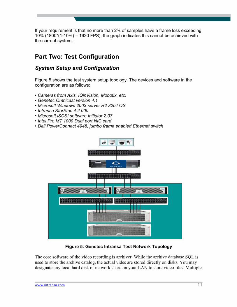
Figure 5 shows the test system setup topology. The devices and software in the configuration are as follows: • Cameras from Axis, IQinVision, Mobotix, etc. • Genetec Omnicast version 4.1 • Microsoft Windows 2003 server R2 32bit OS • Intransa StorStac 4.2.000 • Microsoft iSCSI software Initiator 2.07 • Intel Pro MT 1000 Dual port NIC card • Dell PowerConnect 4948, jumbo frame enabled Ethernet switch
Figure 5: Genetec Intransa Test Network Topology
The core software of the video recording is archiver. While the archive database SQL is
used to store the archive catalog, the actual vides are stored directly on disks. You may
designate any local hard disk or network share on your LAN to store video files. Multiple
www.intransa.com 12
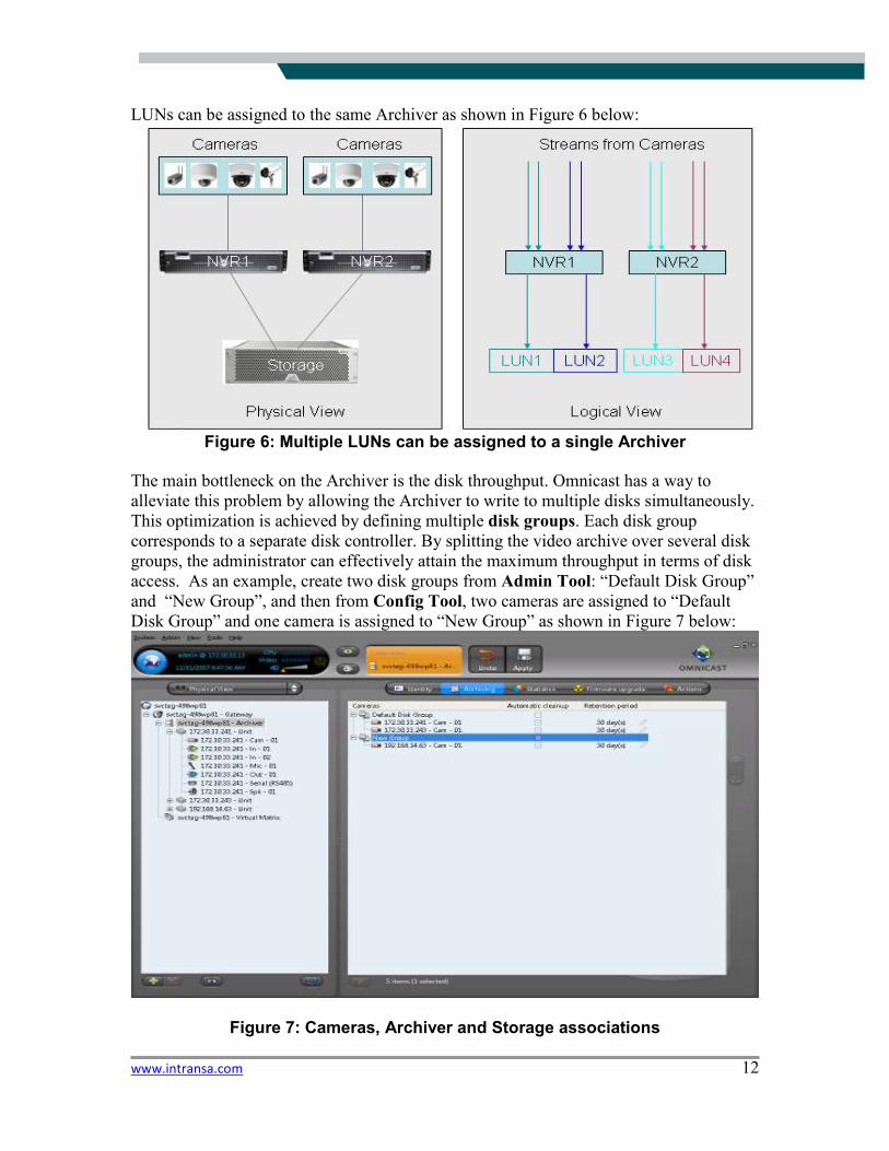
LUNs can be assigned to the same Archiver as shown in Figure 6 below:
Figure 6: Multiple LUNs can be assigned to a single Archiver
The main bottleneck on the Archiver is the disk throughput. Omnicast has a way to
alleviate this problem by allowing the Archiver to write to multiple disks simultaneously.
This optimization is achieved by defining multiple disk groups. Each disk group
corresponds to a separate disk controller. By splitting the video archive over several disk
groups, the administrator can effectively attain the maximum throughput in terms of disk
access. As an example, create two disk groups from Admin Tool: “Default Disk Group”
and “New Group”, and then from Config Tool, two cameras are assigned to “Default
Disk Group” and one camera is assigned to “New Group” as shown in Figure 7 below:
Figure 7: Cameras, Archiver and Storage associations
www.intransa.com 13
File layout and IO profile
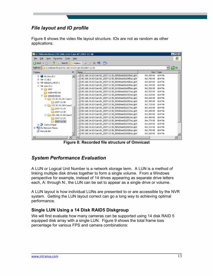
Figure 8 shows the video file layout structure. IOs are not as random as other applications.
Figure 8: Recorded file structure of Omnicast
System Performance Evaluation
A LUN or Logical Unit Number is a network storage term. A LUN is a method of linking multiple disk drives together to form a single volume. From a Windows perspective for example, instead of 14 drives appearing as separate drive letters each, A: through N:, the LUN can be set to appear as a single drive or volume. A LUN layout is how individual LUNs are presented to or are accessible by the NVR system. Getting the LUN layout correct can go a long way to achieving optimal performance.
Single LUN Using a 14 Disk RAID5 Diskgroup
We will first evaluate how many cameras can be supported using 14 disk RAID 5 equipped disk array with a single LUN. Figure 9 shows the total frame loss percentage for various FPS and camera combinations:
www.intransa.com 14
3040
5055
6064 10
2025
30
0
1
2
3
4
5
6
Frame Loss %
#CamerasFPS
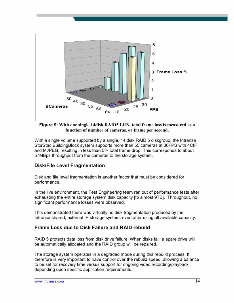
Figure 9: With one single 14disk RAID5 LUN, total frame loss is measured as a
function of number of cameras, or frame per second. With a single volume supported by a single, 14 disk RAID 5 diskgroup, the Intransa StorStac BuildingBlock system supports more than 55 cameras at 30FPS with 4CIF and MJPEG, resulting in less than 5% total frame drop. This corresponds to about 57MBps throughput from the cameras to the storage system.
Disk/File Level Fragmentation
Disk and file level fragmentation is another factor that must be considered for performance. In the live environment, the Test Engineering team ran out of performance tests after exhausting the entire storage system disk capacity [to almost 9TB]. Throughout, no significant performance losses were observed. This demonstrated there was virtually no disk fragmentation produced by the Intransa shared, external IP storage system, even after using all available capacity.
Frame Loss due to Disk Failure and RAID rebuild
RAID 5 protects data loss from disk drive failure. When disks fail, a spare drive will be automatically allocated and the RAID group will be repaired. The storage system operates in a degraded mode during this rebuild process. It therefore is very important to have control over the rebuild speed, allowing a balance to be set for recovery time versus support for ongoing video recording/playback, depending upon specific application requirements.

www.intransa.com 15
Not all storage systems are able to provide this rebuild speed control, although all Intransa StorStac systems do. That allows the RAID group to be rebuilt at the optimized speed, and avoid significant impact to video recording and frame rate.
Live Viewer and Archiver Player
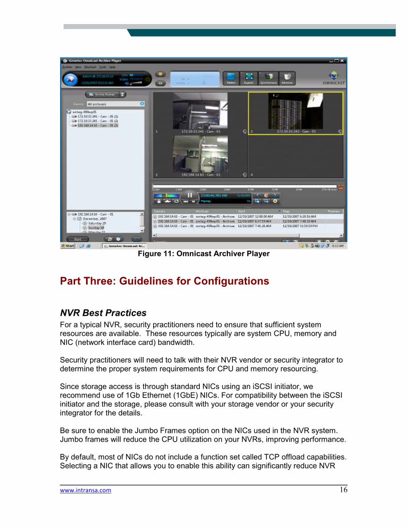
Both live videos as well as archived videos can be accessed from anywhere in the
network. Figure 10 and Figure 11 shows a screen capture from both live viewer and
archiver play.
Figure 10: Omnicast live viewer
www.intransa.com 16
Figure 11: Omnicast Archiver Player
Part Three: Guidelines for Configurations
NVR Best Practices
For a typical NVR, security practitioners need to ensure that sufficient system resources are available. These resources typically are system CPU, memory and NIC (network interface card) bandwidth. Security practitioners will need to talk with their NVR vendor or security integrator to determine the proper system requirements for CPU and memory resourcing. Since storage access is through standard NICs using an iSCSI initiator, we recommend use of 1Gb Ethernet (1GbE) NICs. For compatibility between the iSCSI initiator and the storage, please consult with your storage vendor or your security integrator for the details. Be sure to enable the Jumbo Frames option on the NICs used in the NVR system. Jumbo frames will reduce the CPU utilization on your NVRs, improving performance. By default, most of NICs do not include a function set called TCP offload capabilities. Selecting a NIC that allows you to enable this ability can significantly reduce NVR
www.intransa.com 17
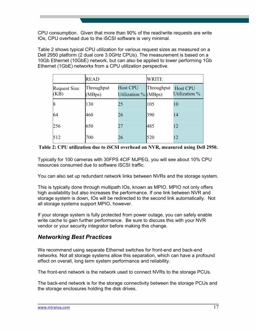
CPU consumption. Given that more than 90% of the read/write requests are write IOs, CPU overhead due to the iSCSI software is very minimal. Table 2 shows typical CPU utilization for various request sizes as measured on a Dell 2950 platform (2 dual core 3.0GHz CPUs). The measurement is based on a 10Gb Ethernet (10GbE) network, but can also be applied to lower performing 1Gb Ethernet (1GbE) networks from a CPU utilization perspective.
READ WRITE
Request Size (KB)
Throughput
(MBps)
Host CPU
Utilization %
Throughput
(MBps)
Host CPU Utilization %
8 130 25 105 10
64 460 26 390 14
256 650 27 485 12
512 700 26 520 12
Table 2: CPU utilization due to iSCSI overhead on NVR, measured using Dell 2950.
Typically for 100 cameras with 30FPS 4CIF MJPEG, you will see about 10% CPU resources consumed due to software iSCSI traffic. You can also set up redundant network links between NVRs and the storage system. This is typically done through multipath IOs, known as MPIO. MPIO not only offers high availability but also increases the performance. If one link between NVR and storage system is down, IOs will be redirected to the second link automatically. Not all storage systems support MPIO, however. If your storage system is fully protected from power outage, you can safely enable write cache to gain further performance. Be sure to discuss this with your NVR vendor or your security integrator before making this change.
Networking Best Practices
We recommend using separate Ethernet switches for front-end and back-end networks. Not all storage systems allow this separation, which can have a profound effect on overall, long term system performance and reliability. The front-end network is the network used to connect NVRs to the storage PCUs. The back-end network is for the storage connectivity between the storage PCUs and the storage enclosures holding the disk drives.

www.intransa.com 18
Jumbo Frames Enable Jumbo Frames on the NVR, storage PCU, switches, and storage enclosures. On an Intransa PCU, Jumbo Frames are enabled as: StorStac> interface display Name Controller State Alerts IPAddress NetMask MTU ---------------------------------------------------------------------- eth1 c0015C5F525B4 Healthy 0 172.30.33.232 255.255.255.0 1500 eth1:0 c0015C5F525B4 Healthy 0 172.30.33.230 255.255.255.0 1500 team1 c0015C5F525B4 Healthy 0 192.168.0.50 255.255.255.0 9000 team1:0 c0015C5F525B4 Healthy 0 192.168.0.230 255.255.255.0 9000 eth2 c0015C5F525B4 Healthy 0 192.168.0.50 255.255.255.0 9000 eth5 c0015C5F525B4 Healthy 0 192.168.0.50 255.255.255.0 9000 eth3 c0015C5F525B4 Healthy 0 10.0.2.1 255.255.0.0 9000 eth4 c0015C5F525B4 Healthy 0 10.0.2.2 255.255.0.0 9000 Response: Successful StorStac> Enable Flow Control on the Switch You can verify flow control has been correct set from the Intransa storage PCU: StorStac> debug shell root@controller:/opt/internal:Debug> ethtool -a eth2 Pause parameters for eth2: Autonegotiate: on RX: on TX: on root@controller:/opt/internal:Debug> ethtool -a eth3 Pause parameters for eth3: Autonegotiate: on RX: on TX: on root@controller:/opt/internal:Debug> ethtool -a eth4 Pause parameters for eth4: Autonegotiate: on RX: on TX: on
Storage Best Practices
GPT and Alignment Video typically consumes many TB of storage; you should use a GPT (GUID or globally unique identifier partition table) partition.

www.intransa.com 19
GPT partitions are useful instead of using MBR (Master Boot Records) to enable more than 2TB volume support. When you first initialize the disk, you will see disk [default NBR format]: Perform an alignment before you create the NTFS, as this will increase your performance:
C:\>diskpart
Microsoft DiskPart version 5.2.3790.1830
Copyright (C) 1999-2001 Microsoft Corporation.
On computer: MKT-10G-S1
DISKPART> select disk 3
Disk 1 is now the selected disk.
DISKPART> create partition primary align=64
DiskPart succeeded in creating the specified partition.
DISKPART> exit
Leaving DiskPart...
Align the storage system with NTFS. Here is an easy way to increase disk performance
using the Command Line Interface (CLI) commands below:
C:\>diskpart
Microsoft DiskPart version 5.2.3790.1830
Copyright (C) 1999-2001 Microsoft Corporation.
On computer: MKT-10G-S1
DISKPART> select disk 3
Disk 1 is now the selected disk.
DISKPART> create partition primary align=64
DiskPart succeeded in creating the specified partition.
DISKPART> exit
Leaving DiskPart...
Next, format it using 64KB allocation unit size.
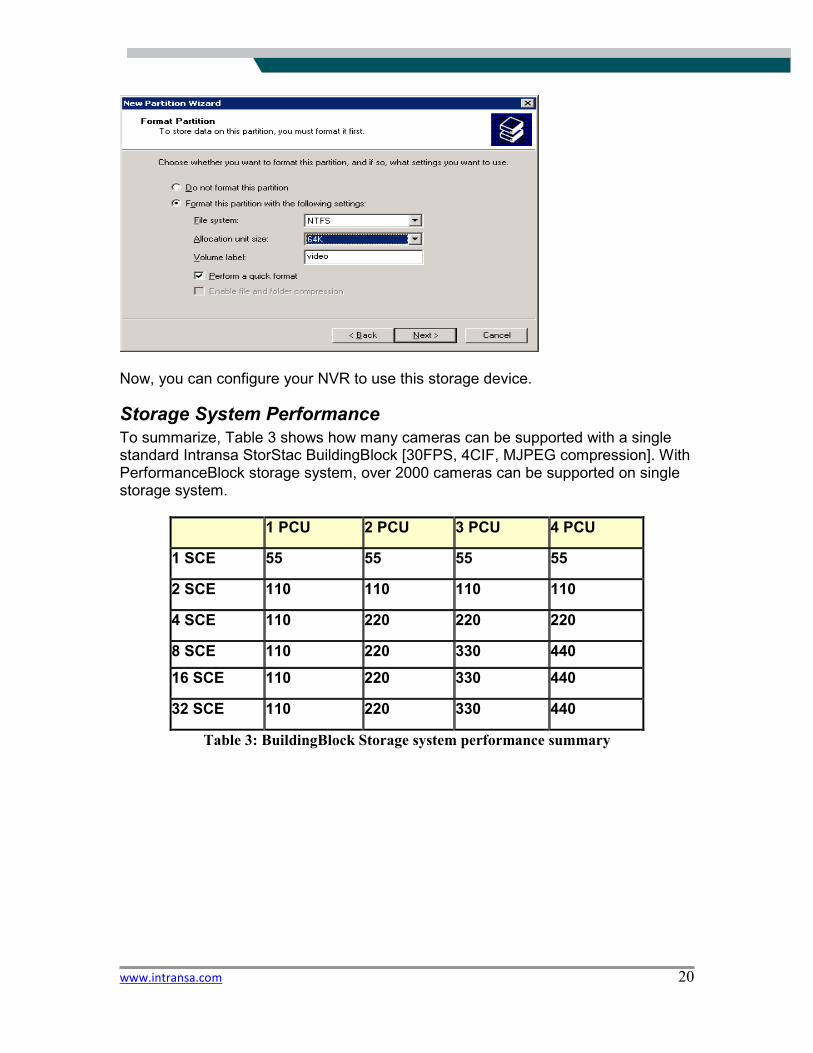
www.intransa.com 20
Now, you can configure your NVR to use this storage device.
Storage System Performance
To summarize, Table 3 shows how many cameras can be supported with a single standard Intransa StorStac BuildingBlock [30FPS, 4CIF, MJPEG compression]. With PerformanceBlock storage system, over 2000 cameras can be supported on single storage system.
1 PCU 2 PCU 3 PCU 4 PCU
1 SCE 55 55 55 55
2 SCE 110 110 110 110
4 SCE 110 220 220 220
8 SCE 110 220 330 440
16 SCE 110 220 330 440
32 SCE 110 220 330 440
Table 3: BuildingBlock Storage system performance summary
www.intransa.com 21
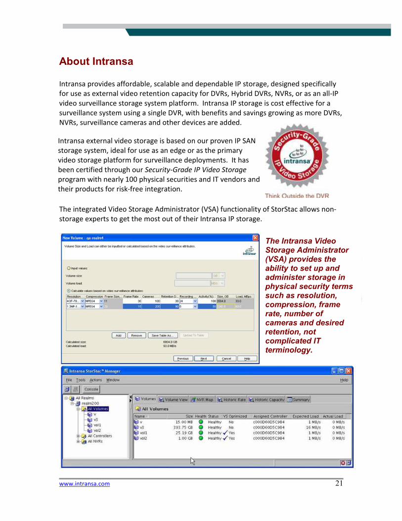
About Intransa
Intransa provides affordable, scalable and dependable IP storage, designed specifically
for use as external video retention capacity for DVRs, Hybrid DVRs, NVRs, or as an all-IP
video surveillance storage system platform. Intransa IP storage is cost effective for a
surveillance system using a single DVR, with benefits and savings growing as more DVRs,
NVRs, surveillance cameras and other devices are added.
The integrated Video Storage Administrator (VSA) functionality of StorStac allows non-
storage experts to get the most out of their Intransa IP storage.
Intransa external video storage is based on our proven IP SAN
storage system, ideal for use as an edge or as the primary
video storage platform for surveillance deployments. It has
been certified through our Security-Grade IP Video Storage
program with nearly 100 physical securities and IT vendors and
their products for risk-free integration.
The Intransa Video Storage Administrator (VSA) provides the ability to set up and administer storage in physical security terms such as resolution, compression, frame rate, number of cameras and desired retention, not complicated IT terminology.
www.intransa.com 22
Unlike captive, fixed storage in DVRs or standard IT workload storage sometimes found
with NVR systems, Intransa external IP storage is optimized for video workloads. This
video optimization also eliminates performance problems related to disk fragmentation
found in general purpose IT storage, and allows higher utilization that can lessen the
total amount of storage required.
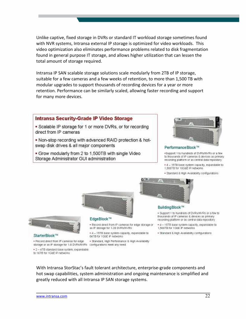
Intransa IP SAN scalable storage solutions scale modularly from 2TB of IP storage,
suitable for a few cameras and a few weeks of retention, to more than 1,500 TB with
modular upgrades to support thousands of recording devices for a year or more
retention. Performance can be similarly scaled, allowing faster recording and support
for many more devices.
With Intransa StorStac’s fault tolerant architecture, enterprise-grade components and
hot swap capabilities, system administration and ongoing maintenance is simplified and
greatly reduced with all Intransa IP SAN storage systems.
www.intransa.com 23
Intransa IP storage is also proven for standard IT applications like storage consolidation
and virtualization for “Green IT” needs, with support for both 1 and 10GbE IP interfaces.
Some users chose to run IT and physical security applications on the same Intransa
system, as needed. Advanced Intransa-developed features are also included for IT
storage administrators. These include Intransa DynaStac Thin Provisioning, StorAR
Asynchronous Replication, RAID 0, 1, 5, 6, and 10 support, StorCluster N+1 Clustering
and Failover, StorStac Snapshot, Global Sparing, Dynamic Load Balancing, Non-
disruptive Upgrades, call home support, and the powerful StorManager graphical user
interface (GUI) and integrated command line interface (CLI).
Intransa believes in the power of partnership and alliances, and has funded the StorAlliance
Technology Lab to ensure that the promise of IP is delivered in real world solutions. The lab
certifies IT products through the Intransa 10GbE IP SAN Certified program and the Security-
Grade IP Video Storage Certified program for physical security.
Through the StorAlliance program, and other real-world test environments such as the GSO
2010 (www.gsoevents.com) conference series where security practitioner participants get to
perform hands on testing with multiple IP systems from a dozen or more vendors all using
Intransa IP storage, external IP storage upgrades are tested in real world conditions before
reaching customers.
Intransa IP storage is multi-function in nature, unlike the single purpose storage found in
DVRs and NVRs. Physical security applications like life safety, access control, physical
security information systems and IP devices ranging from surveillance cameras through
to card readers, slot machines and retail systems can all benefit from the storage system.
IT vendors certified include those offering operating systems, email, relational
databases, ILM, CDP, HSM, VTL, backup and recovery, data warehousing, data mining,
clustered file systems, network attached storage, and server and storage consolidation.
Participants include Microsoft, with the first IP storage to be certified with 10GbE
interfaces supporting Microsoft Exchange 2007, and VMware ESX virtualization.
www.intransa.com 24
Only vendor products that have been tested in a similar manner can be considered as low risk
for physical security applications, in addition to demonstrating real-world customer
deployments.
Intransa believes in standards for the good of the industry and our customers. As such we also
are members and supporters of key industry associations, including the Security Industry
Association (SIA), the American Correctional Association (ACA), the Storage Networking Industry
Association (SNIA) and its Green Storage Initiative, and the Green Grid for green IT. Intransa
employees are also members and participants in important professional associations, including
ASIS International and its Physical Security Council.
Intransa Security-Grade IP Video Storage is available from Intransa StorPartner
integrators and dealers worldwide. To learn more, contact Intransa or an Intransa
StorPartner.
Intransa, Inc.
Corporate Headquarters
2870 Zanker Road, Suite 200, San Jose, CA 95134-2114
866 446 7726 or 407 678 8600 / www.intransa.com / [email protected]
© 2008 Intransa, Inc. All rights reserved.