VIDEO OR AUDIO ELVOX 2-WIRE ENTRANCE PANELS … 1.pdf · VIDEO OR AUDIO ELVOX 2-WIRE ENTRANCE...
56
Cod. S6I.12F.50E RL.01 4/2009 GB VIDEO OR AUDIO ELVOX 2-WIRE ENTRANCE PANELS WITH TRADITIONAL PUSH-BUTTONS Product is according to EC Directive 2004/108/CE and following norms. (V4 Software version) 3 2 1 START SI / YES STOP FINE END 1 PREC. PREV 2 SUCC. NEXT 3 OK 3 2 1 1 PREC. PREV 2 SUCC. NEXT 3 OK PRI PROTECTION by PTC 230V ~ 50-60Hz 60VA max Art. 6922 ITALY
Transcript of VIDEO OR AUDIO ELVOX 2-WIRE ENTRANCE PANELS … 1.pdf · VIDEO OR AUDIO ELVOX 2-WIRE ENTRANCE...
Cod. S6I.12F.50E RL.01 4/2009
GB
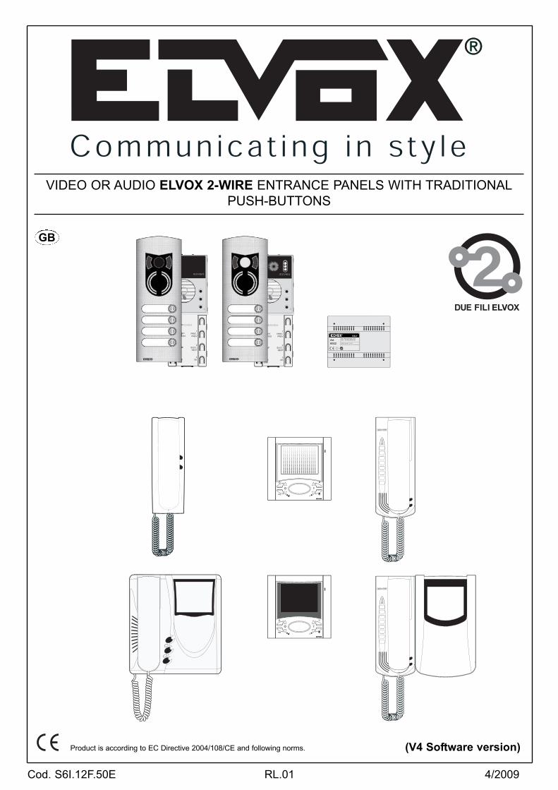
VIDEO OR AUDIO ELVOX 2-WIRE ENTRANCE PANELS WITH TRADITIONAL
PUSH-BUTTONS
Product is according to EC Directive 2004/108/CE and following norms. (V4 Software version)
3
2
1
STARTSI / YES
STOP
FINEEND
1PREC.PREV
2SUCC.NEXT
3OK
3
2
1
1PREC.PREV
2SUCC.NEXT
3OK
R
PRI PROTECTION by PTC
1/2, B1/B2: 28Vc.c./D.C. 1,3A - INT
0/28: 28Vc.c./D.C. (0,2A - INT AUX / 0,1A - CONTAUX)
230V ~ 50-60Hz 60VA maxArt.6922
ITALY
2
3
2
1
4STARTSI / YES
5STOPNO
6FINEEND
1PREC.PREV
2SUCC.NEXT
3OK
PRG
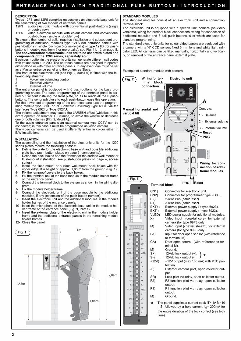
CN1) Connector for electronic unit.
CN2) Connector for programmer type 950C.
B2) 2-wire Bus (cable riser).
B1) 2-wire Bus (cable riser).
EXT+) External power supply (+ type 6923).
EXT-) External power supply (- type 6923).
VLED) LED power supply for additional modules.
X) Video input (coaxial core), for external
camera (for type 89F8 only).
M) Video input (coaxial sheath), for external
camera (for type 89F8 only).
PA) Input for door open sensor (with reference
to terminal M).
CA) Door open control (with reference to ter-
minal M).
M) Ground.
S+) 12Vdc lock output (+).
S-) 12Vdc lock output (-).
+12V) +12V output (max 100 mA) with PTC pro-
tection.
-L) External camera pilot, open collector out-
put.
SR) Lock pilot via relay, open collector output.
F2) F2 function pilot via relay, open collector
output.
F1) F1 function pilot via relay, open collector
output.
M) Ground.
E N T R A N C E P A N E L W I T H T R A D I T I O N A L P U S H - B U T T O N S : I N T R O D U C T I O N
B2
B1
EXT+
EXT-
VLED
M
PA
CA
M
S+
S-
+12V
-L
SR
F2
F1
M
X
B2
B1
EXT+
EXT-
VLED
M
PA
CA
M
S+
S-
+12V
-L
SR
F2
F1
M
X
CN
2C
N1
CS
2411
250
105
Wiring for ter-
minal block
connection
Wiring for con-
nection of addi-
tional modules
Controls:
1 - Balance
2 - External volume
3 - Internal volume
Manual horizontal and
vertical tilt
Fig. 3
Reset
) *
DESCRIPTION Types 12F3 and 12F5 comprise respectively an electronic base unit forthe assembling of two models of entrance panels.12F3 audio electronic module with conventional push-buttons (single
or double row) 12F5 video electronic module with colour camera and conventional
push-buttons (single or double row) To expand the number of calls, requires installation and subsequent pro-gramming of additional modules type 12TS (for entrance panels withpush-buttons in single row, from 5 or more calls) or type 12TD (for push-buttons in double row, from 9 or more calls), see Fig. 11, 12 on page 8.The abovementioned electronic units are to be used with plates andcomponents of the 1200 series, separately sold.Each push-button in the electronic units can generate different call codeswith values from 1 to 200. The entrance panels are designed to operateeither alone or with other entrance panels. In any event one must be setas a Master entrance panel and the others as Slave. The front of the electronic unit (see Fig. 2, detail A) is fitted with the fol-lowing adjustments:1 Voice line balancing control2 External volume3 Internal volumeThe entrance panel is equipped with 6 push-buttons for the base pro-gramming phase. The base programming of the entrance panel is car-ried out without installing the front plate, so as to reach all the 6 push-buttons. The serigraph close to each push-button ease this operation. For the advanced programming of the entrance panel use the program-ming module type 950C or PC Software SaveProg Type 69CD via theinterfaces Type 692I or Type 692I/U.The volume adjustment may cause the LARSEN effect (whistle); in thisevent operate on trimmer 1 (Balance) to avoid the whistle or decreaseone or both volumes (Fig. 2, detail A).To the audio entrance panels an external camera type CCTV can beconnected; in this case it must be programmed as video camera.The video cameras can be used indifferently either in colour either inB/W installations
INSTALLATIONThe assembling and the installation of the electronic units for the 1200series plates require the following phases:1- Define the plate for the electronic base unit and possible additional
plate (see push-button plates on page 3, components).2- Define the back boxes and the frames for the surface wall-mount or
flush-mount installation (see push-button plates on page 4, acces-sories).
3- Install the flush-mount or surface wall-mount back boxes with theupper edge at a height of approx. 1,65 m from the ground (Fig. 1).
4- Fix the rainproof covers to the back boxes.5- Fix the terminal box of the base module to the module holder frame
of the entrance panel.6- Connect the terminal block to the system as shown in the wiring dia-
gram.7- Fix the module holder frame.8- Connect the electronic unit of the base module to the additional
modules, if any (extension of the push-button number).9- Insert the electronic unit and the additional modules in the module
holder frames of the entrance panels.10- Insert the microphone of the electronic base unit in the module hol-
der frame of the entrance panel (Fig. 9, Part 1).11- Insert the external plate of the electronic unit in the module holder
frame and the additional entrance panels in the remaining moduleholder frames.
12- Close the panel.
Fig. 1
Electronic unitFig. 2
A
Terminal block
* The panel supplies a current peak IT> 1A for 10
mS, followed by a hold current IM= 200mA for
the entire duration of the lock control (see lock
time).
STANDARD MODULES
The standard modules consist of: an electronic unit and a connection
terminal block.
The electronic unit is equipped with a speech unit, camera (on video
versions), wiring for terminal block connections, wiring for connection of
additional modules and 8 call push-buttons, 6 of which are used for
standard programming.
The standard electronic units for colour video panels are equipped with
a camera with a ¼" CCD sensor, fixed 3 mm lens and white light indi-
cator LED. All cameras can be tilted manually, horizontally and vertical-
ly, on removal of the entrance panel external plate.
Example of standard module with camera.
1,65m
2,04m
1,04m
1m
Reset
PRG
3
E N T R A N C E P A N E L W I T H T R A D I T I O N A L P U S H - B U T T O N S : I N T R O D U C T I O N
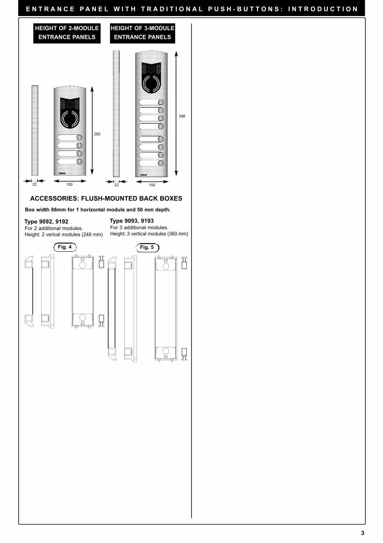
Fig. 4 Fig. 5
HEIGHT OF 2-MODULE
ENTRANCE PANELS
HEIGHT OF 3-MODULE
ENTRANCE PANELS
Box width 88mm for 1 horizontal module and 50 mm depth.
Type 9092, 9192For 2 additional modules.
Height: 2 verical modules (248 mm)
Type 9093, 9193For 3 additional modules.
Height: 3 vertical modules (360 mm)
ACCESSORIES: FLUSH-MOUNTED BACK BOXES
396
100
282
2210022
4
E N T R A N C E P A N E L W I T H T R A D I T I O N A L P U S H - B U T T O N S : I N T R O D U C T I O N
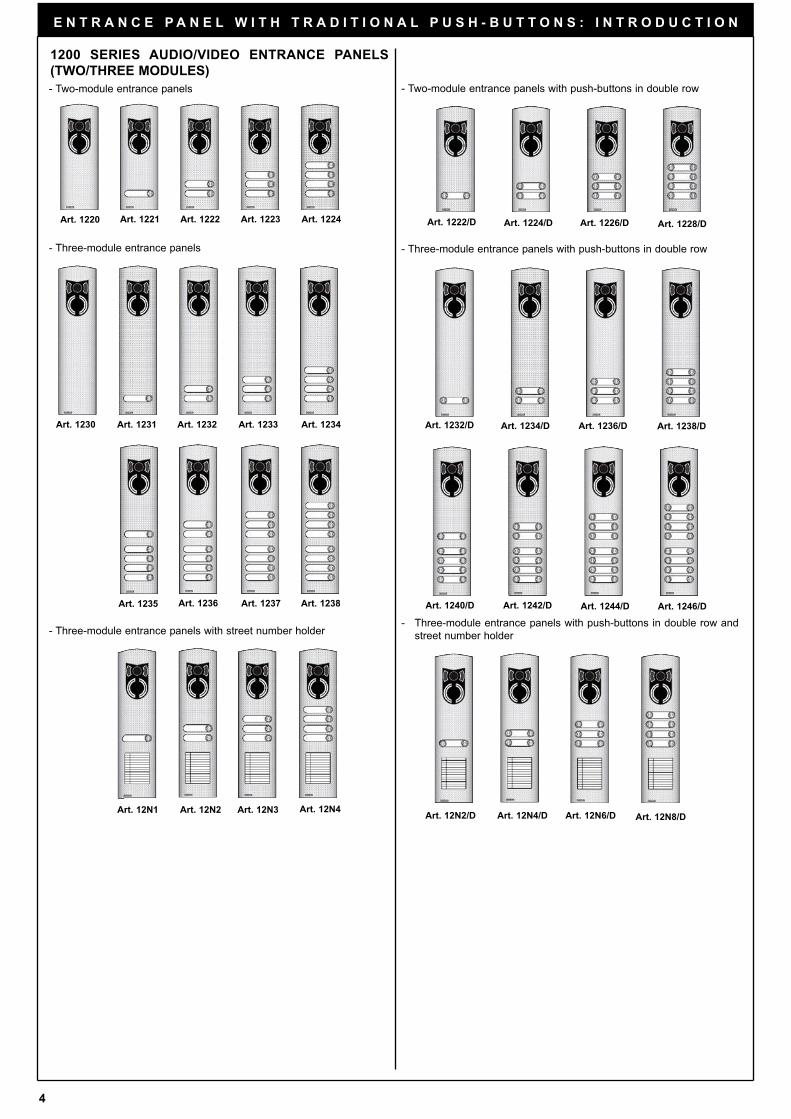
Art. 1222/D Art. 1224/D Art. 1226/D Art. 1228/D
Art. 1232/D Art. 1234/D Art. 1236/D
Art. 1240/D Art. 1242/D Art. 1244/D Art. 1246/D
Art. 12N2/D
Art. 1238/D
Art. 12N4/D Art. 12N6/D Art. 12N8/DArt. 12N1 Art. 12N2 Art. 12N3
Art. 1230 Art. 1231 Art. 1232 Art. 1233 Art. 1234
Art. 1235 Art. 1236 Art. 1237
Art. 1220 Art. 1221 Art. 1222 Art. 1223
Art. 12N4
Art. 1224
Art. 1238
1200 SERIES AUDIO/VIDEO ENTRANCE PANELS
(TWO/THREE MODULES)
- Two-module entrance panels with push-buttons in double row
- Three-module entrance panels with push-buttons in double row
- Three-module entrance panels with push-buttons in double row and
street number holder
- Two-module entrance panels
- Three-module entrance panels
- Three-module entrance panels with street number holder
5
E N T R A N C E P A N E L W I T H T R A D I T I O N A L P U S H - B U T T O N S : I N T R O D U C T I O N
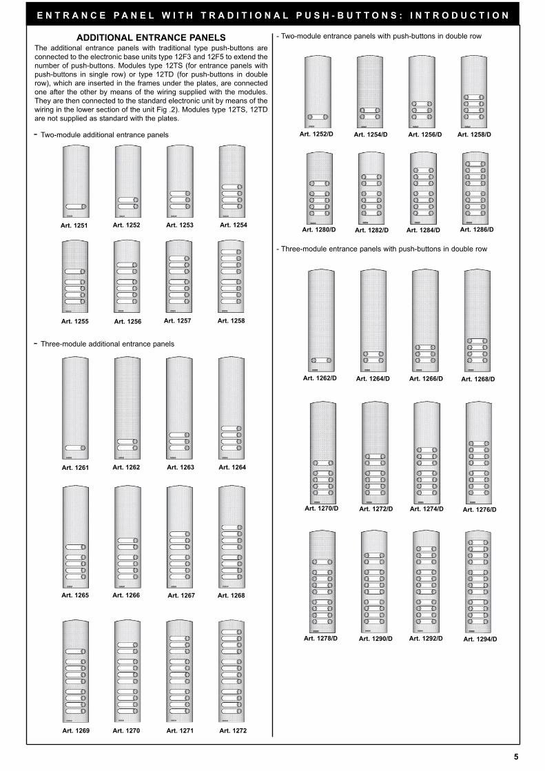
ADDITIONAL ENTRANCE PANELSThe additional entrance panels with traditional type push-buttons are
connected to the electronic base units type 12F3 and 12F5 to extend the
number of push-buttons. Modules type 12TS (for entrance panels with
push-buttons in single row) or type 12TD (for push-buttons in double
row), which are inserted in the frames under the plates, are connected
one after the other by means of the wiring supplied with the modules.
They are then connected to the standard electronic unit by means of the
wiring in the lower section of the unit Fig .2). Modules type 12TS, 12TD
are not supplied as standard with the plates.
Art. 1252/D Art. 1254/D Art. 1256/D Art. 1258/D
Art. 1280/D Art. 1282/D Art. 1284/D Art. 1286/D
Art. 1262/D Art. 1264/D Art. 1266/D Art. 1268/D
Art. 1270/D Art. 1272/D Art. 1274/D Art. 1276/D
Art. 1278/D Art. 1290/D Art. 1292/D Art. 1294/D
Art. 1261 Art. 1262 Art. 1263 Art. 1264
Art. 1265 Art. 1266 Art. 1267 Art. 1268
Art. 1269 Art. 1270 Art. 1271 Art. 1272
Art. 1251 Art. 1252 Art. 1253 Art. 1254
Art. 1255 Art. 1256 Art. 1257 Art. 1258
- Two-module additional entrance panels
- Three-module additional entrance panels
- Three-module entrance panels with push-buttons in double row
- Two-module entrance panels with push-buttons in double row
6
E N T R A N C E P A N E L W I T H T R A D I T I O N A L P U S H - B U T T O N S : I N S T A L L A T I O N
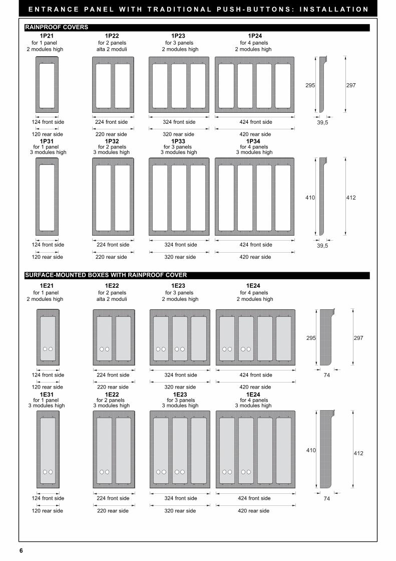
1P21 1P22 1P23 1P24for 1 panel for 2 panels for 3 panels for 4 panels
2 modules high alta 2 moduli 2 modules high 2 modules high
RAINPROOF COVERS
1E21 1E22 1E23 1E24for 1 panel for 2 panels for 3 panels for 4 panels
2 modules high alta 2 moduli 2 modules high 2 modules high
SURFACE-MOUNTED BOXES WITH RAINPROOF COVER
297
39,5
39,5
412
295
410
74
74
297
412
295
410
124 front side 224 front side 324 front side 424 front side
120 rear side 220 rear side 320 rear side 420 rear side
124 front side 224 front side 324 front side 424 front side
120 rear side 220 rear side 320 rear side 420 rear side
124 front side 224 front side 324 front side 424 front side
120 rear side 220 rear side 320 rear side 420 rear side
124 front side 224 front side 324 front side 424 front side
120 rear side 220 rear side 320 rear side 420 rear side
1E31 1E22 1E23 1E24for 1 panel for 2 panels for 3 panels for 4 panels
3 modules high 3 modules high 3 modules high 3 modules high
1P31 1P32 1P33 1P34for 1 panel for 2 panels for 3 panels for 4 panels
3 modules high 3 modules high 3 modules high 3 modules high
7
E N T R A N C E P A N E L W I T H T R A D I T I O N A L P U S H - B U T T O N S : I N S T A L L A T I O N
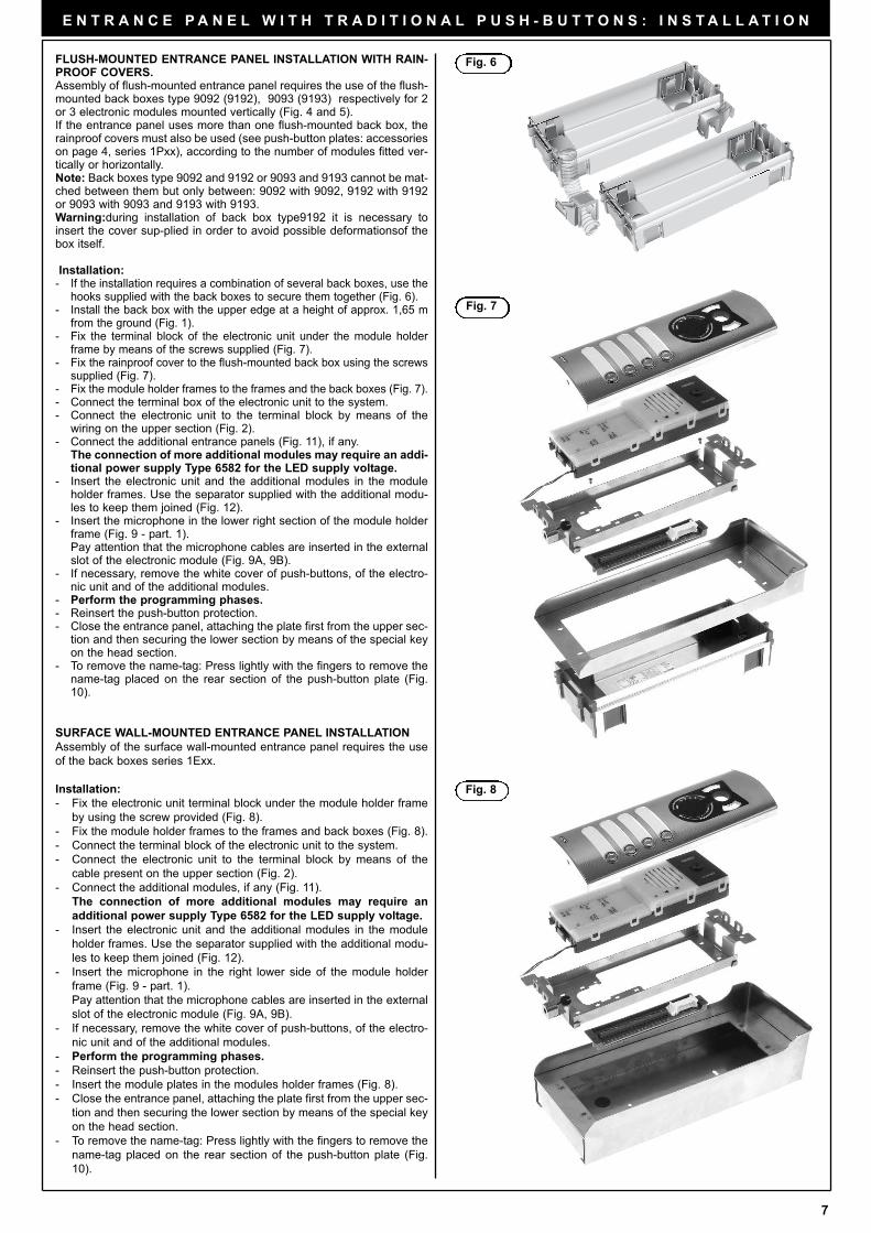
FLUSH-MOUNTED ENTRANCE PANEL INSTALLATION WITH RAIN-PROOF COVERS. Assembly of flush-mounted entrance panel requires the use of the flush-mounted back boxes type 9092 (9192), 9093 (9193) respectively for 2or 3 electronic modules mounted vertically (Fig. 4 and 5).If the entrance panel uses more than one flush-mounted back box, therainproof covers must also be used (see push-button plates: accessorieson page 4, series 1Pxx), according to the number of modules fitted ver-tically or horizontally.Note: Back boxes type 9092 and 9192 or 9093 and 9193 cannot be mat-ched between them but only between: 9092 with 9092, 9192 with 9192or 9093 with 9093 and 9193 with 9193.Warning:during installation of back box type9192 it is necessary toinsert the cover sup-plied in order to avoid possible deformationsof thebox itself.
Installation:- If the installation requires a combination of several back boxes, use the
hooks supplied with the back boxes to secure them together (Fig. 6).- Install the back box with the upper edge at a height of approx. 1,65 m
from the ground (Fig. 1).- Fix the terminal block of the electronic unit under the module holder
frame by means of the screws supplied (Fig. 7).- Fix the rainproof cover to the flush-mounted back box using the screws
supplied (Fig. 7).- Fix the module holder frames to the frames and the back boxes (Fig. 7).- Connect the terminal box of the electronic unit to the system.- Connect the electronic unit to the terminal block by means of the
wiring on the upper section (Fig. 2).- Connect the additional entrance panels (Fig. 11), if any.
The connection of more additional modules may require an addi-tional power supply Type 6582 for the LED supply voltage.
- Insert the electronic unit and the additional modules in the moduleholder frames. Use the separator supplied with the additional modu-les to keep them joined (Fig. 12).
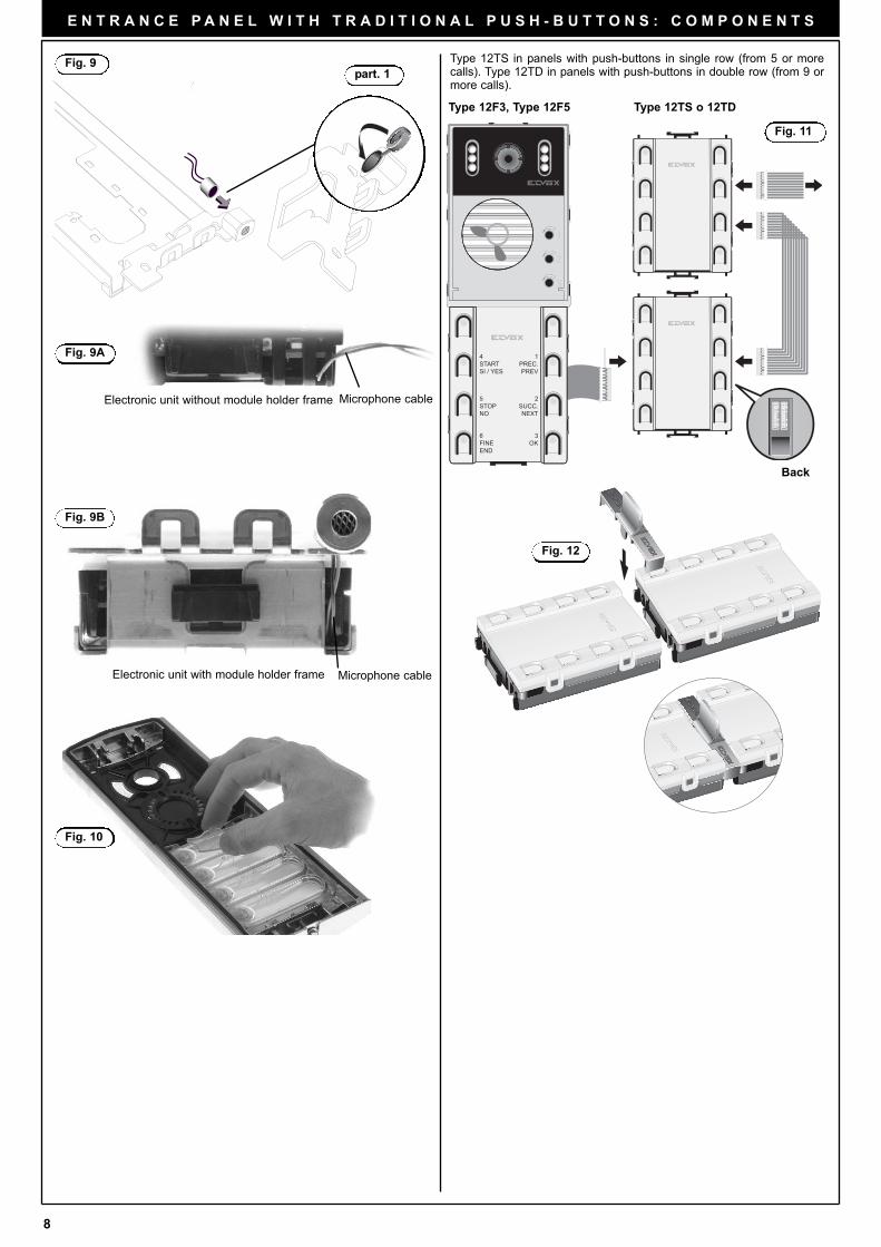
- Insert the microphone in the lower right section of the module holderframe (Fig. 9 - part. 1). Pay attention that the microphone cables are inserted in the externalslot of the electronic module (Fig. 9A, 9B).
- If necessary, remove the white cover of push-buttons, of the electro-nic unit and of the additional modules.
- Perform the programming phases.- Reinsert the push-button protection. - Close the entrance panel, attaching the plate first from the upper sec-
tion and then securing the lower section by means of the special keyon the head section.
- To remove the name-tag: Press lightly with the fingers to remove thename-tag placed on the rear section of the push-button plate (Fig.10).
SURFACE WALL-MOUNTED ENTRANCE PANEL INSTALLATION
Assembly of the surface wall-mounted entrance panel requires the use
of the back boxes series 1Exx.
Installation:
- Fix the electronic unit terminal block under the module holder frame
by using the screw provided (Fig. 8).
- Fix the module holder frames to the frames and back boxes (Fig. 8).
- Connect the terminal block of the electronic unit to the system.
- Connect the electronic unit to the terminal block by means of the
cable present on the upper section (Fig. 2).
- Connect the additional modules, if any (Fig. 11).
The connection of more additional modules may require an
additional power supply Type 6582 for the LED supply voltage.
- Insert the electronic unit and the additional modules in the module
holder frames. Use the separator supplied with the additional modu-
les to keep them joined (Fig. 12).
- Insert the microphone in the right lower side of the module holder
frame (Fig. 9 - part. 1).
Pay attention that the microphone cables are inserted in the external
slot of the electronic module (Fig. 9A, 9B).
- If necessary, remove the white cover of push-buttons, of the electro-
nic unit and of the additional modules.
- Perform the programming phases.
- Reinsert the push-button protection.
- Insert the module plates in the modules holder frames (Fig. 8).
- Close the entrance panel, attaching the plate first from the upper sec-
tion and then securing the lower section by means of the special key
on the head section.
- To remove the name-tag: Press lightly with the fingers to remove the
name-tag placed on the rear section of the push-button plate (Fig.
10).
Fig. 6
Fig. 7
Fig. 8
8
E N T R A N C E P A N E L W I T H T R A D I T I O N A L P U S H - B U T T O N S : C O M P O N E N T S
Fig. 11
Back
Fig. 12
Type 12F3, Type 12F5 Type 12TS o 12TD
Type 12TS in panels with push-buttons in single row (from 5 or morecalls). Type 12TD in panels with push-buttons in double row (from 9 ormore calls).
Fig. 9part. 1
Fig. 10
Fig. 9A
Fig. 9B
Microphone cable
Electronic unit with module holder frame
Electronic unit without module holder frame
Microphone cable
3
2
1
4STARTSI / YES
5STOPNO
6FINEEND
1PREC.PREV
2SUCC.NEXT
3OK
9
E N T R A N C E P A N E L W I T H T R A D I T I O N A L P U S H - B U T T O N S : P R O G R A M M I N G
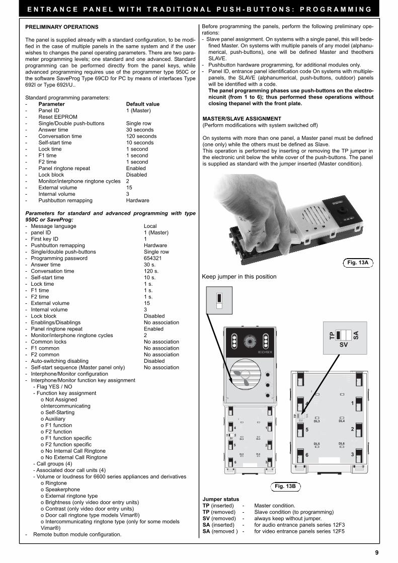
MASTER/SLAVE ASSIGNMENT
(Perform modifications with system switched off)
On systems with more than one panel, a Master panel must be defined
(one only) while the others must be defined as Slave.
This operation is performed by inserting or removing the TP jumper in
the electronic unit below the white cover of the push-buttons. The panel
is supplied as standard with the jumper inserted (Master condition).
Jumper status
TP (inserted) - Master condition.
TP (removed) - Slave condition (to programming)
SV (removed) - always keep without jumper.
SA (inserted) - for audio entrance panels series 12F3
SA (removed ) - for video entrance panels series 12F5
Keep jumper in this position
Fig. 13A
PRELIMINARY OPERATIONS
The panel is supplied already with a standard configuration, to be modi-
fied in the case of multiple panels in the same system and if the user
wishes to changes the panel operating parameters. There are two para-
meter programming levels; one standard and one advanced. Standard
programming can be performed directly from the panel keys, while
advanced programming requires use of the programmer type 950C or
the software SaveProg Type 69CD for PC by means of interfaces Type
692I or Type 692I/U..
Standard programming parameters:
- Parameter Default value
- Panel ID 1 (Master)
- Reset EEPROM
- Single/Double push-buttons Single row
- Answer time 30 seconds
- Conversation time 120 seconds
- Self-start time 10 seconds
- Lock time 1 second
- F1 time 1 second
- F2 time 1 second
- Panel ringtone repeat Enabled
- Lock block Disabled
- Monitor/interphone ringtone cycles 2
- External volume 15
- Internal volume 3
- Pushbutton remapping Hardware
Parameters for standard and advanced programming with type950C or SaveProg:- Message language Local
- panel ID 1 (Master)
- First key ID 1
- Pushbutton remapping Hardware
- Single/double push-buttons Single row
- Programming password 654321
- Answer time 30 s.
- Conversation time 120 s.
- Self-start time 10 s.
- Lock time 1 s.
- F1 time 1 s.
- F2 time 1 s.
- External volume 15
- Internal volume 3
- Lock block Disabled
- Enablings/Disablings No association
- Panel ringtone repeat Enabled
- Monitor/interphone ringtone cycles 2
- Common locks No association
- F1 common No association
- F2 common No association
- Auto-switching disabling Disabled
- Self-start sequence (Master panel only) No association
- Interphone/Monitor configuration
- Interphone/Monitor function key assignment
- Flag YES / NO
- Function key assignment
o Not Assigned
oIntercommunicating
o Self-Starting
o Auxiliary
o F1 function
o F2 function
o F1 function specific
o F2 function specific
o No Internal Call Ringtone
o No External Call Ringtone
- Call groups (4)
- Associated door call units (4)
- Volume or loudness for 6600 series appliances and derivatives
o Ringtone
o Speakerphone
o External ringtone type
o Brightness (only video door entry units)
o Contrast (only video door entry units)
o Door call ringtone type models Vimar®)
o Intercommunicating ringtone type (only for some models
Vimar®)
- Remote button module configuration.
Before programming the panels, perform the following preliminary ope-
rations:
- Slave panel assignment. On systems with a single panel, this will bede-
fined Master. On systems with multiple panels of any model (alphanu-
merical, push-buttons), one will be defined Master and theothers
SLAVE.
- Pushbutton hardware programming, for additional modules only.
- Panel ID, entrance panel identification code On systems with multiple-
panels, the SLAVE (alphanumerical, push-buttons, outdoor) panels
will be identified with a code.
The panel programming phases use push-buttons on the electro-
nicunit (from 1 to 6); thus performed these operations without
closing thepanel with the front plate.
Fig. 13B
DL3 DL4
DL5 DL6
1
2
3
4
5
6
TP
SV
SA
TP
SV
SATP
SV
SATP
DL3 DL4
DL5 DL6
1
2
3
4
5
6
SV
TP SA
PRG
RES
ET
3
2
1

10
E N T R A N C E P A N E L W I T H T R A D I T I O N A L P U S H - B U T T O N S : P R O G R A M M I N G
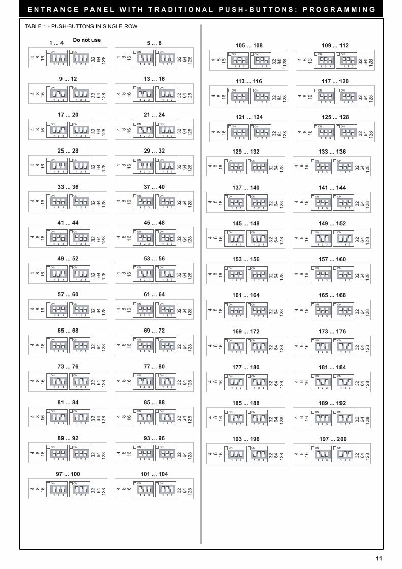
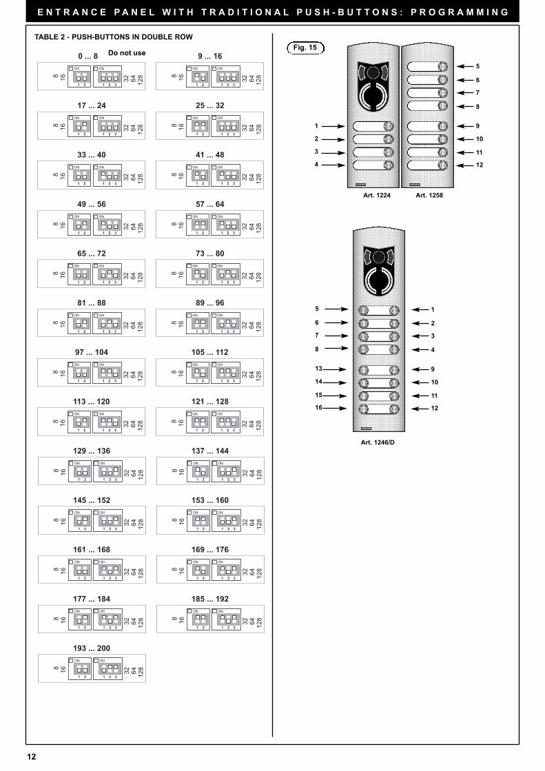
HARDWARE PROGRAMMING OF ADDITIONAL MODULE PUSH-
BUTTONS
The dip-switches modify the hardware code of the first pushbutton at
the top right of the module, while the other push-buttons are associated
consecutively from top t bottom, right to left (see Tables 1 and 2). Take
care not to overlap the codes of push-buttons on the same panel. When
using the modules with push-buttons in single or double rows the para-
meter “Single/Double push-buttons” must be programmed according to
the type of module (see standard or advanced programming pages 15
and pages 16).
Fig. 14
PUSHBUTTON HARDWARE PROGRAMMING
(Perform modifications with system switched off)
The hardware programming of push-buttons enables the assignment of
a unique hardware identification code to each pushbutton of the panel.
This operation is indispensable to distinguish each button of the panel
and should only be performed for additional module 805x and 804x. The
keys on the standard modules are already assigned with the numbers
from 1 to 8 and the relative hardware programming is not modifiable.
To associate the hardware code use the dip-switches in each additional
module below the white protection of the push-buttons. On 805x series
modules, with push-buttons in single rows, there are 6 dip-switches,
while the 804x series modules, with push-buttons in double rows, there
are 5 dip-switches.
ON
1 2 3
ON
1 2 3
5
6
7
ON
1 2 3
ON
1 2 3
8
ID ENTRANCE PANEL, IDENTIFICATION PANEL CODE
The identification panel code is required when there is more than one
entrance panel on the installation and only for the panels previously
identified as SLAVE. The operation must be carried out after connec-
ting all the entrance panels, carrying out the previous operations and
powering the installation.
Attention: if the installation power supplies are connected to the elctri-
cal network with more switchers, when switching the installation on,
first power the SLAVE entrance panels and then the MASTER entran-
ce panel.
Programming may be carried out by means of the programmer type
950C or the PC Software PC SaveProg or by push-buttons from the
entrance panels; if the entrance panel push-buttons are used it is
necessary have in the panel a number of push-buttons (different for
the physical code) equal to the number of SLAVE entrance panels.
For example:
1) in an installation with 9 entrance panels (1 Master and 8 Slaves) 8 dif-
ferent push-buttons for the 8 entrance panels, provided with the elec-
tronic unit.
2) in an installation with 11 entrance panels (1 Master and 10 Slaves) at
least 2 entrance panels out of 11 must be equipped with additional
modules to have, besides the 8 standard push-buttons, other 2 push-
bttons with different physical codes.
Panel ID programming procedure
Perform the following procedure for each of the SLAVE panels.
- Power up the system. Power first the SLAVE panels followed by the
MASTER panel.
- Wait until the red LEDs indicating ENGAGED/WAIT stop flashing.
- Press and hold the RESET pushbutton (see page 2), of the electro-
nic unit.
- Press and hold 1st pushbutton at the top right of the electronic unit
together with the RESET pushbutton.
- Release the RESET pushbutton while keeping pushbutton (top-right)
for 2 seconds.
- Wait for the panel to emit a high tone from the loudspeaker.
- Enter the Password by pressing the call push-buttons 6 - 5 - 4 - 3 -
2 - 1 in sequence. Each time a pushbutton is pressed, a short “Beep”
is sounded and the output time is renewed (25 seconds), until the
next pushbutton is pressed. The password can only be changed by
means of the programmer type 950C or the PC Software PC
SaveProg.
- If the password is correct, the panel emits a high tone of confirmation,
otherwise it emits a low tone and exits the programming phase. The
unit also exits the programming phase when the output time interval
elapses.
- Within 25 seconds, press one of push-buttons to assign the identifi-
cation code to the SLAVE panel. Pushbutton (top-right) corresponds
to panel 1 SLAVE (ID=2), pushbutton n°2 under n°1 to panel 2
SLAVE (ID=3) and so on.
If the identification code has already been assigned, the panel emits a
long high tone until another pushbutton is pressed. If the code is availa-
ble, the panel emits a low tone and exits the programming phase.
PRG
RESET
Fig. 13C
Caution!
In order to operate on the pro-
gramming (PRG) and Reset push-
buttons it is necessary to use the
proper tool usually supplied with
the electronic unit.
11
E N T R A N C E P A N E L W I T H T R A D I T I O N A L P U S H - B U T T O N S : P R O G R A M M I N G
ON
1 2 3
1684
ON
1 2 3 1286432
ON
1 2 3
1684
ON
1 2 3 1286432
ON
1 2 3
1684
ON
1 2 3 1286432
ON
1 2 3
1684
ON
1 2 3 1286432
ON
1 2 3
1684
ON
1 2 3 1286432
ON
1 2 3
1684
ON
1 2 3 1286432
ON
1 2 3
1684
ON
1 2 3 1286432
ON
1 2 3
1684
ON
1 2 3 1286432
ON
1 2 3
1684
ON
1 2 3 1286432
ON
1 2 3
1684ON
1 2 3 1286432
ON
1 2 3
1684
ON
1 2 3 1286432
ON
1 2 3
1684
ON
1 2 3 1286432
ON
1 2 3
1684
ON
1 2 3 1286432
ON
1 2 3
1684
ON
1 2 3 1286432
ON
1 2 3
1684
ON
1 2 3 1286432
ON
1 2 3
1684
ON
1 2 3 1286432
ON
1 2 3
1684
ON
1 2 3 1286432
ON
1 2 3
1684
ON
1 2 3 1286432
129 ... 132 133 ... 136
137 ... 140
145 ... 148
153 ... 156
161 ... 164
169 ... 172
177 ... 180
185 ... 188
193 ... 196
141 ... 144
149 ... 152
157 ... 160
165 ... 168
173 ... 176
181 ... 184
189 ... 192
197 ... 200
ON
1 2 3
1684
ON
1 2 3 1286432
ON
1 2 3
1684
ON
1 2 3 1286432
ON
1 2 3
1684
ON
1 2 3 1286432
ON
1 2 3
1684
ON
1 2 3 1286432
ON
1 2 3
1684
ON
1 2 3 1286432
ON
1 2 3
1684
ON
1 2 3 1286432
105 ... 108 109 ... 112
113 ... 116 117 ... 120
121 ... 124 125 ... 128
ON
1 2 3
1684
ON
1 2 3 1286432
ON
1 2 3
1684
ON
1 2 3 1286432
ON
1 2 3
1684
ON
1 2 3 1286432
ON
1 2 3
1684
ON
1 2 3 1286432
ON
1 2 3
1684
ON
1 2 3 1286432
ON
1 2 3
1684ON
1 2 3 1286432
ON
1 2 3
1684
ON
1 2 3 1286432
ON
1 2 3
1684
ON
1 2 3 1286432
ON
1 2 3
1684
ON
1 2 3 1286432
ON
1 2 3
1684
ON
1 2 3 1286432
ON
1 2 3
1684
ON
1 2 3 1286432
ON
1 2 3
1684
ON
1 2 3 1286432
ON
1 2 3
1684
ON
1 2 3 1286432
ON
1 2 3
1684
ON
1 2 3 1286432
ON
1 2 3
1684
ON
1 2 3 1286432
ON
1 2 3
1684
ON
1 2 3 1286432
ON
1 2 3
1684
ON
1 2 3 1286432
ON
1 2 3
1684
ON
1 2 3 1286432
ON
1 2 3
1684
ON
1 2 3 1286432
ON
1 2 3
1684
ON
1 2 3 1286432
ON
1 2 3
1684
ON
1 2 3 1286432
ON
1 2 3
1684
ON
1 2 3 1286432
ON
1 2 3
1684
ON
1 2 3 1286432
ON
1 2 3
1684
ON
1 2 3 1286432
ON
1 2 3
1684
ON
1 2 3 1286432
ON
1 2 3
1684
ON
1 2 3 1286432
1 ... 4 5 ... 8
9 ... 12
17 ... 20
25 ... 28
33 ... 36
41 ... 44
49 ... 52
57 ... 60
65 ... 68
73 ... 76
81 ... 84
13 ... 16
21 ... 24
29 ... 32
37 ... 40
45 ... 48
53 ... 56
61 ... 64
69 ... 72
77 ... 80
85 ... 88
89 ... 92 93 ... 96
97 ... 100 101 ... 104
TABLE 1 - PUSH-BUTTONS IN SINGLE ROW
Do not use
12
E N T R A N C E P A N E L W I T H T R A D I T I O N A L P U S H - B U T T O N S : P R O G R A M M I N G
ON
1 2
168
ON
1 2
168
ON
1 2
168
ON
1 2
168
ON
1 2 3 1286432
ON
1 2 3 1286432
ON
1 2 3 1286432
ON
1 2 3 1286432
ON
1 2
168
ON
1 2
168ON
1 2168
ON
1 2
168
ON
1 2 3 1286432
ON
1 2 3 1286432
ON
1 2 3 1286432
ON
1 2 3 1286432
ON
1 2
168
ON
1 2
168
ON
1 2
168
ON
1 2
168
ON
1 2 3 1286432
ON
1 2 3 1286432
ON
1 2 3 1286432
ON
1 2 3 1286432
ON
1 2
168
ON
1 2
168
ON
1 2
168
ON
1 2
168
ON
1 2 3 1286432
ON
1 2 3 1286432
ON
1 2 3 1286432
ON
1 2 3 1286432
ON
1 2
168
ON
1 2
168
ON
1 2
168
ON
1 2 3 1286432
ON
1 2 3 1286432
ON
1 2 3 1286432
ON
1 2
168
ON
1 2
168
ON
1 2
168
ON
1 2 3 1286432
ON
1 2 3 1286432
ON
1 2 3 1286432
ON
1 2
168
ON
1 2 3 1286432
ON
1 2
168
ON
1 2 3 1286432
ON
1 2
168
ON
1 2 3 1286432
0 ... 8 9 ... 16
17 ... 24
33 ... 40
49 ... 56
65 ... 72
81 ... 88
97 ... 104
113 ... 120
129 ... 136
145 ... 152
161 ... 168
177 ... 184
25 ... 32
41 ... 48
57 ... 64
73 ... 80
89 ... 96
105 ... 112
121 ... 128
137 ... 144
153 ... 160
169 ... 176
185 ... 192
193 ... 200
Fig. 15
Art. 1224 Art. 1258
1
2
3
4
5
11
10
9
8
7
6
12
Art. 1246/D
1
11
10
9
4
3
2
12
5
15
14
13
8
7
6
16
TABLE 2 - PUSH-BUTTONS IN DOUBLE ROW
Do not use
13
E N T R A N C E P A N E L W I T H T R A D I T I O N A L P U S H - B U T T O N S : P R O G R A M M I N G
LED switched off
LED switchwed on
DL3 DL4
DL5 DL6
SEQUENCE
NEXT
PREVIOUS
NEXT
DL3 DL4
DL5 DL6
PREVIOUS
NEXT
DL3 DL4
DL5 DL6
PREVIOUS
NEXT
DL3 DL4
DL5 DL6
PREVIOUS
NEXT
DL3 DL4
DL5 DL6
PREVIOUS
NEXT
DL3 DL4
DL5 DL6
PREVIOUS
NEXT
OK
END
DL3 DL4
DL5 DL6
PREVIOUS
NEXT
SINGLE/DOUBLE
PUSH-BUTTONS
OK
END
ANSWER
TIME
OK
END
CONVERSATION
TIME
OK
END
SELF-START
TIME
OK
END
LOCK
TIME
OK
END
F1
TIME
OKRESET
EEPROM
PROGRAMMING
EXIT
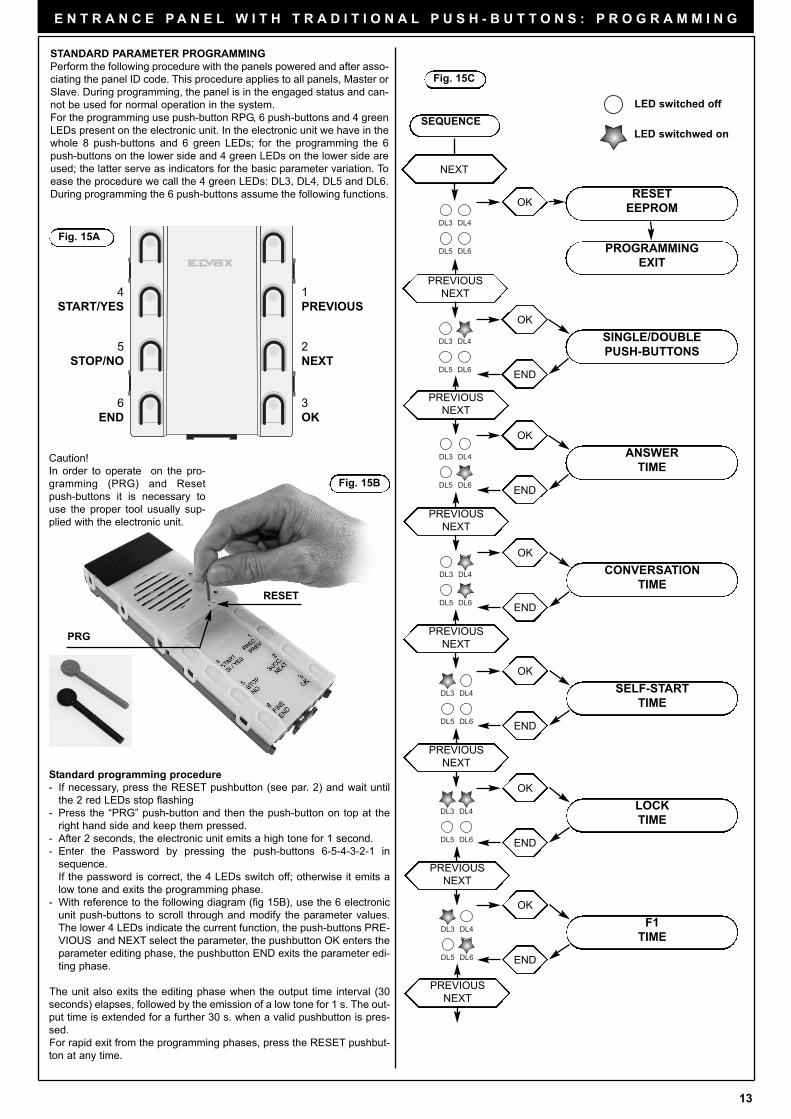
STANDARD PARAMETER PROGRAMMING
Perform the following procedure with the panels powered and after asso-
ciating the panel ID code. This procedure applies to all panels, Master or
Slave. During programming, the panel is in the engaged status and can-
not be used for normal operation in the system.
For the programming use push-button RPG, 6 push-buttons and 4 green
LEDs present on the electronic unit. In the electronic unit we have in the
whole 8 push-buttons and 6 green LEDs; for the programming the 6
push-buttons on the lower side and 4 green LEDs on the lower side are
used; the latter serve as indicators for the basic parameter variation. To
ease the procedure we call the 4 green LEDs: DL3, DL4, DL5 and DL6.
During programming the 6 push-buttons assume the following functions.
1
PREVIOUS
2
NEXT
3
OK
4
START/YES
5
STOP/NO
6
END
Fig. 15A
Standard programming procedure
- If necessary, press the RESET pushbutton (see par. 2) and wait until
the 2 red LEDs stop flashing
- Press the “PRG” push-button and then the push-button on top at the
right hand side and keep them pressed.
- After 2 seconds, the electronic unit emits a high tone for 1 second.
- Enter the Password by pressing the push-buttons 6-5-4-3-2-1 in
sequence.
If the password is correct, the 4 LEDs switch off; otherwise it emits a
low tone and exits the programming phase.
- With reference to the following diagram (fig 15B), use the 6 electronic
unit push-buttons to scroll through and modify the parameter values.
The lower 4 LEDs indicate the current function, the push-buttons PRE-
VIOUS and NEXT select the parameter, the pushbutton OK enters the
parameter editing phase, the pushbutton END exits the parameter edi-
ting phase.
The unit also exits the editing phase when the output time interval (30
seconds) elapses, followed by the emission of a low tone for 1 s. The out-
put time is extended for a further 30 s. when a valid pushbutton is pres-
sed.
For rapid exit from the programming phases, press the RESET pushbut-
ton at any time.
Fig. 15C
PRG
RESET
Fig. 15B
Caution!
In order to operate on the pro-
gramming (PRG) and Reset
push-buttons it is necessary to
use the proper tool usually sup-
plied with the electronic unit.
14
E N T R A N C E P A N E L W I T H T R A D I T I O N A L P U S H - B U T T O N S : P R O G R A M M I N G
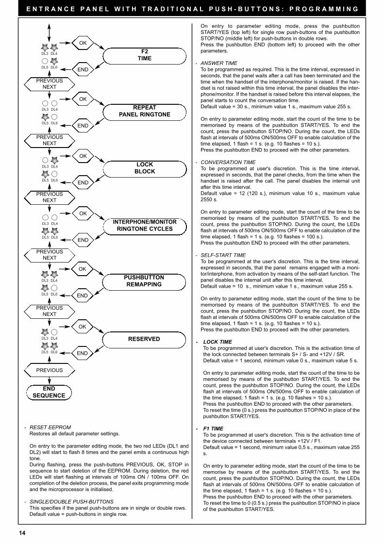
On entry to parameter editing mode, press the pushbutton
START/YES (top left) for single row push-buttons of the pushbutton
STOP/NO (middle left) for push-buttons in double rows.
Press the pushbutton END (bottom left) to proceed with the other
parameters.
- ANSWER TIMETo be programmed as required. This is the time interval, expressed in
seconds, that the panel waits after a call has been terminated and the
time when the handset of the interphone/monitor is raised. If the han-
dset is not raised within this time interval, the panel disables the inter-
phone/monitor. If the handset is raised before this interval elapses, the
panel starts to count the conversation time.
Default value = 30 s., minimum value 1 s., maximum value 255 s.
On entry to parameter editing mode, start the count of the time to be
memorised by means of the pushbutton START/YES. To end the
count, press the pushbutton STOP/NO. During the count, the LEDs
flash at intervals of 500ms ON/500ms OFF to enable calculation of the
time elapsed, 1 flash = 1 s. (e.g. 10 flashes = 10 s.).
Press the pushbutton END to proceed with the other parameters.
- CONVERSATION TIMETo be programmed at user's discretion. This is the time interval,
expressed in seconds, that the panel checks, from the time when the
handset is raised after the call. The panel disables the internal unit
after this time interval.
Default value = 12 (120 s.), minimum value 10 s., maximum value
2550 s.
On entry to parameter editing mode, start the count of the time to be
memorised by means of the pushbutton START/YES. To end the
count, press the pushbutton STOP/NO. During the count, the LEDs
flash at intervals of 500ms ON/500ms OFF to enable calculation of the
time elapsed, 1 flash = 1 s. (e.g. 10 flashes = 100 s.).
Press the pushbutton END to proceed with the other parameters.
- SELF-START TIMETo be programmed at the user's discretion. This is the time interval,
expressed in seconds, that the panel remains engaged with a moni-
tor/interphone, from activation by means of the self-start function. The
panel disables the internal unit after this time interval.
Default value = 10 s., minimum value 1 s., maximum value 255 s.
On entry to parameter editing mode, start the count of the time to be
memorised by means of the pushbutton START/YES. To end the
count, press the pushbutton STOP/NO. During the count, the LEDs
flash at intervals of 500ms ON/500ms OFF to enable calculation of the
time elapsed, 1 flash = 1 s. (e.g. 10 flashes = 10 s.).
Press the pushbutton END to proceed with the other parameters.
- LOCK TIMETo be programmed at user's discretion. This is the activation time of
the lock connected between terminals S+ / S- and +12V / SR.
Default value = 1 second, minimum value 0 s., maximum value 5 s.
On entry to parameter editing mode, start the count of the time to be
memorised by means of the pushbutton START/YES. To end the
count, press the pushbutton STOP/NO. During the count, the LEDs
flash at intervals of 500ms ON/500ms OFF to enable calculation of
the time elapsed, 1 flash = 1 s. (e.g. 10 flashes = 10 s.).
Press the pushbutton END to proceed with the other parameters.
To reset the time (0 s.) press the pushbutton STOP/NO in place of the
pushbutton START/YES.
- F1 TIMETo be programmed at user's discretion. This is the activation time of
the device connected between terminals +12V / F1.
Default value = 1 second, minimum value 0,5 s., maximum value 255
s.
On entry to parameter editing mode, start the count of the time to be
memorise by means of the pushbutton START/YES. To end the
count, press the pushbutton STOP/NO. During the count, the LEDs
flash at intervals of 500ms ON/500ms OFF to enable calculation of
the time elapsed, 1 flash = 1 s. (e.g. 10 flashes = 10 s.).
Press the pushbutton END to proceed with the other parameters.
To reset the time to 0 (0.5 s.) press the pushbutton STOP/NO in place
of the pushbutton START/YES.
DL3 DL4
DL5 DL6
PREVIOUS
NEXT
DL3 DL4
DL5 DL6
PREVIOUS
NEXT
DL3 DL4
DL5 DL6
PREVIOUS
NEXT
DL3 DL4
DL5 DL6
PREVIOUS
NEXT
OK
END
F2
TIME
OK
END
REPEAT
PANEL RINGTONE
OK
END
LOCK
BLOCK
OK
END
INTERPHONE/MONITOR
RINGTONE CYCLES
DL3 DL4
DL5 DL6
PREVIOUS
NEXT
OK
END
PUSHBUTTON
REMAPPING
DL3 DL4
DL5 DL6
OK
END
RESERVED
END
SEQUENCE
PREVIOUS
- RESET EEPROMRestores all default parameter settings.
On entry to the parameter editing mode, the two red LEDs (DL1 and
DL2) will start to flash 8 times and the panel emits a continuous high
tone.
During flashing, press the push-buttons PREVIOUS, OK, STOP in
sequence to start deletion of the EEPROM. During deletion, the red
LEDs will start flashing at intervals of 100ms ON / 100ms OFF. On
completion of the deletion process, the panel exits programming mode
and the microprocessor is initialised.
- SINGLE/DOUBLE PUSH-BUTTONSThis specifies if the panel push-buttons are in single or double rows.
Default value = push-buttons in single row.

15
E N T R A N C E P A N E L W I T H T R A D I T I O N A L P U S H - B U T T O N S : P R O G R A M M I N G
ADVANCED PARAMETER PROGRAMMING
Refer to the instructions for programmer type 950C.
- F2 TIMETo be programmed at user's discretion. This is the activation time of
the device connected between terminals +12V / F2.
Default value = 1 second, minimum value 0,5 s., maximum value 255
s.
On entry to parameter editing mode, start the count of the time to be
memorised by means of the pushbutton START/YES. To end the
count, press the pushbutton STOP/NO. During the count, the LEDs
flash at intervals of 500ms ON/500ms OFF to enable calculation of
the time elapsed, 1 flash = 1 s. (e.g. 10 flashes = 10 s.).
Press the pushbutton END to proceed with the other parameters.
To reset the time to 0 (0.5 s.) press the pushbutton STOP/NO in place
of the pushbutton START/YES.
- PANEL RINGTONE ENABLETo be programmed as required. Enables repetition of the call ringto-
ne in the loudspeaker of the panel, from the panel where the call is
being made.
Default value = enabled
On entry to parameter editing mode, press the pushbutton
START/YES to enable the function, or the pushbutton STOP/NO to
disable the function.
Press the pushbutton END (bottom left) to proceed with the other
parameters.
- PANEL LOCK BLOCKTo be programmed as required. Activation of the lock block enables
control of the lock only when the panel is in call, conversation or self-
start status.
Default value = block disabled
On entry to parameter editing mode, press the pushbutton
START/YES to enable the function, or the pushbutton STOP/NO to
disable the function.
Press the pushbutton END (bottom left) to proceed with the other
parameters.
- RINGTONE CYCLESTo be programmed at user's discretion. This is the number of times
that the call is repeated in the monitor/interphone when a call
pushbutton is pressed.
Default value = 2 times, minimum value 1, maximum value 20.
On entry to parameter editing mode, start thecount of the cycles to
memorised by means of the pushbutton START/YES. To end the
count, press the pushbutton STOP/NO. During the count, the LEDs
flash at intervals of 500ms ON/500ms OFF to enable calculation of
the number of cycles, 1 flash = 1 cycle (e.g. 5 flashes = 5 cycles).
Press the pushbutton END to proceed with the other parameters.
- PUSHBUTTON REMAPPINGEnables modification to the code sent by a pushbutton, regardless of
its physical position assigned with the hardware programming. This
enables use of a pushbutton to call an interphone /monitor that has
already been assigned a different code.
Default value = all push-buttons associated with a specific physical
code
On entry to parameter editing mode, the LEDs start flashing; to start
remapping, press the pushbutton START/YES (top left).
After pressing the pushbutton START/YES, press the call pushbutton
of the panel to be remapped. A general call is made from the panel to
all interphones/monitors in the rest condition (not in conversation);
the interphones/monitors with handset raised will emit a 3-tone
ascending scale from the loudspeaker.
From this moment the user has a 30-second interval to press, on the
interphone/monitor to be associated, the lock push-button.
The panel loudspeaker emits a low tone; this also occurs when the
30-second time interval elapses.ù
Press the pushbutton START/YES (top left) to remap other push-but-
tons or END (bottom left) to proceed with the other parameters.
To restore the default value (Hardware value) of a pushbutton, inste-
ad of pressing START/YES, press STOP/NO and then the pushbut-
ton to restore the default value and end the procedure.
During this procedure, if the lock pushbutton on the interphone/moni-
tor concerned is pressed, the panel lock is activated. To eliminate this
event, enable the parameter PANEL BLOCK.
16
I N T E R P H O N E / V I D E O I N T E R P H O N E
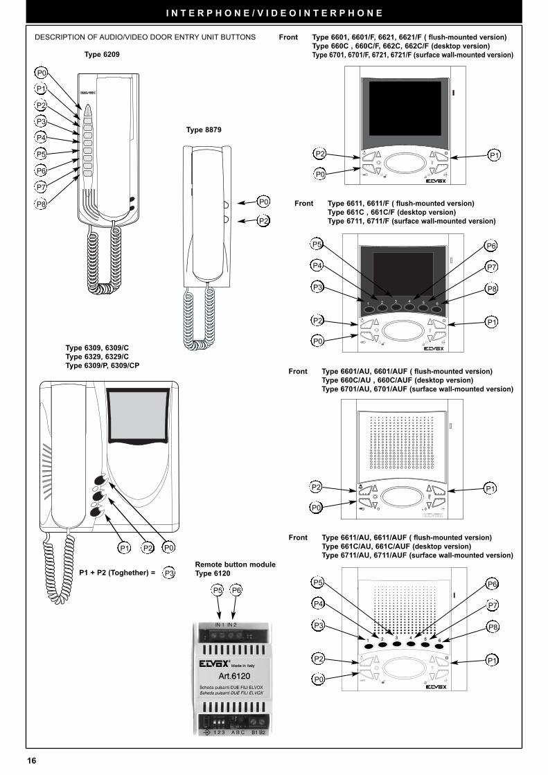
Type 6209
P1
P2
P0
P2 P0
P2
P1
P8
P6
P7
P5
P4
P3
P0
P1 + P2 (Toghether) = P3
Type 8879
Type 6309, 6309/C
Type 6329, 6329/C
Type 6309/P, 6309/CP
DESCRIPTION OF AUDIO/VIDEO DOOR ENTRY UNIT BUTTONS
P6P5
Remote button module
Type 6120
RESET
P4
P3
P2
P0
P5
P7
P8
P1
P6
P4
P3
P2
P0
P5
P7
P8
P6
P2
P0
P1
P2
P0
P1
P1
Front Type 6601, 6601/F, 6621, 6621/F ( flush-mounted version)
Type 660C , 660C/F, 662C, 662C/F (desktop version)
Type 6701, 6701/F, 6721, 6721/F (surface wall-mounted version)
Front Type 6611, 6611/F ( flush-mounted version)
Type 661C , 661C/F (desktop version)
Type 6711, 6711/F (surface wall-mounted version)
Front Type 6601/AU, 6601/AUF ( flush-mounted version)
Type 660C/AU , 660C/AUF (desktop version)
Type 6701/AU, 6701/AUF (surface wall-mounted version)
Front Type 6611/AU, 6611/AUF ( flush-mounted version)
Type 661C/AU, 661C/AUF (desktop version)
Type 6711/AU, 6711/AUF (surface wall-mounted version)
17
I N T E R P H O N E / V I D E O I N T E R P H O N E : I N T E R P H O N E I N S T A L L A T I O N 6 2 0 9
DESCRIPTION Type 6209
Type 6209 is an interphone in the Petrarca series for ELVOX TWO
WIRE audio and video door entry systems. It is supplied as standard
with 3 pushbuttons, one for lock release, one for self-start of the inter-
phone in the system even when not called, and one for the auxiliary “stair
light” service. The interphone can be fitted with an additional 3 pairs of
pushbutton types 692P (692P/M or 692P/R), for auxiliary services or
intercommunicating calls, and the accessory type 6153/682 for: call volu-
me adjustment, call signal mute, call denied luminous indicators, signal
to indicate unanswered calls, signal to indicate services not available
and luminous signal for gate/door open. The interphone can be installed
as a wall-mounted version or desktop using the conversion kit type 6140
or 6A40, or in combination with monitors in the Petrarca series type 6009
(b/w monitor) or type 6009/C (colour monitor) by means of wall bracket
type 6145 or desktop conversion kit type 6142 or 6A42.
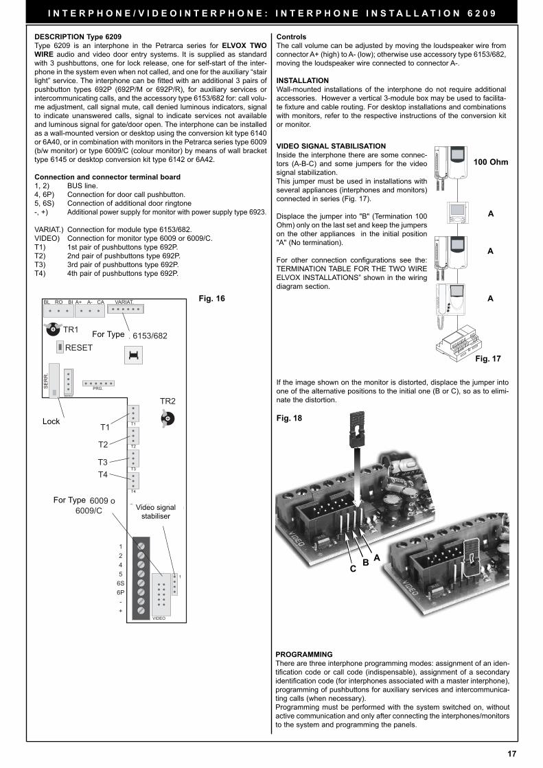
Connection and connector terminal board
1, 2) BUS line.
4, 6P) Connection for door call pushbutton.
5, 6S) Connection of additional door ringtone
-, +) Additional power supply for monitor with power supply type 6923.
VARIAT.) Connection for module type 6153/682.
VIDEO) Connection for monitor type 6009 or 6009/C.
T1) 1st pair of pushbuttons type 692P.
T2) 2nd pair of pushbuttons type 692P.
T3) 3rd pair of pushbuttons type 692P.
T4) 4th pair of pushbuttons type 692P.
BL BIRO A+ CAA- VARIAT.
SE
RR
.
SERIALE
PRG.
T1
T2
T3
T4
VIDEO
1
1245
6S6P-+
T1
T2
T3T4
Per art. 6153/682RESET
SERRATURA
Per art. 6009 o 6009/C Stabilizzazione
segnale video
TR1
TR2
Fig. 16
Video signal
stabiliser
Controls
The call volume can be adjusted by moving the loudspeaker wire from
connector A+ (high) to A- (low); otherwise use accessory type 6153/682,
moving the loudspeaker wire connected to connector A-.
INSTALLATION
Wall-mounted installations of the interphone do not require additional
accessories. However a vertical 3-module box may be used to facilita-
te fixture and cable routing. For desktop installations and combinations
with monitors, refer to the respective instructions of the conversion kit
or monitor.
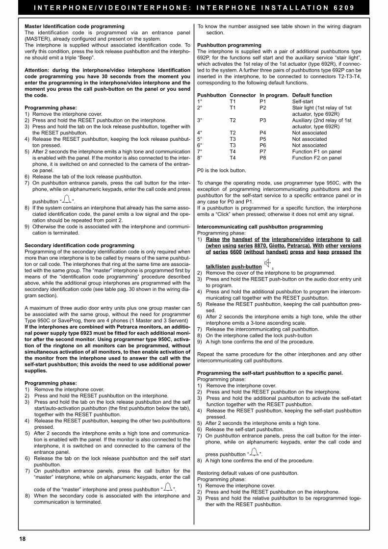
Fig. 17
100 Ohm
A
A
A
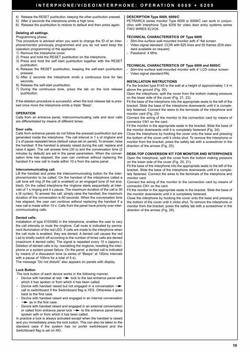
VIDEO SIGNAL STABILISATION
Inside the interphone there are some connec-
tors (A-B-C) and some jumpers for the video
signal stabilization.
This jumper must be used in installations with
several appliances (interphones and monitors)
connected in series (Fig. 17).
Displace the jumper into "B" (Termination 100
Ohm) only on the last set and keep the jumpers
on the other appliances in the initial position
"A" (No termination).
For other connection configurations see the:
TERMINATION TABLE FOR THE TWO WIRE
ELVOX INSTALLATIONS” shown in the wiring
diagram section.
Fig. 18
A
CB
If the image shown on the monitor is distorted, displace the jumper into
one of the alternative positions to the initial one (B or C), so as to elimi-
nate the distortion.
Lock
For Type
For Type
PROGRAMMING
There are three interphone programming modes: assignment of an iden-
tification code or call code (indispensable), assignment of a secondary
identification code (for interphones associated with a master interphone),
programming of pushbuttons for auxiliary services and intercommunica-
ting calls (when necessary).
Programming must be performed with the system switched on, without
active communication and only after connecting the interphones/monitors
to the system and programming the panels.
18
I N T E R P H O N E / V I D E O I N T E R P H O N E : I N T E R P H O N E I N S T A L L A T I O N 6 2 0 9
Master Identification code programming
The identification code is programmed via an entrance panel
(MASTER), already configured and present on the system.
The interphone is supplied without associated identification code. To
verify this condition, press the lock release pushbutton and the interpho-
ne should emit a triple “Beep”.
Attention: during the interphone/video interphone identification
code programming you have 30 seconds from the moment you
enter the programming in the interphone/video interphone and the
moment you press the call push-button on the panel or you send
the code.
Programming phase:
1) Remove the interphone cover.
2) Press and hold the RESET pushbutton on the interphone.
3) Press and hold the tab on the lock release pushbutton, together with
the RESET pushbutton.
4) Release the RESET pushbutton, keeping the lock release pushbut-
ton pressed.
5) After 2 seconds the interphone emits a high tone and communication
is enabled with the panel. If the monitor is also connected to the inter-
phone, it is switched on and connected to the camera of the entran-
ce panel.
6) Release the tab of the lock release pushbutton.
7) On pushbutton entrance panels, press the call button for the inter-
phone, while on alphanumeric keypads, enter the call code and press
pushbutton “ ”.
8) If the system contains an interphone that already has the same asso-
ciated identification code, the panel emits a low signal and the ope-
ration should be repeated from point 2.
9) Otherwise the code is associated with the interphone and communi-
cation is terminated.
Secondary identification code programming
Programming of the secondary identification code is only required when
more than one interphone is to be called by means of the same pushbut-
ton or call code. The interphones that ring at the same time are associa-
ted with the same group. The “master” interphone is programmed first by
means of the “identification code programming” procedure described
above, while the additional group interphones are programmed with the
secondary identification code (see table pag. 30 shown in the wiring dia-
gram section).
A maximum of three audio door entry units plus one group master can
be associated with the same group, without the need for programmer
Type 950C or SaveProg, there are 4 phones (1 Master and 3 Servent)
If the interphones are combined with Petrarca monitors, an additio-
nal power supply type 6923 must be fitted for each additional moni-
tor after the second monitor. Using programmer type 950C, activa-
tion of the ringtone on all monitors can be programmed, without
simultaneous activation of all monitors, to then enable activation of
the monitor from the interphone used to answer the call with the
self-start pushbutton; this avoids the need to use additional power
supplies.
Programming phase:
1) Remove the interphone cover.
2) Press and hold the RESET pushbutton on the interphone.
3) Press and hold the tab on the lock release pushbutton and the self
start/auto-activation pushbutton (the first pushbutton below the tab),
together with the RESET pushbutton.
4) Release the RESET pushbutton, keeping the other two pushbuttons
pressed.
5) After 2 seconds the interphone emits a high tone and communica-
tion is enabled with the panel. If the monitor is also connected to the
interphone, it is switched on and connected to the camera of the
entrance panel.
6) Release the tab on the lock release pushbutton and the self start
pushbutton.
7) On pushbutton entrance panels, press the call button for the
“master” interphone, while on alphanumeric keypads, enter the call
code of the “master” interphone and press pushbutton “ ”.
8) When the secondary code is associated with the interphone and
communication is terminated.
To know the number assigned see table shown in the wiring diagram
section.
Pushbutton programming
The interphone is supplied with a pair of additional pushbuttons type
692P, for the functions self start and the auxiliary service “stair light”,
which activates the 1st relay of the 1st actuator (type 692R), if connec-
ted to the system. A further three pairs of pushbuttons type 692P can be
inserted in the interphone, to be connected to connectors T2-T3-T4,
corresponding to the following default functions.
Pushbutton Connector In program. Default function
1° T1 P1 Self-start
2° T1 P2 Stair light (1st relay of 1st
actuator, type 692R)
3° T2 P3 Auxiliary (2nd relay of 1st
actuator, type 692R)
4° T2 P4 Not associated
5° T3 P5 Not associated
6° T3 P6 Not associated
7° T4 P7 Function F1 on panel
8° T4 P8 Function F2 on panel
P0 is the lock button.
To change the operating mode, use programmer type 950C, with the
exception of programming intercommunicating pushbuttons and the
pushbutton for the self-start service to a specific entrance panel or in
any case for P0 and P1.
If a pushbutton is programmed for a specific function, the interphone
emits a “Click” when pressed; otherwise it does not emit any signal.
Intercommunicating call pushbutton programming
Programming phase:
1) Raise the handset of the interphone/video interphone to call
(when using series 8870, Giotto, Petrarca). With other versions
of series 6600 (without handset) press and keep pressed the
talk/listen push-button .
2) Remove the cover of the interphone to be programmed.
3) Press and hold the RESET push-button on the audio door entry unit
to program.
4) Press and hold the additional pushbutton to program the intercom-
municating call together with the RESET pushbutton.
5) Release the RESET pushbutton, keeping the call pushbutton pres-
sed.
6) After 2 seconds the interphone emits a high tone, while the other
interphone emits a 3-tone ascending scale.
7) Release the intercommunicating call pushbutton.
8) On the interphone called the lock push-button
9) A high tone confirms the end of the procedure.
Repeat the same procedure for the other interphones and any other
intercommunicating call pushbuttons.
Programming the self-start pushbutton to a specific panel.
Programming phase:
1) Remove the interphone cover.
2) Press and hold the RESET pushbutton on the interphone.
3) Press and hold the additional pushbutton to activate the self-start
function together with the RESET pushbutton.
4) Release the RESET pushbutton, keeping the self-start pushbutton
pressed.
5) After 2 seconds the interphone emits a high tone.
6) Release the self-start pushbutton.
7) On pushbutton entrance panels, press the call button for the inter-
phone, while on alphanumeric keypads, enter the call code and
press pushbutton “ ”.
8) A high tone confirms the end of the procedure.
Restoring default values of one pushbutton.
Programming phase:
1) Remove the interphone cover.
2) Press and hold the RESET pushbutton on the interphone.
3) Press and hold the relative pushbutton to be reprogrammed toge-
ther with the RESET pushbutton.
19
I N T E R P H O N E / V I D E O I N T E R P H O N E : O P E R A T I O N 6 0 0 9 + 6 2 0 9
4) Release the RESET pushbutton, keeping the other pushbutton pressed.
5) After 2 seconds the interphone emits a high tone.
6) Release the pushbutton to restore to default and then press again.
Deleting all settings.
Programming phase:
This procedure is advised when you want to change the ID of an inter-
phone/monitor previously programmed and you do not want keep the
operation programming of the appliance.
1) Remove the interphone cover.
2) Press and hold the RESET pushbutton on the interphone.
3) Press and hold the self start pushbutton together with the RESET
pushbutton.
4) Release the RESET pushbutton, keeping the self-start pushbutton
pressed.
5) After 2 seconds the interphone emits a continuous tone for two
seconds.
6) Release the self-start pushbutton.
7) During the continuous tone, press the tab on the lock release
pushbutton.
If the deletion procedure is successful, when the lock release tab is pres-
sed once more the interphone emits a triple “Beep”.
OPERATION
Calls from an entrance panel, intercommunicating calls and door calls
are differentiated by means of different tones.
Door calls.
Calls from entrance panels do not follow the pressed pushbutton but are
generated inside the interphone. The call interval is 1 s of ringtone and
2 s of pause repeated twice (default value set on panel). To answer, raise
the handset. If the handset is already raised during the call, replace and
raise it again. The call answer time (30 s) and the conversation time (2
minutes by default) are set in the panel parameters. When the conver-
sation time has elapsed, the user can continue without replacing the
handset if a new call is made within 10 s from the same panel.
Intercommunicating call.
Lift the handset and press the intercommunicating button for the inter-
phone/monitor to be called. On the handset of the interphone called a
call tone will ring (if the call is enabled) or an engaged tone (if not ena-
bled). On the called interphone the ringtone starts sequentially at inter-
vals of 1 s ringing and 4 s pause. The maximum duration of the call is 30
s (6 cycles). To answer the call, simply raise the handset; the maximum
duration of the conversation is 60 seconds. When the conversation time
has elapsed, the user can continue without replacing the handset if a
new call is made within 10 s. Calls from the panel have priority over inter-
communicating calls.
Denied calls.
Installation of type 6153/682 in the interphone, enables the user to vary
the call intensity or mute the ringtone. Call mute is indicated by perma-
nent illumination of the red LED. If calls are made to the interphone when
the call mute is enabled, they are denied. A denied call causes the red
Led to briefly switch off according to the number of times calls are denied
(maximum 4 denied calls). The signal is repeated every 10 s (approx.).
Deletion of denied calls is by: reenabling the ringtone, resetting the inter-
phone or a system power failure. On the panel, a denied call is indicated
by means of a dissuasion tone (a series of “Beeps” at 100ms intervals
with a pause of 100ms for a total of 5 s).
The message “Do not disturb” also appears on panels with display.
Lock Button
The lock button of each device works in the following manner.
- Device with handset at rest lock to the last entrance panel with
which it has spoken or from which it has been called.
- Device with handset raised but not engaged in a conversation
call to switchboard if the Switchboard flag is YES. Otherwise it goes
back to the first case.
- Device with handset raised and engaged in an internal conversation
as in the first case.
- Device with handset raised and engaged in an external conversation
or called from entrance panel lock to the entrance panel being
spoken with or from which it has been called.
In practice a lock is always activated except when the handset is raised
and you immediately press the lock button. This can also be taken to the
standard case if the system has no porter switchboard and the
Switchboard flag is set on NO.
TECHNICAL CHARACTERISTICS OF Type 6009 and 6009/C
- Slim-line surface wall-mounted monitor with 4” LCD colour screen
- Video signal standard:PAL
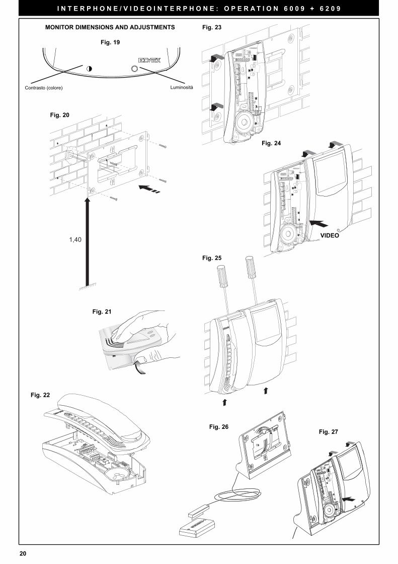
INSTALLATION INSTRUCTIONS
Fix the bracket type 6145 to the wall at a height of approximately 1.4 m
above the ground (Fig. 20).
Open the interphone, split the cover from the bottom making pressure
on the lower side of the cover (Fig. 21, 22).
Fit the base of the interphone into the appropriate seats to the left of the
bracket. Slide the base of the interphone downwards until it is comple-
tely fastened. Connect the wires to the terminals of the interphone and
monitor card (Fig. 23)
Connect the wiring of the monitor to the connection card by means of
connector CN1 on the card.
Fit the monitor in the appropriate seats in the bracket. Slide the base of
the monitor downwards until it is completely fastened (Fig. 24).
Close the interphone by hooking the cover onto the base and pressing
the bottom of the cover until it clicks shut. To remove the interphone or
monitor from the bracket, press the safety tab with a screwdriver in the
direction of the arrows (Fig. 25).
DESK-TOP CONVERSION KIT FOR MONITOR AND INTERPHONES
Open the interphone, split the cover from the bottom making pressure
on the lower side of the cover (Fig. 20, 21).
Fit the base of the interphone into the appropriate seats to the left of the
bracket. Slide the base of the interphone downwards until it is comple-
tely fastened. Connect the wires to the terminals of the interphone and
monitor card.
Connect the wiring of the monitor to the connection card by means of
connector CN1 on the card.
Fit the monitor in the appropriate seats in the bracket. Slide the base of
the monitor downwards until it is completely fastened.
Close the interphone by hooking the cover onto the base and pressing
the bottom of the cover until it clicks shut. To remove the interphone or
monitor from the bracket, press the safety tab with a screwdriver in the
direction of the arrows (Fig. 28).
DESCRIPTION Type 6009, 6009/C
PETRARCA series monitor Type 6009 or 6009/C can work in conjun-
ction with interphone Type 6209 for video door entry systems series
TWO WIRES ELVOX.
TECHNICAL CHARACTERISTICS OF Type 6009
- Slim-line surface wall-mounted monitor with 4” flat screen
- Video signal standard: CCIR with 625 lines and 50 frames (EIA stan-
dard available on request)
- Passband: 4 MHz
20
I N T E R P H O N E / V I D E O I N T E R P H O N E : O P E R A T I O N 6 0 0 9 + 6 2 0 9
MONITOR DIMENSIONS AND ADJUSTMENTS Fig. 23
Fig. 24
VIDEO
Fig. 25
Fig. 26
1,40
Fig. 20
Fig. 21
Fig. 22
Contrasto (colore) Luminosità
Fig. 19
Fig. 27
21
I N T E R P H O N E / V I D E O I N T E R P H O N E : I N T E R P H O N E I N S T A L L A T I O N 6 2 0 9
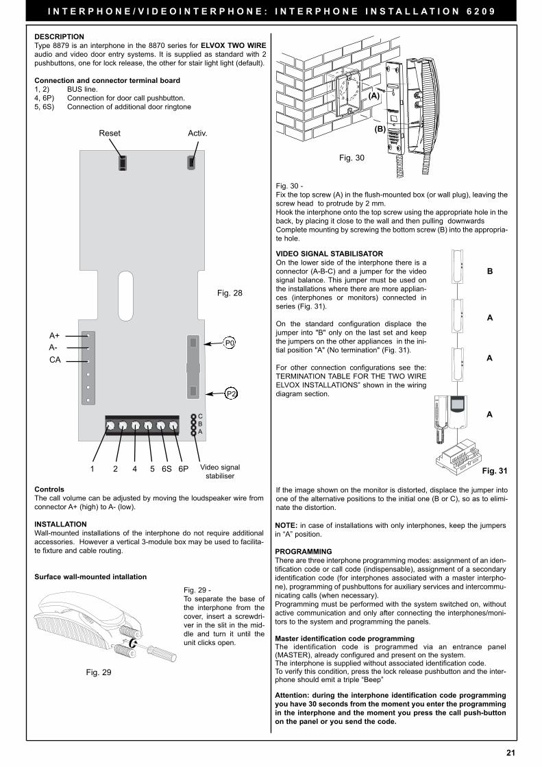
DESCRIPTION
Type 8879 is an interphone in the 8870 series for ELVOX TWO WIRE
audio and video door entry systems. It is supplied as standard with 2
pushbuttons, one for lock release, the other for stair light light (default).
Connection and connector terminal board
1, 2) BUS line.
4, 6P) Connection for door call pushbutton.
5, 6S) Connection of additional door ringtone
Controls
The call volume can be adjusted by moving the loudspeaker wire from
connector A+ (high) to A- (low).
INSTALLATION
Wall-mounted installations of the interphone do not require additional
accessories. However a vertical 3-module box may be used to facilita-
te fixture and cable routing.
Surface wall-mounted intallation
Video signal
stabiliser
Reset Activ.
C
B
A
6P6S5421
A+
A-
CA
Fig. 29
Fig. 29 -
To separate the base of
the interphone from the
cover, insert a screwdri-
ver in the slit in the mid-
dle and turn it until the
unit clicks open.
Fig. 28
P2
P0
Fig. 30 -
Fix the top screw (A) in the flush-mounted box (or wall plug), leaving the
screw head to protrude by 2 mm.
Hook the interphone onto the top screw using the appropriate hole in the
back, by placing it close to the wall and then pulling downwards
Complete mounting by screwing the bottom screw (B) into the appropria-
te hole.
Fig. 30
(A)
(B)
VIDEO SIGNAL STABILISATOR
On the lower side of the interphone there is a
connector (A-B-C) and a jumper for the video
signal balance. This jumper must be used on
the installations where there are more applian-
ces (interphones or monitors) connected in
series (Fig. 31).
On the standard configuration displace the
jumper into "B" only on the last set and keep
the jumpers on the other appliances in the ini-
tial position "A" (No termination" (Fig. 31).
For other connection configurations see the:
TERMINATION TABLE FOR THE TWO WIRE
ELVOX INSTALLATIONS” shown in the wiring
diagram section.
If the image shown on the monitor is distorted, displace the jumper into
one of the alternative positions to the initial one (B or C), so as to elimi-
nate the distortion.
B
A
A
A
NOTE: in case of installations with only interphones, keep the jumpers
in “A” position.
PROGRAMMING
There are three interphone programming modes: assignment of an iden-
tification code or call code (indispensable), assignment of a secondary
identification code (for interphones associated with a master interpho-
ne), programming of pushbuttons for auxiliary services and intercommu-
nicating calls (when necessary).
Programming must be performed with the system switched on, without
active communication and only after connecting the interphones/moni-
tors to the system and programming the panels.
Master identification code programmingThe identification code is programmed via an entrance panel(MASTER), already configured and present on the system.The interphone is supplied without associated identification code. To verify this condition, press the lock release pushbutton and the inter-phone should emit a triple “Beep”
Attention: during the interphone identification code programming
you have 30 seconds from the moment you enter the programming
in the interphone and the moment you press the call push-button
on the panel or you send the code.
Fig. 31
22
4) Press and hold the stair light pushbutton to make the intercommuni-
cating call together with the RESET pushbutton.
5) Release the RESET pushbutton, keeping the stair light pushbutton
pressed.
6) After 2 seconds the interphone emits a high tone, while the other
interphone emits a 3-tone ascending scale.
7) Release the stair light pushbutton.
8) On the interphone called (with the 3-tone ring), press lock push-but-
ton
9) A high tone confirms the end of the procedure.
Programming the self-start pushbutton to a specific panel.
Programming phase:
1) Remove the interphone cover.
2) Press and hold the RESET pushbutton on the interphone.
3) Press and hold the stair light pushbutton together with the RESET
pushbutton.
4) Release the RESET pushbutton, keeping the stair light pushbutton
pressed.
5) After 2 seconds the interphone emits a high tone.
6) Release the self start pushbutton.
7) On pushbutton entrance panels, press the call button for the inter-
phone, while on alphanumeric keypads, enter the call code and
press pushbutton “ ”.
8) A high tone confirms the end of the procedure.
Restoring default values of pushbutton (for stair light (P2).
Programming phase:
1) Remove the interphone cover.
2) Press and hold the RESET pushbutton on the interphone.
3) Press and hold the relative stair light pushbutton together with the
RESET pushbutton.
4) Release the RESET pushbutton, keeping stair light push-button pressed.
5) After 2 seconds the interphone emits a high tone.
6) Release the stair light pushbutton and then press again.
Deleting all settings.
Programming phase:
1) Remove the interphone cover.
2) Press and hold the RESET pushbutton on the interphone.
3) Press and hold the self start pushbutton (ATTIV) together with the
RESET ATTIV. pushbutton.
4) Release the RESET pushbutton, keeping the self-start pushbutton
pressed.
5) After 2 seconds the interphone emits a continuous tone for two
seconds.
6) Release the self-start pushbutton.
7) During the continuous tone, press the tab on the lock release
pushbutton.
If the deletion procedure is successful, when the lock release tab is pres-
sed once more the interphone emits a triple “Beep”.
OPERATION
Calls from an entrance panel, intercommunicating calls and door calls
are differentiated by means of different tones.
Door calls.
Calls from entrance panels do not follow the pressed pushbutton but are
generated inside the interphone. The call interval is 1 second of ringto-
ne and 2 seconds of pause repeated twice (default value set on panel).
To answer, raise the handset. If the handset is already raised during the
call, replace and raise it again. The call answer time (30 s) and the con-
versation time (2 minutes by default) are set in the panel parameters.
When the conversation time has elapsed, the user can continue without
replacing the handset if a new call is made within 10 seconds from the
same panel.
Intercommunicating call.
Lift the handset and press the intercommunicating button for the inter-
phone/monitor to be called. On the handset of the interphone called a
call tone will ring (if the call is enabled) or an engaged tone (if not ena-
bled). On the called interphone the ringtone starts sequentially at inter-
vals of 1 second ringing and 4 seconds pause. The maximum duration
of the call is 30 seconds (6 cycles). To answer the call, simply raise the
handset; the maximum duration of the conversation is 5 minutes. When
the conversation time has elapsed, the user can continue without repla-
cing the handset if a new call is made within 10 seconds. Calls from the
panel have priority over intercommunicating calls.
I N T E R P H O N E / V I D E O I N T E R P H O N E : I N T E R P H O N E I N S T A L L A T I O N 8 8 7 9
Programming phase:
1) Remove the interphone cover.
2) Press and hold the RESET pushbutton on the interphone.
3) Press and hold the tab on the lock release pushbutton, together with
the RESET pushbutton.
4) Release the RESET pushbutton, keeping the lock release pushbut-
ton pressed.
5) After 2 seconds the interphone emits a high tone and communication
is enabled with the panel.
6) Release the tab of the lock release pushbutton.
7) On pushbutton entrance panels, press the call button for the inter-
phone, while on alphanumeric keypads, enter the call code and press
pushbutton “ ”.
8) If the system contains an interphone that already has the same asso-
ciated identification code, the panel emits a low signal and the ope-
ration should be repeated from point 2.
9) Otherwise the code is associated with the interphone and communi-
cation is terminated.
Secondary identification code programmingProgramming of the secondary identification code is only required whenmore than one interphone is to be called by means of the same pushbut-ton or call code. The interphones that ring at the same time are associa-ted with the same group. The “master” interphone is programmed first bymeans of the “identification code programming” procedure describedabove, while the additional group interphones are programmed with thesecondary identification code (see table (see table shown in the wiringdiagram section).).A maximum of three audio door entry units plus one group master canbe associated with the same group, without the need for programmerType 950C or SaveProg .
Programming phase:
1) Remove the interphone cover.
2) Press and hold the RESET pushbutton on the interphone.
3) Press and hold the tab on the lock release pushbutton and the self
start/auto-activation (on top right hand side) pushbutton (Attiv-top on
the right hand side) together with the RESET pushbutton.
4) Release the RESET pushbutton, keeping the other two pushbuttons
pressed.
5) After 2 seconds the interphone emits a high tone and communica-
tion is enabled with the panel.
6) Release the tab on the lock release pushbutton and the self start
pushbutton.
7) On pushbutton entrance panels, press the call button for the
“master” interphone, while on alphanumeric keypads, enter the call
code of the “master” interphone and press pushbutton “ ”.
8) When the secondary code is associated with the interphone and
communication is terminated.
To know the number assigned see table see table shown in the wiring
diagram section.
Pushbutton programming
The interphone is supplied with a pushbutton, for the functions auxiliary
service “stair light”, which activates the 1st relay of the 1st actuator (type
69RH). To change the operating mode of push-button, use programmer
type 950C or SaveProg, with the exception of the programming push-
button as intercommunicating or for the self-start service associated with
a specific panel.
If a pushbutton is programmed for a specific function, the interphone
emits a “Click” when pressed; otherwise it does not emit any signal.
Intercommunicating call pushbutton programming
Programming phase:
1) Raise the handset of the interphone/video interphone to call
(when using series 8870, Giotto, Petrarca). With other versions
of series 6600 (without handset) press and keep pressed the
talk/listen push-button .
2) Remove the cover of the interphone to be programmed.
3) Press and hold the RESET push-button on the audio door entry unit
to program.
23
I N T E R P H O N E / V I D E O I N T E R P H O N E : I N T E R P H O N E I N S T A L L A T I O N 8 8 7 9
Lock Button
The lock button of each device works in the following manner.
- Device with handset at rest lock to the last entrance panel with
which it has spoken or from which it has been called.
- Device with handset raised but not engaged in a conversation
call to switchboard if the Switchboard flag is YES. Otherwise it goes
back to the first case.
- Device with handset raised and engaged in an internal conversation
as in the first case.
- Device with handset raised and engaged in an external conversation
or called from entrance panel lock to the entrance panel being
spoken with or from which it has been called.
In practice a lock is always activated except when the handset is raised
and you immediately press the lock button. This can also be taken to the
standard case if the system has no porter switchboard and the
Switchboard flag is set on NO.
PANEL OPERATION
Calls
The tone generated by the interphones/monitors, when a call is made
from a panel, does not follow the lenght of the pression of the pushbut-
ton, but is generated by the value of the “ringtone cycles” set on the
panel (default value = 2). Each ringtone cycle consist of 1 s ringtone and
2 s pause. On start of the call, the monitor of the relative video entrance
panel called switches on. At the end of the call, the answer time count
starts, within which the handset must be raised to answer the call. From
the time that the handset is raised, which can also occur during the call,
the conversation time count is starts (default value = 2 minutes). When
the conversation time has elapsed, the user has 10 s to press the call
pushbutton in order, to proceed with the conversation without hanging up
the handset. If a call is made from a panel outside this 10 s interval, while
the handset is still raised, press and then release the handset hook to
answer the call.
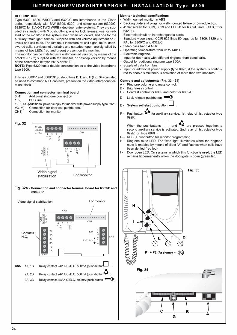
24
ELVOXCS2350271103
4 3 2 1A S+ B
US
1 2 1 3 V 3 M
EX
T. 24V
F.P.+ -CN
2 CBA
CN1
Stabilizzazionesegnale video Per monitor
Fig. 32
AC B
G
Fig. 34
Monitor technical specifications
- Wall-mounted monitor in ABS
- Backing plate and plugs for wall-mounted fixture or 3-module box.
- 4" flat screen for 6309, 6329 and LCD 4” for 6309/C and LCD 3,5” for
6329/C.
- Electronic circuit on interchangeable cards.
- Standard video signal CCIR 625 lines 50 squares for 6309, 6329 and
PAL for 6309/C and 6329/C.
- Video pass band 4 MHz
- Operating temperature from 0° to +40° C.
- Electronic ringtone.
- Input for door calls with different ringtone from panel calls.
- Output for additional ringtone type 860A.
- Supply of data from bus.
- Input for additional power supply (type 6923) if the system is configu-
red to enable simultaneous activation of more than two monitors.
Controls and adjustments (Fig. 33 - 34)
A - Ringtone volume and mute control.
B - Brightness control.
C - Contrast control for 6309 and color for 6309/C
D - Lock release pushbutton .
E - System self-start pushbutton .
F - Pushbutton for auxiliary service, 1st relay of 1st actuator type
692R.
When the pushbuttons and are pressed together, a
second auxiliary service is activated, 2nd relay of 1st actuator type
692R (or Type 69RH).
G - RESET pushbutton for monitor programming.
H - Ringtone mute LED. The fixed light illuminates when the ringtone
mute is enabled by means of slider "A" and flashes when calls have
been denied (red led).
I - Door open LED. On systems in which this function is used, the LED
remains lit permanently when the door/gate is open (green led).
Video signal
stabilization For monitor
DESCRIPTION
Type 6309, 6329, 6309/C and 6329/C are interphones in the Giotto
series respectively with B/W (6309, 6329) and colour screen (6309/C,
6329/C) for ELVOX TWO WIRE video door entry systems. They are sup-
plied as standard with 3 pushbuttons, one for lock release, one for self-
start of the monitor in the system even when not called, and one for the
auxiliary “stair light” service. Supplied with call volume adjustment on 3
levels and call mute. The luminous indicators of: call signal mute, unan-
swered calls, services not available and gate/door open, are signalled by
means of two LEDs (red and green) present on the monitor.
The monitor can be installed as a wall-mounted version, by means of the
bracket (R682) supplied with the monitor, or desktop version by means
of the conversion kit type 661A or 661F.
NOTE: Type 6329 has a double consumption as to the video interphone
type 6309.
In types 6309/P and 6309/CP push-buttons D, E and F (Fig. 34) can also
be used to command N.O. contacts, present on the video-interphone ter-
minal block.
Connection and connector terminal board
3, 4) Additional ringtone connection
1, 2) BUS line.
12 +, 13 -)Additional power supply for monitor with power supply type 6923.
V3, M) Connection for door call pushbutton.
CN1) Connection for monitor.
I N T E R P H O N E / V I D E O I N T E R P H O N E : I N S T A L L A T I O N T y p e 6 3 0 9
DFE
H
I
Fig. 33
P1 P2 P0
P1 + P2 (Assieme) = P3
Fig. 32a - Connection and connector terminal board for 6309/P and
6309/CP
CN5 1A, 1B Relay contact 24V A.C./D.C. 500mA (push-button )
2A, 2B Relay contact 24V A.C./D.C. 500mA (push-button )
3A, 3B Relay contact 24V A.C./D.C. 500mA (push-button ).
Video signal stabilization For monitor
4 3 2 1A S+ B
US
CN
1 CBA CN4
EXT. 24V
F.P.
M V
3 1
3 1
2
CN3
CN5
CN2
1A
1B
2A
2B
3A
3BContacts
N.O.
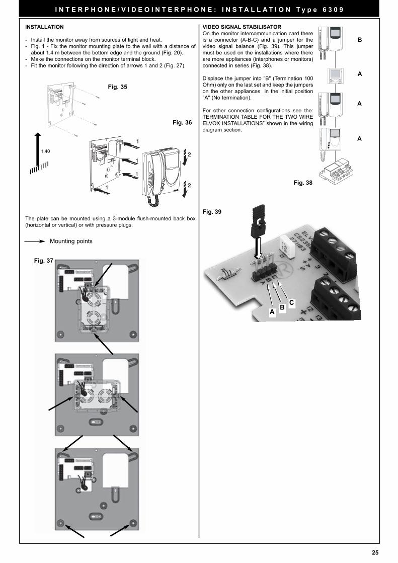
25
Fig. 37
Fig. 39
A
Fig. 38
BC
Mounting points
The plate can be mounted using a 3-module flush-mounted back box
(horizontal or vertical) or with pressure plugs.
VIDEO SIGNAL STABILISATOR
On the monitor intercommunication card there
is a connector (A-B-C) and a jumper for the
video signal balance (Fig. 39). This jumper
must be used on the installations where there
are more appliances (interphones or monitors)
connected in series (Fig. 38).
Displace the jumper into "B" (Termination 100
Ohm) only on the last set and keep the jumpers
on the other appliances in the initial position
"A" (No termination).
For other connection configurations see the:
TERMINATION TABLE FOR THE TWO WIRE
ELVOX INSTALLATIONS” shown in the wiring
diagram section.
B
A
A
A
I N T E R P H O N E / V I D E O I N T E R P H O N E : I N S T A L L A T I O N T y p e 6 3 0 9
INSTALLATION
- Install the monitor away from sources of light and heat.
- Fig. 1 - Fix the monitor mounting plate to the wall with a distance of
about 1.4 m between the bottom edge and the ground (Fig. 20).
- Make the connections on the monitor terminal block.
- Fit the monitor following the direction of arrows 1 and 2 (Fig. 27).
1
1
1
2
2
1
1,40
Fig. 35
Fig. 36
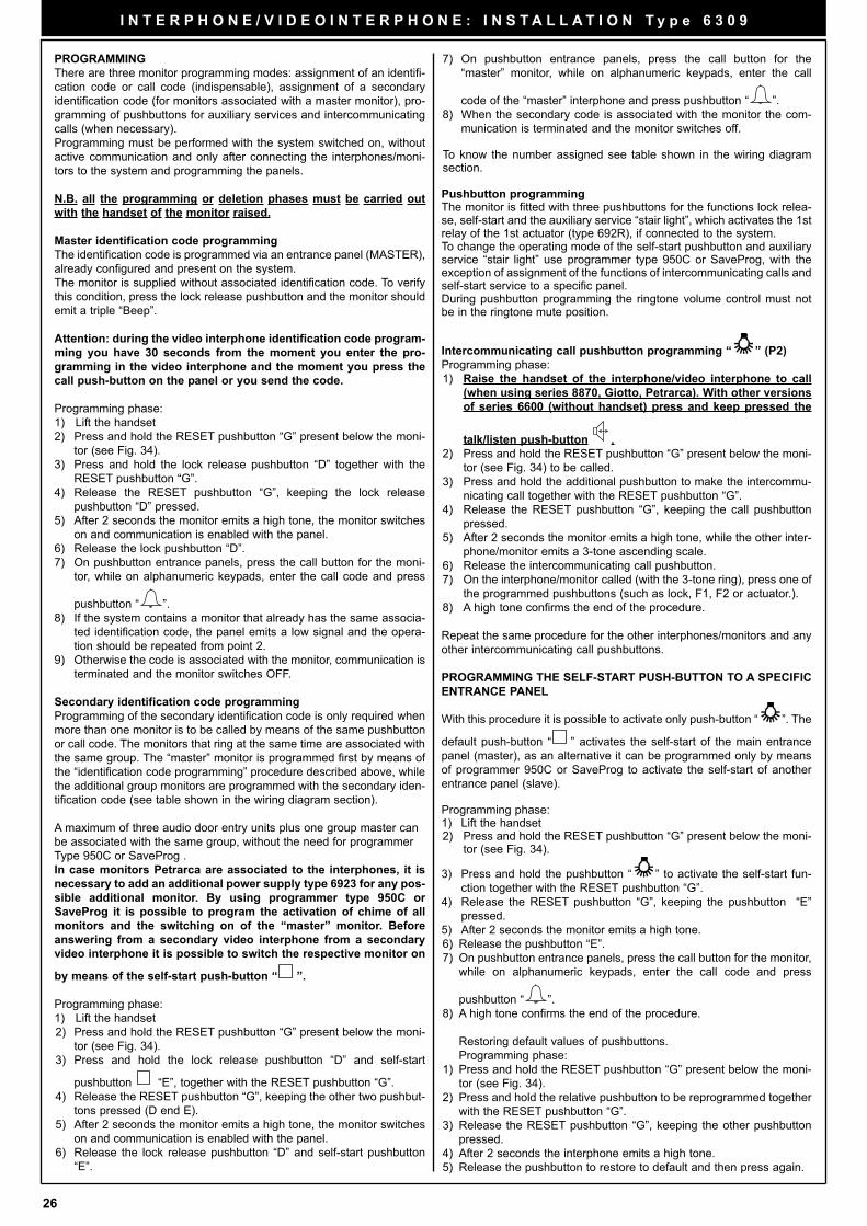
26
I N T E R P H O N E / V I D E O I N T E R P H O N E : I N S T A L L A T I O N T y p e 6 3 0 9
PROGRAMMING
There are three monitor programming modes: assignment of an identifi-
cation code or call code (indispensable), assignment of a secondary
identification code (for monitors associated with a master monitor), pro-
gramming of pushbuttons for auxiliary services and intercommunicating
calls (when necessary).
Programming must be performed with the system switched on, without
active communication and only after connecting the interphones/moni-
tors to the system and programming the panels.
N.B. all the programming or deletion phases must be carried out
with the handset of the monitor raised.
Master identification code programming
The identification code is programmed via an entrance panel (MASTER),
already configured and present on the system.
The monitor is supplied without associated identification code. To verify
this condition, press the lock release pushbutton and the monitor should
emit a triple “Beep”.
Attention: during the video interphone identification code program-
ming you have 30 seconds from the moment you enter the pro-
gramming in the video interphone and the moment you press the
call push-button on the panel or you send the code.
Programming phase:
1) Lift the handset
2) Press and hold the RESET pushbutton “G” present below the moni-
tor (see Fig. 34).
3) Press and hold the lock release pushbutton “D” together with the
RESET pushbutton “G”.
4) Release the RESET pushbutton “G”, keeping the lock release
pushbutton “D” pressed.
5) After 2 seconds the monitor emits a high tone, the monitor switches
on and communication is enabled with the panel.
6) Release the lock pushbutton “D”.
7) On pushbutton entrance panels, press the call button for the moni-
tor, while on alphanumeric keypads, enter the call code and press
pushbutton “ ”.
8) If the system contains a monitor that already has the same associa-
ted identification code, the panel emits a low signal and the opera-
tion should be repeated from point 2.
9) Otherwise the code is associated with the monitor, communication is
terminated and the monitor switches OFF.
Secondary identification code programming
Programming of the secondary identification code is only required when
more than one monitor is to be called by means of the same pushbutton
or call code. The monitors that ring at the same time are associated with
the same group. The “master” monitor is programmed first by means of
the “identification code programming” procedure described above, while
the additional group monitors are programmed with the secondary iden-
tification code (see table shown in the wiring diagram section).
A maximum of three audio door entry units plus one group master can
be associated with the same group, without the need for programmer
Type 950C or SaveProg .
In case monitors Petrarca are associated to the interphones, it is
necessary to add an additional power supply type 6923 for any pos-
sible additional monitor. By using programmer type 950C or
SaveProg it is possible to program the activation of chime of all
monitors and the switching on of the “master” monitor. Before
answering from a secondary video interphone from a secondary
video interphone it is possible to switch the respective monitor on
by means of the self-start push-button “ ”.
Programming phase:
1) Lift the handset
2) Press and hold the RESET pushbutton “G” present below the moni-
tor (see Fig. 34).
3) Press and hold the lock release pushbutton “D” and self-start
pushbutton “E”, together with the RESET pushbutton “G”.
4) Release the RESET pushbutton “G”, keeping the other two pushbut-
tons pressed (D end E).
5) After 2 seconds the monitor emits a high tone, the monitor switches
on and communication is enabled with the panel.
6) Release the lock release pushbutton “D” and self-start pushbutton
“E”.
7) On pushbutton entrance panels, press the call button for the
“master” monitor, while on alphanumeric keypads, enter the call
code of the “master” interphone and press pushbutton “ ”.
8) When the secondary code is associated with the monitor the com-
munication is terminated and the monitor switches off.
To know the number assigned see table shown in the wiring diagramsection.
Pushbutton programmingThe monitor is fitted with three pushbuttons for the functions lock relea-se, self-start and the auxiliary service “stair light”, which activates the 1strelay of the 1st actuator (type 692R), if connected to the system. To change the operating mode of the self-start pushbutton and auxiliaryservice “stair light” use programmer type 950C or SaveProg, with theexception of assignment of the functions of intercommunicating calls andself-start service to a specific panel.During pushbutton programming the ringtone volume control must notbe in the ringtone mute position.
Intercommunicating call pushbutton programming “ ” (P2)
Programming phase:
1) Raise the handset of the interphone/video interphone to call
(when using series 8870, Giotto, Petrarca). With other versions
of series 6600 (without handset) press and keep pressed the
talk/listen push-button .
2) Press and hold the RESET pushbutton “G” present below the moni-
tor (see Fig. 34) to be called.
3) Press and hold the additional pushbutton to make the intercommu-
nicating call together with the RESET pushbutton “G”.
4) Release the RESET pushbutton “G”, keeping the call pushbutton
pressed.
5) After 2 seconds the monitor emits a high tone, while the other inter-
phone/monitor emits a 3-tone ascending scale.
6) Release the intercommunicating call pushbutton.
7) On the interphone/monitor called (with the 3-tone ring), press one of
the programmed pushbuttons (such as lock, F1, F2 or actuator.).
8) A high tone confirms the end of the procedure.
Repeat the same procedure for the other interphones/monitors and any
other intercommunicating call pushbuttons.
PROGRAMMING THE SELF-START PUSH-BUTTON TO A SPECIFIC
ENTRANCE PANEL
With this procedure it is possible to activate only push-button “ ”. The
default push-button “ ” activates the self-start of the main entrance
panel (master), as an alternative it can be programmed only by means
of programmer 950C or SaveProg to activate the self-start of another
entrance panel (slave).
Programming phase:1) Lift the handset2) Press and hold the RESET pushbutton “G” present below the moni-
tor (see Fig. 34).
3) Press and hold the pushbutton “ ” to activate the self-start fun-
ction together with the RESET pushbutton “G”.
4) Release the RESET pushbutton “G”, keeping the pushbutton “E”
pressed.
5) After 2 seconds the monitor emits a high tone.
6) Release the pushbutton “E”.
7) On pushbutton entrance panels, press the call button for the monitor,
while on alphanumeric keypads, enter the call code and press
pushbutton “ ”.
8) A high tone confirms the end of the procedure.
Restoring default values of pushbuttons.
Programming phase:
1) Press and hold the RESET pushbutton “G” present below the moni-
tor (see Fig. 34).
2) Press and hold the relative pushbutton to be reprogrammed together
with the RESET pushbutton “G”.
3) Release the RESET pushbutton “G”, keeping the other pushbutton
pressed.
4) After 2 seconds the interphone emits a high tone.
5) Release the pushbutton to restore to default and then press again.
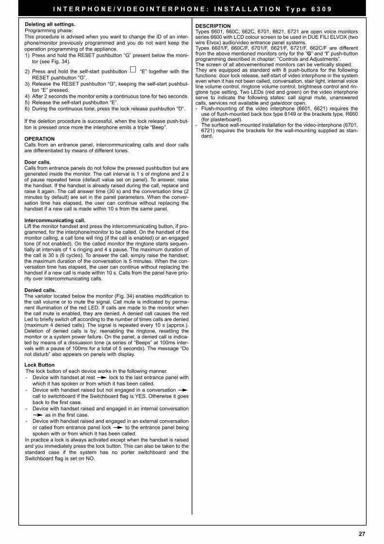
27
I N T E R P H O N E / V I D E O I N T E R P H O N E : I N S T A L L A T I O N T y p e 6 3 0 9
Deleting all settings.
Programming phase:
This procedure is advised when you want to change the ID of an inter-
phone/monitor previously programmed and you do not want keep the
operation programming of the appliance.
1) Press and hold the RESET pushbutton “G” present below the moni-
tor (see Fig. 34).
2) Press and hold the self-start pushbutton “E” together with the
RESET pushbutton “G”.
3) Release the RESET pushbutton “G”, keeping the self-start pushbut-
ton “E” pressed.
4) After 2 seconds the monitor emits a continuous tone for two seconds.
5) Release the self-start pushbutton “E”.
6) During the continuous tone, press the lock release pushbutton “D”.
If the deletion procedure is successful, when the lock release push-but-
ton is pressed once more the interphone emits a triple “Beep”.
OPERATIONCalls from an entrance panel, intercommunicating calls and door callsare differentiated by means of different tones.
Door calls.Calls from entrance panels do not follow the pressed pushbutton but aregenerated inside the monitor. The call interval is 1 s of ringtone and 2 sof pause repeated twice (default value set on panel). To answer, raisethe handset. If the handset is already raised during the call, replace andraise it again. The call answer time (30 s) and the conversation time (2minutes by default) are set in the panel parameters. When the conver-sation time has elapsed, the user can continue without replacing thehandset if a new call is made within 10 s from the same panel.
Intercommunicating call.Lift the monitor handset and press the intercommunicating button, if pro-grammed, for the interphone/monitor to be called. On the handset of themonitor calling, a call tone will ring (if the call is enabled) or an engagedtone (if not enabled). On the called monitor the ringtone starts sequen-tially at intervals of 1 s ringing and 4 s pause. The maximum duration ofthe call is 30 s (6 cycles). To answer the call, simply raise the handset;the maximum duration of the conversation is 5 minutes. When the con-versation time has elapsed, the user can continue without replacing thehandset if a new call is made within 10 s. Calls from the panel have prio-rity over intercommunicating calls.
Denied calls.The variator located below the monitor (Fig. 34) enables modification tothe call volume or to mute the signal. Call mute is indicated by perma-nent illumination of the red LED. If calls are made to the monitor whenthe call mute is enabled, they are denied. A denied call causes the redLed to briefly switch off according to the number of times calls are denied(maximum 4 denied calls). The signal is repeated every 10 s (approx.).Deletion of denied calls is by: reenabling the ringtone, resetting themonitor or a system power failure. On the panel, a denied call is indica-ted by means of a dissuasion tone (a series of “Beeps” at 100ms inter-vals with a pause of 100ms for a total of 5 seconds). The message “Donot disturb” also appears on panels with display.
Lock Button
The lock button of each device works in the following manner.
- Device with handset at rest lock to the last entrance panel with
which it has spoken or from which it has been called.
- Device with handset raised but not engaged in a conversation
call to switchboard if the Switchboard flag is YES. Otherwise it goes
back to the first case.
- Device with handset raised and engaged in an internal conversation
as in the first case.
- Device with handset raised and engaged in an external conversation
or called from entrance panel lock to the entrance panel being
spoken with or from which it has been called.
In practice a lock is always activated except when the handset is raised
and you immediately press the lock button. This can also be taken to the
standard case if the system has no porter switchboard and the
Switchboard flag is set on NO.
DESCRIPTIONTypes 6601, 660C, 662C, 6701, 6621, 6721 are open voice monitorsseries 6600 with LCD colour screen to be used in DUE FILI ELVOX (twowire Elvox) audio/video entrance panel systems.Types 6601/F, 660C/F, 6701/F, 6621/F, 6721/F, 662C/F are differentfrom the above mentioned monitors only for the “G” and “I” push-buttonprogramming described in chapter: “Controls and Adjustments”.The screen of all abovementioned monitors can be vertically sloped.They are equipped as standard with 8 push-buttons for the followingfunctions: door lock release, self-start of video interphone in the systemeven when it has not been called, conversation, stair light, internal voiceline volume control, ringtone volume control, brightness control and rin-gtone type setting. Two LEDs (red and green) on the video interphoneserve to indicate the following states: call signal mute, unansweredcalls, services not available and gate/door open. - Flush-mounting of the video interphone (6601, 6621) requires the
use of flush-mounted back box type 6149 or the brackets type. R660(for plasterboard).
- The surface wall-mounted installation for the video-interphone (6701,6721) requires the brackets for the wall-mounting supplied as stan-dard.
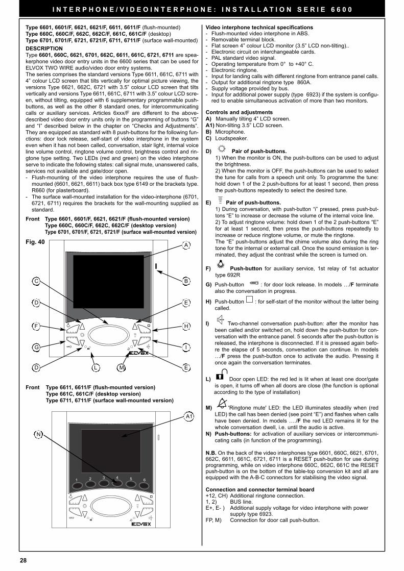
28
I N T E R P H O N E / V I D E O I N T E R P H O N E : I N S T A L L A T I O N S E R I E 6 6 0 0
DESCRIPTION
Type 6601, 660C, 6621, 6701, 662C, 6611, 661C, 6721, 6711 are spea-kerphone video door entry units in the 6600 series that can be used forELVOX TWO WIRE audio/video door entry systems.The series comprises the standard versions Type 6611, 661C, 6711 with4” colour LCD screen that tilts vertically for optimal picture viewing, theversions Type 6621, 662C, 6721 with 3.5” colour LCD screen that tiltsvertically and versions Type 6611, 661C, 6711 with 3.5” colour LCD scre-en, without tilting, equipped with 6 supplementary programmable push-buttons, as well as the other 8 standard ones, for intercommunicatingcalls or auxiliary services. Articles 6xxx/F are different to the above-described video door entry units only in the programming of buttons “G”and “I” described below in the chapter on “Checks and Adjustments”.They are equipped as standard with 8 push-buttons for the following fun-ctions: door lock release, self-start of video interphone in the systemeven when it has not been called, conversation, stair light, internal voiceline volume control, ringtone volume control, brightness control and rin-gtone type setting. Two LEDs (red and green) on the video interphoneserve to indicate the following states: call signal mute, unanswered calls,services not available and gate/door open. - Flush-mounting of the video interphone requires the use of flush-
mounted (6601, 6621, 6611) back box type 6149 or the brackets type.R660 (for plasterboard).
- The surface wall-mounted installation for the video-interphone (6701,6721, 6711) requires the brackets for the wall-mounting supplied asstandard.
Video interphone technical specifications- Flush-mounted video interphone in ABS.- Removable terminal block.- Flat screen 4” colour LCD monitor (3.5” LCD non-tilting)..- Electronic circuit on interchangeable cards.- PAL standard video signal.- Operating temperature from 0° to +40° C. - Electronic ringtone.- Input for landing calls with different ringtone from entrance panel calls.- Output for additional ringtone type 860A.- Supply voltage provided by bus.- Input for additional power supply (type 6923) if the system is configu-
red to enable simultaneous activation of more than two monitors.
Controls and adjustments
A) Manually tilting 4” LCD screen.
A1) Non-tilting 3.5” LCD screen.
B) Microphone.
C) Loudspeaker.
D) Pair of push-buttons.
1) When the monitor is ON, the push-buttons can be used to adjust
the brightness.
2) When the monitor is OFF, the push-buttons can be used to select
the tune for calls from a speech unit only. To programme the tune:
hold down 1 of the 2 push-buttons for at least 1 second, then press
the push-buttons repeatedly to select the desired tune.
E) Pair of push-buttons.
1) During conversation, with push-button “i” pressed, press push-but-
tons “E” to increase or decrease the volume of the internal voice line.
2) To adjust ringtone volume: hold down 1 of the 2 push-buttons “E”
for at least 1 second, then press the push-buttons repeatedly to
increase or reduce ringtone volume, or mute the ringtone.
The “E” push-buttons adjust the chime volume also during the ring
tone for the internal or external call. Once the sound emission is ter-
minated, they adjust the contrast while the screen is turned on.
F) Push-button for auxiliary service, 1st relay of 1st actuator
type 692R
G) Push-button : for door lock release. In models …/F terminate
also the conversation in progress.
H) Push-button : for self-start of the monitor without the latter being
called.
I) Two-channel conversation push-button: after the monitor has
been called and/or switched on, hold down the push-button for con-
versation with the entrance panel. 5 seconds after the push-button is
released, the interphone is disconnected. If it is pressed again befo-
re the elapse of 5 seconds, conversation can continue. In models
…/F press the push-button once to activate the audio. Pressing it
once again the conversation terminates.
L) Door open LED: the red led is lit when at least one door/gate
is open, it turns off when all doors are close (the function is optional
according to the type of installation)
M) 'Ringtone mute' LED: the LED illuminates steadily when (red
LED) the call has been denied (see point “E”) and flashes when calls
have been denied. In models …./F the red LED remains lit for the
whole conversation dwell, i.e. until the audio is active.
N) Push-buttons: for activation of auxiliary services or intercommuni-
cating calls (in function of the programming).
N.B. On the back of the video interphones type 6601, 660C, 6621, 6701,662C, 6611, 661C, 6721, 6711 is a RESET push-button for use duringprogramming, while on video interphone 660C, 662C, 661C the RESETpush-button is on the bottom of the table-top conversion kit and all areequipped with the A-B-C connectors for stabilising the video signal.
Connection and connector terminal board+12, CH) Additional ringtone connection.1, 2) BUS line.E+, E- ) Additional supply voltage for video interphone with power
supply type 6923.FP, M) Connection for door call push-button.
A
B
E
H
I
D E
D
F
G
C
L M
Fig. 40
A1
N
Front Type 6601, 6601/F, 6621, 6621/F (flush-mounted version)
Type 660C, 660C/F, 662C, 662C/F (desktop version)
Type 6701, 6701/F, 6721, 6721/F (surface wall-mounted version)
Front Type 6611, 6611/F (flush-mounted version)
Type 661C, 661C/F (desktop version)
Type 6711, 6711/F (surface wall-mounted version)
Type 6601, 6601/F, 6621, 6621/F, 6611, 6611/F (flush-mounted)
Type 660C, 660C/F, 662C, 662C/F, 661C, 661C/F (desktop)
Type 6701, 6701/F, 6721, 6721/F, 6711, 6711/F (surface wall-mounted)
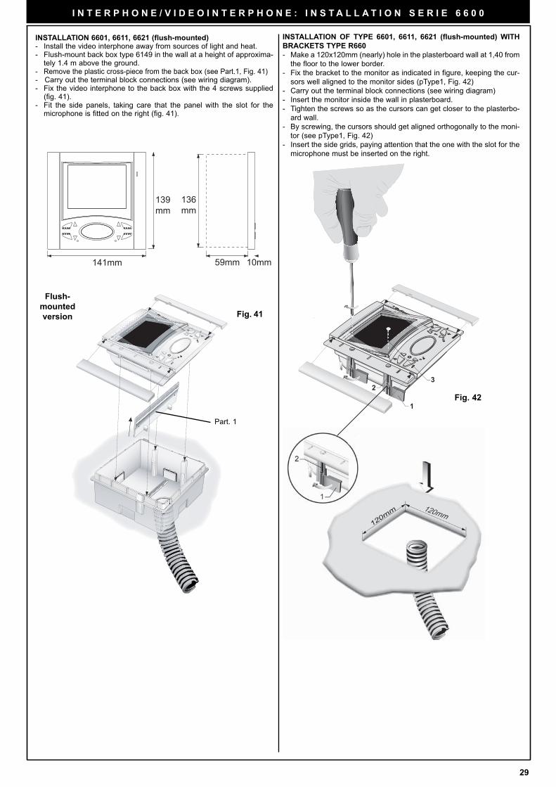
29
I N T E R P H O N E / V I D E O I N T E R P H O N E : I N S T A L L A T I O N S E R I E 6 6 0 0
32
1
INSTALLATION OF TYPE 6601, 6611, 6621 (flush-mounted) WITH
BRACKETS TYPE R660
- Make a 120x120mm (nearly) hole in the plasterboard wall at 1,40 from
the floor to the lower border.
- Fix the bracket to the monitor as indicated in figure, keeping the cur-
sors well aligned to the monitor sides (pType1, Fig. 42)
- Carry out the terminal block connections (see wiring diagram)
- Insert the monitor inside the wall in plasterboard.
- Tighten the screws so as the cursors can get closer to the plasterbo-
ard wall.
- By screwing, the cursors should get aligned orthogonally to the moni-
tor (see pType1, Fig. 42)
- Insert the side grids, paying attention that the one with the slot for the
microphone must be inserted on the right.
Fig. 42
INSTALLATION 6601, 6611, 6621 (flush-mounted)- Install the video interphone away from sources of light and heat.- Flush-mount back box type 6149 in the wall at a height of approxima-
tely 1.4 m above the ground.- Remove the plastic cross-piece from the back box (see Part.1, Fig. 41)- Carry out the terminal block connections (see wiring diagram).- Fix the video interphone to the back box with the 4 screws supplied
(fig. 41).- Fit the side panels, taking care that the panel with the slot for the
microphone is fitted on the right (fig. 41).
Fig. 41
Flush-
mounted
version
59mm 10mm141mm
139mm
136mm
Part. 1
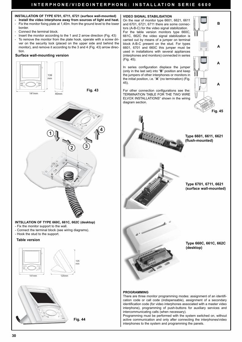
30
I N T E R P H O N E / V I D E O I N T E R P H O N E : I N S T A L L A T I O N S E R I E 6 6 0 0
PROGRAMMING
There are three monitor programming modes: assignment of an identifi-
cation code or call code (indispensable), assignment of a secondary
identification code (for video interphones associated with a master video
interphone), programming of push-buttons for auxiliary services and
intercommunicating calls (when necessary).
Programming must be performed with the system switched on, without
active communication and only after connecting the interphones/video
interphones to the system and programming the panels.
Fig. 45
B
A
A
A
VIDEO SIGNAL STABILISATION
On the rear of monitor type 6601, 6621, 6611
and 6701, 6721, 6711 there are some connec-
tors (A-B-C) for the video signal stabilization.
For the table version monitors type 660C,
661C, 662C the video signal stabilization is
carried out by means of a jumper on terminal
block A-B-C present on the stud. For types
6601, 6701 and 660C this jumper must be
used in installations with several appliances
(interphones and monitors) connected in series
(Fig. 45).
In series configuration displace the jumper
(only in the last set) into “B” position and keep
the jumpers of other interphones or monitors in
the initial position, i.e. “A” (no termination) (Fig.
45).
For other connection configurations see the:
TERMINATION TABLE FOR THE TWO WIRE
ELVOX INSTALLATIONS” shown in the wiring
diagram section.
Type 6601, 6611, 6621
(flush-mounted)
Type 6701, 6711, 6621
(surface wall-mounted)
Type 660C, 661C, 662C
(desktop)
Table version
Surface wall-mounting version
40mm141mm
139mm
INTSLLATION OF TYPE 660C, 661C, 662C (desktop)
- Fix the monitor support to the wall.
- Connect the terminal block (see wiring diagrams).
- Hook the stud to the support.
INSTALLATION OF TYPE 6701, 6711, 6721 (surface wall-mounted)
- Install the video interphone away from sources of light and heat.
- Fix the monitor fixing plate at 1,40m. from the ground level to the lower
border.
- Connect the terminal block.
- Insert the monitor according to the 1 and 2 arrow direction (Fig. 43)
- To remove the monitor from the plate hook, operate with a screw dri-
ver on the security lock (placed on the upper side and behind the
monitor), and remove it according to the 3 and 4 (Fig. 43) arrow direc-
tion.
141mm 125mm
125mm
1
2 3
4
Fig. 43
Fig. 44
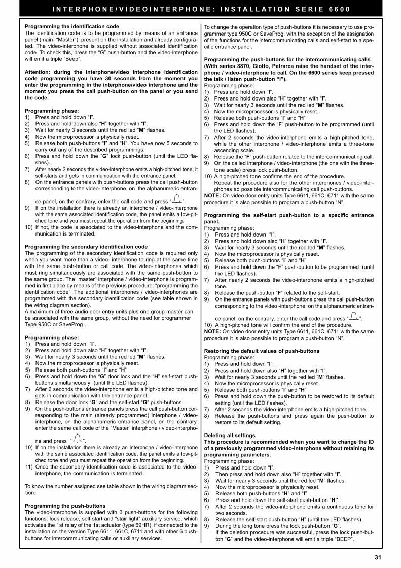
31
I N T E R P H O N E / V I D E O I N T E R P H O N E : I N S T A L L A T I O N S E R I E 6 6 0 0
To change the operation type of push-buttons it is necessary to use pro-
grammer type 950C or SaveProg, with the exception of the assignation
of the functions for the intercommunicating calls and self-start to a spe-
cific entrance panel.
Programming the push-buttons for the intercommunicating calls
(With series 8870, Giotto, Petrarca raise the handset of the inter-
phone / video-interphone to call. On the 6600 series keep pressed
the talk / listen push-button “I”).
Programming phase:
1) Press and hold down “I”.
2) Press and hold down also “H” together with “I”.
3) Wait for nearly 3 seconds until the red led “M” flashes.
4) Now the microprocessor is physically reset.
5) Release both push-buttons “I” and “H”
6) Press and hold down the “F” push-button to be programmed (until
the LED flashes).
7) After 2 seconds the video-interphone emits a high-pitched tone,
while the other interphone / video-interphone emits a three-tone
ascending scale.
8) Release the “F” push-button related to the intercommunicating call.
9) On the called interphone / video-interphone (the one with the three-
tone scale) press lock push-button.
10) A high-pitched tone confirms the end of the procedure.
Repeat the procedure also for the other interphones / video-inter-
phones ad possible intercommunicating call push-buttons.
NOTE: On video door entry units Type 6611, 661C, 6711 with the same
procedure it is also possible to program a push-button “N”.
Programming the self-start push-button to a specific entrance
panel.
Programming phase:
1) Press and hold down “I”.
2) Press and hold down also “H” together with “I”.
3) Wait for nearly 3 seconds until the red led “M” flashes.
4) Now the microprocessor is physically reset.
5) Release both push-buttons “I” and “H”
6) Press and hold down the “F” push-button to be programmed (until
the LED flashes).
7) After nearly 2 seconds the video-interphone emits a high-pitched
tone.
8) Release the push-button “F” related to the self-start.
9) On the entrance panels with push-buttons press the call push-button
corresponding to the video -interphone; on the alphanumeric entran-
ce panel, on the contrary, enter the call code and press “ ”.
10) A high-pitched tone will confirm the end of the procedure.
NOTE: On video door entry units Type 6611, 661C, 6711 with the same
procedure it is also possible to program a push-button “N”.
Restoring the default values of push-buttons
Programming phase:
1) Press and hold down “I”.
2) Press and hold down also “H” together with “I”.
3) Wait for nearly 3 seconds until the red led “M” flashes.
4) Now the microprocessor is physically reset.
5) Release both push-buttons “I” and “H”
6) Press and hold down the push-button to be restored to its default
setting (until the LED flashes).
7) After 2 seconds the video-interphone emits a high-pitched tone.
8) Release the push-buttons and press again the push-button to
restore to its default setting.
Deleting all settings
This procedure is recommended when you want to change the ID
of a previously programmed video-interphone without retaining its
programming parameters.
Programming phase:
1) Press and hold down “I”.
2) Then press and hold down also “H” together with “I”.
3) Wait for nearly 3 seconds until the red led “M” flashes.
4) Now the microprocessor is physically reset.
5) Release both push-buttons “H” and “I”
6) Press and hold down the self-start push-button “H”.
7) After 2 seconds the video-interphone emits a continuous tone for
two seconds.
8) Release the self-start push-button “H” (until the LED flashes).
9) During the long tone press the lock push-button “G”.
If the deletion procedure was successful, press the lock push-but-
ton “G” and the video-interphone will emit a triple “BEEP”.
Programming the identification code
The identification code is to be programmed by means of an entrance
panel (main- “Master”), present on the installation and already configura-
ted. The video-interphone is supplied without associated identification
code. To check this, press the “G” push-button and the video-interphone
will emit a triple “Beep”.
Attention: during the interphone/video interphone identification
code programming you have 30 seconds from the moment you
enter the programming in the interphone/video interphone and the
moment you press the call push-button on the panel or you send
the code.
Programming phase:
1) Press and hold down “I”.
2) Press and hold down also “H” together with “I”.
3) Wait for nearly 3 seconds until the red led “M” flashes.
4) Now the microprocessor is physically reset.
5) Release both push-buttons “I” and “H”. You have now 5 seconds to
carry out any of the described programmings.
6) Press and hold down the “G” lock push-button (until the LED fla-
shes).
7) After nearly 2 seconds the video-interphone emits a high-pitched tone, it
self-starts and gets in communication with the entrance panel.
8) On the entrance panels with push-buttons press the call push-button
corresponding to the video-interphone, on the alphanumeric entran-
ce panel, on the contrary, enter the call code and press “ ”.
9) If on the installation there is already an interphone / video-interphone
with the same associated identification code, the panel emits a low-pit-
ched tone and you must repeat the operation from the beginning.
10) If not, the code is associated to the video-interphone and the com-
munication is terminated.
Programming the secondary identification code
The programming of the secondary identification code is required only
when you want more than a video- interphone to ring at the same time
with the same push-button or call code. The video-interphones which
must ring simultaneously are associated with the same push-button to
the same group. The “master” interphone / video-interphone is program-
med in first place by means of the previous procedure: “programming the
identification code”. The additional interphones / video-interphones are
programmed with the secondary identification code (see table shown in
the wiring diagram section).
A maximum of three audio door entry units plus one group master can
be associated with the same group, without the need for programmer
Type 950C or SaveProg .
Programming phase:
1) Press and hold down “I”.
2) Press and hold down also “H” together with “I”.
3) Wait for nearly 3 seconds until the red led “M” flashes.
4) Now the microprocessor is physically reset.
5) Release both push-buttons “I” and “H”
6) Press and hold down the “G” door lock and the “H” self-start push-
buttons simultaneously (until the LED flashes).
7) After 2 seconds the video-interphone emits a high-pitched tone and
gets in communication with the entrance panel.
8) Release the door lock “G” and the self-start “G” push-buttons.
9) On the push-buttons entrance panels press the call push-button cor-
responding to the main (already programmed) interphone / video-
interphone, on the alphanumeric entrance panel, on the contrary,
enter the same call code of the “Master” interphone / video-interpho-
ne and press “ ”.
10) If on the installation there is already an interphone / video-interphone
with the same associated identification code, the panel emits a low-pit-
ched tone and you must repeat the operation from the beginning.
11) Once the secondary identification code is associated to the video-
interphone, the communication is terminated.
To know the number assigned see table shown in the wiring diagram sec-
tion.
Programming the push-buttons
The video-interphone is supplied with 3 push-buttons for the following
functions: lock release, self-start and “stair light” auxiliary service, which
activates the 1st relay of the 1st actuator (type 69HR), if connected to the
installation on the version Type 6611, 661C, 6711 and with other 6 push-
buttons for intercommunicating calls or auxiliary services.
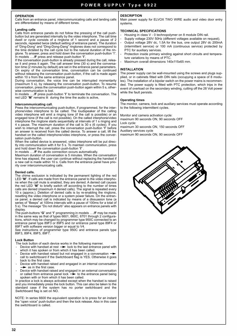
32
P O W E R S U P P L Y T y p e 6 9 2 2
DESCRIPTION
Main power supply for ELVOX TWO WIRE audio and video door entry
systems.
TECHNICAL SPECIFICATIONS
- Housing in class V - 0 technopolymer on 8 module DIN rail.
- Supply voltage 230V 50Hz (different voltages available on request).
- Output voltage 28V dc, 1.5A for the bus, one output 28V dc 200mA
(intermittent service) or 100 mA (continuous service) protected by
PTC for auxiliary services.
- Protection inside primary winding against short circuits and tempera-
ture variations by means of PTC.
- Maximum overall dimensions 140x115x65 mm.
INSTALLATION
The power supply can be wall-mounted using the screws and plugs sup-
plied, or in cabinets fitted with DIN rails (occupying a space of 8 modu-
les). The installation of a bipolar switch on the power mains is recommen-
ded. The power supply is fitted with PTC protection, which trips in the
event of overload on the secondary winding, cutting off the 28 Volt power
while the fault persists.
Operating times
The monitor, camera, lock and auxiliary services must operate according
to the following intermittent cycles.
Monitor and camera activation cycle:
maximum 90 seconds ON, 90 seconds OFF
Lock cycle:
maximum 30 seconds ON, 150 seconds OFF
Auxiliary services cycle
maximum 90 seconds ON, 90 seconds OFF
OPERATIONCalls from an entrance panel, intercommunicating calls and landing callsare differentiated by means of different tones.
Landing callsCalls from entrance panels do not follow the pressing of the call push-button but are generated internally by the video interphone. The call timedwell or cycle consists of a ringtone of 1 second and a pause of 2seconds, repeated twice (default setting of entrance panel). The durationof “Ding-Dong” and “Ding-Dong-Dang” ringtones does not correspond tothe time dictated by the call cycle but to the natural duration of the rin-gtone. To answer, press and hold down the conversation push-button “I”. In models …./F press and release push-button “I”.If the conversation push-button is already pressed during the call, relea-se it and press it again. The call answer time (30 s) and the conversa-tion time (2 minutes by default) are set in the entrance panel parameters.On expiry of the conversation time, conversation can be continuedwithout releasing the conversation push-button, if the call is made againwithin 10 s from the same entrance panel. During conversation, the voice line can be interrupted momentarily(maximum 5 s), by releasing the conversation push-button. To resumeconversation, press the conversation push-button again within 5 s, other-wise communication is lost. In models …./F press push-button “I” to terminate the conversation. Thered LED “M” remains lit during the time the audio is active,
Intercommunicating call.Press the intercommunicating push-button, if programmed, for the inter-phone/video interphone to be called. The loudspeaker of the callingvideo interphone will emit a ringing tone (if the call is possible) or anengaged tone (if the call is not possible). On the called interphone/videointerphone the ringtone starts sequentially at intervals of 1 s ringing and4 s pause. The maximum duration of the call is 30 s (6 cycles). If youwish to interrupt the call, press the conversation push-button “I” beforean answer is received from the called device. To answer a call, lift thehandset on the called interphone/video interphone, or press the conver-sation push-button. When the called device is answered, video interphone will be put direc-tly into communication with it for 5 s. To maintain communication, pressand hold down the conversation push-button “I” . In models …./F the audio connection occurs automatically.Maximum duration of conversation is 5 minutes. When the conversationtime has elapsed, the user can continue without replacing the handset ifa new call is made within 10 s. Calls from the entrance panel have prio-rity over intercommunicating calls.
Denied calls.The chime exclusion is indicated by the permanent lighting of the redLED “M”. If calls are made from the entrance panel to the video interpho-ne when the call mute is enabled, they are denied. A denied call causesthe red LED “M” to briefly switch off according to the number of timescalls are denied (maximum 4 denied calls). The signal is repeated every10 s (approx.). Deletion of denied calls is by re-enabling the ringtone,resetting the video interphone or a system power failure. On the entran-ce panel, a denied call is indicated by means of a dissuasion tone (aseries of “Beeps” at 100ms intervals with a pause of 100ms for a total of5 s). The message “Do not disturb” also appears on entrance panels withdisplay. The push-buttons “G” and “I” programming in models …./F may be madein the same way as that of types 6601, 660C, 6701 through 2 configura-tions, which may be changed by programmer type 950C connected to anentrance panel type 89F3 or 89F5 and /or entrance panel type 89F4 or89F7 with software version bigger or equal to V4.See instructions of programmer type 950C and entrance panels type89F3, 89F4, 89F5, 89F7.
Lock ButtonThe lock button of each device works in the following manner.- Device with handset at rest lock to the last entrance panel with
which it has spoken or from which it has been called.- Device with handset raised but not engaged in a conversation
call to switchboard if the Switchboard flag is YES. Otherwise it goesback to the first case.
- Device with handset raised and engaged in an internal conversationas in the first case.
- Device with handset raised and engaged in an external conversationor called from entrance panel lock to the entrance panel beingspoken with or from which it has been called.
In practice a lock is always activated except when the handset is raisedand you immediately press the lock button. This can also be taken to thestandard case if the system has no porter switchboard and theSwitchboard flag is set on NO.
NOTE: In series 6600 the equivalent operation is to press for an instantthe “open voice” push-button and then the lock release. Also in this casethe switchboard is called.
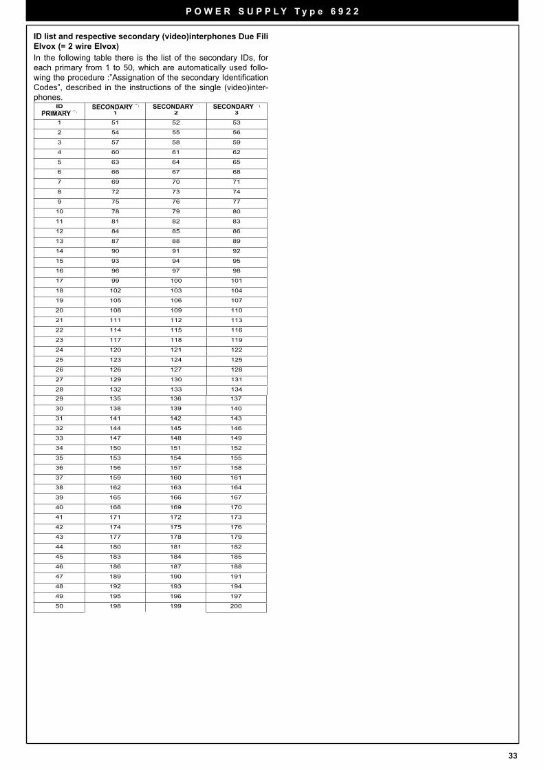
33
ID list and respective secondary (video)interphones Due Fili
Elvox (= 2 wire Elvox)
In the following table there is the list of the secondary IDs, for
each primary from 1 to 50, which are automatically used follo-
wing the procedure :”Assignation of the secondary Identification
Codes”, described in the instructions of the single (video)inter-
phones.ID
PRIMARIOSECONDARIO
1SECONDARIO
2SECONDARIO
3
1 51 52 53
2 54 55 56
3 57 58 59
4 60 61 62
5 63 64 65
6 66 67 68
7 69 70 71
8 72 73 74
9 75 76 77
10 78 79 80
11 81 82 83
12 84 85 86
13 87 88 89
14 90 91 92
15 93 94 95
16 96 97 98
17 99 100 101
18 102 103 104
19 105 106 107
20 108 109 110
21 111 112 113
22 114 115 116
23 117 118 119
24 120 121 122
25 123 124 125
26 126 127 128
27 129 130 131
28 132 133 134
29 135 136 137
30 138 139 140
31 141 142 143
32 144 145 146
33 147 148 149
34 150 151 152
35 153 154 155
36 156 157 158
37 159 160 161
38 162 163 164
39 165 166 167
40 168 169 170
41 171 172 173
42 174 175 176
43 177 178 179
44 180 181 182
45 183 184 185
46 186 187 188
47 189 190 191
48 192 193 194
49 195 196 197
50 198 199 200
PRIMARYSECONDARY SECONDARY SECONDARY
P O W E R S U P P L Y T y p e 6 9 2 2
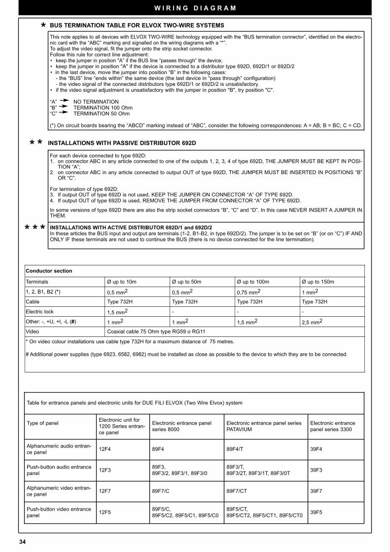
34
W I R I N G D I A G R A M
Table for entrance panels and electronic units for DUE FILI ELVOX (Two Wire Elvox) system
Type of panelElectronic unit for
1200 Series entran-
ce panel
Electronic entrance panel
series 8000
Electronic entrance panel series
PATAVIUM
Electronic entrance
panel series 3300
Alphanumeric audio entran-
ce panel12F4 89F4 89F4/T 39F4
Push-button audio entrance
panel12F3
89F3,
89F3/2, 89F3/1, 89F3/0
89F3/T,
89F3/2T, 89F3/1T, 89F3/0T39F3
Alphanumeric video entran-
ce panel12F7 89F7/C 89F7/CT 39F7
Push-button video entrance
panel12F5
89F5/C,
89F5/C2, 89F5/C1, 89F5/C0
89F5/CT,
89F5/CT2, 89F5/CT1, 89F5/CT039F5
Conductor section
Terminals Ø up to 10m Ø up to 50m Ø up to 100m Ø up to 150m
1, 2, B1, B2 (*) 0,5 mm2 0,5 mm2 0,75 mm2 1 mm2
Cable Type 732H Type 732H Type 732H Type 732H
Electric lock 1,5 mm2 - - -
Other: -, +U, +I, -L (#) 1 mm2 1 mm2 1,5 mm2 2,5 mm2
Video Coaxial cable 75 Ohm type RG59 o RG11
* On video colour installations use cable type 732H for a maximum distance of 75 metres.
# Additional power supplies (type 6923, 6582, 6982) must be installed as close as possible to the device to which they are to be connected.
INSTALLATIONS WITH PASSIVE DISTRIBUTOR 692D
BUS TERMINATION TABLE FOR ELVOX TWO-WIRE SYSTEMS
This note applies to all devices with ELVOX TWO-WIRE technology equipped with the “BUS termination connector”, identified on the electro-nic card with the “ABC” marking and signalled on the wiring diagrams with a “*”.To adjust the video signal, fit the jumper onto the strip socket connector.Follow this rule for correct line adjustment:• keep the jumper in position "A” if the BUS line “passes through” the device;• keep the jumper in position "A" if the device is connected to a distributor type 692D, 692D/1 or 692D/2• in the last device, move the jumper into position “B” in the following cases:
- the “BUS” line “ends within” the same device (the last device in “pass through” configuration) - the video signal of the connected distributors type 692D/1 or 692D/2 is unsatisfactory.
• if the video signal adjustment is unsatisfactory with the jumper in position "B", try position "C".
“A” NO TERMINATION“B” TERMINATION 100 Ohm“C” TERMINATION 50 Ohm
(*) On circuit boards bearing the “ABCD” marking instead of “ABC”, consider the following correspondences: A = AB; B = BC; C = CD.
For each device connected to type 692D:1. on connector ABC in any article connected to one of the outputs 1, 2, 3, 4 of type 692D, THE JUMPER MUST BE KEPT IN POSI-
TION “A”; 2. on connector ABC in any article connected to output OUT of type 692D, THE JUMPER MUST BE INSERTED IN POSITIONS “B”
OR “C”.
For termination of type 692D:3. If output OUT of type 692D is not used, KEEP THE JUMPER ON CONNECTOR “A” OF TYPE 692D. 4. If output OUT of type 692D is used, REMOVE THE JUMPER FROM CONNECTOR “A” OF TYPE 692D.
In some versions of type 692D there are also the strip socket connectors “B”, “C” and “D”. In this case NEVER INSERT A JUMPER INTHEM.
INSTALLATIONS WITH ACTIVE DISTRIBUTOR 692D/1 and 692D/2In these articles the BUS input and output are terminals (1-2, B1-B2, in type 692D/2). The jumper is to be set on “B” (or on “C”) IF ANDONLY IF these terminals are not used to continue the BUS (there is no device connected for the line termination).
*
**
***
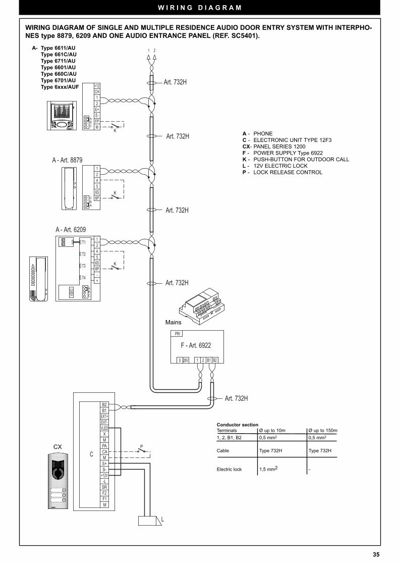
35
P
L
C
K
K
K
6PT3
VIDEO B
C
+-T4
A
12T1
6S5T2 4
6P
12
6S54
F - Art. 6922
Art. 732H
Art. 732H
Art. 732H
A - Art. 6209
A - Art. 8879
A - Art. 6601/AU Art. 660C/AU Art. 6701/AU Art. 6611/AU Art. 6711/AU Art. 661C/AU
Art. 732H
Art. 732H
1 2 B1 B2
B1
EXT-EXT+
B2
X
PAM
MS+
+12VS-
CA
SR
F1F2
M
-L
VLED
PRI
0 28V
21
+12CH
M
2
E-FP
E+
1
C
AB
BA
C
WIRING DIAGRAM OF SINGLE AND MULTIPLE RESIDENCE AUDIO DOOR ENTRY SYSTEM WITH INTERPHO-
NES type 8879, 6209 AND ONE AUDIO ENTRANCE PANEL (REF. SC5401).
A - PHONE
C - ELECTRONIC UNIT TYPE 12F3
CX- PANEL SERIES 1200
F - POWER SUPPLY Type 6922
K - PUSH-BUTTON FOR OUTDOOR CALL
L - 12V ELECTRIC LOCK
P - LOCK RELEASE CONTROL
Conductor section
Terminals Ø up to 10m Ø up to 150m
1, 2, B1, B2 0,5 mm2 0,5 mm2
Cable Type 732H Type 732H
Electric lock 1,5 mm2 -
Mains
W I R I N G D I A G R A M
CX
A- Type 6611/AU
Type 661C/AU
Type 6711/AU
Type 6601/AU
Type 660C/AU
Type 6701/AU
Type 6xxx/AUF
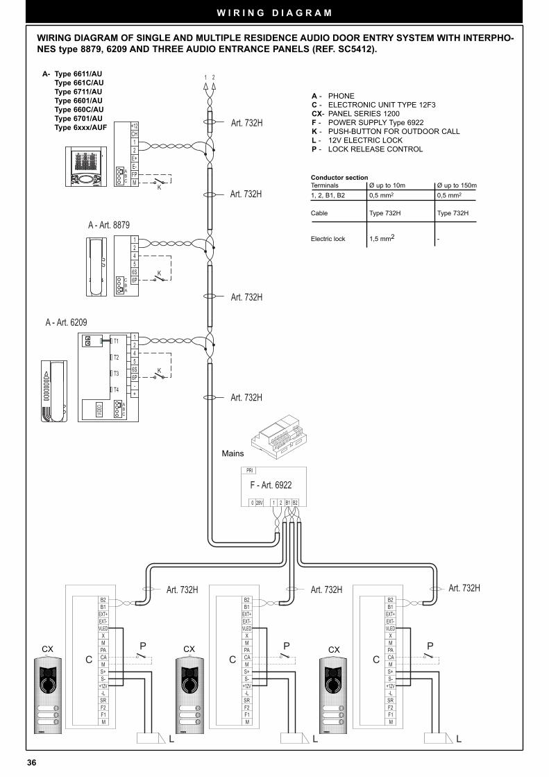
36
W I R I N G D I A G R A M
P
LL
PP
L
C C CC C C
F - Art. 6922
Art. 732HArt. 732HArt. 732H
Art. 732H
Art. 732H
K
K
K
6PT3
VIDEO B
C
+-T4
A
12T1
6S5T2 4
6P
12
6S54
21
+12CH
M
2
E-FP
E+
1
C
AB
BA
C
0 28V B11 2 B2
PRI
B1
EXT-EXT+
B2
X
PAM
MS+
+12VS-
CA
SR
F1F2
M
-L
VLED VLED
-L
M
F2F1
SR
CA
S-+12V
S+M
MPA
X
B2
EXT+EXT-
B1 B1
EXT-EXT+
B2
X
PAM
MS+
+12VS-
CA
SR
F1F2
M
-L
VLED
Art. 732H
A - Art. 6209
Art. 732H
A - Art. 8879
A - Art. 6601/AU Art. 660C/AU Art. 6701/AU Art. 6611/AU Art. 6711/AU Art. 661C/AU
WIRING DIAGRAM OF SINGLE AND MULTIPLE RESIDENCE AUDIO DOOR ENTRY SYSTEM WITH INTERPHO-
NES type 8879, 6209 AND THREE AUDIO ENTRANCE PANELS (REF. SC5412).
Conductor section
Terminals Ø up to 10m Ø up to 150m
1, 2, B1, B2 0,5 mm2 0,5 mm2
Cable Type 732H Type 732H
Electric lock 1,5 mm2 -
Mains
A - PHONE
C - ELECTRONIC UNIT TYPE 12F3
CX- PANEL SERIES 1200
F - POWER SUPPLY Type 6922
K - PUSH-BUTTON FOR OUTDOOR CALL
L - 12V ELECTRIC LOCK
P - LOCK RELEASE CONTROL
CX CX CX
A- Type 6611/AU
Type 661C/AU
Type 6711/AU
Type 6601/AU
Type 660C/AU
Type 6701/AU
Type 6xxx/AUF
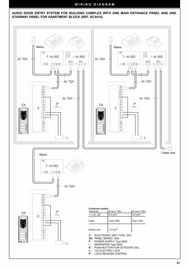
37
CP
L L
P
P
L
C
C
C C
C
Art. 732H
Art. 732HArt. 732H
Art. 732HArt. 732H
BA
CD D
C
AB
PRI
B221 B128V0
VLED
-L
M
F2F1
SR
CA
S-+12V
S+M
MPA
X
B2
EXT+EXT-
B1
BUS D1 2
PRI
B221 B128V0BUS P2 11 2
21 1 2
21 12BUS P
0 28V B11 2 B2
PRI
21BUS D
21
B1
EXT-EXT+
B2
X
PAM
MS+
+12VS-
CA
SR
F1F2
M
-L
VLED
B1
EXT-EXT+
B2
X
PAM
MS+
+12VS-
CA
SR
F1F2
M
-L
VLED
F - Art. 6922
I - Art. 692S I - Art. 692SF - Art. 6922F - Art. 6922
Art. 732HArt. 732H
W I R I N G D I A G R A M
AUDIO DOOR ENTRY SYSTEM FOR BUILDING COMPLEX WITH ONE MAIN ENTRANCE PANEL AND ONE
STAIRWAY PANEL FOR APARTMENT BLOCK (REF. SC5414).
Conductor section
Terminals Ø up to 10m Ø up to 150m
1, 2, B1, B2 0.5 mm2 0.5 mm2
Cable Type 732H Type 732H
Electric lock 1,5 mm2 -
C - ELECTRONIC UNIT TYPE 12F3
CX- PANEL SERIES 1200
F - POWER SUPPLY Type 6922
I - SEPARATOR Type 692S
K - PUSH-BUTTON FOR OUTDOOR CALL
L - 12V ELECTRIC LOCK
P - LOCK RELEASE CONTROL
Mains
MainsMains
Cable riser
CXCX
CX
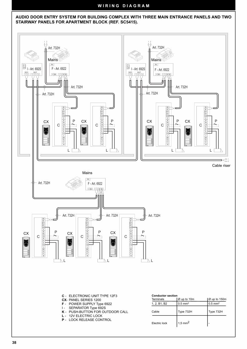
38
W I R I N G D I A G R A M
L
PP
L
C CCC
L
P P
L
PC
P
LL
P
L
C CC C C
C CCC
DC
ABB
A
CD
PRI
B221 B128V0
1 2
21 12BUS P
0 28V B11 2 B2
PRI
21BUS D
B1
EXT-EXT+
B2
X
PAM
MS+
+12VS-
CA
SR
F1F2
M
-L
VLED VLED
-L
M
F2F1
SR
CA
S-+12V
S+M
MPA
X
B2
EXT+EXT-
B1
12
B1
EXT-EXT+
B2
X
PAM
MS+
+12VS-
CA
SR
F1F2
M
-L
VLEDVLED
-L
M
F2F1
SR
CA
S-+12V
S+M
MPA
X
B2
EXT+EXT-
B1
BUS D1 2
PRI
B221 B128V0BUS P2 11 2
21
B1
EXT-EXT+
B2
X
PAM
MS+
+12VS-
CA
SR
F1F2
M
-L
VLED VLED
-L
M
F2F1
SR
CA
S-+12V
S+M
MPA
X
B2
EXT+EXT-
B1 B1
EXT-EXT+
B2
X
PAM
MS+
+12VS-
CA
SR
F1F2
M
-L
VLED
F - Art. 6922
Art. 732HArt. 732H
F - Art. 6922
Art. 732HArt. 732HArt. 732H
Art. 732H
Art. 732H
Art. 732H
Art. 732H
Art. 732H
I - Art. 692S I - Art. 692S
F - Art. 6922
AUDIO DOOR ENTRY SYSTEM FOR BUILDING COMPLEX WITH THREE MAIN ENTRANCE PANELS AND TWO
STAIRWAY PANELS FOR APARTMENT BLOCK (REF. SC5415).
C - ELECTRONIC UNIT TYPE 12F3
CX- PANEL SERIES 1200
F - POWER SUPPLY Type 6922
I - SEPARATOR Type 692S
K - PUSH-BUTTON FOR OUTDOOR CALL
L - 12V ELECTRIC LOCK
P - LOCK RELEASE CONTROL
Conductor section
Terminals Ø up to 10m Ø up to 150m
1, 2, B1, B2 0.5 mm2 0.5 mm2
Cable Type 732H Type 732H
Electric lock 1,5 mm2 -
Mains
Mains Mains
Cable riser
CX CXCXCX
CXCXCX
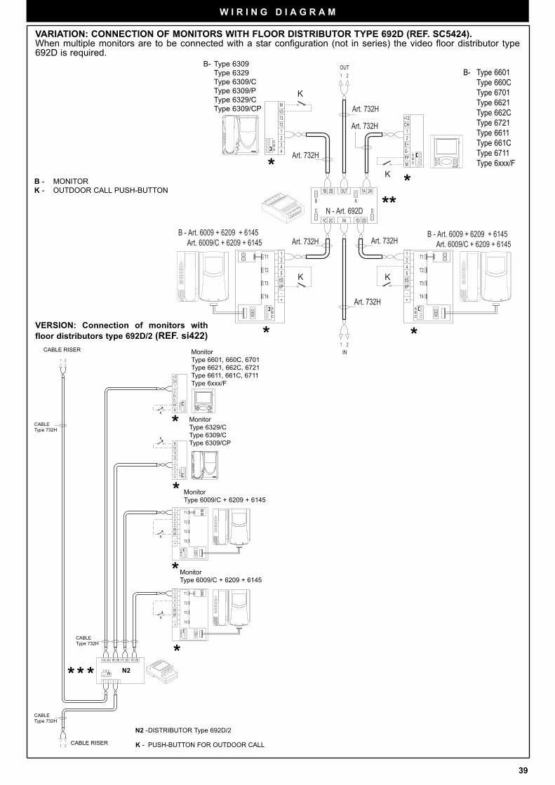
39
W I R I N G D I A G R A M
IN
OUT
C
AB
VIDEOB
A
VIDEO
C
K
N - Art. 692D
B - Art. 6009 + 6209 + 6145 Art. 6009/C + 6209 + 6145
Art. 732H
B - Art. 6309 Art. 6309/C
B - Art. 6601 Art. 6611 Art. 660C Art. 661C Art. 6701 Art. 6711
Art. 732H
K
K
B - Art. 6009 + 6209 + 6145 Art. 6009/C + 6209 + 6145
K
Art. 6309/P Art. 6309/CP
1B OUT 1A2B 2A
2D2C 1DIN1C
AB
C D
13
1
32
12
4
V3M
21
1 2
+12CH
M
2
E-FP
E+
1
12
54
6P
+-
6S
T1
T2
T4
T3
BC
A
T3
T4
T2
T1
6S
-+
6P
45
21
Art. 732H
Art. 732H
Art. 732H
Art. 732H A
CB
**
**
**VID
EOBA
C
AB
1D 2D
1 2
21
+12CH
2E+
1
M
E-FP B
A
C
MV3
4
12
23
1
13
C
21 12
2A 1B1A 2B 2C1C
C
AB
VIDEO
K
K
K
K
T3
T4
T2
T1
6S
-+
6P
45
21
A
CB
12
54
6P
+-
6S
T1
T2
T4
T3
Monitor
Type 6329/C
Type 6309/C
Type 6309/CP
Monitor
Type 6009/C + 6209 + 6145
Monitor
Type 6009/C + 6209 + 6145
CABLE RISER
CABLE RISER
VERSION: Connection of monitors with
floor distributors type 692D/2 (REF. si422)
N2
CABLE
Type 732H
CABLE
Type 732H
CABLE
Type 732H
***
*
*
*
*
VARIATION: CONNECTION OF MONITORS WITH FLOOR DISTRIBUTOR TYPE 692D (REF. SC5424).When multiple monitors are to be connected with a star configuration (not in series) the video floor distributor type692D is required.
B - MONITOR
K - OUTDOOR CALL PUSH-BUTTON
K - PUSH-BUTTON FOR OUTDOOR CALL
N2 -DISTRIBUTOR Type 692D/2
B- Type 6309
Type 6329
Type 6309/C
Type 6309/P
Type 6329/C
Type 6309/CP
B- Type 6601
Type 660C
Type 6701
Type 6621
Type 662C
Type 6721
Type 6611
Type 661C
Type 6711
Type 6xxx/F
Monitor
Type 6601, 660C, 6701
Type 6621, 662C, 6721
Type 6611, 661C, 6711
Type 6xxx/F
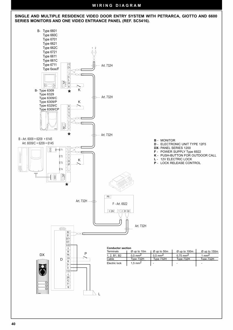
40
W I R I N G D I A G R A M
K
K
K
DP
L
D
6PT3
VIDEO B
C
+-T4
A
12T1
6S5T2 4
BC
A
F - Art. 6922
Art. 732H
B - Art. 6009 + 6209 + 6145 Art. 6009/C + 6209 + 6145
Art. 732H
Art. 732H
Art. 732H
B - Art. 6309 Art. 6329 Art. 6309/C Art. 6309/P Art. 6309/CP
13
1
32
12
4
V3M
+12CH
M
2
E-FP
E+
1
21
PRI
B221 B128V0
EXT+EXT-
MPA
XVLED
B1B2
S+S-
F2F1
SR-L
+12V
M
M
CA
BC
A
Art. 732H
B - Art. 6601 Art. 6611 Art. 660C Art. 661C Art. 6701 Art. 6711
SINGLE AND MULTIPLE RESIDENCE VIDEO DOOR ENTRY SYSTEM WITH PETRARCA, GIOTTO AND 6600
SERIES MONITORS AND ONE VIDEO ENTRANCE PANEL (REF. SC5416).
*
*
*
B - MONITOR
D - ELECTRONIC UNIT TYPE 12F5
DX- PANEL SERIES 1200
F - POWER SUPPLY Type 6922
K - PUSH-BUTTON FOR OUTDOOR CALL
L - 12V ELECTRIC LOCK
P - LOCK RELEASE CONTROL
Conductor section
Terminals Ø up to 10m Ø up to 50m Ø up to 100m Ø up to 150m
1, 2, B1, B2 0,5 mm2 0,5 mm2 0,75 mm2 1 mm2
Cable Type 732H Type 732H Type 732H Type 732H
Electric lock 1,5 mm2 - - -
DX
STASI / Y
STO
FINE
B- Type 6309
Type 6329
Type 6309/C
Type 6309/P
Type 6329/C
Type 6309/CP
B- Type 6601
Type 660C
Type 6701
Type 6621
Type 662C
Type 6721
Type 6611
Type 661C
Type 6711
Type 6xxx/F
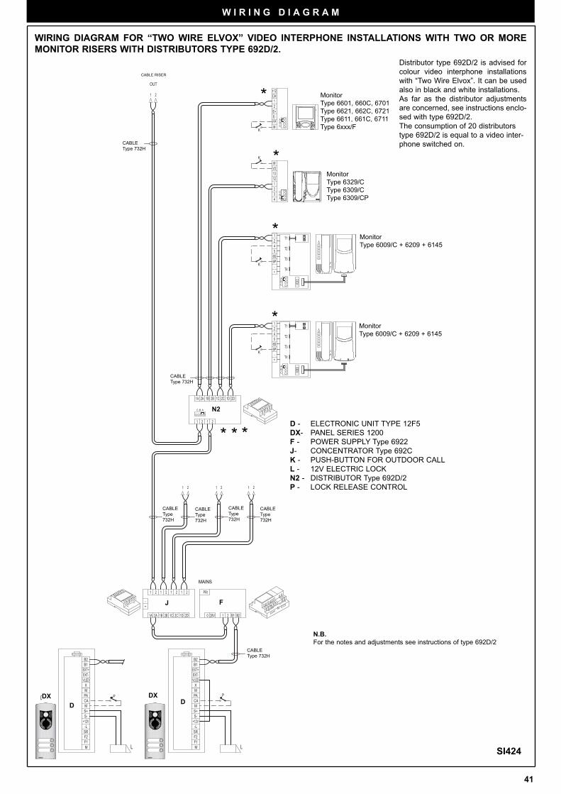
41
W I R I N G D I A G R A M
CA
M
M
+12V-LSR
F1F2
S-S+
B2B1
VLEDX
PAM
EXT-EXT+
1 21 221
+-
11 2
1A 2A 1B 0 28V B11 2 B2
PRI2 21 1 2
2B 1C 2D1D2C
EXT+EXT-
MPA
XVLED
B1B2
S+S-
F2F1
SR-L
+12V
M
M
CA
VIDEOB
A
C
1C 2C2B1A 1B2A
2 11 2
C
13
1
32
12
4
V3M
C
ABFP
E-
M
1
E+2
CH+12
21
2D1D
B A
C
AB
VIDEO
D0
L
P
DP
L
K
K
K
K
D0D
T3
T4
T2
T1
6S
-+
6P
45
21
BC
A
OUT
12
54
6P
+-
6S
T1
T2
T4
T3
R
X
C0R
87
54
9
6
1 2 3
R
CABLE RISER
*
*
*
Monitor
Type 6009/C + 6209 + 6145
Monitor
Type 6009/C + 6209 + 6145
SI424
* *
N2
J
CABLE
Type 732H
CABLE
Type 732H
F
MAINS
WIRING DIAGRAM FOR “TWO WIRE ELVOX” VIDEO INTERPHONE INSTALLATIONS WITH TWO OR MORE
MONITOR RISERS WITH DISTRIBUTORS TYPE 692D/2.
N.B.
For the notes and adjustments see instructions of type 692D/2
CABLE
Type
732H
*
CABLE
Type 732H
Distributor type 692D/2 is advised for
colour video interphone installations
with “Two Wire Elvox”. It can be used
also in black and white installations.
As far as the distributor adjustments
are concerned, see instructions enclo-
sed with type 692D/2.
The consumption of 20 distributors
type 692D/2 is equal to a video inter-
phone switched on.
D - ELECTRONIC UNIT TYPE 12F5
DX- PANEL SERIES 1200
F - POWER SUPPLY Type 6922
J- CONCENTRATOR Type 692C
K - PUSH-BUTTON FOR OUTDOOR CALL
L - 12V ELECTRIC LOCK
N2 - DISTRIBUTOR Type 692D/2
P - LOCK RELEASE CONTROL
*
STASI /
STO
FINEND
STARSI / Y
STO
FINEEND
DX
D
DXD
Monitor
Type 6329/C
Type 6309/C
Type 6309/CP
Monitor
Type 6601, 660C, 6701
Type 6621, 662C, 6721
Type 6611, 661C, 6711
Type 6xxx/F
CABLE
Type
732H
CABLE
Type
732H
CABLE
Type
732H
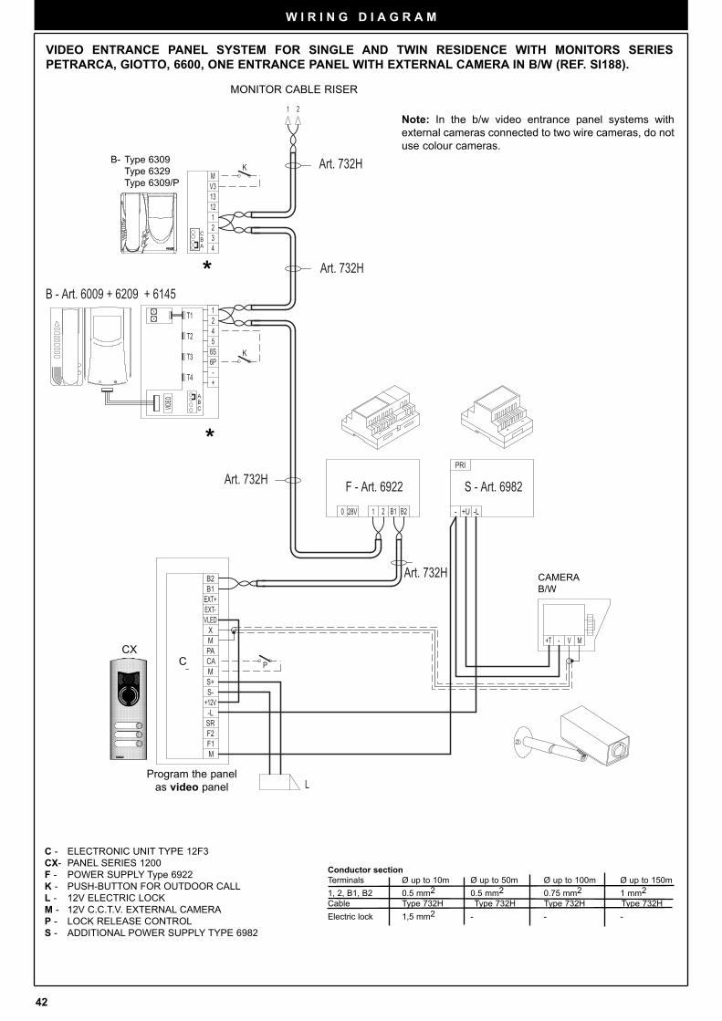
42
W I R I N G D I A G R A M
C - ELECTRONIC UNIT TYPE 12F3
CX- PANEL SERIES 1200
F - POWER SUPPLY Type 6922
K - PUSH-BUTTON FOR OUTDOOR CALL
L - 12V ELECTRIC LOCK
M - 12V C.C.T.V. EXTERNAL CAMERA
P - LOCK RELEASE CONTROL
S - ADDITIONAL POWER SUPPLY TYPE 6982
Conductor section
Terminals Ø up to 10m Ø up to 50m Ø up to 100m Ø up to 150m
1, 2, B1, B2 0.5 mm2 0.5 mm2 0.75 mm2 1 mm2
Cable Type 732H Type 732H Type 732H Type 732H
Electric lock 1,5 mm2 - - -
4T2 56S
T1 21
A
T4 -+
CB
VIDEO
T3 6P
0 28V B11 2 B2
1 2
MV3
4
12
23
1
13
-L- +U
PRI
CA
M
M
+12V-LSR
F1F2
S-S+
B2B1
VLEDX
PAM
EXT-EXT+
MV-+T
K
K
PD
L
A
CB
F - Art. 6922
B - Art. 6009 + 6209 + 6145
Art. 732H
B - Art. 6309
S - Art. 6982
Art. 732H
Art. 732H
Art. 732H
VIDEO ENTRANCE PANEL SYSTEM FOR SINGLE AND TWIN RESIDENCE WITH MONITORS SERIES
PETRARCA, GIOTTO, 6600, ONE ENTRANCE PANEL WITH EXTERNAL CAMERA IN B/W (REF. SI188).
*
*
CAMERA
B/W
MONITOR CABLE RISER
Note: In the b/w video entrance panel systems with
external cameras connected to two wire cameras, do not
use colour cameras.
CXC
B- Type 6309
Type 6329
Type 6309/P
Program the panel
as video panel
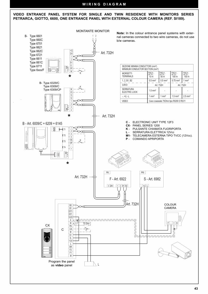
43
W I R I N G D I A G R A M
A
CB
6PT3
VIDEO B
C
+-T4
A
12T1
6S5T2 4
75 Ohm +T - V M
EXT+EXT-
MPA
XVLED
B1B2
S+S-
F2F1
SR-L
+12V
M
M
CA
PRI
+U- -L
13
1
32
12
4
V3M
+12CH
M
2
E-FP
E+
1
21
PRI
B221 B128V0
L
D P
K
K
K
BC
A
F - Art. 6922
B - Art. 6009/C + 6209 + 6145
Art. 732H
B - Art. 6309/C
S - Art. 6982
Art. 732H
Art. 732H
Art. 732H
B - Art. 6601 Art. 660C Art. 6701 Art. 6611 Art. 661C Art. 6711
VIDEO ENTRANCE PANEL SYSTEM FOR SINGLE AND TWIN RESIDENCE WITH MONITORS SERIES
PETRARCA, GIOTTO, 6600, ONE ENTRANCE PANEL WITH EXTERNAL COLOUR CAMERA (REF. SI189).
C - ELECTRONIC UNIT TYPE 12F3
CX- PANEL SERIES 1200
K - PULSANTE CHIAMATA FUORIPORTA
L - SERRATURA ELETTRICA 12Vcc
M1- TELECAMERA ESTERNA TIPO TVCC (12Vcc).
P - COMANDO APRIPORTA
*
*
---
0.5 mm²
Art. 732H
FINO A...UP TO...10 m
Art. 732HCAVO
FINO A...UP TO...150 m100 m
FINO A...UP TO...
1 mm²0.75 mm²
1.5 mm²
50 mUP TO...FINO A...
TERMINALSMORSETTI
1, 2, B1, B2
ELECTRIC LOCKSERRATURA
MINIMUM CONDUCTOR SECTION (mm²)SEZIONE MINIMA CONDUTTORI (mm²)
0.5 mm²
1 mm² 2.5 mm²1.5 mm²-, +U, -L 1 mm²
VIDEO Cavo coassiale 75Ohm tipo RG59 O RG11
COLOUR
CAMERA
MONTANTE MONITORNote: In the colour entrance panel systems with exter-
nal cameras connected to two wire cameras, do not use
b/w cameras.
*
CX
C
Program the panel
as video panel
B- Type 6329/C
Type 6309/C
Type 6309/CP
B- Type 6601
Type 660C
Type 6701
Type 6621
Type 662C
Type 6721
Type 6611
Type 661C
Type 6711
Type 6xxx/F
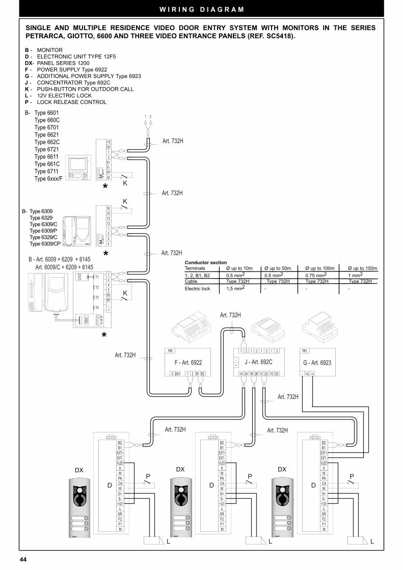
44
W I R I N G D I A G R A M
K
K
K
PD
LL
DP
DP
L
DDD
F - Art. 6922
Art. 732H
B - Art. 6009 + 6209 + 6145 Art. 6009/C + 6209 + 6145
Art. 732H
B - Art. 6309 Art. 6309/C
Art. 732H
Art. 732H
Art. 732H
J - Art. 692C G - Art. 6923
B - Art. 6601 Art. 6611 Art. 660C Art. 661C Art. 6701 Art. 6711
4T2 56S
T1 21
A
T4 -+
CB
VIDEO
T3 6P
0 28V B11 2 B2
PRI
1 2
1
E+
FPE-
2
M
CH+12
MV3
4
12
23
1
13
CA
M
M
+12V-LSR
F1F2
S-S+
B2B1
VLEDX
PAM
EXT-EXT+EXT+
EXT-
MPA
XVLED
B1B2
S+S-
F2F1
SR-L
+12V
M
M
CA
2C 1D 2D1C2B1B2A1A
21
CA
M
M
+12V-LSR
F1F2
S-S+
B2B1
VLEDX
PAM
EXT-EXT+
1 221 1 2
-+
+U-
PRI
A
CB
+I
A
CB
Art. 732H
Art. 732H
Art. 732H
SINGLE AND MULTIPLE RESIDENCE VIDEO DOOR ENTRY SYSTEM WITH MONITORS IN THE SERIES
PETRARCA, GIOTTO, 6600 AND THREE VIDEO ENTRANCE PANELS (REF. SC5418).
*
*
*
B - MONITOR
D - ELECTRONIC UNIT TYPE 12F5
DX- PANEL SERIES 1200
F - POWER SUPPLY Type 6922
G - ADDITIONAL POWER SUPPLY Type 6923
J - CONCENTRATOR Type 692C
K - PUSH-BUTTON FOR OUTDOOR CALL
L - 12V ELECTRIC LOCK
P - LOCK RELEASE CONTROL
Conductor section
Terminals Ø up to 10m Ø up to 50m Ø up to 100m Ø up to 150m
1, 2, B1, B2 0.5 mm2 0.5 mm2 0.75 mm2 1 mm2
Cable Type 732H Type 732H Type 732H Type 732H
Electric lock 1,5 mm2 - - -
DX
STASI / Y
STO
FINE
DX
STASI / Y
STO
FINE
DX
STASI /
STO
FIN
B- Type 6309
Type 6329
Type 6309/C
Type 6309/P
Type 6329/C
Type 6309/CP
B- Type 6601
Type 660C
Type 6701
Type 6621
Type 662C
Type 6721
Type 6611
Type 661C
Type 6711
Type 6xxx/F
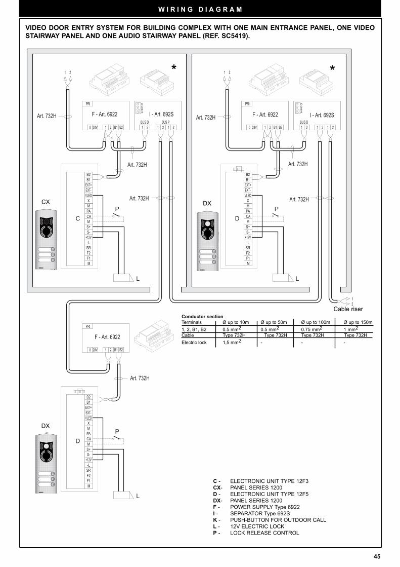
45
W I R I N G D I A G R A M
VIDEO DOOR ENTRY SYSTEM FOR BUILDING COMPLEX WITH ONE MAIN ENTRANCE PANEL, ONE VIDEO
STAIRWAY PANEL AND ONE AUDIO STAIRWAY PANEL (REF. SC5419).
D
CP
L L
PD
P
L
D
C D
F - Art. 6922
Art. 732H
Art. 732HArt. 732H F - Art. 6922 F - Art. 6922I - Art. 692S I - Art. 692S
Art. 732H Art. 732H
Art. 732H
BA
CD D
C
AB
PRI
B221 B128V0
EXT+EXT-
MPA
XVLED
B1B2
S+S-
F2F1
SR-L
+12V
M
M
CA
VLED
-L
M
F2F1
SR
CA
S-+12V
S+M
MPA
X
B2
EXT+EXT-
B1
BUS D1 2
PRI
B221 B128V0BUS P2 11 2
21 1 2
21 120 28V B11 2 B2
PRI
21BUS D
+12V
VLEDEXT-EXT+
CA
M
M
-LSR
F1F2
S-S+
B2B1
X
PAM
21
Art. 732H
**
C - ELECTRONIC UNIT TYPE 12F3
CX- PANEL SERIES 1200
D - ELECTRONIC UNIT TYPE 12F5
DX- PANEL SERIES 1200
F - POWER SUPPLY Type 6922
I - SEPARATOR Type 692S
K - PUSH-BUTTON FOR OUTDOOR CALL
L - 12V ELECTRIC LOCK
P - LOCK RELEASE CONTROL
Conductor section
Terminals Ø up to 10m Ø up to 50m Ø up to 100m Ø up to 150m
1, 2, B1, B2 0.5 mm2 0.5 mm2 0.75 mm2 1 mm2
Cable Type 732H Type 732H Type 732H Type 732H
Electric lock 1,5 mm2 - - -
Cable riser
DX
STASI / Y
STO
FINE
DX
STASI / Y
STO
FINE
CX
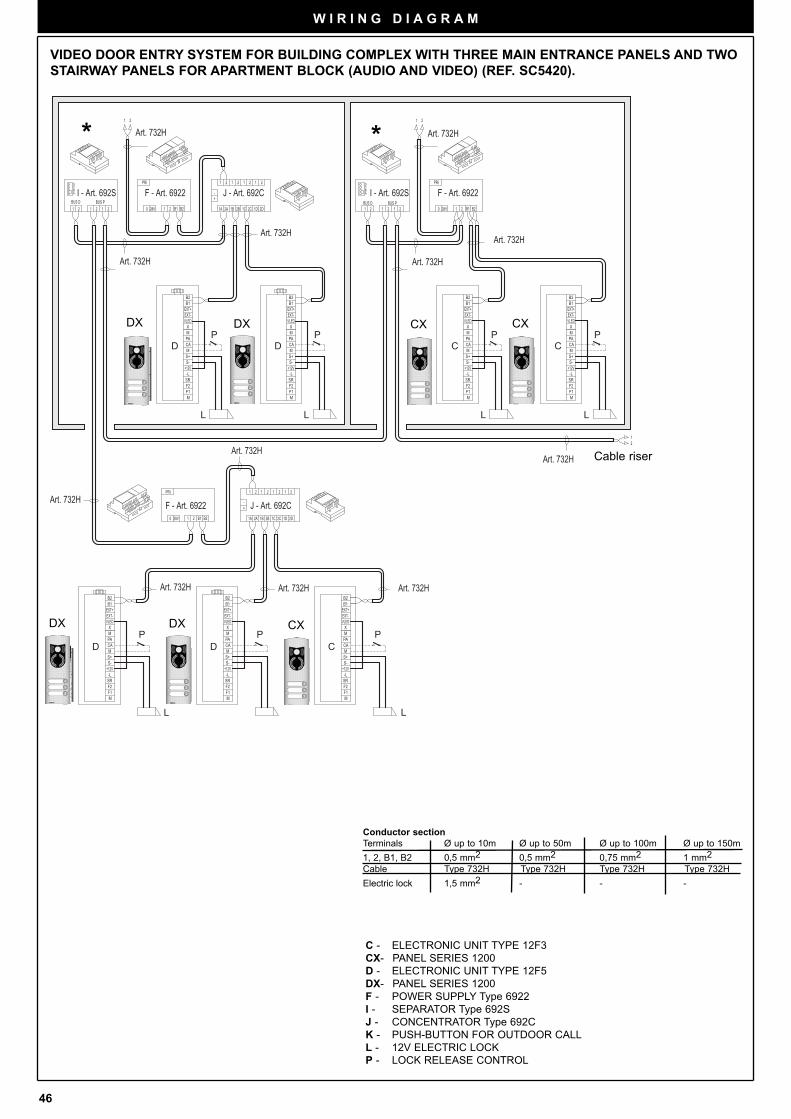
46
W I R I N G D I A G R A M
VIDEO DOOR ENTRY SYSTEM FOR BUILDING COMPLEX WITH THREE MAIN ENTRANCE PANELS AND TWO
STAIRWAY PANELS FOR APARTMENT BLOCK (AUDIO AND VIDEO) (REF. SC5420).
L
PD
PD
L
P P P
L
D D
L
PP
L
C
C C
L
BA
CD D
C
AB
BUS D BUS P BUS D BUS P1 2
PRI
B221 B128V02 11 2
21
EXT+EXT-
MPA
XVLED
B1B2
S+S-
F2F1
SR-L
+12V
M
M
CA CA
M
M
+12V-LSR
F1F2
S-S+
B2B1
VLEDX
PAM
EXT-EXT+
PRI
B221 B128V0
EXT+EXT-
MPA
XVLED
B1B2 B2
B1
VLEDX
PAM
EXT-EXT+
S+S-
F2F1
SR-L
+12V
M
M
CA CA
M
M
+12V-LSR
F1F2
S-S+
1 2
21 12 0 28V B11 2 B2
PRI
21
B1
EXT-EXT+
B2
X
PAM
MS+
+12VS-
CA
SR
F1F2
M
-L
VLED
B1
EXT-EXT+
B2
X
PAM
MS+
+12VS-
CA
SR
F1F2
M
-L
VLED VLED
-L
M
F2F1
SR
CA
S-+12V
S+M
MPA
X
B2
EXT+EXT-
B1
12
+-
211 2 21 1 2
1A 2A 1B 2B 1C 2D1D2C
+-
211 2 21 1 2
1A 2A 1B 2B 1C 2D1D2C
F - Art. 6922 J - Art. 692C
F - Art. 6922I - Art. 692S J - Art. 692C F - Art. 6922I - Art. 692S
Art. 732H
Art. 732H
Art. 732H
Art. 732H
Art. 732H
Art. 732HArt. 732HArt. 732H
Art. 732H
Art. 732HArt. 732H
Art. 732H
D D
D D
C
C C
* *
C - ELECTRONIC UNIT TYPE 12F3
CX- PANEL SERIES 1200
D - ELECTRONIC UNIT TYPE 12F5
DX- PANEL SERIES 1200
F - POWER SUPPLY Type 6922
I - SEPARATOR Type 692S
J - CONCENTRATOR Type 692C
K - PUSH-BUTTON FOR OUTDOOR CALL
L - 12V ELECTRIC LOCK
P - LOCK RELEASE CONTROL
Conductor section
Terminals Ø up to 10m Ø up to 50m Ø up to 100m Ø up to 150m
1, 2, B1, B2 0,5 mm2 0,5 mm2 0,75 mm2 1 mm2
Cable Type 732H Type 732H Type 732H Type 732H
Electric lock 1,5 mm2 - - -
Cable riser
STASI /
ST
STASI / Y
STO
FINE
STARSI / Y
STOP
FINEEND
DXDX CX
STASI /
ST
STASI / Y
STO
FINE
STASI /
STO
FINEND
DXDX CX
STASI /
ST
CX
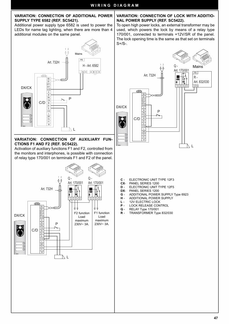
47
W I R I N G D I A G R A M
VARIATION: CONNECTION OF ADDITIONAL POWER
SUPPLY TYPE 6582 (REF. SC5421).
Additional power supply type 6582 is used to power the
LEDs for name tag lighting, when there are more than 4
additional modules on the same panel.
P
L
H - Art. 6582
C/DC/D
Art. 732H
1 2
EXT+EXT-
MPA
XVLED
B1B2
S+S-
F2F1
SR-L
+12V
M
M
CA
PRI
DBA C+U- +I
P
L
Art. 732H
C/DC/D
Q - Art. 170/001
Q - Art. 170/001
1 2
EXT+EXT-
MPA
XVLED
B1B2
S+S-
F2F1
SR-L
+12V
M
M
CA
1 2 3 4 5 54321
VARIATION: CONNECTION OF AUXILIARY FUN-
CTIONS F1 AND F2 (REF. SC5422).
Activation of auxiliary functions F1 and F2, controlled from
the monitors and interphones, is possible with connection
of relay type 170/001 on terminals F1 and F2 of the panel.
F1 function
Load
maximum
230V~ 3A.
F2 function
Load
maximum
230V~ 3A.
L
P
Art. 732H
C/DC/D
Q - Art. 170/001
R - Art. 832/030
54321
PRI
150
CA
M
M
+12V-LSR
F1F2
S-S+
B2B1
VLEDX
PAM
EXT-EXT+
21
VARIATION: CONNECTION OF LOCK WITH ADDITIO-
NAL POWER SUPPLY (REF. SC5422).
To open high power locks, an external transformer may be
used, which powers the lock by means of a relay type
170/001, connected to terminals +12V/SR of the panel.
The lock opening time is the same as that set on terminals
S+/S-.
Mains
C - ELECTRONIC UNIT TYPE 12F3
CX- PANEL SERIES 1200
D - ELECTRONIC UNIT TYPE 12F5
DX- PANEL SERIES 1200
G - ADDITIONAL POWER SUPPLY Type 6923
H - ADDITIONAL POWER SUPPLY
L - 12V ELECTRIC LOCK
P - LOCK RELEASE CONTROL
Q - RELAY Type 170/001
R - TRANSFORMER Type 832/030
Mains
DX/CX
STSI
ST
FI
DX/CX
STSI
ST
FI
DX/CX
STSI
ST
FI
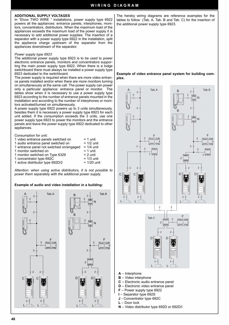
48
W I R I N G D I A G R A M
ADDITIONAL SUPPLY VOLTAGESIn “Elvox TWO WIRE ” installations, power supply type 6922powers all the appliances: entrance panels, interphones, moni-tors, concentrators, distributors. When the maximum load of theappliances exceeds the maximum load of the power supply it isnecessary to add additional power supplies. The insertion of aseparator with a power supply type 6922 in the installation, splitthe appliance charge upstream of the separator from theappliances downstream of the separator.
Power supply type 6923The additional power supply type 6923 is to be used to powerelectronic entrance panels, monitors and concentrators suppor-ting the main power supply type 6922. When there is a lodgeswitchboard there must always be installed a power supply type6923 dedicated to the switchboard.The power supply is required when there are more video entran-ce panels installed and/or when there are more monitors turningon simultaneously at the same call. The power supply can poweronly a particular appliance: entrance panel or monitor. Thetables show when it is necessary to use a power supply type6923 according to the number of entrance panels mounted in theinstallation and according to the number of interphones or moni-tors activated/turned on simultaneously.A power supply type 6922 powers up to 3 units simultaneously,besides them it is necessary a power supply type 6923 for eachunit added. If the consumption exceeds the 3 units, use onepower supply type 6923 to power the monitors and the entrancepanels and leave the power supply type 6922 dedicated to otherappliances.
Consumption for unit:1 video entrance panels switched on = 1 unit1 audio entrance panel switched on = 1/2 unit1 entrance panel not switched on/engaged = 1/4 unit1 monitor switched on = 1 unit1 monitor switched on Type 6329 = 2 unit1 concentrator type 692C = 1/3 unit1 active distributor type 692D/2 = 1/20 unit
Attention: when using active distributors, it is not possible topower them separately with the additional power supply.
Example of audio and video installation in a building:
A – Interphone
B – Video interphone
C – Electronic audio entrance panel
D – Electronic video entrance panel
F – Power supply type 6922
I – Separator type 692S
J - Concentrator type 692C
L – Door lock
N – Video distributor type 692D or 692D/I
Example of video entrance panel system for building com-
plex.
The hereby wiring diagrams are reference examples for the
tables to follow (Tab. A, Tab. B and Tab. C) for the insertion of
the additional power supply type 6923.
Tab. A Tab. B
Tab. C
2
2
22
2
2
A B
B
22
L2
F2
I
2
2
2
2
2
I
2
2
F2
2
2
C
L L
F
2
D
D
2
C
L
2
2
L
D
J
2
2
J
2
2
N
N
L2
D
Tab. A Tab. B
2
2
22
2
2
A B
B
22
2
2
2
2
2
2
F2
2
C
L L
F
D
2
C
L
2
2
L
D
J
2
N
N
STASI /
STO
FIN
STSI
ST
FIEN
STASI /
STO
FINEND
STASI /
STO
FINE
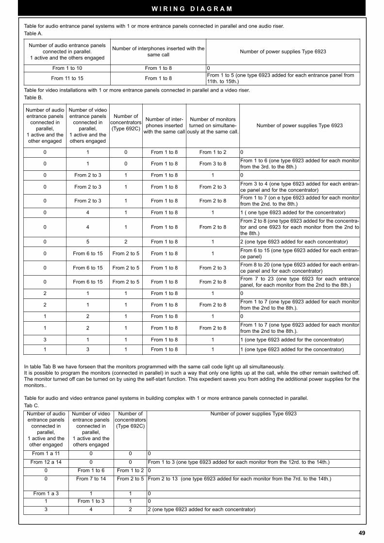
49
W I R I N G D I A G R A M
Number of audio entrance panels
connected in parallel.
1 active and the others engaged
Number of interphones inserted with the
same call Number of power supplies Type 6923
From 1 to 10 From 1 to 8 0
From 11 to 15 From 1 to 8From 1 to 5 (one type 6923 added for each entrance panel from
11th. to 15th.)
Table for audio entrance panel systems with 1 or more entrance panels connected in parallel and one audio riser.
Table A.
Table for video installations with 1 or more entrance panels connected in parallel and a video riser.
Table B.
Number of audio
entrance panels
connected in
parallel,
1 active and the
other engaged
Number of video
entrance panels
connected in
parallel,
1 active and the
others engaged
Number of
concentrators
(Type 692C)
Number of inter-
phones inserted
with the same call
Number of monitors
turned on simultane-
ously at the same call.
Number of power supplies Type 6923
0 1 0 From 1 to 8 From 1 to 2 0
0 1 0 From 1 to 8 From 3 to 8From 1 to 6 (one type 6923 added for each monitor
from the 3rd. to the 8th.)
0 From 2 to 3 1 From 1 to 8 1 0
0 From 2 to 3 1 From 1 to 8 From 2 to 3From 3 to 4 (one type 6923 added for each entran-
ce panel and for the concentrator)
0 From 2 to 3 1 From 1 to 8 From 2 to 8From 1 to 7 (on e type 6923 added for each monitor
from the 2nd. to the 8th.)
0 4 1 From 1 to 8 1 1 ( one type 6923 added for the concentrator)
0 4 1 From 1 to 8 From 2 to 8
From 2 to 8 (one type 6923 added for the concentra-
tor and one 6923 for each monitor from the 2nd to
the 8th.)
0 5 2 From 1 to 8 1 2 (one type 6923 added for each concentrator)
0 From 6 to 15 From 2 to 5 From 1 to 8 1From 6 to 15 (one type 6923 added for each entran-
ce panel)
0 From 6 to 15 From 2 to 5 From 1 to 8 From 2 to 3From 8 to 20 (one type 6923 added for each entran-
ce panel and for each concentrator)
0 From 6 to 15 From 2 to 5 From 1 to 8 From 2 to 8From 7 to 23 (one type 6923 for each entrance
panel, for each monitor from the 2nd to the 8th.)
2 1 1 From 1 to 8 1 0
2 1 1 From 1 to 8 From 2 to 8From 1 to 7 (one type 6923 added for each monitor
from the 2nd to the 8th.).
1 2 1 From 1 to 8 1 0
1 2 1 From 1 to 8 From 2 to 8From 1 to 7 (one type 6923 added for each monitor
from the 2nd to the 8th.).
3 1 1 From 1 to 8 1 1 (one type 6923 added for the concentrator)
1 3 1 From 1 to 8 1 1 (one type 6923 added for the concentrator)
In table Tab B we have forseen that the monitors programmed with the same call code light up all simultaneously.
It is possible to program the monitors (connected in parallel) in such a way that only one lights up at the call, while the other remain switched off.
The monitor turned off can be turned on by using the self-start function. This expedient saves you from adding the additional power supplies for the
monitors..
Table for audio and video entrance panel systems in building complex with 1 or more entrance panels connected in parallel.
Tab C.
Number of audio
entrance panels
connected in
parallel,
1 active and the
other engaged
Number of video
entrance panels
connected in
parallel,
1 active and the
others engaged
Number of
concentrators
(Type 692C)
Number of power supplies Type 6923
From 1 a 11 0 0 0
From 12 a 14 0 0 From 1 to 3 (one type 6923 added for each monitor from the 12rd. to the 14th.)
0 From 1 to 6 From 1 to 2 0
0 From 7 to 14 From 2 to 5 From 2 to 13 (one type 6923 added for each monitor from the 7rd. to the 14th.)
From 1 a 3 1 1 0
1 From 1 to 3 1 0
3 4 2 2 (one type 6923 added for each concentrator)
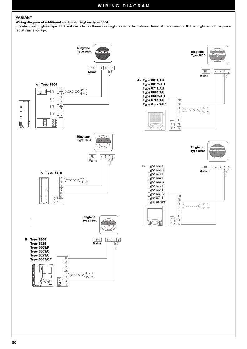
50
W I R I N G D I A G R A M
VARIANTWiring diagram of additional electronic ringtone type 860A.
The electronic ringtone type 860A features a two or three-note ringtone connected between terminal 7 and terminal 8. The ringtone must be powe-
red at mains voltage.
85 74PRI
4
A
T2
T4
T3
56S
-+
6P
CB
VIDEO
T1 21
21
Ringtone
Type 860A
Mains
A- Type 6209
85 74PRI
21
6P
12
6S54
BC
A
Ringtone
Type 860A
Mains
A- Type 8879
K
85 74PRI
21
21
13V3
1
32
12
4
M
BC
A
Ringtone
Type 860A
Mains
85 74PRI
211
E+
FPE-
2
M
CH+12
BA
C
Ringtone
Type 860A
Mains
85 74PRI
211
E+
FPE-
2
M
CH+12
BA
C
Ringtone
Type 860A
Mains
B- Type 6309
Type 6329
Type 6309/P
Type 6309/C
Type 6329/C
Type 6309/CP
A- Type 6611/AU
Type 661C/AU
Type 6711/AU
Type 6601/AU
Type 660C/AU
Type 6701/AU
Type 6xxx/AUF
B- Type 6601
Type 660C
Type 6701
Type 6621
Type 662C
Type 6721
Type 6611
Type 661C
Type 6711
Type 6xxx/F
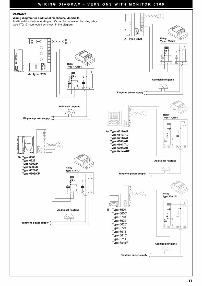
51
W I R I N G D I A G R A M - V E R S I O N S W I T H M O N I T O R 6 3 0 9
VARIANTWiring diagram for additional mechanical doorbells.
Additional doorbells operating at 12V can be connected by using relay
type 170/101 connected as shown in the diagram.
1C
+-
RC 3 42 515
122T1
VIDEO B
C
6P
+-
6S5
T3
T4
T2
A
4
1
Ringtone power supply
Relay
Type 170/101
Additional ringtone
A- Type 6209
15 52 43RC-+
C 1
12
45
6S
21
6PA
CB
Relay
Type 170/101A- Type 8879
12
13V3
1
32
12
4
M
15 52 43RC-+
C 1
BC
A
Relay
Type 170/101
12
+12CH
M
2
E-FP
E+
1
15 52 43RC
-+
C 1
C
AB
Relay
Type 170/101
12
+12CH
M
2
E-FP
E+
1
15 52 43RC
-+
C 1
C
AB
Additional ringtone
Ringtone power supply
Relay
Type 170/101
Additional ringtone
Ringtone power supply
Additional ringtone
Ringtone power supply
Additional ringtone
Ringtone power supply
B- Type 6309
Type 6329
Type 6309/P
Type 6309/C
Type 6329/C
Type 6309/CP
B- Type 6601
Type 660C
Type 6701
Type 6621
Type 662C
Type 6721
Type 6611
Type 661C
Type 6711
Type 6xxx/F
A- Type 6611/AU
Type 661C/AU
Type 6711/AU
Type 6601/AU
Type 660C/AU
Type 6701/AU
Type 6xxx/AUF
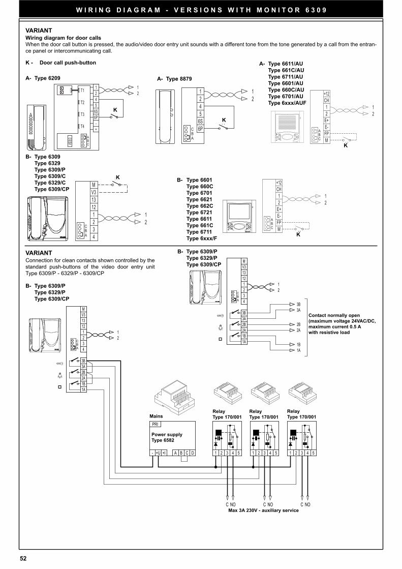
52
W I R I N G D I A G R A M - V E R S I O N S W I T H M O N I T O R 6 3 0 9
VARIANTWiring diagram for door calls
When the door call button is pressed, the audio/video door entry unit sounds with a different tone from the tone generated by a call from the entran-
ce panel or intercommunicating call.
K
1
T2 5
T3 6S
T1 24
T4
A
CB
-+
VIDEO
6P
12
K - Door call push-button
A- Type 6209
K
K
12
45
6S
21
6PA
CB
K
A- Type 8879
K
21
M
4
12
23
1
V313
A
CB
K
K
21
+12CH
M
2
E-FP
E+
1
C
AB
K
K
21
+12CH
M
2
E-FP
E+
1
C
AB
K
VARIANTConnection for clean contacts shown controlled by the
standard push-buttons of the video door entry unit
Type 6309/P - 6329/P - 6309/CP
Contact normally open
(maximum voltage 24VAC/DC,
maximum current 0.5 A
with resistive load
2 1
M
4
12
2 3
1
V3 13
2B 3A
2A
3B
1B 1A
2A 2B
3A 3B
1B 1A
A
C B
1 2
1A 1B
3B
2A
3A 2B
13 V3
1
3 2
12
4
M
NO C NO C C NO
1 2 3 4 5 1 2 3 4 5 5 4 3 2 1 B A C D +U
PRI
- +I
B C
A
Relay
Type 170/001
Power supply
Type 6582
Max 3A 230V - auxiliary service
MainsRelay
Type 170/001
Relay
Type 170/001
B- Type 6309/P
Type 6329/P
Type 6309/CP
B- Type 6601
Type 660C
Type 6701
Type 6621
Type 662C
Type 6721
Type 6611
Type 661C
Type 6711
Type 6xxx/F
A- Type 6611/AU
Type 661C/AU
Type 6711/AU
Type 6601/AU
Type 660C/AU
Type 6701/AU
Type 6xxx/AUF
B- Type 6309
Type 6329
Type 6309/P
Type 6309/C
Type 6329/C
Type 6309/CP
B- Type 6309/P
Type 6329/P
Type 6309/CP
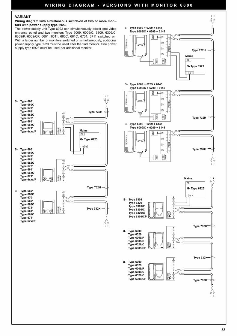
53
W I R I N G D I A G R A M - V E R S I O N S W I T H M O N I T O R 6 6 0 0
VARIANTWiring diagram with simultaneous switch-on of two or more moni-
tors with power supply type 6923.
The power supply unit Type 6922 can simultaneously power one video
entrance panel and two monitors Type 6009, 6009/C, 6309, 6309/C,
6309/P, 6309/CP, 6601, 6611, 660C, 661C, 6701, 6711 switched on.
With a larger number of monitors switched on simultaneously, additional
power supply type 6923 must be used after the 2nd monitor. One power
supply type 6923 must be used per additional monitor.
6PT3
VIDEO B
C
+-T4
A
12T1
6S5T2 4
4T2 56S
T1 21
A
T4 -+
CB
VIDEO
T3 6P
CVIDEO
6PT3
+-T4
A
12T1
6S5T2 4
B
+U-
PRI
21
1 2
+I
G- Type 6923
Type 732H
Type 732H
Type 732H
Mains
B- Type 6309
Type 6329
Type 6309/P
Type 6309/C
Type 6329/C
Type 6309/CP
G- Type 6923
B- Type 6009 + 6209 + 6145
Type 6009/C + 6209 + 6145
B- Type 6009 + 6209 + 6145
Type 6009/C + 6209 + 6145
B- Type 6009 + 6209 + 6145
Type 6009/C + 6209 + 6145
21
1 2
PRI
- +U
M
4
12
23
1
V313
13V3
1
32
12
4
M
13V3
1
32
12
4
M
+I
A
CB
BC
A
BC
A
Type 732H
Type 732H
Type 732H
Mains
21
1 2
PRI
- +U
+12CH
M
2
E-FP
E+
1
1
E+
FPE-
2
M
CH+12
+12CH
M
2
E-FP
E+
1
+I
C
AB
BA
C
C
AB
G- Type 6923
Mains
Type 732H
Type 732H
Type 732H
B- Type 6309
Type 6329
Type 6309/P
Type 6309/C
Type 6329/C
Type 6309/CP
B- Type 6309
Type 6329
Type 6309/P
Type 6309/C
Type 6329/C
Type 6309/CP
B- Type 6601
Type 660C
Type 6701
Type 6621
Type 662C
Type 6721
Type 6611
Type 661C
Type 6711
Type 6xxx/F
B- Type 6601
Type 660C
Type 6701
Type 6621
Type 662C
Type 6721
Type 6611
Type 661C
Type 6711
Type 6xxx/F
B- Type 6601
Type 660C
Type 6701
Type 6621
Type 662C
Type 6721
Type 6611
Type 661C
Type 6711
Type 6xxx/F
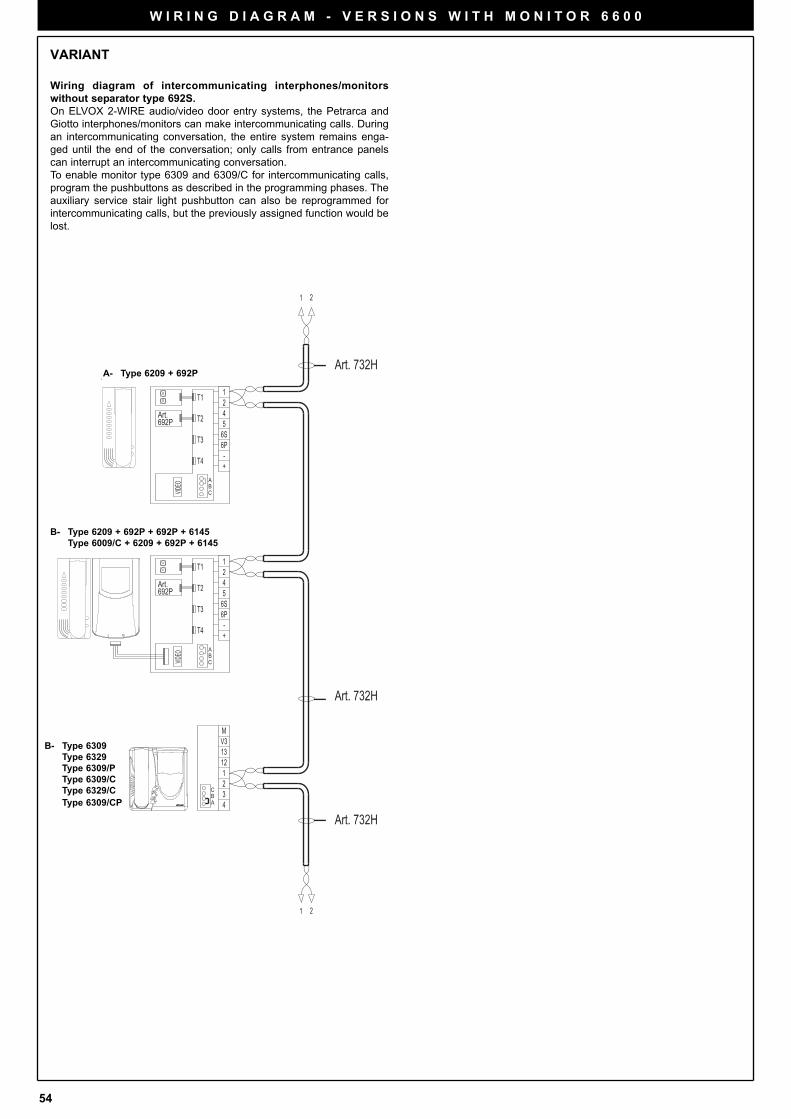
54
6PT3
VIDEO B
C
+-T4
A
12T1
6S5T2 4
6PT3
VIDEO B
C
+-T4
A
12T1
6S5T2 4
21
21
M
4
12
23
1
V313
Art.692P
692PArt.
A
CB
Art. 732H
Art. 732H
Art. 732H
Art. 6209 + 6009 + 692P + 6145Art. 6209 + 6009/C + 692P + 6145
Art. 6209 + 692P
Art. 6309,Art. 6329,Art. 6309/C
VARIANT
Wiring diagram of intercommunicating interphones/monitors
without separator type 692S.
On ELVOX 2-WIRE audio/video door entry systems, the Petrarca and
Giotto interphones/monitors can make intercommunicating calls. During
an intercommunicating conversation, the entire system remains enga-
ged until the end of the conversation; only calls from entrance panels
can interrupt an intercommunicating conversation.
To enable monitor type 6309 and 6309/C for intercommunicating calls,
program the pushbuttons as described in the programming phases. The
auxiliary service stair light pushbutton can also be reprogrammed for
intercommunicating calls, but the previously assigned function would be
lost.
W I R I N G D I A G R A M - V E R S I O N S W I T H M O N I T O R 6 6 0 0
B- Type 6309
Type 6329
Type 6309/P
Type 6309/C
Type 6329/C
Type 6309/CP
A- Type 6209 + 692P
B- Type 6209 + 692P + 692P + 6145
Type 6009/C + 6209 + 692P + 6145
55
SAFETY INSTRUCTIONS FOR INSTALLERS
- Carefully read the instructions on this leaflet: they give important information on the safety, use and maintenance of the installa-
tion.
- After removing the packing, check the integrity of the set. Packing components (plastic bags, expanded polystyrene etc.) are dan-
gerous for children. Installation must be carried out according to national safety regulations.
- It is convenient to fit close to the supply voltage source a proper bipolar type switch with 3 mm separation (minimum) between
contacts.
- Before connecting the set, ensure that the data on the label correspond to those of the mains.
- Use this set only for the purposes designed, i.e.for electric door-opener systems. Any other use may be dangerous. The manu-
facturer is not responsible for damage caused by improper, erroneous or irrational use.
- Before cleaning or maintenance, disconnect the set.
- In case of failure or faulty operation, disconnect the set and do not open it.
- For repairs apply only to the technical assistance centre authorized by the manufacturer.
- Safety may be compromised if these instructions are disregarded.
- Do not obstruct opening of ventilation or heat exit slots and do not expose the set to dripping or sprinkling of water.
- Installers must ensure that manuals with the above instructions are left on connected units after installation, for users' information.
- All items must only be used for the purposes designed.
- The ominipolar switch must be easily accessed.
WARNING: to avoid the possibility of hurting yourself, this unit must be fixed to the wall according to the installation instructions.
- This leaflet must always be enclosed with the equipment.
Directive 2002/96/EC (WEEE)
The crossed-out wheelie bin symbol marked on the product indicates that at the end of its useful life, the product must be handled
separately from household refuse and must therefore be assigned to a differentiated collection centre for electrical and electronic
equipment or returned to the dealer upon purchase of a new, equivalent item of equipment.
The user is responsible for assigning the equipment, at the end of its life, to the appropriate collection facilities.
Suitable differentiated collection, for the purpose of subsequent recycling of decommissioned equipment and environmentally com-
patible treatment and disposal, helps prevent potential negative effects on health and the environment and promotes the recycling
of the materials of which the product is made. For further details regarding the collection systems available, contact your local waste
disposal service or the shop from which the equipment was purchased.
Risks connected to substances considered as dangerous (WEEE).
According to the WEEE Directive, substances since long usually used on electric and electronic appliances are considered dange-
rous for people and the environment. The adequate differentiated collection for the subsequent dispatch of the appliance for the
recycling, treatment and dismantling (compatible with the environment) help to avoid possible negative effects on the environment
and health and promote the recycling of material with which the product is compound.

56
FILIALE DI MILANO:
Via Conti Biglia, 2 20162 (MILANO)
Tel. 02/6473360-6473561
Fax 02/6473733
E-mail: [email protected]
FILIALE TOSCANA:
Via Lunga 4/R 50142 FIRENZE
Tel. 055/7322870 - Telefax. 055/7322670
E-mail: [email protected]
UNI EN ISO 9001
ELVOX COSTRUZIONI ELETTRONICHE S.p.A.
35011 Campodarsego (PD) - ITALYVia Pontarola, 14/A
Tel. 049/9202511 r.a. - Phone international... 39/49/9202511
Telefax Italia 049/9202603Telefax Export Dept... 39/49/9202601
ELVOX INTERNET SERVICEE-mail: [email protected]
http://www.elvox.comE-mail export dept: