Video Decoder EI3 Extender Board Manual - Farnell
55
a Video Decoder EI3 Extender Board Manual an EZ-Extender ® product Revision 1.0, May 2012 Part Number 82-000253-01 Analog Devices, Inc. One Technology Way Norwood, Mass. 02062-9106
Transcript of Video Decoder EI3 Extender Board Manual - Farnell

a
Video Decoder EI3 Extender Board Manual an EZ-Extender® product
Revision 1.0, May 2012
Part Number 82-000253-01
Analog Devices, Inc.One Technology WayNorwood, Mass. 02062-9106

Copyright Information©2012 Analog Devices, Inc., ALL RIGHTS RESERVED. This document may not be reproduced in any form without prior, express written consent from Analog Devices, Inc.
Printed in the USA.
DisclaimerAnalog Devices, Inc. reserves the right to change this product without prior notice. Information furnished by Analog Devices is believed to be accurate and reliable. However, no responsibility is assumed by Analog Devices for its use; nor for any infringement of patents or other rights of third parties which may result from its use. No license is granted by impli-cation or otherwise under the patent rights of Analog Devices, Inc.
Trademark and Service Mark NoticeThe Analog Devices logo, Blackfin, CrossCore, EngineerZone, EZ-Board, EZ-Extender, EZ-KIT Lite, and VisualDSP++ are registered trademarks of Analog Devices, Inc.
All other brand and product names are trademarks or service marks of their respective owners.

Regulatory Compliance The Video Decoder EI3 Extender Board is designed to be used solely in a laboratory environment. The board is not intended for use as a consumer end product or as a portion of a consumer end product. The board is an open system design which does not include a shielded enclosure and there-fore may cause interference to other electrical devices in close proximity. This board should not be used in or near any medical equipment or RF devices.
The Video Decoder EI3 Extender Board is in the process of being certi-fied to comply with the essential requirements of the European EMC directive 89/336/EEC (inclusive 93/68/EEC) and, therefore, carries the “CE” mark.
The extender board contains ESD (electrostatic discharge) sensitive devices. Electrostatic charges readily accumulate on the human body and equipment and can discharge without detection. Permanent damage may occur on devices subjected to high-energy discharges. Proper ESD precautions are recommended to avoid performance degradation or loss of functionality. Store unused extender boards in the protective shipping package.


CONTENTS
PREFACE
Product Overview ........................................................................ ix
Purpose of This Manual ................................................................ x
Intended Audience ....................................................................... xi
Manual Contents ......................................................................... xi
What’s New in This Manual ........................................................ xii
Technical Support ....................................................................... xii
Supported Products .................................................................... xiii
Product Information .................................................................. xiii
Analog Devices Web Site ...................................................... xiii
EngineerZone ....................................................................... xiv
Related Documents ..................................................................... xv
Notation Conventions ................................................................. xv
USING VIDEO DECODER EI3 EXTENDER BOARD
Package Contents .......................................................................... 1-2
Supported Operating Systems ........................................................ 1-2
System Requirements .................................................................... 1-3
Video Decoder EI3 Extender Board Installation ............................. 1-3
Video Decoder EI3 Extender Board Manual v

Contents
High-Performance HDMI Receiver (ADV7842) ............................ 1-5
Expansion Interface III ................................................................. 1-6
Example Programs ........................................................................ 1-7
Board Design Database ................................................................. 1-7
VIDEO DECODER EI3 EXTENDER BOARD HARDWARE REFERENCE
System Architecture ...................................................................... 2-2
Software-Controlled Switches (SoftConfig) ................................... 2-3
Overview of SoftConfig ........................................................... 2-3
Programming SoftConfig ........................................................ 2-7
ADV7842_INT_GPIOx Signal ............................................... 2-9
SPORT_ENABLE Signal ........................................................ 2-9
Connectors ................................................................................. 2-10
Component Connector (J1) .................................................. 2-11
S-Video Connector (J2) ........................................................ 2-11
VGA Connector (J3) ............................................................. 2-11
Expansion Interface III (EI3) Connectors (J4) ....................... 2-12
HDMI Connector (J5–6) ...................................................... 2-12
Composite Connector (J7) .................................................... 2-13
Power Connector (P1) ........................................................... 2-13
LEDs ......................................................................................... 2-14
HDMI Detect LED (LED1–2) .............................................. 2-14
Power LED (LED3) .............................................................. 2-14
VIDEO DECODER EI3 EXTENDER BOARD BILL OF
vi Video Decoder EI3 Extender Board Manual

Contents
MATERIALS
VIDEO DECODER EI3 EXTENDER BOARD SCHEMATIC
Title Page ..................................................................................... B-1
EI3 Connector/GPIO Extender .................................................... B-2
Buffers/SoftConfig ........................................................................ B-3
Video Mode ................................................................................. B-4
ADV7842 .................................................................................... B-5
ADV7842 Memory ....................................................................... B-6
Video Connectors ......................................................................... B-7
Video Connectors 2 ...................................................................... B-8
Power ........................................................................................... B-9
INDEX
vii Video Decoder EI3 Extender Board Manual

Contents
viii Video Decoder EI3 Extender Board Manual

PREFACE
Thank you for purchasing the Video Decoder EI3 Extender Board, an
EZ-Extender® for EZ-KIT Lite®/EZ-Board® evaluation systems with the expansion interface 3 (EI3).The EZ-KIT Lite/EZ-Board and Video Decoder EI3 Extender Board are designed to be used in conjunction with the CrossCore® Embedded Studio (CCES) development environment.
To learn more about Analog Devices development software, go to http://www.analog.com/processors/tools.
Product OverviewThe Video Decoder EI3 Extender Board is a separately sold daughter board that plugs onto the EI3 of an EZ-KIT Lite/EZ-Board evaluation system. The extender board aids the design and prototyping phases of embedded processor-targeted applications.
The board extends the capabilities of the evaluation system by providing a connection between the parallel peripheral interface (PPI) of the processor and the ADV7842 video decoder. The serial port interface (SPORT) is used to receive audio data. The two-wire interface (TWI) port of the pro-cessor is used to communicate with the video decoders and SoftConfig on the extender.
Video Decoder EI3 Extender Board Manual ix

Purpose of This Manual
The following is a list of the Video Decoder EI3 Extender Board interfaces.
• Video interface
• ADV7842 — Dual HDMI 1.4 fast switching receiver with 12-bit, 170 MHz video and graphics digitizer and 3-D comb filter decoder
• Video connectors
• Two HDMI
• One SVIDEO
• One component
• One composite
• One VGA
• Software-controlled switches for board configuration
• Expansion Interface III
• No power supply required: derives power from the EZ-KIT Lite/EZ-Board
• CE certified
Purpose of This ManualThe Video Decoder EI3 Extender Board Manual provides instructions for installing the product hardware (board). The text describes operation and configuration of the board components and provides guidelines for run-ning your own code on the Video Decoder EI3 Extender Board. Finally, a schematic and a bill of materials are provided for reference.
x Video Decoder EI3 Extender Board Manual

Preface
Intended AudienceThe primary audience for this manual is a programmer who is familiar with Analog Devices processors. This manual assumes that the audience has a working knowledge of the appropriate processor architecture, instruction set, and C/C++ programming languages.
Programmers who are unfamiliar with Analog Devices processors can use this manual, but should supplement it with other texts that describe your target architecture and hardware development tools.
Programmers who are unfamiliar with the CrossCore Embedded Studio programming environment or the mating evaluation board, should refer to the CCES online help or the manual describing the board (see “Related Documents”).
Manual ContentsThe manual consists of:
• Chapter 1, “Using Video Decoder EI3 Extender Board” on page 1-1Provides basic product information.
• Chapter 2, “Video Decoder EI3 Extender Board Hardware Refer-ence” on page 2-1Provides information about the product’s hardware components.
• Appendix A, “Video Decoder EI3 Extender Board Bill Of Materi-als” on page A-1Provides a list of hardware components used to manufacture the board.
Video Decoder EI3 Extender Board Manual xi

What’s New in This Manual
• Appendix B, “Video Decoder EI3 Extender Board Schematic” on page B-1Provides all circuits on the extender board.
What’s New in This ManualThis is the first revision of the Video Decoder EI3 Extender Board Manual.
Technical SupportYou can reach Analog Devices processors and DSP technical support in the following ways:
• Post your questions in the processors and DSP support community at EngineerZone®:http://ez.analog.com/community/dsp
• Submit your questions to technical support directly at:http://www.analog.com/support
• E-mail your questions about processors, DSPs, and tools develop-ment software from CrossCore Embedded Studio or VisualDSP++®:
Choose Help > Email Support. This creates an e-mail [email protected] and automatically attaches your CrossCore Embedded Studio or VisualDSP++ version infor-mation and license.dat file.
• E-mail your questions about processors and processor applications to: [email protected] [email protected] (Greater China support)
• In the USA only, call 1-800-ANALOGD (1-800-262-5643)
xii Video Decoder EI3 Extender Board Manual

Preface
• Contact your Analog Devices sales office or authorized distributor. Locate one at:www.analog.com/adi-sales
• Send questions by mail to:Processors and DSP Technical SupportAnalog Devices, Inc.Three Technology WayP.O. Box 9106Norwood, MA 02062-9106USA
Supported ProductsThis extender board supports EZ-KIT Lite/EZ-Board evaluation systems with EI3.
Product InformationProduct information can be obtained from the Analog Devices Web site and the CCES online help system.
Analog Devices Web SiteThe Analog Devices Web site, www.analog.com, provides information about a broad range of products—analog integrated circuits, amplifiers, converters, and digital signal processors.
To access a complete technical library for each processor family, go to http://www.analog.com/processors/technical_library. The manuals selection opens a list of current manuals related to the product as well as a link to the previous revisions of the manuals. When locating your manual
Video Decoder EI3 Extender Board Manual xiii

Product Information
title, note a possible errata check mark next to the title that leads to the current correction report against the manual.
Also note, myAnalog.com is a free feature of the Analog Devices Web site that allows customization of a Web page to display only the latest infor-mation about products you are interested in. You can choose to receive weekly e-mail notifications containing updates to the Web pages that meet your interests, including documentation errata against all manuals. myAnalog.com provides access to books, application notes, data sheets, code examples, and more.
Visit myAnalog.com (found on the Analog Devices home page) to sign up. If you are a registered user, just log on. Your user name is your e-mail address.
EngineerZoneEngineerZone is a technical support forum from Analog Devices. It allows you direct access to ADI technical support engineers. You can search FAQs and technical information to get quick answers to your embedded processing and DSP design questions.
Use EngineerZone to connect with other DSP developers who face similar design challenges. You can also use this open forum to share knowledge and collaborate with the ADI support team and your peers. Visit http://ez.analog.com to sign up.
xiv Video Decoder EI3 Extender Board Manual

Preface
Related DocumentsFor additional information about the processor, refer to the following publications.
Table 1. Related Processor Publications
Title Description
Processor Data Sheet General functional description, pinout, and timing of the processor
Processor Hardware Reference Description of the internal processor archi-tecture and all register functions
Blackfin® Processor Programming Reference Description of all allowed processor assembly instructions
Notation ConventionsText conventions used in this manual are identified and described as follows.
Example Description
Close command (File menu)
Titles in reference sections indicate the location of an item within the CCES environment’s menu system (for example, the Close command appears on the File menu).
{this | that} Alternative required items in syntax descriptions appear within curly brackets and separated by vertical bars; read the example as this or that. One or the other is required.
[this | that] Optional items in syntax descriptions appear within brackets and sepa-rated by vertical bars; read the example as an optional this or that.
[this,…] Optional item lists in syntax descriptions appear within brackets delim-ited by commas and terminated with an ellipse; read the example as an optional comma-separated list of this.
Video Decoder EI3 Extender Board Manual xv
Notation Conventions
.SECTION Commands, directives, keywords, and feature names are in text with letter gothic font.
filename Non-keyword placeholders appear in text with italic style format.
Note: For correct operation, ...A Note provides supplementary information on a related topic. In the online version of this book, the word Note appears instead of this
symbol.
Caution: Incorrect device operation may result if ...Caution: Device damage may result if ... A Caution identifies conditions or inappropriate usage of the product that could lead to undesirable results or product damage. In the online version of this book, the word Caution appears instead of this symbol.
Warning: Injury to device users may result if ... A Warning identifies conditions or inappropriate usage of the product that could lead to conditions that are potentially hazardous for the devices users. In the online version of this book, the word Warning appears instead of this symbol.
Example Description
xvi Video Decoder EI3 Extender Board Manual

1 USING VIDEO DECODER EI3 EXTENDER BOARD
This chapter provides the setup procedure for the Video Decoder EI3
Extender Board and describes two types of interfaces the extender supports.The information is presented in the following order.
• “Package Contents” on page 1-2
• “Supported Operating Systems” on page 1-2
• “System Requirements” on page 1-3
• “Video Decoder EI3 Extender Board Installation” on page 1-3
• “High-Performance HDMI Receiver (ADV7842)” on page 1-5
• “Expansion Interface III” on page 1-6
• “Example Programs” on page 1-7
• “Board Design Database” on page 1-7
For information about the CCES integrated development environment (IDE), refer to the online help.
Video Decoder EI3 Extender Board Manual 1-1

Package Contents
Package ContentsYour Video Decoder EI3 Extender Board package contains the following items.
• Video Decoder EI3 Extender Board
• A bag containing hardware for securing the extender board onto the EZ-KIT Lite/EZ-Board
• Two video cables: one HDMI and one component
• Release notes containing information about the product download
Contact the vendor where you purchased your extender board or contact Analog Devices, Inc. if any item is missing.
Supported Operating SystemsCrossCore Embedded Studio is supported on the following operating systems:
• Windows® XP Professional SP3 (32-bit only)
• Windows Vista™ Business, Enterprise, or Ultimate SP2 (32-bit only)
• Windows 7 Professional, Enterprise, or Ultimate (32- and 64-bit)
Windows Vista and Windows 7 users may experience User Access Control (UAC) related errors if the software is installed into a pro-tected location, such as Program Files or Program Files (x86). We recommend installing the software in a non-UAC-protected location.
1-2 Video Decoder EI3 Extender Board Manual

Using Video Decoder EI3 Extender Board
System RequirementsVerify that your PC has these minimum requirements for the CCES installation:
• 2 GHz single-core processor
• 1 GB RAM
• 8 GB available disk space
• One open USB port
A faster disk drive decreases the build time, especially for a large amount of source files.
Video Decoder EI3 Extender Board Installation
Follow these instructions to ensure correct operation of the product hard-ware and software.
1. Attach the extender board to the EZ-KIT Lite/EZ-Board.The J1 connector on the extender board can be connected to the P1A, P2A, or P3A connector on the EZ-KIT Lite/EZ-Board. Refer to the example program for a reference to the proper connector.
Video Decoder EI3 Extender Board Manual 1-3
Video Decoder EI3 Extender Board Installation
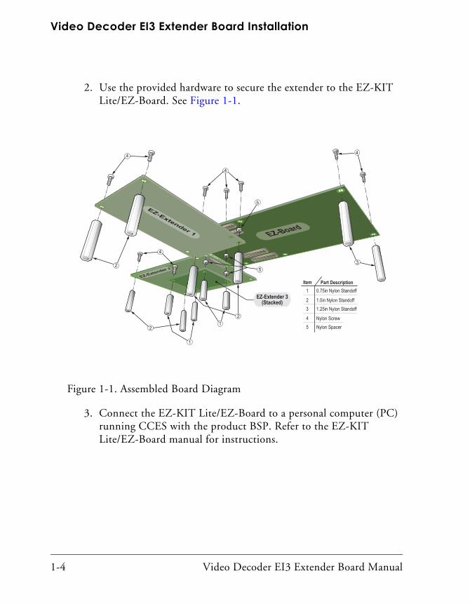
2. Use the provided hardware to secure the extender to the EZ-KIT Lite/EZ-Board. See Figure 1-1.
Figure 1-1. Assembled Board Diagram
Part DescriptionItem0.75in Nylon Standoff1
1.0in Nylon Standoff2 1.25in Nylon Standoff3
3
Nylon Screw4 Nylon Spacer5
EZ-Extender 3(Stacked)
2
2
1
1
2
4
5
4 4
4
5
3. Connect the EZ-KIT Lite/EZ-Board to a personal computer (PC) running CCES with the product BSP. Refer to the EZ-KIT Lite/EZ-Board manual for instructions.
1-4 Video Decoder EI3 Extender Board Manual

Using Video Decoder EI3 Extender Board
High-Performance HDMI Receiver (ADV7842)
The video interface consists of the ADV7842 dual HDMI fast switching receiver with video and graphics digitizer and 3-D comb filter. This device interfaces to the processor’s parallel peripheral interface (PPI). It operates in 24-, 16- or 8-bit modes. YCbCr and RGB video modes are supported.
The ADV7842 receiver is a high quality, single-chip, 2:1 multiplexed HDMI receiver and graphics digitizer with an integrated multi-format video decoder.
The ADV7842 receiver uses external 256 Mb DDR SDRAM for 3-D comb and frame synchronizer.
The ADV7842 receiver incorporates a dual input HDMI 1.4-compatible receiver that supports all HDTV formats up to 1080p and display resolu-tions up to UXGA. It also incorporates Xpressview fast switching on both input HDMI ports. Using the Analog Devices hardware-based HDCP engine that minimizes software overhead, Xpressview technology allows fast switching between any HDMI input ports in less than one second.
HDCP 1.4 support with internal HDCP keys. There is a version of the product, where the ADV7842 device is programmed with internal HDCP keys (ADZS-DECODEK-EX3). Consumers must have HDCP adopter status (consult Digital Content Protection, LLC for licensing require-ments) to purchase any components with internal HDCP keys. In order to interface with consumer electronics, a board with internal HDCP keys is required.
The ADV7842 receiver supports all mandatory HDMI 1.4 3-D TV for-mats in addition to all HDTV formats up to 1080p.
The ADV7842 receiver also integrates an HDMI v1.4 CEC controller that supports the capability discovery and control (CDC) feature.
Video Decoder EI3 Extender Board Manual 1-5

Expansion Interface III
The ADV7842 receiver offers a flexible audio output port for the audio data decoded from the HDMI stream.
ADV7842 receiver can be configured to generate an interrupt based on various events. The TWI port is used for communication between the receiver and processor. The parallel peripheral interface (PPI) is used to receive video data. The serial port (SPORT) is used to receive audio data. An interrupt signal from the receiver is connected to a GPIO signal on the processor. The GPIO signal is configured via a software switch. Refer to “Video Decoder EI3 Extender Board Schematic” on page B-1 for more information.
For more information about the ADV7842, go to www.analog.com and search for ADV7842.
An example program demonstrating capabilities of the ADV7842 device is available by installing the Video Decoder EI3 Extender Board Support Package (BSP).
Expansion Interface IIIThe Expansion Interface III (EI3) allows an extender board to be used across various hardware platforms that have the same expansion interface connectors.
The EI3 implemented on the Video Decoder EI3 Extender Board contains the PPI, SPORT, TWI and GPIO ports. These signals are used for the peripherals on the extender. The connectors contain a majority of the pro-cessor’s signals. For pinout information, go to “Video Decoder EI3 Extender Board Schematic” on page B-1. The mechanical dimensions of the expansion connectors can be obtained by contacting “Technical Support”.
The Video Decoder EI3 Extender Board can interface with EZ-KIT Lites/EZ-Boards operating at an IO voltage of 3.3V. Other IO voltages
1-6 Video Decoder EI3 Extender Board Manual

Using Video Decoder EI3 Extender Board
are not supported. The extender can be powered from either the EZ-KIT Lite/EZ-Board or through the on-board 5V power connector (P1).
For more information about extender boards, visit the Analog Devices Web site (www.analog.com).
Limits to current and interface speed must be taken into consideration when using the EI3. Current for the EI3 can be sourced from the EZ-KIT Lite/EZ-Board; therefore, the current should be limited to 200 mA for 5V and 300 mA for the 3.3V planes. If more current is required, then a sepa-rate power connector and a regulator must be designed on the daughter card. Additional circuitry can add extra loading to signals, decreasing their maximum effective speed.
Analog Devices does not support and is not responsible for the effects of additional circuitry.
Example ProgramsExample programs are included with the Video Decoder EI3 Extender Board BSP. Example programs demonstrate various capabilities of the product. The support package is installed on top of CrossCore Embedded Studio. Once installed, the example programs can be found in the <install_path>\Video_Decoder_EI3_Extender_Board-RelX.X.X\Video_D
ecoder_EI3 directory where X.X.X denotes the support package release number.
Board Design DatabaseA .zip file containing all of the electronic information required for the design, layout, fabrication and assembly of the product is available for download from the Analog Devices board design database at:http://www.analog.com/en/processors-dsp/blackfin/proces-
sors/board-design-database/resources/index.html.
Video Decoder EI3 Extender Board Manual 1-7

Board Design Database
1-8 Video Decoder EI3 Extender Board Manual

2 VIDEO DECODER EI3 EXTENDER BOARD HARDWARE REFERENCE
This chapter describes the hardware design of the Video Decoder EI3
Extender Board.The following topics are covered.
• “System Architecture” on page 2-2Describes the daughter board configuration and explains how the board components interface with the processor.
• “Software-Controlled Switches (SoftConfig)” on page 2-3List and describe signals routed through the software-controlled switches.
• “Connectors” on page 2-10Shows the locations and provides part numbers for the on-board connectors. In addition, the manufacturer and part number infor-mation is provided for the mating parts.
• “LEDs” on page 2-14Describes the on-board LEDs.
Video Decoder EI3 Extender Board Manual 2-1

System Architecture
System ArchitectureA block diagram of the Video Decoder EI3 Extender Board is shown in Figure 2-1.
Figure 2-1. Video Decoder EI3 Extender Board Block Diagram
ADV7842Video Decoder
HDMI HDMI VGA Component CompositeSVIDEO
DDRSDRAM
EI3 ConnectorGPIOTWIEPPI
Power
VoltageRegulation
Bus Transceiver
3.3V
PPI
1.8V
SoftConfig
74CB3Q16211
SoftConfig
74AVC8T245
SoftConfig
PI3C3125
SoftConfig
MCP23017
2.5V
SPORT
TWI SPORTINT
2-2 Video Decoder EI3 Extender Board Manual
Video Decoder EI3 Extender Board Hardware Reference
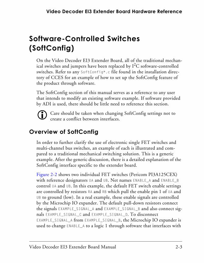
Software-Controlled Switches (SoftConfig)
On the Video Decoder EI3 Extender Board, all of the traditional mechan-ical switches and jumpers have been replaced by I2C software-controlled switches. Refer to any SoftConfig*.c file found in the installation direc-tory of CCES for an example of how to set up the SoftConfig feature of the product through software.
The SoftConfig section of this manual serves as a reference to any user that intends to modify an existing software example. If software provided by ADI is used, there should be little need to reference this section.
Care should be taken when changing SoftConfig settings not to create a conflict between interfaces.
Overview of SoftConfigIn order to further clarify the use of electronic single FET switches and multi-channel bus switches, an example of each is illustrated and com-pared to a traditional mechanical switching solution. This is a generic example. After the generic discussion, there is a detailed explanation of the SoftConfig interface specific to the extender board.
Figure 2-2 shows two individual FET switches (Pericom PI3A125CEX) with reference designators UA and UB. Net names ENABLE_A and ENABLE_B control UA and UB. In this example, the default FET switch enable settings are controlled by resistors RA and RB which pull the enable pin 1 of UA and UB to ground (low). In a real example, these enable signals are controlled by the Microchip IO expander. The default pull-down resistors connect the signals EXAMPLE_SIGNAL_A and EXAMPLE_SIGNAL_B and also connect sig-nals EXAMPLE_SIGNAL_C and EXAMPLE_SIGNAL_D. To disconnect EXAMPLE_SIGNAL_A from EXAMPLE_SIGNAL_B, the Microchip IO expander is used to change ENABLE_A to a logic 1 through software that interfaces with
Video Decoder EI3 Extender Board Manual 2-3

Software-Controlled Switches (SoftConfig)
the Microchip. The same procedure for ENABLE_B disconnects EXAMPLE_SIGNAL_C from EXAMPLE_SIGNAL_D.
Figure 2-2. Example of Individual FET Switches
Figure 2-3 shows the equivalent circuit to Figure 2-2 but utilizes mechan-ical switches that are in the same package. The default is shown by black boxes located closer to the ON label of the switches. In order to disconnect these switches, physically move the switch to the OFF position.
Figure 2-3. Example of Mechanical Switch Equivalent to Figure 2-2
2-4 Video Decoder EI3 Extender Board Manual

Video Decoder EI3 Extender Board Hardware Reference
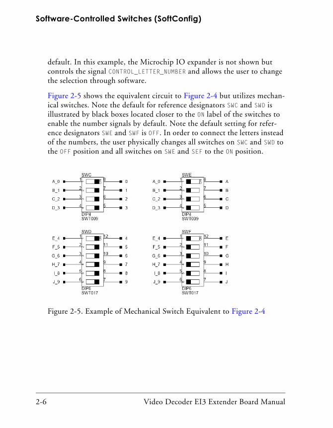
Figure 2-4 shows a bus switch example, reference designator UC (Pericom PI3LVD512ZHE), selecting between lettered functionality and numbered functionality. The signals on the left side are multiplexed signals with naming convention letter_number.
Figure 2-4. Example of a Bus Switch
The right side of the circuit shows the signals separated into letter and number, with the number on the lower group (eg. 0B1) and the letter on the upper group (eg. 0B2). The default setting is controlled by the signal CONTROL_LETTER_NUMBER which is pulled low. This selects the number sig-nals on the right to be connected to the multiplexed signals on the left by
Video Decoder EI3 Extender Board Manual 2-5
Software-Controlled Switches (SoftConfig)
default. In this example, the Microchip IO expander is not shown but controls the signal CONTROL_LETTER_NUMBER and allows the user to change the selection through software.
Figure 2-5 shows the equivalent circuit to Figure 2-4 but utilizes mechan-ical switches. Note the default for reference designators SWC and SWD is illustrated by black boxes located closer to the ON label of the switches to enable the number signals by default. Note the default setting for refer-ence designators SWE and SWF is OFF. In order to connect the letters instead of the numbers, the user physically changes all switches on SWC and SWD to the OFF position and all switches on SWE and SEF to the ON position.
Figure 2-5. Example of Mechanical Switch Equivalent to Figure 2-4
2-6 Video Decoder EI3 Extender Board Manual

Video Decoder EI3 Extender Board Hardware Reference
Programming SoftConfigOn the Video Decoder EI3 Extender Board, a single Microchip MCP23017 device controls individual and electronic bus switches via TWI. The device has the following programming characteristics:
• There are two programmable GPIO registers.
GPIO Register Register Address
GPIOA 0x12
GPIOB 0x13
• Each GPIO register controls eight signals (software switches).
• By default, the GPIO signals function as input signals; therefore, all electronic switches are in the OFF state.The signals must be programmed as output signals to override their default values. The following table shows the Microchip register addresses and values that must be written to them to program the signals as output signals.
IODIR Register IODIR Register Address Value to be Written to Program Signals as Outputs
IODIRA 0x00 0
IODIRB 0x01 0
Each example in CrossCore Embedded Studio includes source files that program the soft switches, even if the default settings are being used. The README for each example identifies only the signals that are being changed
Video Decoder EI3 Extender Board Manual 2-7

Software-Controlled Switches (SoftConfig)
from their default values. The code that programs the soft switches is located in two files:
• SoftConfig_Decoder.c for configuring the extender board
• SoftConfig_xxx.c for configuring the EZ-KIT Lite/EZ-Board; xxx identifies the EZ-KIT Lite/EZ-Board file in each example.
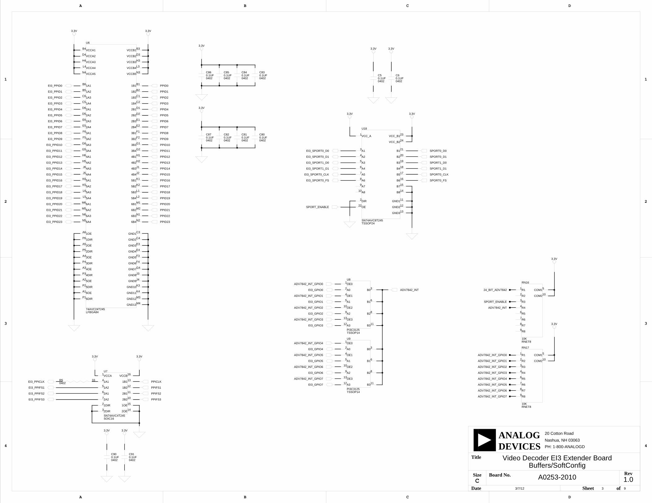
Page 2 of “Video Decoder EI3 Extender Board Schematic” on page B-1 shows how the GPIO expanders are connected to the board’s ICs.
U12 is a 24-bit bus switch. The switch connects the decoder to the processor.
U8–9 are 2-port bus switches. The switches select the GPIO signals to be used as the interrupt for the ADV7842 device (U10).
U18 is an 8-port bus switch. The switch is used to connects/disconnect the SPORT interface of the processor to the ADV7842 receiver.
Table 2-1 and Table 2-2 show the output signals of the GPIO expander (U2) with a TWI address of 0100 110X, where X represents the read or write bit. The signals that control an individual FET have an entry under the FET column. The Component Connected column shows the board IC that is connected if the FET is enabled.
Table 2-1. Output Signals of GPIO Expander (U2 Port A)
Bit Signal Name Description FET Component Connected
Default
0 24_BIT_ADV7842 24-bit video mode U12 U10 OFF
1 Not Used
2 SPORT_ENABLE Enable SPORT interface U18 U10 OFF
3 Not Used
4 Not Used
5 Not Used
2-8 Video Decoder EI3 Extender Board Manual

Video Decoder EI3 Extender Board Hardware Reference
ADV7842_INT_GPIOx SignalThe ADV7842_INT_GPIOx signal connects the interrupt signal of the ADV7842 video decoder to one of eight GPIO pins of the processor. U2 ports GPB0–7 select the connection to the appropriate GPIO signal via the U8–9 bus switches.
SPORT_ENABLE SignalThe SPORT_ENABLE signal connects the audio signal of the ADV7842 video decoder to the SPORT interface of the processor. U2 port GPA2 enables or disables the connection via the U18 bus switch. By default, the audio is disabled.
6 Not Used
7 Not Used
Table 2-2. Output Signals of GPIO Expander (U2 Port B)
Bit Signal Name Description FET Component Connected
Default
0 ADV7842_INT_GPIO0 Decoder interrupt U8 U10 OFF
1 ADV7842_INT_GPIO1 Decoder interrupt U8 U10 OFF
2 ADV7842_INT_GPIO2 Decoder interrupt U8 U10 OFF
3 ADV7842_INT_GPIO3 Decoder interrupt U8 U10 OFF
4 ADV7842_INT_GPIO4 Decoder interrupt U9 U10 OFF
5 ADV7842_INT_GPIO5 Decoder interrupt U9 U10 OFF
6 ADV7842_INT_GPIO6 Decoder interrupt U9 U10 OFF
7 ADV7842_INT_GPIO7 Decoder interrupt U9 U10 OFF
Table 2-1. Output Signals of GPIO Expander (U2 Port A) (Cont’d)
Bit Signal Name Description FET Component Connected
Default
Video Decoder EI3 Extender Board Manual 2-9
Connectors
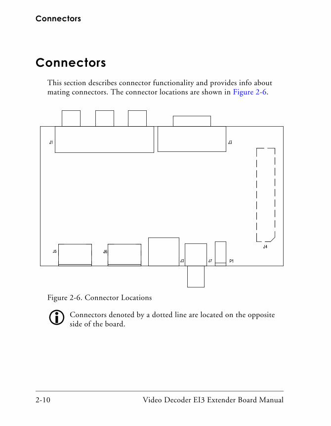
ConnectorsThis section describes connector functionality and provides info about mating connectors. The connector locations are shown in Figure 2-6.
Figure 2-6. Connector Locations
Connectors denoted by a dotted line are located on the opposite side of the board.
2-10 Video Decoder EI3 Extender Board Manual

Video Decoder EI3 Extender Board Hardware Reference
Component Connector (J1)The component connector (J1) is a group of three RCA jacks which con-nect to the ADV7842 video decoder. The connector can be used for YPrPb and RGB modes and supports SD, ED, and HD video modes.
Part Description Manufacturer Part Number
Component (3x1 RCA) CUI RCJ-32265
Mating Cable
Component cable BELKIN AV21000-06
S-Video Connector (J2)The S-Video connector (J2) is a DIN connector to the ADV7842 video decoder. The connector can be used for Y-C mode and supports SD, ED, and HD video modes.
Part Description Manufacturer Part Number
S-Video CUI MD-40SM
Mating Cable
S-Video cable BELKIN F8V308-06
VGA Connector (J3)The VGA connector (J3) is a DSUB15 connector which connects to the ADV7842 video decoder. The connector can be used for RGB mode and supports SD, ED, and HD video modes.
Part Description Manufacturer Part Number
VGA EDAC 634-015-263-032
Video Decoder EI3 Extender Board Manual 2-11

Connectors
Expansion Interface III (EI3) Connectors (J4)One board-to-board connector (J4) provides signals from the PPI, SPORT, TWI, and GPIO interfaces of the processor. The connector is located on the top side of the board.
Part Description Manufacturer Part Number
120-pin, 0.6 mm HIROSE FX8-120S-SV(21)
Mating Connector
120-pin, 0.6 mm HIROSE FX8-120P-SV1(91)
HDMI Connector (J5–6)The HDMI connectors (J5–6) are HDMI receptacles connected to the ADV7842 video decoder. The connector can be used for YCbCr and RGB modes and supports SD, ED, and HD video modes. It supports ARC and is v.1.4 compliant.
Part Description Manufacturer Part Number
HDMI FCI 10029449-002TLF
Mating Cable
HDMI cable MEDIABRIDGE 91-02X-06B
Mating Cable
VGA cable BELKIN F2N028-06
Part Description Manufacturer Part Number
2-12 Video Decoder EI3 Extender Board Manual

Video Decoder EI3 Extender Board Hardware Reference
Composite Connector (J7)The composite connector (J7) is a single RCA jack connected to the ADV7842 video decoder. The connector can be used for CVBS and sup-ports SD, ED, and HD video modes.
Part Description Manufacturer Part Number
Composite (1 RCA) SWITCHCRAFT PJRAN1X1U01X
Mating Cable
Composite Cable KOBICONN 17FH101
Power Connector (P1)Under normal circumstances, the power connector is not needed because the Video Decoder EI3 Extender Board derives its power from the EZ-KIT Lite/EZ-Board. If the EZ-KIT Lite/EZ-Board is not able to sup-ply enough power to the Video Decoder EI3 Extender Board, then an external power supply can be connected to P1 and power the extender and EZ-KIT Lite/EZ-Board.
Part Description Manufacturer Part Number
0.65 mm power jack CUI 045-0883R
Mating Cable
[email protected] power supply GLOBETEK GS-1750(R)
Video Decoder EI3 Extender Board Manual 2-13

LEDs
LEDsThis section describes the on-board LEDs.
HDMI Detect LED (LED1–2)When LED1 or LED2 is lit solid (yellow), it indicates that a valid connection is sensed on the HDMI connector.
Power LED (LED3)When LED3 is lit solid (green), it indicates that power is being supplied to the board properly.
2-14 Video Decoder EI3 Extender Board Manual
A VIDEO DECODER EI3 EXTENDER BOARD BILL OF MATERIALS
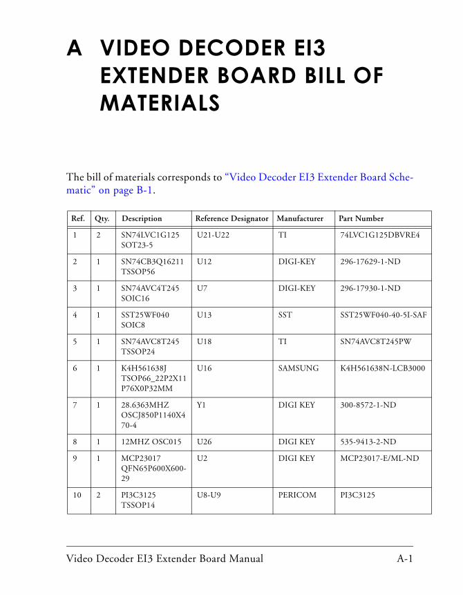
The bill of materials corresponds to “Video Decoder EI3 Extender Board Sche-
F
matic” on page B-1.
Ref. Qty. Description Reference Designator Manufacturer Part Number
1 2 SN74LVC1G125 SOT23-5
U21-U22 TI 74LVC1G125DBVRE4
2 1 SN74CB3Q16211 TSSOP56
U12 DIGI-KEY 296-17629-1-ND
3 1 SN74AVC4T245 SOIC16
U7 DIGI-KEY 296-17930-1-ND
4 1 SST25WF040 SOIC8
U13 SST SST25WF040-40-5I-SA
5 1 SN74AVC8T245 TSSOP24
U18 TI SN74AVC8T245PW
6 1 K4H561638J TSOP66_22P2X11P76X0P32MM
U16 SAMSUNG K4H561638N-LCB3000
7 1 28.6363MHZ OSCJ850P1140X470-4
Y1 DIGI KEY 300-8572-1-ND
8 1 12MHZ OSC015 U26 DIGI KEY 535-9413-2-ND
9 1 MCP23017 QFN65P600X600-29
U2 DIGI KEY MCP23017-E/ML-ND
10 2 PI3C3125 TSSOP14
U8-U9 PERICOM PI3C3125
Video Decoder EI3 Extender Board Manual A-1

11 1 74AVC24T245 LFBGA84
U6 DIGI KEY 296-17662-1-ND
12 1 ADP1706-3.3V LFCSP8
VR1 ANALOG DEVICES
ADP1706ACPZ-3.3-R7
13 3 ADP1715 MSOP8 VR2-VR4 ANALOG DEVICES
ADP1715ARMZ-1.8-R7
14 1 ADP1715 MSOP8 VR5 ANALOG DEVICES
ADP1715ARMZ-2.5-R7
15 1 ADV7842 BGA256C100P16X16_1700X1700
U10 ANALOG DEVICES
ADV7842KBCZ-5
16 1 RCA 1X1 CON012 J7 SWITCH-CRAFT
PJRAN1X1U01X
17 1 PWR .65MM CON027
P1 DIGI-KEY CP1-022PJCT-ND
18 1 1A RESETABLE 1206
F1 RAYCHEM NANOSMDC110F-2
19 1 DSUB 15P EDAC_634-015-263-032
J3 MOUSER 587-634-015-263-032
20 2 HDMI 19P FCI_10029449-002TLF
J5-J6 FCI 10029449-002LF
21 1 RCA 3X1 CUI-STACK_RCJ-32265
J1 DIGI KEY CP-1446-ND
22 1 MINI-DIN 4PIN CUI-STACK_MD-40SM
J2 DIGI KEY CP-2240-ND
23 1 .6MM 120PIN HIROSE_FX8-120S-SV(21)
J4 HIROSE FX8-120S-SV(21)
Ref. Qty. Description Reference Designator Manufacturer Part Number
A-2 Video Decoder EI3 Extender Board Manual

Video Decoder EI3 Extender Board Bill Of Materials
24 3 10K 1/10W 5% 0805
R11,R15-R16 VISHAY CRCW080510K0JNEA
25 3 10K 1/10W 5% 0805
R9-R10,R17 VISHAY CRCW080510K0JNEA
26 2 10K 31MW 5% RNET8
RN16-RN17 CTS 746X101103JP
27 31 0.1UF 10V 10% 0402
C5-C6,C11,C15-C19,C21-C22,C24-C26,C44,C58,C66,C68,C77,C80-C87,C90-C94
AVX 0402ZD104KAT2A
28 31 0.01UF 16V 10% 0402
C29-C37,C42-C43,C45-C48,C50-C51,C54,C57,C59-C65,C67,C69-C72
AVX 0402YC103KAT2A
29 1 10K 1/16W 5% 0402
R55 VISHAY CRCW040210K0FKED
30 7 4.7K 1/16W 5% 0402
R45-R46,R51-R52,R57,R60-R61
VISHAY CRCW04024K70JNED
31 2 0 1/16W 5% 0402 R1-R2 PANASONIC ERJ-2GE0R00X
32 6 0 1/16W 5% 0402 R4,R6,R8,R26-R28 PANASONIC ERJ-2GE0R00X
33 3 33 1/16W 5% 0402
R3,R5,R56 VISHAY CRCW040233R0JNEA
34 9 24.0 1/10W 1% 0603
R30,R32,R34-R35,R38-R41,R43
DIGI-KEY 311-24.0HRTR-ND
35 2 4.7UF 6.3V 20% 0603
C55-C56 AVX 06036D475MAT2A
36 1 1UF 6.3V 20% 0402
C78 PANASONIC ECJ-0EB0J105M
37 4 100 1/16W 5% 0402
R12-R14,R54 DIGI-KEY 311-100JRTR-ND
38 2 27PF 50V 5% 0402
C96-C97 AVX 04025A270JAT2A
Ref. Qty. Description Reference Designator Manufacturer Part Number
Video Decoder EI3 Extender Board Manual A-3
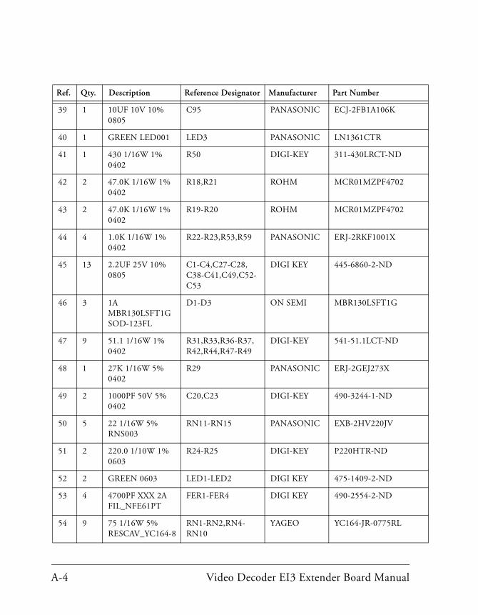
39 1 10UF 10V 10% 0805
C95 PANASONIC ECJ-2FB1A106K
40 1 GREEN LED001 LED3 PANASONIC LN1361CTR
41 1 430 1/16W 1% 0402
R50 DIGI-KEY 311-430LRCT-ND
42 2 47.0K 1/16W 1% 0402
R18,R21 ROHM MCR01MZPF4702
43 2 47.0K 1/16W 1% 0402
R19-R20 ROHM MCR01MZPF4702
44 4 1.0K 1/16W 1% 0402
R22-R23,R53,R59 PANASONIC ERJ-2RKF1001X
45 13 2.2UF 25V 10% 0805
C1-C4,C27-C28,C38-C41,C49,C52-C53
DIGI KEY 445-6860-2-ND
46 3 1A MBR130LSFT1G SOD-123FL
D1-D3 ON SEMI MBR130LSFT1G
47 9 51.1 1/16W 1% 0402
R31,R33,R36-R37,R42,R44,R47-R49
DIGI-KEY 541-51.1LCT-ND
48 1 27K 1/16W 5% 0402
R29 PANASONIC ERJ-2GEJ273X
49 2 1000PF 50V 5% 0402
C20,C23 DIGI-KEY 490-3244-1-ND
50 5 22 1/16W 5% RNS003
RN11-RN15 PANASONIC EXB-2HV220JV
51 2 220.0 1/10W 1% 0603
R24-R25 DIGI-KEY P220HTR-ND
52 2 GREEN 0603 LED1-LED2 DIGI KEY 475-1409-2-ND
53 4 4700PF XXX 2A FIL_NFE61PT
FER1-FER4 DIGI KEY 490-2554-2-ND
54 9 75 1/16W 5% RESCAV_YC164-8
RN1-RN2,RN4-RN10
YAGEO YC164-JR-0775RL
Ref. Qty. Description Reference Designator Manufacturer Part Number
A-4 Video Decoder EI3 Extender Board Manual

Video Decoder EI3 Extender Board Bill Of Materials
55 4 5A RCLAMP0524 DIO_RCLAMP0524
D7-D10 SEMTECH RCLAMP0524P.TCT
56 2 6A RCLAMP0504 DIO_RCLAMP0504
D4-D5 SEMTECH RCLAMP0504P.TCT
57 1 30MA DB3X314 DIO_DB3X314
D6 PANASONIC DB3X314K0L
58 1 499 1/10W 1% 0402
R58 PANASONIC ERJ-2RKF4990X
59 1 75.0 1/10W 1% 0402
R7 PANASONIC ERJ-2RKF75R0X
Ref. Qty. Description Reference Designator Manufacturer Part Number
Video Decoder EI3 Extender Board Manual A-5

A-6 Video Decoder EI3 Extender Board Manual

1.01 9
A0253-2010
Video Decoder EI3 Extender BoardTitle Page
3/7/12
D
4
3
2
1
A B C
20 Cotton Road
Nashua, NH 03063
A B C D
4
3
2
1
PH: 1-800-ANALOGD
C
Title
Size Board No.
Date Sheet of
DEVICESANALOG
Rev
SchematicVideo Decoder EI3 Extender Board

EI3 Connector/GPIO Extender
3/7/12
1.02 9
A0253-2010
Video Decoder EI3 Extender Board
D
4
3
2
1
A B C
20 Cotton Road
Nashua, NH 03063
A B C D
4
3
2
1
PH: 1-800-ANALOGD
C
Title
Size Board No.
Date Sheet of
DEVICESANALOG
Rev
R4 00402
C11
04020.1UF
3.3V
TP8
U2
MCP23017QFN65P600X600-29N
17
18
19
20
5
8
9
14
16
15
11
12
28
24
23
27
22
26
21
25
1
2
3
413A2 GPB7
GPB6
GPB5
GPB4
GPB0
GPA4
GPB1
GPA5
GPB2
GPA6
GPA7
GPB3
A1
A0
INTB
INTA
RESET
SDA
SCL
VDD
GPA3
GPA2
GPA1
GPA0
PWR_IN
J4
.6MMHIROSE_FX8-120S-SV(21)
101
100
71
70
120
118
116
114
112
110
108
106
104
102
98
96
94
92
90
88
86
84
82
80
78
76
74
72
119
117
115
113
111
109
107
105
103
99
97
95
93
91
89
87
85
83
81
79
77
75
73
69
66
6867
64
61
63
65
11
62
36
35
8
6
4
2
9
7
5
3
1
12
10
59
60
55
53
51
49
47
45
43
41
39
56
54
52
50
40
48
46
44
42
58
57
3433
16
18
20
22
14
24
26
28
30
32
13
15
17
19
21
23
25
27
29
31
37 38SPI0_SEL_CSPI0_SEL_B
SPORT1_D1
SPORT0_TDV
PPI0_FS1
RSVD5
GND6
RSVD2
PPI0_D3
GND5
PPI0_D9
PPI0_D13
SPORT0_D1
SPORT1_TDV
GND7
PPI0_FS3
RSVD4
PPI0_D11
RSVD3
PPI0_D1
PPI0_D5
PPI0_D7
SPI0_D2 SPI0_D3
RESET_OUT*
GND12
SCL1*
GPIO2
GND10
TMR_A
GND9
SPI0_RDY
GND11
RSVD8
TWI0_A0*
SPI0_SEL1/SPI0_SS*
SDA1*
GPIO0
GPIO4
GPIO6
TMR_C
RSVD6
RSVD7
RSVD9
RESET_IN*
UART0_RX
PPI0_D17
PPI0_D14
VIN
GND1
USB_VCC
PPI0_D23
PPI0_D19
RSVD1
GND2
GND3
PPI0_D21
SPORT_INT
GND8
UART0_TX
GND4
WAKE*
GND13
EXT_BOOT
SLEEP*
RSVD11 RSVD12
RSVD10
GND14
TMR_B
GND15
GPIO3
SCL0*
GND16
SPI0_MISO
SPI0_SEL_A
SPORT0_CLK
SPORT0_FS
SPORT1_D0
GND18
PPI0_FS2
RSVD15
PPI0_INT
PPI0_D4
PPI0_D6
PPI0_D10
GND21
PPI0_D16
PPI0_D20
GND22
GND23
RSVD17
TMR_D*
GPIO7*
GPIO5
GPIO1
SDA0*
SPI0_CLK
SPI0_MOSI
GND17
SPORT0_D0
SPORT1_FS
SPORT1_CLK
PPI0_CLK
RSVD14
GND19
PPI0_D2
GND20
PPI0_D8
PPI0_D12
PPI0_D15
PPI0_D18
PPI0_D22
VIO
GND24
PS_IN
RSVD13
CLKOUT
RSVD16
PPI0_D0
3.3V
3.3V
R910K0805
R10
080510K
DNP
R1110K0805
DNP
R15
080510K
R16
DNP080510K
R17
080510K
R2
DNP04020
DNP
R100402
SPORT_ENABLE
ADV7842_INT_GPIO0
ADV7842_INT_GPIO1
ADV7842_INT_GPIO2
ADV7842_INT_GPIO3
ADV7842_INT_GPIO4
ADV7842_INT_GPIO5
ADV7842_INT_GPIO6
ADV7842_INT_GPIO7
24_BIT_ADV7842
EI3_PPIFS3
EI3_SPORT0_D0
EI3_PPID15
EI3_PPID13
EI3_PPID11
EI3_PPID9
EI3_PPID7
EI3_PPID5
EI3_PPID3
EI3_PPID1
EI3_PPID14
EI3_PPID12
EI3_PPID10
EI3_PPID8
EI3_PPID6
EI3_PPID4
EI3_PPID2
EI3_PPID0
EI3_PPIFS2
EI3_PPIFS1
EI3_PPID20
EI3_PPID19
EI3_PPID22
EI3_PPID21
EI3_PPID23
EI3_PPID16 EI3_PPID17
EI3_PPID18
EI3_PPICLK
EI3_SPORT1_D1EI3_SPORT0_D1
EI3_SPORT0_CLKEI3_SPORT0_CLK
EI3_SPORT0_FS
EI3_SPORT0_FS
EI3_SPORT1_D0EI3_SPORT1_FS
EI3_SPORT1_FS
EI3_SPORT1_CLKEI3_SPORT1_CLK
EI3_SDA
EI3_SDA
EI3_SCL
EI3_SCL
EI3_GPIO7EI3_GPIO6
EI3_GPIO5EI3_GPIO4
EI3_GPIO3EI3_GPIO2
EI3_GPIO1EI3_GPIO0
EI3_RESET
EI3_RESETVIN
USB_VCC
TWI Address 0100 110x
SoftConfig control signals
x is the R/W bit. Read - 1, Write - 0
3.3V
3.3V
3.3V
3.3V
3.3V
3.3V
R5 330402
1.03 9
A0253-2010
Video Decoder EI3 Extender BoardBuffers/SoftConfig
3/7/12
D
4
3
2
1
A B C
20 Cotton Road
Nashua, NH 03063
A B C D
4
3
2
1
PH: 1-800-ANALOGD
C
Title
Size Board No.
Date Sheet of
DEVICESANALOG
Rev
3.3V
RN16
RNET810K
10
5
9
8
7
6
4
3
2
1R1
R2
R3
R4
R5
R6
R7
R8
COM1
COM2
3.3V
RN17
10KRNET8
10
5
9
8
7
6
4
3
2
1R1
R2
R3
R4
R5
R6
R7
R8
COM1
COM2
C50.1UF0402
C6
04020.1UF
3.3V
C800.1UF0402
C81
04020.1UF
C820.1UF0402
C90
04020.1UF
C910.1UF0402
3.3V
3.3V
U7
SN74AVC4T245SOIC16
15
10
11
12
13
161
4
6
2
7
3
5
142OE
1A2
2DIR
2A2
1DIR
2A1
1A1
VCCA VCCB
1B1
1B2
2B1
2B2
1OE
3.3V
3.3V
74AVC24T245LFBGA84
U6
M4
M3
K4
K3
J4
J3
G4
F4
F3
A6
P6
A1
P1
A2
P2
A3
P3
A4
P4
N3N4
L3
H3
D3
B3
L4
H4
D4
B4
E4
E3
C4
C3
A5
H5
J6
J5
K6
K5
L6
L5
M6
N6
N5
H6
M5
F1
M1
F2
M2
G1
N1
G2
N2
P5
B6
B5
C6
C5
D6
D5
E6
E5
C2
J2
J1
C1
H2
B2
H1
B1
D1
K1
D2
K2
E1
L1
L2
E2
G5
G6
F5
F63A1
3A2
3A3
3A4
2B4
5B4
5B3
2B3
5B2
2B2
5B1
2B1
1B1
4B1
1B2
4B2
1B3
4B3
4B4
1B4
2A4
2A3
2A2
2A1
1A4
1A3
1A2
1A1
2DIR
6B4
3B4
6B3
3B3
6B2
3B2
6B1
3B1
6A2
4A1
6A4
6A3
6A1
5A4
5A3
5A2
5A1
4A4
4A3
4A2
2OE
GND1
GND2
GND3
GND4
VCCA1
VCCA2
VCCA3
VCCA4
VCCB1
VCCB2
VCCB3
VCCB4
VCCA5 VCCB5
3DIR
3OE
4DIR
4OE
5DIR
5OE
6DIR
6OE
1DIR
1OE
GND5
GND6
GND7
GND8
GND9
GND10
GND11
GND12
GND13
U18
TSSOP24SN74AVC8T245
22
24
231
13
12
112
14
15
16
17
18
19
20
21
10
9
8
7
6
5
4
3A1
A2
A3
A4
A5
A6
A7
A8
B1
B2
B3
B4
B5
B6
B7
B8
DIR GND1
GND2
GND3
VCC_A VCC_B1
VCC_B2
OE
U8
PI3C3125TSSOP14
12 11
13
9 8
10
5 6
4
2 3
1OE0
B0A0
OE1
B1A1
OE2
B2A2
OE3
B3A3
U9
PI3C3125TSSOP14
12 11
13
9 8
10
5 6
4
2 3
1OE0
B0A0
OE1
B1A1
OE2
B2A2
OE3
B3A3
C83
04020.1UF
C840.1UF0402
C85
04020.1UF
C86
04020.1UF
C870.1UF0402
3.3V
SPORT_ENABLE
SPORT_ENABLE
ADV7842_INT_GPIO0
ADV7842_INT_GPIO0
ADV7842_INT_GPIO1
ADV7842_INT_GPIO1
ADV7842_INT_GPIO2
ADV7842_INT_GPIO2
ADV7842_INT_GPIO3
ADV7842_INT_GPIO3
ADV7842_INT_GPIO4
ADV7842_INT_GPIO4
ADV7842_INT_GPIO5
ADV7842_INT_GPIO5
ADV7842_INT_GPIO6
ADV7842_INT_GPIO6
ADV7842_INT_GPIO7
ADV7842_INT_GPIO7
24_BIT_ADV7842
EI3_PPIFS3
EI3_SPORT0_D0
EI3_PPID15
EI3_PPID13
EI3_PPID11
EI3_PPID9
EI3_PPID7
EI3_PPID5
EI3_PPID3
EI3_PPID1
EI3_PPID14
EI3_PPID12
EI3_PPID10
EI3_PPID8
EI3_PPID6
EI3_PPID4
EI3_PPID2
EI3_PPID0
EI3_PPIFS2
EI3_PPIFS1
EI3_PPID20
EI3_PPID19
EI3_PPID22
EI3_PPID21
EI3_PPID23
EI3_PPID16
EI3_PPID17
EI3_PPID18
EI3_PPICLK
EI3_SPORT1_D1
EI3_SPORT0_D1
EI3_SPORT0_CLK
EI3_SPORT0_FS
EI3_SPORT1_D0
EI3_GPIO7
EI3_GPIO6
EI3_GPIO5
EI3_GPIO4
EI3_GPIO3
EI3_GPIO2
EI3_GPIO1
EI3_GPIO0
PPID23
PPID22
PPID21
PPID20
PPID19
PPID18
PPID17
PPID16
PPID15
PPID14
PPID13
PPID12
PPID11
PPID10
PPID9
PPID8
PPID7
PPID6
PPID5
PPID4
PPID3
PPID2
PPID1
PPID0
ADV7842_INT
ADV7842_INT
SPORT0_FS
SPORT0_D0
SPORT0_D1
SPORT1_D0
SPORT1_D1
PPIFS1
PPIFS2
PPICLK
SPORT0_CLK
PPIFS3

TP2
C15
04020.1UF
1.04 9
A0253-2010
Video Decoder EI3 Extender BoardVideo Mode
3/7/12
D
4
3
2
1
A B C
20 Cotton Road
Nashua, NH 03063
A B C D
4
3
2
1
PH: 1-800-ANALOGD
C
Title
Size Board No.
Date Sheet of
DEVICESANALOG
Rev
3.3V
U12
TSSOP56SN74CB3Q16211
178 19
55
56
3
29
31
39
40
41
54
42
43
44
50
53
12
37
36
35
34
45
33
32
30
46
47
48
51
52
2
14
13
11
10
9
7
6
5
4
16
18
20
21
22
23
24
25
27
28
15
26
38 49G
ND
4
GN
D3
2A10
2A1
2A12
2A11
2A9
2A8
2A7
2A6
2A5
2A4
2A3
2A2
1A3
1A4
1A5
1A6
1A7
1A8
1A9
1A11
1A12
1A1
1B3
1B4
1B6
1B7
1B8
2B11
2B9
2B8
1B9
2B7
2B6
2B5
2B4
1A10
1B2
1B5
1B10
1B11
1B12
1B1
2B1
2B2
2B3
2B10
2B12
1A2
1OE
2OE
GN
D2
GN
D1
VC
C
3.3V
24_BIT_ADV7842
PPID23
PPID22
PPID21
PPID20
PPID19
PPID18
PPID17
PPID16
PPID15
PPID14
PPID13
PPID12
PPID11
PPID10
PPID9
PPID8
PPID7
PPID6
PPID5
PPID4
PPID3
PPID2
PPID1
PPID0
ADV7842_D20
ADV7842_D21
ADV7842_D22
ADV7842_D23
ADV7842_D28
ADV7842_D29
ADV7842_D30
ADV7842_D31
ADV7842_D32
ADV7842_D33
ADV7842_D34
ADV7842_D35
ADV7842_D19
ADV7842_D18
ADV7842_D17
ADV7842_D16
ADV7842_D11
ADV7842_D10
ADV7842_D9
ADV7842_D8
ADV7842_D7
ADV7842_D6
ADV7842_D5
ADV7842_D4
RGB 8:8:824-Bit Mode

R3 330402
TP1
R7 75.00402
TP14
ADV7842BGA256C100P16X16_1700X1700
U10
M10
M9
M8
M7
M6
L12
M5
L5L9L8L7L6K9
K8
K7
K6
J7K12
J12
H12
K5
J5H5
G12
F12
G5
F5
D16
D15
E12
E11
D12
C14
C13
C12
A15
B15
B5
A5
T16
T12T6
T1
M16
M15
M14
M13
M12
M11M1
L11
L10
K11
K10J16
J11
J10J9J8J6
H11
H10H9
H8
H7
H6
G11
G10G9
G8
G7
F9
G6
F6
F11
F10F8
F7
E10E9
E8
E7
E6
E5
E1
D5
C15C5
B10
A16
A10A1
GN
D-5
3G
ND
-51
GN
D-5
0G
ND
-49
GN
D-4
8G
ND
-47
GN
D-4
6G
ND
-45
GN
D-4
4G
ND
-43
GN
D-4
2G
ND
-41
GN
D-4
0G
ND
-39
GN
D-3
8G
ND
-37
GN
D-3
6G
ND
-35
GN
D-1
7
GN
D-1
GN
D-2
GN
D-3
GN
D-4
GN
D-5
GN
D-6
GN
D-7
GN
D-8
GN
D-9
GN
D-1
0G
ND
-11
GN
D-1
2G
ND
-13
GN
D-1
4G
ND
-15
GN
D-1
6G
ND
-52
GN
D-1
8G
ND
-19
GN
D-2
0G
ND
-21
GN
D-2
2G
ND
-23
GN
D-2
4G
ND
-25
GN
D-2
6G
ND
-27
GN
D-2
8G
ND
-29
GN
D-3
0G
ND
-31
GN
D-3
2G
ND
-33
GN
D-3
4
TV
dd-4
TV
dd-2
TV
dd-3
TV
dd-1
CV
dd-2
CV
dd-1
CV
dd-6
CV
dd-5
CV
dd-4
CV
dd-3
PV
dd-1
PV
dd-2
DV
ddIO
-6D
Vdd
IO-1
AV
dd-3
AV
dd-2
DV
ddIO
-2D
Vdd
IO-7
DV
ddIO
-5
AV
dd-5
AV
dd-4
AV
dd-1
Vdd
-8V
dd-7
Vdd
-2V
dd-1
Vdd
-9V
dd-3
Vdd
-4V
dd-5
Vdd
-6
DV
ddIO
-3D
Vdd
IO-4
AV
dd-6
Vdd
_SD
RA
M-5
Vdd
_SD
RA
M-1
Vdd
_SD
RA
M-2
Vdd
_SD
RA
M-3
Vdd
_SD
RA
M-4
35ma
250ma135ma 301ma38ma150ma
435ma
2.5V or 3.3V
3.3V1.8V 1.8V1.8V1.8V3.3V
ADV7842BGA256C100P16X16_1700X1700
U10
L16
L14K14
J15H16
H14H13
G14
F16F15
E14E13
F13F14G13G15G16H15J13K13J14K16K15L15
D14D13
G4J3
P4
L13
H4J4K3L4K4H3
N1
D4C4C3B4
D10
D8
D9
D7
D6
C9
C8C6
C7
B6A6B7A7B8A8B9A9
B11A11B12A12B13A13B14A14
T5R5T4R4T3R3T2R2R1P2P1N2M2L1L2K1K2J1J2H1H2G1G2F1F2E2D1D2C1C2B1B2A2B3A3A4P0
P1P2P3P4P5P6P7P8P9
P10P11P12P13P14P15P16P17P18P19P20P21P22P23P24P25P26P27P28P29P30P31P32P33P34P35
RXA_C-RXA_C+RXA_0-RXA_0+RXA_1-RXA_1+RXA_2-RXA_2+
RXB_C-RXB_C+RXB_0-RXB_0+RXB_1-RXB_1+RXB_2-RXB_2+
HPA_A
HPA_BRXB_5V
RXA_5V
CEC
DDCB_SDA
DDCA_SDA
DDCB_SCL
DDCA_SCL
SYNC_OUTVS/FIELD
HS/CSFIELD/DE
LLC/VCLK
AP0AP1AP2AP3AP4AP5
AOUT
AVLINKSCLKMCLK
VGA_SCLVGA_SDA
AIN1AIN2AIN3AIN4AIN5AIN6AIN7AIN8AIN9AIN10AIN11AIN12
HS_IN2/TRI7VS_IN2/TRI8
TRI4TRI3
SYNC4
TRI1TRI2
SYNC3SYNC2
VS_IN1/TRI6HS_IN1/TRI5
SYNC1
RN1
RESCAV_YC164-875
5678
4321R1AR2AR3AR4A
R1BR2BR3BR4B
1.05 9
A0253-2010
Video Decoder EI3 Extender BoardADV7842
3/7/12
D
4
3
2
1
A B C
20 Cotton Road
Nashua, NH 03063
A B C D
4
3
2
1
PH: 1-800-ANALOGD
C
Title
Size Board No.
Date Sheet of
DEVICESANALOG
Rev
RN8
75
5678
4321R1A
R2AR3AR4A
R1BR2BR3BR4B
RN9
75
5678
4321R1A
R2AR3AR4A
R1BR2BR3BR4B
RN10
75
5678
4321R1A
R2AR3AR4A
R1BR2BR3BR4B
RN2
75RESCAV_YC164-8
5678
4321R1AR2AR3AR4A
R1BR2BR3BR4B
RN4
RESCAV_YC164-875
5678
4321R1AR2AR3AR4A
R1BR2BR3BR4B
RN5
RESCAV_YC164-875
5678
4321R1AR2AR3AR4A
R1BR2BR3BR4B
RN6
75RESCAV_YC164-8
5678
4321R1AR2AR3AR4A
R1BR2BR3BR4B
RN7
75RESCAV_YC164-8
5678
4321R1AR2AR3AR4A
R1BR2BR3BR4B
TP4 TP5 TP6
C92
04020.1UF
R5510K0402
R56330402
U26
12MHZOSC015
GND
OE OUT
VDD
TP3TP7
PVDDTVDD DVDDIOVDD_SDRAMVDDCVDD
AVDDAVDD
AVDD
TXBC-TXBC+TXB0-TXB0+TXB1-TXB1+TXB2-TXB2+
TXAC-TXAC+TXA0-TXA0+TXA1-TXA1+TXA2-TXA2+
HPDA
YC_C_AUTO
PB_IN
GR_R_INGR_G_IN
GR_B_INY_IN
PR_IN
YC_CVBS_AUTOCVBS
ADV7842_D20ADV7842_D21ADV7842_D22ADV7842_D23
ADV7842_D28ADV7842_D29ADV7842_D30ADV7842_D31
ADV7842_D32ADV7842_D33ADV7842_D34ADV7842_D35
ADV7842_D19ADV7842_D18ADV7842_D17ADV7842_D16
ADV7842_D11ADV7842_D10ADV7842_D9ADV7842_D8
ADV7842_D7ADV7842_D6ADV7842_D5ADV7842_D4
ADV7842_D4_X
ADV7842_D4_X
ADV7842_D5_X
ADV7842_D5_X
ADV7842_D6_X
ADV7842_D6_X
ADV7842_D7_X
ADV7842_D7_X
ADV7842_D8_X
ADV7842_D8_X
ADV7842_D9_X
ADV7842_D9_X
ADV7842_D10_X
ADV7842_D10_X
ADV7842_D11_X
ADV7842_D11_X
ADV7842_D16_X
ADV7842_D16_X
ADV7842_D17_X
ADV7842_D17_X
ADV7842_D18_X
ADV7842_D18_X
ADV7842_D19_X
ADV7842_D19_X
ADV7842_D20_X
ADV7842_D20_X
ADV7842_D21_X
ADV7842_D21_X
ADV7842_D22_X
ADV7842_D22_X
ADV7842_D23_X
ADV7842_D23_X
ADV7842_D28_X
ADV7842_D28_X
ADV7842_D29_X
ADV7842_D29_X
ADV7842_D30_X
ADV7842_D30_X
ADV7842_D31_X
ADV7842_D31_X
ADV7842_D32_X
ADV7842_D32_X
ADV7842_D33_X
ADV7842_D33_X
ADV7842_D34_X
ADV7842_D34_X
ADV7842_D35_X
ADV7842_D35_X
HPDB
DDCA_SDA
DDCB_V5
VGA_SDA
DDCA_SCL
VGA_SCL
DDCB_SCL
DDCA_V5
DDCB_SDA
SYNC1SYNC2
SPORT0_FS
SPORT0_D0SPORT0_D1SPORT1_D0SPORT1_D1
CEC
CEC
HS_IN1VS_IN1
PPIFS1PPIFS2
PPICLK
SPORT0_CLK
PPIFS3
TWI Address 0100 000xx is the R/W bit. Read - 1, Write - 0

R6 00402
R574.7K0402
ADV7842BGA256C100P16X16_1700X1700
U10
T10
T9
N15
R10
R9
P16
P13
P10
P5
P3
N16
P15N11
N10
N13T14R14P14N14T15R15R16P11R11T11N12P12R12T13R13
P6P9R6N7P7R7T7N8P8R8T8N9
N6
N5
N4
N3M4
M3L3
G3F4
F3
E16E15
E4
E3
D11
D3
C16
C11
C10
B16 XTALP
PWRDN1
TEST8
XTALN
EP_MISO
RTERM
EP_CS
EP_MOSI
REFPREFN
EP_SCK
TTX_SCLTTX_SDA
SCLSDA
INT1INT2
TEST4
RESET
TEST6
SDRAM_A0SDRAM_A1SDRAM_A2SDRAM_A3SDRAM_A4SDRAM_A5SDRAM_A6SDRAM_A7SDRAM_A8SDRAM_A9
SDRAM_A10SDRAM_A11
SDRAM_DQ0SDRAM_DQ1SDRAM_DQ2SDRAM_DQ3SDRAM_DQ4SDRAM_DQ5SDRAM_DQ6SDRAM_DQ7SDRAM_DQ8SDRAM_DQ9
SDRAM_DQ10SDRAM_DQ11SDRAM_DQ12SDRAM_DQ13SDRAM_DQ14SDRAM_DQ15
SDRAM_CS
SDRAM_LDQSSDRAM_UDQS
SDRAM_CKE
TEST5
TEST7
SDRAM_RAS
SDRAM_VREF
SDRAM_CK
SDRAM_BA1
SDRAM_CAS
SDRAM_CK
SDRAM_BA0
SDRAM_WE
3.3V
1.06 9
A0253-2010
Video Decoder EI3 Extender BoardADV7842 Memory
3/7/12
D
4
3
2
1
A B C
20 Cotton Road
Nashua, NH 03063
A B C D
4
3
2
1
PH: 1-800-ANALOGD
C
Title
Size Board No.
Date Sheet of
DEVICESANALOG
Rev
C930.1UF0402
C94
04020.1UF
C9510UF0805
C9627PF0402
C97
040227PF
R584990402
Y128.6363MHZ
R591.0K0402
R604.7K0402
R614.7K0402
3.3V
K4H561638JTSOP66_22P2X11P76X0P32MM
U16
50195343
42
251714
49
64 58 52 12 6 66 48 34
61 55 15 9 333 18 1
5116
656362605957565413111087542
21
2223
2047
24
44
4645
2726
293031323536373839402841 A11
A10A9A8A7A6A5A4A3A2A1A0
BA0BA1
CKCK#
CKE
CS#
UDMLDM
RAS#CAS#
WE#
DQ0DQ1DQ2DQ3DQ4DQ5DQ6DQ7DQ8DQ9
DQ10DQ11DQ12DQ13DQ14DQ15
LDQSUDQS
VD
D-1
VD
D-3
VD
D-2
VD
DQ
-4V
DD
Q-2
VD
DQ
-3V
DD
Q-5
VD
DQ
-1
VS
S-3
VS
S-1
VS
S-2
VS
SQ
-1V
SS
Q-2
VS
SQ
-3V
SS
Q-4
VS
SQ
-5
VREF
NC1NC2NC3
A12
NC5NC6NC7NC8
RN11
22RNS003
910111213141516
87654321R1A
R2AR3AR4AR5AR6AR7AR8A
R1BR2BR3BR4BR5BR6BR7BR8B
RN12
RNS00322
910111213141516
87654321R1A
R2AR3AR4AR5AR6AR7AR8A
R1BR2BR3BR4BR5BR6BR7BR8B
RN13
22RNS003
910111213141516
87654321R1A
R2AR3AR4AR5AR6AR7AR8A
R1BR2BR3BR4BR5BR6BR7BR8B
RN14
RNS00322
910111213141516
87654321R1A
R2AR3AR4AR5AR6AR7AR8A
R1BR2BR3BR4BR5BR6BR7BR8B
RN15
22RNS003
910111213141516
87654321R1A
R2AR3AR4AR5AR6AR7AR8A
R1BR2BR3BR4BR5BR6BR7BR8B
R531.0K0402
C770.1UF0402
C781UF0402
U13
SST25WF040SOIC8
4
8
2
7
3
1
6
5SI
SCK
CS
WP
RST/HOLD
SO
VCC
GND
R51
04024.7K
R524.7K0402
EI3_SDAEI3_SCL
ADV7842_INT
VDD_SDRAM
VDD_SDRAM
VDD_SDRAM
SDRAM_WE_X
SDRAM_WE_X
SDRAM_BA0_X
SDRAM_BA0_X
SDRAM_CK_X
SDRAM_CK_X
SDRAM_CAS_X
SDRAM_CAS_X
SDRAM_BA1_X
SDRAM_BA1_X
SDRAM_CK_X
SDRAM_CK_X
SDRAM_RAS_X
SDRAM_RAS_X
SDRAM_CKE_X
SDRAM_CKE_X
SDRAM_UDQS_X
SDRAM_UDQS_X
SDRAM_LDQS_X
SDRAM_LDQS_X
SDRAM_CS_X
SDRAM_CS_X
SDRAM_DQ15_X
SDRAM_DQ15_X
SDRAM_DQ14_X
SDRAM_DQ14_X
SDRAM_DQ13_X
SDRAM_DQ13_X
SDRAM_DQ12_X
SDRAM_DQ12_X
SDRAM_DQ11_X
SDRAM_DQ11_X
SDRAM_DQ10_X
SDRAM_DQ10_X
SDRAM_DQ9_X
SDRAM_DQ9_X
SDRAM_DQ8_X
SDRAM_DQ8_X
SDRAM_DQ7_X
SDRAM_DQ7_X
SDRAM_DQ6_X
SDRAM_DQ6_X
SDRAM_DQ5_X
SDRAM_DQ5_X
SDRAM_DQ4_X
SDRAM_DQ4_X
SDRAM_DQ3_X
SDRAM_DQ3_X
SDRAM_DQ2_X
SDRAM_DQ2_X
SDRAM_DQ1_X
SDRAM_DQ1_X
SDRAM_DQ0_X
SDRAM_DQ0_X
SDRAM_A11
SDRAM_A11
SDRAM_A10
SDRAM_A10
SDRAM_A9
SDRAM_A9
SDRAM_A8
SDRAM_A8
SDRAM_A7
SDRAM_A7
SDRAM_A6
SDRAM_A6
SDRAM_A5
SDRAM_A5
SDRAM_A4
SDRAM_A4
SDRAM_A3
SDRAM_A3
SDRAM_A2
SDRAM_A2
SDRAM_A1
SDRAM_A1
SDRAM_A0
SDRAM_A0
EP_SCK
EP_SCK
EP_MOSI
EP_MOSI
EP_CS
EP_CS
EP_MISO
EP_MISO
SDRAM_A0_X
SDRAM_A0_X
SDRAM_A1_X
SDRAM_A1_X
SDRAM_A2_X
SDRAM_A2_X
SDRAM_A3_X
SDRAM_A3_X
SDRAM_A4_X
SDRAM_A4_X
SDRAM_A5_X
SDRAM_A5_X
SDRAM_A6_X
SDRAM_A6_X
SDRAM_A7_X
SDRAM_A7_X
SDRAM_A8_X
SDRAM_A8_X
SDRAM_A9_X
SDRAM_A9_X
SDRAM_A10_X
SDRAM_A10_X
SDRAM_A11_X
SDRAM_A11_X
SDRAM_DQ0
SDRAM_DQ0
SDRAM_DQ1
SDRAM_DQ1
SDRAM_DQ2
SDRAM_DQ2
SDRAM_DQ3
SDRAM_DQ3
SDRAM_DQ4
SDRAM_DQ4
SDRAM_DQ5
SDRAM_DQ5
SDRAM_DQ6
SDRAM_DQ6
SDRAM_DQ7
SDRAM_DQ7
SDRAM_DQ8
SDRAM_DQ8
SDRAM_DQ9
SDRAM_DQ9
SDRAM_DQ10
SDRAM_DQ10
SDRAM_DQ11
SDRAM_DQ11
SDRAM_DQ12
SDRAM_DQ12
SDRAM_DQ13
SDRAM_DQ13
SDRAM_DQ14
SDRAM_DQ14
SDRAM_DQ15
SDRAM_DQ15SDRAM_BA0
SDRAM_BA0
SDRAM_BA1
SDRAM_BA1
SDRAM_CS
SDRAM_CS
SDRAM_WE
SDRAM_WE
SDRAM_CKE
SDRAM_CKE
SDRAM_UDQS
SDRAM_UDQS
SDRAM_LDQS
SDRAM_LDQS
SDRAM_RAS
SDRAM_RAS
SDRAM_CAS
SDRAM_CAS
SDRAM_CK
SDRAM_CK
SDRAM_CK
SDRAM_CK
SDRAM_VREF
SDRAM_VREF
EI3_RESET

SHGND
R800402
D7
RCLAMP0524DIO_RCLAMP0524
3
6
7
92
1
5
8
10
4IN3
OUT1
GND2
IN4
IN1
IN2 OUT2
OUT3
OUT4
GND1
D8
DIO_RCLAMP0524RCLAMP0524
3
6
7
92
1
5
8
10
4IN3
OUT1
GND2
IN4
IN1
IN2 OUT2
OUT3
OUT4
GND1
D9
RCLAMP0524DIO_RCLAMP0524
3
6
7
92
1
5
8
10
4IN3
OUT1
GND2
IN4
IN1
IN2 OUT2
OUT3
OUT4
GND1
D10
DIO_RCLAMP0524RCLAMP0524
3
6
7
92
1
5
8
10
4IN3
OUT1
GND2
IN4
IN1
IN2 OUT2
OUT3
OUT4
GND1
1.07 9
A0253-2010
Video Decoder EI3 Extender BoardVideo Connectors
3/7/12
D
4
3
2
1
A B C
20 Cotton Road
Nashua, NH 03063
A B C D
4
3
2
1
PH: 1-800-ANALOGD
C
Title
Size Board No.
Date Sheet of
DEVICESANALOG
Rev
R1847.0K0402
R19
DNP040247.0K
R20
DNP040247.0K
D5
DIO_RCLAMP0504RCLAMP0504
23
1
4 7
5
6CLAMP3
5V/NC
GND_PADCLAMP4
CLAMP1
CLAMP2 NC
HDMIFCI_10029449-002TLF
J5
19
18
17
16
15
14
13
12
11
10
9
8
6
7
5
1
2
3
4 TMDS_DATA1+
TMDS_DATA2-
TMDS_SHIELD2
TMDS_DATA2+
TMDS_SHIELD1
TMDS_DATA0+
TMDS_DATA1-
TMDS_SHIELD0
TMDS_DATA0-
TMDS_CLOCK+
TMDS_CLK_SHIELD
TMDS_CLOCK-
CEC
HEC
SCL
SDA
DDC/CEC_GND
+5V
HOT_PLUG_DETECT
HDMIFCI_10029449-002TLF
J6
19
18
17
16
15
14
13
12
11
10
9
8
6
7
5
1
2
3
4 TMDS_DATA1+
TMDS_DATA2-
TMDS_SHIELD2
TMDS_DATA2+
TMDS_SHIELD1
TMDS_DATA0+
TMDS_DATA1-
TMDS_SHIELD0
TMDS_DATA0-
TMDS_CLOCK+
TMDS_CLK_SHIELD
TMDS_CLOCK-
CEC
HEC
SCL
SDA
DDC/CEC_GND
+5V
HOT_PLUG_DETECT
D4
RCLAMP0504DIO_RCLAMP0504
23
1
4 7
5
6CLAMP3
5V/NC
GND_PADCLAMP4
CLAMP1
CLAMP2 NC
3.3V
U21
SN74LVC1G125SOT23-5
1
LED1GREEN0603
R24220.00603
U22
SOT23-5SN74LVC1G125
1
R25
0603220.0
LED2
0603GREEN
D6DB3X314
DIO_DB3X314
R2600402
R27
04020
R28
04020
R2927K0402
R21
040247.0K
R221.0K0402
R23
04021.0K
CECB
CECB
CECB
TXBC-
TXBC-
TXBC+
TXBC+
TXB0-
TXB0-
TXB0+
TXB0+
TXB1-
TXB1-
TXB1+
TXB1+
TXB2-
TXB2-
TXB2+
TXB2+
TXAC-
TXAC-
TXAC+
TXAC+
TXA0-
TXA0-
TXA0+
TXA0+
TXA1-
TXA1-
TXA1+
TXA1+
TXA2-
TXA2-
TXA2+
TXA2+
CECA
CECA
CECA
HPDAHPDA
HPDA
HPDB
HPDB
HPDB
DDCA_SDA
DDCA_SDA
DDCB_V5
DDCB_V5
DDCA_SCL
DDCA_SCL
DDCB_SCL
DDCB_SCL
DDCA_V5
DDCA_V5
DDCB_SDA
DDCB_SDA
CEC
HDMI HDMI

J7RCA
CON012
1
2
R12 1000402R130402
100
R14 1000402
R540402
100
C24
04020.1UF
C250.1UF0402
R3024.00603
R3151.10402
C160.1UF0402
R3224.00603
R33
040251.1
C17
04020.1UF
R34
060324.0
R3524.00603
R3651.10402
R37
040251.1
C180.1UF0402
C19
04020.1UF
R43
060324.0
C201000PF0402
C22
04020.1UF
R44
040251.1
R39
060324.0
R4024.00603
C210.1UF0402
R48
040251.1
C26
04020.1UF
R4751.10402
R4951.10402
C231000PF0402
R3824.00603
R4124.00603
MINI-DINCUI-STACK_MD-40SM
J2
765
4
231GND1
Y GND2
CGND3GND4GND5
RCACUI-STACK_RCJ-32265J1
5
6
3
4
1
2 R
G
B
DSUBEDAC_634-015-263-032
J3
17
16
11
10
12
15
9
14
13
2
8
7
63
51
4GND1RED
GND2
BLUEGND3
GND4
GND5
GREEN
HS
VS
VGA_5V
VGA_SCL
VGA_SDA
GND6
GND7
GND8
GND9
1.08 9
A0253-2010
Video Decoder EI3 Extender BoardVideo Connectors 2
3/7/12
D
4
3
2
1
A B C
20 Cotton Road
Nashua, NH 03063
A B C D
4
3
2
1
PH: 1-800-ANALOGD
C
Title
Size Board No.
Date Sheet of
DEVICESANALOG
Rev
3.3V
R4251.10402
R454.7K0402
R46
04024.7K
YC_C_AUTO
PB_IN
GR_R_IN
GR_G_IN
GR_B_IN
Y_IN
PR_IN
YC_CVBS_AUTO
CVBS
VGA_SDA
VGA_SCL
SYNC1
SYNC2
HS_IN1
VS_IN1
Composite
S-Video
Component
VGA

F11A1206
D1
SOD-123FLMBR130LSFT1G
D2
SOD-123FLMBR130LSFT1G
D3
MBR130LSFT1GSOD-123FL
P1
PWRCON027
1
2
3
XV_POWER
PWR_IN
TP9
TP10
TP11
TP12
TP13
C12.2UF0805
C2
08052.2UF
C32.2UF0805
C4
08052.2UF
1.8V
VR4
ADP1715MSOP8
4
2
531
6 7 8 GN
D4
GN
D3
GN
D2
EN OUTG
ND
1
IN
SS
VR1
LFCSP8ADP1706-3.3V
8
7
6
5
4
3
2
1EN
GND
IN1
IN2
OUT1
OUT2
SENSE
SS
C290.01UF0402
C31
04020.01UF
C420.01UF0402
1.09 9
A0253-2010
Video Decoder EI3 Extender BoardPower
3/7/12
D
4
3
2
1
A B C
20 Cotton Road
Nashua, NH 03063
A B C D
4
3
2
1
PH: 1-800-ANALOGD
C
Title
Size Board No.
Date Sheet of
DEVICESANALOG
Rev
C670.01UF0402
C69
04020.01UF
C700.01UF0402
C710.01UF0402
C72
04020.01UF
C330.01UF0402
C34
04020.01UF
C360.01UF0402
VR2
ADP1715MSOP8
4
2
5
31
6 7 8 GN
D4
GN
D3
GN
D2
EN OUT
GN
D1
IN
SS
C39
08052.2UF
C54
04020.01UF
C554.7UF0603
C56
06034.7UF
C57
04020.01UF
C51
04020.01UF
C522.2UF0805
C532.2UF0805
C272.2UF0805
C282.2UF0805
3.3V
C382.2UF0805
C300.01UF0402
LED3GREENLED001
C32
04020.01UF
C37
04020.01UF
C402.2UF0805
VR3
MSOP8ADP1715
4
2
5
31
6 7 8 GN
D4
GN
D3
GN
D2
EN OUT
GN
D1
IN
SS
C41
08052.2UF
C58
04020.1UF
FIL_NFE61PT
FER4
2
31IN OUT
GND
NFE61PT472C60
04020.01UF
C62
04020.01UF
C610.01UF0402
C68
04020.1UF
C43
04020.01UF
FIL_NFE61PT
FER1
2
31IN OUT
GND
NFE61PT472C660.1UF0402
FIL_NFE61PT
FER2
2
31IN OUT
GND
NFE61PT472
C590.01UF0402FIL_NFE61PT
FER3
2
31IN OUT
GND
NFE61PT472
C45
04020.01UF
C350.01UF0402
C46
04020.01UF
C470.01UF0402
C48
04020.01UF
C44
04020.1UF
C500.01UF0402
3.3V
R50
0402430
3.3V
C63
04020.01UF
C64
04020.01UF
C650.01UF0402
C49
08052.2UF
VR5
ADP1715MSOP8
4
2
5
31
6 7 8 GN
D4
GN
D3
GN
D2
EN OUT
GN
D1
IN
SS
PVDD
TVDD
DVDDIO
VDD_SDRAM
VDD
CVDD
AVDD
5V
VIN USB_VCC
2.5V @ 500mA
1.8V @ 500mA
1.8V @ 500mA
1.8V @ 500mA
3.3V @ 1A

I INDEX
A J5–6 (HDMI), 2-12
ADV7842high-performance receiver, x, 1-5ADV7842_INT_GPIOx signal, 2-9component connector (J1), 2-11composite connectors (J7), 2-13HDMI connectors (J5-6), 2-12SPORT_ENABLE signal, 2-9S-video connector (J2), 2-11VGA connector (J3), 2-11
ADV7842_INT_GPIOx signal, 2-9architecture, of Video Decoder EI3 Extender
Board, 2-2
Bbill of materials, A-1board design database, 1-7board schematic (Video Decoder EI3 Extender
Board), B-1bus switch example, 2-5
Ccomponent connector (J1), 2-11composite connector (J7), 2-13connectors
diagram of locations, 2-10J1 (component), 2-11J2 (S-video), 2-11J3 (VGA), 2-11J4 (EI3), 2-12
J7 (composite), 2-13P1 (power), 1-7, 2-13
contents, of this Extender Board package, 1-2customer support, xii
DDIN connector, 2-11DSUB15 connector, 2-11
Eexample programs, 1-7expansion interface III (EI3)
connector (J4), 2-12overview, 1-6
FFET switches, 2-3, 2-4
GGPIO
expander (U10), 2-8signal (ADV7842_INT_GPIOx), 2-8, 2-9
HHDCP 1.4 support, 1-5HDMI
connector (J5–6), 2-12detect LED (LED1-2), 2-14
Video Decoder EI3 Extender Board Manual I-1

Index
receiver (ADV7842), -x, 1-5, 2-11, 2-12, 2-13
receptacles, 2-12
Iinstallation, of this Extender Board, 1-3
LLEDs, 2-14
LED1-2 (HDMI), 2-14LED3 (power), 2-14
MMCP23017 device, 2-7mechanical switch, 2-4, 2-6
Nnotation conventions, xv
Ooperating systems, supported, 1-2
Ppackage contents, 1-2power
connector (P1), 1-7, 2-13LED (LED3), 2-14
product overview, ix
RRCA jacks, 2-11, 2-13
Sschematic, of Video Decoder EI3 Extender
Board, B-1serial port (SPORT), 1-6SoftConfig (software-controlled switches)
examples, 2-3on the Extender Board, 2-8overview, 2-3programming, 2-7
SPORT_ENABLE signal, 2-9supported operating systems, 1-2supported products, xiiiS-video connector (J2), 2-11system architecture, 2-2system requirements, 1-3
TTWI port, 1-6two-wire interface (TWI), 2-7
VVGA connector (J3), 2-11video
connectors, xinterface (ADV7842), x
I-2 Video Decoder EI3 Extender Board Manual