VICTRON CCGX-SUPPORTED BATTERY MANAGEMENT SYSTEM WITH MPPT … · BATTERY MANAGEMENT SYSTEM 1Q FOR...
22
Rozna ulica 20, 6230 Postojna, Slovenia e-mail: [email protected]; www.rec-bms.com 1 VICTRON CCGX-SUPPORTED BATTERY MANAGEMENT SYSTEM WITH MPPT REMOTE ENABLE REC 1Q-16S Features: - robust and small design - 5 – 16 cells - single cell voltage measurement (0.1 – 5.0 V, resolution 1 mV) - single cell - under/over voltage protection - single cell internal resistance measurement - SOC and SOH calculation - over/under temperature protection (up to 4 temperature sensors) - 4.3 Ω passive cell balancing - shunt current measurement (resolution 7.8 mA @ ± 200 A) - galvanically isolated charger enable digital output - programmable relay (normally open) - galvanically isolated RS-485 communication protocol - CAN communication - error LED + buzzer indicator - PC user interface for changing settings, data-logging and firmware update (optional accessory) - hibernate switch - one-year warranty
Transcript of VICTRON CCGX-SUPPORTED BATTERY MANAGEMENT SYSTEM WITH MPPT … · BATTERY MANAGEMENT SYSTEM 1Q FOR...

Rozna ulica 20, 6230 Postojna, Slovenia e-mail: [email protected]; www.rec-bms.com
1
VICTRON CCGX-SUPPORTED BATTERY MANAGEMENT SYSTEM WITH MPPT
REMOTE ENABLE REC 1Q-16S
Features:
- robust and small design - 5 – 16 cells - single cell voltage measurement (0.1 – 5.0 V, resolution 1 mV) - single cell - under/over voltage protection - single cell internal resistance measurement - SOC and SOH calculation - over/under temperature protection (up to 4 temperature sensors) - 4.3 Ω passive cell balancing - shunt current measurement (resolution 7.8 mA @ ± 200 A) - galvanically isolated charger enable digital output - programmable relay (normally open) - galvanically isolated RS-485 communication protocol - CAN communication - error LED + buzzer indicator - PC user interface for changing settings, data-logging and firmware update (optional accessory) - hibernate switch - one-year warranty

BATTERY MANAGEMENT SYSTEM 1Q FOR VICTRON COLOR CONTROL GX
2 www.rec-bms.com
General Description of the BMS Unit:
Battery management system (BMS) is a device that monitors and controls each cell in the battery pack by measuring its parameters. The capacity of the battery pack differs from one cell to another and this increases with number of charging/discharging cycles. The Li-poly batteries are fully charged at typical cell voltage 4.16 - 4.20 V or 3.5 – 3.6 V for LiFePO4. Due to the different capacity this voltage is not reached at the same time for all cells in the pack. The lower the cell’s capacity the sooner this voltage is reached. When charging series connected cells with a single charger, voltage on some cells might be higher than maximum allowed voltage. Overcharging the cell additionally lowers its capacity and number of charging cycles. The BMS equalizes cells’ voltage by diverting some of the charging current from higher voltage cells – passive balancing. The device temperature is measured to protect the circuit from over-heating due to the passive balancing. Battery pack temperature is monitored by Dallas DS18B20 digital temperature sensor/s. Maximum 4 temperature sensors per unit may be used. Current is measured by low-side shunt resistor. Battery pack current, temperature and cell’s voltage determine state of charge (SOC). State of health (SOH) is determined by comparing cell’s current parameters with the parameters of the new battery pack. The BMS default parameters are listed in Table 1.
Default Parameters:
Table 1: Typical default BMS parameter settings and parameters.
PARAMETER VALUE UNIT
chemistry 5(LiMmO2, NMC) n.a.
capacity 105 Ah
balance start voltage 4.00 V
balance end voltage 4.15 V
maximum diverted current per cell up to 0.90 (4.3 Ohm) A
cell over voltage switch-off 4.18 V
cell over voltage switch-off hysteresis per cell 0.03 V
charger end of charge per cell 4.15 V
charger end of charge hysteresis per cell 0.1 V
cell under voltage protection switch-off 3.2 V
cell under voltage discharge protection 3.35 V
under voltage protection switch-off hysteresis per cell 0.05 V
BMS under voltage protection switch-off timer 30 s
BMS switch-off under voltage protection per cell 3.2x0.98 V
cells max difference 0.25 V
BMS maximum pack voltage 68.0 V
BMS charge/discharge SOC hysteresis 5 %
BMS over temperature switch-off 55 °C
BMS over temperature switch-off hysteresis 5 °C
cell over temperature switch-off 55 °C
under temperature charging disable -10 °C
voltage to current coefficient 0.0078125 A/bit
maximum charging/discharging current per inverter device 70/100 A
Number of inverter devices 1 n.a.
max DC current relay @ 60 V DC 0.7 A
max AC current relay @ 230 V AC 2 A
BMS unit stand-by power supply < 90 mW
max DC current @ optocoupler 15 mA
max DC voltage@ optocoupler 62.5 V
BMS unit disable power supply < 1 mW
BMS unit cell balance fuse rating (SMD) 2 A
internal relay fuse 2 slow A
dimensions (w × l × h) 190 x 104 x 39 mm
IP protection IP32

BATTERY MANAGEMENT SYSTEM 1Q FOR VICTRON COLOR CONTROL GX
3 www.rec-bms.com
System Overview:
Figure 1: System overview.
BMS Unit Connections:
Figure 2: BMS unit function overview.

BATTERY MANAGEMENT SYSTEM 1Q FOR VICTRON COLOR CONTROL GX
4 www.rec-bms.com
Table 2: BMS unit connections.
CONNECTION DESCRIPTION
Temperature sensor connector pins
DALLAS DS18B20 temp. sensor pins (pin 2)
GND + shield
DALLAS DS 18B20 temp. sensor pins (pin 3)
1-wire digital signal
DALLAS DS18B20 temp. sensor pins (pin 1)
+ 5 V
Current sensor Connector pins
+ Shunt (pin 1) Analog signal
- Shunt (pin 3 ) Analog signal
Shield (pin 2) Analog signal
Cells connector pins
1 Cell 1 ground Analog signal
2 Cell 1 positive Analog signal
3 Cell 2 positive Analog signal
4 Cell 3 positive Analog signal
5 Cell 4 positive Analog signal
6 Cell 5 positive Analog signal
7 Cell 6 positive Analog signal
8 Cell 7 positive Analog signal
9 Cell 8 positive Analog signal
10 Cell 9 positive Analog signal
11 Cell 10 positive Analog signal
12 Cell 11 positive Analog signal
13 Cell 12 positive Analog signal
14 Cell 13 positive Analog signal
15 Cell 14 positive Analog signal
16 Cell 15 positive Analog signal
17 Cell 16 positive Analog signal
I/O pins
1 MPPT remote ENABLE open collector -
2 MPPT remote ENABLE open emitter -
3 - -
4 Internal Relay – pre-charge control -
5 Internal Relay – pre-charge control -
BATTERY MANAGEMENT SYSTEM 1Q FOR VICTRON COLOR CONTROL GX
5 www.rec-bms.com
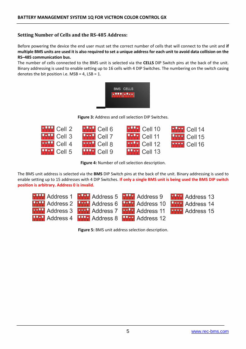
Setting Number of Cells and the RS-485 Address: Before powering the device the end user must set the correct number of cells that will connect to the unit and if multiple BMS units are used it is also required to set a unique address for each unit to avoid data collision on the RS–485 communication bus. The number of cells connected to the BMS unit is selected via the CELLS DIP Switch pins at the back of the unit. Binary addressing is used to enable setting up to 16 cells with 4 DIP Switches. The numbering on the switch casing denotes the bit position i.e. MSB = 4, LSB = 1.
Figure 3: Address and cell selection DIP Switches.
Figure 4: Number of cell selection description.
The BMS unit address is selected via the BMS DIP Switch pins at the back of the unit. Binary addressing is used to enable setting up to 15 addresses with 4 DIP Switches. If only a single BMS unit is being used the BMS DIP switch position is arbitrary. Address 0 is invalid.
Figure 5: BMS unit address selection description.

BATTERY MANAGEMENT SYSTEM 1Q FOR VICTRON COLOR CONTROL GX
6 www.rec-bms.com
BMS Unit cell Connector: Connect each cell to the BMS unit cell connector plug. Use silicon wires with cross section of 0.5 – 1mm2 ! Before inserting the cell connector check voltage level and polarity of each connection! ! When working on cells connections –the BMS’s cells connector should be unplugged otherwise the BMS may be damaged !
Figure 6: Battery pack to BMS connection.
BMS Unit Power Supply: BMS unit is always supplied from the 16-th cell connection pin. ! When less than 16 cells are used in the battery pack, an additional connection from the battery pack voltage (Pack +) to the 16-th cell connection pin should be made, as shown in Fig. 7 !
Figure 7: BMS unit power supply.
BATTERY MANAGEMENT SYSTEM 1Q FOR VICTRON COLOR CONTROL GX
7 www.rec-bms.com
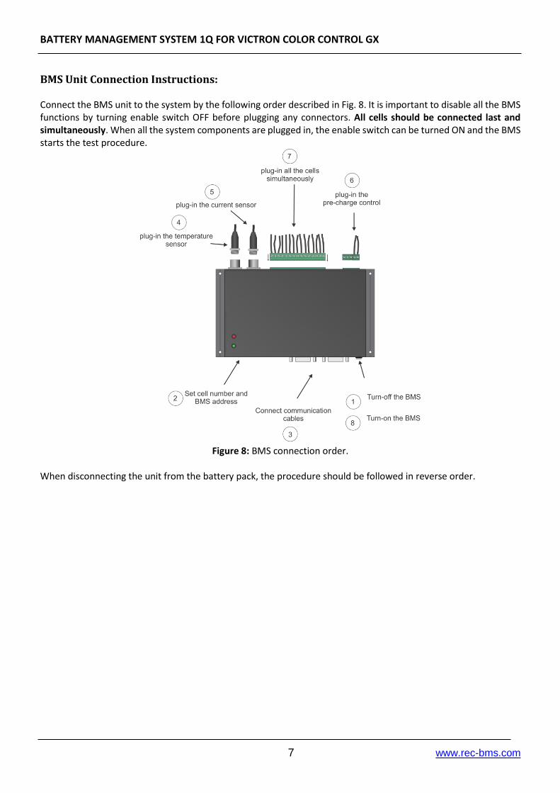
BMS Unit Connection Instructions: Connect the BMS unit to the system by the following order described in Fig. 8. It is important to disable all the BMS functions by turning enable switch OFF before plugging any connectors. All cells should be connected last and simultaneously. When all the system components are plugged in, the enable switch can be turned ON and the BMS starts the test procedure.
Figure 8: BMS connection order.
When disconnecting the unit from the battery pack, the procedure should be followed in reverse order.

BATTERY MANAGEMENT SYSTEM 1Q FOR VICTRON COLOR CONTROL GX
8 www.rec-bms.com
RS-485 Communication Protocol:
Figure 9: RS-485 DB9 connector front view.
Table 3: RS-485 DB9 connector pin designator.
Pin Designator
1 -
2 GND
3 B + TERMINATION 470 OHM
4 A + TERMINATION
5 -
6 +5V
7 -
8 -
9 -
Galvanically isolated RS-485 (EN 61558-1, EN 61558-2) serves for logging and changing BMS parameters. Dedicated PC BMS Control Software or another RS-485 device may be used for the communication. Messages are comprised as follows: STX, DA, SA, N, INSTRUCTION- 4 bytes, 16-bit CRC, ETX
STX start transmition <0x55> (always)
DA - destination address <0x01> to <0x10> (set as 6)
SA - sender address <0x00> (always 0)
N – number of sent bytes
INSTRUCTION – 4 bytes: RS-485 instruction set is described in table 4.A typical instruction consists of 4 ASCII characters followed by ‘?’ or ‘ ‘,’ xx.xx‘.
‘?’: the BMS returns the current parameter value
‘ ‘,’xx.xx‘. : sets the parameter value to xx.xx (float format) .
Example: 'C','M','A','X','?'/ 'C','M','A','X',' ','xxx'. ‘CMAX?’ – returns the value of the maximum cell voltage parameter
‘CMAX 3.2’– sets the maximum cell voltage to 3.2 V.
16-bit CRC, for the whole message except STX in ETX
ETX - end transmition <0xAA> (always)
Dataflow:
Bit rate: 56k
Data bits: 8
Stop bits: 1
Parity: None
Mode: Asynchronous
Little endian format when an array is sent

BATTERY MANAGEMENT SYSTEM 1Q FOR VICTRON COLOR CONTROL GX
9 www.rec-bms.com
Table 4: RS-485 instruction set.
INSTRUCTION DESCRIPTION BMS ANSWER
'*','I','D','N','?' Identification Answer “REC - BATERY MANAGEMENT SYSTEM”
'L','C','D','1','?' Main data
First answer is 28 – how many byte data will be sent and then data message follows as 7 float values: LCD1 [0] = min cell voltage, LCD1 [1] = max cell voltage, LCD1 [2] = current, LCD1 [3] = max temperature, LCD1 [4] = pack voltage, LCD1 [5] = SOC (state of charge) interval 0-1-> 1=100% and LCD1 [6] = SOH (state of health) interval 0-1-> 1=100%
'L','C','D','3','?' Main data
First answer is 8 – how many byte data will be sent and then data message follows as 8 byte values: LCD3 [0] = min cell BMS address, LCD3 [1] = min cell number, LCD3 [2] = max cell BMS address, LCD3 [3] = max cell number, LCD3 [4] = max temp. sens. BMS address, LCD3 [5] = max temp. sens. number, LCD3 [6] = Ah MSB, LCD3 [7] = Ah LSB
'C','E','L','L','?' Cell voltages BMS first responds with how many BMS units are connected, then it sends the values of the cells in float format
'P','T','E','M','?' Cell temperatures BMS first responds with how many BMS units are connected then it sends the values of the temperature sensors in float format
'R','I','N','T','?' Cells internal DC resistance BMS first responds with how many BMS units are connected then it sends the values in float format
'B','T','E','M','?' BMS temperature BMS first responds with value 1, then it sends the values of the BMS temperature sensor in float format
'E','R','R','O','?' Error
First answer is 4 – how many byte data will be sent and then data message follows as 4 byte values: ERRO [0] = 0 – no error, 1 – error ERRO [1] = BMS unit ERRO [2] = error number (1-13) in ERRO [3] = number of the cell, temp. sensor where the error occurred
'B','V','O','L', '?'/ 'B','V','O','L', ' ','xxx'
Cell END balancing Returns float voltage [V]
'C','M','A','X','?'/ 'C','M','A','X',' ','xxx'
Max allowed cell voltage Returns float voltage [V]
'M','A','X','H', '?'/ 'M','A','X','H', ' ','xxx'
Max allowed cell voltage hysteresis
Returns float voltage [V]
'C','M','I','N', '?'/ 'C','M','I','N', ' ','xxx'
Min allowed cell voltage Returns float voltage [V]
'M','I','N','H', '?'/ 'M','I','N','H', ' ','xxx'
Min allowed cell voltage hysteresis
Returns float voltage [V]
'T','M','A','X', '?'/ 'T','M','A','X', ' ','xxx'
Maximum allowed cell temperature
Returns float temperature [°C]
BATTERY MANAGEMENT SYSTEM 1Q FOR VICTRON COLOR CONTROL GX
10 www.rec-bms.com
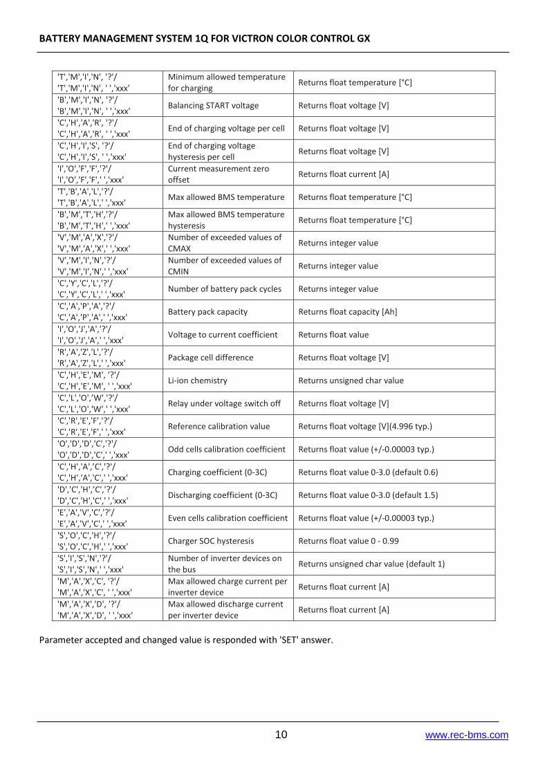
'T','M','I','N', '?'/ 'T','M','I','N', ' ','xxx'
Minimum allowed temperature for charging
Returns float temperature [°C]
'B','M','I','N', '?'/ 'B','M','I','N', ' ','xxx'
Balancing START voltage Returns float voltage [V]
'C','H','A','R', '?'/ 'C','H','A','R', ' ','xxx'
End of charging voltage per cell Returns float voltage [V]
'C','H','I','S', '?'/ 'C','H','I','S', ' ','xxx'
End of charging voltage hysteresis per cell
Returns float voltage [V]
'I','O','F','F','?'/ 'I','O','F','F',' ','xxx'
Current measurement zero offset
Returns float current [A]
'T','B','A','L','?'/ 'T','B','A','L',' ','xxx'
Max allowed BMS temperature Returns float temperature [°C]
'B','M','T','H','?'/ 'B','M','T','H',' ','xxx'
Max allowed BMS temperature hysteresis
Returns float temperature [°C]
'V','M','A','X','?'/ 'V','M','A','X',' ','xxx'
Number of exceeded values of CMAX
Returns integer value
'V','M','I','N','?'/ 'V','M','I','N',' ','xxx'
Number of exceeded values of CMIN
Returns integer value
'C','Y','C','L','?'/ 'C','Y','C','L',' ','xxx'
Number of battery pack cycles Returns integer value
'C','A','P','A','?'/ 'C','A','P','A',' ','xxx'
Battery pack capacity Returns float capacity [Ah]
'I','O','J','A','?'/ 'I','O','J','A',' ','xxx'
Voltage to current coefficient Returns float value
'R','A','Z','L','?'/ 'R','A','Z','L',' ','xxx'
Package cell difference Returns float voltage [V]
'C','H','E','M', '?'/ 'C','H','E','M', ' ','xxx'
Li-ion chemistry Returns unsigned char value
'C','L','O',’W','?'/ 'C','L','O','W',' ','xxx'
Relay under voltage switch off Returns float voltage [V]
'C','R','E','F','?'/ 'C','R','E','F',' ','xxx'
Reference calibration value Returns float voltage [V](4.996 typ.)
'O','D','D','C','?'/ 'O','D','D','C',' ','xxx'
Odd cells calibration coefficient Returns float value (+/-0.00003 typ.)
'C','H','A',’C','?'/ 'C','H','A','C',' ','xxx'
Charging coefficient (0-3C) Returns float value 0-3.0 (default 0.6)
'D','C','H',’C','?'/ 'D','C','H','C',' ','xxx'
Discharging coefficient (0-3C) Returns float value 0-3.0 (default 1.5)
'E','A','V','C','?'/ 'E','A','V','C',' ','xxx'
Even cells calibration coefficient Returns float value (+/-0.00003 typ.)
'S','O','C','H','?'/ 'S','O','C','H',' ','xxx'
Charger SOC hysteresis Returns float value 0 - 0.99
'S','I','S','N','?'/ 'S','I','S','N',' ','xxx'
Number of inverter devices on the bus
Returns unsigned char value (default 1)
'M','A','X','C', '?'/ 'M','A','X','C', ' ','xxx'
Max allowed charge current per inverter device
Returns float current [A]
'M','A','X','D', '?'/ 'M','A','X','D', ' ','xxx'
Max allowed discharge current per inverter device
Returns float current [A]
Parameter accepted and changed value is responded with 'SET' answer.
BATTERY MANAGEMENT SYSTEM 1Q FOR VICTRON COLOR CONTROL GX
11 www.rec-bms.com
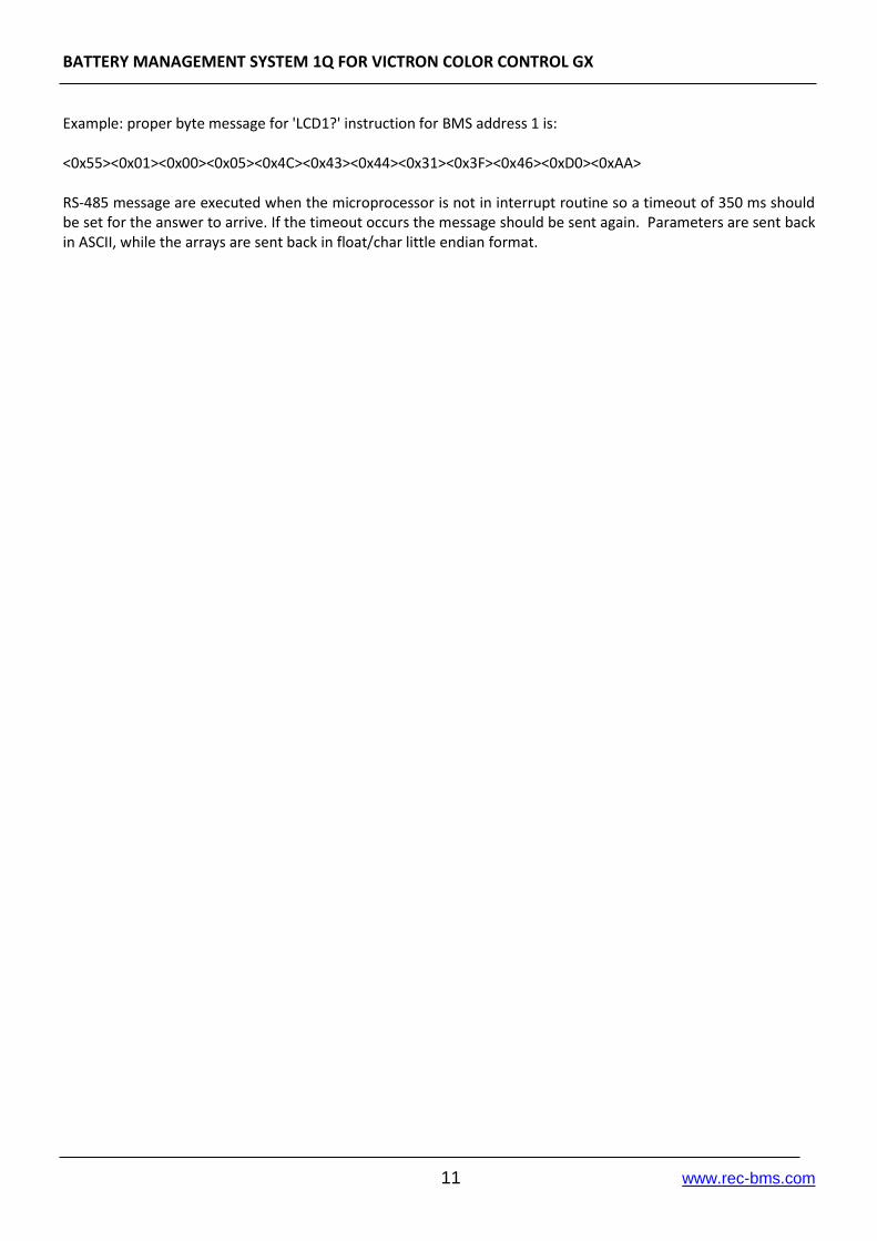
Example: proper byte message for 'LCD1?' instruction for BMS address 1 is: <0x55><0x01><0x00><0x05><0x4C><0x43><0x44><0x31><0x3F><0x46><0xD0><0xAA> RS-485 message are executed when the microprocessor is not in interrupt routine so a timeout of 350 ms should be set for the answer to arrive. If the timeout occurs the message should be sent again. Parameters are sent back in ASCII, while the arrays are sent back in float/char little endian format.

BATTERY MANAGEMENT SYSTEM 1Q FOR VICTRON COLOR CONTROL GX
12 www.rec-bms.com
CAN Communication Protocol:
Figure 10: CAN DB9 connector front view. Table 5: CAN DB9 connector pin designator.
Pin Designator
1 TERMINATION
2 CANL +TERMINATION
3 GND
4
5 -
6 GND
7 CANH
8 -
9
Table 6: CAN RJ45 connector pin designator.
Pin Designator
1 -
2 -
3 GND
4 -
5 -
6 -
7 CANH + TERMINATION*
8 CANL + TERMINATION* * Termination plug
Bit-rate: 250 kbs Split termination used inside BMS - terminate pins 1 and 2 if CAN is not in use to prevent BMS reset. Additional RJ45 connector with 120 Ohms across CANL and CANH should be used for the end device on the CAN bus for termination. 11-bit TX identifiers: 0x351, 0x355, 0x356, 0x35A, 0x35B, 0x35E, 0x370 8 byte message structure: Table 7: CAN message 0x351 structure description.
Byte Description Type Property
1 Charge voltage low byte Unsigned integer LSB = 0.1 V
2 Charge voltage high byte
3 Max charging current low byte Signed integer LSB = 0.1 A
4 Max charging current high byte
5 Max discharging current low byte Signed integer LSB = 0.1 A
6 Max discharging current high byte
7 Discharge voltage low byte Unsigned integer LSB = 0.1 V
8 Discharge voltage high byte

BATTERY MANAGEMENT SYSTEM 1Q FOR VICTRON COLOR CONTROL GX
13 www.rec-bms.com
Table 8: CAN message 0x355 structure description.
Byte Description Type Property
1 SOC low byte Unsigned integer LSB = 1 %
2 SOC high byte
3 SOH low byte Unsigned integer LSB = 1 %
4 SOH high byte
5 SOC high definition low byte Unsigned integer LSB = 0.01 %
6 SOC high definition high byte
Table 9: CAN message 0x356 structure description.
Byte Description Type Property
1 Battery voltage low byte Signed integer LSB = 0.01 V
2 Battery voltage high byte
3 Battery current low byte Signed integer LSB = 0.1 A
4 Battery current high byte
5 Battery temperature low byte Signed integer LSB = 0.1 °C
6 Battery temperature high byte
Table 10: CAN message 0x35A structure description.
Byte Description Type Property
1 Alarm byte 1 Unsigned char
Bit orientated Alarm structure 2 Alarm byte 2 Unsigned char
3 Alarm byte 3 Unsigned char
4 Alarm byte 4 Unsigned char
5 Warning byte 1 Unsigned char
Bit orientated Warning structure 6 Warning byte 2 Unsigned char
7 Warning byte 3 Unsigned char
8 Warning byte 4 Unsigned char
Table 10: CAN message 0x35E structure description.
Byte Description Type Data/ASCII Property
1 Data byte 1 Unsigned char 82/R
Manufacturer Name REC-BMS
2 Data byte 2 Unsigned char 69/E
3 Data byte 3 Unsigned char 67/C
4 Data byte 4 Unsigned char 45/-
5 Data byte 5 Unsigned char 66/B
6 Data byte 6 Unsigned char 77/M
7 Data byte 7 Unsigned char 83/S
8 Data byte 8 Unsigned char 0/
Table 11: CAN message 0x370 structure description.
Byte Description Type Data/ASCII Property
1 Description Unsigned char 82/R
Battery/BMS Name REC-1Q
2 Data byte 1 Unsigned char 69/E
3 Data byte 2 Unsigned char 67/C
4 Data byte 3 Unsigned char 45/-
5 Data byte 4 Unsigned char 81/Q
6 Data byte 5 Unsigned char 49/1
7 Data byte 6 Unsigned char 0/
8 Data byte 7 Unsigned char 0/
CAN messages are sent each measuring cycle with 150 ms interval between.

BATTERY MANAGEMENT SYSTEM 1Q FOR VICTRON COLOR CONTROL GX
14 www.rec-bms.com
BMS Unit Start Procedure: When the BMS is turned ON it commences the test procedure. BMS checks if the user tries to upload a new firmware by turning on the Power LED. After the timeout the Red error LED turns on to signal the system’s test procedure. The procedure starts by testing the balancing switches, the BMS address and cells number, temperature sensor/s detection, self calibration and EEPROM memory parameters. The test completes in 7 seconds. In case of no Errors the red LED turns off and the BMS unit starts working in normal mode. If an error is detected a sound alarm/blinking red LED signal will notify the user. Each error is coded to a number. The most common errors at system startup are listed below.
Error 6 = improper DIP switch setting. In case of Address=0 or cell number <4, error 6 informs the user to properly set the DIP switches. BMS has to be turned off before the pins are changed.
Error 8 = temperature sensor not detected.
Error 10 = reference failure
Error 15 =balancing transistor failure An overview of all possible system errors is presented in the System Error Indication Section.
Pre-charge Circuit: Pre-charge circuit is used to charge the input capacitors of inverters. When the BMS turns the internal relay, battery voltage starts to charge the capacitors via 66 Ohm power resistors inside the pre-charge circuit. After 4 s, the contactor is turned ON. When the BMS encounters an error and the contactor should be turned OFF, it sends an Alarm massage via CAN bus so the inverters can start the Stand-by or Turn-off procedure prior of contactor turning OFF. Figure 11 below shows how to connect the pre-charge circuit in the system.
Figure 11: Pre-charge circuit connection schematics.
BATTERY MANAGEMENT SYSTEM 1Q FOR VICTRON COLOR CONTROL GX
15 www.rec-bms.com
BMS Unit LED Indication: Power LED (green) is turned on in 2 s intervals, if the BMS is powered. When the battery pack is fully charged Power LED turns ON without blinking. Error LED (red) is turned on in case of system error. Number of Error LED blinks/sound alarm indicates Error number.
Cell voltage Measurement: Cell voltages are measured every second. The cell measurement algorithm performs several measurements to digitally filter the influence of 50, 60, 100 and 120 Hz sinus signal. Each cell voltage is measured after the balancing fuse, in case the fuse blows BMS signals error 10 to notify the user.
BMS Cell Balancing: Cells are balanced passively by discharging each cell through a 4.3 Ω power resistor. Since the balancing resistors dissipate heat an additional temperature measurement inside the enclosure of the BMS unit is performed to prevent overheating the integrated circuits. If the BMS temperature rises above the set threshold, balancing is stopped. BMS error 5 is indicated until the temperature drops under the set hysteresis value.
Balancing START Voltage: If errors 2, 4, 5, 8, 10, 12 are not present, the charging current is above 0.2 A and at least one cell’s voltage rises above the balancing start voltage threshold the BMS initiates the balancing algorithm. The algorithm calculates a weighted cell voltage average which takes into account the internal dc resistance of each cell. On the basis of the calculated average the BMS determines which cell will be balanced.
Balancing END Voltage: If errors 2, 4, 5, 8, 10, 12 are not present, the cells above balancing END voltage are balanced regardless the battery pack current.
Cell internal DC Resistance Measurement: Cell internal DC resistance is measured as a ratio of a voltage change and current change in two sequential measurement cycles. If the absolute current change is above 15 A, cells internal resistance is calculated. Moving average is used to filter out voltage spikes errors.
Battery Pack Temperature Measurement: Battery pack temperatures are measured by Dallas DS18B20 digital temperature sensors. Up to three sensors can be used in parallel in a single connector. The BMS should be turned off before adding additional sensors. If the temperature sensors wiring is placed near the power lines, shielded cables should be used.
BATTERY MANAGEMENT SYSTEM 1Q FOR VICTRON COLOR CONTROL GX
16 www.rec-bms.com
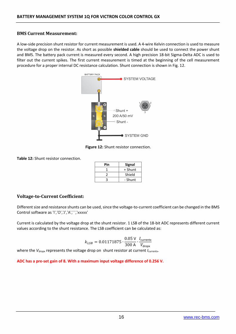
BMS Current Measurement: A low-side precision shunt resistor for current measurement is used. A 4-wire Kelvin connection is used to measure the voltage drop on the resistor. As short as possible shielded cable should be used to connect the power shunt and BMS. The battery pack current is measured every second. A high precision 18-bit Sigma-Delta ADC is used to filter out the current spikes. The first current measurement is timed at the beginning of the cell measurement procedure for a proper internal DC resistance calculation. Shunt connection is shown in Fig. 12.
Figure 12: Shunt resistor connection.
Table 12: Shunt resistor connection.
Pin Signal
1 + Shunt
2 Shield
3 - Shunt
Voltage-to-Current Coefficient: Different size and resistance shunts can be used, since the voltage-to-current coefficient can be changed in the BMS Control software as 'I','O','J','A',' ','xxxxx' Current is calculated by the voltage drop at the shunt resistor. 1 LSB of the 18-bit ADC represents different current values according to the shunt resistance. The LSB coefficient can be calculated as:
𝑘𝐿𝑆𝐵 = 0.01171875 ∙0.05 V
300 A∙𝐼currentx
𝑉dropx
where the Vdropx represents the voltage drop on shunt resistor at current Icurrentx. ADC has a pre-set gain of 8. With a maximum input voltage difference of 0.256 V.

BATTERY MANAGEMENT SYSTEM 1Q FOR VICTRON COLOR CONTROL GX
17 www.rec-bms.com
Battery Pack SOC Determination: SOC is determined by integrating the charge in-to or out of the battery pack(coulomb counting method). Different Li-ion chemistries may be selected: Table 13: Li-ion chemistry designators.
Number Type
1 Li-Po Kokam High power
2 Li-Po Kokam High capacity
3 Winston/Thunder-Sky/GWL LiFePO4
4 A123
5 Li-ion NMC/ LiMn2O4
Temperature and power correction coefficient are taken into consideration calculatin the SOC. Li-Po chemistry algorithms have an additional voltage to SOC slow regulation loop inside the algorithm. Actual cell capacity is recalculated by the number of the charging cycles as pointed out in the manufacturer’s datasheet. When BMS is connected to the battery pack, SOC is set to 50 % by default. SOC is reset to 100 % at the end of the first charging cycle. SOC can be set to a desired value through the RS-485 communication protocol by the 'S','O','C','S',' ','x.xx' instruction (0.0-1.0). When BMS is connected to the battery pack for the first time, SOC is set to 50 %. SOC is reset to 100 % at the end of charging. Charging cycle is added when the coulomb counter reaches battery pack’s capacity. Coulomb counter is reset when the BMS is turned off.

BATTERY MANAGEMENT SYSTEM 1Q FOR VICTRON COLOR CONTROL GX
18 www.rec-bms.com
Battery Pack’s Charging Algorithm: The communication between the REC BMS and the Victron CCGX is established through the CAN bus. All the parameters that control the charging/discharging behavior are calculated by the BMS and transmitted to the CCGX unit in every measurement cycle. The charging current is controlled by the Maximum charging current parameter. It’s calculated as Charging Coefficient('C','H','A',’C') x Battery capacity. The parameter has an upper limit which is defined as Maximum Charging Current per Device ('M','A','X',’C') x Number of Devices ('S','I','S',’N'). When any cell reaches the voltage interval between Balance Voltages Start and Balance Voltage End, the charging current starts to ramp down to 1.1 A x Number of Devices until the last cell rises to the End of Charge Voltage. At that point the Maximum charging voltage is set to Number of cells x (End of Charge Voltage per cell - end of charge hysteresis per cell) and the charger is disabled also via the BMS I/O interface. End of Charge, SOC hysteresis and End of charging cell voltage hysteresis prevent unwanted switching. SOC is calibrated to 100 % and Power LED lights ON 100 %. Charger turn-off can also be caused by some of the systems errors (See System Errors indication chapter). SOC is calibrated to 96 % at the 0.502 x value between Balance Voltages Start and Balance Voltage End. In case BMS is not able to control the MPPT directly (MPPT should be set to charge when the remote is in short), a small signal relay can be used to amplify the signal. MPPT should be programmed with its own charging curve set as End of charge voltage x number of cells.
Figure 13: External signal relay with 12 V coil connection schematics.

BATTERY MANAGEMENT SYSTEM 1Q FOR VICTRON COLOR CONTROL GX
19 www.rec-bms.com
Battery Pack’s Discharging Algorithm: Calculated maximum discharging current is sent to the Color Control GX by CAN communication in every measurement cycle. When the BMS starts/recovers from the error or from Discharging SOC hysteresis, maximum allowed discharging current is set. It is calculated as discharging coefficient ('D','C','H',’C') x Battery capacity. If this value is higher than maximum discharging current per device ('M','A','X',’D') x number of devices ('S','I','S',’N'), maximum discharging current is decreased to this value. When the lowest open circuit voltage cell is discharged bellow the set threshold 'C','L','O',’W', the maximum discharging current starts to decrease down to 0.05 C (5 % of Capacity in A). After decreasing down, maximum allowed discharging current is set to 0 A. SOC is reset to 3 % and Discharging SOC hysteresis is set to 5 %. If the cell discharges bellow Minimum Cell voltage ('C','M','I','N'), BMS signals Error 2 and SOC is reset to 0 %. If the Charger/inverter is connected to the grid maximum allowed discharge current is drawn from the grid. Otherwise 100 % load current is drawn from the battery until maximum allowed discharging current is set to 0 A.
Victron System Configuration: Inverter/charger configuration Download and install VE Configuration tools from: https://www.victronenergy.com/support-and-downloads/software. Connect your computer to a VE.Bus product. MK3-USB interface and RJ45 UTP cable are required. Computer with internet connection will automatically download correct driver. Update all components to latest firmware, follow instructions on: https://www.victronenergy.com/live/updating_firmware:updating_ve.bus_products https://www.victronenergy.com/live/ccgx:firmware_updating Color Control settings: Update CCGX to 2.11 or higher. Connect Color Control GX (CCGX) with other devices (MPPT, Multis). Open Settings menu and select System setup. Change:
- Battery monitor to REC BMS in CAN-bus.
In Settings menu select Services, CAN-bus profile and click on VE.Can & CAN-bus BMS (250 kbit/s). CCGX settings are automatically saved when you change it. Grid set point is not fixed value and can be modified for user needs.
BATTERY MANAGEMENT SYSTEM 1Q FOR VICTRON COLOR CONTROL GX
20 www.rec-bms.com
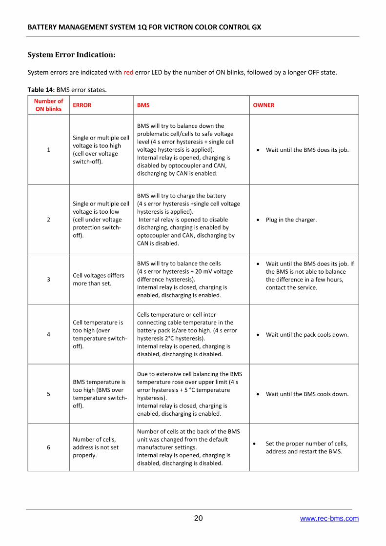
System Error Indication: System errors are indicated with red error LED by the number of ON blinks, followed by a longer OFF state. Table 14: BMS error states.
Number of ON blinks
ERROR BMS OWNER
1
Single or multiple cell voltage is too high (cell over voltage switch-off).
BMS will try to balance down the problematic cell/cells to safe voltage level (4 s error hysteresis + single cell voltage hysteresis is applied). Internal relay is opened, charging is disabled by optocoupler and CAN, discharging by CAN is enabled.
Wait until the BMS does its job.
2
Single or multiple cell voltage is too low (cell under voltage protection switch-off).
BMS will try to charge the battery (4 s error hysteresis +single cell voltage hysteresis is applied). Internal relay is opened to disable discharging, charging is enabled by optocoupler and CAN, discharging by CAN is disabled.
Plug in the charger.
3 Cell voltages differs more than set.
BMS will try to balance the cells (4 s error hysteresis + 20 mV voltage difference hysteresis). Internal relay is closed, charging is enabled, discharging is enabled.
Wait until the BMS does its job. If the BMS is not able to balance the difference in a few hours, contact the service.
4
Cell temperature is too high (over temperature switch-off).
Cells temperature or cell inter-connecting cable temperature in the battery pack is/are too high. (4 s error hysteresis 2°C hysteresis). Internal relay is opened, charging is disabled, discharging is disabled.
Wait until the pack cools down.
5
BMS temperature is too high (BMS over temperature switch-off).
Due to extensive cell balancing the BMS temperature rose over upper limit (4 s error hysteresis + 5 °C temperature hysteresis). Internal relay is closed, charging is enabled, discharging is enabled.
Wait until the BMS cools down.
6 Number of cells, address is not set properly.
Number of cells at the back of the BMS unit was changed from the default manufacturer settings. Internal relay is opened, charging is disabled, discharging is disabled.
Set the proper number of cells, address and restart the BMS.

BATTERY MANAGEMENT SYSTEM 1Q FOR VICTRON COLOR CONTROL GX
21 www.rec-bms.com
7
The temperature is too low for charging (under temperature charging disable).
If cells are charged at temperatures lower than operating temperature range, cells are aging much faster than they normally would, so charging is disabled (2 °C temperature hysteresis). Internal relay is opened, charging is disabled, discharging is enabled.
Wait until the battery’s temperature rises to usable range.
8 Temperature sensor error.
Temperature sensor is un-plugged or not working properly (4 s error hysteresis). Internal relay is opened, charging is disabled, discharging is disabled.
Turn-off BMS unit and try to re-plug the temp. sensor. If the BMS still signals error 8, contact the service. The temperature sensors should be replaced.
9 Communication error.
RS-485 Master-Slave communication only.
10 Cell in short circuit or BMS measurement error.
Single or multiple cell voltage is close to zero or out of range, indicating a blown fuse, short circuit or measuring failure (20 s error hysteresis + 10 mV voltage difference hysteresis). Internal relay is opened, charging is disabled, discharging is disabled.
Turn-off the BMS and check the cells connection to the BMS and fuses. Restart the BMS.
If the same error starts to signal again contact the service.
11 Main relay is in short circuit.
If the main relay should be opened and current is not zero or positive, the BMS signals error 11. When the error is detected, the BMS tries to un-shorten the main relay by turning it ON and OFF for three times. Internal relay is opened, charging is disabled, discharging is disabled.
Restart the BMS unit. If the same error starts to signal again contact the service.
12 Error measuring current.
Current sensor is disconnected or not working properly. Internal relay is opened, charging is disabled, discharging is disabled.
Turn-off the BMS and check the sensor connections, re-plug the current sensor connector. Turn BMS back ON. If the BMS still signals error 12, contact the service.
13 Wrong cell chemistry selected.
In some application the chemistry pre-set is compulsory. Internal relay is opened, charging is disabled, discharging is disabled.
Use PC Control Software to set proper cell chemistry.
14 Wrong EEPROM value.
EMI or other interference caused EEPOM data to change. Default settings are programmed-in. Contactor is closed, charging is enabled, discharging is enabled.
Use PC interface to set proper parameters.
15 Balancing transistors failure
Single or multiple transistors for balancing failure detection Contactor is closed, charging is enabled, discharging is enabled.
Restart the BMS unit. If the same error starts to signal again contact the service.
BATTERY MANAGEMENT SYSTEM 1Q FOR VICTRON COLOR CONTROL GX
22 www.rec-bms.com
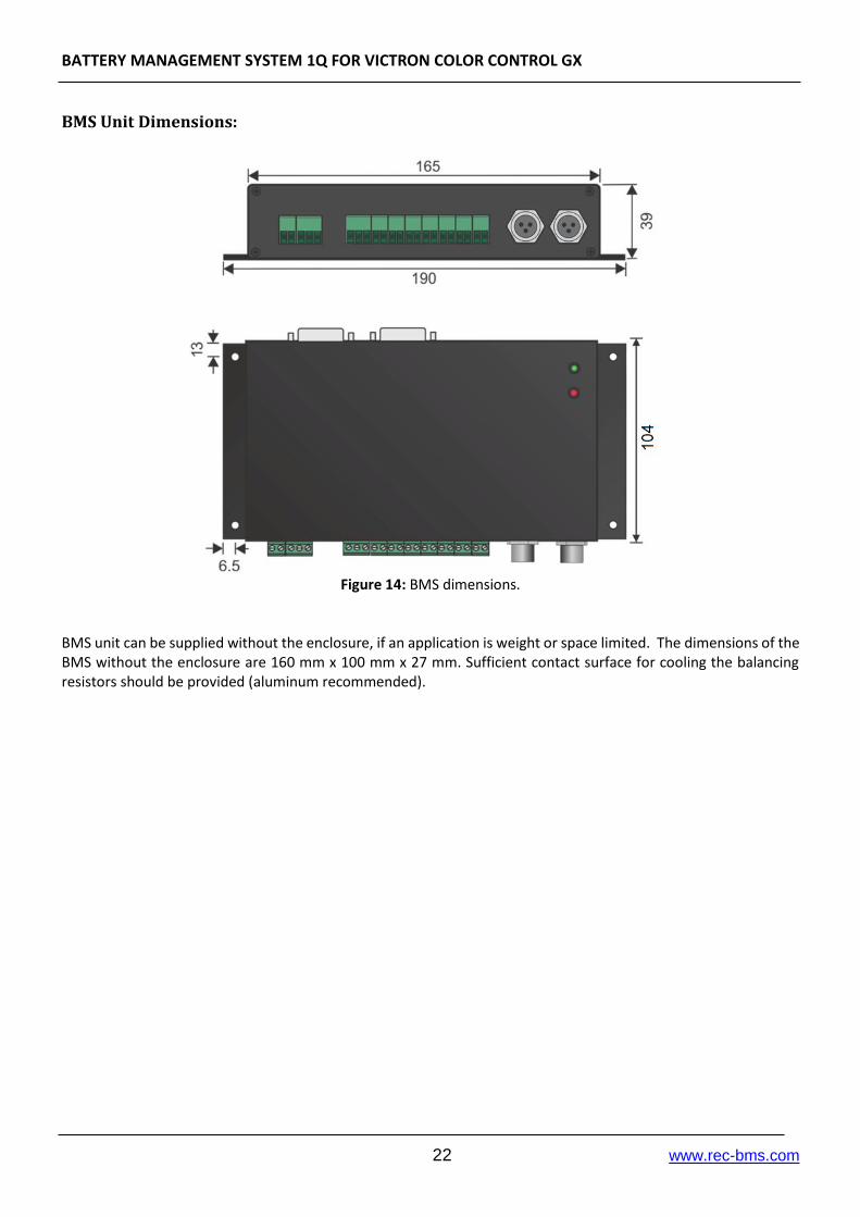
BMS Unit Dimensions:
Figure 14: BMS dimensions.
BMS unit can be supplied without the enclosure, if an application is weight or space limited. The dimensions of the BMS without the enclosure are 160 mm x 100 mm x 27 mm. Sufficient contact surface for cooling the balancing resistors should be provided (aluminum recommended).