VIBRO KIT...VIBRO KIT TECHNICAL REFERENCE MANUAL 3.3 Vibro-kit parts description 3.3.1 Encoders...
29
VIBRO KIT TECHNICAL REFERENCE MANUAL VIBRO KIT V20-2
Transcript of VIBRO KIT...VIBRO KIT TECHNICAL REFERENCE MANUAL 3.3 Vibro-kit parts description 3.3.1 Encoders...
VIBRO KIT TECHNICAL REFERENCE MANUAL VIBRO KIT V20-2
VIBRO KIT TECHNICAL REFERENCE MANUAL
1 Table of contents 1 Table of contents 2
2 About this document 4 2.1 Legend 4
3 Technical data 5 3.1 Introduction 5 3.2 Scope of supply 5 3.3 Vibro-kit parts description 6
3.3.1 Encoders 6 3.3.2 Optical sensor below taped disk 7 3.3.3 Front panel 8 3.3.4 Back panel 9 3.3.5 Couplings 11
4 Possibilities of use 12 4.1 Super-counters 12 4.2 FFT analyzer 15 4.3 Order tracking 17 4.4 Balancing 18 4.5 Torsional vibration 20
5 Specifications HW v1.3 22
6 User interface FW v1.9 22 6.1 Manual mode 22 6.2 Ramp mode 23 6.3 Analog in mode 24 6.4 PWM in mode 24
7 Warranty information 25 7.1 Calibration 25 7.2 Support 25 7.3 Service/repair 25 7.4 Restricted Rights 25 7.5 Printing History 26 7.6 Copyright 26 7.7 Trademarks 26
8 Safety instructions 26 8.1 Safety symbols in the manual 26 8.2 General Safety Instructions 26
8.2.1 Environmental Considerations 27 8.2.2 Product End-of-Life Handling 27 8.2.3 System and Components Recycling 27 8.2.4 General safety and hazard warnings for all Dewesoft systems 27
VIBRO KIT V20-1 2/29

VIBRO KIT TECHNICAL REFERENCE MANUAL
9 Documentation version history 29
VIBRO KIT V20-1 3/29
VIBRO KIT TECHNICAL REFERENCE MANUAL
2 About this document
2.1 Legend The following symbols and formats will be used throughout the document.
Important It gives you important information about the subject. Please read carefully!
Hint It gives you a hint or provides additional information about a subject.
Example Gives you an example of a specific subject.
VIBRO KIT V20-1 4/29
VIBRO KIT TECHNICAL REFERENCE MANUAL
3 Technical data
3.1 Introduction
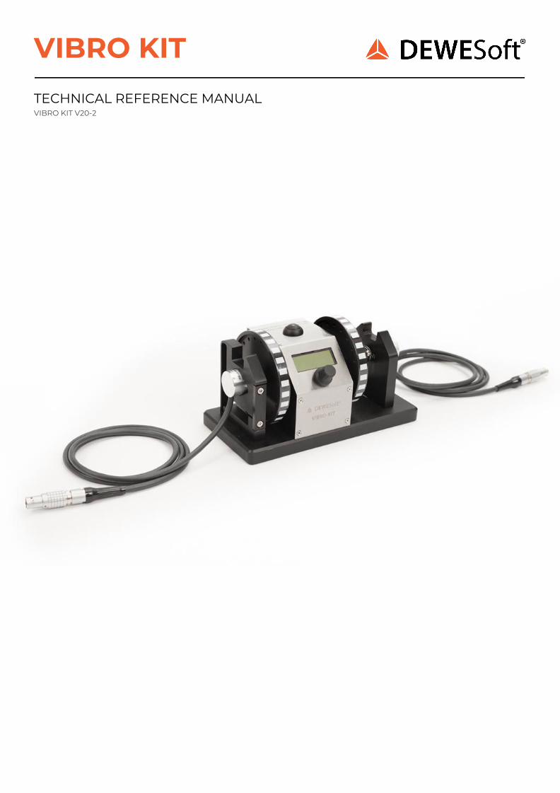
The new VIBRO-KIT is a compact tool for simulating rotating machinery measurements. It is meant for demonstrations or educational purposes such as in a lab or university. It provides a playground for almost unlimited experiments.
It's made of solid aluminum. It’s built of a small electric motor with a simple control panel, two bearings, two optical strip-tape angle sensors, two encoders and two different couplings on each side. One is rigid and the other is made of spring.
The RPM can be controlled manually by a turn knob, or you can completely define ramps, cycles, etc. with the built-in display.
Furthermore, an external analog voltage (or even PWM signal) can be used to control the RPM.
Functionalities:
● Manual RPM control (turn knob, display) ● Definable ramps (runup, coast down, hold time and multiple cycles) ● RPM control by external voltage (e.g. step curve) ● External PWM input ● Different angle sensors (2 optical strip tape, 2 Encoders)
3.2 Scope of supply
** Power supply adapter is not included
VIBRO KIT V20-1 5/29
Type Quantity Description
Vibro-kit 1 Vibro-kit unit
BNC-BNC 1 BNC to BNC connector cable of 1,2 m
L1B7m-BNC 2 7 pin LEMO to BNC connector cable of 0,6 m
BALANCING SCREWS kit Screws 10pcs M3x4, 10pcs M3x6, 10 pcs M3x8, 10pcs M3x10 Nuts 20pcs M3x2.3
VIBRO KIT TECHNICAL REFERENCE MANUAL
3.3 Vibro-kit parts description
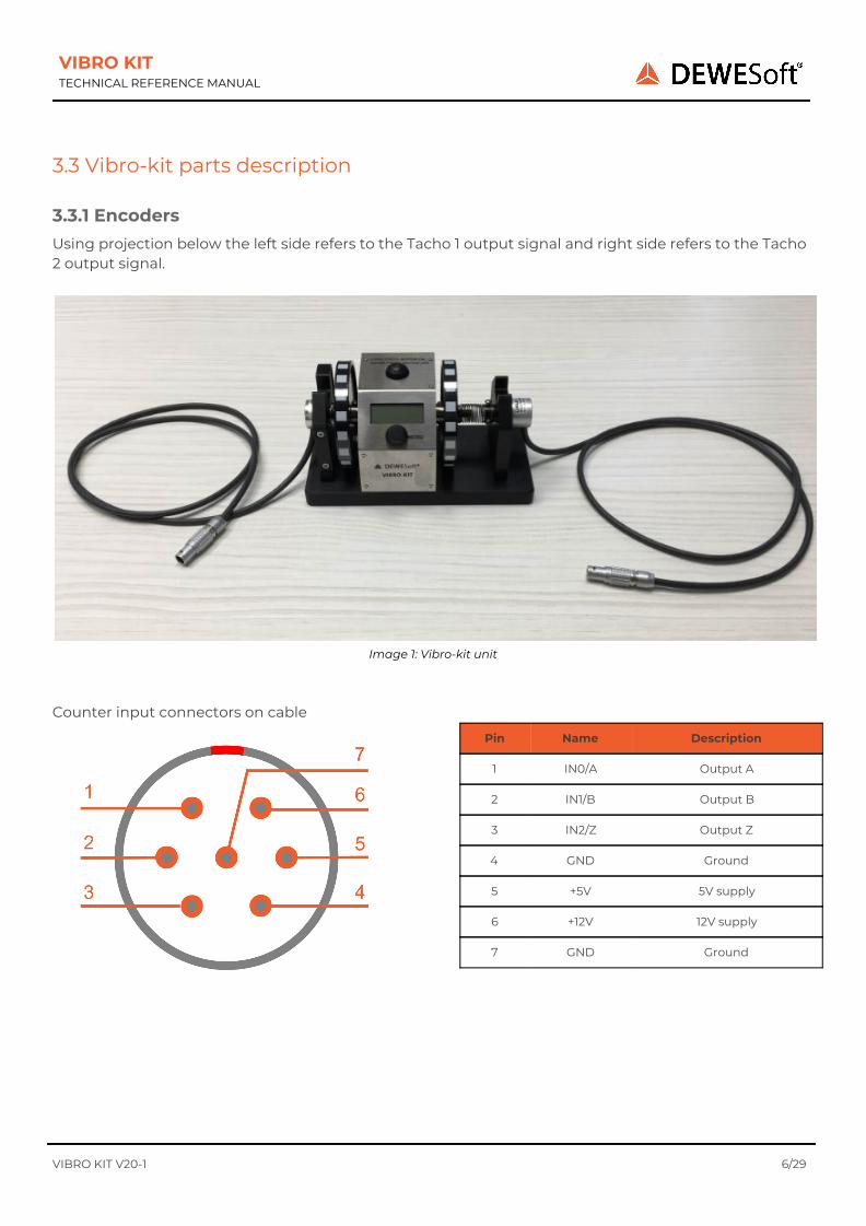
3.3.1 Encoders Using projection below the left side refers to the Tacho 1 output signal and right side refers to the Tacho 2 output signal.
Image 1: Vibro-kit unit
Counter input connectors on cable
VIBRO KIT V20-1 6/29
Pin Name Description
1 IN0/A Output A
2 IN1/B Output B
3 IN2/Z Output Z
4 GND Ground
5 +5V 5V supply
6 +12V 12V supply
7 GND Ground

VIBRO KIT TECHNICAL REFERENCE MANUAL
3.3.2 Optical sensor below taped disk Integrated optical sensor on the bottom side of the chassis for measuring signal of the striped tape on the rotating disc which is affixed on the shaft of the motor. Please see chapter 3.3.1. Encoders to define which sensor has Tacho 1 output and which has Tacho 2 output.
Image 2: Vibro-kit unit
VIBRO KIT V20-1 7/29
VIBRO KIT TECHNICAL REFERENCE MANUAL
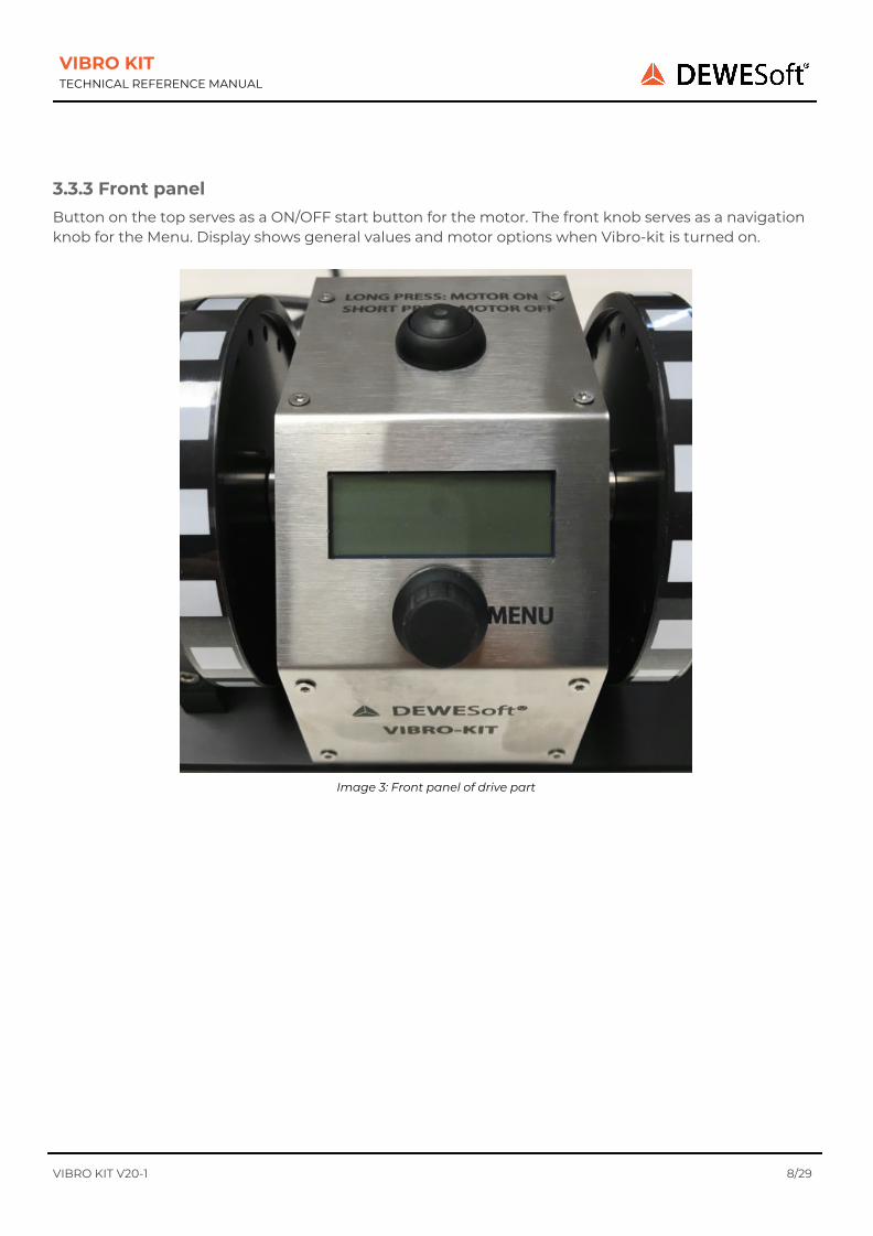
3.3.3 Front panel Button on the top serves as a ON/OFF start button for the motor. The front knob serves as a navigation knob for the Menu. Display shows general values and motor options when Vibro-kit is turned on.
Image 3: Front panel of drive part
VIBRO KIT V20-1 8/29

VIBRO KIT TECHNICAL REFERENCE MANUAL
3.3.4 Back panel
Image 4: Back panel of drive part
Power supply connector
VIBRO KIT V20-1 9/29
Pin Name Description
1 V + Power supply 12V...36V
2 V - Ground

VIBRO KIT TECHNICAL REFERENCE MANUAL
Control IN connector
BNC female connector
Using an input signal if you want to control the RPM of an internal motor with voltage signal.
Tacho 1 Out
BNC female connector
Measuring an output signal from an optical sensor that is integrated below the rotating disk.
Tacho 2 Out
BNC female connector
Measuring an output signal from an optical sensor that is integrated below the rotating disk.
VIBRO KIT V20-1 10/29
VIBRO KIT TECHNICAL REFERENCE MANUAL
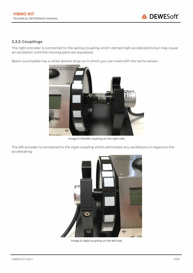
3.3.5 Couplings The right encoder is connected to the spring coupling which damps high accelerations but may cause an oscillation until the moving parts are equalized. Black round plate has a white dotted strap on it which you can read with the tacho sensor.
Image 5: Flexible coupling on the right side
The left encoder is connected to the rigid coupling which eliminates any oscillations in regard to the accelerating.
Image 6: Rigid coupling on the left side
VIBRO KIT V20-1 11/29
VIBRO KIT TECHNICAL REFERENCE MANUAL
4 Possibilities of use
4.1 Super-counters
Additional equipment: SIRIUS with at least one CNT module (ACC+, …).
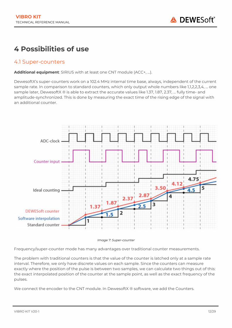
DewesoftX’s super-counters work on a 102.4 MHz internal time base, always, independent of the current sample rate. In comparison to standard counters, which only output whole numbers like 1,1,2,2,3,4, … one sample later, DewesoftX ® is able to extract the accurate values like 1.37, 1.87, 2.37, … fully time- and amplitude-synchronized. This is done by measuring the exact time of the rising edge of the signal with an additional counter.
Image 7: Super-counter
Frequency/super-counter mode has many advantages over traditional counter measurements.
The problem with traditional counters is that the value of the counter is latched only at a sample rate interval. Therefore, we only have discrete values on each sample. Since the counters can measure exactly where the position of the pulse is between two samples, we can calculate two things out of this: the exact interpolated position of the counter at the sample point, as well as the exact frequency of the pulses.
We connect the encoder to the CNT module. In DewesoftX ® software, we add the Counters.
VIBRO KIT V20-1 12/29
VIBRO KIT TECHNICAL REFERENCE MANUAL
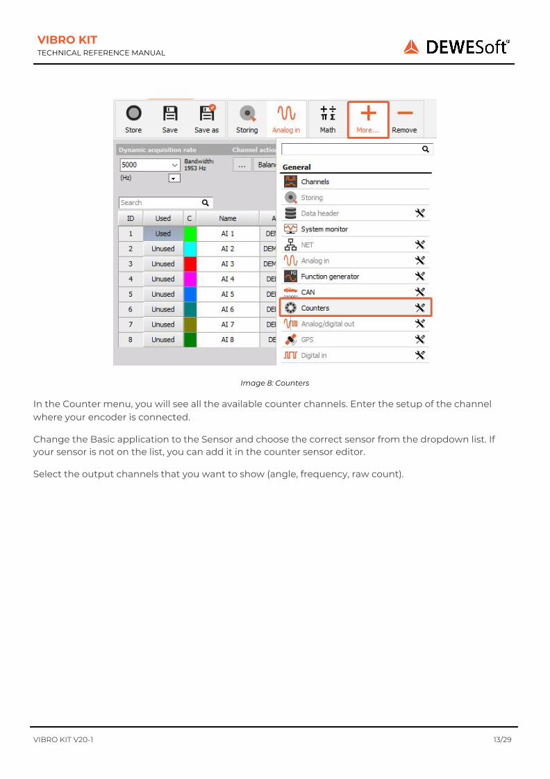
Image 8: Counters
In the Counter menu, you will see all the available counter channels. Enter the setup of the channel where your encoder is connected.
Change the Basic application to the Sensor and choose the correct sensor from the dropdown list. If your sensor is not on the list, you can add it in the counter sensor editor.
Select the output channels that you want to show (angle, frequency, raw count).
VIBRO KIT V20-1 13/29
VIBRO KIT TECHNICAL REFERENCE MANUAL
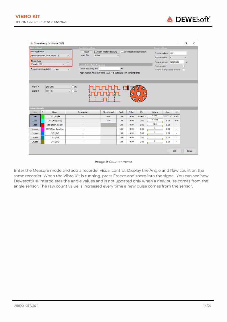
Image 9: Counter menu
Enter the Measure mode and add a recorder visual control. Display the Angle and Raw count on the same recorder. When the Vibro Kit is running, press Freeze and zoom into the signal. You can see how DewesoftX ® interpolates the angle values and is not updated only when a new pulse comes from the angle sensor. The raw count value is increased every time a new pulse comes from the sensor.
VIBRO KIT V20-1 14/29
VIBRO KIT TECHNICAL REFERENCE MANUAL
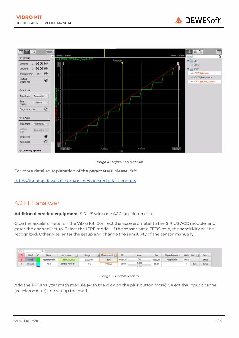
Image 10: Signals on recorder
For more detailed explanation of the parameters, please visit:
https://training.dewesoft.com/online/course/digital-counters
4.2 FFT analyzer
Additional needed equipment: SIRIUS with one ACC, accelerometer.
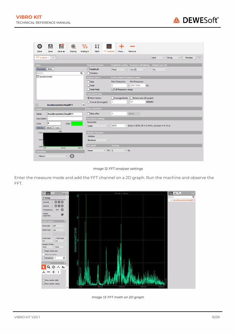
Glue the accelerometer on the Vibro Kit. Connect the accelerometer to the SIRIUS ACC module, and enter the channel setup. Select the IEPE mode – if the sensor has a TEDS chip, the sensitivity will be recognized. Otherwise, enter the setup and change the sensitivity of the sensor manually.
Image 11: Channel setup
Add the FFT analyzer math module (with the click on the plus button More). Select the input channel (accelerometer) and set up the math.
VIBRO KIT V20-1 15/29
VIBRO KIT TECHNICAL REFERENCE MANUAL
Image 12: FFT analyser settings
Enter the measure mode and add the FFT channel on a 2D graph. Run the machine and observe the FFT.
Image 13: FFT math on 2D graph
VIBRO KIT V20-1 16/29

VIBRO KIT TECHNICAL REFERENCE MANUAL
On the FFT graph, you can show the markers and how FFT behaves with different parameters in the setup. For an explanation of all the parameter visit:
https://training.dewesoft.com/online/course/fft-spectral-analysis
4.3 Order tracking
Additional needed equipment: SIRIUS with one ACC and one CNT module, accelerometer.
Glue the accelerometer on the Vibro Kit and connect it to the ACC module. Connect encoder to the CNT module. Open channel setup and set the acceleration sensor to IEPE mode and enter the correct sensitivity. Add an Order tracking module.
Image 14: Order tracking settings
Select the vibration and the frequency input channel. Detailed description of all the parameters can be found here: https://training.dewesoft.com/online/course/order-tracking
Enter the measure mode, and run the machine slowly from 0 RPM to 3000 RPM.
VIBRO KIT V20-1 17/29

VIBRO KIT TECHNICAL REFERENCE MANUAL
The order tracking module creates a display with two 3D graphs to show order and FFT waterfalls, two 2D graphs to show the order harmonics and phase of the harmonics and a digital meter to monitor the RPMs of the machine.
Image 15: Order tracking screen
4.4 Balancing
Additional needed equipment: SIRIUS with one ACC (single plane balancing) or two ACC modules (dual plane balancing), accelerometer (single plane balancing) or two accelerometers (dual plane balancing), additional screws for balancing the rotor.
Select the input channel (vibration) and define the frequency source (counters, analog sensor, RPM channel). Balancing procedures should be done at constant RPMs.
VIBRO KIT V20-1 18/29

VIBRO KIT TECHNICAL REFERENCE MANUAL
Image 16: Balancing settings
Balancing is a step-by-step procedure. First, you need to perform the initial run, to get the initial unbalance vector. After that, you attach a trial weight, perform a trial run to get another unbalance vector. From those two unbalanced vectors, we calculate the correction mass that has to be added and the angle at which this should be added. You can perform as many steps as you wish.
Image 17: Rotor balancer screen
For more detailed explanation of balancing parameters and settings, please visit: https://training.dewesoft.com/online/course/balancing
VIBRO KIT V20-1 19/29
VIBRO KIT TECHNICAL REFERENCE MANUAL
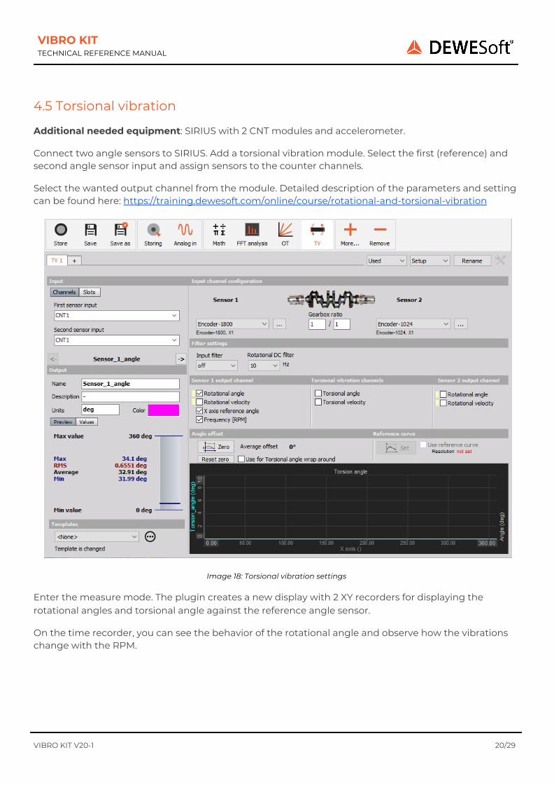
4.5 Torsional vibration
Additional needed equipment: SIRIUS with 2 CNT modules and accelerometer.
Connect two angle sensors to SIRIUS. Add a torsional vibration module. Select the first (reference) and second angle sensor input and assign sensors to the counter channels.
Select the wanted output channel from the module. Detailed description of the parameters and setting can be found here: https://training.dewesoft.com/online/course/rotational-and-torsional-vibration
Image 18: Torsional vibration settings
Enter the measure mode. The plugin creates a new display with 2 XY recorders for displaying the rotational angles and torsional angle against the reference angle sensor.
On the time recorder, you can see the behavior of the rotational angle and observe how the vibrations change with the RPM.
VIBRO KIT V20-1 20/29

VIBRO KIT TECHNICAL REFERENCE MANUAL
Image 19: Torsional vibration screen
VIBRO KIT V20-1 21/29
VIBRO KIT TECHNICAL REFERENCE MANUAL
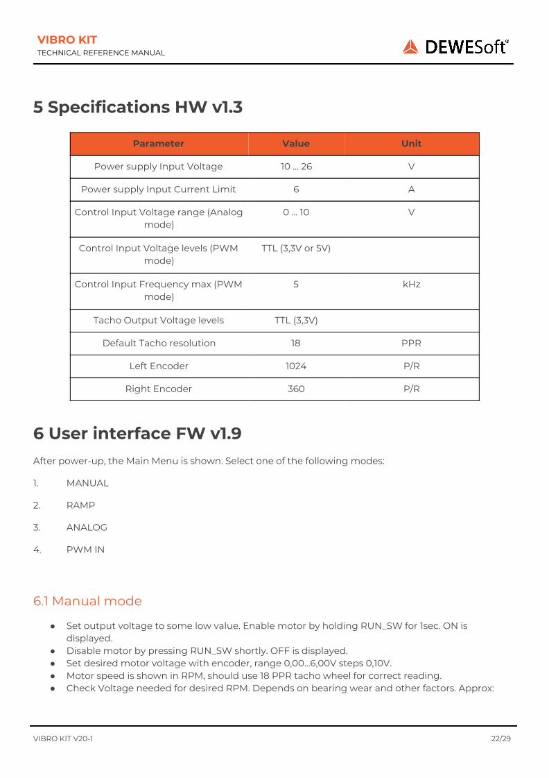
5 Specifications HW v1.3
6 User interface FW v1.9 After power-up, the Main Menu is shown. Select one of the following modes:
1. MANUAL
2. RAMP
3. ANALOG
4. PWM IN
6.1 Manual mode
● Set output voltage to some low value. Enable motor by holding RUN_SW for 1sec. ON is displayed.
● Disable motor by pressing RUN_SW shortly. OFF is displayed. ● Set desired motor voltage with encoder, range 0,00…6,00V steps 0,10V. ● Motor speed is shown in RPM, should use 18 PPR tacho wheel for correct reading. ● Check Voltage needed for desired RPM. Depends on bearing wear and other factors. Approx:
VIBRO KIT V20-1 22/29
Parameter Value Unit
Power supply Input Voltage 10 … 26 V
Power supply Input Current Limit 6 A
Control Input Voltage range (Analog mode)
0 … 10 V
Control Input Voltage levels (PWM mode)
TTL (3,3V or 5V)
Control Input Frequency max (PWM mode)
5 kHz
Tacho Output Voltage levels TTL (3,3V)
Default Tacho resolution 18 PPR
Left Encoder 1024 P/R
Right Encoder 360 P/R

VIBRO KIT TECHNICAL REFERENCE MANUAL
● To exit Manual mode, disable motor first, then hold ENC_SW for 1sec. ● Enabling the motor after the motor voltage has been set too high may result in input current
limiter tripping, resulting in system power down. Disconnect and reconnect power supply to restart.
6.2 Ramp mode
Image 10: Ramp
● Refer to the above chart for parameter explanation and set up parameters. ● Set number of cycles. Use 0 for infinite loop.
VIBRO KIT V20-1 23/29
Motor Voltage (V) Motor Speed (RPM)
1,00 470
2,00 1100
3,00 1800
4,00 2300
5,00 3000
VIBRO KIT TECHNICAL REFERENCE MANUAL
● Enable motor and start Ramp cycling by holding RUN_SW for 1 sec. Number of cycles remaining
is now shown in bold font. Arrow is also shown in bold and shows the current step of ramp cycle. Parameters are updated live during runtime to show progress. Editing of parameters is disabled.
● Disable motor and stop Ramp cycling by pressing RUN_SW. Display returns to non-bold font and initial parameters are shown. Editing of parameters is enabled.
● When the number of cycles to be done is reached, Ramp is automatically stopped and motor disabled.
● To exit Ramp mode, hold ENC_SW for 1sec while Ramp is not cycling.
6.3 Analog in mode
● Connect external voltage source to Control Input. ● Optionally set Acceleration rate (ACCEL) if input voltage is expected to be rising too quickly,
which would cause the motor to accelerate too quickly, leading to input current limiter tripping. ● Enable motor by holding RUN_SW for 1sec. ON is displayed. ● Input voltage is scaled 1:1 to motor output voltage. ● Regardless of input voltage, motor voltage is limited to max. 6,00V. ● Disable motor by pressing RUN_SW shortly. OFF is displayed. ● To exit Analog In mode, disable motor first, then hold ENC_SW for 1sec.
6.4 PWM in mode
● Connect external PWM source to Control Input. Allowed voltage levels range is from 3V TTL to 36V.
● Optionally set Acceleration rate (ACCEL) if input duty cycle is expected to be changing too quickly, which would cause the motor accelerate too quickly, leading to input current limiter tripping.
● Enable motor by holding RUN_SW for 1sec. ON is displayed. ● Duty cycle is measured, maximum PWM frequency is 5kHz. Duty cycle values 0%...100% are
scaled to motor voltage 0,00 … 10,00V. ● Regardless of input duty cycle, motor voltage is limited to max. 6,00V. ● Disable motor by pressing RUN_SW shortly. OFF is displayed. ● To exit PWM In mode, disable motor first, then hold ENC_SW for 1sec.
VIBRO KIT V20-1 24/29
VIBRO KIT TECHNICAL REFERENCE MANUAL
7 Warranty information Notice The information contained in this document is subject to change without notice. Note: Dewesoft d.o.o. shall not be liable for any errors contained in this document. Dewesoft MAKES NO WARRANTIES OF ANY KIND WITH REGARD TO THIS DOCUMENT, WHETHER EXPRESS OR IMPLIED. DEWESOFT SPECIFICALLY DISCLAIMS THE IMPLIED WARRANTIES OF MERCHANTABILITY AND FITNESS FOR A PARTICULAR PURPOSE. Dewesoft shall not be liable for any direct, indirect, special, incidental, or consequential damages, whether based on contract, tort, or any other legal theory, in connection with the furnishing of this document or the use of the information in this document. The copy of the specific warranty terms applicable to your Dewesoft product and replacement parts can be obtained from your local sales and service office. To find a local dealer for your country, please visit https://dewesoft.com/support/distributors. 7.1 Calibration Every instrument needs to be calibrated at regular intervals. The standard norm across nearly every industry is annual calibration. Before your Dewesoft data acquisition system is delivered, it is calibrated. Detailed calibration reports for your Dewesoft system can be requested. We retain them for at least one year, after system delivery. 7.2 Support Dewesoft has a team of people ready to assist you if you have any questions or any technical difficulties regarding the system. For any support please contact your local distributor first or Dewesoft directly. Dewesoft d.o.o. Gabrsko 11a 1420 Trbovlje Slovenia Europe Tel.: +386 356 25 300 Web: http://www.dewesoft.com Email: [email protected] The telephone hotline is available Monday to Friday from 07:00 to 16:00 CET (GMT +1:00)
7.3 Service/repair The team of Dewesoft also performs any kind of repairs to your system to assure a safe and proper operation in the future. For information regarding service and repairs please contact your local distributor first or Dewesoft directly on https://dewesoft.com/support/rma-service.
7.4 Restricted Rights Use Slovenian law for duplication or disclosure. Dewesoft d.o.o. Gabrsko 11a, 1420 Trbovlje, Slovenia / Europe.
VIBRO KIT V20-1 25/29
VIBRO KIT TECHNICAL REFERENCE MANUAL
7.5 Printing History Version 2.0.0, Revision 217 Released 2015 Last changed: 23. July 2018 at 16:54. 7.6 Copyright Copyright © 2015-2019 Dewesoft d.o.o. This document contains information that is protected by copyright. All rights are reserved. Reproduction, adaptation, or translation without prior written permission is prohibited, except as allowed under the copyright laws. All trademarks and registered trademarks are acknowledged to be the property of their owners. 7.7 Trademarks We take pride in our products and we take care that all key products and technologies are registered as trademarks all over the world. The Dewesoft name is a registered trademark. Product families (KRYPTON, SIRIUS, DSI, DS-NET) and technologies (DualCoreADC, SuperCounter, GrandView) are registered trademarks as well. When used as the logo or as part of any graphic material, the registered trademark sign is used as a part of the logo. When used in text representing the company, product or technology name, the ® sign is not used. The Dewesoft triangle logo is a registered trademark but the ® sign is not used in the visual representation of the triangle logo.
8 Safety instructions Your safety is our primary concern! Please be safe! 8.1 Safety symbols in the manual
Warning Calls attention to a procedure, practice, or condition that could cause body injury or death Caution Calls attention to a procedure, practice, or condition that could possibly cause damage to equipment or permanent loss of data.
8.2 General Safety Instructions
Warning
The following general safety precautions must be observed during all phases of operation, service, and repair of this product. Failure to comply with these precautions or with specific warnings elsewhere in this manual violates safety standards of design, manufacture, and intended use of the product. Dewesoft GmbH assumes no liability for the customer’s failure to comply with these requirements. All accessories shown in this document are available as an option and will not be shipped as standard parts.
VIBRO KIT V20-1 26/29

VIBRO KIT TECHNICAL REFERENCE MANUAL
8.2.1 Environmental Considerations Information about the environmental impact of the product.
8.2.2 Product End-of-Life Handling Observe the following guidelines when recycling a Dewesoft system:
8.2.3 System and Components Recycling Production of these components required the extraction and use of natural resources. The substances contained in the system could be harmful to your health and to the environment if the system is improperly handled at its end of life! Please recycle this product in an appropriate way to avoid unnecessary pollution of the environment and to keep natural resources.
This symbol indicates that this system complies with the European Union’s requirements according to Directive 2002/96/EC on waste electrical and electronic equipment (WEEE). Please find further information about recycling on the Dewesoft web site www.dewesoft.com Restriction of Hazardous Substances This product has been classified as Monitoring and Control equipment and is outside the
scope of the 2002/95/EC RoHS Directive. However, we take care of our environment and the product is lead-free.
8.2.4 General safety and hazard warnings for all Dewesoft systems The safety of the operator and the unit depend on following these rules.
● Use this system under the terms of the specifications only to avoid any possible danger. ● Read your manual before operating the system. ● Observe local laws when using the instrument. ● DO NOT touch internal wiring! ● DO NOT use a higher supply voltage than specified! ● Use only original plugs and cables for harnessing. ● You may not connect higher voltages than rated to any connectors. ● The power cable and connector serve as Power-Breaker. The cable must not exceed 3 meters,
the disconnect function must be possible without tools. ● Maintenance must be executed by qualified staff only. ● During the use of the system, it might be possible to access other parts of a more comprehensive
system. Please read and follow the safety instructions provided in the manuals of all other components regarding warning and security advice for using the system.
● With this product, only use the power cable delivered or defined for the host country. ● DO NOT connect or disconnect sensors, probes or test leads, as these parts are connected to a
voltage supply unit. ● Ground the equipment: For Safety Class 1 equipment (equipment having a protective earth
terminal), a non-interruptible safety earth ground must be provided from the mains power source to the product input wiring terminals.
● Please note the characteristics and indicators of the system to avoid fire or electric shocks. Before connecting the system, please read the corresponding specifications in the product manual carefully.
VIBRO KIT V20-1 27/29
VIBRO KIT TECHNICAL REFERENCE MANUAL
● The inputs must not unless otherwise noted (CATx identification), be connected to the main
circuit of category II, III and IV. ● The power cord separates the system from the power supply. Do not block the power cord, since
it has to be accessible for the users. ● DO NOT use the system if equipment covers or shields are removed. ● If you assume the system is damaged, get it examined by authorized personnel only. ● Adverse environmental conditions are Moisture or high humidity Dust, flammable gases, fumes
or dissolver Thunderstorm or thunderstorm conditions (except assembly PNA) Electrostatic fields, etc.
● The measurement category can be adjusted depending on the module configuration. ● Any other use than described above may damage your system and is attended with dangers like
short-circuiting, fire or electric shocks. ● The whole system must not be changed, rebuilt or opened. ● DO NOT operate damaged equipment: Whenever it is possible that the safety protection
features built into this product have been impaired, either through physical damage, excessive moisture, or any other reason, REMOVE POWER and do not use the product until the safe operation can be verified by service-trained personnel. If necessary, return the product to the Dewesoft sales and service office for service and repair to ensure that safety features are maintained.
● If you assume a more riskless use is not provided anymore, the system has to be rendered inoperative and should be protected against inadvertent operation. It is assumed that a more riskless operation is not possible anymore if the system is damaged obviously or causes strange noises. The system does not work anymore. The system has been exposed to long storage in adverse environments. The system has been exposed to heavy shipment strain.
● Warranty void if damages caused by disregarding this manual. For consequential damages, NO liability will be assumed!
● Warranty void if damage to property or persons caused by improper use or disregarding the safety instructions.
● Unauthorized changing or rebuilding the system is prohibited due to safety and permission reasons (CE).
● Be careful with voltages >25 VAC or >35 VDC! These voltages are already high enough in order to get a perilous electric shock by touching the wiring.
● The product heats during operation. Make sure there is adequate ventilation. Ventilation slots must not be covered!
● Only fuses of the specified type and nominal current may be used. The use of patched fuses is prohibited.
● Prevent using metal bare wires! Risk of short circuit and fire hazard! ● DO NOT use the system before, during or shortly after a thunderstorm (risk of lightning and high
energy over-voltage). An advanced range of applications under certain conditions is allowed with therefore designed products only. For details please refer to the specifications.
● Make sure that your hands, shoes, clothes, the floor, the system or measuring leads, integrated circuits and so on, are dry.
● DO NOT use the system in rooms with flammable gases, fumes or dust or in adverse environmental conditions.
● Avoid operation in the immediate vicinity of high magnetic or electromagnetic fields, transmitting antennas or high-frequency generators, for exact values please refer to enclosed specifications.
● Use measurement leads or measurement accessories aligned with the specification of the system only. Fire hazard in case of overload!
VIBRO KIT V20-1 28/29
VIBRO KIT TECHNICAL REFERENCE MANUAL
● Do not switch on the system after transporting it from a cold into a warm room and vice versa.
The thereby created condensation may damage your system. Acclimatize the system unpowered to room temperature.
● Do not disassemble the system! There is a high risk of getting a perilous electric shock. Capacitors still might be charged, even if the system has been removed from the power supply.
● The electrical installations and equipment in industrial facilities must be observed by the security regulations and insurance institutions.
● The use of the measuring system in schools and other training facilities must be observed by skilled personnel.
● The measuring systems are not designed for use in humans and animals. ● Please contact a professional if you have doubts about the method of operation, safety or the
connection of the system. ● Please be careful with the product. Shocks, hits and dropping it from already- lower level may
damage your system. ● Please also consider the detailed technical reference manual as well as the security advice of the
connected systems. ● This product has left the factory in safety-related flawlessness and in proper condition. In order to
maintain this condition and guarantee safety use, the user has to consider the security advice and warnings in this manual.
EN 61326-3-1:2008 IEC 61326-1 applies to this part of IEC 61326 but is limited to systems and equipment for industrial applications intended to perform safety functions as defined in IEC 61508 with SIL 1-3. The electromagnetic environments encompassed by this product family standard are industrial, both indoor and outdoor, as described for industrial locations in IEC 61000-6-2 or defined in 3.7 of IEC 61326-1. Equipment and systems intended for use in other electromagnetic environments, for example, in the process industry or in environments with potentially explosive atmospheres, are excluded from the scope of this product family standard, IEC 61326-3-1. Devices and systems according to IEC 61508 or IEC 61511 which are considered as “operationally well-tried”, are excluded from the scope of IEC 61326-3-1. Fire-alarm and safety-alarm systems, intended for the protection of buildings, are excluded from the scope of IEC 61326-3-1.
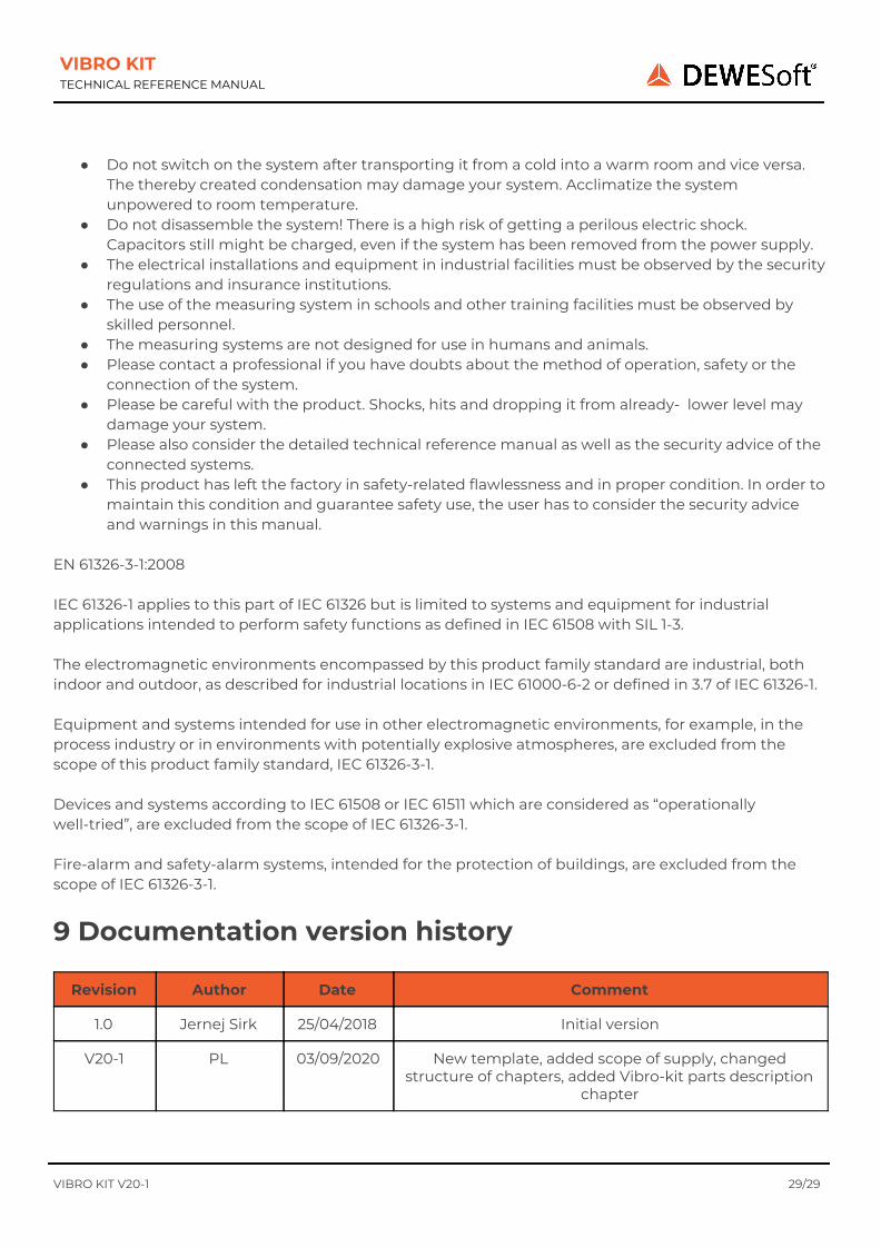
9 Documentation version history
VIBRO KIT V20-1 29/29
Revision Author Date Comment
1.0 Jernej Sirk 25/04/2018 Initial version
V20-1 PL 03/09/2020 New template, added scope of supply, changed structure of chapters, added Vibro-kit parts description
chapter