VIBRAPHONE AMPLIFICATION SYSTEM - K&K Sound · 2015-12-01 · VIBRAPHONE AMPLIFICATION SYSTEM...
6
92798 Cape Arago Hwy, Coos Bay, OR 97420 | 541-888-3517 | Toll Free 1-800-867-6863 | kksound.com VIBRAPHONE AMPLIFICATION SYSTEM Installing the Piezo-Ceramic Amplification System Note: This manual refers primarily to the vibraphone. Simply apply the same procedures to the marimba or xylophone if needed. 1. Place the bars upside-down on a table. With the white tone bars (F-F), put the low bars to the right side. With the black notes (F#-D#), position the low bars to the left side. 2. Mark a line on the bars corresponding to how the string would be threaded. Make sure you mark the OPPOSITE side of the damper end! Follow the picture below. This line serves to display the nodal points where the transducers will be attached. 3. With golden or silver galvanized or lacquered bars you need to remove the galvanization layer/coating on the spots where the pickups are going to be attached. Use the supplied sandpaper to sand down to the metal or wood. (This step is not necessary with “Musser Kelon” or fiberglass bars.) Sand a round area of about ¾” (20mm) diameter on the center of the marked line (see fig. 2 and 3). 4. After sanding, it is very important to clean all the sanded spots with rubbing alcohol or, even better, with acetone. Repeat this process several times until everything is absolutely clean. 5. Apply super glue to the metal side of the transducer. Spread the liquid over the entire surface with the tip of the tube. Note: Use a substantial amount of glue; the excess should ooze out on the edges to ensure a strong bond. Also apply superglue around the first 1/8” (3 mm) of cable where it connects to the pickup (see below, fig. 1). 6. Press the transducer to the marked point on each bar. Use the eraser end of the supplied pencil to gently apply pressure for 30 seconds. The exact positions of the pickups are shown in fig. 2 and 3 (below).
Transcript of VIBRAPHONE AMPLIFICATION SYSTEM - K&K Sound · 2015-12-01 · VIBRAPHONE AMPLIFICATION SYSTEM...
92798 Cape Arago Hwy, Coos Bay, OR 97420 | 541-888-3517 | Toll Free 1-800-867-6863 | kksound.com
VIBRAPHONE AMPLIFICATION SYSTEM
Installing the Piezo-Ceramic Amplification System Note: This manual refers primarily to the vibraphone. Simply apply the same procedures to the marimba or xylophone if needed. 1. Place the bars upside-down on a table. With the white tone bars (F-F), put the low bars to the right side. With the black notes (F#-D#), position the low bars to the left side. 2. Mark a line on the bars corresponding to how the string would be threaded. Make sure you mark the OPPOSITE side of the damper end! Follow the picture below. This line serves to display the nodal points where the transducers will be attached.
3. With golden or silver galvanized or lacquered bars you need to remove the galvanization layer/coating on the spots where the pickups are going to be attached. Use the supplied sandpaper to sand down to the metal or wood. (This step is not necessary with “Musser Kelon” or fiberglass bars.) Sand a round area of about ¾” (20mm) diameter on the center of the marked line (see fig. 2 and 3). 4. After sanding, it is very important to clean all the sanded spots with rubbing alcohol or, even better, with acetone. Repeat this process several times until everything is absolutely clean.
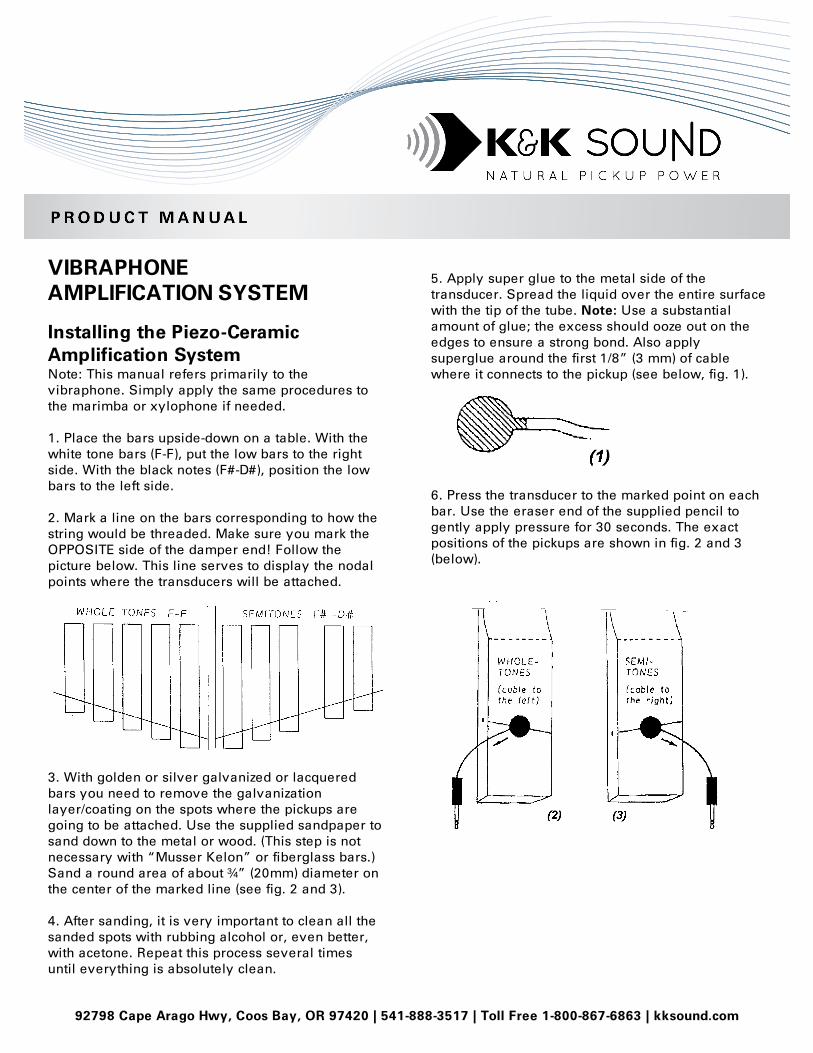
5. Apply super glue to the metal side of the transducer. Spread the liquid over the entire surface with the tip of the tube. Note: Use a substantial amount of glue; the excess should ooze out on the edges to ensure a strong bond. Also apply superglue around the first 1/8” (3 mm) of cable where it connects to the pickup (see below, fig. 1).
6. Press the transducer to the marked point on each bar. Use the eraser end of the supplied pencil to gently apply pressure for 30 seconds. The exact positions of the pickups are shown in fig. 2 and 3 (below).
2
Spread the oozing-out glue all around the edge of the transducer with the tip of the glue tube (fig. 4) while you hold the pickup down with the eraser. After you finish gluing all pickups, allow the glue to set for at least 30 minutes before you move the bars. Note: The superglue will
take even longer to completely set because it was applied quite thickly. However, our tests show that 30 minutes of drying time is enough to allow moving and testing the bars. Just be careful and do not play them hard yet. 7. Attach the whole tone and half tone collecting rails to the outside of the corresponding front and back frame rail of the vibraphone with 2 screws each. Tip: You can use a clamp to temporarily hold the collecting rail in place while you pre-drill the 2 mounting holes and fasten the screws. The distance between the bottom of the bars and the top of the collecting rails should be about 2” (5cm). For example, on a Musser M55 the low edge of the collecting rail ends up perfectly flush with the low edge of the frame rail. If you have a split-rail system (4 rails with hangers) or a custom system with hangers on the rails, you do not have to screw on the rails. With split rails, the upper and lower rails are connected with the supplied short TRSS (stereo ¼” plugs) connector cables. 8. Carefully place the bars on your instrument and plug the transducers into the corresponding sockets in the collecting rails. Carefully bend the pickup cables in a way so that they are not touching anything (the underside of the bar, the posts between the bars, the vibraphone frame or the rail). This has to be done every time you plug the pickups in at setup! A pickup cable that vibrates against something will buzz and it will be heard through the amplification system.
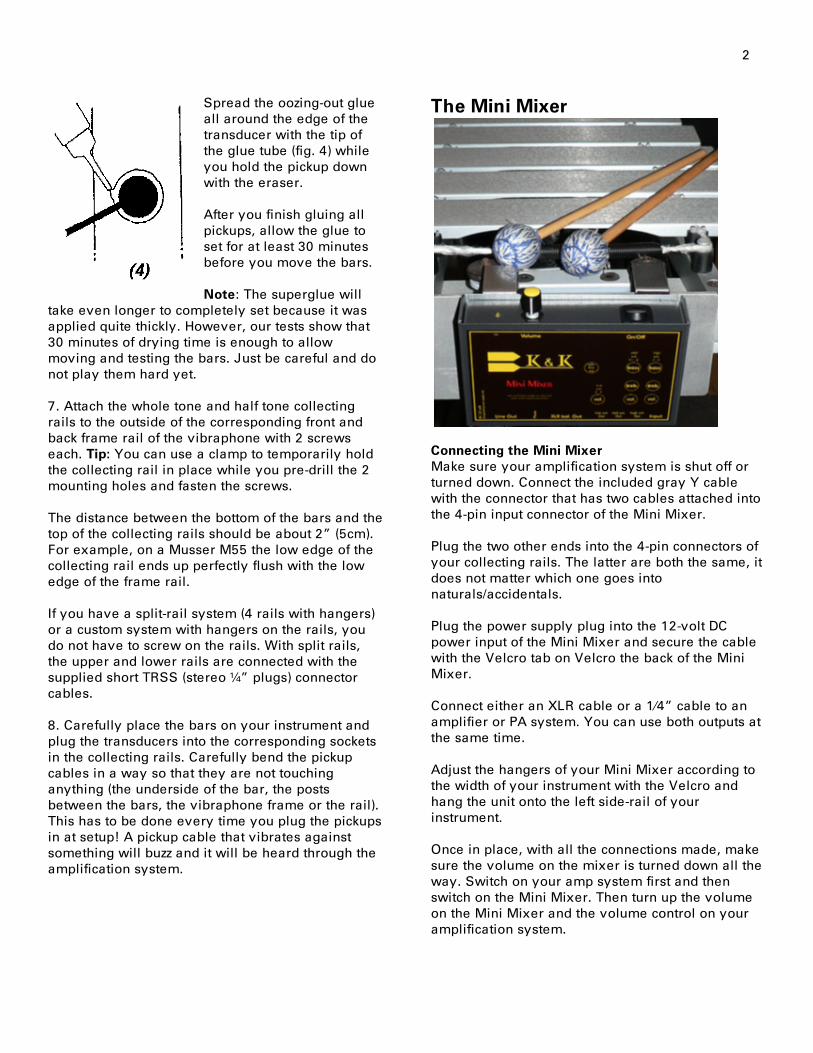
The Mini Mixer
Connecting the Mini Mixer Make sure your amplification system is shut off or turned down. Connect the included gray Y cable with the connector that has two cables attached into the 4-pin input connector of the Mini Mixer. Plug the two other ends into the 4-pin connectors of your collecting rails. The latter are both the same, it does not matter which one goes into naturals/accidentals.
Plug the power supply plug into the 12-volt DC power input of the Mini Mixer and secure the cable with the Velcro tab on Velcro the back of the Mini Mixer.
Connect either an XLR cable or a 1⁄4” cable to an amplifier or PA system. You can use both outputs at the same time.
Adjust the hangers of your Mini Mixer according to the width of your instrument with the Velcro and hang the unit onto the left side-rail of your instrument.
Once in place, with all the connections made, make sure the volume on the mixer is turned down all the way. Switch on your amp system first and then switch on the Mini Mixer. Then turn up the volume on the Mini Mixer and the volume control on your amplification system.

3
Adjusting the Mini Mixer controls The Mini Mixer functions like a 3-channel mixing board. Inside the unit there are trimpots for volume and EQ controls for each of the 3 channels individually. They have been factory-pre-set, but you can adjust them with a precision screwdriver any time you like.
The low octave range on a standard 3-octave vibe (F-F) has a volume control only. The middle range (F#-E) and high range (F-F) features specially tailored bass- and treble EQ’s. Note: These ranges will be different for marimba/ xylophone or bigger vibraphones. You’ll use bigger low- and high octave groups here. The controls inside the Mini Mixer allow you to dial in a clean and balanced sound across the entire keyboard, eliminating the unwanted mallet impact noise (“thud”) in the higher registers by cutting the bass EQ and progressively adding some treble on the medium and especially the high tone bars. There is one additional trimpot for the gain adjustment of the 1⁄4” line output (line output gain, see picture below). It is factory preset to about 50%.
That means you can adjust the line output louder or softer in relation to the XLR output (PA output), depending on the specific amplifier you are using. Outputs of the Mini Mixer There are 3 output formats on your Mini Mixer: • 1 Unbalanced 1⁄4” line output. • 1 Balanced XLR output. • 3 Unbalanced 1/8” outputs, one for each octave
range Naturally you may use the 1⁄4” output when you connect to a 1⁄4” input on your amplifier or effect unit. The balanced XLR output will allow you to use very long cables (100+ feet) without signal loss. Plus it is the preferred format on PA systems. The 3 individual octave outputs require special adapter cables (1/8” plug to ¼” plug , not supplied) and are great for studio work. For example, you can panorama the keyboard (low octave to left, mid octave center, high octave to right) or you can apply different effects to each octave. These outputs are post the EQ in the Mini Mixer and not effected by the main volume knob. You can use all 3 outputs options simultaneously.

4
How the Phase Switch Works Phase determines at what point in time a sound wave has its peak or trough.
This picture shows 2 (basically identical) sine- waves, but the wave on the right (2) is inverted in respect to the wave on the left (1). Interestingly, if these two waves were played back simultaneously from the same speaker-source with the same volume, they would completely cancel
each other out and no sound would be heard. There would be silence. This phenomenon is called phase- cancellation. Your vibraphone or marimba, like any acoustic instrument, acoustically projects sound waves in a certain phase when it is played unplugged. The phase that is projected from the amplified speaker source needs to be "in phase" with the acoustic instrument's own sound-waves or the result will not be optimal. Out-of-phase vibraphone sound reproduction may also suffer, to a relatively small degree but still noticeable, from phase cancellations. Amplification systems, effect units, or any electronic audio device may or may not invert the phase in of the signal coming in. The manufacturers unfortunately do not specify. This phase switch allows for instant correction of a phase cancellation problem. Gladly the vibraphone is not particularity prone to severe out of phase problems, but you will still notice a slightly fuller, warmer tone in the correct phase setting. Toggling the phase switch back and forth while playing and carefully listening, you will find that in one direction the sound is richer than in the other. Keep in mind that it may be different with different amplification systems and even with different distances to your monitor speaker source.
Technical Data Input: 4 pin barrel connector, high ohmic Line Output: 1/4” – 100 Ohm unbalanced XLR Output: 100 Ohm balanced EQ: Mid octave – high pass bass @ 150hz +/-15db – low pass treble @ 7500Hz +/-15db EQ: High octave – high pass bass @ 250hz +/-15db – low pass treble @ 8500Hz +/-15db Frequency response 50 - 20000 Hz
Power Supply In order to get the best performance please use a low ripple voltage 12-volt DC, 0.5-Ampere model. The DC plug must be center plus.
Transporting Your System To securely transport your new system, please acquire two pieces of thin foam (1/4”, 6mm is fine). Place the bars pickup-side up on the foam and carefully roll them up. You can give your pickups additional protection by carefully sealing the edges around the pickup disc as described in #6 (see fig. 4) plus by reinforcing them with silicone (next section).
Reinforcing with Silicone Our vibraphone pickups are designed for maximum sound quality and best possible durability. However, the constant vibration of the note bar can cause some stress to the pickup cable’s entry point. To avoid cable breakage, we have developed this protection method. It will also protect the superglue bonding. Note: Make sure that your system has been fine-tuned (all bars balanced in volume and sound) and that the superglue has dried for at least 24 hours before starting this procedure. If done right, this method will reinforce the pickup without jeopardizing any tonal characteristics. All you need is a tube of 100% caulking silicone (the type you use around your bathtub). Do not use marine silicone or car-related products as they may contain metal-corrosive materials. Important: Do not use anything but 100% caulking silicone. Other materials may harden over time, which will cause problems! Color doesn't matter, however, we prefer clear. Silicone is widely available in most hardware stores in toothpaste-sized tubes. • Place the bars on a table with pickups facing up. • Clean the area around the pickup with rubbing
alcohol and let dry. • Prepare you silicone tube and tip.

5
• Apply silicone as shown in fig. 1 (below).
• Reinforce the point where the cable connects to
the pickup disc. Make sure that you fully cover at least ¼” (6mm) of the cable near the pickup disc. This flexible cable entry point tends to absorb the most vibrations.
• Cover the lower half of the pickup disk with
silicone as well. • The silicone should be applied about 1/8” (3-4
mm) high. • Don’t worry if the silicone surface is not smooth
or if the coatings vary slightly in size or height. The silicone will generally not affect the sound quality or decay of your instrument because it stays soft and does not harden.
• However, make sure that you do not use too
much silicone on your high octave bars. They are smaller in size and thus the silicone spot appears “bigger” in relation to the bar size.
• Let dry for at least 12 hours.
Troubleshooting If ONE tone does not work, replace the pickup: Cut transducer disk off the note bar with a sharp, thin-bladed knife or with a razor blade. Remove glue residue from tone-bar with sandpaper and clean the area with rubbing alcohol. Wipe dry. Attach new pickup according to mounting instructions.
One octave does not work: Unplug all transducers within the corresponding octave range. (F - F, F# - E, F - F). Make sure to unplug ALL whole notes – plus - ALL half notes before starting the test.
Plug each transducer in separately. Test each tone one by one. If it works, unplug the transducer and go on to the next one. Continue this procedure through all the unplugged pickups. Like this, you will be able to identify the bad transducer(s). One defective transducer can cause the entire octave to cut out. Exchange bad pickup(s). (See above) If the octave still does not respond, there might be a problem with the Mini Mixer or with the connection cable. In this case, please contact K & K for further assistance. Uneven volume of single notes: Check the trim-pot setting at the individual trimmers in the collecting rails. Adjust to your liking. Note: The fully counterclockwise setting is not zero volume. It is a reduction of the signal by about 30%. If one tone changes its volume after having worked fine before, it may be due to a weak gluing or a bad pickup. Try to carefully remove the transducer. If it isn’t damaged, reattach it and test. If it is bent or otherwise blemished, replace it (see above). Distorted audio sound: The vibraphone provides extremely high-level signal amplitudes. The initial attack loudness sustains for a long time without decreasing considerably. This is a unique phenomenon caused by the properties of the vibraphone bars. This occurrence might overload electronic components used in the amplification equipment. The problem usually occurs if the musician plays many notes at once (4 mallets) at high volumes or with heavy mallets. There are several remedies: • Turn down the volume trimmers of each
individual octave inside the Mini Mixer. • Turn down the trim pots on the collecting rails. • Use lighter mallets. • Use a compressor limiter to limit the peak
amplitude of the output signal. These units are available in your music store for $100-200.
• Make sure not to peak amplification components, such as effect units, preamps and mixing consoles.

6
• Power amplifiers should have sufficient wattage to carry the immense workload.
• Speaker cabinets: Pay special attention to the horns and tweeters. In a speaker cabinet, the high tone systems tend to distort first. Make sure to use units of good quality, strong enough and capable of tolerating the extreme amplitudes of the vibraphone bar. If possible use speaker cabinets without tweeters.
How to locate the unit in your signal chain that is causing distortion: • Record your vibe audio directly out of the Mini
Mixer into a quality recording device. • Adjust record level clearly below peak. • Record a short test tune. • Listen and check for distortion at normal volume
level. • Add your effect units or mixer devices one at a
time. • Identify the source of distortion from the
recording. • If none of the devices cause the distortion, try
different power amp or speaker cabinets for identification.
• If the above steps do not render results, distortion might be caused by K & K equipment. Please contact us for further assistance.
Buzzing sound of single notes: The short transducer cable may be in contact with the bar, frame, rubber-ring of post or with the collecting rail. Make sure to bend the cable in a way so that it is not touching anything. If the problem persists, the pickup might have been attached incorrectly. Try to carefully remove the transducer. If it isn’t damaged you may reinstall it and test it. If it is bent or otherwise blemished, replace it (see above). If you are experiencing problems with significant drop in volume, excessive distortion, or if the system completely fails to work: Check the DC wall adapter power supply with a voltmeter to measure the output voltage. It should read 12 –15 volt. If you do not have a volt meter try a different wall adapter with these specifications: • Output voltage: 12-volt DC, 0.5 Ampere • Polarity of the plug: Center plus • If the above steps do not render results, other
equipment might be causing distortion. Please contact us for further assistance.