VHF TRANSCEIVER i2200H - ICOM Canadaicomcanada.com/products/amateur/ic-2200h/Amateur_IC-2200H... ·...
108
INSTRUCTION MANUAL i2200H VHF TRANSCEIVER This device complies with Part 15 of the FCC rules. Operation is sub- ject to the following two conditions: (1) This device may not cause harmful interference, and (2) this device must accept any interference received, including interference that may cause undesired operation.
Transcript of VHF TRANSCEIVER i2200H - ICOM Canadaicomcanada.com/products/amateur/ic-2200h/Amateur_IC-2200H... ·...
INSTRUCTION MANUAL
i2200HVHF TRANSCEIVER
This device complies with Part 15 of the FCC rules. Operation is sub-ject to the following two conditions: (1) This device may not causeharmful interference, and (2) this device must accept any interferencereceived, including interference that may cause undesired operation.

i
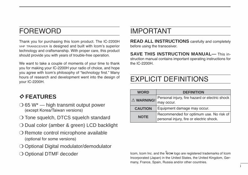
FOREWORDThank you for purchasing this Icom product. The IC-2200HVHF TRANSCEIVER is designed and built with Icom’s superiortechnology and craftsmanship. With proper care, this productshould provide you with years of trouble-free operation.
We want to take a couple of moments of your time to thankyou for making your IC-2200H your radio of choice, and hopeyou agree with Icom’s philosophy of “technology first.” Manyhours of research and development went into the design ofyour IC-2200H.
DD FEATURES 65 W* — high transmit output power
(except Korea/Taiwan versions)
Tone squelch, DTCS squelch standard
Dual color (amber & green) LCD backlight
Remote control microphone available(optional for some versions)
Optional Digital modulator/demodulator
Optional DTMF decoder
IMPORTANTREAD ALL INSTRUCTIONS carefully and completelybefore using the transceiver.
SAVE THIS INSTRUCTION MANUAL— This in-struction manual contains important operating instructions forthe IC-2200H.
EXPLICIT DEFINITIONS
WORD DEFINITION
R WARNING!
CAUTION
NOTE
Personal injury, fire hazard or electric shockmay occur.
Equipment damage may occur.
Recommended for optimum use. No risk ofpersonal injury, fire or electric shock.
Icom, Icom Inc. and the logo are registered trademarks of IcomIncorporated (Japan) in the United States, the United Kingdom, Ger-many, France, Spain, Russia and/or other countries.

ii
RWARNING RF EXPOSURE! This device emitsRadio Frequency (RF) energy. Extreme caution should be ob-served when operating this device. If you have any questions re-garding RF exposure and safety standards please refer to theFederal Communications Commission Office of Engineering andTechnology’s report on Evaluating Compliance with FCC Guide-lines for Human Radio frequency Electromagnetic Fields (OETBulletin 65)
RWARNING! NEVER connect the transceiver to an ACoutlet. This may pose a fire hazard or result in an electric shock.
RWARNING! NEVER operate the transceiver while dri-ving a vehicle. Safe driving requires your full attention—anythingless may result in an accident.
NEVER connect the transceiver to a power source of morethan 16 V DC. This will ruin the transceiver.
NEVER connect the transceiver to a power source using re-verse polarity. This will ruin the transceiver.
NEVER cut the DC power cable between the DC plug andfuse holder. If an incorrect connection is made after cutting, thetransceiver may be damaged.
NEVER expose the transceiver to rain, snow or any liquids.The transceiver may be damaged.
NEVER operate or touch the transceiver with wet hands. Thismay result in an electric shock or ruin the transceiver.
NEVER place the transceiver where normal operation of thevehicle may be hindered or where it could cause bodily injury.
DO NOT push the PTT when not actually desiring to transmit.
DO NOT allow children to play with any radio equipment con-taining a transmitter.
During mobile operation, DO NOT operate the transceiverwithout running the vehicle’s engine. When the transceiver’spower is ON and your vehicle’s engine is OFF, the vehicle’s bat-tery will soon become exhausted.
BE CAREFUL! The transceiver will become hot when op-erating it continuously for long periods.
AVOID placing the transceiver against walls or putting any-thing on the top of the transceiver. This will obstruct heat dissi-pation.
AVOID using or placing the transceiver in direct sunlight or inareas with temperatures below –10°C (+14˚F) or above +60°C(+140˚F).
AVOID the use of chemical agents such as benzine or alcoholwhen cleaning, as they can damage the transceiver’s surfaces.
USE Icom microphones only (supplied or optional). Other man-ufacturer’s microphones have different pin assignments and maydamage the transceiver if attached.
PRECAUTION
iii
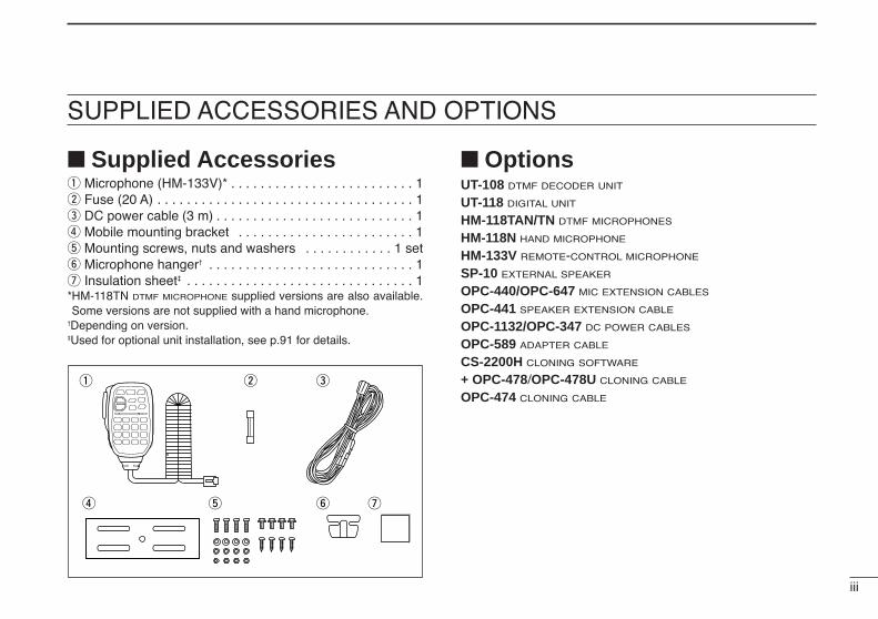
SUPPLIED ACCESSORIES AND OPTIONS
Supplied Accessoriesq Microphone (HM-133V)* . . . . . . . . . . . . . . . . . . . . . . . . . 1w Fuse (20 A) . . . . . . . . . . . . . . . . . . . . . . . . . . . . . . . . . . . 1e DC power cable (3 m) . . . . . . . . . . . . . . . . . . . . . . . . . . . 1r Mobile mounting bracket . . . . . . . . . . . . . . . . . . . . . . . . 1t Mounting screws, nuts and washers . . . . . . . . . . . . 1 sety Microphone hanger† . . . . . . . . . . . . . . . . . . . . . . . . . . . . 1u Insulation sheet‡ . . . . . . . . . . . . . . . . . . . . . . . . . . . . . . . 1*HM-118TN DTMF MICROPHONE supplied versions are also available.Some versions are not supplied with a hand microphone.
†Depending on version.‡Used for optional unit installation, see p.91 for details.
OptionsUT-108 DTMF DECODER UNIT
UT-118 DIGITAL UNIT
HM-118TAN/TN DTMF MICROPHONES
HM-118N HAND MICROPHONE
HM-133V REMOTE-CONTROL MICROPHONE
SP-10 EXTERNAL SPEAKER
OPC-440/OPC-647 MIC EXTENSION CABLES
OPC-441 SPEAKER EXTENSION CABLE
OPC-1132/OPC-347 DC POWER CABLES
OPC-589 ADAPTER CABLE
CS-2200H CLONING SOFTWARE
+ OPC-478/OPC-478U CLONING CABLE
OPC-474 CLONING CABLE
q w e
r t y u

iv
TABLE OF CONTENTS
FOREWORD ........................................................................................... iIMPORTANT ............................................................................................ iEXPLICIT DEFINITIONS ......................................................................... iPRECAUTION ........................................................................................ iiSUPPLIED ACCESSORIES AND OPTIONS ......................................... iiiTABLE OF CONTENTS ......................................................................... ivQUICK REFERENCE GUIDE ............................................................ I–VI
Installation ....................................................................................... I Your first contact ........................................................................... IV Repeater operation ........................................................................ V Programming memory .................................................................. VI
1 PANEL DESCRIPTION ................................................................. 1–8 Front panel ..................................................................................... 1 Function display ............................................................................. 3 Rear panel ..................................................................................... 5 Microphone (HM-133V) .................................................................. 6 Microphone keypad ........................................................................ 7
2 SETTING A FREQUENCY .......................................................... 9–12 Preparation .................................................................................... 9 Using the tuning dial ...................................................................... 9 Using the keypad ......................................................................... 10 Using the [Y]/[Z] keys ................................................................. 10 Tuning step selection ................................................................... 11 Lock functions .............................................................................. 12
3 BASIC OPERATION ................................................................. 13–16 Receiving ..................................................................................... 13 Monitor function ........................................................................... 13 Audio mute function ..................................................................... 14 Squelch attenuator ....................................................................... 14 S-meter squelch ........................................................................... 15
Transmitting ................................................................................. 15 Selecting output power ................................................................ 16 One-touch PTT function ............................................................... 16
4 REPEATER OPERATION ......................................................... 17–23 Accessing a repeater ................................................................... 17 Subaudible tones ......................................................................... 19 Offset frequency .......................................................................... 21 Repeater lockout .......................................................................... 21 Reversed duplex mode ................................................................ 22 Auto repeater ............................................................................... 23
5 MEMORY OPERATION ............................................................ 24–34 General description ...................................................................... 24 Memory channel selection ........................................................... 24 Programming a memory channel ................................................. 25 Transferring memory contents ..................................................... 27 Programming channel names....................................................... 29 Memory clearing .......................................................................... 31 Memory bank selection ................................................................ 32 Memory bank setting .................................................................... 33 Transferring bank contents .......................................................... 34
6 CALL CHANNEL OPERATION ................................................ 35–36 Call channel selection .................................................................. 35 Call channel transferring .............................................................. 35 Programming a call channel ........................................................ 36
7 SCAN OPERATION .................................................................. 37–42 Scan types ................................................................................... 37 Scan start/stop ............................................................................. 38 Scan edges programming ............................................................ 39 Skip channel setting ..................................................................... 41 Scan resume condition ................................................................ 42

v
8 PRIORITY WATCH .................................................................... 43–44 Priority watch types ...................................................................... 43 Priority watch operation ............................................................... 44
9 DTMF MEMORY ENCODER ..................................................... 45–47 Programming a DTMF code ......................................................... 45 Transmitting a DTMF code .......................................................... 46 DTMF speed ................................................................................ 47
10 POCKET BEEP AND TONE SQUELCH ................................... 48–51 Pocket beep operation ................................................................. 48 Tone/DTCS squelch operation ..................................................... 50 Tone scan ..................................................................................... 51
11 PAGER/CODE SQUELCH (Required Optional UT-108).......... 52–57 Pager function .............................................................................. 52 Code programming ...................................................................... 52 Pager operation ........................................................................... 55 Code squelch ............................................................................... 57
12 DIGITAL MODE OPERATION (Required Optional UT-118) .... 58–73 Digital mode operation ................................................................. 58 Call sign programming ................................................................. 58 Digital voice mode operation ........................................................ 61 When receiving a Digital call ........................................................ 63 Break-in communication .............................................................. 65 EMG communication .................................................................... 66 Digital code/Call sign squelch operation ...................................... 67 Slow data communication ............................................................ 68 Other setting items ....................................................................... 69 GPS operation ............................................................................. 72
13 OTHER FUNCTIONS ................................................................ 74–87 Set mode ...................................................................................... 74 Initial set mode ............................................................................. 79
Weather channel operation .......................................................... 83 Microphone keys .......................................................................... 84 Partial reset .................................................................................. 85 All reset ........................................................................................ 85 Data cloning ................................................................................. 86
14 SPECIFICATIONS ........................................................................... 8815 MAINTENANCE ........................................................................ 89–91
Troubleshooting ........................................................................... 89 Fuse replacement ........................................................................ 90 Optional unit installation ............................................................... 91
16 CE .................................................................................................... 9217 MODE ARRANGEMENT ........................................................... 93–94
1234567891011121314151617
I
QUICK REFERENCE GUIDE
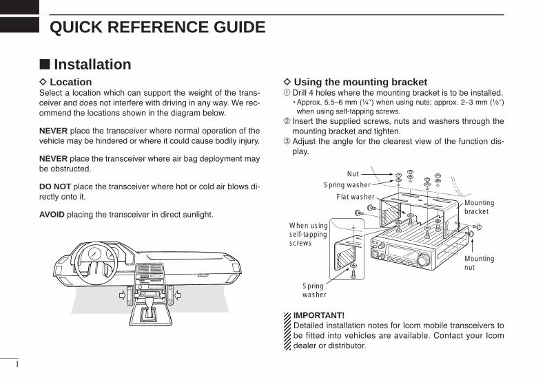
InstallationD LocationSelect a location which can support the weight of the trans-ceiver and does not interfere with driving in any way. We rec-ommend the locations shown in the diagram below.
NEVER place the transceiver where normal operation of thevehicle may be hindered or where it could cause bodily injury.
NEVER place the transceiver where air bag deployment maybe obstructed.
DO NOT place the transceiver where hot or cold air blows di-rectly onto it.
AVOID placing the transceiver in direct sunlight.
D Using the mounting bracket➀ Drill 4 holes where the mounting bracket is to be installed.
• Approx. 5.5–6 mm (1⁄4″) when using nuts; approx. 2–3 mm (1⁄8″)when using self-tapping screws.
➁ Insert the supplied screws, nuts and washers through themounting bracket and tighten.
➂ Adjust the angle for the clearest view of the function dis-play.
IMPORTANT!Detailed installation notes for Icom mobile transceivers tobe fitted into vehicles are available. Contact your Icomdealer or distributor.
Nut
Spring washer
Flat washer
When usingself-tappingscrews
Springwasher
Mountingnut
Mountingbracket
II
QUICK REFERENCE GUIDE
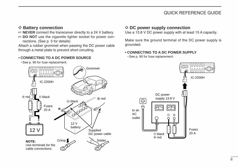
D Battery connection NEVER connect the transceiver directly to a 24 V battery. DO NOT use the cigarette lighter socket for power con-
nections. (See p. 5 for details)Attach a rubber grommet when passing the DC power cablethrough a metal plate to prevent short circuiting.
• CONNECTING TO A DC POWER SOURCE• See p. 90 for fuse replacement.
D DC power supply connectionUse a 13.8 V DC power supply with at least 15 A capacity.
Make sure the ground terminal of the DC power supply isgrounded.
• CONNECTING TO A DC POWER SUPPLY• See p. 90 for fuse replacement.
DC powersupply 13.8 V
to anACoutlet
Fuses20 Ablack
red⊕−
⊕−
IC-2200H
Fuses20 A
Crimp Solder
blackred⊕
Grommet
IC-2200H
−
12 V12 Vbattery
SuppliedDC power cable
NOTE: Use terminals for the cable connections.
+ red_ black
III
QUICK REFERENCE GUIDE
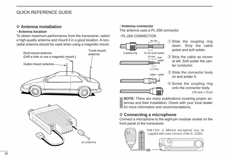
D Antenna installation• Antenna locationTo obtain maximum performance from the transceiver, selecta high-quality antenna and mount it in a good location. A non-radial antenna should be used when using a magnetic mount.
• Antenna connectorThe antenna uses a PL-259 connector.
• PL-259 CONNECTOR
q Slide the coupling ringdown. Strip the cablejacket and soft solder.
w Strip the cable as shownat left. Soft solder the cen-ter conductor.
e Slide the connector bodyon and solder it.
r Screw the coupling ringonto the connector body.
(10 mm ≈ 3⁄8 in)
NOTE: There are many publications covering proper an-tennas and their installation. Check with your local dealerfor more information and recommendations.
D Connecting a microphoneConnect a microphone to the eight-pin modular socket on thefront panel of the transceiver.
*HM-133V; A different microphone may be supplied with some versions of the IC-2200H.
30 mm
10 mm (soft solder)
10 mm
1–2 mm
solder solder
Softsolder
Coupling ring
to antenna
Roof-mount antenna(Drill a hole or use a magnetic mount.)
Gutter-mount antenna
Trunk-mountantenna

IV
QUICK REFERENCE GUIDE
Your first contactNow that you have your IC-2200H installed in your car orshack, you are probably excited to get on the air. We wouldlike to take you through a few basic operation steps to makeyour first “On The Air” an enjoyable experience.
1. Turning ON the transceiverBefore powering up your IC-2200H, you may want to makesure the audio volume and squelch level controls are set in9–10 o’clock positions.
Although you have purchased a brand new transceiver, somesettings may be changed from the factory defaults becauseof the QC process. Resetting the CPU is necessary to startfrom factory default.
While pushing [SET ] and [S.MW ], push[PWR] for 1 sec. to reset the CPU.
2. Tune the desired frequency[DIAL] will allow you to dial in the frequency you want to op-erate. Pages 9 and 11 will instruct you on how to set the tun-ing speed.
Using the HM-133VYou can directly enter the frequency with the HM-133V keypad.
We hope these pointers have been helpful. Now youare ready to call CQ.
LOCKSET
ANMMONI
DUPLOW
T-SCANTONE
PRIOM/CALL
SCANV/MHz
DIGITAL PRIO AO BUSYMUTENARMIDLOW
LOCKSET
ANMMONI
DUPLOW
T-SCANTONE
PRIOM/CALL
SCANV/MHz
DIGITAL PRIO AO BUSYMUTENARMIDLOW
LOCKSET
ANMMONI
DUPLOW
T-SCANTONE
PRIOM/CALL
SCANV/MHz
DIGITAL PRIO AO BUSYMUTENARMIDLOW
LOCKSET
ANMMONI
DUPLOW
T-SCANTONE
PRIOM/CALL
SCANV/MHz
DIGITAL PRIO AO BUSYMUTENARMIDLOW
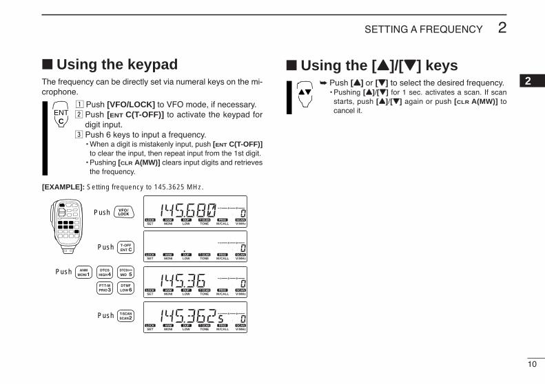
[EXAMPLE]: Setting frequency to 145.3625 MHz.
Push
Push
Push
Push
[DIAL]
MWLOCK
[PWR]
[SET LOCK][S.MW MW]
Set both [VOL] and [SQL] controls to 9–10 o’clock positions.
[VOL]
[SQL]
V
QUICK REFERENCE GUIDE
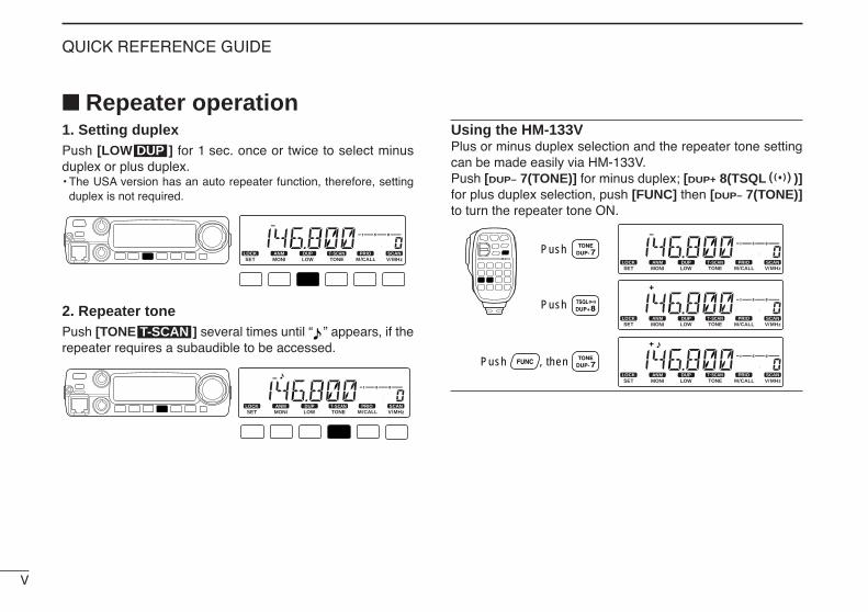
Repeater operation1. Setting duplex Push [LOW ] for 1 sec. once or twice to select minusduplex or plus duplex.• The USA version has an auto repeater function, therefore, setting
duplex is not required.
2. Repeater tone Push [TONE ] several times until “ ” appears, if therepeater requires a subaudible to be accessed.
Using the HM-133VPlus or minus duplex selection and the repeater tone settingcan be made easily via HM-133V.Push [DUP– 7(TONE)] for minus duplex; [DUP+ 8(TSQLSS)]for plus duplex selection, push [FUNC] then [DUP– 7(TONE)]to turn the repeater tone ON.
LOCKSET
ANMMONI
DUPLOW
T-SCANTONE
PRIOM/CALL
SCANV/MHz
DIGITAL PRIO AO BUSYMUTENARMIDLOW
LOCKSET
ANMMONI
DUPLOW
T-SCANTONE
PRIOM/CALL
SCANV/MHz
DIGITAL PRIO AO BUSYMUTENARMIDLOW
LOCKSET
ANMMONI
DUPLOW
T-SCANTONE
PRIOM/CALL
SCANV/MHz
DIGITAL PRIO AO BUSYMUTENARMIDLOW
Push
Push , then
Push
LOCKSET
ANMMONI
DUPLOW
T-SCANTONE
PRIOM/CALL
SCANV/MHz
DIGITAL PRIO AO BUSYMUTENARMIDLOW
T-SCAN
LOCKSET
ANMMONI
DUPLOW
T-SCANTONE
PRIOM/CALL
SCANV/MHz
DIGITAL PRIO AO BUSYMUTENARMIDLOW
DUP
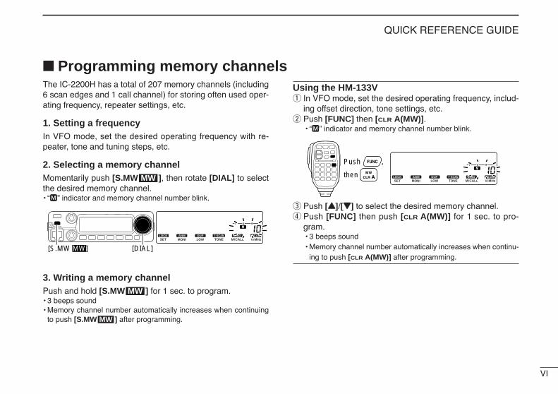
The IC-2200H has a total of 207 memory channels (including6 scan edges and 1 call channel) for storing often used oper-ating frequency, repeater settings, etc.
1. Setting a frequencyIn VFO mode, set the desired operating frequency with re-peater, tone and tuning steps, etc.
2. Selecting a memory channel Momentarily push [S.MW ], then rotate [DIAL] to selectthe desired memory channel.• “M” indicator and memory channel number blink.
3. Writing a memory channelPush and hold [S.MW ] for 1 sec. to program.• 3 beeps sound• Memory channel number automatically increases when continuing
to push [S.MW ] after programming.
Using the HM-133Vq In VFO mode, set the desired operating frequency, includ-
ing offset direction, tone settings, etc.w Push [FUNC] then [CLR A(MW)].
• “M” indicator and memory channel number blink.
e Push [YY]/[ZZ] to select the desired memory channel.r Push [FUNC] then push [CLR A(MW)] for 1 sec. to pro-
gram.• 3 beeps sound• Memory channel number automatically increases when continu-
ing to push [CLR A(MW)] after programming.
LOCKSET
ANMMONI
DUPLOW
T-SCANTONE
PRIOM/CALL
SCANV/MHz
DIGITAL PRIO AO BUSYMUTENARMIDLOW
Push ,
then
MW
MW
LOCKSET
ANMMONI
DUPLOW
T-SCANTONE
PRIOM/CALL
SCANV/MHz
DIGITAL PRIO AO BUSYMUTENARMIDLOW
[S.MW MW] [DIAL]
MW
Programming memory channels
VI
QUICK REFERENCE GUIDE
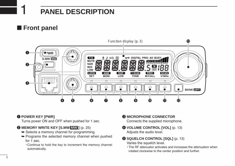
Front panel
q POWER KEY [PWR]Turns power ON and OFF when pushed for 1 sec.
w MEMORY WRITE KEY [S.MW ] (p. 25) Selects a memory channel for programming. Programs the selected memory channel when pushed
for 1 sec. • Continue to hold the key to increment the memory channel
automatically.
e MICROPHONE CONNECTORConnects the supplied microphone.
r VOLUME CONTROL [VOL] (p. 13)Adjusts the audio level.
t SQUELCH CONTROL [SQL] (p. 13)Varies the squelch level.• The RF attenuator activates and increases the attenuation when
rotated clockwise to the center position and further.
MW
PWR
S.MW MW
BANK OPT
Function display (p. 3)
!0oiuy
q
w
e
r t
!3
!1 !2
1
PANEL DESCRIPTION1
2
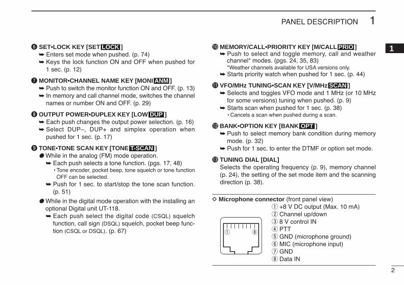
1PANEL DESCRIPTION
1y SET•LOCK KEY [SET ] Enters set mode when pushed. (p. 74) Keys the lock function ON and OFF when pushed for
1 sec. (p. 12)
u MONITOR•CHANNEL NAME KEY [MONI ] Push to switch the monitor function ON and OFF. (p. 13) In memory and call channel mode, switches the channel
names or number ON and OFF. (p. 29)
i OUTPUT POWER•DUPLEX KEY [LOW ] Each push changes the output power selection. (p. 16) Select DUP–, DUP+ and simplex operation when
pushed for 1 sec. (p. 17)
o TONE•TONE SCAN KEY [TONE ] While in the analog (FM) mode operation.
Each push selects a tone function. (pgs. 17, 48)• Tone encoder, pocket beep, tone squelch or tone function
OFF can be selected. Push for 1 sec. to start/stop the tone scan function.
(p. 51)
While in the digital mode operation with the installing anoptional Digital unit UT-118. Each push select the digital code (CSQL) squelch
function, call sign (DSQL) squelch, pocket beep func-tion (CSQL or DSQL). (p. 67)
!0 MEMORY/CALL•PRIORITY KEY [M/CALL ] Push to select and toggle memory, call and weather
channel* modes. (pgs. 24, 35, 83)*Weather channels available for USA versions only.
Starts priority watch when pushed for 1 sec. (p. 44)
!1 VFO/MHz TUNING•SCAN KEY [V/MHz ] Selects and toggles VFO mode and 1 MHz (or 10 MHz
for some versions) tuning when pushed. (p. 9) Starts scan when pushed for 1 sec. (p. 38)
• Cancels a scan when pushed during a scan.
!2 BANK•OPTION KEY [BANK ] Push to select memory bank condition during memory
mode. (p. 32) Push for 1 sec. to enter the DTMF or option set mode.
!3 TUNING DIAL [DIAL]Selects the operating frequency (p. 9), memory channel(p. 24), the setting of the set mode item and the scanningdirection (p. 38).
D Microphone connector (front panel view)q +8 V DC output (Max. 10 mA)w Channel up/downe 8 V control INr PTTt GND (microphone ground)y MIC (microphone input)u GNDi Data IN
q i
OPT
SCAN
PRIO
T-SCAN
DUP
ANM
LOCK

3
1 PANEL DESCRIPTION
Function display
qFREQUENCY READOUTShows the operating frequency, channel names, set modecontents, etc.• Frequency decimal point flashes while scanning. (p. 38)• “d” appears in place of the 1st digit while the DTMF memory
function is in use. (p. 45)
wTRANSMIT INDICATOR Appears while transmitting. (p. 15) Flashes while transmitting with the one-touch PTT func-
tion. (p. 16)
eAUDIO MUTE INDICATOR (p. 14)Appears when the audio mute function is activated via mi-crophone control.
rNARROW MODE INDICATOR (p. 78)Appears when the narrow mode is selected.Narrow mode is not available with some versions.
tOUTPUT POWER INDICATORS (p. 16)“LOW” appears when low output power; “MID” and “LOW”appear when mid low output power; “MID” appears whenmiddle output power is selected.• Mid. low power is not available with some versions.
LOCKSET
ANMMONI
DUPLOW
T-SCANTONE
PRIOM/CALL
SCANV/MHz
DIGITAL PRIO AO BUSYMUTENARMIDLOW
!7 !3!4
i
!5!6
!0
!2 !1
u
o
w
y
t
e
r
q
4
1PANEL DESCRIPTION
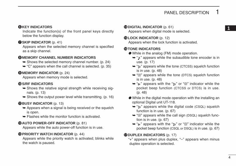
1yKEY INDICATORSIndicate the function(s) of the front panel keys directlybelow the function display.
uSKIP INDICATOR (p. 41)Appears when the selected memory channel is specifiedas a skip channel.
iMEMORY CHANNEL NUMBER INDICATORS Shows the selected memory channel number. (p. 24) “C” appears when the call channel is selected. (p. 35)
oMEMORY INDICATOR (p. 24)Appears when memory mode is selected.
!0S/RF INDICATORS Shows the relative signal strength while receiving sig-
nals. (p. 13) Shows the output power level while transmitting. (p. 16)
!1BUSY INDICATOR (p. 13) Appears when a signal is being received or the squelch
is open. Flashes while the monitor function is activated.
!2AUTO POWER-OFF INDICATOR (p. 81)Appears while the auto power-off function is in use.
!3PRIORITY WATCH INDICATOR (p. 44)Appears while the priority watch is activated; blinks whilethe watch is paused.
!4DIGITAL INDICATOR (p. 61)Appears when digital mode is selected.
!5LOCK INDICATOR (p. 12)Appears when the lock function is activated.
!6TONE INDICATORS While in the analog (FM) mode operation.
“ ” appears while the subaudible tone encoder is inuse. (p. 17)
“ ” appears while the tone (CTCSS) squelch functionis in use. (p. 48)
“ ” appears while the tone (DTCS) squelch functionis in use. (p. 48)
“ ” appears with the “ ” or “ ” indicator while thepocket beep function (CTCSS or DTCS) is in use.(p. 48)
While in the digital mode operation with the installing anoptional Digital unit UT-118. “ ” appears while the digital code (CSQL) squelch
function is in use. (p. 67) “ ” appears while the call sign (DSQL) squelch func-
tion is in use. (p. 67) “ ” appears with the “ ” or “ ” indicator while the
pocket beep function (CSQL or DSQL) is in use. (p. 67)
!7DUPLEX INDICATORS (p. 17)“+” appears when plus duplex, “–” appears when minusduplex operation is selected.

5
1 PANEL DESCRIPTION
Rear panel
q SPEAKER JACK [SP]Accepts an 8 Ω speaker.• Audio output power is more than 2.4 W.
w DATA JACK [DATA]Connects to a PC or GPS receiver via an RS-232C cable(D-sub 9-pin) for data communication in the RS-232C for-mat.
e POWER RECEPTACLE [DC13.8V]Accepts 13.8 V DC ±15% with the supplied DC powercable.
NOTE: DO NOT use a cigarette lighter socket as apower source when operating in a vehicle. The plugmay cause voltage drops and ignition noise may be su-perimposed onto transmit or receive audio.
r ANTENNA CONNECTOR [ANT]Connects a 50 Ω antenna with a PL-259 connector and a50 Ω coaxial cable.
Pin 2 (RxD), Pin 3 (TxD), Pin 5 (GND)
to [DATA] jackTxD
2.5(d) mm
GND
RxD
15
69
RS-232C (DB-9 female)
re
q
w
When making the connection between your transceiver andPC or other device, ensure that the correct connections aremade otherwise data communications may fail.
6
1PANEL DESCRIPTION
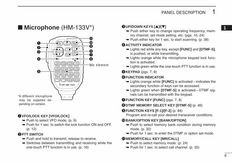
1 Microphone (HM-133V*)
qVFO/LOCK KEY [VFO/LOCK] Push to select VFO mode. (p. 9) Push for 1 sec. to switch the lock function ON and OFF.
(p. 12)
wPTT SWITCH Push and hold to transmit; release to receive. Switches between transmitting and receiving while the
one-touch PTT function is in use. (p. 16)
eUP/DOWN KEYS [Y]/[Z] Push either key to change operating frequency, mem-
ory channel, set mode setting, etc. (pgs. 10, 24) Push either key for 1 sec. to start scanning. (p. 38)
rACTIVITY INDICATOR Lights red while any key, except [FUNC] and [DTMF-S],
is pushed, or while transmitting. Lights orange while the microphone keypad lock func-
tion is activated. Lights green while the one-touch PTT function is in use.
tKEYPAD (pgs. 7, 8)
yFUNCTION INDICATOR Lights orange while [FUNC] is activated—indicates the
secondary function of keys can be accessed. Lights green when [DTMF-S] is activated—DTMF sig-
nals can be transmitted with the keypad.
uFUNCTION KEY [FUNC] (pgs. 7, 8)
iDTMF MEMORY SELECT KEY [DTMF-S] (p. 46)
oFUNCTION KEYS [F-1]/[F-2] (p. 84)Program and re-call your desired transceiver conditions.
!0BANK/OPTION KEY [BANK/OPTION] Push to select memory bank condition during memory
mode. (p. 32) Push for 1 sec. to enter the DTMF or option set mode.
!1MEMORY/CALL KEY [MR/CALL] Push to select memory mode. (p. 24) Push for 1 sec. to select call channel. (p. 35)
q
e
r
t
Mic element
yui
o!0!1
w
*A different microphonemay be supplied de-pending on version.
7
1 PANEL DESCRIPTION
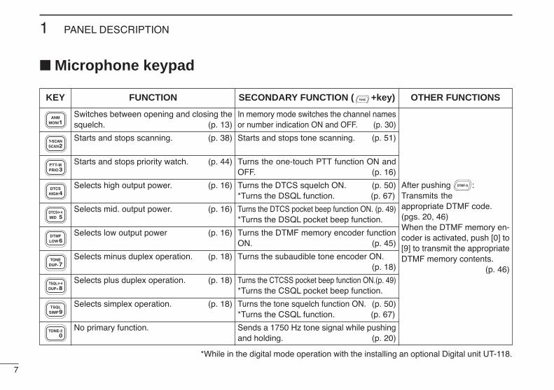
Microphone keypad
KEY FUNCTION SECONDARY FUNCTION ( +key) OTHER FUNCTIONS
Switches between opening and closing thesquelch. (p. 13)
Starts and stops scanning. (p. 38)
Starts and stops priority watch. (p. 44)
Selects high output power. (p. 16)
Selects mid. output power. (p. 16)
Selects low output power (p. 16)
Selects minus duplex operation. (p. 18)
Selects plus duplex operation. (p. 18)
Selects simplex operation. (p. 18)
No primary function.
In memory mode switches the channel namesor number indication ON and OFF. (p. 30)
Starts and stops tone scanning. (p. 51)
Turns the one-touch PTT function ON andOFF. (p. 16)
Turns the DTCS squelch ON. (p. 50)*Turns the DSQL function. (p. 67)
Turns the DTCS pocket beep function ON. (p. 49)*Turns the DSQL pocket beep function.
Turns the DTMF memory encoder functionON. (p. 45)
Turns the subaudible tone encoder ON.(p. 18)
Turns the CTCSS pocket beep function ON.(p. 49)*Turns the CSQL pocket beep function.
Turns the tone squelch function ON. (p. 50)*Turns the CSQL function. (p. 67)
Sends a 1750 Hz tone signal while pushingand holding. (p. 20)
After pushing :Transmits theappropriate DTMF code.(pgs. 20, 46)When the DTMF memory en-coder is activated, push [0] to[9] to transmit the appropriateDTMF memory contents.
(p. 46)
*While in the digital mode operation with the installing an optional Digital unit UT-118.
8
1PANEL DESCRIPTION
1
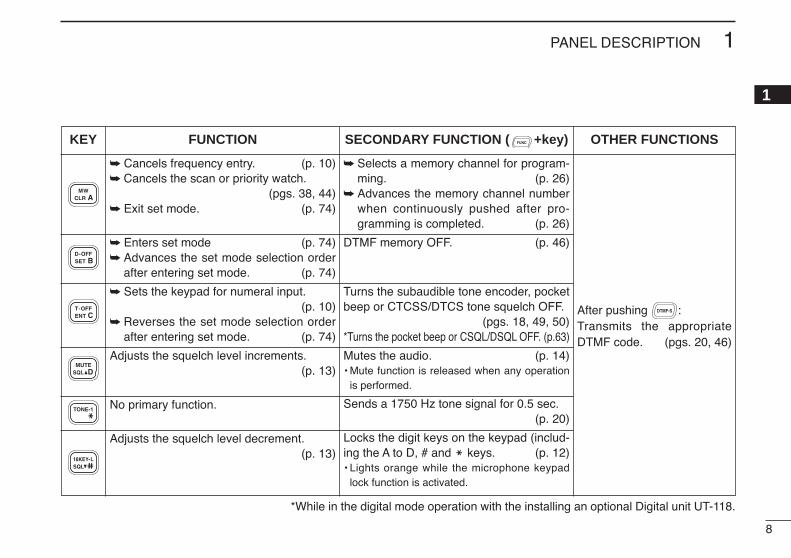
Cancels frequency entry. (p. 10) Cancels the scan or priority watch.
(pgs. 38, 44) Exit set mode. (p. 74)
Enters set mode (p. 74) Advances the set mode selection order
after entering set mode. (p. 74)
Sets the keypad for numeral input.(p. 10)
Reverses the set mode selection orderafter entering set mode. (p. 74)
Adjusts the squelch level increments.(p. 13)
No primary function.
Adjusts the squelch level decrement. (p. 13)
Selects a memory channel for program-ming. (p. 26)
Advances the memory channel numberwhen continuously pushed after pro-gramming is completed. (p. 26)
DTMF memory OFF. (p. 46)
Turns the subaudible tone encoder, pocketbeep or CTCSS/DTCS tone squelch OFF.
(pgs. 18, 49, 50)*Turns the pocket beep or CSQL/DSQL OFF. (p.63)
Mutes the audio. (p. 14)• Mute function is released when any operation
is performed.
Sends a 1750 Hz tone signal for 0.5 sec.(p. 20)
Locks the digit keys on the keypad (includ-ing the A to D, # and M keys. (p. 12)• Lights orange while the microphone keypad
lock function is activated.
After pushing :Transmits the appropriateDTMF code. (pgs. 20, 46)
KEY FUNCTION SECONDARY FUNCTION ( +key) OTHER FUNCTIONS
*While in the digital mode operation with the installing an optional Digital unit UT-118.
9
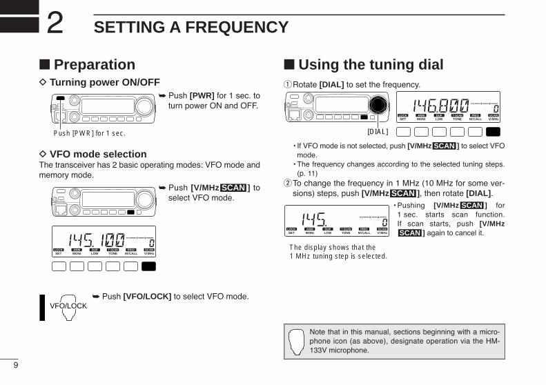
SETTING A FREQUENCY2 PreparationD Turning power ON/OFF
Push [PWR] for 1 sec. toturn power ON and OFF.
D VFO mode selectionThe transceiver has 2 basic operating modes: VFO mode andmemory mode.
Push [V/MHz ] toselect VFO mode.
Push [VFO/LOCK] to select VFO mode.
Using the tuning dialqRotate [DIAL] to set the frequency.
• If VFO mode is not selected, push [V/MHz ] to select VFOmode.
• The frequency changes according to the selected tuning steps.(p. 11)
wTo change the frequency in 1 MHz (10 MHz for some ver-sions) steps, push [V/MHz ], then rotate [DIAL].
• Pushing [V/MHz ] for1 sec. starts scan function. If scan starts, push [V/MHz
] again to cancel it.SCAN
SCAN
LOCKSET
ANMMONI
DUPLOW
T-SCANTONE
PRIOM/CALL
SCANV/MHz
DIGITAL PRIO AO BUSYMUTENARMIDLOW
The display shows that the 1 MHz tuning step is selected.
SCAN
SCAN
LOCKSET
ANMMONI
DUPLOW
T-SCANTONE
PRIOM/CALL
SCANV/MHz
DIGITAL PRIO AO BUSYMUTENARMIDLOW
[DIAL]
VFO/LOCK
SCAN
LOCKSET
ANMMONI
DUPLOW
T-SCANTONE
PRIOM/CALL
SCANV/MHz
DIGITAL PRIO AO BUSYMUTENARMIDLOW
Push [PWR] for 1 sec.
Note that in this manual, sections beginning with a micro-phone icon (as above), designate operation via the HM-133V microphone.
10
2SETTING A FREQUENCY
2 Using the keypadThe frequency can be directly set via numeral keys on the mi-crophone.
z Push [VFO/LOCK] to VFO mode, if necessary.x Push [ENT C(T-OFF)] to activate the keypad for
digit input.c Push 6 keys to input a frequency.
• When a digit is mistakenly input, push [ENT C(T-OFF)]to clear the input, then repeat input from the 1st digit.
• Pushing [CLR A(MW)] clears input digits and retrievesthe frequency.
Using the [Y]/[Z] keys Push [YY] or [ZZ] to select the desired frequency.
• Pushing [YY]/[ZZ] for 1 sec. activates a scan. If scanstarts, push [YY]/[ZZ] again or push [CLR A(MW)] tocancel it.
YZ
LOCKSET
ANMMONI
DUPLOW
T-SCANTONE
PRIOM/CALL
SCANV/MHz
DIGITAL PRIO AO BUSYMUTENARMIDLOW
LOCKSET
ANMMONI
DUPLOW
T-SCANTONE
PRIOM/CALL
SCANV/MHz
DIGITAL PRIO AO BUSYMUTENARMIDLOW
LOCKSET
ANMMONI
DUPLOW
T-SCANTONE
PRIOM/CALL
SCANV/MHz
DIGITAL PRIO AO BUSYMUTENARMIDLOW
LOCKSET
ANMMONI
DUPLOW
T-SCANTONE
PRIOM/CALL
SCANV/MHz
DIGITAL PRIO AO BUSYMUTENARMIDLOW
[EXAMPLE]: Setting frequency to 145.3625 MHz.
Push
Push
Push
Push
ENTC
11
2 SETTING A FREQUENCY
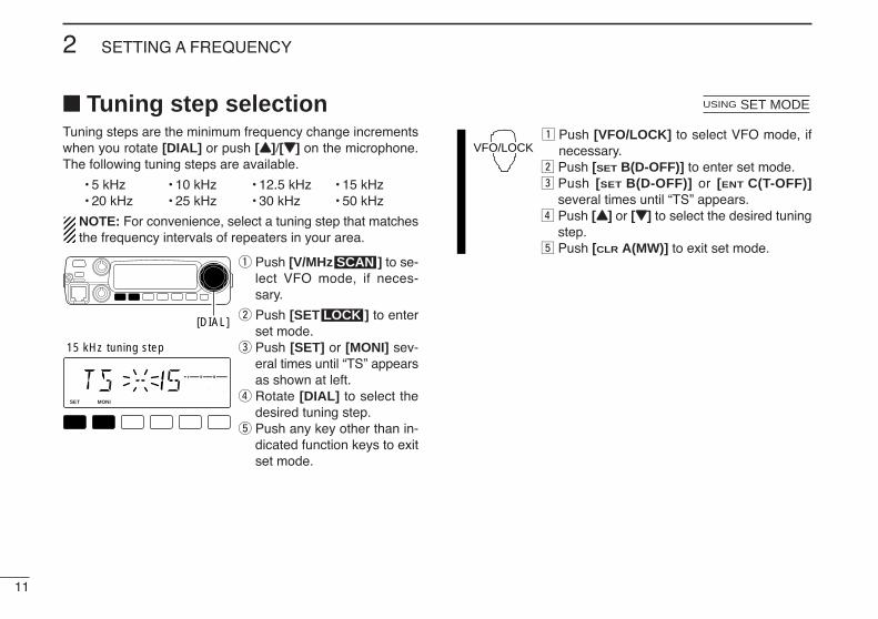
Tuning step selectionTuning steps are the minimum frequency change incrementswhen you rotate [DIAL] or push [YY]/[ZZ] on the microphone.The following tuning steps are available.
• 5 kHz • 10 kHz • 12.5 kHz • 15 kHz• 20 kHz • 25 kHz • 30 kHz • 50 kHz
NOTE: For convenience, select a tuning step that matchesthe frequency intervals of repeaters in your area.
q Push [V/MHz ] to se-lect VFO mode, if neces-sary.
w Push [SET ] to enterset mode.
e Push [SET] or [MONI] sev-eral times until “TS” appearsas shown at left.
r Rotate [DIAL] to select thedesired tuning step.
t Push any key other than in-dicated function keys to exitset mode.
z Push [VFO/LOCK] to select VFO mode, ifnecessary.
x Push [SET B(D-OFF)] to enter set mode.c Push [SET B(D-OFF)] or [ENT C(T-OFF)]
several times until “TS” appears.v Push [YY] or [ZZ] to select the desired tuning
step.b Push [CLR A(MW)] to exit set mode.
VFO/LOCK
USING SET MODE
LOCK
SCAN
LOCKSET
ANMMONI
DUPLOW
T-SCANTONE
PRIOM/CALL
SCANV/MHz
DIGITAL PRIO AO BUSYMUTENARMIDLOW
15 kHz tuning step
[DIAL]
12
2SETTING A FREQUENCY
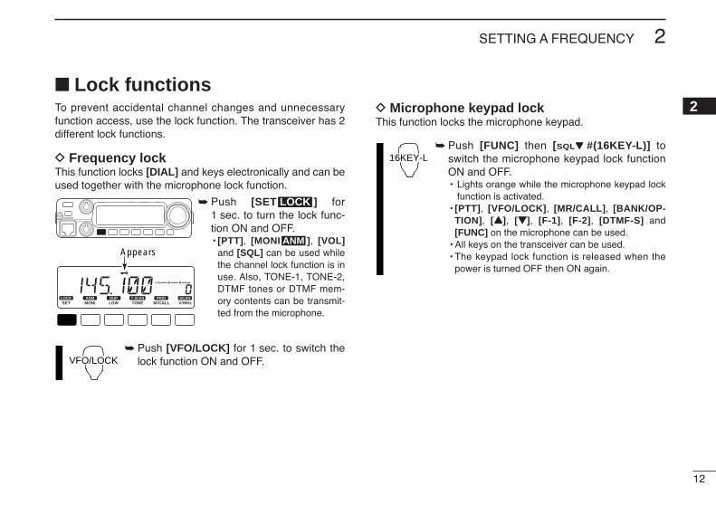
2 Lock functionsTo prevent accidental channel changes and unnecessaryfunction access, use the lock function. The transceiver has 2different lock functions.
D Frequency lockThis function locks [DIAL] and keys electronically and can beused together with the microphone lock function.
Push [SET ] for1 sec. to turn the lock func-tion ON and OFF.• [PTT], [MONI ], [VOL]
and [SQL] can be used whilethe channel lock function is inuse. Also, TONE-1, TONE-2,DTMF tones or DTMF mem-ory contents can be transmit-ted from the microphone.
Push [VFO/LOCK] for 1 sec. to switch thelock function ON and OFF.
D Microphone keypad lockThis function locks the microphone keypad.
Push [FUNC] then [SQLZZ #(16KEY-L)] toswitch the microphone keypad lock functionON and OFF.• Lights orange while the microphone keypad lock
function is activated.• [PTT], [VFO/LOCK], [MR/CALL], [BANK/OP-
TION], [YY], [ZZ], [F-1], [F-2], [DTMF-S] and[FUNC] on the microphone can be used.
• All keys on the transceiver can be used.• The keypad lock function is released when the
power is turned OFF then ON again.
16KEY-L
VFO/LOCK
ANM
LOCK
LOCKSET
ANMMONI
DUPLOW
T-SCANTONE
PRIOM/CALL
SCANV/MHz
DIGITAL PRIO AO BUSYMUTENARMIDLOW
Appears
13
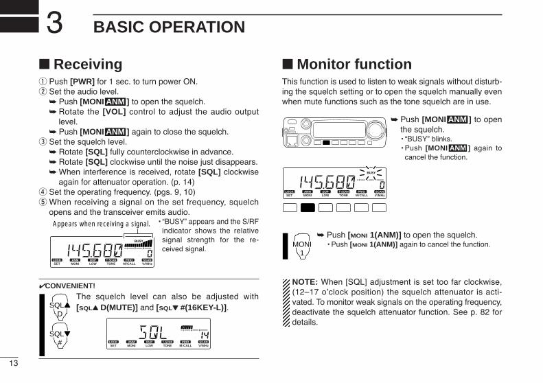
BASIC OPERATION3 Receivingq Push [PWR] for 1 sec. to turn power ON.w Set the audio level.
Push [MONI ] to open the squelch. Rotate the [VOL] control to adjust the audio output
level. Push [MONI ] again to close the squelch.
e Set the squelch level. Rotate [SQL] fully counterclockwise in advance. Rotate [SQL] clockwise until the noise just disappears. When interference is received, rotate [SQL] clockwise
again for attenuator operation. (p. 14)r Set the operating frequency. (pgs. 9, 10)t When receiving a signal on the set frequency, squelch
opens and the transceiver emits audio.• “BUSY” appears and the S/RF
indicator shows the relativesignal strength for the re-ceived signal.
CONVENIENT!
The squelch level can also be adjusted with[SQLYY D(MUTE)] and [SQLZZ #(16KEY-L)].
Monitor functionThis function is used to listen to weak signals without disturb-ing the squelch setting or to open the squelch manually evenwhen mute functions such as the tone squelch are in use.
Push [MONI ] to openthe squelch.• “BUSY” blinks.• Push [MONI ] again to
cancel the function.
Push [MONI 1(ANM)] to open the squelch.• Push [MONI 1(ANM)] again to cancel the function.
NOTE: When [SQL] adjustment is set too far clockwise,(12–17 o’clock position) the squelch attenuator is acti-vated. To monitor weak signals on the operating frequency,deactivate the squelch attenuator function. See p. 82 fordetails.
MONI1
ANM
ANM
LOCKSET
ANMMONI
DUPLOW
T-SCANTONE
PRIOM/CALL
SCANV/MHz
DIGITAL PRIO AO BUSYMUTENARMIDLOW
LOCKSET
ANMMONI
DUPLOW
T-SCANTONE
PRIOM/CALL
SCANV/MHz
DIGITAL PRIO AO BUSYMUTENARMIDLOW
SQLYD
SQLZ#
LOCKSET
ANMMONI
DUPLOW
T-SCANTONE
PRIOM/CALL
SCANV/MHz
DIGITAL PRIO AO BUSYMUTENARMIDLOW
Appears when receiving a signal.
ANM
ANM
14
3BASIC OPERATION
3
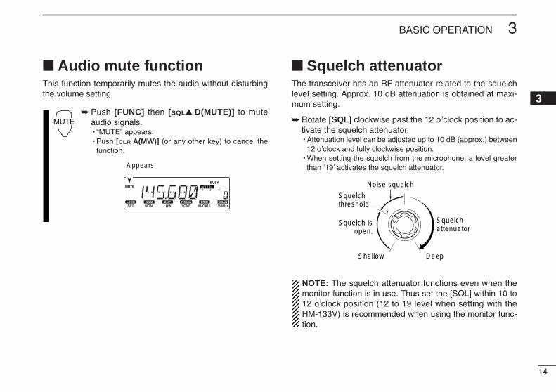
Audio mute functionThis function temporarily mutes the audio without disturbingthe volume setting.
Push [FUNC] then [SQLYY D(MUTE)] to muteaudio signals.• “MUTE” appears.• Push [CLR A(MW)] (or any other key) to cancel the
function.
Squelch attenuatorThe transceiver has an RF attenuator related to the squelchlevel setting. Approx. 10 dB attenuation is obtained at maxi-mum setting.
Rotate [SQL] clockwise past the 12 o’clock position to ac-tivate the squelch attenuator.• Attenuation level can be adjusted up to 10 dB (approx.) between
12 o’clock and fully clockwise position.• When setting the squelch from the microphone, a level greater
than ‘19’ activates the squelch attenuator.
NOTE: The squelch attenuator functions even when themonitor function is in use. Thus set the [SQL] within 10 to12 o’clock position (12 to 19 level when setting with theHM-133V) is recommended when using the monitor func-tion.
Squelch isopen.
Squelchattenuator
Squelch threshold
Shallow Deep
Noise squelch
LOCKSET
ANMMONI
DUPLOW
T-SCANTONE
PRIOM/CALL
SCANV/MHz
DIGITAL PRIO AO BUSYMUTENARMIDLOW
Appears
MUTE

15
3 BASIC OPERATION
S-meter squelch
The transceiver has an S-meter squelch. The S-metersquelch allows you to set minimum signal level needed toopen the squelch.
qTurn the transceiver power OFF.wWhile pushing [SET ], push [PWR] for 1 sec. to
enter initial set mode.
ePush [SET] or [MONI] to select “SSQ” (S-meter squelch)item.
rRotate [DIAL] to set the S-meter level or OFF.
tPush [PWR] to exit initial set mode.
Transmitting
NOTE: To prevent interference, listen on the channel be-fore transmitting by pushing [MONI ], or[MONI 1(ANM)] on the microphone.
q Set the operating frequency. (pgs. 9, 10)• Select output power if desired. See section at right for details.
w Push and hold [PTT] to transmit.• “$” appears.• The S/RF indicator shows the output power selection.• A one-touch PTT function is available. See p. 16 for details.
e Speak into the microphone using your normal voice level.• DO NOT hold the microphone too close to your mouth or speak
too loudly. This may distort the signal.r Release [PTT] to return to receive.
IMPORTANT! (for 65 W transmission):The IC-2200H is equipped with current detector circuit toprotect the power amplifier circuit from high current flowing.When a high SWR (Standing Wave Ratio) antenna or noantenna is connected, or when the connected power sup-ply’s voltage includes, the transceiver reduces transmit out-put power to 10–20 W (approx.) automatically.
ANM
CAUTION: Transmitting without an antenna will damagethe transceiver.
LOCKSET
ANMMONI
DUPLOW
T-SCANTONE
PRIOM/CALL
SCANV/MHz
DIGITAL PRIO AO BUSYMUTENARMIDLOW
LOCKSET
ANMMONI
DUPLOW
T-SCANTONE
PRIOM/CALL
SCANV/MHz
DIGITAL PRIO AO BUSYMUTENARMIDLOW
S-meter squelch OFF (default) S2 level (2 indicator level)
[PWR] [SET LOCK ]
LOCK
USING INITIAL SET MODE

16
3BASIC OPERATION
3
Selecting output powerThe transceiver has 4* output power levels to suit your oper-ating requirements. Low output powers during short-distancecommunications may reduce the possibility of interference toother stations and will reduce current consumption.*The Taiwan version has only 3 levels.
Push [LOW ] several times to select the output power.
*approx., †Korea version• The output power can be changed while transmitting.
The microphone can also be used to select output power.
Push [HIGH 4(DTCS)] for high output power;[MID 5(DTCSSS)] for middle output power(push again for mid. low output power); and[LOW 6(DTMF)] for low output power.• The output power can be changed via the microphone
during receive only.
One-touch PTT functionThe PTT switch can be operated as a one-touch PTT switch(each push switches between transmit/receive). Using thisfunction you can transmit without pushing and holding thePTT switch.
To prevent accidental, continuous transmissions with thisfunction, the transceiver has a time-out timer. See p. 80 fordetails.
z Push [FUNC] then [PRIO 3(PTT-M)] to turn theone-touch PTT function ON.• The activity indicator lights green.
x Push [PTT] to transmit and push again to re-ceive.• Two beeps sound when transmission is started and a
long beep sounds when returning to receive.• “$” flashes when transmitting with the one-touch
PTT function.
c Push [FUNC] then [PRIO 3(PTT-M)] to turn theone-touch PTT function OFF.• The activity indicator goes out.
LOCKSET
ANMMONI
DUPLOW
T-SCANTONE
PRIOM/CALL
SCANV/MHz
DIGITAL PRIO AO BUSYMUTENARMIDLOW
PTT-M
HIGH4
MID5
LOW6
DUP
S/RF INDICATORPOWER OUTPUT
Taiwan
65 W (50 W†) 24 W
25 W* 10 W*
10 W* N/A
5 W* 5 W*
High:
Mid.:
Mid. Low:
Low:

17
REPEATER OPERATION4 Accessing a repeaterq Set the receive frequency (repeater output frequency).
(pgs. 9, 10)w Push [LOW ] for 1 sec., once or twice, to select
minus duplex or plus duplex.• “–” or “+” appears to indicate the transmit frequency for minus
shift or plus shift, respectively.• When the auto repeater function is turned ON (available for the
USA version only), steps w and e are not necessary. (p. 23)
e Push [TONE ] several times to turn ON the sub-audible tone encoder, according to repeater requirements.• “ ” appears • 88.5 Hz is set as the default; refer to p. 19 for tone frequency set-
tings.• When the repeater requires a different tone system, see p. 20.
r Push and hold [PTT] to transmit.• The displayed frequency automatically changes to the transmit
frequency (repeater input frequency).• If “OFF” appears, confirm that the offset frequency (p. 21) is set
correctly.t Release [PTT] to receive.
yPush [MONI ] to check whether the other station’stransmit signal can be received directly.
uTo return to simplex operation, push [LOW ] for1 sec., once or twice, to clear the “–” or “+” indicator.
iTo turn OFF the subaudible tone encoder, push[TONE ] several times until no tone indicators ap-pear.
T-SCAN
DUP
ANM
LOCKSET
ANMMONI
DUPLOW
T-SCANTONE
PRIOM/CALL
SCANV/MHz
DIGITAL PRIO AO BUSYMUTENARMIDLOW
LOCKSET
ANMMONI
DUPLOW
T-SCANTONE
PRIOM/CALL
SCANV/MHz
DIGITAL PRIO AO BUSYMUTENARMIDLOW
While transmittingWhile receiving
LOCKSET
ANMMONI
DUPLOW
T-SCANTONE
PRIOM/CALL
SCANV/MHz
DIGITAL PRIO AO BUSYMUTENARMIDLOW
Appears
T-SCAN
LOCKSET
ANMMONI
DUPLOW
T-SCANTONE
PRIOM/CALL
SCANV/MHz
DIGITAL PRIO AO BUSYMUTENARMIDLOW
Either “–” or “+” appears.
DUP

z Set the receive frequency (repeater output fre-quency). (pgs. 9, 10)
x Push [DUP– 7(TONE)] to select minus duplex;push [DUP+ 8(TSQLSS)] to select plus duplex.
c Push [FUNC] then [DUP– 7(TONE)] to turn ONthe subaudible tone encoder according to re-peater requirements.• Refer to p. 19 for the tone frequency setting.• When the repeater requires a different tone system,
see p. 20.
v Push and hold [PTT] to transmit.b Release [PTT] to receive.n Push [MONI 1(ANM)] to check whether the other
station’s transmit signal can be received directly.
m Push [SIMP 9(TSQL)] to return to simplex oper-ation.• “+” or “–” indicator disappears.
, To turn OFF the subaudible tone encoder, push[FUNC] then [ENT C(T-OFF)].
SIMP9
LOCKSET
ANMMONI
DUPLOW
T-SCANTONE
PRIOM/CALL
SCANV/MHz
DIGITAL PRIO AO BUSYMUTENARMIDLOW
Push ,
then .
LOCKSET
ANMMONI
DUPLOW
T-SCANTONE
PRIOM/CALL
SCANV/MHz
DIGITAL PRIO AO BUSYMUTENARMIDLOW
LOCKSET
ANMMONI
DUPLOW
T-SCANTONE
PRIOM/CALL
SCANV/MHz
DIGITAL PRIO AO BUSYMUTENARMIDLOW
Push
Push
DUP–7
DUP+8
18
4REPEATER OPERATION
4
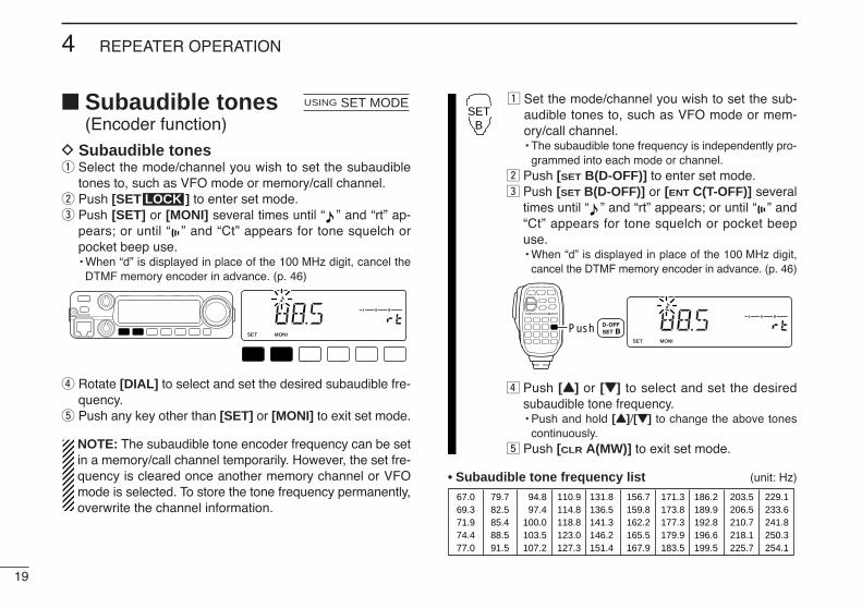
Subaudible tones(Encoder function)
D Subaudible tonesq Select the mode/channel you wish to set the subaudible
tones to, such as VFO mode or memory/call channel.w Push [SET ] to enter set mode.e Push [SET] or [MONI] several times until “ ” and “rt” ap-
pears; or until “ ” and “Ct” appears for tone squelch orpocket beep use.• When “d” is displayed in place of the 100 MHz digit, cancel the
DTMF memory encoder in advance. (p. 46)
r Rotate [DIAL] to select and set the desired subaudible fre-quency.
t Push any key other than [SET] or [MONI] to exit set mode.
NOTE: The subaudible tone encoder frequency can be setin a memory/call channel temporarily. However, the set fre-quency is cleared once another memory channel or VFOmode is selected. To store the tone frequency permanently,overwrite the channel information.
z Set the mode/channel you wish to set the sub-audible tones to, such as VFO mode or mem-ory/call channel.• The subaudible tone frequency is independently pro-
grammed into each mode or channel.x Push [SET B(D-OFF)] to enter set mode.c Push [SET B(D-OFF)] or [ENT C(T-OFF)] several
times until “ ” and “rt” appears; or until “ ” and“Ct” appears for tone squelch or pocket beepuse.• When “d” is displayed in place of the 100 MHz digit,
cancel the DTMF memory encoder in advance. (p. 46)
v Push [YY] or [ZZ] to select and set the desiredsubaudible tone frequency.• Push and hold [YY]/[ZZ] to change the above tones
continuously.b Push [CLR A(MW)] to exit set mode.
• Subaudible tone frequency list (unit: Hz)
67.069.371.974.477.0
79.782.585.488.591.5
94.897.4
100.0103.5107.2
110.9114.8118.8123.0127.3
131.8136.5141.3146.2151.4
156.7159.8162.2165.5167.9
171.3173.8177.3179.9183.5
186.2189.9192.8196.6199.5
203.5206.5210.7218.1225.7
229.1233.6241.8250.3254.1
LOCKSET
ANMMONI
DUPLOW
T-SCANTONE
PRIOM/CALL
SCANV/MHz
DIGITAL PRIO AO BUSYMUTENARMIDLOWPush
SETB
LOCKSET
ANMMONI
DUPLOW
T-SCANTONE
PRIOM/CALL
SCANV/MHz
DIGITAL PRIO AO BUSYMUTENARMIDLOW
LOCK
USING SET MODE
19
4 REPEATER OPERATION
20
4REPEATER OPERATION
4
D DTMF tones Push [DTMF-S], then push the keys of the de-
sired DTMF digits.• The function indicator lights green.• 0–9, A–D, M(E) and #(F) are available.• When “d” is displayed in place of the 100 MHz digit,
cancel the DTMF memory encoder in advance.(p. 46)
• Push [DTMF-S] again to return the keypad to nor-mal function control.
• The transceiver has 10 DTMF memory channelsfor autopatch operation. See p. 45 for details.
D 1750 Hz toneThe microphone has 1750 Hz tone capability, used for ringtone when calling, etc.
z Push [FUNC].• The function indicator lights orange.
x Push [MM(TONE-1)] to transmit a 1750 Hz tonecall signal for 0.5 sec.; push and hold[0(TONE-2)] to transmit a 1750 Hz tone callsignal for an arbitrary period.• The function indicator goes out automatically.
Push ,
then or .
TONE-1
TONE-2
then push desired keys.
Push ,
DTMF-S

Offset frequencyWhen communicating thorough a repeater, the transmit fre-quency is shifted from the receive frequency by an amountdetermined by the offset frequency.
q Push [SET ] to enter set mode.w Push [SET] or [MONI] until “±” and offset frequency appear.
e Rotate [DIAL] to set the desired offset frequency.• Push [V/MHz] to select the 1 MHz tuning steps.
r Push any key other than indicated function keys to exitset mode.
z Push [SET B(D-OFF)] to enter set mode.x Push [SET B(D-OFF)] or [ENT C(T-OFF)] until “±”
and offset frequency appear.
c Push [YY] or [ZZ] to set the desired offset.• Direct frequency entry from the keypad is not possi-
ble.v Push [CLR A(MW)] to exit set mode.
Repeater lockout
This function helps prevent interference to other stations byinhibiting your transmission when a signal is received. Thetransceiver has two inhibiting conditions, repeater and busy.
q Push [PWR] to turn power OFF.w While pushing [SET ], turn power ON to enter ini-
tial set mode.
e Push [SET] or [MONI] several times until the “RLO” dis-play appears as shown below.
r Rotate [DIAL] to turn the repeater lockout function to “RP,”“BU” or OFF.
• “RP”: Transmit is inhibited when a signal with un-matched sub-audible tone is received.
• “BU”: Transmit is inhibited when a signal is received.t Push [PWR] to exit initial set mode.
LOCKSET
ANMMONI
DUPLOW
T-SCANTONE
PRIOM/CALL
SCANV/MHz
DIGITAL PRIO AO BUSYMUTENARMIDLOW
LOCKSET
ANMMONI
DUPLOW
T-SCANTONE
PRIOM/CALL
SCANV/MHz
DIGITAL PRIO AO BUSYMUTENARMIDLOW
[PWR] [SET LOCK ]
LOCK
USING INITIAL SET MODE
LOCKSET
ANMMONI
DUPLOW
T-SCANTONE
PRIOM/CALL
SCANV/MHz
DIGITAL PRIO AO BUSYMUTENARMIDLOWPush
SETB
LOCKSET
ANMMONI
DUPLOW
T-SCANTONE
PRIOM/CALL
SCANV/MHz
DIGITAL PRIO AO BUSYMUTENARMIDLOW
[DIAL]
LOCK
USING SET MODE
21
4 REPEATER OPERATION
22
4REPEATER OPERATION
4
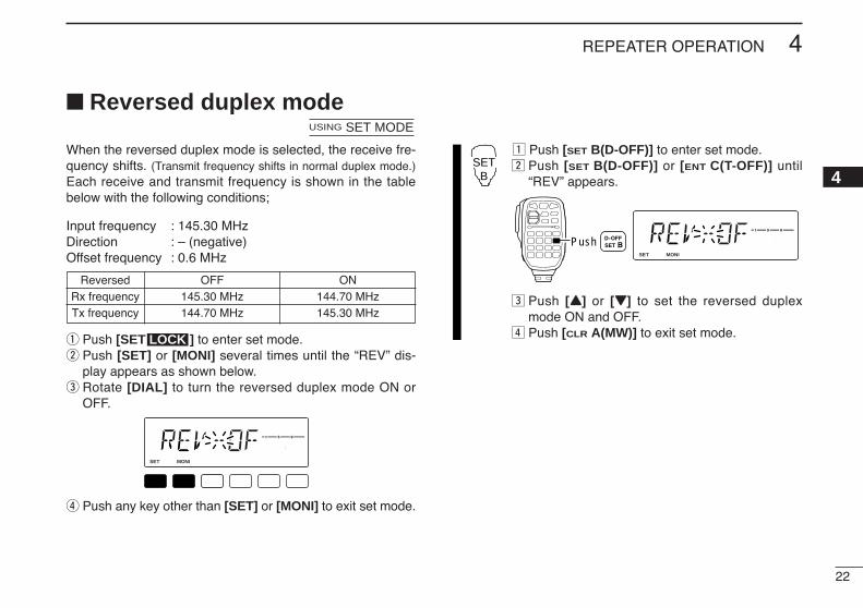
Reversed duplex mode
When the reversed duplex mode is selected, the receive fre-quency shifts. (Transmit frequency shifts in normal duplex mode.)Each receive and transmit frequency is shown in the tablebelow with the following conditions;
Input frequency : 145.30 MHzDirection : – (negative)Offset frequency : 0.6 MHz
q Push [SET ] to enter set mode.w Push [SET] or [MONI] several times until the “REV” dis-
play appears as shown below.e Rotate [DIAL] to turn the reversed duplex mode ON or
OFF.
r Push any key other than [SET] or [MONI] to exit set mode.
z Push [SET B(D-OFF)] to enter set mode.x Push [SET B(D-OFF)] or [ENT C(T-OFF)] until
“REV” appears.
c Push [YY] or [ZZ] to set the reversed duplexmode ON and OFF.
v Push [CLR A(MW)] to exit set mode.
LOCKSET
ANMMONI
DUPLOW
T-SCANTONE
PRIOM/CALL
SCANV/MHz
DIGITAL PRIO AO BUSYMUTENARMIDLOWPush
SETB
LOCKSET
ANMMONI
DUPLOW
T-SCANTONE
PRIOM/CALL
SCANV/MHz
DIGITAL PRIO AO BUSYMUTENARMIDLOW
LOCK
USING SET MODE
Reversed OFF ONRx frequency 145.30 MHz 144.70 MHzTx frequency 144.70 MHz 145.30 MHz
23
4 REPEATER OPERATION
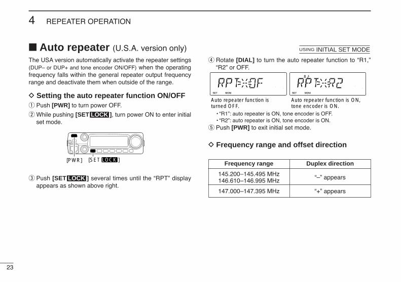
Auto repeater (U.S.A. version only)The USA version automatically activate the repeater settings(DUP– or DUP+ and tone encoder ON/OFF) when the operatingfrequency falls within the general repeater output frequencyrange and deactivate them when outside of the range.
D Setting the auto repeater function ON/OFFq Push [PWR] to turn power OFF.
w While pushing [SET ], turn power ON to enter initialset mode.
e Push [SET ] several times until the “RPT” displayappears as shown above right.
r Rotate [DIAL] to turn the auto repeater function to “R1,”“R2” or OFF.
• “R1”: auto repeater is ON, tone encoder is OFF.• “R2”: auto repeater is ON, tone encoder is ON.
t Push [PWR] to exit initial set mode.
D Frequency range and offset direction
LOCKSET
ANMMONI
DUPLOW
T-SCANTONE
PRIOM/CALL
SCANV/MHz
DIGITAL PRIO AO BUSYMUTENARMIDLOW
LOCKSET
ANMMONI
DUPLOW
T-SCANTONE
PRIOM/CALL
SCANV/MHz
DIGITAL PRIO AO BUSYMUTENARMIDLOW
Auto repeater function is turned OFF.
Auto repeater function is ON,tone encoder is ON.
USING INITIAL SET MODE
LOCK
[PWR] [SET LOCK ]
LOCK
Frequency range Duplex direction
145.200–145.495 MHz “–” appears146.610–146.995 MHz
147.000–147.395 MHz “+” appears

24
5MEMORY OPERATION
45
General descriptionThe transceiver has 207 memory channels including 6 scanedge memory channels (3 pairs), and 1 call channel. Each ofthese channels can be individually programmed with operat-ing frequency (pgs. 9, 10), duplex direction (p. 17) and offset(p. 21), subaudible tone encoder or tone squelch and its tonefrequency (pgs. 19, 48–50) and skip information* (p. 41). In addition, a total of 10 memory banks, A to J, are availablefor usage by group, etc.
*except for scan edge memory channels.
Memory channel selectionD Using the tuning dial
q Push [M/CALL ]once or twice to selectmemory mode.• “M” indicator appears.
w Rotate [DIAL] to selectthe desired memory chan-nel.• Programmed memory
channels only can be se-lected.
D Using the [Y]/[Z] keysz Push [MR/CALL] to select memory mode.x Push [YY] or [ZZ] to select and set the desired
memory channel.• Pushing [YY]/[ZZ] for 1 sec. activates a scan.• If scan is activated, push [YY]/[ZZ] again or push
[CLR A(MW)] to stop it.
D Using the keypadz Push [MR/CALL] to select memory mode.x Push [ENT C(T-OFF)] to activate the keypad
for numeral input.c Push 3 appropriate digit keys to input a chan-
nel number. • When inputting non-programmed channel num-
bers, the previous memory channel appears.• Push only 1 appropriate digit key, [MONI 1(ANM)],
[SCAN 2(T-SCAN)] or [PRIO 3(PTT-M)], then push[MM(TONE-1)] or [SQLZZ #(16KEY-L)] to select scanedge channels. “MM” and “#” can be used for “A”and “b” respectively.
MR/CALL
Y/Z
MR/CALL
Y/Z
PRIO
LOCKSET
ANMMONI
DUPLOW
T-SCANTONE
PRIOM/CALL
SCANV/MHz
DIGITAL PRIO AO BUSYMUTENARMIDLOW
[DIAL]
Appears
25
5 MEMORY OPERATION
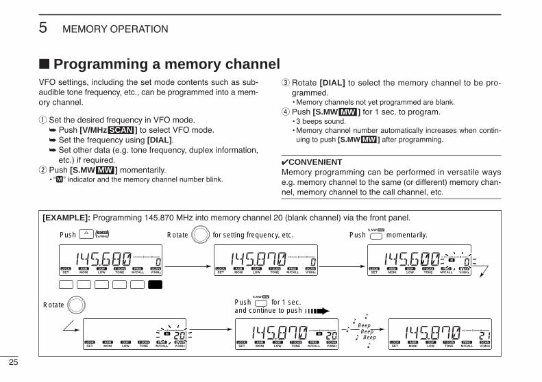
Programming a memory channelVFO settings, including the set mode contents such as sub-audible tone frequency, etc., can be programmed into a mem-ory channel.
q Set the desired frequency in VFO mode. Push [V/MHz ] to select VFO mode. Set the frequency using [DIAL]. Set other data (e.g. tone frequency, duplex information,
etc.) if required.w Push [S.MW ] momentarily.
• “M” indicator and the memory channel number blink.
e Rotate [DIAL] to select the memory channel to be pro-grammed.• Memory channels not yet programmed are blank.
r Push [S.MW ] for 1 sec. to program.• 3 beeps sound.• Memory channel number automatically increases when contin-
uing to push [S.MW ] after programming.
CONVENIENTMemory programming can be performed in versatile wayse.g. memory channel to the same (or different) memory chan-nel, memory channel to the call channel, etc.
MW
MW
MW
SCAN
[EXAMPLE]: Programming 145.870 MHz into memory channel 20 (blank channel) via the front panel.
LOCKSET
ANMMONI
DUPLOW
T-SCANTONE
PRIOM/CALL
SCANV/MHz
SCANV/MHz
MWS.MW
DIGITAL PRIO AO BUSYMUTENARMIDLOW
LOCKSET
ANMMONI
DUPLOW
T-SCANTONE
PRIOM/CALL
SCANV/MHz
DIGITAL PRIO AO BUSYMUTENARMIDLOW
LOCKSET
ANMMONI
DUPLOW
T-SCANTONE
PRIOM/CALL
SCANV/MHz
DIGITAL PRIO AO BUSYMUTENARMIDLOW
LOCKSET
ANMMONI
DUPLOW
T-SCANTONE
PRIOM/CALL
SCANV/MHz
DIGITAL PRIO AO BUSYMUTENARMIDLOW
LOCKSET
ANMMONI
DUPLOW
T-SCANTONE
PRIOM/CALL
SCANV/MHz
DIGITAL PRIO AO BUSYMUTENARMIDLOW
LOCKSET
ANMMONI
DUPLOW
T-SCANTONE
PRIOM/CALL
SCANV/MHz
DIGITAL PRIO AO BUSYMUTENARMIDLOW
MWS.MW
( )Push Rotate for setting frequency, etc. Push momentarily.
Rotate Push for 1 sec. and continue to push
BeepBeepBeep
“
““
“
“
26
5MEMORY OPERATION
5
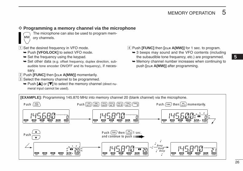
D Programming a memory channel via the microphone
[EXAMPLE]: Programming 145.870 MHz into memory channel 20 (blank channel) via the microphone.
LOCKSET
ANMMONI
DUPLOW
T-SCANTONE
PRIOM/CALL
SCANV/MHz
DIGITAL PRIO AO BUSYMUTENARMIDLOW
LOCKSET
ANMMONI
DUPLOW
T-SCANTONE
PRIOM/CALL
SCANV/MHz
DIGITAL PRIO AO BUSYMUTENARMIDLOW
LOCKSET
ANMMONI
DUPLOW
T-SCANTONE
PRIOM/CALL
SCANV/MHz
DIGITAL PRIO AO BUSYMUTENARMIDLOW
LOCKSET
ANMMONI
DUPLOW
T-SCANTONE
PRIOM/CALL
SCANV/MHz
DIGITAL PRIO AO BUSYMUTENARMIDLOW
LOCKSET
ANMMONI
DUPLOW
T-SCANTONE
PRIOM/CALL
SCANV/MHz
DIGITAL PRIO AO BUSYMUTENARMIDLOW
LOCKSET
ANMMONI
DUPLOW
T-SCANTONE
PRIOM/CALL
SCANV/MHz
DIGITAL PRIO AO BUSYMUTENARMIDLOW
BeepBeepBeep
“
““
“
“
Push Push Push then momentarily.
PushPush then 1 sec. and continue to push
The microphone can also be used to program mem-ory channels.
z Set the desired frequency in VFO mode. Push [VFO/LOCK] to select VFO mode. Set the frequency using the keypad. Set other data (e.g. offset frequency, duplex direction, sub-
audible tone encoder ON/OFF and its frequency), if neces-sary.
x Push [FUNC] then [CLR A(MW)] momentarily.c Select the memory channel to be programmed.
Push [YY] or [ZZ] to select the memory channel (direct nu-meral input cannot be used).
v Push [FUNC] then [CLR A(MW)] for 1 sec. to program. 3 beeps may sound and the VFO contents (including
the subaudible tone frequency, etc.) are programmed. Memory channel number increases when continuing to
push [CLR A(MW)] after programming.
MW

27
5 MEMORY OPERATION
Transferring memory contentsThis function transfers a memory channel’s contents to VFO(or another memory/call channel). This is useful when search-ing for signals around a memory channel frequency and forrecalling the offset frequency, subaudible tone frequency etc.
D Memory/callVFOq Select the memory/call channel to be transferred.
Push [M/CALL ] to select memory mode, then ro-tate [DIAL] to select the desired memory channel.
Push [M/CALL ] for 1 sec. to select the call chan-nel.
w Push [S.MW ] for 1 sec. to transfer the selected mem-ory/call channel contents to the VFO.• VFO mode is selected automatically.
z Select the memory/call channel to betransferred. Push [MR/CALL] to select memory mode,
then select the desired memory channelvia [YY]/[ZZ] or keypad.
Push [MR/CALL] for 1 sec. to select thecall channel.
x Push [FUNC], then [CLR A(MW)] for 1 sec. totransfer the selected memory/call channelcontents to the VFO.• VFO mode is selected automatically.
MR/CALL
MW
[Y]/[Z]MW
PRIO
PRIO
[EXAMPLE]: Transferring memory channel 30 contents to VFO.
LOCKSET
ANMMONI
DUPLOW
T-SCANTONE
PRIOM/CALL
SCANV/MHz
PRIOM/CALL
MWS.MW
DIGITAL PRIO AO BUSYMUTENARMIDLOW
LOCKSET
ANMMONI
DUPLOW
T-SCANTONE
PRIOM/CALL
SCANV/MHz
DIGITAL PRIO AO BUSYMUTENARMIDLOW
LOCKSET
ANMMONI
DUPLOW
T-SCANTONE
PRIOM/CALL
SCANV/MHz
DIGITAL PRIO AO BUSYMUTENARMIDLOW
( )Push to select memory mode. Rotate for setting memory channel. Push for 1 sec.
HM-133V operation:
Front panel operation:
Push to select memory mode. Select memory channel. Push then push for 1 sec.
28
5MEMORY OPERATION
5
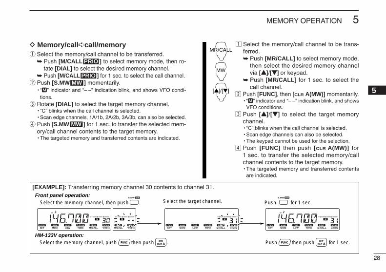
D Memory/callcall/memoryq Select the memory/call channel to be transferred.
Push [M/CALL ] to select memory mode, then ro-tate [DIAL] to select the desired memory channel.
Push [M/CALL ] for 1 sec. to select the call channel.w Push [S.MW ] momentarily.
• “M” indicator and “– –” indication blink, and shows VFO condi-tions.
e Rotate [DIAL] to select the target memory channel.• “C” blinks when the call channel is selected.• Scan edge channels, 1A/1b, 2A/2b, 3A/3b, can also be selected.
r Push [S.MW ] for 1 sec. to transfer the selected mem-ory/call channel contents to the target memory.• The targeted memory and transferred contents are indicated.
z Select the memory/call channel to be trans-ferred. Push [MR/CALL] to select memory mode,
then select the desired memory channelvia [YY]/[ZZ] or keypad.
Push [MR/CALL] for 1 sec. to select thecall channel.
x Push [FUNC], then [CLR A(MW)] momentarily.• “M” indicator and “– –” indication blink, and shows
VFO conditions.c Push [YY]/[ZZ] to select the target memory
channel.• “C” blinks when the call channel is selected.• Scan edge channels can also be selected.• The keypad cannot be used for the selection.
v Push [FUNC] then push [CLR A(MW)] for1 sec. to transfer the selected memory/callchannel contents to the target memory.• The targeted memory and transferred contents
are indicated.
MR/CALL
MW
[Y]/[Z]
MW
MWPRIO
PRIO
[EXAMPLE]: Transferring memory channel 30 contents to channel 31.
PRIOM/CALL
SCANV/MHz
AO BUSY
LOCKSET
ANMMONI
DUPLOW
T-SCANTONE
PRIOM/CALL
SCANV/MHz
DIGITAL PRIO AO BUSYMUTENARMIDLOW
LOCKSET
ANMMONI
DUPLOW
T-SCANTONE
PRIOM/CALL
SCANV/MHz
DIGITAL PRIO AO BUSYMUTENARMIDLOW
LOCKSET
ANMMONI
DUPLOW
T-SCANTONE
PRIOM/CALL
SCANV/MHz
DIGITAL PRIO AO BUSYMUTENARMIDLOW
MWS.MW MWS.MW
Select the memory channel, then push . Select the target channel. Push for 1 sec.
HM-133V operation:
Front panel operation:
Push then push for 1 sec.Select the memory channel, push then push .
29
5 MEMORY OPERATION
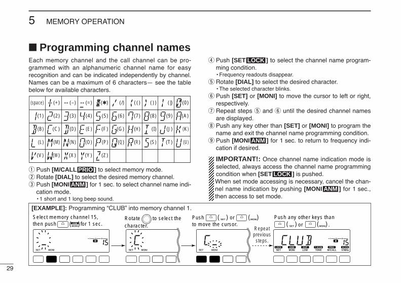
Programming channel names Each memory channel and the call channel can be pro-grammed with an alphanumeric channel name for easyrecognition and can be indicated independently by channel.Names can be a maximum of 6 characters— see the tablebelow for available characters.
q Push [M/CALL ] to select memory mode.w Rotate [DIAL] to select the desired memory channel.e Push [MONI ] for 1 sec. to select channel name indi-
cation mode.• 1 short and 1 long beep sound.
r Push [SET ] to select the channel name program-ming condition.• Frequency readouts disappear.
t Rotate [DIAL] to select the desired character.• The selected character blinks.
y Push [SET] or [MONI] to move the cursor to left or right,respectively.
u Repeat steps t and y until the desired channel namesare displayed.
i Push any key other than [SET] or [MONI] to program thename and exit the channel name programming condition.
o Push [MONI ] for 1 sec. to return to frequency indi-cation if desired.
IMPORTANT!: Once channel name indication mode isselected, always access the channel name programmingcondition when [SET ] is pushed. When set mode accessing is necessary, cancel the chan-nel name indication by pushing [MONI ] for 1 sec.,then access to set mode.
ANM
LOCK
ANM
LOCK
ANM
PRIO
(1)
(B)
(L)
(V)
(+)
(2)
(C)
(M)
(W)
(–)
(3)
(D)
(N)
(X)
(=)
(4)
(E)
(O)
(Y)
()
(5)
(F)
(P)
(Z)
(/)
(6)
(G)
(Q)
(space)
(7)
(()
(H)
(R)
())
(8)
(I)
(S)
(|)
(9)
(J)
(T)
(0)
(A)
(K)
(U)
[EXAMPLE]: Programming “CLUB” into memory channel 1.
LOCKSET
ANMMONI
DUPLOW
T-SCANTONE
PRIOM/CALL
SCANV/MHz
DIGITAL PRIO AO BUSYMUTENARMIDLOW
LOCKSET
ANMMONI
DUPLOW
T-SCANTONE
PRIOM/CALL
SCANV/MHz
DIGITAL PRIO AO BUSYMUTENARMIDLOW
LOCKSET
ANMMONI
DUPLOW
MUTENARMIDLOW
LOCKSET
ANMMONI
DUPLOW
MUTENARMIDLOW
ANMMONI( )
LOCKSET( ) ANM
MONI( )LOCKSET( ) ANM
MONI( )Push any other keys than or .
Select memory channel 15, then push for 1 sec.
Push or to move the cursor.
Rotate to select the character. Repeat
previoussteps.
30
5MEMORY OPERATION
5
Channel names can also be programmed via the mi-crophone.
z Select the memory/call channel to be assigned memorynames. Push [MR/CALL] to select memory mode, then select
the desired memory channel via [YY]/[ZZ] or keypad.• Scan edge channels can also be selected.
Push [MR/CALL] for 1 sec. to select the call channel.x Push [FUNC], then [MONI 1(ANM)] momentarily.c Push [SET B(D-OFF)].
• Frequency readouts disappear.v Push [YY]/[ZZ] to select the desired character.
• The selected character blinks.
b Push [SET B(D-OFF)] or [ENT C(T-OFF)] to move the cur-sor to left or right, respectively.
n Repeat steps v and b until the desired channel namesare displayed.
m Push [CLR A(MW)] to program the name and exit thechannel name programming condition.
, Push [FUNC], then push [MONI 1(ANM)] to return to fre-quency indication if desired.
[EXAMPLE]: Programming “CLUB” into memory channel 15.
LOCKSET
ANMMONI
DUPLOW
T-SCANTONE
PRIOM/CALL
SCANV/MHz
DIGITAL PRIO AO BUSYMUTENARMIDLOW
LOCKSET
ANMMONI
DUPLOW
T-SCANTONE
PRIOM/CALL
SCANV/MHz
DIGITAL PRIO AO BUSYMUTENARMIDLOW
LOCKSET
ANMMONI
DUPLOW
MUTENARMIDLOW
LOCKSET
ANMMONI
DUPLOW
MUTENARMIDLOW
Repeatprevioussteps.
Push to select the character.Select memory channel 15, push , then push . Push .
Push or to move the cursor.

31
5 MEMORY OPERATION
Memory clearingContents of programmed memories can be cleared (blanked),if desired.
q Push [V/MHz ] to select VFO mode.w Push [S.MW ] momentarily.
• “M” indicator and the memory channel number blink.e Rotate [DIAL] to select the memory channel to be cleared.
• Memory channels not yet programmed are blank.
r Push [S.MW ] momentarily, then push [S.MW ]again for 1 sec. This operation must be performed within 1.5 sec.• 3 beeps sound, then the frequency is cleared.• “M” indicator blinks continuously.• When clearing the call channel, the current VFO conditions are
re-programmed into the call channel automatically.t Push any key, except [S.MW ], to return to VFO
mode.
NOTE: Be careful!— the contents of cleared memoriesCANNOT be recalled.
MW
MWMW
MWSCAN
[EXAMPLE]: Clearing memory channel 20.
LOCKSET
ANMMONI
DUPLOW
T-SCANTONE
PRIOM/CALL
SCANV/MHz
SCANV/MHz
DIGITAL PRIO AO BUSYMUTENARMIDLOW
LOCKSET
ANMMONI
DUPLOW
T-SCANTONE
PRIOM/CALL
SCANV/MHz
DIGITAL PRIO AO BUSYMUTENARMIDLOW
LOCKSET
ANMMONI
DUPLOW
T-SCANTONE
PRIOM/CALL
SCANV/MHz
DIGITAL PRIO AO BUSYMUTENARMIDLOW
LOCKSET
ANMMONI
DUPLOW
T-SCANTONE
PRIOM/CALL
SCANV/MHz
DIGITAL PRIO AO BUSYMUTENARMIDLOW
LOCKSET
ANMMONI
DUPLOW
T-SCANTONE
PRIOM/CALL
SCANV/MHz
DIGITAL PRIO AO BUSYMUTENARMIDLOW
MWS.MW
MWS.MW MWS.MWMWS.MW
( )Push to select VFO. Push momentarily. Rotate for selecting memory channel..
Push momentarily, then push again for 1 sec. Push any other keys than .
BeepBeepBeep
“
““
“
“
32
5MEMORY OPERATION
5
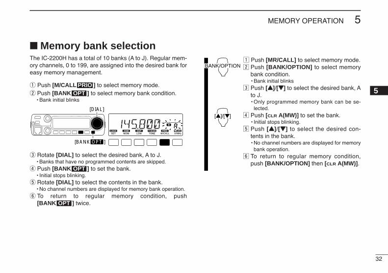
Memory bank selectionThe IC-2200H has a total of 10 banks (A to J). Regular mem-ory channels, 0 to 199, are assigned into the desired bank foreasy memory management.
q Push [M/CALL ] to select memory mode.w Push [BANK ] to select memory bank condition.
• Bank initial blinks
e Rotate [DIAL] to select the desired bank, A to J.• Banks that have no programmed contents are skipped.
r Push [BANK ] to set the bank.• Initial stops blinking.
t Rotate [DIAL] to select the contents in the bank.• No channel numbers are displayed for memory bank operation.
y To return to regular memory condition, push [BANK ] twice.
z Push [MR/CALL] to select memory mode.x Push [BANK/OPTION] to select memory
bank condition.• Bank initial blinks
c Push [YY]/[ZZ] to select the desired bank, Ato J.• Only programmed memory bank can be se-
lected.v Push [CLR A(MW)] to set the bank.
• Initial stops blinking.b Push [YY]/[ZZ] to select the desired con-
tents in the bank.• No channel numbers are displayed for memory
bank operation.n To return to regular memory condition,
push [BANK/OPTION] then [CLR A(MW)].
BANK/OPTION
[Y]/[Z]
OPT
OPT
LOCKSET
ANMMONI
DUPLOW
T-SCANTONE
PRIOM/CALL
SCANV/MHz
DIGITAL PRIO AO BUSYMUTENARMIDLOW
[BANK OPT ]
[DIAL]
OPTPRIO

33
5 MEMORY OPERATION
Memory bank settingq Push [M/CALL ] to select memory mode, then se-
lect the desired memory channel via [DIAL].w Push [SET ] enter the set mode.e Push [SET] or [MONI] several times until “BAK” appears.
• “– –” indication blinks as follows.
r Rotate [DIAL] to select the desired bank to be set.
t Push any key other than [SET] or [MONI] to set the chan-nel into the bank and return to regular memory condition.
y Repeat steps q to t to set another memory channel intothe same or another bank.
z Push [MR/CALL] then select the desiredmemory channel via [YY]/[ZZ] or keypad.
x Push [SET B(D-OFF)] to enter set mode.c Push [SET B(D-OFF)] or [ENT C(T-OFF)] sev-
eral times until “BAK” appears.v Push [YY] or [ZZ] to select the desired bank to
be set.b Push [CLR A(MW)] to set the channel into the
bank and exit set mode.n Repeat steps z to b to set an another mem-
ory channel into the same or another bank.
MR/CALL
[Y]/[Z]
SET
LOCKSET
ANMMONI
DUPLOW
T-SCANTONE
PRIOM/CALL
SCANV/MHz
DIGITAL PRIO AO BUSYMUTENARMIDLOW
[DIAL]
LOCKSET
ANMMONI
DUPLOW
T-SCANTONE
PRIOM/CALL
SCANV/MHz
DIGITAL PRIO AO BUSYMUTENARMIDLOW
LOCK
PRIO
34
5MEMORY OPERATION
5
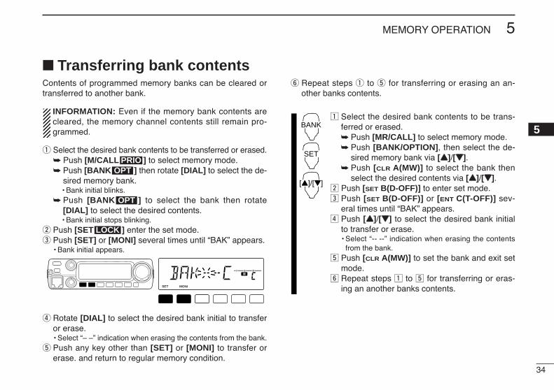
Transferring bank contentsContents of programmed memory banks can be cleared ortransferred to another bank.
INFORMATION: Even if the memory bank contents arecleared, the memory channel contents still remain pro-grammed.
q Select the desired bank contents to be transferred or erased. Push [M/CALL ] to select memory mode. Push [BANK ] then rotate [DIAL] to select the de-
sired memory bank.• Bank initial blinks.
Push [BANK ] to select the bank then rotate[DIAL] to select the desired contents.• Bank initial stops blinking.
w Push [SET ] enter the set mode.e Push [SET] or [MONI] several times until “BAK” appears.
• Bank initial appears.
r Rotate [DIAL] to select the desired bank initial to transferor erase.• Select “– –” indication when erasing the contents from the bank.
t Push any key other than [SET] or [MONI] to transfer orerase. and return to regular memory condition.
y Repeat steps q to t for transferring or erasing an an-other banks contents.
z Select the desired bank contents to be trans-ferred or erased. Push [MR/CALL] to select memory mode. Push [BANK/OPTION], then select the de-
sired memory bank via [YY]/[ZZ]. Push [CLR A(MW)] to select the bank then
select the desired contents via [YY]/[ZZ].x Push [SET B(D-OFF)] to enter set mode.c Push [SET B(D-OFF)] or [ENT C(T-OFF)] sev-
eral times until “BAK” appears. v Push [YY]/[ZZ] to select the desired bank initial
to transfer or erase.• Select “-- --” indication when erasing the contents
from the bank.b Push [CLR A(MW)] to set the bank and exit set
mode.n Repeat steps z to b for transferring or eras-
ing an another banks contents.
BANK
[Y]/[Z]
SET
LOCKSET
ANMMONI
DUPLOW
T-SCANTONE
PRIOM/CALL
SCANV/MHz
DIGITAL PRIO AO BUSYMUTENARMIDLOW
LOCK
OPT
OPTPRIO
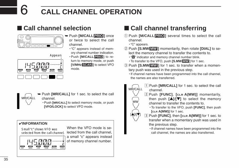
35
CALL CHANNEL OPERATION6 Call channel selection
Push [M/CALL ] onceor twice to select the callchannel.• “C” appears instead of mem-
ory channel number indication.• Push [M/CALL ] to re-
turn to memory mode, or push[V/MHz ] to select VFOmode.
Push [MR/CALL] for 1 sec. to select the callchannel.• Push [MR/CALL] to select memory mode, or push
[VFO/LOCK] to select VFO mode.
Call channel transferringq Push [M/CALL ] several times to select the call
channel.• “C” appears.
w Push [S.MW ] momentarily, then rotate [DIAL] to se-lect the memory channel to transfer the contents to.• “M” indicator and memory channel number blink.• To transfer to the VFO, push [S.MW ] for 1 sec.
e Push [S.MW ] for 1 sec. to transfer when a momen-tary push was used in the previous step.• If channel names have been programmed into the call channel,
the names are also transferred.
z Push [MR/CALL] for 1 sec. to select the callchannel.
x Push [FUNC], [CLR A(MW)] momentarily,then push [YY]/[ZZ] to select the memorychannel to transfer the contents to.• To transfer to the VFO, push [FUNC], then push
[CLR A(MW)] for 1 sec. c Push [FUNC], then [CLR A(MW)] for 1 sec. to
transfer when a momentary push was used inthe previous step.• If channel names have been programmed into the
call channel, the names are also transferred.
MR/CALL
MW
[Y]/[Z]
MWMW
MW
PRIO
MR/CALL
SCAN
PRIO
PRIO
LOCKSET
ANMMONI
DUPLOW
T-SCANTONE
PRIOM/CALL
SCANV/MHz
DIGITAL PRIO AO BUSYMUTENARMIDLOW
Appears
INFORMATIONWhen the VFO mode is se-lected from the call channel,a small “c” appears insteadof memory channel number.
LOCKSET
ANMMONI
DUPLOW
T-SCANTONE
PRIOM/CALL
SCANV/MHz
DIGITAL PRIO AO BUSYMUTENARMIDLOW
Small “c” shows VFO was selected from the call channel.
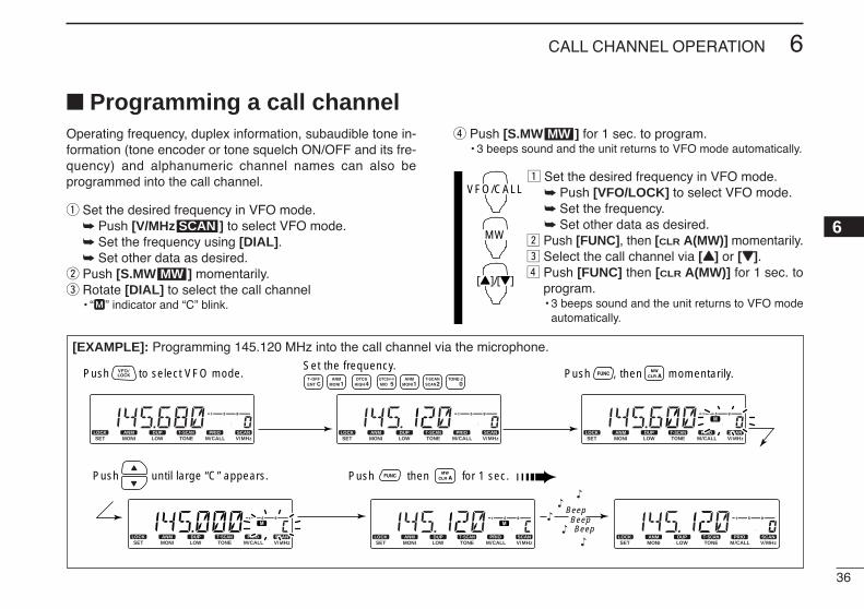
36
6CALL CHANNEL OPERATION
6
Programming a call channelOperating frequency, duplex information, subaudible tone in-formation (tone encoder or tone squelch ON/OFF and its fre-quency) and alphanumeric channel names can also beprogrammed into the call channel.
q Set the desired frequency in VFO mode. Push [V/MHz ] to select VFO mode. Set the frequency using [DIAL]. Set other data as desired.
w Push [S.MW ] momentarily.e Rotate [DIAL] to select the call channel
• “M” indicator and “C” blink.
r Push [S.MW ] for 1 sec. to program.• 3 beeps sound and the unit returns to VFO mode automatically.
z Set the desired frequency in VFO mode. Push [VFO/LOCK] to select VFO mode. Set the frequency. Set other data as desired.
x Push [FUNC], then [CLR A(MW)] momentarily.c Select the call channel via [YY] or [ZZ].v Push [FUNC] then [CLR A(MW)] for 1 sec. to
program.• 3 beeps sound and the unit returns to VFO mode
automatically.
VFO/CALL
MW
[Y]/[Z]
MW
MW
SCAN
[EXAMPLE]: Programming 145.120 MHz into the call channel via the microphone.
LOCKSET
ANMMONI
DUPLOW
T-SCANTONE
PRIOM/CALL
SCANV/MHz
DIGITAL PRIO AO BUSYMUTENARMIDLOW
LOCKSET
ANMMONI
DUPLOW
T-SCANTONE
PRIOM/CALL
SCANV/MHz
DIGITAL PRIO AO BUSYMUTENARMIDLOW
LOCKSET
ANMMONI
DUPLOW
T-SCANTONE
PRIOM/CALL
SCANV/MHz
DIGITAL PRIO AO BUSYMUTENARMIDLOW
LOCKSET
ANMMONI
DUPLOW
T-SCANTONE
PRIOM/CALL
SCANV/MHz
DIGITAL PRIO AO BUSYMUTENARMIDLOW
LOCKSET
ANMMONI
DUPLOW
T-SCANTONE
PRIOM/CALL
SCANV/MHz
DIGITAL PRIO AO BUSYMUTENARMIDLOW
LOCKSET
ANMMONI
DUPLOW
T-SCANTONE
PRIOM/CALL
SCANV/MHz
DIGITAL PRIO AO BUSYMUTENARMIDLOW
BeepBeepBeep
“
““
“
“
Push then for 1 sec.
Set the frequency.Push to select VFO mode. Push , then momentarily.
Push until large “C” appears.
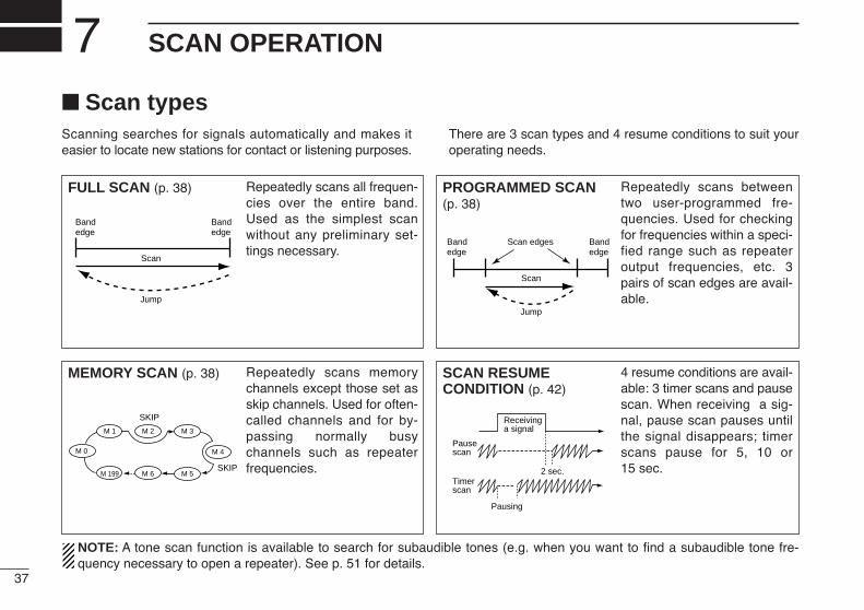
37
SCAN OPERATION7 Scan typesScanning searches for signals automatically and makes iteasier to locate new stations for contact or listening purposes.
There are 3 scan types and 4 resume conditions to suit youroperating needs.
FULL SCAN (p. 38) Repeatedly scans all frequen-cies over the entire band.Used as the simplest scanwithout any preliminary set-tings necessary.
Bandedge
Bandedge
Scan
Jump
PROGRAMMED SCAN(p. 38)
Repeatedly scans betweentwo user-programmed fre-quencies. Used for checkingfor frequencies within a speci-fied range such as repeateroutput frequencies, etc. 3pairs of scan edges are avail-able.
Bandedge
Bandedge
Scan edges
Scan
Jump
MEMORY SCAN (p. 38) Repeatedly scans memorychannels except those set asskip channels. Used for often-called channels and for by-passing normally busychannels such as repeaterfrequencies.
SKIP
SKIP
M 0 M 4
M 1 M 2 M 3
M 5M 199 M 6
SCAN RESUMECONDITION (p. 42)
4 resume conditions are avail-able: 3 timer scans and pausescan. When receiving a sig-nal, pause scan pauses untilthe signal disappears; timerscans pause for 5, 10 or15 sec.
Pausescan
Receivinga signal
Timerscan
Pausing
2 sec.
NOTE: A tone scan function is available to search for subaudible tones (e.g. when you want to find a subaudible tone fre-quency necessary to open a repeater). See p. 51 for details.
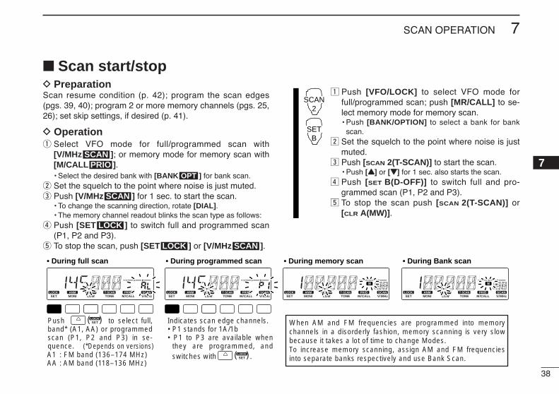
38
7SCAN OPERATION
7
Scan start/stopD PreparationScan resume condition (p. 42); program the scan edges(pgs. 39, 40); program 2 or more memory channels (pgs. 25,26); set skip settings, if desired (p. 41).
D Operationq Select VFO mode for full/programmed scan with
[V/MHz ]; or memory mode for memory scan with[M/CALL ].• Select the desired bank with [BANK ] for bank scan.
w Set the squelch to the point where noise is just muted.e Push [V/MHz ] for 1 sec. to start the scan.
• To change the scanning direction, rotate [DIAL].• The memory channel readout blinks the scan type as follows:
r Push [SET ] to switch full and programmed scan(P1, P2 and P3).
t To stop the scan, push [SET ] or [V/MHz ].
z Push [VFO/LOCK] to select VFO mode forfull/programmed scan; push [MR/CALL] to se-lect memory mode for memory scan.• Push [BANK/OPTION] to select a bank for bank
scan.x Set the squelch to the point where noise is just
muted.c Push [SCAN 2(T-SCAN)] to start the scan.
• Push [YY] or [ZZ] for 1 sec. also starts the scan.v Push [SET B(D-OFF)] to switch full and pro-
grammed scan (P1, P2 and P3).b To stop the scan push [SCAN 2(T-SCAN)] or
[CLR A(MW)].
SCAN2
SETB
SCANLOCK
LOCK
SCAN
OPTPRIO
SCAN
LOCKSET
ANMMONI
DUPLOW
T-SCANTONE
PRIOM/CALL
SCANV/MHz
DIGITAL PRIO AO BUSYMUTENARMIDLOW
LOCKSET
ANMMONI
DUPLOW
T-SCANTONE
PRIOM/CALL
SCANV/MHz
DIGITAL PRIO AO BUSYMUTENARMIDLOW
LOCKSET
ANMMONI
DUPLOW
T-SCANTONE
PRIOM/CALL
SCANV/MHz
DIGITAL PRIO AO BUSYMUTENARMIDLOW
LOCKSET
ANMMONI
DUPLOW
T-SCANTONE
PRIOM/CALL
SCANV/MHz
DIGITAL PRIO AO BUSYMUTENARMIDLOW
• During full scan • During programmed scan • During memory scan • During Bank scan
Indicates scan edge channels.• P1 stands for 1A/1b• P1 to P3 are available when
they are programmed, and switches with .
Push to select full, band* (A1, AA) or programmed scan (P1, P2 and P3) in se-quence.
LOCKSET( )
LOCKSET( )A1 : FM band (136–174 MHz)
AA : AM band (118–136 MHz)
(*Depends on versions)
When AM and FM frequencies are programmed into memory channels in a disorderly fashion, memory scanning is very slow because it takes a lot of time to change Modes.To increase memory scanning, assign AM and FM frequencies into separate banks respectively and use Bank Scan.
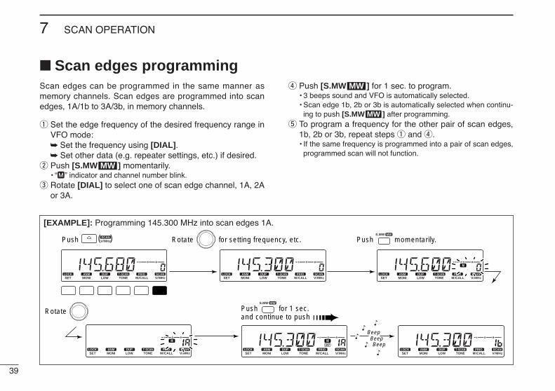
39
7 SCAN OPERATION
Scan edges programmingScan edges can be programmed in the same manner asmemory channels. Scan edges are programmed into scanedges, 1A/1b to 3A/3b, in memory channels.
q Set the edge frequency of the desired frequency range inVFO mode: Set the frequency using [DIAL]. Set other data (e.g. repeater settings, etc.) if desired.
w Push [S.MW ] momentarily.• “M” indicator and channel number blink.
e Rotate [DIAL] to select one of scan edge channel, 1A, 2Aor 3A.
r Push [S.MW ] for 1 sec. to program.• 3 beeps sound and VFO is automatically selected.• Scan edge 1b, 2b or 3b is automatically selected when continu-
ing to push [S.MW ] after programming.t To program a frequency for the other pair of scan edges,
1b, 2b or 3b, repeat steps q and r.• If the same frequency is programmed into a pair of scan edges,
programmed scan will not function.
MW
MW
MW
[EXAMPLE]: Programming 145.300 MHz into scan edges 1A.
LOCKSET
ANMMONI
DUPLOW
T-SCANTONE
PRIOM/CALL
SCANV/MHz
SCANV/MHz
MWS.MW
DIGITAL PRIO AO BUSYMUTENARMIDLOW
LOCKSET
ANMMONI
DUPLOW
T-SCANTONE
PRIOM/CALL
SCANV/MHz
DIGITAL PRIO AO BUSYMUTENARMIDLOW
LOCKSET
ANMMONI
DUPLOW
T-SCANTONE
PRIOM/CALL
SCANV/MHz
DIGITAL PRIO AO BUSYMUTENARMIDLOW
LOCKSET
ANMMONI
DUPLOW
T-SCANTONE
PRIOM/CALL
SCANV/MHz
DIGITAL PRIO AO BUSYMUTENARMIDLOW
LOCKSET
ANMMONI
DUPLOW
T-SCANTONE
PRIOM/CALL
SCANV/MHz
DIGITAL PRIO AO BUSYMUTENARMIDLOW
LOCKSET
ANMMONI
DUPLOW
T-SCANTONE
PRIOM/CALL
SCANV/MHz
DIGITAL PRIO AO BUSYMUTENARMIDLOW
MWS.MW
( )Push Rotate for setting frequency, etc. Push momentarily.
Rotate Push for 1 sec. and continue to push
BeepBeepBeep
“
““
“
“
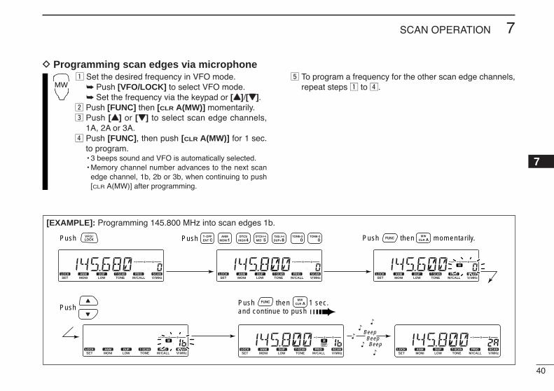
40
7SCAN OPERATION
7
D Programming scan edges via microphonez Set the desired frequency in VFO mode.
Push [VFO/LOCK] to select VFO mode. Set the frequency via the keypad or [YY]/[ZZ].
x Push [FUNC] then [CLR A(MW)] momentarily.c Push [YY] or [ZZ] to select scan edge channels,
1A, 2A or 3A.v Push [FUNC], then push [CLR A(MW)] for 1 sec.
to program.• 3 beeps sound and VFO is automatically selected.• Memory channel number advances to the next scan
edge channel, 1b, 2b or 3b, when continuing to push[CLR A(MW)] after programming.
b To program a frequency for the other scan edge channels,repeat steps z to v.MW
[EXAMPLE]: Programming 145.800 MHz into scan edges 1b.
LOCKSET
ANMMONI
DUPLOW
T-SCANTONE
PRIOM/CALL
SCANV/MHz
DIGITAL PRIO AO BUSYMUTENARMIDLOW
LOCKSET
ANMMONI
DUPLOW
T-SCANTONE
PRIOM/CALL
SCANV/MHz
DIGITAL PRIO AO BUSYMUTENARMIDLOW
LOCKSET
ANMMONI
DUPLOW
T-SCANTONE
PRIOM/CALL
SCANV/MHz
DIGITAL PRIO AO BUSYMUTENARMIDLOW
LOCKSET
ANMMONI
DUPLOW
T-SCANTONE
PRIOM/CALL
SCANV/MHz
DIGITAL PRIO AO BUSYMUTENARMIDLOW
LOCKSET
ANMMONI
DUPLOW
T-SCANTONE
PRIOM/CALL
SCANV/MHz
DIGITAL PRIO AO BUSYMUTENARMIDLOW
LOCKSET
ANMMONI
DUPLOW
T-SCANTONE
PRIOM/CALL
SCANV/MHz
DIGITAL PRIO AO BUSYMUTENARMIDLOW
BeepBeepBeep
“
““
“
“
Push Push then momentarily.
PushPush then 1 sec. and continue to push
Push
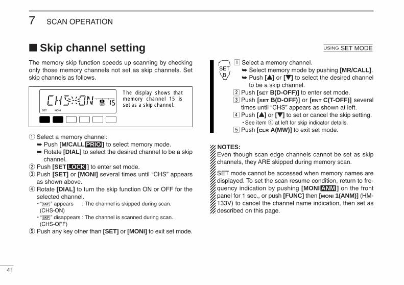
41
7 SCAN OPERATION
Skip channel settingThe memory skip function speeds up scanning by checkingonly those memory channels not set as skip channels. Setskip channels as follows.
q Select a memory channel: Push [M/CALL ] to select memory mode. Rotate [DIAL] to select the desired channel to be a skip
channel.w Push [SET ] to enter set mode.e Push [SET] or [MONI] several times until “CHS” appears
as shown above.r Rotate [DIAL] to turn the skip function ON or OFF for the
selected channel.• “~” appears : The channel is skipped during scan.
(CHS-ON)• “~” disappears : The channel is scanned during scan.
(CHS-OFF)t Push any key other than [SET] or [MONI] to exit set mode.
z Select a memory channel. Select memory mode by pushing [MR/CALL]. Push [YY] or [ZZ] to select the desired channel
to be a skip channel.x Push [SET B(D-OFF)] to enter set mode.c Push [SET B(D-OFF)] or [ENT C(T-OFF)] several
times until “CHS” appears as shown at left.v Push [YY] or [ZZ] to set or cancel the skip setting.
• See item r at left for skip indicator details.b Push [CLR A(MW)] to exit set mode.
NOTES:Even though scan edge channels cannot be set as skipchannels, they ARE skipped during memory scan.
SET mode cannot be accessed when memory names aredisplayed. To set the scan resume condition, return to fre-quency indication by pushing [MONI ] on the frontpanel for 1 sec., or push [FUNC] then [MONI 1(ANM)] (HM-133V) to cancel the channel name indication, then set asdescribed on this page.
ANM
SETB
USING SET MODE
LOCK
PRIO
LOCKSET
ANMMONI
DUPLOW
T-SCANTONE
PRIOM/CALL
SCANV/MHz
DIGITAL PRIO AO BUSYMUTENARMIDLOW
The display shows that memory channel 15 is set as a skip channel.
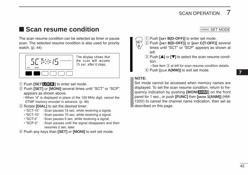
42
7SCAN OPERATION
7
Scan resume conditionThe scan resume condition can be selected as timer or pausescan. The selected resume condition is also used for prioritywatch. (p. 44)
q Push [SET ] to enter set mode.w Push [SET] or [MONI] several times until “SCT” or “SCP”
appears as shown above.• When “d” is displayed in place of the 100 MHz digit, cancel the
DTMF memory encoder in advance. (p. 46)e Rotate [DIAL] to set the desired timer:
• “SCT-15” : Scan pauses 15 sec. while receiving a signal.• “SCT-10” : Scan pauses 10 sec. while receiving a signal.• “SCT-5” : Scan pauses 5 sec. while receiving a signal.• “SCP-2” : Scan pauses until the signal disappears and then
resumes 2 sec. later.r Push any keys than [SET] or [MONI] to exit set mode.
z Push [SET B(D-OFF)] to enter set mode.x Push [SET B(D-OFF)] or [ENT C(T-OFF)] several
times until “SCT” or “SCP” appears as shown atleft.
c Push [YY] or [ZZ] to select the scan resume condi-tion.• See item e at left for scan resume condition details.
v Push [CLR A(MW)] to exit set mode.
NOTE: Set mode cannot be accessed when memory names aredisplayed. To set the scan resume condition, return to fre-quency indication by pushing [MONI ] on the frontpanel for 1 sec., or push [FUNC] then [MONI 1(ANM)] (HM-133V) to cancel the channel name indication, then set asdescribed on this page.
ANM
SETB
USING SET MODE
LOCK
LOCKSET
ANMMONI
DUPLOW
T-SCANTONE
PRIOM/CALL
SCANV/MHz
DIGITAL PRIO AO BUSYMUTENARMIDLOW
The display shows that the scan will resume 15 sec. after it stops.

43
PRIORITY WATCH8 Priority watch typesThe transceiver has 3 priority watch types to suit your needs.You can transmit on the VFO frequency while the prioritywatch operates.
The watch resumes according to the selected scan resumecondition. See previous page for details.
NOTE: If the pocket beep function is activated, the trans-ceiver automatically selects the tone squelch functionwhen priority watch starts.
MEMORY CHANNEL WATCHWhile operating on a VFO fre-quency, priority watch checks fora signal on the selected memorychannel every 5 sec.
MEMORY SCAN WATCHWhile operating on a VFO fre-quency, priority watch checks forsignals on each memory chan-nel in sequence.• The memory skip function is useful
to speed up the scan.
5 sec.
VFOfrequency
50 msec.Memorychannel
5 sec.50 msec.
VFOfrequency
SKIP
Mch 1Mch 2
Mch 3
Mch 199
CALL CHANNEL WATCHWhile operating on a VFO fre-quency, priority watch checks forsignals on the call channel every5 sec.
5 sec.
VFOfrequency
50 msec.Call
channel
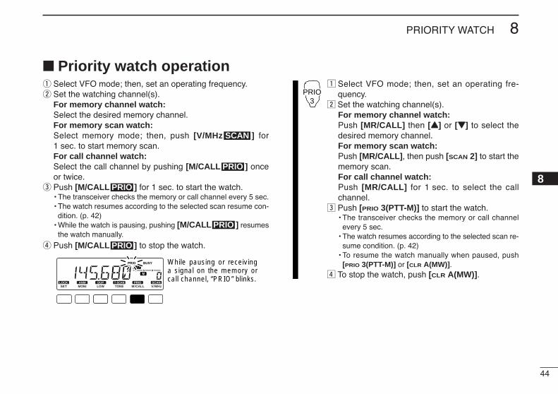
44
8PRIORITY WATCH
8
Priority watch operationq Select VFO mode; then, set an operating frequency.w Set the watching channel(s).
For memory channel watch:Select the desired memory channel.For memory scan watch:Select memory mode; then, push [V/MHz ] for1 sec. to start memory scan.For call channel watch:Select the call channel by pushing [M/CALL ] onceor twice.
e Push [M/CALL ] for 1 sec. to start the watch.• The transceiver checks the memory or call channel every 5 sec.• The watch resumes according to the selected scan resume con-
dition. (p. 42)• While the watch is pausing, pushing [M/CALL ] resumes
the watch manually.
r Push [M/CALL ] to stop the watch.
z Select VFO mode; then, set an operating fre-quency.
x Set the watching channel(s).For memory channel watch:Push [MR/CALL] then [YY] or [ZZ] to select thedesired memory channel.For memory scan watch:Push [MR/CALL], then push [SCAN 2] to start thememory scan.For call channel watch:Push [MR/CALL] for 1 sec. to select the callchannel.
c Push [PRIO 3(PTT-M)] to start the watch.• The transceiver checks the memory or call channel
every 5 sec.• The watch resumes according to the selected scan re-
sume condition. (p. 42)• To resume the watch manually when paused, push
[PRIO 3(PTT-M)] or [CLR A(MW)].v To stop the watch, push [CLR A(MW)].
PRIO3
LOCKSET
ANMMONI
DUPLOW
T-SCANTONE
PRIOM/CALL
SCANV/MHz
DIGITAL PRIO AO BUSYMUTENARMIDLOW
While pausing or receiving a signal on the memory or call channel, “PRIO” blinks.
PRIO
PRIO
PRIO
PRIO
SCAN
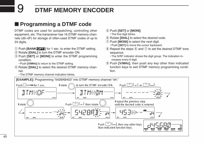
45
DTMF MEMORY ENCODER9 Programming a DTMF codeDTMF codes are used for autopatching, controlling otherequipment, etc. The transceiver has 16 DTMF memory chan-nels (d0–dF) for storage of often-used DTMF codes of up to24 digits.
q Push [BANK ] for 1 sec. to enter the DTMF setting.w Rotate [DIAL] to turn the DTMF encoder ON.e Push [SET] or [MONI] to enter the DTMF programming
condition.• Push [V/MHz] to return to the DTMF setting.
r Rotate [DIAL] to select the desired DTMF memory chan-nel.• The DTMF memory channel indication blinks.
t Push [SET] or [MONI].• The first digit blinks.
y Rotate [DIAL] to select the desired code.u Push [MONI] to select the next digit.
• Push [SET] to move the cursor backward.i Repeat the steps y and u to set the desired DTMF tone
sequence.• The S/RF indicator shows the digit group. The indication in-
creases every 6 digit.o Push [V/MHz], then push any key other than indicated
function keys to exit DTMF memory programming condi-tion.
OPT
[EXAMPLE]: Programming “5428AB453” into DTMF memory channel “d4.”
LOCKSET
ANMMONI
DUPLOW
T-SCANTONE
PRIOM/CALL
SCANV/MHz
DIGITAL PRIO AO BUSYMUTENARMIDLOW
LOCKSET
ANMMONI
DUPLOW
T-SCANTONE
PRIOM/CALL
SCANV/MHz
DIGITAL PRIO AO BUSYMUTENARMIDLOW
LOCKSET
ANMMONI
DUPLOW
T-SCANTONE
PRIOM/CALL
SCANV/MHz
DIGITAL PRIO AO BUSYMUTENARMIDLOW
LOCKSET
ANMMONI
DUPLOW
T-SCANTONE
PRIOM/CALL
SCANV/MHz
DIGITAL PRIO AO BUSYMUTENARMIDLOW
LOCKSET
ANMMONI
DUPLOW
T-SCANTONE
PRIOM/CALL
SCANV/MHz
DIGITAL PRIO AO BUSYMUTENARMIDLOW
LOCKSET
ANMMONI
DUPLOW
T-SCANTONE
PRIOM/CALL
SCANV/MHz
DIGITAL PRIO AO BUSYMUTENARMIDLOW
LOCKSET
ANMMONI
DUPLOW
T-SCANTONE
PRIOM/CALL
SCANV/MHz
DIGITAL PRIO AO BUSYMUTENARMIDLOW
OPTBANK SET( ) MONI( )Push or .
V/MHz( )Push , then any other keys than indicated function keys.
SET( )Push then rotate .Repeat the previous step until the desired code is entered.
Rotate to turn the DTMF encoder ON.
Rotate .
Push for 1 sec.

46
9DTMF MEMORY ENCODER
9
Transmitting a DTMF codeD Automatic transmission (DTMF memory)
z Push [FUNC] then [LOW 6(DTMF)] to turn theDTMF memory encoder ON.• “d” appears in place of the 100 MHz digit.
x Push [BANK/OPTION] for 1 sec. then [SET B(D-OFF)] to enter the DTMF memory pro-gramming condition.
c Push [YY] or [ZZ] to select the desired channel.v Push [PTT] to transmit the selected memory.
• Exit the programming condition automatically.• Each push of [PTT] transmits the DTMF code.
b Push [FUNC] then [SET B(D-OFF)] to cancel theDTMF memory encoder.• When the DTMF encoder is turned ON continuously,
each push of the PTT transmits the previously se-lected DTMF code.
D Transmitting a DTMF memory directlyz Push [FUNC] then [LOW 6(DTMF)] to turn the
DTMF memory encoder ON.• “d” appears in place of the 100 MHz digit.
x Push [DTMF-S] to turn the DTMF memory di-rect selection ON.• The function indicator (microphone) lights green.
c Push the desired DTMF channel number.• “0” to “9” are available for channel numbers.• The selected DTMF code is automatically transmit-
ted without pushing PTT.
Transmitting a DTMF memory directly— continuedNOTE: When no DTMF code programmed chan-nel number is pushed, it transmits previouslytransmitted DTMF memory code.
v Push [DTMF-S] again to deactivate the DTMFmemory direct selection.
b Push [FUNC] then [SET B(D-OFF)] to cancelthe DTMF memory encoder.
D Manual transmissionz Deactivate the DTMF memory encoder by
pushing [FUNC] then [SET B(D-OFF)].x Push [DTMF-S] to turn the DTMF direct selec-
tion ON.• The function indicator (microphone) lights green.
c Push one of “A” to “F” keys momentarily, thenpush the desired DTMF keys, 0–9 and A to F.• A: [CLR A(MW)] B: [SET B(D-OFF)],
C: [ENT C(T-OFF)] D: [SQLYY D(MUTE)], E: [MM(TONE-1)] F: [SQLZZ #(16KEY-L)]
• Automatically transmits without pushing PTT.• The first code, one of “A” to “F,” is not transmitted.
DTMF code transmission starts from the 2nd code.v Push [DTMF-S] again to deactivate the DTMF
direct selection.
DTMF-S
DTMF-S
DTMF-S
DTMF
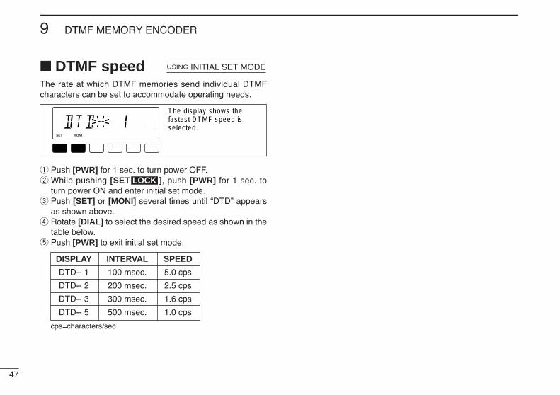
47
9 DTMF MEMORY ENCODER
DTMF speedThe rate at which DTMF memories send individual DTMFcharacters can be set to accommodate operating needs.
q Push [PWR] for 1 sec. to turn power OFF.w While pushing [SET ], push [PWR] for 1 sec. to
turn power ON and enter initial set mode.e Push [SET] or [MONI] several times until “DTD” appears
as shown above.r Rotate [DIAL] to select the desired speed as shown in the
table below.t Push [PWR] to exit initial set mode.
cps=characters/sec
LOCK
LOCKSET
ANMMONI
DUPLOW
T-SCANTONE
PRIOM/CALL
SCANV/MHz
DIGITAL PRIO AO BUSYMUTENARMIDLOW
The display shows the fastest DTMF speed is selected.
USING INITIAL SET MODE
DISPLAY INTERVAL SPEED
DTD-- 1 100 msec. 5.0 cps
DTD-- 2 200 msec. 2.5 cps
DTD-- 3 300 msec. 1.6 cps
DTD-- 5 500 msec. 1.0 cps
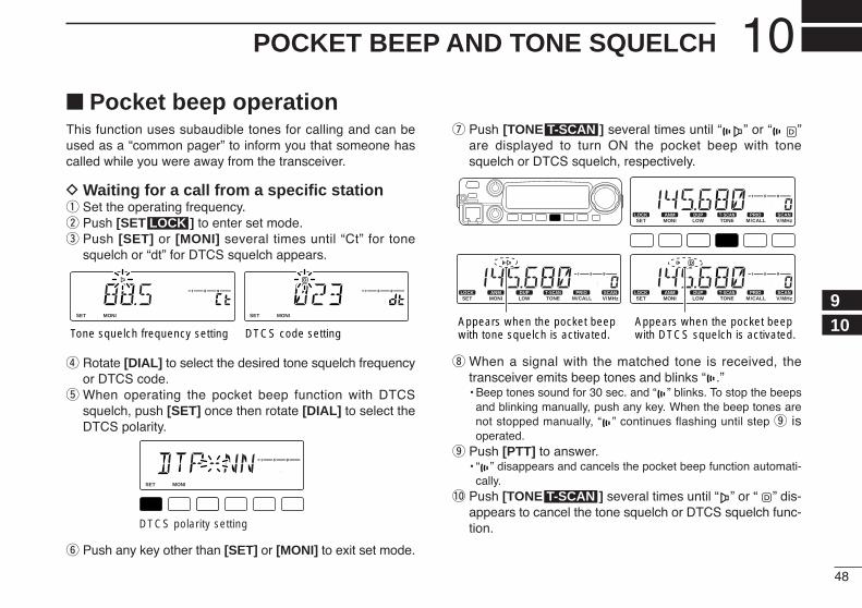
48
10POCKET BEEP AND TONE SQUELCH
910
Pocket beep operationThis function uses subaudible tones for calling and can beused as a “common pager” to inform you that someone hascalled while you were away from the transceiver.
D Waiting for a call from a specific stationq Set the operating frequency.w Push [SET ] to enter set mode.e Push [SET] or [MONI] several times until “Ct” for tone
squelch or “dt” for DTCS squelch appears.
r Rotate [DIAL] to select the desired tone squelch frequencyor DTCS code.
t When operating the pocket beep function with DTCSsquelch, push [SET] once then rotate [DIAL] to select theDTCS polarity.
y Push any key other than [SET] or [MONI] to exit set mode.
u Push [TONE ] several times until “ ” or “ ”are displayed to turn ON the pocket beep with tonesquelch or DTCS squelch, respectively.
i When a signal with the matched tone is received, thetransceiver emits beep tones and blinks “ .”• Beep tones sound for 30 sec. and “ ” blinks. To stop the beeps
and blinking manually, push any key. When the beep tones arenot stopped manually, “ ” continues flashing until step o is operated.
o Push [PTT] to answer.• “ ” disappears and cancels the pocket beep function automati-
cally.!0 Push [TONE ] several times until “ ” or “ ” dis-
appears to cancel the tone squelch or DTCS squelch func-tion.
T-SCAN
LOCKSET
ANMMONI
DUPLOW
T-SCANTONE
PRIOM/CALL
SCANV/MHz
DIGITAL PRIO AO BUSYMUTENARMIDLOW
LOCKSET
ANMMONI
DUPLOW
T-SCANTONE
PRIOM/CALL
SCANV/MHz
DIGITAL PRIO AO BUSYMUTENARMIDLOW
LOCKSET
ANMMONI
DUPLOW
T-SCANTONE
PRIOM/CALL
SCANV/MHz
DIGITAL PRIO AO BUSYMUTENARMIDLOW
Appears when the pocket beep with tone squelch is activated.
Appears when the pocket beepwith DTCS squelch is activated.
T-SCAN
LOCKSET
ANMMONI
DUPLOW
T-SCANTONE
PRIOM/CALL
SCANV/MHz
DIGITAL PRIO AO BUSYMUTENARMIDLOW
DTCS polarity setting
LOCKSET
ANMMONI
DUPLOW
T-SCANTONE
PRIOM/CALL
SCANV/MHz
DIGITAL PRIO AO BUSYMUTENARMIDLOW
LOCKSET
ANMMONI
DUPLOW
T-SCANTONE
PRIOM/CALL
SCANV/MHz
DIGITAL PRIO AO BUSYMUTENARMIDLOW
Tone squelch frequency setting DTCS code setting
LOCK

49
10 POCKET BEEP AND TONE SQUELCH
Waiting for a call from a specific station—continued
z Set the operating frequency.x Program the CTCSS tone frequency or DTCS
code in set mode. Push [SET B(D-OFF)] to enter set mode. Push [SET B(D-OFF)] or [ENT C(T-OFF)]
several times until “Ct” for tone squelch or“dt” for DTCS squelch appears.• “ ” blinks when tone squelch (“Ct”), or “ ”
blinks when DTCS squelch (“dt”) is selected. Push [YY]/[ZZ] to select the desired tone
frequency or DTCS code. Push [SET B(D-OFF)] to select “DTP” then
push [YY]/[ZZ] to select the DTCS polarity. Push [CLR A(MW)] to exit set mode.
c Push [FUNC] then push [DUP+ 8(TSQLSS)]or [MID 5(DTCSSS)] to turn ON the pocketbeep with tone squelch or DTCS squelch, re-spectively.
v When a signal with the matched tone is re-ceived, the transceiver emits beep tones for30 sec. and blinks “ .”
b Push [PTT] to answer or push [CLR A(MW)]to stop the beeps and flashing.• “ ” disappears and cancels the pocket beep func-
tion automatically.n To cancel the tone squelch or DTCS squelch
function, push [FUNC] then [ENT C(T-OFF)]. • “ ” or “ ” disappears
D Available tone frequency list
NOTE: The transceiver has 50 tone frequencies and con-sequently their spacing is narrow compared to units having38 tones. Therefore, some tone frequencies may receiveinterference from adjacent tone frequencies.To prevent interference from adjacent tone frequencies,using the frequencies as in the following table, is recom-mended.
D Calling a waiting station using pocket beepA subaudible tone matched with the station’s CTCSS tone fre-quency or 3-digit DTCS code with polarity is necessary. Usethe tone squelch on the next page or a subaudible tone en-coder (pgs. 19, 50)
67.069.371.974.4
88.591.594.897.4
114.8118.8123.0127.3
151.4156.7162.2167.9
203.5210.7218.1225.7
77.079.782.585.4
100.0103.5107.2110.9
131.8136.5141.3146.2
173.8179.9186.2192.8
233.6241.8250.3
• Recommended tone frequencies
67.069.371.974.477.0
79.782.585.488.591.5
94.897.4
100.0103.5107.2
110.9114.8118.8123.0127.3
131.8136.5141.3146.2151.4
156.7159.8162.2165.5167.9
171.3173.8177.3179.9183.5
186.2189.9192.8196.6199.5
203.5206.5210.7218.1225.7
229.1233.6241.8250.3254.1
TSQLS
DTCSS
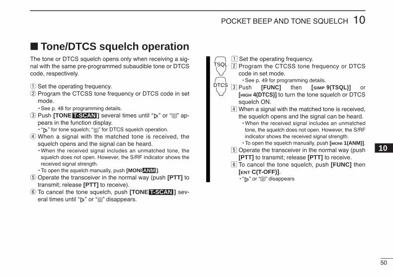
50
10POCKET BEEP AND TONE SQUELCH
10
Tone/DTCS squelch operationThe tone or DTCS squelch opens only when receiving a sig-nal with the same pre-programmed subaudible tone or DTCScode, respectively.
q Set the operating frequency.w Program the CTCSS tone frequency or DTCS code in set
mode.• See p. 48 for programming details.
e Push [TONE ] several times until “ ” or “ ” ap-pears in the function display.• “ ” for tone squelch; “ ” for DTCS squelch operation.
r When a signal with the matched tone is received, thesquelch opens and the signal can be heard.• When the received signal includes an unmatched tone, the
squelch does not open. However, the S/RF indicator shows thereceived signal strength.
• To open the squelch manually, push [MONI ].t Operate the transceiver in the normal way (push [PTT] to
transmit; release [PTT] to receive).y To cancel the tone squelch, push [TONE ] sev-
eral times until “ ” or “ ” disappears.
z Set the operating frequency.x Program the CTCSS tone frequency or DTCS
code in set mode.• See p. 49 for programming details.
c Push [FUNC] then [SIMP 9(TSQL)] or[HIGH 4(DTCS)] to turn the tone squelch or DTCSsquelch ON.
v When a signal with the matched tone is received,the squelch opens and the signal can be heard.
• When the received signal includes an unmatchedtone, the squelch does not open. However, the S/RFindicator shows the received signal strength.
• To open the squelch manually, push [MONI 1(ANM)].b Operate the transceiver in the normal way (push
[PTT] to transmit; release [PTT] to receive.n To cancel the tone squelch, push [FUNC] then
[ENT C(T-OFF)].• “ ” or “ ” disappears
TSQL
DTCS
T-SCAN
ANM
T-SCAN

51
10 POCKET BEEP AND TONE SQUELCH
Tone scanBy monitoring a signal that is being operated with pocketbeep, tone or DTCS squelch function, you can determine thetone frequency or DTCS code necessary to open a squelch.
q Set the channel to be checked for a tone frequency orcode.
w Push [TONE ] several times to select the tonecondition or type to be scanned.• One of “ ,” “ ” or “ ” appears
e Push [TONE ] for 1 sec. to start the tone scan.• To change the scanning direction, rotate [DIAL].
r When the CTCSS tone frequency or 3-digit DTCS code ismatched, the squelch opens and the tone frequency istemporarily programmed into the selected condition suchas memory or call channel.• The tone scan pauses when a CTCSS tone frequency or 3-digit
DTCS code is detected.• The decoded CTCSS tone frequency or 3-digit DTCS code is
used for the tone encoder or tone encoder/decoder dependingon the selected tone condition or type in step w. - No indication : Cannot be used for operation.- “ ” : CTCSS tone encoder- “ ” : CTCSS tone encoder/decoder- “ ” : DTCS tone encoder/decoder
t Push [V/MHz ] to stop the scan.
z Set the channel to be checked for a tone fre-quency.
x Selects the tone condition or type to bescanned.• Push [FUNC] then push; [DUP– 7(TONE)] for re-
peater tone; [SIMP 9(TSQL)] for tone squelch;[HIGH 4(DTCS)] for DTCS squelch.
c Push [FUNC] then [SCAN 2(T-SCAN)] to startthe tone scan.
v When the tone frequency is matched, thesquelch opens and the tone frequency is pro-grammed into the selected mode such asmemory or call channel.
b Push [CLR A(MW)] to stop the scan.
T-SCAN
SCAN
LOCKSET
ANMMONI
DUPLOW
T-SCANTONE
PRIOM/CALL
SCANV/MHz
DIGITAL PRIO AO BUSYMUTENARMIDLOW
LOCKSET
ANMMONI
DUPLOW
T-SCANTONE
PRIOM/CALL
SCANV/MHz
DIGITAL PRIO AO BUSYMUTENARMIDLOW
LOCKSET
ANMMONI
DUPLOW
T-SCANTONE
PRIOM/CALL
SCANV/MHz
DIGITAL PRIO AO BUSYMUTENARMIDLOW
During CTCSS tone scan During DTCS code scan
T-SCAN
T-SCAN
NOTE: The decoded tone frequency is programmed tem-porarily when a memory or call channel is selected. How-ever, this will be cleared when the memory/call channel isre-selected.

52
11PAGER/CODE SQUELCH
1011
Pager functionThis function uses DTMF codes for paging and can be usedas a “message pager” to inform you of a caller’s identificationeven when you leave the transceiver temporarily unattended.
Code programmingDD Before programmingThe pager and code squelch functions require ID codes and agroup code. These codes are 3-digit DTMF codes and mustbe written into the code channels before operation.
q Decide the ID code of each transceiver and a group codefor your group.
w Decide whether you want to return to normal operation orcode squelch operation after a connection is made.
e Program the ID code, group code and transmit codes(other station’s codes) as below.
DD Code channel assignment
*Channel CP automatically memorizes an ID code when receiving apager call. The contents in channel CP cannot be changed manually.
Pager selective code (push [PTT])
Beep BeepBeep
Answer back (manual)
Beep Beep
Beep
Set both transceivers toeither code squelch or non-coded operation
Communication
ID OR CODE CHANNEL “RECEIVE ACCEPT” OR GROUP CODE NUMBER “RECEIVE INHIBIT”
Your ID code 0 “Receive accept” only
Other parties’1–6
“Receive inhibit” should be ID code programmed in each channel.
Group code One of 1–6“Receive accept” must be
programmed.
Memory space* P “Receive inhibit” only.
Required Optional UT-108
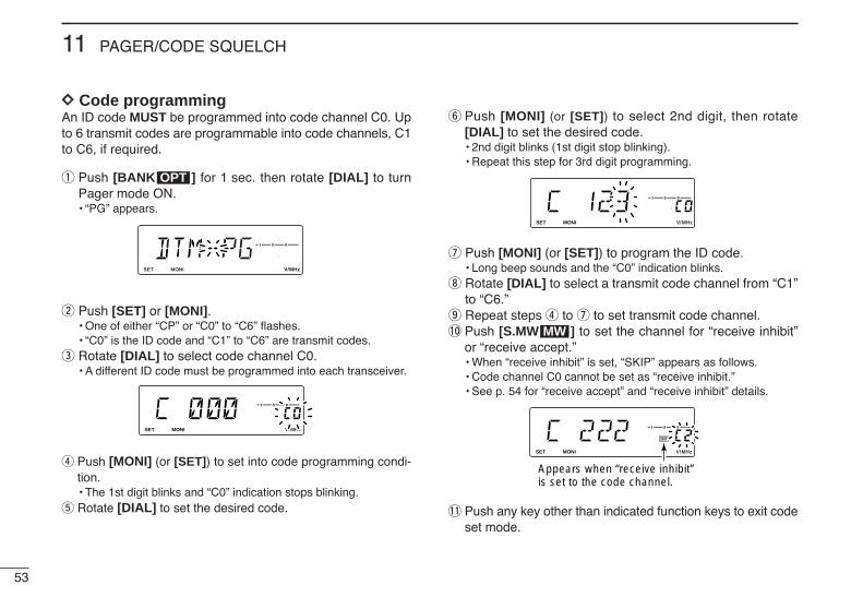
53
11 PAGER/CODE SQUELCH
DD Code programmingAn ID code MUST be programmed into code channel C0. Upto 6 transmit codes are programmable into code channels, C1to C6, if required.
q Push [BANK ] for 1 sec. then rotate [DIAL] to turnPager mode ON.• “PG” appears.
w Push [SET] or [MONI].• One of either “CP” or “C0” to “C6” flashes.• “C0” is the ID code and “C1” to “C6” are transmit codes.
e Rotate [DIAL] to select code channel C0.• A different ID code must be programmed into each transceiver.
r Push [MONI] (or [SET]) to set into code programming condi-tion.• The 1st digit blinks and “C0” indication stops blinking.
t Rotate [DIAL] to set the desired code.
y Push [MONI] (or [SET]) to select 2nd digit, then rotate[DIAL] to set the desired code.• 2nd digit blinks (1st digit stop blinking).• Repeat this step for 3rd digit programming.
u Push [MONI] (or [SET]) to program the ID code.• Long beep sounds and the “C0” indication blinks.
i Rotate [DIAL] to select a transmit code channel from “C1”to “C6.”
o Repeat steps r to u to set transmit code channel.!0 Push [S.MW ] to set the channel for “receive inhibit”
or “receive accept.”• When “receive inhibit” is set, “SKIP” appears as follows.• Code channel C0 cannot be set as “receive inhibit.”• See p. 54 for “receive accept” and “receive inhibit” details.
!1 Push any key other than indicated function keys to exit codeset mode.
LOCKSET
ANMMONI
DUPLOW
T-SCANTONE
PRIOM/CALL
SCANV/MHz
DIGITAL PRIO AO BUSYMUTENARMIDLOW
Appears when “receive inhibit”is set to the code channel.
MW
LOCKSET
ANMMONI
DUPLOW
T-SCANTONE
PRIOM/CALL
SCANV/MHz
DIGITAL PRIO AO BUSYMUTENARMIDLOW
LOCKSET
ANMMONI
DUPLOW
T-SCANTONE
PRIOM/CALL
SCANV/MHz
DIGITAL PRIO AO BUSYMUTENARMIDLOW
LOCKSET
ANMMONI
DUPLOW
T-SCANTONE
PRIOM/CALL
SCANV/MHz
DIGITAL PRIO AO BUSYMUTENARMIDLOW
OPT
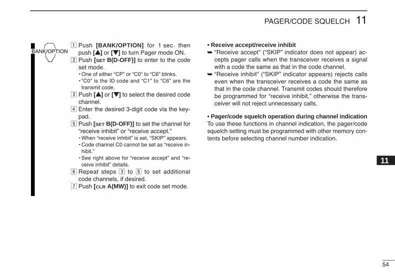
54
11PAGER/CODE SQUELCH
11
z Push [BANK/OPTION] for 1 sec. thenpush [YY] or [ZZ] to turn Pager mode ON.
x Push [SET B(D-OFF)] to enter to the codeset mode.• One of either “CP” or “C0” to “C6” blinks.• “C0” is the ID code and “C1” to “C6” are the
transmit code.c Push [YY] or [ZZ] to select the desired code
channel.v Enter the desired 3-digit code via the key-
pad.b Push [SET B(D-OFF)] to set the channel for
“receive inhibit” or “receive accept.”• When “receive inhibit” is set, “SKIP” appears.• Code channel C0 cannot be set as “receive in-
hibit.”• See right above for “receive accept” and “re-
ceive inhibit” details.n Repeat steps c to b to set additional
code channels, if desired.m Push [CLR A(MW)] to exit code set mode.
• Receive accept/receive inhibit “Receive accept” (“SKIP” indicator does not appear) ac-
cepts pager calls when the transceiver receives a signalwith a code the same as that in the code channel.
“Receive inhibit” (“SKIP” indicator appears) rejects callseven when the transceiver receives a code the same asthat in the code channel. Transmit codes should thereforebe programmed for “receive inhibit,” otherwise the trans-ceiver will not reject unnecessary calls.
• Pager/code squelch operation during channel indicationTo use these functions in channel indication, the pager/codesquelch setting must be programmed with other memory con-tents before selecting channel number indication.
BANK/OPTION
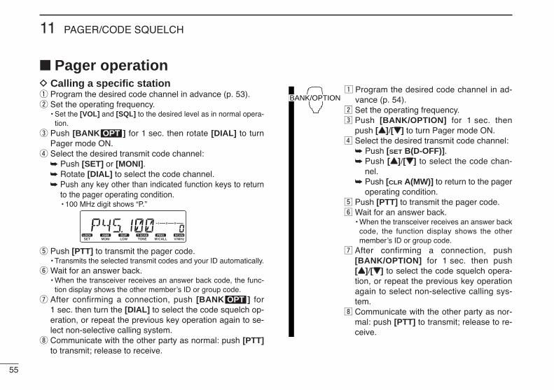
55
11 PAGER/CODE SQUELCH
Pager operationD Calling a specific stationq Program the desired code channel in advance (p. 53).w Set the operating frequency.
• Set the [VOL] and [SQL] to the desired level as in normal opera-tion.
e Push [BANK ] for 1 sec. then rotate [DIAL] to turnPager mode ON.
r Select the desired transmit code channel: Push [SET] or [MONI]. Rotate [DIAL] to select the code channel. Push any key other than indicated function keys to return
to the pager operating condition.• 100 MHz digit shows “P.”
t Push [PTT] to transmit the pager code.• Transmits the selected transmit codes and your ID automatically.
y Wait for an answer back.• When the transceiver receives an answer back code, the func-
tion display shows the other member’s ID or group code.u After confirming a connection, push [BANK ] for
1 sec. then turn the [DIAL] to select the code squelch op-eration, or repeat the previous key operation again to se-lect non-selective calling system.
i Communicate with the other party as normal: push [PTT]to transmit; release to receive.
z Program the desired code channel in ad-vance (p. 54).
x Set the operating frequency.c Push [BANK/OPTION] for 1 sec. then
push [YY]/[ZZ] to turn Pager mode ON.v Select the desired transmit code channel:
Push [SET B(D-OFF)]. Push [YY]/[ZZ] to select the code chan-
nel. Push [CLR A(MW)] to return to the pager
operating condition.b Push [PTT] to transmit the pager code.n Wait for an answer back.
• When the transceiver receives an answer backcode, the function display shows the othermember’s ID or group code.
m After confirming a connection, push[BANK/OPTION] for 1 sec. then push[YY]/[ZZ] to select the code squelch opera-tion, or repeat the previous key operationagain to select non-selective calling sys-tem.
, Communicate with the other party as nor-mal: push [PTT] to transmit; release to re-ceive.
BANK/OPTION
OPT
LOCKSET
ANMMONI
DUPLOW
T-SCANTONE
PRIOM/CALL
SCANV/MHz
DIGITAL PRIO AO BUSYMUTENARMIDLOW
OPT
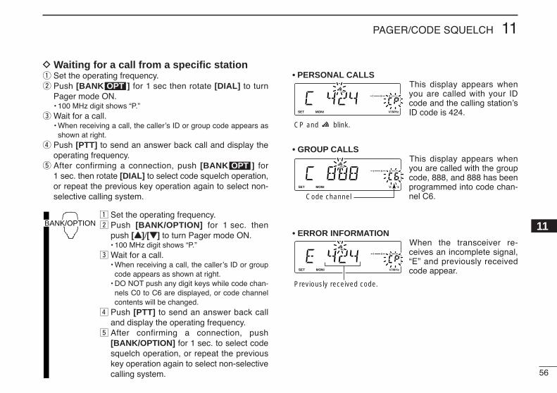
56
11PAGER/CODE SQUELCH
11
D Waiting for a call from a specific stationq Set the operating frequency.w Push [BANK ] for 1 sec then rotate [DIAL] to turn
Pager mode ON.• 100 MHz digit shows “P.”
e Wait for a call.• When receiving a call, the caller’s ID or group code appears as
shown at right.r Push [PTT] to send an answer back call and display the
operating frequency.t After confirming a connection, push [BANK ] for
1 sec. then rotate [DIAL] to select code squelch operation,or repeat the previous key operation again to select non-selective calling system.
z Set the operating frequency.x Push [BANK/OPTION] for 1 sec. then
push [YY]/[ZZ] to turn Pager mode ON.• 100 MHz digit shows “P.”
c Wait for a call.• When receiving a call, the caller’s ID or group
code appears as shown at right.• DO NOT push any digit keys while code chan-
nels C0 to C6 are displayed, or code channelcontents will be changed.
v Push [PTT] to send an answer back calland display the operating frequency.
b After confirming a connection, push[BANK/OPTION] for 1 sec. to select codesquelch operation, or repeat the previouskey operation again to select non-selectivecalling system.
• PERSONAL CALLSThis display appears whenyou are called with your IDcode and the calling station’sID code is 424.
• GROUP CALLSThis display appears whenyou are called with the groupcode, 888, and 888 has beenprogrammed into code chan-nel C6.
• ERROR INFORMATIONWhen the transceiver re-ceives an incomplete signal,“E” and previously receivedcode appear.
LOCKSET
ANMMONI
DUPLOW
T-SCANTONE
PRIOM/CALL
SCANV/MHz
DIGITAL PRIO AO BUSYMUTENARMIDLOW
Previously received code.
LOCKSET
ANMMONI
DUPLOW
T-SCANTONE
PRIOM/CALL
SCANV/MHz
DIGITAL PRIO AO BUSYMUTENARMIDLOW
Code channel
LOCKSET
ANMMONI
DUPLOW
T-SCANTONE
PRIOM/CALL
SCANV/MHz
DIGITAL PRIO AO BUSYMUTENARMIDLOW
CP and blink.
BANK/OPTION
OPT
OPT

57
11 PAGER/CODE SQUELCH
Code squelchCode squelch provides communications with quiet standbysince you will only receive calls from stations which knowyour ID or group code. Each push of [PTT] sends a 3-digitcode in order to open the receiving station’s code squelchprior to voice transmission.
q Set the operating frequency.• Set the AF and squelch to the desired level as in normal opera-
tion.w Push [BANK ] for 1 sec. then rotate [DIAL] to select
code squelch mode.• “CS” appears.
e Select the desired transmit code channel: Push [SET] or [MONI]. Rotate [DIAL] to select the code channel. Push any other keys than indicated function keys to exit
code set mode.• 100 MHz digit shows “C.”
r Operate the transceiver in the normal way (push [PTT] totransmit; release [PTT] to receive).
t To cancel the code squelch, push [BANK ] for 1 sec.then rotate [DIAL].• 100 MHz digit shows “1” when the function is cancelled.
z Set the operating frequency.x Push [BANK/OPTION] for 1 sec. then
push [YY]/[ZZ] to select code squelch mode.• “CS” appears.
c Select the desired transmit code channel: Push [SET] or [MONI]. Push [YY]/[ZZ]. Push [CLR A(MW)] to return to previous
condition.v Communicate with the other party as nor-
mal: push [PTT] to transmit; release to re-ceive.
b To cancel the code squelch, push[BANK/OPTION] for 1 sec then rotate[DIAL].
BANK/OPTION
OPT
LOCKSET
ANMMONI
DUPLOW
T-SCANTONE
PRIOM/CALL
SCANV/MHz
DIGITAL PRIO AO BUSYMUTENARMIDLOW
OPT
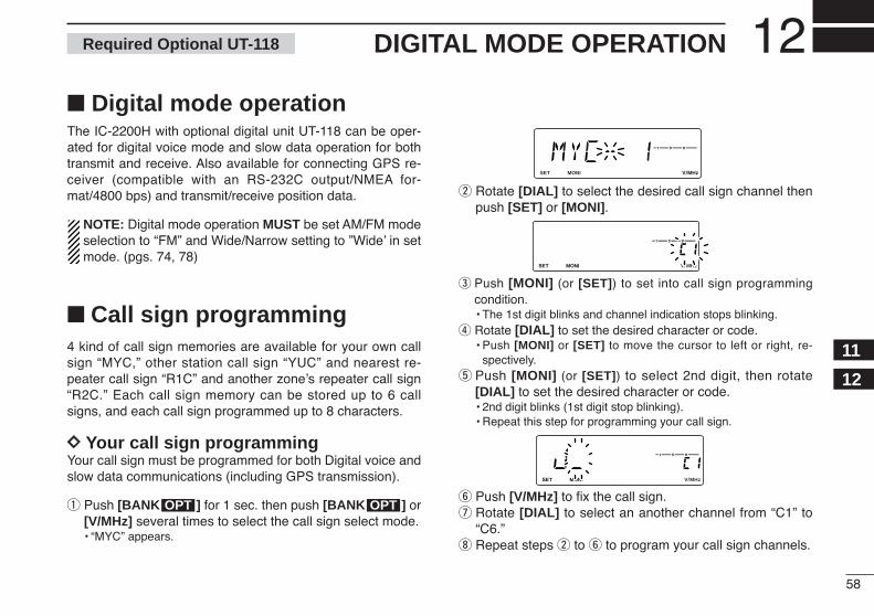
58
12DIGITAL MODE OPERATION
12
11
Digital mode operationThe IC-2200H with optional digital unit UT-118 can be oper-ated for digital voice mode and slow data operation for bothtransmit and receive. Also available for connecting GPS re-ceiver (compatible with an RS-232C output/NMEA for-mat/4800 bps) and transmit/receive position data.
NOTE: Digital mode operation MUST be set AM/FM modeselection to “FM” and Wide/Narrow setting to ”Wide’ in setmode. (pgs. 74, 78)
Call sign programming4 kind of call sign memories are available for your own callsign “MYC,” other station call sign “YUC” and nearest re-peater call sign “R1C” and another zone’s repeater call sign“R2C.” Each call sign memory can be stored up to 6 callsigns, and each call sign programmed up to 8 characters.
DD Your call sign programmingYour call sign must be programmed for both Digital voice andslow data communications (including GPS transmission).
q Push [BANK ] for 1 sec. then push [BANK ] or[V/MHz] several times to select the call sign select mode.• “MYC” appears.
w Rotate [DIAL] to select the desired call sign channel thenpush [SET] or [MONI].
e Push [MONI] (or [SET]) to set into call sign programmingcondition.• The 1st digit blinks and channel indication stops blinking.
r Rotate [DIAL] to set the desired character or code.• Push [MONI] or [SET] to move the cursor to left or right, re-
spectively.t Push [MONI] (or [SET]) to select 2nd digit, then rotate
[DIAL] to set the desired character or code.• 2nd digit blinks (1st digit stop blinking).• Repeat this step for programming your call sign.
y Push [V/MHz] to fix the call sign.u Rotate [DIAL] to select an another channel from “C1” to
“C6.”i Repeat steps w to y to program your call sign channels.
LOCKSET
ANMMONI
DUPLOW
T-SCANTONE
PRIOM/CALL
SCANV/MHz
DIGITAL PRIO AO BUSYMUTENARMIDLOW
LOCKSET
ANMMONI
DUPLOW
T-SCANTONE
PRIOM/CALL
SCANV/MHz
DIGITAL PRIO AO BUSYMUTENARMIDLOW
LOCKSET
ANMMONI
DUPLOW
T-SCANTONE
PRIOM/CALL
SCANV/MHz
DIGITAL PRIO AO BUSYMUTENARMIDLOW
OPTOPT
Required Optional UT-118
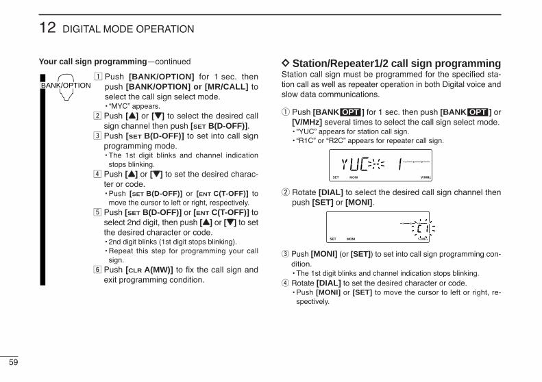
59
12 DIGITAL MODE OPERATION
Your call sign programming—continued
z Push [BANK/OPTION] for 1 sec. thenpush [BANK/OPTION] or [MR/CALL] toselect the call sign select mode.• “MYC” appears.
x Push [YY] or [ZZ] to select the desired callsign channel then push [SET B(D-OFF)].
c Push [SET B(D-OFF)] to set into call signprogramming mode.• The 1st digit blinks and channel indication
stops blinking.v Push [YY] or [ZZ] to set the desired charac-
ter or code.• Push [SET B(D-OFF)] or [ENT C(T-OFF)] to
move the cursor to left or right, respectively.b Push [SET B(D-OFF)] or [ENT C(T-OFF)] to
select 2nd digit, then push [YY] or [ZZ] to setthe desired character or code.• 2nd digit blinks (1st digit stops blinking).• Repeat this step for programming your call
sign.n Push [CLR A(MW)] to fix the call sign and
exit programming condition.
DD Station/Repeater1/2 call sign programming Station call sign must be programmed for the specified sta-tion call as well as repeater operation in both Digital voice andslow data communications.
q Push [BANK ] for 1 sec. then push [BANK ] or[V/MHz] several times to select the call sign select mode.• “YUC” appears for station call sign.• “R1C” or “R2C” appears for repeater call sign.
w Rotate [DIAL] to select the desired call sign channel thenpush [SET] or [MONI].
e Push [MONI] (or [SET]) to set into call sign programming con-dition.• The 1st digit blinks and channel indication stops blinking.
r Rotate [DIAL] to set the desired character or code.• Push [MONI] or [SET] to move the cursor to left or right, re-
spectively.
LOCKSET
ANMMONI
DUPLOW
T-SCANTONE
PRIOM/CALL
SCANV/MHz
DIGITAL PRIO AO BUSYMUTENARMIDLOW
LOCKSET
ANMMONI
DUPLOW
T-SCANTONE
PRIOM/CALL
SCANV/MHz
DIGITAL PRIO AO BUSYMUTENARMIDLOW
OPTOPT
BANK/OPTION
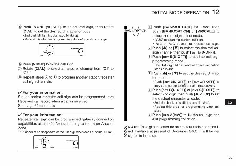
60
12DIGITAL MODE OPERATION
12
t Push [MONI] (or [SET]) to select 2nd digit, then rotate[DIAL] to set the desired character or code.• 2nd digit blinks (1st digit stop blinking).• Repeat this step for programming station/repeater call sign.
y Push [V/MHz] to fix the call sign.u Rotate [DIAL] to select an another channel from “C1” to
“C6.”i Repeat steps w to y to program another station/repeater
call sign channels.
For your information:Station and/or repeater call sign can be programmed fromReceived call record when a call is received.See page 64 for details.
For your information:Repeater call sign can be programmed gateway connectioncapabilities at step r for connecting to the other Area orZone.• “G” appears or disappears at the 8th digit when each pushing [LOW].
z Push [BANK/OPTION] for 1 sec. thenpush [BANK/OPTION] or [MR/CALL] toselect the call sign select mode.• “YUC” appears for station call sign.• “R1C” or “R2C” appears for repeater call sign.
x Push [YY] or [ZZ] to select the desired callsign channel then push [SET B(D-OFF)].
c Push [SET B(D-OFF)] to set into call signprogramming mode.• The 1st digit blinks and channel indication
stops blinking.v Push [YY] or [ZZ] to set the desired charac-
ter or code.• Push [SET B(D-OFF)] or [ENT C(T-OFF)] to
move the cursor to left or right, respectively.b Push [SET B(D-OFF)] or [ENT C(T-OFF)] to
select 2nd digit, then push [YY] or [ZZ] to setthe desired character or code.• 2nd digit blinks (1st digit stops blinking).• Repeat this step for programming your call
sign.n Push [CLR A(MW)] to fix the call sign and
exit programming condition.
NOTE: The digital repeater for an amateur radio operation isnot available at present of December 2003. It will be de-signed in the future.
BANK/OPTION
LOCKSET
ANMMONI
DUPLOW
T-SCANTONE
PRIOM/CALL
SCANV/MHz
DIGITAL PRIO AO BUSYMUTENARMIDLOW
LOCKSET
ANMMONI
DUPLOW
T-SCANTONE
PRIOM/CALL
SCANV/MHz
DIGITAL PRIO AO BUSYMUTENARMIDLOW
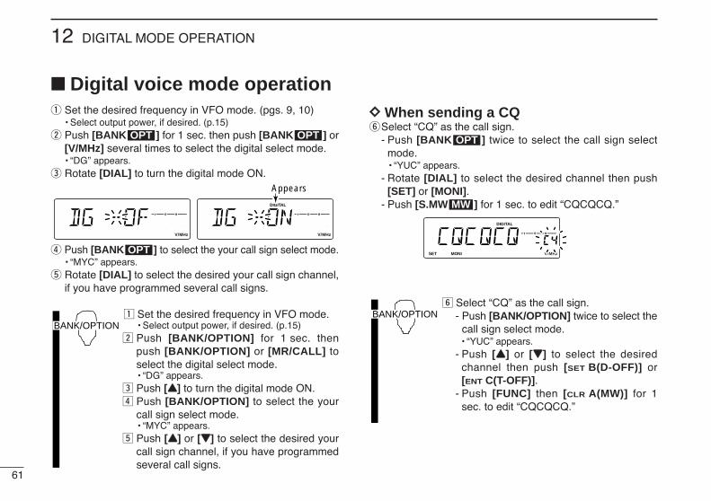
61
12 DIGITAL MODE OPERATION
Digital voice mode operationq Set the desired frequency in VFO mode. (pgs. 9, 10)
• Select output power, if desired. (p.15)w Push [BANK ] for 1 sec. then push [BANK ] or
[V/MHz] several times to select the digital select mode.• “DG” appears.
e Rotate [DIAL] to turn the digital mode ON.
r Push [BANK ] to select the your call sign select mode.• “MYC” appears.
t Rotate [DIAL] to select the desired your call sign channel,if you have programmed several call signs.
z Set the desired frequency in VFO mode.• Select output power, if desired. (p.15)
x Push [BANK/OPTION] for 1 sec. thenpush [BANK/OPTION] or [MR/CALL] toselect the digital select mode.• “DG” appears.
c Push [YY] to turn the digital mode ON.v Push [BANK/OPTION] to select the your
call sign select mode.• “MYC” appears.
b Push [YY] or [ZZ] to select the desired yourcall sign channel, if you have programmedseveral call signs.
DD When sending a CQySelect “CQ” as the call sign.
- Push [BANK ] twice to select the call sign selectmode.• “YUC” appears.
- Rotate [DIAL] to select the desired channel then push[SET] or [MONI].
- Push [S.MW ] for 1 sec. to edit “CQCQCQ.”
n Select “CQ” as the call sign.- Push [BANK/OPTION] twice to select the
call sign select mode.• “YUC” appears.
- Push [YY] or [ZZ] to select the desiredchannel then push [SET B(D-OFF)] or[ENT C(T-OFF)].
- Push [FUNC] then [CLR A(MW)] for 1sec. to edit “CQCQCQ.”
BANK/OPTION
LOCKSET
ANMMONI
DUPLOW
T-SCANTONE
PRIOM/CALL
SCANV/MHz
DIGITAL PRIO AO BUSYMUTENARMIDLOW
MW
OPT
BANK/OPTION
OPT
LOCKSET
ANMMONI
DUPLOW
T-SCANTONE
PRIOM/CALL
SCANV/MHz
DIGITAL PRIO AO BUSYMUTENARMIDLOW
LOCKSET
ANMMONI
DUPLOW
T-SCANTONE
PRIOM/CALL
SCANV/MHz
DIGITAL PRIO AO BUSYMUTENARMIDLOW
Appears
OPTOPT

62
12DIGITAL MODE OPERATION
12
DD When calling the desired stationySelect the desired call sign.
- Push [BANK ] twice to select the call sign select mode.• “YUC” appears.
- Rotate [DIAL] to select the desired call sign (pre-pro-grammed), or set the desired call sign. (see pgs. 59, 60)
- Push any key other than indicated function keys to exitoption set mode.
uPush and hold [PTT] to transmit and speak into the micro-phone at normal voice level.• Transmit indicator appears and the RF meter shows the output power.
iRelease [PTT] to return to receive.• The other station call sign will be received.• Received call signs can be stored into the received call record
automatically. See page 63 for details.
NOTE: The digital mode operation is vastly different than FMmode. One of the differences is in the digital mode thesquelch does not function as FM mode, changing the squelchsetting will not open to hear the hiss of “White Noise,” onlyactivate for digital squelch function as CSQL (Digital codesquelch), DSQL (Call sign squelch) or S-meter squelch.
n Select the desired call sign.- Push [BANK/OPTION] twice to select the
call sign select mode.• “YUC” appears.
- Push [YY] or [ZZ] to select the desired callsign (pre-programmed), or set the desiredcall sign. (see p. 60)
- Push [CLR A(MW)] to exit option setmode.
m Push and hold [PTT] to transmit and speakinto the microphone at normal voice level.• Transmit indicator appears and the RF meter
shows the output power., Release [PTT] to return to receive.
• The other station call sign will be received.• Received call signs can be stored into the re-
ceived call record automatically. See page 63for details.
BANK/OPTION
LOCKSET
ANMMONI
DUPLOW
T-SCANTONE
PRIOM/CALL
SCANV/MHz
DIGITAL PRIO AO BUSYMUTENARMIDLOW
LOCKSET
ANMMONI
DUPLOW
T-SCANTONE
PRIOM/CALL
SCANV/MHz
DIGITAL PRIO AO BUSYMUTENARMIDLOW
OPT
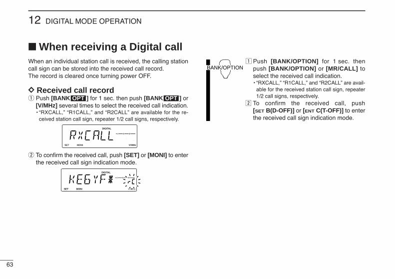
63
12 DIGITAL MODE OPERATION
When receiving a Digital callWhen an individual station call is received, the calling stationcall sign can be stored into the received call record.The record is cleared once turning power OFF.
DD Received call recordq Push [BANK ] for 1 sec. then push [BANK ] or
[V/MHz] several times to select the received call indication.• “RXCALL,” “R1CALL,” and “R2CALL” are available for the re-
ceived station call sign, repeater 1/2 call signs, respectively.
w To confirm the received call, push [SET] or [MONI] to enterthe received call sign indication mode.
z Push [BANK/OPTION] for 1 sec. thenpush [BANK/OPTION] or [MR/CALL] toselect the received call indication.• “RXCALL,” “R1CALL,” and “R2CALL” are avail-
able for the received station call sign, repeater1/2 call signs, respectively.
x To confirm the received call, push[SET B(D-OFF)] or [ENT C(T-OFF)] to enterthe received call sign indication mode.
BANK/OPTION
LOCKSET
ANMMONI
DUPLOW
T-SCANTONE
PRIOM/CALL
SCANV/MHz
DIGITAL PRIO AO BUSYMUTENARMIDLOW
LOCKSET
ANMMONI
DUPLOW
T-SCANTONE
PRIOM/CALL
SCANV/MHz
DIGITAL PRIO AO BUSYMUTENARMIDLOW
OPTOPT

64
12DIGITAL MODE OPERATION
12
DD To reply a callq Push [BANK ] or [V/MHz] several times to select the
call sign select mode.• “YUC” appears for station call sign.• “R1C” or “R2C” appears for repeater call sign.
w Rotate [DIAL] to select the blank channel or erasablechannel.
e Push [BANK ] three times to select the received call in-dication.
r To confirm the received call, push [SET] or [MONI] to enterthe received call sign indication mode.
tPush [S.MW ] for 1 sec. to store the call sign into theselected station call sign channel.
yPush and hold [PTT] to reply a call.
z Push [BANK/OPTION] or [MR/CALL] toselect the call sign select mode.• “YUC” appears for station call sign.• “R1C” or “R2C” appears for repeater call sign.
x Push [YY] or [ZZ] to select the blank chan-nel or erasable channel.
c Push [BANK/OPTION] three times to selectthe received call indication.
v To confirm the received call, push[SET B(D-OFF)] or [ENT C(T-OFF)] to enterthe received call sign indication mode.
b Push [FUNC] then [CLR A(MW)] for 1 sec.to store the call sign into the selected sta-tion call sign channel.
n Push and hold [PTT] to reply a call.
BANK/OPTION
MW
LOCKSET
ANMMONI
DUPLOW
T-SCANTONE
PRIOM/CALL
SCANV/MHz
DIGITAL PRIO AO BUSYMUTENARMIDLOW
OPT
LOCKSET
ANMMONI
DUPLOW
T-SCANTONE
PRIOM/CALL
SCANV/MHz
DIGITAL PRIO AO BUSYMUTENARMIDLOW
LOCKSET
ANMMONI
DUPLOW
T-SCANTONE
PRIOM/CALL
SCANV/MHz
DIGITAL PRIO AO BUSYMUTENARMIDLOW
OPT

65
12 DIGITAL MODE OPERATION
Break-in communicationThe break-in function allows a user to break into a conversa-tion, where the two original stations are communicating withcall sign squelch enabled. The breaking station should enterthe call sign of one of the stations that they wish to communi-cate with. When you call the desired station, only the selectedstation will hear the call. With the break-in function enabled,both stations will be able to hear the call.
q While receiving another station’s transmissions, push[BANK ] for 1 sec. to enter the options set mode.
w Push [BANK ] or [V/MHz] several times to select thestation call sign item, “YUC.” Next enter one of the stationscall signs in the “YUC.”• If the stations are using a local repeater, enter the repeater call
sign in “R1C.” Or if the stations are using a remote repeater,enter the repeater call sign into “R2C.”
e Push [BANK ] or [V/MHz] several times to select theBreak-in item.• “BRK--OF” appears.
r Rotate [DIAL] to turn the brek-in setting ON.• “BRK--ON” appears.
tWhen both stations are in standby, transmit to send abreak-in call.
yWait for the reply call from the station who receive thebreak-in call.
uAfter you receive the reply, communicate in a normal way.iTo cancel the break-in, push [BANK ] for 1 sec., then
rotate [DIAL] to turn OFF.
About the call sign squelch (p.67)Icom’s call sign squelch function opens when;• your own call sign “MYC” (p.58) is called.• the station breaking in calls with the break-in function en-
abled, and the called station and breaking station bothhave the same call sign of the other station set “YUC”(p.59).
OPT
LOCKSET
ANMMONI
DUPLOW
T-SCANTONE
PRIOM/CALL
SCANV/MHz
DIGITAL PRIO AO BUSYMUTENARMIDLOW
LOCKSET
ANMMONI
DUPLOW
T-SCANTONE
PRIOM/CALL
SCANV/MHz
DIGITAL PRIO AO BUSYMUTENARMIDLOW
OPT
OPTOPT
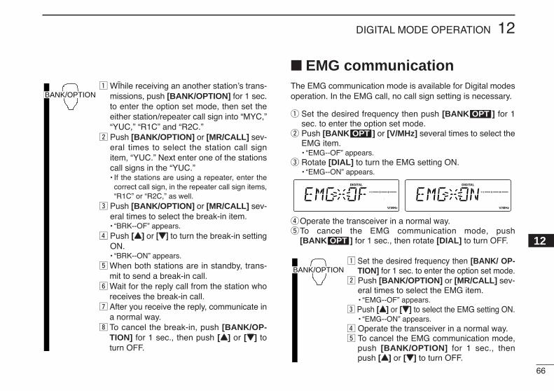
66
12DIGITAL MODE OPERATION
12
z WÏhile receiving an another station’s trans-missions, push [BANK/OPTION] for 1 sec.to enter the option set mode, then set theeither station/repeater call sign into “MYC,”“YUC,” “R1C” and “R2C.”
x Push [BANK/OPTION] or [MR/CALL] sev-eral times to select the station call signitem, “YUC.” Next enter one of the stationscall signs in the “YUC.”• If the stations are using a repeater, enter the
correct call sign, in the repeater call sign items,“R1C” or “R2C,” as well.
c Push [BANK/OPTION] or [MR/CALL] sev-eral times to select the break-in item.• “BRK--OF” appears.
v Push [YY] or [[ZZ]] to turn the break-in settingON.• “BRK--ON” appears.
b When both stations are in standby, trans-mit to send a break-in call.
n Wait for the reply call from the station whoreceives the break-in call.
m After you receive the reply, communicate ina normal way.
, To cancel the break-in, push [BANK/OP-TION] for 1 sec., then push [YY] or [ZZ] toturn OFF.
EMG communicationThe EMG communication mode is available for Digital modesoperation. In the EMG call, no call sign setting is necessary.
q Set the desired frequency then push [BANK ] for 1sec. to enter the option set mode.
w Push [BANK ] or [V/MHz] several times to select theEMG item.• “EMG--OF” appears.
e Rotate [DIAL] to turn the EMG setting ON.• “EMG--ON” appears.
rOperate the transceiver in a normal way.tTo cancel the EMG communication mode, push
[BANK ] for 1 sec., then rotate [DIAL] to turn OFF.
z Set the desired frequency then [BANK/ OP-TION] for 1 sec. to enter the option set mode.
x Push [BANK/OPTION] or [MR/CALL] sev-eral times to select the EMG item.• “EMG--OF” appears.
c Push [YY] or [ZZ] to select the EMG setting ON.• “EMG--ON” appears.
v Operate the transceiver in a normal way.b To cancel the EMG communication mode,
push [BANK/OPTION] for 1 sec., thenpush [YY] or [ZZ] to turn OFF.
BANK/OPTION
OPT
LOCKSET
ANMMONI
DUPLOW
T-SCANTONE
PRIOM/CALL
SCANV/MHz
DIGITAL PRIO AO BUSYMUTENARMIDLOW
LOCKSET
ANMMONI
DUPLOW
T-SCANTONE
PRIOM/CALL
SCANV/MHz
DIGITAL PRIO AO BUSYMUTENARMIDLOW
OPT
OPT
BANK/OPTION
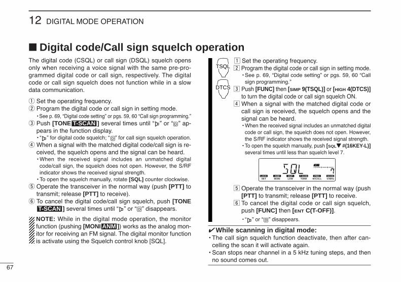
67
12 DIGITAL MODE OPERATION
The digital code (CSQL) or call sign (DSQL) squelch opensonly when receiving a voice signal with the same pre-pro-grammed digital code or call sign, respectively. The digitalcode or call sign squelch does not function while in a slowdata communication.
q Set the operating frequency.w Program the digital code or call sign in setting mode.
• See p. 69, “Digital code setting” or pgs. 59, 60 “Call sign programming.”e Push [TONE ] several times until “ ” or “ ” ap-
pears in the function display.• “ ” for digital code squelch; “ ” for call sign squelch operation.
r When a signal with the matched digital code/call sign is re-ceived, the squelch opens and the signal can be heard.• When the received signal includes an unmatched digital
code/call sign, the squelch does not open. However, the S/RFindicator shows the received signal strength.
• To open the squelch manually, rotate [SQL] counter clockwise.t Operate the transceiver in the normal way (push [PTT] to
transmit; release [PTT] to receive).y To cancel the digital code/call sign squelch, push [TONE
] several times until “ ” or “ ” disappears.
NOTE: While in the digital mode operation, the monitorfunction (pushing [MONI ]) works as the analog mon-itor for receiving an FM signal. The digital monitor functionis activate using the Squelch control knob [SQL].
z Set the operating frequency.x Program the digital code or call sign in setting mode.
• See p. 69, “Digital code setting” or pgs. 59, 60 “Callsign programming.”
c Push [FUNC] then [SIMP 9(TSQL)] or [HIGH 4(DTCS)]to turn the digital code or call sign squelch ON.
v When a signal with the matched digital code orcall sign is received, the squelch opens and thesignal can be heard.• When the received signal includes an unmatched digital
code or call sign, the squelch does not open. However,the S/RF indicator shows the received signal strength.
• To open the squelch manually, push [SQLZZ #(16KEY-L)]several times until less than squelch level 7.
b Operate the transceiver in the normal way (push[PTT] to transmit; release [PTT] to receive.
n To cancel the digital code or call sign squelch,push [FUNC] then [ENT C(T-OFF)].• “ ” or “ ” disappears.
While scanning in digital mode:• The call sign squelch function deactivate, then after can-
celling the scan it will activate again.• Scan stops near channel in a 5 kHz tuning steps, and then
no sound comes out.
LOCKSET
ANMMONI
DUPLOW
T-SCANTONE
PRIOM/CALL
SCANV/MHz
DIGITAL PRIO AO BUSYMUTENARMIDLOW
TSQL
DTCS
ANM
T-SCAN
T-SCAN
Digital code/Call sign squelch operation

68
12DIGITAL MODE OPERATION
12
Slow data communicationIn addition to the digital voice communication, a slow datacommunication is available (Refer p. 5 about the transceiver-PC connection details).
qSet the desired frequency.wSet another settings, such as repeater call, transmit output
power.e Push [BANK ] for 1 sec. then push [BANK ] or
[V/MHz] several times to select the automatic data trans-mission setting. (see p. 69)• “ATX” appears.• Skip this setting, if you want to transmit manually.
r Push [BANK ] once to select the data communica-tion speed setting. (see p. 70)• “SPD” appears.• Select suitable data speed for your PC or application.
tStart up the slow data communication application.ySet the application as follows.
• Port : The same COM port number as IC-2200H’s• Baud rate : 4800 bps or 9600 bps (same as step r)• Data : 8 bit• Parity : None• Stop : 1 bit• Flow control : Xon/Xoff
uTransceiver automatically transmits or receive the datawhen you sending data to transceiver. Or push and hold[PTT] to transmit, release to receive the data manually.• Refer to the instruction of the application that how to send or re-
ceive data.
z Set the desired frequency.x Set another settings, such as repeater call,
transmit output power.c Push [BANK/OPTION] for 1 sec. then
push [BANK/OPTION] or [MR/CALL] toselect the automatic transmission setting.• “ATX” appears.• Skip this setting, if you want to transmit manually.
v Push [BANK/OPTION] to select the datacommunication speed.• “SPD” appears.• Select suitable data speed for your PC or ap-
plication.b Start up the slow data communication ap-
plication, then follow step y at above.
BANK/OPTION
LOCKSET
ANMMONI
DUPLOW
T-SCANTONE
PRIOM/CALL
SCANV/MHz
DIGITAL PRIO AO BUSYMUTENARMIDLOW
LOCKSET
ANMMONI
DUPLOW
T-SCANTONE
PRIOM/CALL
SCANV/MHz
DIGITAL PRIO AO BUSYMUTENARMIDLOW
OPT
LOCKSET
ANMMONI
DUPLOW
T-SCANTONE
PRIOM/CALL
SCANV/MHz
DIGITAL PRIO AO BUSYMUTENARMIDLOW
LOCKSET
ANMMONI
DUPLOW
T-SCANTONE
PRIOM/CALL
SCANV/MHz
DIGITAL PRIO AO BUSYMUTENARMIDLOW
OPTOPT
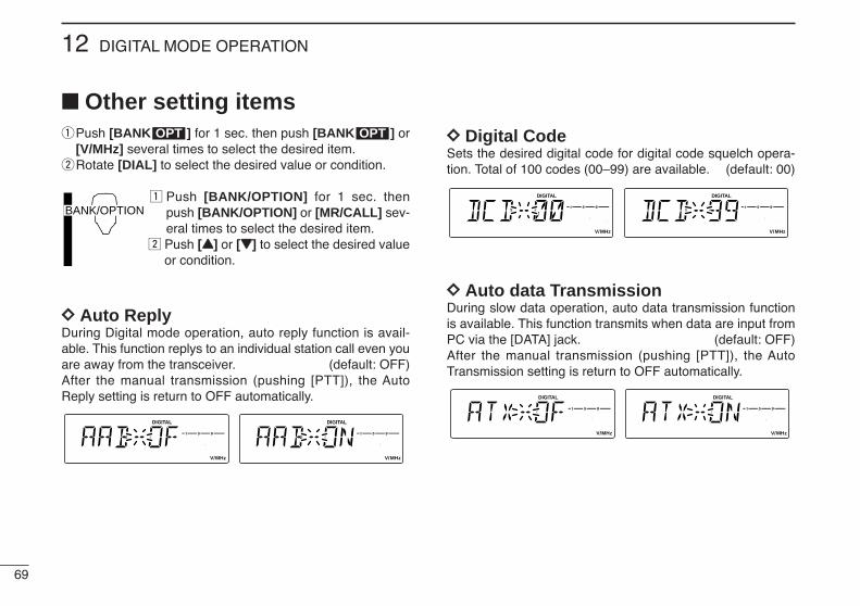
69
12 DIGITAL MODE OPERATION
Other setting itemsqPush [BANK ] for 1 sec. then push [BANK ] or
[V/MHz] several times to select the desired item.wRotate [DIAL] to select the desired value or condition.
z Push [BANK/OPTION] for 1 sec. thenpush [BANK/OPTION] or [MR/CALL] sev-eral times to select the desired item.
x Push [YY] or [ZZ] to select the desired valueor condition.
DD Auto ReplyDuring Digital mode operation, auto reply function is avail-able. This function replys to an individual station call even youare away from the transceiver. (default: OFF)After the manual transmission (pushing [PTT]), the AutoReply setting is return to OFF automatically.
DD Digital CodeSets the desired digital code for digital code squelch opera-tion. Total of 100 codes (00–99) are available. (default: 00)
DD Auto data TransmissionDuring slow data operation, auto data transmission functionis available. This function transmits when data are input fromPC via the [DATA] jack. (default: OFF)After the manual transmission (pushing [PTT]), the AutoTransmission setting is return to OFF automatically.
LOCKSET
ANMMONI
DUPLOW
T-SCANTONE
PRIOM/CALL
SCANV/MHz
DIGITAL PRIO AO BUSYMUTENARMIDLOW
LOCKSET
ANMMONI
DUPLOW
T-SCANTONE
PRIOM/CALL
SCANV/MHz
DIGITAL PRIO AO BUSYMUTENARMIDLOW
LOCKSET
ANMMONI
DUPLOW
T-SCANTONE
PRIOM/CALL
SCANV/MHz
DIGITAL PRIO AO BUSYMUTENARMIDLOW
LOCKSET
ANMMONI
DUPLOW
T-SCANTONE
PRIOM/CALL
SCANV/MHz
DIGITAL PRIO AO BUSYMUTENARMIDLOW
LOCKSET
ANMMONI
DUPLOW
T-SCANTONE
PRIOM/CALL
SCANV/MHz
DIGITAL PRIO AO BUSYMUTENARMIDLOW
LOCKSET
ANMMONI
DUPLOW
T-SCANTONE
PRIOM/CALL
SCANV/MHz
DIGITAL PRIO AO BUSYMUTENARMIDLOW
BANK/OPTION
OPTOPT
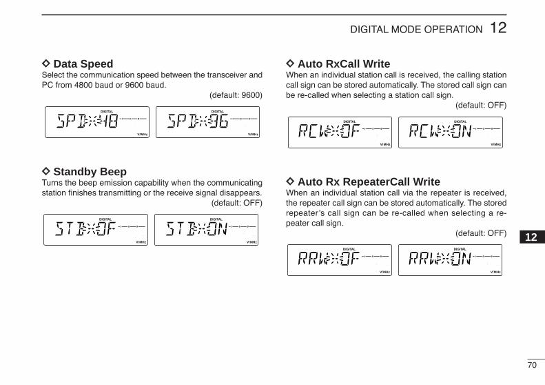
70
12DIGITAL MODE OPERATION
12
DD Data SpeedSelect the communication speed between the transceiver andPC from 4800 baud or 9600 baud.
(default: 9600)
DD Standby BeepTurns the beep emission capability when the communicatingstation finishes transmitting or the receive signal disappears.
(default: OFF)
DD Auto RxCall WriteWhen an individual station call is received, the calling stationcall sign can be stored automatically. The stored call sign canbe re-called when selecting a station call sign.
(default: OFF)
DD Auto Rx RepeaterCall Write When an individual station call via the repeater is received,the repeater call sign can be stored automatically. The storedrepeater’s call sign can be re-called when selecting a re-peater call sign.
(default: OFF)
LOCKSET
ANMMONI
DUPLOW
T-SCANTONE
PRIOM/CALL
SCANV/MHz
DIGITAL PRIO AO BUSYMUTENARMIDLOW
LOCKSET
ANMMONI
DUPLOW
T-SCANTONE
PRIOM/CALL
SCANV/MHz
DIGITAL PRIO AO BUSYMUTENARMIDLOW
LOCKSET
ANMMONI
DUPLOW
T-SCANTONE
PRIOM/CALL
SCANV/MHz
DIGITAL PRIO AO BUSYMUTENARMIDLOW
LOCKSET
ANMMONI
DUPLOW
T-SCANTONE
PRIOM/CALL
SCANV/MHz
DIGITAL PRIO AO BUSYMUTENARMIDLOW
LOCKSET
ANMMONI
DUPLOW
T-SCANTONE
PRIOM/CALL
SCANV/MHz
DIGITAL PRIO AO BUSYMUTENARMIDLOW
LOCKSET
ANMMONI
DUPLOW
T-SCANTONE
PRIOM/CALL
SCANV/MHz
DIGITAL PRIO AO BUSYMUTENARMIDLOW
LOCKSET
ANMMONI
DUPLOW
T-SCANTONE
PRIOM/CALL
SCANV/MHz
DIGITAL PRIO AO BUSYMUTENARMIDLOW
LOCKSET
ANMMONI
DUPLOW
T-SCANTONE
PRIOM/CALL
SCANV/MHz
DIGITAL PRIO AO BUSYMUTENARMIDLOW
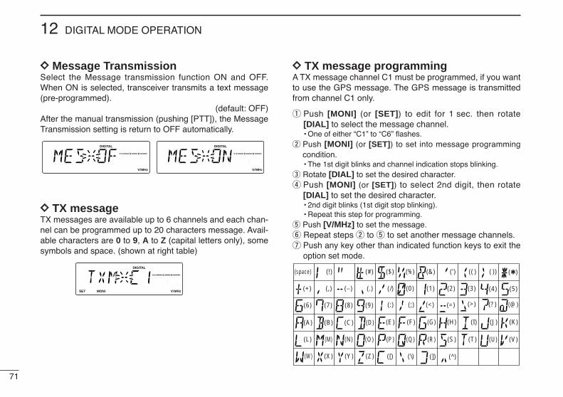
71
12 DIGITAL MODE OPERATION
DD Message TransmissionSelect the Message transmission function ON and OFF.When ON is selected, transceiver transmits a text message(pre-programmed).
(default: OFF) After the manual transmission (pushing [PTT]), the MessageTransmission setting is return to OFF automatically.
DD TX messageTX messages are available up to 6 channels and each chan-nel can be programmed up to 20 characters message. Avail-able characters are 0 to 9, A to Z (capital letters only), somesymbols and space. (shown at right table)
DD TX message programmingA TX message channel C1 must be programmed, if you wantto use the GPS message. The GPS message is transmittedfrom channel C1 only.
q Push [MONI] (or [SET]) to edit for 1 sec. then rotate[DIAL] to select the message channel.• One of either “C1” to “C6” flashes.
w Push [MONI] (or [SET]) to set into message programmingcondition.• The 1st digit blinks and channel indication stops blinking.
e Rotate [DIAL] to set the desired character.r Push [MONI] (or [SET]) to select 2nd digit, then rotate
[DIAL] to set the desired character.• 2nd digit blinks (1st digit stop blinking).• Repeat this step for programming.
t Push [V/MHz] to set the message.y Repeat steps w to t to set another message channels.u Push any key other than indicated function keys to exit the
option set mode.
LOCKSET
ANMMONI
DUPLOW
T-SCANTONE
PRIOM/CALL
SCANV/MHz
DIGITAL PRIO AO BUSYMUTENARMIDLOW
LOCKSET
ANMMONI
DUPLOW
T-SCANTONE
PRIOM/CALL
SCANV/MHz
DIGITAL PRIO AO BUSYMUTENARMIDLOW
LOCKSET
ANMMONI
DUPLOW
T-SCANTONE
PRIOM/CALL
SCANV/MHz
DIGITAL PRIO AO BUSYMUTENARMIDLOW
(3)
(D)
(N)
(X)
(+) (4)
(E)
(O)
(Y)
(–) (5)
(F)
(P)
(Z)
()
(6)
(G)
(Q)
(/)
(7)
(H)
(R)
(,)
(8)
(I)
(S)
(space)
(9)
(T)
(0)
(A)
(U)
(1)
(B)
(V)
(2)
(C) (J) (K)
(L) (M)
(W)
(.)
( ))(( )(’)(&)(%)($)(#)(!)
(<)(:) (;) (=) (>) (?) (@)
([) (\) (]) (^)

72
12DIGITAL MODE OPERATION
12
GPS operationA GPS receiver (RS-232C output/NMEA format/4800 bps)can be connected to [DATA] socket of the IC-2200H to indi-cate the current position (Latitude and Longitude). The posi-tion data can also be transmitted with a message to anotherstation.
DD Position indicationq While connecting a GPS receiver, push [BANK ] for
1 sec. to enter the option set mode.w Push [BANK ] or [V/MHz] several times to select the
GPS setting.• “GPS” appears.
e Rotate [DIAL] to set the suitable sentence formatter for theconnecting GPS receiver.
• Sentence formatters
rPush [BANK ] twice to select the position indication.
tPush [MONI] (or [SET]) to enter the position indication.• Latitude and longitude date appear in order as below.
yAfter checking the current position, push any key otherthan indicated function keys to return to normal operatingmode.
IMPORTANT: When set the sentence formatter at step efor connecting GPS receiver, and already programmed yourcall sign, GPS automatic transmission is activate every 3minutes. The automatic transmission can be changed inter-val time or deactivated, if desired. (see next page)
LOCKSET
ANMMONI
DUPLOW
T-SCANTONE
PRIOM/CALL
SCANV/MHz
DIGITAL PRIO AO BUSYMUTENARMIDLOW
LOCKSET
ANMMONI
DUPLOW
T-SCANTONE
PRIOM/CALL
SCANV/MHz
DIGITAL PRIO AO BUSYMUTENARMIDLOW
LOCKSET
ANMMONI
DUPLOW
T-SCANTONE
PRIOM/CALL
SCANV/MHz
DIGITAL PRIO AO BUSYMUTENARMIDLOW
LOCKSET
ANMMONI
DUPLOW
T-SCANTONE
PRIOM/CALL
SCANV/MHz
DIGITAL PRIO AO BUSYMUTENARMIDLOW
DegreesNorth or South Minutes Seconds
DegreesEast or WestMinutes Seconds
LOCKSET( )Push
MONI( )Push
LOCKSET
ANMMONI
DUPLOW
T-SCANTONE
PRIOM/CALL
SCANV/MHz
DIGITAL PRIO AO BUSYMUTENARMIDLOW
OPT
12345
GLLGGARMCGSAVTG
6789
10
GLL, GGAGLL, RMCGLL, GSAGLL, VTGGGA, RMC
1112131415
GGA, GSAGGA, VTGRMC, GSARMC, VTGGSA, VTG
1617181920
GLL, GGA, RMCGLL, GGA, GSAGLL, GGA, VTGGLL, RMC, GSAGLL, RMC, VTG
2122232425
GLL, GSA, VTGGGA, RMC, GSAGGA, RMC, VTGGGA, GSA, VTGRMC, GSA, VTG
LOCKSET
ANMMONI
DUPLOW
T-SCANTONE
PRIOM/CALL
SCANV/MHz
DIGITAL PRIO AO BUSYMUTENARMIDLOW
LOCKSET
ANMMONI
DUPLOW
T-SCANTONE
PRIOM/CALL
SCANV/MHz
DIGITAL PRIO AO BUSYMUTENARMIDLOW
OPT
OPT
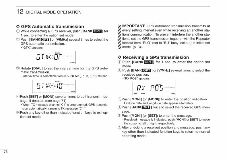
73
12 DIGITAL MODE OPERATION
DD GPS Automatic transmissionq While connecting a GPS receiver, push [BANK ] for
1 sec. to enter the option set mode.w Push [BANK ] or [V/MHz] several times to select the
GPS automatic transmission.• “GTX” appears.
e Rotate [DIAL] to set the interval time for the GPS auto-matic transmission.• Interval time is selectable from 0.5 (30 sec.), 1, 3, 5, 10, 30 min.
rPush [SET] or [MONI] several times to edit transmit mes-sage, if desired. (see page 71)• When TX message channel “C1” is programmed, GPS transmis-
sion automatically transmits TX message “C1.”tPush any key other than indicated function keys to exit op-
tion set mode.
IMPORTANT: GPS Automatic transmission transmits atevery setting interval even while receiving an another sta-tions communication. To prevent interfere the another sta-tions, set the GPS transmission together with the Repeaterlockout item “RLO” (set to “BU” busy lockout) in initial setmode. (p. 84)
DD Receiving a GPS transmissionq Push [BANK ] for 1 sec. to enter the option set
mode.w Push [BANK ] or [V/MHz] several times to select the
received position.• “RX POS” appears.
ePush [MONI] (or [MONI]) to enter the position indication.• Latitude data and longitude date appear alternately.
rPush [BANK ] twice to select the received GPS mes-sage.
tPush [MONI] (or [SET]) to enter the message.• Received message is indicated, push [MONI] or [SET] to move
the cursor to left or right, respectively.yAfter checking a received position and message, push any
key other than indicated function keys to return to normaloperating mode.
OPT
LOCKSET
ANMMONI
DUPLOW
T-SCANTONE
PRIOM/CALL
SCANV/MHz
DIGITAL PRIO AO BUSYMUTENARMIDLOW
OPT
OPT
LOCKSET
ANMMONI
DUPLOW
T-SCANTONE
PRIOM/CALL
SCANV/MHz
DIGITAL PRIO AO BUSYMUTENARMIDLOW
LOCKSET
ANMMONI
DUPLOW
T-SCANTONE
PRIOM/CALL
SCANV/MHz
DIGITAL PRIO AO BUSYMUTENARMIDLOW
OPT
OPT
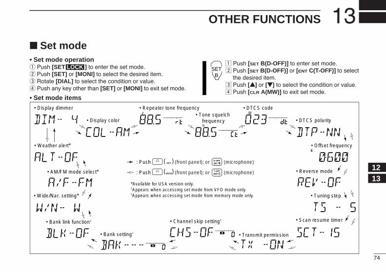
74
13OTHER FUNCTIONS
1213
Set mode• Set mode operationq Push [SET ] to enter the set mode.w Push [SET] or [MONI] to select the desired item.e Rotate [DIAL] to select the condition or value.r Push any key other than [SET] or [MONI] to exit set mode.
• Set mode items
z Push [SET B(D-OFF)] to enter set mode.x Push [SET B(D-OFF)] or [ENT C(T-OFF)] to select
the desired item.c Push [YY] or [ZZ] to select the condition or value.v Push [CLR A(MW)] to exit set mode.
SETB
LOCK
• Weather alert*
• AM/FM mode select*
• Display dimmer
• Display color
• Repeater tone frequency• Tone squelch
frequency
• DTCS code
• DTCS polarity
• Offset frequency
• Tuning step
• Reverse mode
• Scan resume timer• Channel skip setting‡• Bank link function‡
• Bank setting‡
• Wide/Nar. setting*
• Transmit permission
*Available for USA version only.†Appears when accessing set mode from VFO mode only.‡Appears when accessing set mode from memory mode only.
(front panel); or (microphone)
(front panel); or (microphone)
( )
( )
LOCKSET: Push
ANMMONI: Push
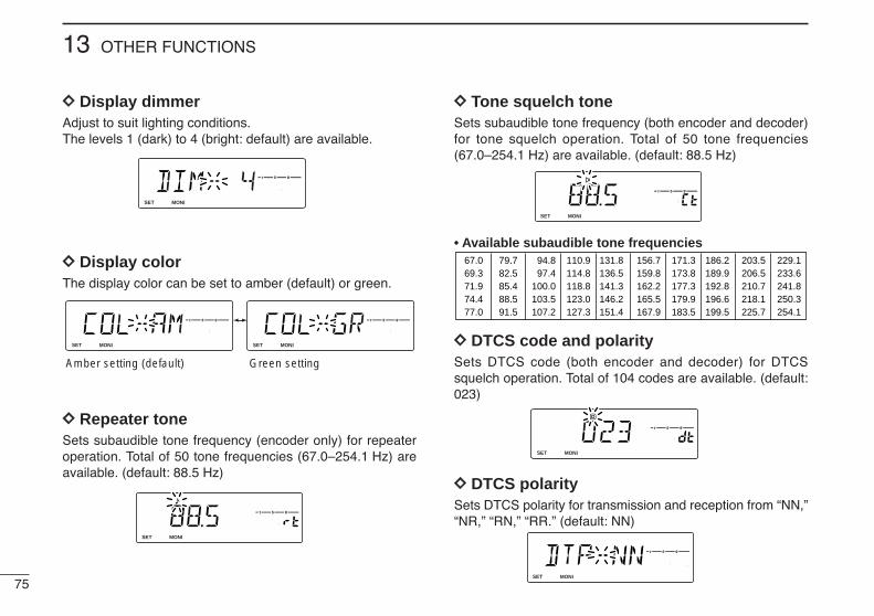
75
13 OTHER FUNCTIONS
DD Display dimmerAdjust to suit lighting conditions.The levels 1 (dark) to 4 (bright: default) are available.
DD Display colorThe display color can be set to amber (default) or green.
DD Repeater tone Sets subaudible tone frequency (encoder only) for repeateroperation. Total of 50 tone frequencies (67.0–254.1 Hz) areavailable. (default: 88.5 Hz)
DD Tone squelch toneSets subaudible tone frequency (both encoder and decoder)for tone squelch operation. Total of 50 tone frequencies(67.0–254.1 Hz) are available. (default: 88.5 Hz)
• Available subaudible tone frequencies
DD DTCS code and polaritySets DTCS code (both encoder and decoder) for DTCSsquelch operation. Total of 104 codes are available. (default:023)
DD DTCS polaritySets DTCS polarity for transmission and reception from “NN,”“NR,” “RN,” “RR.” (default: NN)
LOCKSET
ANMMONI
DUPLOW
T-SCANTONE
PRIOM/CALL
SCANV/MHz
DIGITAL PRIO AO BUSYMUTENARMIDLOW
LOCKSET
ANMMONI
DUPLOW
T-SCANTONE
PRIOM/CALL
SCANV/MHz
DIGITAL PRIO AO BUSYMUTENARMIDLOW
67.069.371.974.477.0
79.782.585.488.591.5
94.897.4
100.0103.5107.2
110.9114.8118.8123.0127.3
131.8136.5141.3146.2151.4
156.7159.8162.2165.5167.9
171.3173.8177.3179.9183.5
186.2189.9192.8196.6199.5
203.5206.5210.7218.1225.7
229.1233.6241.8250.3254.1
LOCKSET
ANMMONI
DUPLOW
T-SCANTONE
PRIOM/CALL
SCANV/MHz
DIGITAL PRIO AO BUSYMUTENARMIDLOW
LOCKSET
ANMMONI
DUPLOW
T-SCANTONE
PRIOM/CALL
SCANV/MHz
DIGITAL PRIO AO BUSYMUTENARMIDLOW
LOCKSET
ANMMONI
DUPLOW
T-SCANTONE
PRIOM/CALL
SCANV/MHz
DIGITAL PRIO AO BUSYMUTENARMIDLOW
LOCKSET
ANMMONI
DUPLOW
T-SCANTONE
PRIOM/CALL
SCANV/MHz
DIGITAL PRIO AO BUSYMUTENARMIDLOW
Amber setting (default) Green setting
LOCKSET
ANMMONI
DUPLOW
T-SCANTONE
PRIOM/CALL
SCANV/MHz
DIGITAL PRIO AO BUSYMUTENARMIDLOW
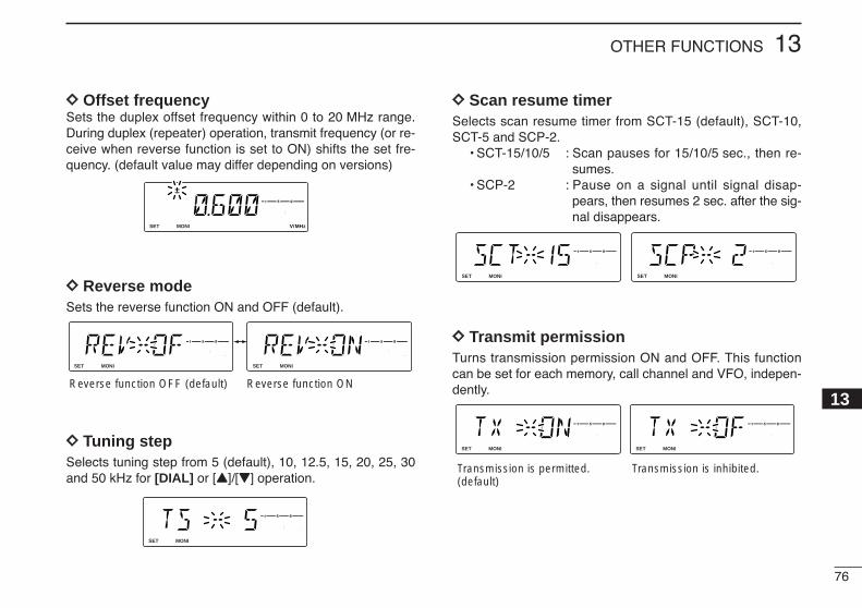
76
13OTHER FUNCTIONS
13
DD Offset frequencySets the duplex offset frequency within 0 to 20 MHz range.During duplex (repeater) operation, transmit frequency (or re-ceive when reverse function is set to ON) shifts the set fre-quency. (default value may differ depending on versions)
DD Reverse modeSets the reverse function ON and OFF (default).
DD Tuning stepSelects tuning step from 5 (default), 10, 12.5, 15, 20, 25, 30and 50 kHz for [DIAL] or [Y]/[Z] operation.
DD Scan resume timerSelects scan resume timer from SCT-15 (default), SCT-10,SCT-5 and SCP-2.
• SCT-15/10/5 : Scan pauses for 15/10/5 sec., then re-sumes.
• SCP-2 : Pause on a signal until signal disap-pears, then resumes 2 sec. after the sig-nal disappears.
DD Transmit permissionTurns transmission permission ON and OFF. This functioncan be set for each memory, call channel and VFO, indepen-dently.
LOCKSET
ANMMONI
DUPLOW
T-SCANTONE
PRIOM/CALL
SCANV/MHz
DIGITAL PRIO AO BUSYMUTENARMIDLOW
LOCKSET
ANMMONI
DUPLOW
T-SCANTONE
PRIOM/CALL
SCANV/MHz
DIGITAL PRIO AO BUSYMUTENARMIDLOW
Transmission is permitted. (default)
Transmission is inhibited.
LOCKSET
ANMMONI
DUPLOW
T-SCANTONE
PRIOM/CALL
SCANV/MHz
DIGITAL PRIO AO BUSYMUTENARMIDLOW
LOCKSET
ANMMONI
DUPLOW
T-SCANTONE
PRIOM/CALL
SCANV/MHz
DIGITAL PRIO AO BUSYMUTENARMIDLOW
LOCKSET
ANMMONI
DUPLOW
T-SCANTONE
PRIOM/CALL
SCANV/MHz
DIGITAL PRIO AO BUSYMUTENARMIDLOW
LOCKSET
ANMMONI
DUPLOW
T-SCANTONE
PRIOM/CALL
SCANV/MHz
DIGITAL PRIO AO BUSYMUTENARMIDLOW
LOCKSET
ANMMONI
DUPLOW
T-SCANTONE
PRIOM/CALL
SCANV/MHz
DIGITAL PRIO AO BUSYMUTENARMIDLOW
Reverse function OFF (default) Reverse function ON
LOCKSET
ANMMONI
DUPLOW
T-SCANTONE
PRIOM/CALL
SCANV/MHz
DIGITAL PRIO AO BUSYMUTENARMIDLOW
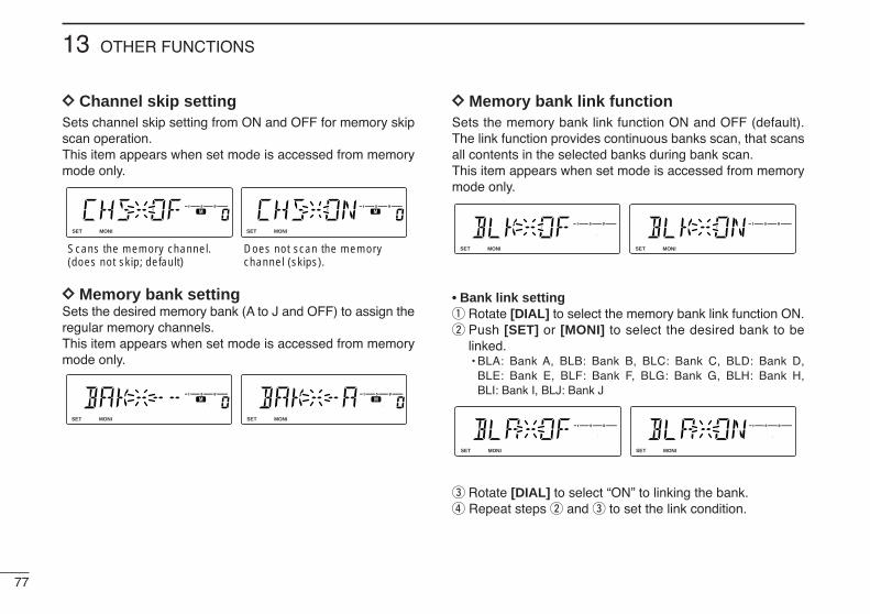
77
13 OTHER FUNCTIONS
DD Channel skip settingSets channel skip setting from ON and OFF for memory skipscan operation. This item appears when set mode is accessed from memorymode only.
DD Memory bank settingSets the desired memory bank (A to J and OFF) to assign theregular memory channels.This item appears when set mode is accessed from memorymode only.
DD Memory bank link functionSets the memory bank link function ON and OFF (default).The link function provides continuous banks scan, that scansall contents in the selected banks during bank scan.This item appears when set mode is accessed from memorymode only.
• Bank link settingq Rotate [DIAL] to select the memory bank link function ON.w Push [SET] or [MONI] to select the desired bank to be
linked.• BLA: Bank A, BLB: Bank B, BLC: Bank C, BLD: Bank D,
BLE: Bank E, BLF: Bank F, BLG: Bank G, BLH: Bank H, BLI: Bank I, BLJ: Bank J
e Rotate [DIAL] to select “ON” to linking the bank.r Repeat steps w and e to set the link condition.
LOCKSET
ANMMONI
DUPLOW
T-SCANTONE
PRIOM/CALL
SCANV/MHz
DIGITAL PRIO AO BUSYMUTENARMIDLOW
LOCKSET
ANMMONI
DUPLOW
T-SCANTONE
PRIOM/CALL
SCANV/MHz
DIGITAL PRIO AO BUSYMUTENARMIDLOW
LOCKSET
ANMMONI
DUPLOW
T-SCANTONE
PRIOM/CALL
SCANV/MHz
DIGITAL PRIO AO BUSYMUTENARMIDLOW
LOCKSET
ANMMONI
DUPLOW
T-SCANTONE
PRIOM/CALL
SCANV/MHz
DIGITAL PRIO AO BUSYMUTENARMIDLOW
LOCKSET
ANMMONI
DUPLOW
T-SCANTONE
PRIOM/CALL
SCANV/MHz
DIGITAL PRIO AO BUSYMUTENARMIDLOW
LOCKSET
ANMMONI
DUPLOW
T-SCANTONE
PRIOM/CALL
SCANV/MHz
DIGITAL PRIO AO BUSYMUTENARMIDLOW
LOCKSET
ANMMONI
DUPLOW
T-SCANTONE
PRIOM/CALL
SCANV/MHz
DIGITAL PRIO AO BUSYMUTENARMIDLOW
LOCKSET
ANMMONI
DUPLOW
T-SCANTONE
PRIOM/CALL
SCANV/MHz
DIGITAL PRIO AO BUSYMUTENARMIDLOW
Scans the memory channel.(does not skip; default)
Does not scan the memorychannel (skips).

78
13OTHER FUNCTIONS
13
DD Wide/Narrow settingSets both the transmission and reception passband widthfrom wide and narrow. When narrow is set, the transmission deviation and receptionpassband width become half of the wide setting (approx.). This setting can be set for each memory, call and VFO inde-pendently.
NOTE: This item MUST be set “W” (WIDE) when operatingthe digital mode.
DD AM/FM mode selectionSets the operating mode for receiving from AM or FM mode(default).
NOTE: This item MUST be set “FM” when operating thedigital mode.
DD Weather alert functionTurns weather alert function ON and OFF.
LOCKSET
ANMMONI
DUPLOW
T-SCANTONE
PRIOM/CALL
SCANV/MHz
DIGITAL PRIO AO BUSYMUTENARMIDLOW
LOCKSET
ANMMONI
DUPLOW
T-SCANTONE
PRIOM/CALL
SCANV/MHz
DIGITAL PRIO AO BUSYMUTENARMIDLOW
Weather alert OFF (default) Weather alert ON
U.S.A. versions only
LOCKSET
ANMMONI
DUPLOW
T-SCANTONE
PRIOM/CALL
SCANV/MHz
DIGITAL PRIO AO BUSYMUTENARMIDLOW
LOCKSET
ANMMONI
DUPLOW
T-SCANTONE
PRIOM/CALL
SCANV/MHz
DIGITAL PRIO AO BUSYMUTENARMIDLOW
FM mode selection (default) AM mode selection
LOCKSET
ANMMONI
DUPLOW
T-SCANTONE
PRIOM/CALL
SCANV/MHz
DIGITAL PRIO AO BUSYMUTENARMIDLOW
LOCKSET
ANMMONI
DUPLOW
T-SCANTONE
PRIOM/CALL
SCANV/MHz
DIGITAL PRIO AO BUSYMUTENARMIDLOW
Wide setting (default) Narrow setting
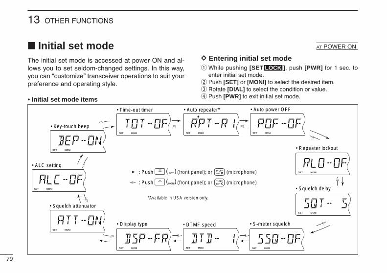
79
13 OTHER FUNCTIONS
Initial set modeThe initial set mode is accessed at power ON and al-lows you to set seldom-changed settings. In this way,you can “customize” transceiver operations to suit yourpreference and operating style.
• Initial set mode items
DD Entering initial set modeq While pushing [SET ], push [PWR] for 1 sec. to
enter initial set mode.w Push [SET] or [MONI] to select the desired item.e Rotate [DIAL] to select the condition or value.r Push [PWR] to exit initial set mode.
LOCK
LOCKSET
ANMMONI
DUPLOW
T-SCANTONE
DIGITALMUTENARMIDLOW
LOCKSET
ANMMONI
DUPLOW
T-SCANTONE
DIGITALMUTENARMIDLOW
LOCKSET
ANMMONI
DUPLOW
T-SCANTONE
DIGITALMUTENARMIDLOW
LOCKSET
ANMMONI
DUPLOW
T-SCANTONE
DIGITALMUTENARMIDLOW
LOCKSET
ANMMONI
DUPLOW
T-SCANTONE
DIGITALMUTENARMIDLOW
LOCKSET
ANMMONI
DUPLOW
T-SCANTONE
DIGITALMUTENARMIDLOW
LOCKSET
ANMMONI
DUPLOW
T-SCANTONE
DIGITALMUTENARMIDLOW
LOCKSET
ANMMONI
DUPLOW
T-SCANTONE
DIGITALMUTENARMIDLOW
LOCKSET
ANMMONI
DUPLOW
T-SCANTONE
DIGITALMUTENARMIDLOW
LOCKSET
ANMMONI
DUPLOW
T-SCANTONE
DIGITALMUTENARMIDLOW
LOCKSET
ANMMONI
DUPLOW
T-SCANTONE
DIGITALMUTENARMIDLOW
(front panel); or (microphone)
*Available in USA version only.
(front panel); or (microphone)
• Key-touch beep
• ALC setting
• Time-out timer • Auto repeater* • Auto power OFF
• Repeater lockout
• Squelch delay
• S-meter squelch• DTMF speed• Display type
• Squelch attenuator
( )
( )
LOCKSET: Push
ANMMONI: Push
AT POWER ON
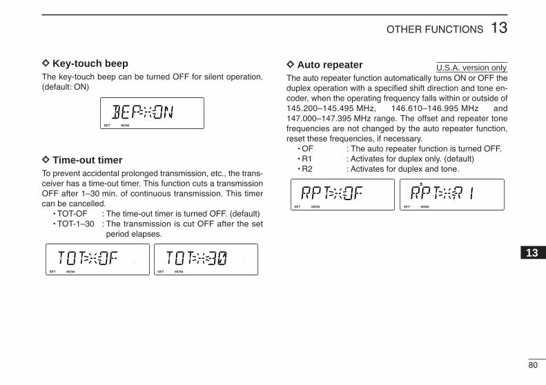
80
13OTHER FUNCTIONS
13
DD Key-touch beepThe key-touch beep can be turned OFF for silent operation.(default: ON)
DD Time-out timerTo prevent accidental prolonged transmission, etc., the trans-ceiver has a time-out timer. This function cuts a transmissionOFF after 1–30 min. of continuous transmission. This timercan be cancelled.
• TOT-OF : The time-out timer is turned OFF. (default)• TOT-1–30 : The transmission is cut OFF after the set
period elapses.
DD Auto repeaterThe auto repeater function automatically turns ON or OFF theduplex operation with a specified shift direction and tone en-coder, when the operating frequency falls within or outside of145.200–145.495 MHz, 146.610–146.995 MHz and147.000–147.395 MHz range. The offset and repeater tonefrequencies are not changed by the auto repeater function,reset these frequencies, if necessary.
• OF : The auto repeater function is turned OFF.• R1 : Activates for duplex only. (default)• R2 : Activates for duplex and tone.
LOCKSET
ANMMONI
DUPLOW
T-SCANTONE
PRIOM/CALL
SCANV/MHz
DIGITAL PRIO AO BUSYMUTENARMIDLOW
LOCKSET
ANMMONI
DUPLOW
T-SCANTONE
PRIOM/CALL
SCANV/MHz
DIGITAL PRIO AO BUSYMUTENARMIDLOW
U.S.A. version only
LOCKSET
ANMMONI
DUPLOW
T-SCANTONE
PRIOM/CALL
SCANV/MHz
DIGITAL PRIO AO BUSYMUTENARMIDLOW
LOCKSET
ANMMONI
DUPLOW
T-SCANTONE
PRIOM/CALL
SCANV/MHz
DIGITAL PRIO AO BUSYMUTENARMIDLOW
LOCKSET
ANMMONI
DUPLOW
T-SCANTONE
PRIOM/CALL
SCANV/MHz
DIGITAL PRIO AO BUSYMUTENARMIDLOW
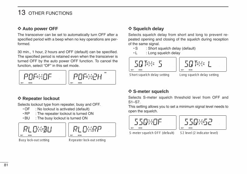
81
13 OTHER FUNCTIONS
DD Auto power OFFThe transceiver can be set to automatically turn OFF after aspecified period with a beep when no key operations are per-formed.
30 min., 1 hour, 2 hours and OFF (default) can be specified.The specified period is retained even when the transceiver isturned OFF by the auto power OFF function. To cancel thefunction, select “OF” in this set mode.
DD Repeater lockoutSelects lockout type from repeater, busy and OFF.
• OF : No lockout is activated (default)• RP : The repeater lockout is turned ON• BU : The busy lockout is turned ON
DD Squelch delaySelects squelch delay from short and long to prevent re-peated opening and closing of the squelch during receptionof the same signal.
• S : Short squelch delay (default)• L : Long squelch delay
DD S-meter squelchSelects S-meter squelch threshold level from OFF andS1–S7.This setting allows you to set a minimum signal level needs toopen the squelch.
LOCKSET
ANMMONI
DUPLOW
T-SCANTONE
PRIOM/CALL
SCANV/MHz
DIGITAL PRIO AO BUSYMUTENARMIDLOW
LOCKSET
ANMMONI
DUPLOW
T-SCANTONE
PRIOM/CALL
SCANV/MHz
DIGITAL PRIO AO BUSYMUTENARMIDLOW
S-meter squelch OFF (default) S2 level (2 indicator level)
LOCKSET
ANMMONI
DUPLOW
T-SCANTONE
PRIOM/CALL
SCANV/MHz
DIGITAL PRIO AO BUSYMUTENARMIDLOW
LOCKSET
ANMMONI
DUPLOW
T-SCANTONE
PRIOM/CALL
SCANV/MHz
DIGITAL PRIO AO BUSYMUTENARMIDLOW
Short squelch delay setting Long squelch delay setting
LOCKSET
ANMMONI
DUPLOW
T-SCANTONE
PRIOM/CALL
SCANV/MHz
DIGITAL PRIO AO BUSYMUTENARMIDLOW
LOCKSET
ANMMONI
DUPLOW
T-SCANTONE
PRIOM/CALL
SCANV/MHz
DIGITAL PRIO AO BUSYMUTENARMIDLOW
Busy lock-out setting Repeater lock-out setting
LOCKSET
ANMMONI
DUPLOW
T-SCANTONE
PRIOM/CALL
SCANV/MHz
DIGITAL PRIO AO BUSYMUTENARMIDLOW
LOCKSET
ANMMONI
DUPLOW
T-SCANTONE
PRIOM/CALL
SCANV/MHz
DIGITAL PRIO AO BUSYMUTENARMIDLOW
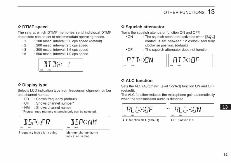
82
13OTHER FUNCTIONS
13
DD DTMF speedThe rate at which DTMF memories send individual DTMFcharacters can be set to accommodate operating needs.
• 1 : 100 msec. interval; 5.0 cps speed (default)• 2 : 200 msec. interval; 2.5 cps speed • 3 : 300 msec. interval; 1.6 cps speed • 5 : 500 msec. interval; 1.0 cps speed
DD Display typeSelects LCD indication type from frequency, channel numberand channel names.
• FR : Shows frequency (default)• CH : Shows channel number*• NM : Shows channel names*Programmed memory channels only can be selected.
DD Squelch attenuatorTurns the squelch attenuator function ON and OFF.
• ON : The squelch attenuator activates when [SQL]control is set between 12 o’clock and fullyclockwise position. (default)
• OF : The squelch attenuator does not function.
DD ALC functionSets the ALC (Automatic Level Control) function ON and OFF(default).The ALC function reduces the microphone gain automaticallywhen the transmission audio is distorted.
LOCKSET
ANMMONI
DUPLOW
T-SCANTONE
PRIOM/CALL
SCANV/MHz
DIGITAL PRIO AO BUSYMUTENARMIDLOW
LOCKSET
ANMMONI
DUPLOW
T-SCANTONE
PRIOM/CALL
SCANV/MHz
DIGITAL PRIO AO BUSYMUTENARMIDLOW
ALC function OFF (default) ALC function ON
LOCKSET
ANMMONI
DUPLOW
T-SCANTONE
PRIOM/CALL
SCANV/MHz
DIGITAL PRIO AO BUSYMUTENARMIDLOW
LOCKSET
ANMMONI
DUPLOW
T-SCANTONE
PRIOM/CALL
SCANV/MHz
DIGITAL PRIO AO BUSYMUTENARMIDLOW
LOCKSET
ANMMONI
DUPLOW
T-SCANTONE
PRIOM/CALL
SCANV/MHz
DIGITAL PRIO AO BUSYMUTENARMIDLOW
LOCKSET
ANMMONI
DUPLOW
T-SCANTONE
PRIOM/CALL
SCANV/MHz
DIGITAL PRIO AO BUSYMUTENARMIDLOW
Frequency indication setting Memory channel name indication setting
LOCKSET
ANMMONI
DUPLOW
T-SCANTONE
PRIOM/CALL
SCANV/MHz
DIGITAL PRIO AO BUSYMUTENARMIDLOW

83
13 OTHER FUNCTIONS
Weather channel operation
DD Weather channel selection
q Push [M/CALL ] sev-eral times to select weatherchannel group.
w Rotate [DIAL] to select thedesired weather channel.
e Push [M/CALL ] toselect memory mode, orpush [V/MHz ] to se-lect VFO mode.
DD Weather alert functionNOAA broadcast stations transmit weather alert tones beforeimportant weather announcements. When the weather alertfunction is turned ON, the selected weather channel is moni-tored each 5 sec. for the announcement. When the alert sig-nal is detected, the “AL.T” and the WX channel are displayedalternately and sounds a beep tone until the transceiver is op-erated. The previously selected (used) weather channel ischecked periodically during standby or while scanning.
q Select the desired weather channel.w Turn the weather alert function ON in set mode.
Push [SET ] to enter set mode. Push [SET ] or [S.MW ] to select the
weather alert item, then rotate [DIAL] to set ON. Push [TONE ] to exit set mode.
e Sets the desired stand-by condition.• Selects VFO, memory or call channel.• Scan or priority watch operation can also be selected.
r When the alert is detected, a beep sounds and the follow-ing indication will be displayed.
t Turn the weather alert function OFF in set mode.
LOCKSET
ANMMONI
DUPLOW
T-SCANTONE
PRIOM/CALL
SCANV/MHz
DIGITAL PRIO AO BUSYMUTENARMIDLOW
LOCKSET
ANMMONI
DUPLOW
T-SCANTONE
PRIOM/CALL
SCANV/MHz
DIGITAL PRIO AO BUSYMUTENARMIDLOW
Shows above indications alternately.
T-SCAN
MWLOCKLOCK
SCAN
PRIO
PRIO
LOCKSET
ANMMONI
DUPLOW
T-SCANTONE
PRIOM/CALL
SCANV/MHz
DIGITAL PRIO AO BUSYMUTENARMIDLOW
NOTE: While receiving a signal (on a frequency other thanthe weather alert ON frequency), the receiving signal oraudio will be interrupted momentarily every 5 sec. (approx.)in case the alert function is turned ON. This symptom iscaused by the WX alert function. To cancel these symp-toms, set the weather alert item OFF in set mode.
U.S.A. versions only
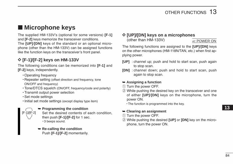
84
13OTHER FUNCTIONS
13
Microphone keysThe supplied HM-133V’s (optional for some versions) [F-1]and [F-2] keys memorize the transceiver conditions. The [UP]/[DN] keys of the standard or an optional micro-phone (other than the HM-133V) can be assigned functionslike the function keys on the transceiver’s front panel.
DD [F-1]/[F-2] keys on HM-133VThe following conditions can be memorized into [F-1] and [F-2] keys, independently.
• Operating frequency• Repeater setting (offset direction and frequency, tone
ON/OFF and frequency)• Tone/DTCS squelch (ON/OFF, frequency/code and polarity)• Transmit output power selection• Set mode settings• Initial set mode settings (except display type item)
Programming the conditionSet the desired contents of each condition,then push [F-1]/[F-2] for 1 sec.• 3 beeps sound.
Re-calling the conditionPush [F-1]/[F-2] momentarily.
DD [UP]/[DN] keys on a microphones(other than HM-133V)
The following functions are assigned to the [UP]/[DN] keyson the other microphones (HM-118N/TAN, etc.) when first ap-plying power.
[UP] : channel up; push and hold to start scan, push againto stop scan.
[DN] : channel down; push and hold to start scan, pushagain to stop scan.
Assigning a functionq Turn the power OFF.w While pushing the desired key on the transceiver and one
of either [UP]/[DN] keys on the microphone, turn thepower ON.• The function is programmed into the key.
Clearing an assignmentq Turn the power OFF.w While pushing the desired [UP] or [DN] key on the micro-
phone, turn the power ON.
AT POWER ON
[F-1]/[F-2]
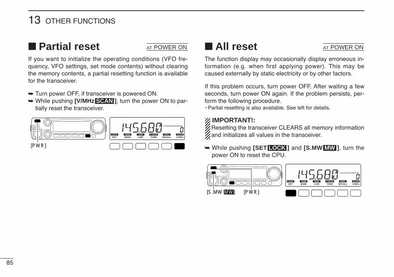
85
13 OTHER FUNCTIONS
Partial resetIf you want to initialize the operating conditions (VFO fre-quency, VFO settings, set mode contents) without clearingthe memory contents, a partial resetting function is availablefor the transceiver.
Turn power OFF, if transceiver is powered ON. While pushing [V/MHz ], turn the power ON to par-
tially reset the transceiver.
All resetThe function display may occasionally display erroneous in-formation (e.g. when first applying power). This may becaused externally by static electricity or by other factors.
If this problem occurs, turn power OFF. After waiting a fewseconds, turn power ON again. If the problem persists, per-form the following procedure.• Partial resetting is also available. See left for details.
IMPORTANT!:Resetting the transceiver CLEARS all memory informationand initializes all values in the transceiver.
While pushing [SET ] and [S.MW ], turn thepower ON to reset the CPU.
LOCKSET
ANMMONI
DUPLOW
T-SCANTONE
PRIOM/CALL
SCANV/MHz
DIGITAL PRIO AO BUSYMUTENARMIDLOW
[PWR][S.MW MW]
MWLOCK
AT POWER ON
LOCKSET
ANMMONI
DUPLOW
T-SCANTONE
PRIOM/CALL
SCANV/MHz
DIGITAL PRIO AO BUSYMUTENARMIDLOW
[PWR]
SCAN
AT POWER ON
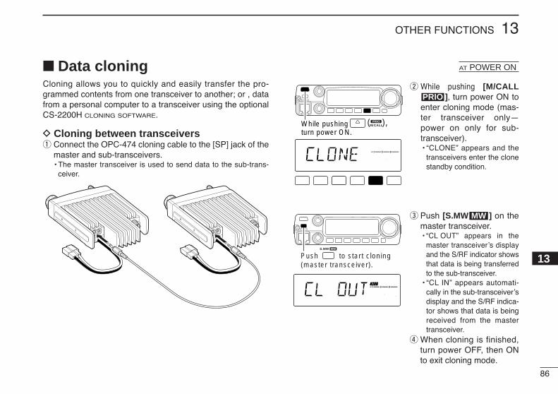
86
13OTHER FUNCTIONS
13
Data cloningCloning allows you to quickly and easily transfer the pro-grammed contents from one transceiver to another; or , datafrom a personal computer to a transceiver using the optionalCS-2200H CLONING SOFTWARE.
D Cloning between transceiversq Connect the OPC-474 cloning cable to the [SP] jack of the
master and sub-transceivers.• The master transceiver is used to send data to the sub-trans-
ceiver.
w While pushing [M/CALL], turn power ON to
enter cloning mode (mas-ter transceiver only—power on only for sub-transceiver).• “CLONE” appears and the
transceivers enter the clonestandby condition.
e Push [S.MW ] on themaster transceiver.• “CL OUT” appears in the
master transceiver’s displayand the S/RF indicator showsthat data is being transferredto the sub-transceiver.
• “CL IN” appears automati-cally in the sub-transceiver’sdisplay and the S/RF indica-tor shows that data is beingreceived from the mastertransceiver.
r When cloning is finished,turn power OFF, then ONto exit cloning mode.
MW
LOCKSET
ANMMONI
DUPLOW
T-SCANTONE
PRIOM/CALL
SCANV/MHz
DIGITAL PRIO AO BUSYMUTENARMIDLOW
Push to start cloning (master transceiver).
MWS.MW
PRIO
LOCKSET
ANMMONI
DUPLOW
T-SCANTONE
PRIOM/CALL
SCANV/MHz
DIGITAL PRIO AO BUSYMUTENARMIDLOW
PRIOM/CALL( ),While pushing
turn power ON.
AT POWER ON
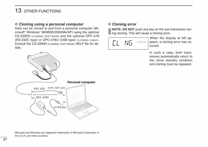
87
13 OTHER FUNCTIONS
D Cloning using a personal computerData can be cloned to and from a personal computer (Mi-crosoft® Windows® 98/98SE/2000/Me/XP) using the optionalCS-2200H CLONING SOFTWARE and the optional OPC-478(RS-232C type) or OPC-478U (USB type) CLONING CABLE.Consult the CS-2200H CLONING SOFTWARE HELP file for de-tails.
D Cloning errorNOTE: DO NOT push any key on the sub-transceiver dur-ing cloning. This will cause a cloning error.
When the display at left ap-pears, a cloning error has oc-curred.
In such a case, both trans-ceivers automatically return tothe clone standby conditionand cloning must be repeated.
LOCKSET
ANMMONI
DUPLOW
T-SCANTONE
PRIOM/CALL
SCANV/MHz
DIGITAL PRIO AO BUSYMUTENARMIDLOW
Personal computer
to USB port
to RS-232C portOPC-478
OPC-478Uor
Microsoft and Windows are registered trademarks of Microsoft Corporation inthe U.S.A. and other countries.
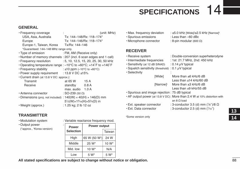
88
14SPECIFICATIONS
1314
GENERAL• Frequency coverage : (unit: MHz)
USA, Asia, Australia Tx: 144–148/Rx: 118–174*Europe Tx: 144–146/Rx: 118–174*Europe-1, Taiwan, Korea Tx/Rx: 144–146*Guaranteed: 144–148 MHz range only.
• Type of emission : FM, AM (Receive only)• Number of memory channels : 207 (incl. 6 scan edges and 1 call)• Frequency resolution : 5, 10, 12.5, 15, 20, 25, 30, 50 kHz• Operating temperature range : –10°C to +60°C; +14˚F to +140˚F• Frequency stability : ±10 ppm (–10°C to +60°C)• Power supply requirement : 13.8 V DC ±15%• Current drain (at 13.8 V DC: approx.):
Transmit at 65 W 15 AReceive standby 0.8 A
max. audio 1.0 A• Antenna connector : SO-239 (50 Ω)• Dimensions (proj. not included) : 140(W) × 40(H) × 146(D) mm
51⁄2(W)×19⁄16(H)×53⁄4(D) in• Weight (approx.) : 1.25 kg; 2 lb 12 oz
TRANSMITTER• Modulation system : Variable reactance frequency mod.• Output power :
(*approx., †Korea version)
• Max. frequency deviation : ±5.0 kHz [Wide]/±2.5 kHz [Narrow]‡
• Spurious emissions : Less than –60 dBc• Microphone connector : 8-pin modular (600 Ω)
RECEIVER• Receive system : Double-conversion superheterodyne• Intermediate frequencies : 1st: 21.7 MHz, 2nd: 450 kHz• Sensitivity (at 12 dB SINAD) : 0.14 µV typical• Squelch sensitivity (threshold) : 0.1 µV typical• Selectivity :
[Wide] More than ±6 kHz/6 dBLess than ±14 kHz/60 dB
[Narrow]‡ More than ±3 kHz/6 dBLess than ±9 kHz/55 dB
• Spurious and image rejection : 75 dB typical• AF output power (at 13.8 V DC): More than 2.4 W at 10% distortion with
an 8 Ω load• Ext. speaker connector : 3-conductor 3.5 (d) mm (1⁄8″)/8 Ω• Ext. Data connector : 3-conductor 2.5 (d) mm (1⁄10″)
‡Some version only
All stated specifications are subject to change without notice or obligation.
Power output
Taiwan
65 W (50 W†) 24 W
25 W* 10 W*
10 W* N/A
5 W* 5 W*
PowerSelection
High
Middle
Mid. low
Low

89
MAINTENANCE15
PROBLEM POSSIBLE CAUSE SOLUTION REF.
Troubleshooting If your transceiver seems to be malfunctioning, please checkthe following points before sending it to a service center.
No power comes on.
No sound comes from thespeaker.
Sensitivity is low and onlystrong signals are audible.
No contact possible withanother station.
Repeater cannot be ac-cessed.
Frequency cannot be set.
Frequency cannot be setvia the microphone.
• Power connector has a poor contact.• Polarity of the power connection is reversed.
• Blown fuse.
• Volume is too low.• The audio mute function is activated.• Squelch is set too tight.• A selective call or squelch function is activated
such as pocket beep or tone squelch.
• Antenna feedline or the antenna connector solderhas a poor contact or is short circuited.
• Squelch attenuator function is activated.
• The other station is using tone squelch.• The transceiver is set to duplex.
• Wrong offset frequency is programmed.• Wrong subaudible tone frequency is programmed.
• The frequency lock function is activated.• Priority watch is paused on the watching frequency.
• The frequency lock function is activated.
• The microphone keypad lock function is activated.• Priority watch is paused on the watching fre-
quency.
• Check the connector pins.• Re-connect the power cable observing the proper
polarity. Replace the fuse if damaged.• Check the cause, then replace the fuse.
• Rotate [VOL] clockwise.• Push any switch or key to deactivate it.• Set the squelch level to the threshold.• Turn the appropriate function OFF.
• Check, and if necessary, replace the feedline or sol-der the antenna connector again.
• Set [SQL] between 10–12 o’clock position.
• Turn the tone squelch function ON.• Set to simplex.
• Correct the offset frequency.• Correct the subaudible tone frequency.
• Turn the function OFF.• Push [M/CALL ] to cancel the watch.
• Push [SET ] for 1 sec. to deactivate the fre-quency lock function.
• Push [FUNC] then [#(16KEY-L)] to deactivate themicrophone keypad lock function.
• Push [M/CALL ] to cancel the watch.PRIO
LOCK
PRIO
—pgs. II,
90p. 90
p. 13p. 14p. 13pgs. 48,49, 50
p. III
p. 14
p. 50p. 17
p. 21p. 19
p. 12p. 44
p. 12
p. 12
p. 44

90
15MAINTENANCE
15
PROBLEM POSSIBLE CAUSE SOLUTION REF.Some memory channelscannot be selected via themicrophone keypad.
Scan does not operate.
Transmission is automati-cally cut off.
Transmission continueseven when the PTT is re-leased.
The function display showserroneous information.
• The input channel number has not yet been pro-grammed.
• The squelch is open.• Only 1 memory channel is programmed or other
channels are set as skip channels.• Priority watch is activated.
• Time-out timer is activated.
• One-touch PTT function is activated.
• The CPU is malfunctioning.
• Rotate [DIAL] to check whether the channel hasbeen programmed or not.
• Set the squelch to the threshold point.• Program other memory channels or cancel the
memory skip function in the desired channels.• Cancel the watch.
• Set the timer to OFF.
• Turn the function OFF.
• Reset the CPU.
—
p. 13pgs. 25,26, 41p. 44
p. 80
p. 16
p. 85
Fuse replacementIf the fuse blows or the transceiver stops functioning, find thesource of the problem if possible, and replace the damagedfuse with a new, rated one (FGB 20 A) as shown at right.
20 A fuse
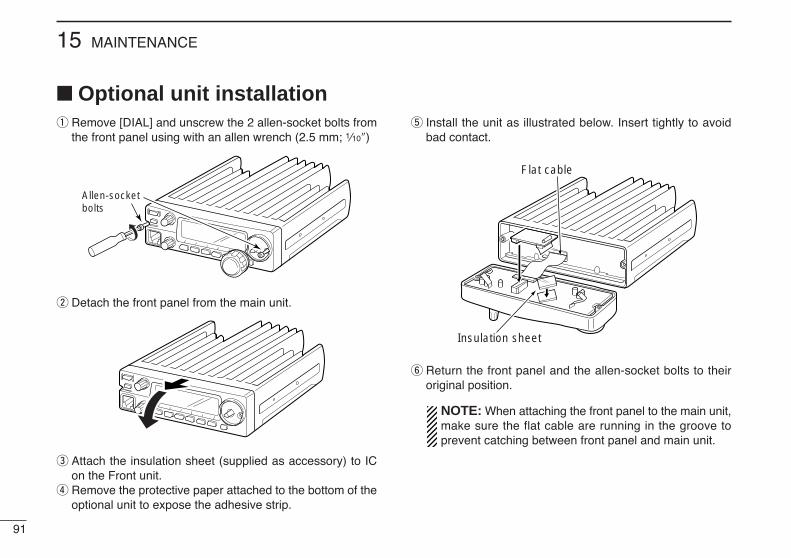
91
15 MAINTENANCE
Optional unit installationq Remove [DIAL] and unscrew the 2 allen-socket bolts from
the front panel using with an allen wrench (2.5 mm; 1⁄10″)
w Detach the front panel from the main unit.
e Attach the insulation sheet (supplied as accessory) to ICon the Front unit.
r Remove the protective paper attached to the bottom of theoptional unit to expose the adhesive strip.
t Install the unit as illustrated below. Insert tightly to avoidbad contact.
y Return the front panel and the allen-socket bolts to theiroriginal position.
NOTE: When attaching the front panel to the main unit,make sure the flat cable are running in the groove toprevent catching between front panel and main unit.
Insulation sheet
Flat cable
Allen-socketbolts
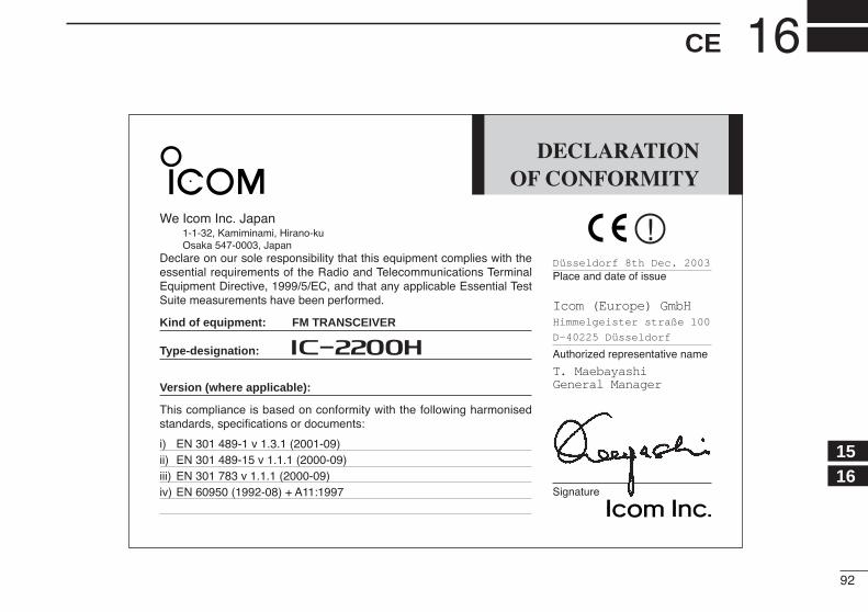
92
16CE
1516
DECLARATIONOF CONFORMITY
We Icom Inc. Japan1-1-32, Kamiminami, Hirano-kuOsaka 547-0003, Japan
Declare on our sole responsibility that this equipment complies with theessential requirements of the Radio and Telecommunications TerminalEquipment Directive, 1999/5/EC, and that any applicable Essential TestSuite measurements have been performed.
Kind of equipment: FM TRANSCEIVER
Type-designation: i2200H
Version (where applicable):
This compliance is based on conformity with the following harmonisedstandards, specifications or documents:
i) EN 301 489-1 v 1.3.1 (2001-09)ii) EN 301 489-15 v 1.1.1 (2000-09)iii) EN 301 783 v 1.1.1 (2000-09)iv) EN 60950 (1992-08) + A11:1997
Düsseldorf 8th Dec. 2003Place and date of issue
Icom (Europe) GmbHHimmelgeister straße 100
D-40225 Düsseldorf
Authorized representative name
T. MaebayashiGeneral Manager
Signature

LOCK
SETANM
MONIDUP
LOWT-SCAN
TONEPRIO
M/CALLSCAN
V/MHz
DIGITAL PRIO AO BUSYMUTENARMIDLOW
LOCKSET
ANMMONI
DUPLOW
T-SCANTONE
PRIOM/CALL
SCANV/MHz
DIGITAL PRIO AO BUSYMUTENARMIDLOW
LOCKSET
ANMMONI
DUPLOW
T-SCANTONE
PRIOM/CALL
SCANV/MHz
DIGITAL PRIO AO BUSYMUTENARMIDLOW
LOCKSET
ANMMONI
DUPLOW
T-SCANTONE
PRIOM/CALL
SCANV/MHz
DIGITAL PRIO AO BUSYMUTENARMIDLOW
LOCKSET
ANMMONI
DUPLOW
T-SCANTONE
PRIOM/CALL
SCANV/MHz
DIGITAL PRIO AO BUSYMUTENARMIDLOW
LOCKSET
ANMMONI
DUPLOW
T-SCANTONE
PRIOM/CALL
SCANV/MHz
DIGITAL PRIO AO BUSYMUTENARMIDLOW
LOCKSET
ANMMONI
DUPLOW
T-SCANTONE
PRIOM/CALL
SCANV/MHz
DIGITAL PRIO AO BUSYMUTENARMIDLOW
LOCKSET
ANMMONI
DUPLOW
T-SCANTONE
PRIOM/CALL
SCANV/MHz
DIGITAL PRIO AO BUSYMUTENARMIDLOW
DTMF MEMORY
CLONE MODE
CALL CHANNEL (p. 35)
WEATHER CHANNEL (p. 83)*2
BANK CHANNEL (p. 32)CHANNEL NAME INDICATION (p. 29)
MEMORY MODE (p. 24)
VFO mode (p. 9)
When the DTMFmemory encoder isactivated.
See p. 45 for details.
See p. 86 for details.for 1 sec.
*1Appears when accessing from memory mode only.*2Available for USA versions only.*3Appears in some version only.
ANMMONI
for 1 sec.
ANMMONI
OPTBANK
OPTBANKSCANV/MHz
PRIOM/CALL
SCANV/MHz
LOCKSET
T-SCANTONE
SCANV/MHzPRIO
M/CALL
93
MODE ARRANGEMENT17
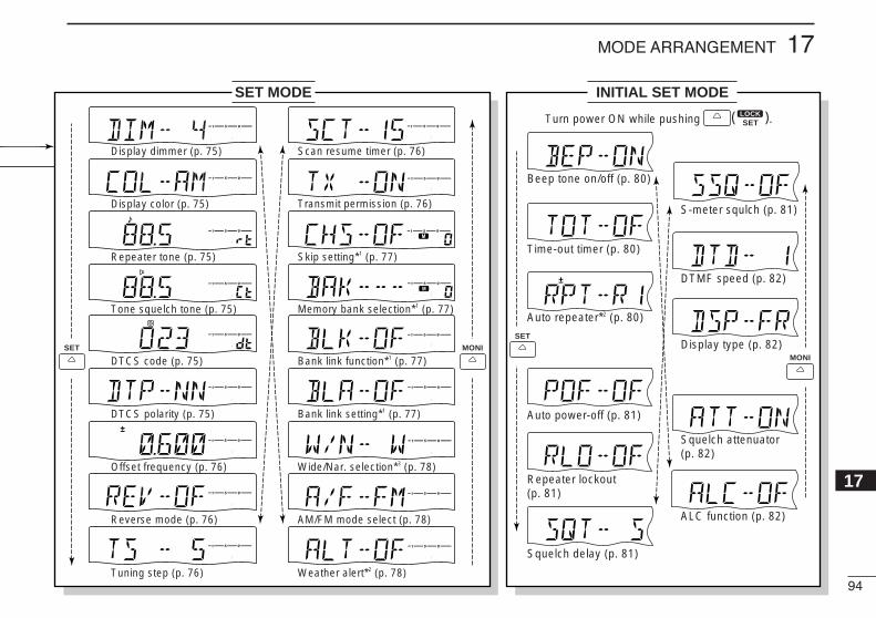
DIGITAL PRIO AO BUSY
DIGITAL PRIO AO BUSY
DIGITAL PRIO AO BUSY
DIGITAL PRIO AO BUSY
DIGITAL PRIO AO BUSY
DIGITAL PRIO AO BUSY
DIGITAL PRIO AO BUSY
DIGITAL PRIO AO BUSY
DIGITAL PRIO AO BUSY
DIGITAL PRIO AO BUSY
DIGITAL PRIO AO BUSY
DIGITAL PRIO AO BUSY
DIGITAL PRIO AO BUSY
DIGITAL PRIO AO BUSY
DIGITAL PRIO AO BUSY
DIGITAL PRIO AO BUSY
DIGITAL PRIO AO BUSY
DIGITAL PRIO AO BUSY
DIGITAL
DIGITAL
DIGITAL
DIGITAL
DIGITAL
DIGITAL
DIGITAL
DIGITAL
DIGITAL
DIGITAL
DIGITAL
SET MODE INITIAL SET MODE
Display dimmer (p. 75)
Display color (p. 75)
Repeater tone (p. 75)
Tone squelch tone (p. 75)
DTCS code (p. 75)
DTCS polarity (p. 75)
Offset frequency (p. 76)
Reverse mode (p. 76)
Tuning step (p. 76)
Scan resume timer (p. 76)
Transmit permission (p. 76)
Skip setting*1 (p. 77)
Wide/Nar. selection*3 (p. 78)
AM/FM mode select (p. 78)
Memory bank selection*1 (p. 77)
Bank link function*1 (p. 77)
Bank link setting*1 (p. 77)
Weather alert*2 (p. 78)
Turn power ON while pushing .
Beep tone on/off (p. 80)
Time-out timer (p. 80)
Auto repeater*2 (p. 80)
Auto power-off (p. 81)
Repeater lockout (p. 81)
Squelch delay (p. 81)
S-meter squlch (p. 81)
DTMF speed (p. 82)
Display type (p. 82)
Squelch attenuator (p. 82)
ALC function (p. 82)
SET MONI
SET
MONI
LOCKSET( )
94
17MODE ARRANGEMENT
17
1-1-32 Kamiminami, Hirano-ku, Osaka 547-0003, Japan
A-6329H-1EX-wPrinted in Japan© 2003–2005 Icom Inc.
<Intended Country of Use> GER FRA ESP SWE AUT NED POR DEN GBR BEL ITA FIN IRL LUX GRE SUI NOR
#02 Europe#12 Europe-1


![IC-706MKIIG Instruction Manual - ICOM Canadaicomcanada.com/products/amateur/ic-706mkiig/Amateur_IC-706MKIIG... · !4FUNCTION SSWITCHES [[F1]/[F2]/[F3] (pgs. 3, 4, 68) Push to select](https://static.fdocuments.net/doc/165x107/5c70d37809d3f2ea4d8bd95d/ic-706mkiig-instruction-manual-icom-4function-sswitches-f1f2f3-pgs.jpg)