VHDL 3 Finite State Machines FSM - cse.cuhk.edu.hkmcyang/ceng3430/vhdl_vs_verilog.pdf · primitives...
31
VHDL VS VERILOG 1 http://www.cse.cuhk.edu.hk/~mcyang/teaching.html
Transcript of VHDL 3 Finite State Machines FSM - cse.cuhk.edu.hkmcyang/ceng3430/vhdl_vs_verilog.pdf · primitives...

VHDL VS VERILOG
1
http://www.cse.cuhk.edu.hk/~mcyang/teaching.html

VHDL & Verilog
• They are both hardware description languages
for modeling hardware.
• They are each a notation to describe the
behavioral and structural aspects of an electronic
digital circuit.
2

VHDL Background
• VHSIC Hardware Description Language
• VHSIC is an abbreviation for Very High Speed
Integrated Circuit.
• Developed by the department of defense (1981)
• In 1986 rights where given to IEEE.
• Became a standard and published in 1987.
• Revised standard we know now published in 1993
(VHDL 1076-1993) regulated by VHDL international (VI).
3

VHDL Design Concept
• VHDL uses top-down approach to partition design
into small blocks (i.e., “components”)
• Entity: Describe interface signals & basic building blocks
• Architecture: Describe behavior, each entity can have
multiple Architectures
• *Configuration: Specify different architectures for a
single entity.
• The internals can change while the interface remains the same.
• It is not required to get a basic VHDL design running.
• *Package: Contain user-defined subprograms, constant
definitions, and/or type definitions to be used throughout
one or more design units.
4

Verilog Background
• Developed by Gateway Design Automation
(1980)
• Later acquired by Cadence Design(1989) who made it
public in 1990
• Became a standardized in 1995 by IEEE (Std 1364)
regulated by Open Verilog International (OVI)
5

Verilog Design Concept
• Verilog only has one building block: module
• Modules connect through their port similarly as in VHDL.
• There is only one module per file usually.
• A top level invokes instances of other modules.
• Modules can be specified behaviorally or structurally.
• Behavioral: Define behavior of digital system.
• Structural: Define hierarchical interconnection of modules.
6

HDL Modeling Capacity
7
Graph source: Douglas J. Smith, "VHDL & Verilog Compared & Contrasted Plus Modeled Example Written in VHDL, Verilog, and C"
• High-Level: VHDL is better.
• VHDL provides more features for
high-level hardware modeling.
• Such as user-defined data types,
package, configuration, library
management.
• Low-Level: Verilog is better.
• Verilog is originally created for
modeling/simulating logic gates.
• Verilog has built-in primitives or
low-level logic gates.
• Verilog supports user-defined
primitives (UDP).

IC Design Flow
8
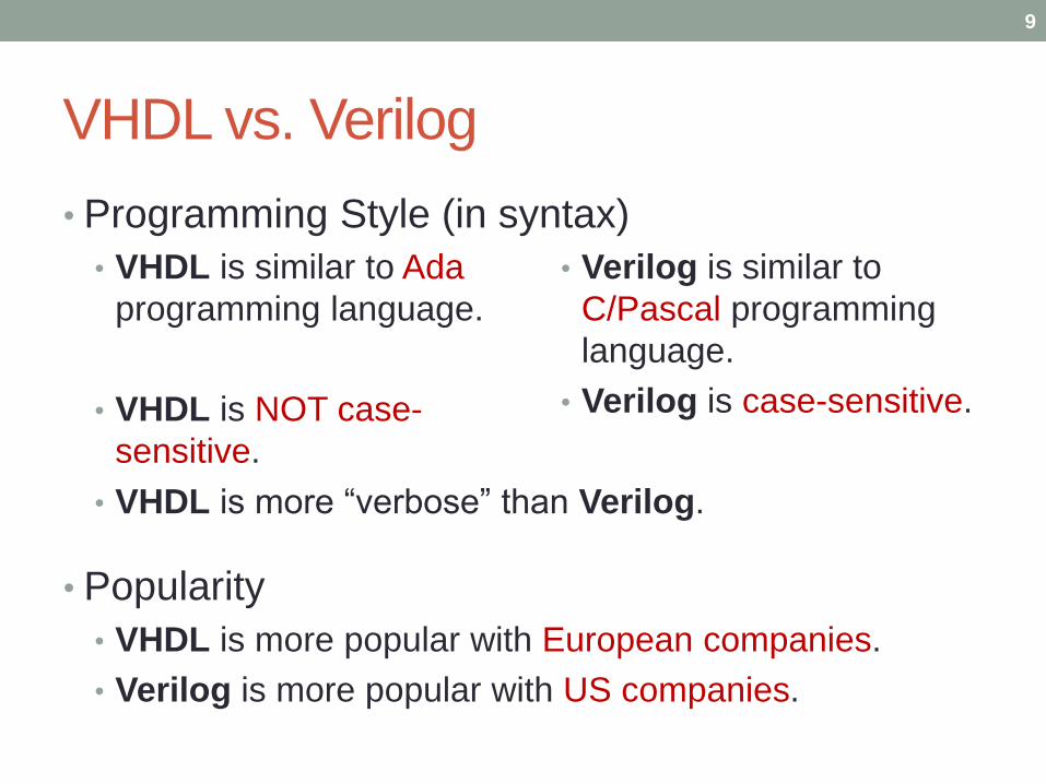
VHDL vs. Verilog
• Programming Style (in syntax)
• VHDL is more “verbose” than Verilog.
• Popularity
• VHDL is more popular with European companies.
• Verilog is more popular with US companies.
9
• VHDL is similar to Ada
programming language.
• VHDL is NOT case-
sensitive.
• Verilog is similar to
C/Pascal programming
language.
• Verilog is case-sensitive.

VHDL vs. Verilog: In details
• Overall Structure
• I/O Declaration
• Process Block
• Bus
• Signal Assignment
• Nonblocking vs Blocking Statement
• Structural Design
• Finite State Machine
• Examples
10

VHDL vs. Verilog: Overall Structure
• VHDL
Library Declaration
• library IEEE;
• …
Entity Declaration
• entity mux is
• …
• end mux
Architecture Body
• architecture arch of mux is
• begin
• …
• end arch;
• Verilog
One Module
• module mux (a,b,s,y);
• …
• endmodule
11

VHDL vs. Verilog: I/O Declaration
• VHDL• entity mux is
• port ( a,b,s: in std_logic;
• y: out std_logic);
• end mux
• architecture arch of mux is
• begin
• …
• end arch;
• Verilog• module mux (a,b,s,y);
• input a,b,s;
• output y;
• …
• endmodule
12

VHDL vs. Verilog: Process Block
• VHDL• architecture arch of mux is
• begin
• …
• process (siga, sigb)
• begin
• …
• end;
• …
• end arch;
• Verilog• module mux (a,b,s,y);
• …
• always @ (siga or sigb)
• begin
• …
• end
• …
• endmodule
•
13
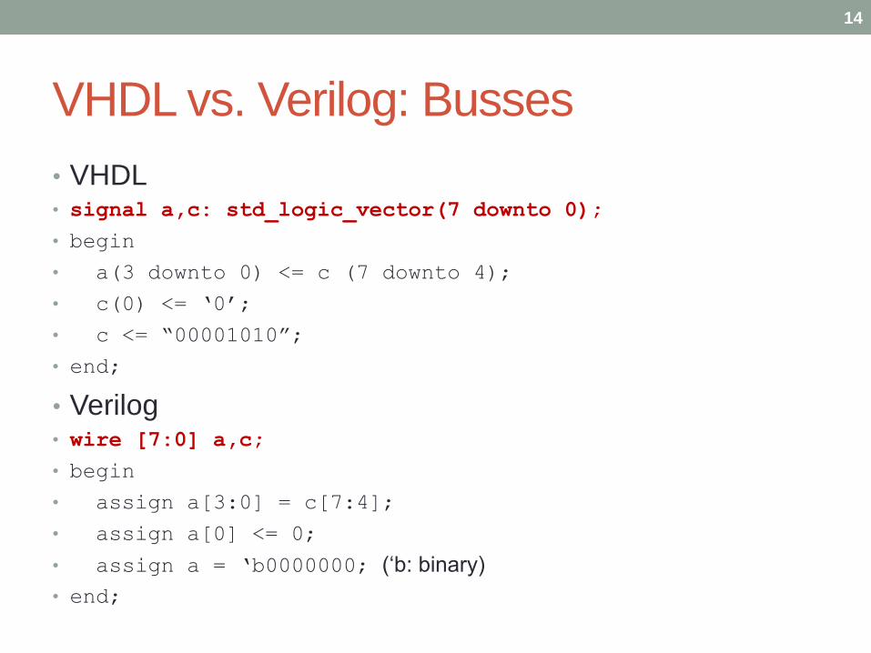
VHDL vs. Verilog: Busses
• VHDL• signal a,c: std_logic_vector(7 downto 0);
• begin
• a(3 downto 0) <= c (7 downto 4);
• c(0) <= ‘0’;
• c <= “00001010”;
• end;
• Verilog• wire [7:0] a,c;
• begin
• assign a[3:0] = c[7:4];
• assign a[0] <= 0;
• assign a = ‘b0000000; (‘b: binary)
• end;
14

VHDL vs. Verilog: Signal Assignment
• VHDL• signal a, b, c, d: std_logic;
• begin
• a <= b and c;
• d <= (c or b) xor (not (a) and b);
• end;
• Verilog• wire a,b,c,d;
• assign a = b & c;
• assign d = (c | b) ^ (~a & b);
• assign: Continual assignment to wire outside an always statement. Value of LHS is updated
when RHS changes.
15

VHDL vs. Verilog:
Nonblocking vs Blocking Assignment• Nonblocking Assignment: Schedule assignments without
blocking the procedural flow.
• Works like a signal assignment (<=) in VHDL
• In Verilog: A nonblocking assignment (<=) samples right hand side
(RHS) at beginning of timestep; with the actual assignment (LHS)
taking place at the end of the timestep.
• Blocking Assignment: Executed before the execution of
the statements in a sequential block.
• Works like a variable assignment (:=) in VHDL
• In Verilog: A blocking assignment (=) will evaluate the RHS and
perform the LHS assignment without interruption from another
Verilog statement.
16

Nonblocking Assignments in Verilog
• Should use nonblocking assignments in always blocks to
synthesize/simulate sequential logic.
• module timetest (y1,y2,a,clk);
• output y1,y2;
• input a,clk;
• reg y1,y2;
• always @(posedge clk) begin
• y1 <= a;
• y2 <= y1;
• end
• endmodule
17

Blocking Assignments in Verilog
• Use blocking assignments for always blocks that are
purely combinational.
• reg y, t1, t2;
• always @(a or b or c or d) begin
• t1 = a & b;
• t2 = c & d;
• y = t1 | t2;
• end
18

Nonblocking vs Blocking (in Verilog)
Nonblocking (Behavior Level)
• module Full_Adder( A, B, Cin,
Sum, Cout );
• input A, B, Cin;
• output Sum, Cout;
• wire W1, W2, W3;
• always @( A, B, Cin ) begin
• { Cout, Sum } = A + B + Cin;
• end
• endmodule
Blocking (Dataflow Level)
• module Full_Adder( A, B, Cin,
Sum, Cout );
• input A, B, Cin;
• output Sum, Cout;
• wire W1, W2, W3;
• assign W1 = A^B;
• assign W2 = W1&Cin;
• assign W3 = A&B;
• assign Sum = W1^Cin;
• assign Cout = W2|W3;
• endmodule
19
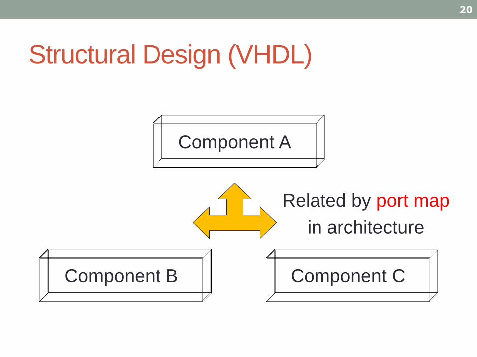
Structural Design (VHDL)
20
Component C
Related by port map
in architecture
Component B
Component A

Structural Design (VHDL)1) library IEEE;
2) use IEEE.STD_LOGIC_1164.ALL;
3) entity and2 is
4) port (a,b: in STD_LOGIC;
5) c: out STD_LOGIC );
6) end and2;
7) architecture and2_arch of and2 is
8) begin
9) c <= a and b;
10) end and2_arch;
11) -------------------------------------------
12) library IEEE;
13) use IEEE.STD_LOGIC_1164.ALL;
14) entity or2 is
15) port (a,b: in STD_LOGIC;
16) c: out STD_LOGIC );
17) end or2;
18) architecture or2_arch of or2 is
19) begin
20) c <= a or b;
21) end or2_arch;
a) library IEEE;
b) use IEEE.STD_LOGIC_1164.ALL;
c) -------------------------------------------
d) entity test is
e) port ( in1: in STD_LOGIC; in2: in STD_LOGIC;
f) in3: in STD_LOGIC;
g) out1: out STD_LOGIC );
h) end test;
i) architecture test_arch of test is
j) component and2 --create component
k) port (a,b: in std_logic; c: out std_logic);
l) end component ;
m) component or2 --create component
n) port (a,b: in std_logic; c: out std_logic);
o) end component ;
p) signal con1_signal: std_logic;
q) begin
r) label1: and2 port map (in1, in2, con1_signal);
s) label2: or2 port map (con1_signal, in3, out1);
t) end test_arch;
21

Structural Design (Verilog)
• One top module, several (sub) modules.
22
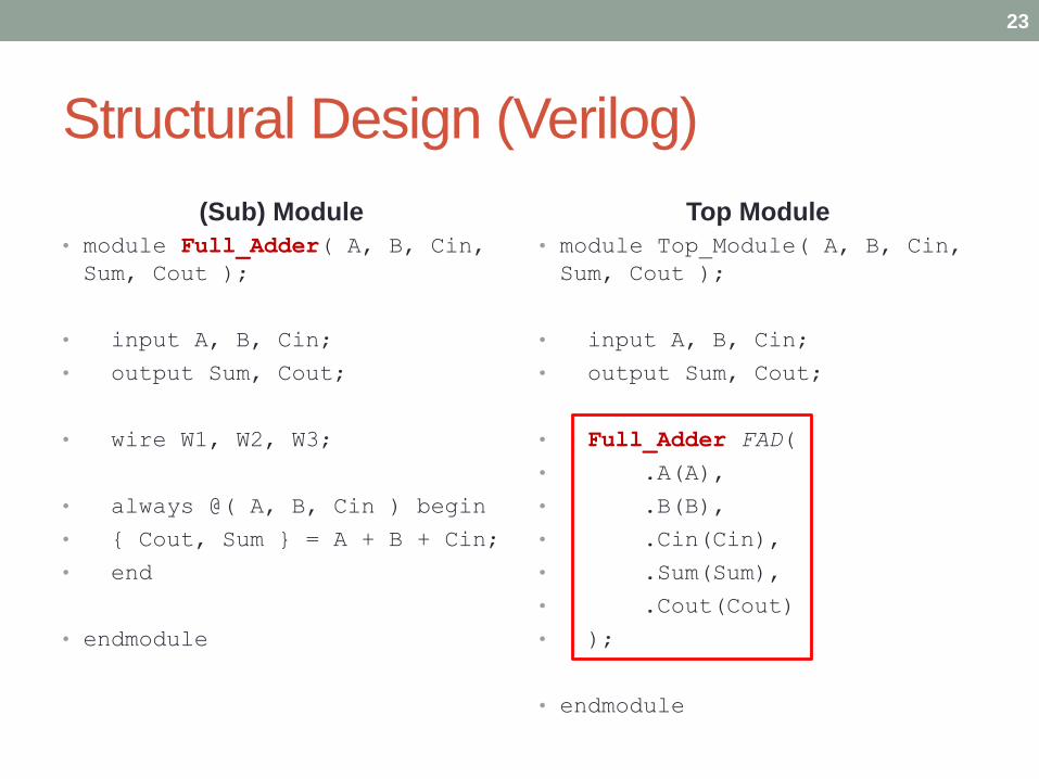
Structural Design (Verilog)
(Sub) Module
• module Full_Adder( A, B, Cin,
Sum, Cout );
• input A, B, Cin;
• output Sum, Cout;
• wire W1, W2, W3;
• always @( A, B, Cin ) begin
• { Cout, Sum } = A + B + Cin;
• end
• endmodule
Top Module
• module Top_Module( A, B, Cin,
Sum, Cout );
• input A, B, Cin;
• output Sum, Cout;
• Full_Adder FAD(
• .A(A),
• .B(B),
• .Cin(Cin),
• .Sum(Sum),
• .Cout(Cout)
• );
• endmodule
23

Finite State Machine in Verilog (1/2)
24
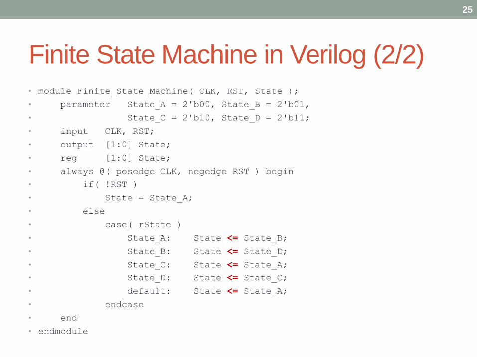
Finite State Machine in Verilog (2/2)• module Finite_State_Machine( CLK, RST, State );
• parameter State_A = 2'b00, State_B = 2'b01,
• State_C = 2'b10, State_D = 2'b11;
• input CLK, RST;
• output [1:0] State;
• reg [1:0] State;
• always @( posedge CLK, negedge RST ) begin
• if( !RST )
• State = State_A;
• else
• case( rState )
• State_A: State <= State_B;
• State_B: State <= State_D;
• State_C: State <= State_A;
• State_D: State <= State_C;
• default: State <= State_A;
• endcase
• end
• endmodule
25

VHDL• LIBRARY IEEE;
• …
• ENTITY Counter IS
• PORT( Clock, Reset,UPDOWN: IN STD_LOGIC;
• Max_count: IN STD_LOGIC_VECTOR(7 downto 0);
• Count : OUT STD_LOGIC_VECTOR(7 downto 0) );
• END Counter;
• ARCHITECTURE behaviour OF Counter IS
• SIGNAL internal_count: STD_LOGIC_VECTOR(7 downto 0);
• BEGIN
• Count <= internal_count;
• PROCESS(Reset,Clock)
• BEGIN
• IF reset='0' THEN
• internal_count<="00000000";
• ELSIF clock 'EVENT AND clock='0' THEN
• IF updown='0' THEN
• IF internal_count<Max_count THEN
• internal_count<=internal_count+1;
• ELSE
• internal_count<="00000000";
• END IF;
• ELSIF updown='1' THEN
• IF "00000000"<internal_count THEN
• internal_count<=internal_count-1;
• ELSE
• internal_count<=Max_count;
• END IF;
• END IF;
• END IF;
• END PROCESS;
• END behaviour;
26
Verilog• MODULE counter (updown,clock,reset,MaxCount,Count);
• output[7:0] Count;
• input[7:0] MaxCount;
• input clock, reset, updown;
• reg[7:0] Cnt;
• assign Count=Cnt;
• ALWAYS@(negedge clock or negedge reset)
• begin
• if(~reset)
• Cnt=8'b0000_0000;
• else if(updown)
• if (Cnt<MaxCount)
• Cnt=Count+1;
• else
• Cnt=8'b0000_0000;
• else if(~updown)
• if (8'b0000_0000<Cnt)
• Cnt=Cnt-1;
• else
• Cnt=MaxCount;
• end
• ENDMODULE
Working Example: Counter
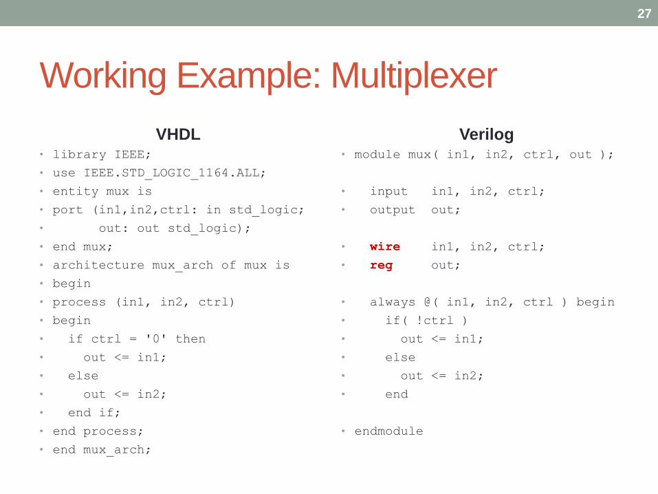
Working Example: Multiplexer
VHDL• library IEEE;
• use IEEE.STD_LOGIC_1164.ALL;
• entity mux is
• port (in1,in2,ctrl: in std_logic;
• out: out std_logic);
• end mux;
• architecture mux_arch of mux is
• begin
• process (in1, in2, ctrl)
• begin
• if ctrl = '0' then
• out <= in1;
• else
• out <= in2;
• end if;
• end process;
• end mux_arch;
Verilog• module mux( in1, in2, ctrl, out );
• input in1, in2, ctrl;
• output out;
• wire in1, in2, ctrl;
• reg out;
• always @( in1, in2, ctrl ) begin
• if( !ctrl )
• out <= in1;
• else
• out <= in2;
• end
• endmodule
27

Wire vs. Register in Verilog (1/2)
• Wire: Has no memory
• Physical wire in the circuit
• A wire does not store its value, it must be driven by
• connecting the wire to the output of a gate or module
• assigning a value to the wire in a continuous assignment
• Cannot use “wire” in left-hand-side of assignment in procedural block.
• Register: Has memory
• Not “register” of CPU
• No guarantee to be a DFF (D-flip flop)
• Maybe a physical wire
• Holding its value until a new value is assigned to it (event-driven).
• Cannot use “reg” in left-hand side of continuous assignment.
28

Wire vs. Register in Verilog (2/2)
29

Conclusion
• Verilog and VHDL are equivalent for RTL modeling.
• For high level behavioral modeling, VHDL is better.
• Verilog does not have ability to define new data types
• Other missing features for high level modeling
• Verilog has built-in gate level and transistor level
primitives.
• Verilog much better than VHDL at below the RTL level.
• Bottom Line: You should know both!!!
30
References
• VHDL & Verilog Compared & Contrasted - Plus Modeled
Example Written in VHDL, Verilog and C.
• Verilog vs VHDL: Explain by Examples
• Verilog VS VHDL (By Kurt Leyba)
• Verilog VHDL vs. Verilog – MWFTR
• Verilog Tutorial (Chao-Hsien, Hsu)
• https://hom-wang.gitbooks.io/verilog-
hdl/content/index.html
31