vFBD35 - Ruskin
4
Spec VFBD35-818/Replaces VFBD35-708 © Ruskin August 2018 www.ruskin.com • 3900 Dr. Greaves Rd. • Kansas City, MO 64030 • (816) 761-7476 VFBD35 IRIS BALANCINg DAMpER Ruskin IRIS Balancing Damper model VFBD35 is an excellent solu- tion for airflow measurement, balance and control at branch takeoff and exhaust locations. It provides fast and accurate measurement for office buildings, schools, pharmaceuticals, clean room environments and laboratories. Since measurement and control are accomplished at the same loca- tion, initial installation and commissioning time is reduced dramati- cally. The IRIS damper is perfect for applications requiring air balance on a regular basis. FEATURES • Factory calibrated for precise airflow measurement • Single station measurement and control • Blades fully retract into frame for duct cleaning • Reduced installation and balancing labor time • Linear response flow control DIMENSIONS IN INChES DIAMETER 4" (102) 5" (127) 6" (152) 8" (203) 10" (254) 12" (305) 16" (406) 20" (508) 25” (635) 32 " (813) 1.2 1.2 1.2 1.2 1.6 1.6 2.4 2.0 2.0 3.9 0.6 0.6 0.6 0.6 0.7 0.7 0.8 0.8 0.9 0.9 3.9 4.9 5.9 7.8 9.8 11.8 15.7 19.6 24.7 31.4 4.6 4.6 4.6 4.6 5.3 6.1 7.5 6.7 6.7 10.6 6.5 7.4 9.1 11.2 13.2 16.1 20.7 25.8 32.1 40.0 1.1 1.5 2.0 3.1 4.6 7.7 14.1 21.2 34.4 55.1 A C D L OD WT (lbs) D A C A L OD STANDARD CONSTRUCTION FRAME 22 gauge (.759) galvanized steel. BLADE SEgMENTS 22 gauge (.759) galvanized steel. SEAL Full circumference neoprene. CASINg LEAkAgE 6 CFM (170 l/s) Max. AIR pRESSURE TApS Plastic with integral plastic caps. ACCURACY ±5% CApACITIES 15 cfm (425 l/s) to 20,000 cfm (566337 l/s) FINISh Mill DAMpER SIZES 4, 5, 6, 8, 10, 12, 16, 20, 25 & 32 (102, 127, 152, 203, 254, 305, 406, 508, 635, and 813). TEMpERATURE RANgE 32°F (0°C) – 180°F (82°C) Continuous 250°F (121°C) Intermittent (stainless option) VARIATIONS • Stainless Steel Frame & Blades • AMS810 Pressure Transducer • Positive Seal NOTE: Dimensions shown in parentheses ( ) indicate millimeters.
Transcript of vFBD35 - Ruskin

Spec vFBD35-818/Replaces VFBD35-708 © Ruskin August 2018
www.ruskin.com • 3900 Dr. Greaves Rd. • Kansas City, MO 64030 • (816) 761-7476
vFBD35IRIS BALANCINg DAMpER
Ruskin IRIS Balancing Damper model VFBD35 is an excellent solu-tion for airflow measurement, balance and control at branch takeoffand exhaust locations. It provides fast and accurate measurement foroffice buildings, schools, pharmaceuticals, clean room environmentsand laboratories.
Since measurement and control are accomplished at the same loca-tion, initial installation and commissioning time is reduced dramati-cally. The IRIS damper is perfect for applications requiring air balanceon a regular basis.
FEATURES• Factory calibrated for precise airflow measurement• Single station measurement and control• Blades fully retract into frame for duct cleaning• Reduced installation and balancing labor time• Linear response flow control
DIMENSIONS IN INChESDIAMETER4" (102)5" (127)6" (152)8" (203)10" (254)12" (305)16" (406)20" (508)25” (635)32 " (813)
1.21.21.21.21.61.62.42.02.03.9
0.60.60.60.60.70.70.80.80.90.9
3.94.95.97.89.811.815.719.624.731.4
4.64.64.64.65.36.17.56.76.710.6
6.57.49.111.213.216.120.725.832.140.0
1.11.52.03.14.67.714.121.234.455.1
A C D L OD WT (lbs)
D
A C AL OD
STANDARD CONSTRUCTIONFRAME
22 gauge (.759) galvanized steel.BLADE SEgMENTS
22 gauge (.759) galvanized steel.SEAL
Full circumference neoprene.CASINg LEAkAgE
6 CFM (170 l/s) Max.AIR pRESSURE TApS
Plastic with integral plastic caps.ACCURACy
±5%CApACITIES
15 cfm (425 l/s) to 20,000 cfm (566337 l/s)FINISh
MillDAMpER SIzES
4, 5, 6, 8, 10, 12, 16, 20, 25 & 32 (102, 127, 152, 203, 254, 305,406, 508, 635, and 813).
TEMpERATURE RANgE32°F (0°C) – 180°F (82°C) Continuous250°F (121°C) Intermittent (stainless option)
vARIATIONS• Stainless Steel Frame & Blades• AMS810 Pressure Transducer• Positive Seal
NOTE: Dimensions shown in parentheses ( ) indicate millimeters.
Damper position2.00
1.50
1.00
0.50
0.30
0.20
0.10
0.050.04
0.40
0.03
0.0210 15 20 30 40 50 60 80 100 150 200 250
q, cfm
1
2
345678
K=34
8K=
251K=
201
K=15
1
K=11
4
K=84
K=57
K=30
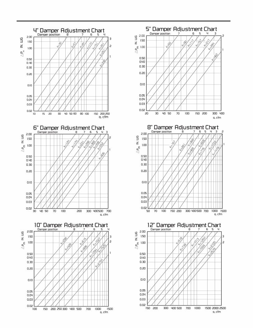
4” Damper Adjustment Chart
P mIN
. WG
q, cfm
2.004567
K=15
7
K=11
7
5” Damper Adjustment ChartDamper position
P mIN
. WG
K=21
7
K=90
K=29
4K=
462
32
1
1.50
1.00
0.500.40
0.30
0.20
0.10
0.050.04
0.03
0.0220 30 40 50 70 100 150 200 300 400
K=50
q, cfm
2.004567
K=29
8
K=23
1
6” Damper Adjustment ChartDamper position
P mIN
. WG
K=36
8
K=17
4
K=44
8K=
806
3
2
1
1.50
1.00
0.500.40
0.30
0.20
0.10
0.050.04
0.03
0.0270030 40 50 70 100 500200 300 400
K=12
4
8
K=55
2
q, cfm
2.004567
K=60
9
K=46
8
8” Damper Adjustment ChartDamper position
P mIN
. WG
K=77
6
K=36
8
K=16
7
K=14
78
3 2
11.00
1.50
0.500.40
0.30
0.20
0.10
0.050.04
0.03
0.02700150 100050 70 100 500200 300 400
K=28
1
8
K=10
331500
q, cfm
2.004567
K=102
7
K=806
10” Damper Adjustment ChartDamper position
P mIN
. WG
K=129
4
K=61
5
K=29
8
K=21
54
3
2
1
1.00
1.50
0.500.40
0.30
0.20
0.10
0.050.04
0.03
0.02700150 1000250100 500200 300 400
K=428
8
K=152
5
1500q, cfm
2.004567
K=12
54
K=10
13
12” Damper Adjustment ChartDamper position
P mIN
. WG
K=15
59
K=73
9K=51
8
K=25
79
3
2
1.50
1.00
0.500.400.30
0.20
0.10
0.050.04
0.03
0.02700 1000150 500200 300 400
8
K=21
00
1500 2000 2500

q, cfm
2.004567
K=22
51
K=17
63
16” Damper Adjustment ChartDamper position
P mIN
. WG
K=29
53K=12
88
K=51
8
K=43
81
3 2
11.50
1.00
0.500.40
0.30
0.20
0.10
0.050.04
0.03
0.02400030001000150 2000500200 300 400
K=95
0
8
K=34
11
5000q, cfm
2.004567
K=37
46
K=29
60
20” Damper Adjustment ChartDamper position
P mIN
. WG
K=48
83
K=22
27
K=10
03
K=76
93
32
11.50
1.00
0.500.40
0.30
0.20
0.10
0.050.04
0.03
0.02700 5000300 400 500 40001000 2000 3000
K=16
05
8
K=59
20
8000
q, cfm
2.004567
K=56
52
K=42
48
25” Damper Adjustment ChartDamper position
P mIN
. WG
K=79
60
K=30
64
K=11
74
K=15
084
3 2
1
1.50
1.00
0.500.40
0.30
0.20
0.10
0.050.04
0.03
0.0210000400 600 1000 50002000 3000
K=21
00
8
K=99
33
16000q, cfm
2.004567
K=72
58K=
5686
32” Damper Adjustment ChartDamper position
P mIN
. WG
K=89
30K=
1344
5K=24
65
K=16
355
3
2
1
1.50
1.00
0.500.40
0.30
0.20
0.10
0.050.04
0.03
0.022000 10000700 1000 1500 50003000 4000
K=40
80
8
K=11
505
15000
SUggESTED SpECIFICATIONFurnish and install, at locations shown on plans or in accordancewith schedules, calibrated IRIS balancing dampers. IRIS damperframe shall be 22 gage steel or 316 stainless (as called for onschedules). Frame shall fully encapsulate IRIS blade segments,holding them firmly into position, and have rolled mounting beads toincrease the overall strength of the assembly. Full circumferenceduct seal shall be furnished on the air entering and air leaving sideof the frame to insure a tight duct connection. Casing leakage shallnot exceed 6 cfm. IRIS blade segments shall be internally linked anddriven by a factory calibrated manual adjustment knob. All linkageparts shall be fully encapsulated and out of the air stream for years
of dependable, maintenance-free operation. Manual adjustmentknob shall be calibrated to the exact aperture position and alignedwith the K factor set point to provide linear response flow control.Flow measurement shall be +/- 5%. Assembled units shall be fur-nished with specific charts designed for the exact size and bladeaperture configuration. Air pressure taps shall be integral to thedamper frame and positioned on either side of the IRIS blade seg-ments. The damper shall have minimal self-generated noise char-acteristics as detailed on published sound data to be included withsubmittals. Damper in all respects shall be equivalent to RuskinModel VFBD35.
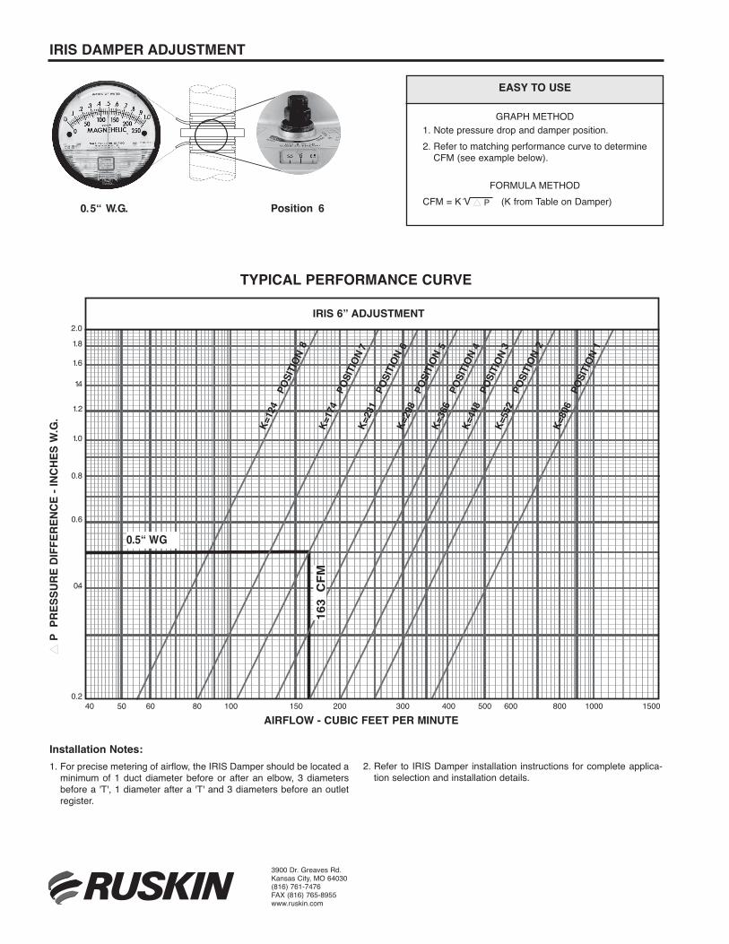
IRIS DAMpER ADjUSTMENT
0.5“ W.G. Position 6
Installation Notes:1. For precise metering of airflow, the IRIS Damper should be located a
minimum of 1 duct diameter before or after an elbow, 3 diametersbefore a 'T', 1 diameter after a 'T' and 3 diameters before an outletregister.
2. Refer to IRIS Damper installation instructions for complete applica-tion selection and installation details.
3900 Dr. Greaves Rd.Kansas City, MO 64030(816) 761-7476FAX (816) 765-8955www.ruskin.com
EASy TO USE
GRAPH METHOD1. Note pressure drop and damper position.2. Refer to matching performance curve to determine
CFM (see example below).
FORMULA METHODCFM = K V � P (K from Table on Damper)better
byAIRFLOW
DESIGN™
0.5“ WG
163
CFM
IRIS-M 6” ADJUSTMENT
AIRFLOW - CUBIC FEET PER MINUTE
P P
RES
S UR
E D
IFFE
RE N
CE
- IN
CH
ES W
.G
2.0
Typical Performance CurveK=
124
POS
ITION
8K=
174
POS
ITION
7K=
231
POS
ITION
6K=
298
POS
ITION
5K=
366
POS
ITION
4K=
448
POS
ITION
3K=
552
POS
ITION
2K=
806
POS
ITION
11.8
1.6
1.4
1.2
1.0
0.8
0.6
0.4
0.240 50 60 80 100 150 200 300 400 500 600 800 1000 1500
TypICAL pERFORMANCE CURvE
IRIS 6” ADjUSTMENT
AIRFLOW - CUBIC FEET pER MINUTE
� p
pRE
SSUR
E DI
FFER
ENCE
- IN
ChES
W.g
.