Vessel Technical Specifications
145
Bay Breeze and Solano Replacement Vessels 19-013 Vessel Technical Specifications 20 April 2020 Revision - SAN FRANCISCO BAY AREA
Transcript of Vessel Technical Specifications

Bay Breeze and Solano Replacement Vessels 19-013
Vessel Technical Specifications 20 April 2020 Revision -
SAN FRANCISCO BAY AREA

PART B - TECHNICAL SPECIFICATION Bay Breeze & Solano Replacement Vessels
TABLE OF CONTENTS 19-013
Part B - Table of Contents Page 1
14682153.1
TABLE OF CONTENTS 000 General Requirements ............................................................................................................................. 6
020 PURPOSE ............................................................................................................................................... 6
030 OWNER’S REQUIREMENTS VS. OWNER’S PREFERENCES ...................................................................... 6
040 OVERVIEW ............................................................................................................................................. 6
050 MISSION ................................................................................................................................................ 7
060 OPERATIONAL REQUIREMENTS ............................................................................................................ 7
061 ROUTE(S) ............................................................................................................................................... 7
062 LOAD PROFILES ................................................................................................................................... 11
063 LOADING/OFFLOADING ...................................................................................................................... 12
064 LOADING FACILITIES FOR PASSENGERS .............................................................................................. 12
065 WAKE WASH AND SPEED RESTRICTIONS ............................................................................................ 12
066 START UP AND SHUTDOWN ................................................................................................................ 13
070 ENVIRONMENTAL CONDITIONS .......................................................................................................... 13
080 VESSEL REQUIREMENTS ...................................................................................................................... 14
081 PRINCIPAL CHARACTERISTICS ............................................................................................................. 15
082 SPEED .................................................................................................................................................. 15
083 APPEARANCE ....................................................................................................................................... 16
084 PAYLOAD/CAPACITIES ......................................................................................................................... 16
085 CREW ................................................................................................................................................... 16
086 SEAKEEPING & MANEUVERING .......................................................................................................... 16
087 MAINTAINABILITY ............................................................................................................................... 16
088 NOISE AND VIBRATION ....................................................................................................................... 17
089 EMISSIONS .......................................................................................................................................... 19
090 VESSEL REGULATORY REQUIREMENTS ............................................................................................... 19
091 REGULATORY ....................................................................................................................................... 19
092 ACCOMMODATIONS FOR PASSENGERS WITH DISABILITIES ............................................................... 20
100 Structure ................................................................................................................................................ 21
101 STRUCTURAL MATERIALS .................................................................................................................... 21
102 WELDING AND FITTING ....................................................................................................................... 22
111 HULL STRUCTURE ................................................................................................................................ 22
126 TANKS .................................................................................................................................................. 23
151 SUPERSTRUCTURE .............................................................................................................................. 24
163 SEACHEST ............................................................................................................................................ 24
167 HULL DOORS, HATCHES AND MANHOLES .......................................................................................... 25

PART B - TECHNICAL SPECIFICATION Bay Breeze & Solano Replacement Vessels
TABLE OF CONTENTS 19-013
Part B - Table of Contents Page 2
14682153.1
171 MASTS ................................................................................................................................................. 25
200 Machinery - Propulsion and Ship Service .............................................................................................. 26
205 PROPULSION SYSTEM INTEGRATION .................................................................................................. 27
233 DIESEL ENGINES .................................................................................................................................. 27
233 REDUCTION GEARS .............................................................................................................................. 28
241 PROPULSION COUPLINGS.................................................................................................................... 29
243 SHAFTING ............................................................................................................................................ 29
244 SEALS ................................................................................................................................................... 31
247 WATERJETS.......................................................................................................................................... 31
251 COMBUSTION AIR SYSTEM ................................................................................................................. 31
252 PROPULSION CONTROL SYSTEM ......................................................................................................... 32
256 SEAWATER COOLING .......................................................................................................................... 33
259 ENGINE EXHAUST ................................................................................................................................ 33
261 FUEL OIL SYSTEM ................................................................................................................................ 35
262 LUBE OIL SYSTEM ................................................................................................................................ 36
298 OPERATING FLUIDS ............................................................................................................................. 36
300 Electrical Systems .................................................................................................................................. 37
301 ELECTRICAL LOAD ANALYSIS ............................................................................................................... 37
302 ELECTRICAL MOTORS .......................................................................................................................... 37
303 ELECTRICAL MOTOR CONTROLLERS .................................................................................................... 37
305 NAMEPLATES AND LABELS – ELECTRICAL EQUIPMENT ...................................................................... 38
311 ELECTRICAL SYSTEMS - GENERATING ................................................................................................. 38
313 BATTERY SYSTEMS .............................................................................................................................. 39
314 POWER CONVERSION EQUIPMENT .................................................................................................... 39
321 CABLES & CABLE INSTALLATION ......................................................................................................... 40
322 SHORE POWER CONNECTION ............................................................................................................. 40
324 ELECTRICAL SYSTEMS - SWITCHBOARDS ............................................................................................ 41
331 ELECTRICAL SYSTEMS - DISTRIBUTION ................................................................................................ 41
332 ELECTRICAL SYSTEMS - LIGHTING ....................................................................................................... 41
400 Command and Monitoring .................................................................................................................... 45
401 PILOTHOUSE & CONSOLE ARRANGEMENT ......................................................................................... 45
413 WIFI .................................................................................................................................................... 48
421 NAVIGATION & SIGNALING EQUIPMENT ........................................................................................... 48
422 NAVIGATION LIGHTS ........................................................................................................................... 48
423 NAVIGATION ELECTRONICS ................................................................................................................ 49

PART B - TECHNICAL SPECIFICATION Bay Breeze & Solano Replacement Vessels
TABLE OF CONTENTS 19-013
Part B - Table of Contents Page 3
14682153.1
432 TELEPHONE SYSTEM ........................................................................................................................... 49
433 PUBLIC ADDRESS & MESSAGING SYSTEM ........................................................................................... 50
436 GENERAL & FIRE ALARM SYSTEM ....................................................................................................... 51
438 ALARM SYSTEM ................................................................................................................................... 51
439 CCTV SURVEILLANCE SYSTEM ............................................................................................................. 53
441 RADIOS ................................................................................................................................................ 54
443 DECK LOUDHAILER .............................................................................................................................. 54
444 WHISTLE .............................................................................................................................................. 54
448 VIDEO SYSTEM .................................................................................................................................... 54
451 GLOBAL POSITIONING SYSTEM (GPS) AND ELECTRONIC CHARTING SYSTEM (ECS) ........................... 54
455 AUTOMATIC IDENTIFICATION SYSTEM (AIS) ....................................................................................... 55
465 DEPTH SOUNDER ................................................................................................................................ 55
500 Auxiliary Systems ................................................................................................................................... 56
505 GENERAL PIPING REQUIREMENTS ...................................................................................................... 56
506 VENTS, FILLS, AND SOUNDING SYSTEMS ............................................................................................ 56
507 PIPING DESIGNATION & MARKINGS ................................................................................................... 58
514 HEATING, VENTILATION, & AIR CONDITIONING (HVAC) .................................................................... 58
524 AUXILIARY SEA WATER COOLING SYSTEMS ........................................................................................ 59
526 DRAINS ................................................................................................................................................ 60
528 SEWAGE SYSTEM................................................................................................................................. 60
529 BILGE AND FIRE SYSTEM ..................................................................................................................... 60
533 POTABLE AND FRESH WATER SYSTEMS .............................................................................................. 61
555 FIRE SUPPRESSION SYSTEMS .............................................................................................................. 61
581 GROUND TACKLE ................................................................................................................................. 62
582 MOORING ........................................................................................................................................... 62
583 LIFESAVING EQUIPMENT .................................................................................................................... 63
600 Outfitting ................................................................................................................................................ 64
601 GENERAL ARRANGEMENT ................................................................................................................... 64
602 HULL DESIGNATING & MARKING ........................................................................................................ 64
603 DRAFT MARKS ..................................................................................................................................... 65
604 LOCKS, KEYS, & TAGS .......................................................................................................................... 65
612 RAILS, STANCHIONS, & LIFELINES ....................................................................................................... 66
621 NON-STRUCTURAL BULKHEADS .......................................................................................................... 66
622 FLOOR PLATES & GRATINGS ............................................................................................................... 67
623 LADDERS AND STAIRS ......................................................................................................................... 67

PART B - TECHNICAL SPECIFICATION Bay Breeze & Solano Replacement Vessels
TABLE OF CONTENTS 19-013
Part B - Table of Contents Page 4
14682153.1
624 NON-STRUCTURAL CLOSURES ............................................................................................................ 67
625 AIRPORTS, FIXED PORT LIGHTS, & WINDOWS .................................................................................... 68
626 WINDOW WIPERS ............................................................................................................................... 68
631 PAINT & COATINGS ............................................................................................................................. 68
631.1 PAINT & COATINGS OPTION ............................................................................................................... 71
633 CATHODIC PROTECTION ..................................................................................................................... 71
634 DECK COVERING .................................................................................................................................. 72
635 INSULATION ........................................................................................................................................ 72
644 SANITARY SPACES & FIXTURES ........................................................................................................... 73
645 INTERIOR OUTFITTING ........................................................................................................................ 74
651 COMMISSARY SPACES ......................................................................................................................... 75
654 UTILITY SPACES ................................................................................................................................... 78
656 TRASH DISPOSAL SPACES .................................................................................................................... 78
671 LOCKERS & SPECIAL STOWAGE ........................................................................................................... 78
672 BICYCLE ACCESS AND STOWAGE......................................................................................................... 79
800 Management and Engineering .............................................................................................................. 80
810 DESIGN & ENGINEERING ..................................................................................................................... 80
820 TECHNICAL DOCUMENTS .................................................................................................................... 82
830 MATERIALS .......................................................................................................................................... 83
835 DRYDOCKING ...................................................................................................................................... 86
836 PRELIMINARY ACCEPTANCE, SURVEY & TRIALS .................................................................................. 86
837 FINAL ACCEPTANCE, SURVEY & TRIALS ............................................................................................... 88
840 QUALITY ASSURANCE AND INSPECTION OF WORK AT CONTRACTOR’S SITE ..................................... 89
840.1 FACTORY ACCEPTANCE TESTING ........................................................................................................ 90
841 TESTING AND TRIALS REQUIREMENTS ................................................................................................ 90
841.1 TRIALS CONDITION .............................................................................................................................. 91
842 TRAINING ............................................................................................................................................ 91
860 WARRANTY ......................................................................................................................................... 91
900 Shipyard Contract Services .................................................................................................................... 94
901 SCOPE AND INTENT OF CONTRACT ..................................................................................................... 94
902 PROSECUTION AND PROGRESS ........................................................................................................... 94
910 MANAGEMENT REVIEW & PROGRESS MEETINGS .............................................................................. 94
921 PROJECT SCHEDULE ............................................................................................................................ 95
922 SCHEDULE REQUIREMENTS ................................................................................................................ 96
923 SCHEDULE UPDATES ........................................................................................................................... 96

PART B - TECHNICAL SPECIFICATION Bay Breeze & Solano Replacement Vessels
TABLE OF CONTENTS 19-013
Part B - Table of Contents Page 5
14682153.1
924 SCHEDULE REVISIONS ......................................................................................................................... 97
925 DELIVERABLE SCHEDULE ..................................................................................................................... 97
931 OWNER APPROVAL OF WORK ............................................................................................................ 98
930.1 REGULATORY BODY REVIEW, APPROVAL AND CERTIFICATION OF WORK ......................................... 98
932 CONFORMITY WITH CONTRACT .......................................................................................................... 99
933 COOPERATION BY CONTRACTOR ........................................................................................................ 99
934 DUTIES OF THE OWNER’S INSPECTORS .............................................................................................. 99
936 REMOVAL OF UNACCEPTABLE AND UNAUTHORIZED WORK ............................................................. 99
941 CONTRACT TIME DEFINITION ............................................................................................................ 100
942 EXTENSION OF CONTRACT TIME ....................................................................................................... 100
943 SUSPENSION OF CONTRACT TIME .................................................................................................... 101
944 SUSPENSIONS OF WORK ORDERED BY THE OWNER ........................................................................ 101
945 FAILURE TO DELIVER ON TIME .......................................................................................................... 102
946 TIME IMPACT ANALYSIS .................................................................................................................... 102
951 FINAL CLEAN-UP ................................................................................................................................ 102
952 COMPLETION OF WARRANTY PERIOD .............................................................................................. 103
953 SEQUENCE OF EVENTS LEADING TO FINAL ACCEPTANCE OF VESSEL ............................................... 103
970 SPARE PARTS ..................................................................................................................................... 104
981 PROTECTION AND RESTORATION OF PROPERTY .............................................................................. 105
981.1 CHARACTER OF WORKERS, METHODS AND EQUIPMENT ................................................................ 105
982 TRIALS ............................................................................................................................................... 106
982.1 DOCK TRIALS ..................................................................................................................................... 106
982.2 SEA TRIALS ........................................................................................................................................ 108
983 DELIVERY ........................................................................................................................................... 109
993 MATERIAL HANDLING & REMOVAL .................................................................................................. 110
Appendix B1 Shoreside Interfaces ............................................................................................................. 111
Appendix B2 WETA STD Details .................................................................................................................. 111
Appendix B3 Interior Outfitting .................................................................................................................. 111
Appendix B4 Master Equipment List .......................................................................................................... 111
Appendix B5 Mooring Interface ................................................................................................................. 111
Appendix B6 Signage .................................................................................................................................. 111
Appendix B7 Exterior Graphics ................................................................................................................... 111

PART B - TECHNICAL SPECIFICATION Bay Breeze & Solano Replacement Vessels
TECHNICAL SPECIFICATION 19-013
Part B - Technical Specifications Page 6
000 GENERAL REQUIREMENTS
020 PURPOSE
The OWNER has requested a qualified shipyard (“CONTR”) to design, construct and deliver two (2) passenger-only ferry vessel ("Vessel") with an option for one additional vessel for operation in the San Francisco Bay Area.
030 OWNER’S REQUIREMENTS VS. OWNER’S PREFERENCES
The purpose of the OWNER’s Requirements and Preferences is to convey to the CONTR what features and attributes the OWNER seeks in the new Vessel. The CONTR should incorporate these preferences, to the greatest extent possible, into the execution of the contract.
Certain performance requirements and technical aspects of the design are considered critical and absolute. These shall be referred to as the OWNER’S REQUIREMENTS. These requirements are of the highest priority to the OWNER and shall be met to the fullest extent possible, without compromise.
Maintaining commonality across the vessels in the OWNER’s fleet is very desirable as it minimizes training requirements and standardizes maintenance and spare parts inventories while minimizing downtime. These common features, equipment and configurations are referred to as the OWNER’S PREFERENCES. While not absolute requirements, the desired features described in this document are being provided to assist the CONTR with proposing a Vessel that will integrate with the existing fleet.
For the purpose of this document, OWNER’s Requirements are generally preceded by the word “shall” or presented in tabular form. Wherever an equipment manufacturer and/or model number is provided it will be deemed an OWNER Preference.
040 OVERVIEW
The OWNER requires a turn-key Vessel fully complete in every regard, built in compliance with applicable regulatory requirements, inspected and documented by the U.S. Coast Guard and ready for passenger service. The design of the vessel during the modeling and drawing process shall be reviewed and approved by the OWNER prior to construction. Reference section 810 for design engineering requirements.
Two (2) passenger only 46 CFR Subchapter “K” catamaran designed and constructed for efficient and reliable ferry service multiple existing and future routes on the San Francisco bay. The vessel is not intended as the primary vessel on any specific route, rather as an alternate vessel that is able to be employed as needed to service any of the designated routes.
In general, the OWNER is seeking a Vessel based on a proven design or parent craft. The overall emphasis should be on functional utility, high quality construction detailing, passenger comfort, ease of maintenance, ease of repair and longevity. High technology systems and equipment containing levels of control and automation that exceed regulatory requirements are neither required nor desired. The Vessel shall contain simple, well-proven, robust equipment and control systems. Vessel start-up procedures are to be based on a single operator preforming all daily system checks and tasks within fifteen (15) minutes. Port and starboard hulls should have equipment and system layouts as similar as possible.
The CONTR shall be responsible for developing the design solutions and details consistent with the Technical Specifications and other requirements of the contract, including but not limited to, the identification, provision and

PART B - TECHNICAL SPECIFICATION Bay Breeze & Solano Replacement Vessels
TECHNICAL SPECIFICATION 19-013
Part B - Technical Specifications Page 7
installation of all necessary materials and obtaining all regulatory approvals and certifications. The CONTR shall utilize proven marine technology.
The new vessel shall be constructed and finished to the same high standard of recent WETA newbuilds such as the HYDRUS and PYXIS class vessels and recent refits such as the GEMINI class vessels.
Where no particular preference is stated, the CONTR should offer its best standard equipment and installation when considering regulatory requirements, good marine practice, past experience and quality.
050 MISSION
The Vessel shall be operated as a commuter ferry that will serve a varied clientele including local residents and tourists. The primary mission of the vessel is to provide safe, efficient, reliable and comfortable transportation.
060 OPERATIONAL REQUIREMENTS
The vessel will operate in the inner harbor of San Francisco Bay between various combinations of the OWNER’s existing and future ferry terminals shown in Section 061. The variation in the routes which range from long-range, high-speed trips to short duration trips with multiple stops. High passenger counts and ever-increasing bicycle ridership present significant operational challenges, which are further described in Sections 061 through 064.
061 ROUTE(S)
The vessel will primarily provide commuter service on a scheduled basis between several inner harbor terminals. The location of these terminals is shown for reference in Figure 061-2. Inner harbor operations present significant operational and reliability challenges due to multiple maneuvering and docking evolutions, short duration high speed segments and intermittent low speed segments. Figures 061-3 through 061-7 show the typical operating profiles for common routes. The required operational profiles can be very demanding on the propulsion machinery and structure.
The CONTR shall take special care during the design of the Vessel and selection of all propulsion machinery to account for any detrimental effects associated with the operating profiles.
Terminal Location
1 San Francisco Ferry Terminal Pier 1, San Francisco
2 Clay Street Terminal Jack London Square, Oakland
3 Alameda Main Street Terminal Alameda
4 Harbor Bay Terminal Bay Farm Island, Alameda
5 South San Francisco Terminal Oyster Point
6 Richmond Terminal Richmond
7 Vallejo Terminal Vallejo

PART B - TECHNICAL SPECIFICATION Bay Breeze & Solano Replacement Vessels
TECHNICAL SPECIFICATION 19-013
Part B - Technical Specifications Page 8
Figure 061-1 WETA Ferry Terminals
Figure 061-2 WETA Ferry Terminals

PART B - TECHNICAL SPECIFICATION Bay Breeze & Solano Replacement Vessels
TECHNICAL SPECIFICATION 19-013
Part B - Technical Specifications Page 9
1 2 3 1
1 1 7
Figure 061-3 – Central Bay (SF-Oakland-Alameda Roundtrip) Green boxes indicate terminal, Fig. 061-1
Figure 061-4 – Vallejo (SF-Vallejo Roundtrip)

PART B - TECHNICAL SPECIFICATION Bay Breeze & Solano Replacement Vessels
TECHNICAL SPECIFICATION 19-013
Part B - Technical Specifications Page 10
`
Figure 061-5 – Richmond (SF-Richmond Roundtrip)
Figure 061-6 – South San Francisco (SF-South SF Roundtrip)
1 1 6
1 1 5

PART B - TECHNICAL SPECIFICATION Bay Breeze & Solano Replacement Vessels
TECHNICAL SPECIFICATION 19-013
Part B - Technical Specifications Page 11
062 LOAD PROFILES
The typical engine load profile and operational frequency for the routes outlined in Section 061 is provided for informational purposes in Table 062-1.
Figure 062-1 – Load Profiles
Route Central Bay Vallejo Richmond South SF Harbor Bay
Engine Load Profile
Idle 34% 17% 25% 37% 44%
Maneuvering 13% 4% 8% 6% 9%
Transit (10 Knots restricted) 29% 20% 38% 17% 0%
Transit (Service Speed) 23% 58% 28% 39% 47%
Trip Frequency
Round Trips/Day 6 4 4 4 3
The required design service life of the Vessel is twenty-five (25) years or approximately 90,000 operating hours.
Figure 061-7 – Harbor Bay (SF-Harbor Bay Roundtrip)
1 1 4

PART B - TECHNICAL SPECIFICATION Bay Breeze & Solano Replacement Vessels
TECHNICAL SPECIFICATION 19-013
Part B - Technical Specifications Page 12
063 LOADING/OFFLOADING
The vessel shall be designed in such a way as to facilitate the safe and efficient transfer of passengers and their belongings within the maximum times per disembarkation/embarkation evolution shown in Table 063-1. The assumption is that ninety-five percent (95%) of passengers are regular commuters, disembarkation and embarkation are not simultaneous, and there are no landside constraints.
Table 063-1 – Typical Loading/Offloading Cycle
Passengers Passengers with Bicycles Total Maximum Time
Evolution A DISEMBARK 270 50 320
6 minutes EMBARK 25 3 28 Evolution B
DISEMBARK 25 3 28 6 minutes EMBARK 270 50 320
064 LOADING FACILITIES FOR PASSENGERS
ADA requirements shall be met by the CONTR's design in accordance with the ADA Guidelines of Section 092.
Safety treads or non-skid material shall be installed on the traffic areas of all boarding areas, see Section 634.
The CONTR shall provide stanchions, with chains or barriers, and hooks to cordon off the boarding areas from the main passenger cabin. These items shall be 316 stainless steel.
The CONTR shall ensure that the Vessel being offered is compatible with existing terminal facilities. The Vessel shall be equipped with forward and aft embarkation stations that are compatible with the dimensions shown in Appendix B. The CONTR shall briefly document their plan for fulfilling these obligations by submitting a Boarding Plan.
The Boarding Plan must be approved by the OWNER before the start of construction. OWNER approval of the vessel General Arrangement (GA) drawing and written confirmation of OWNER acceptance of the boarding arrangement per the GA will be considered to satisfy this requirement.
065 WAKE WASH AND SPEED RESTRICTIONS
Certain segments of the operating route in the Oakland Estuary are speed restricted due to wake wash and port traffic. Vessel speed is typically limited to 10.0 knots in these areas. The Vessel shall exhibit low wake wash characteristics at a restricted cruising speed of 10.0 knots. Although not required, a Vessel that exhibits low wake wash characteristics at speeds above 10.0 knots is desirable, and the CONTR is encouraged to offer such a Vessel.
The CONTR’s Vessel design shall minimize adverse effect of wake and propulsor wash on marinas, small craft, beaches, wetlands and other ecosystems. These elements shall be characterized by the wave height and wave energy of the proposed design’s wave and propulsor wash signatures while in the full load end-of-service-life condition, inclusive of all exercised options and service life margins defined in Section 810.

PART B - TECHNICAL SPECIFICATION Bay Breeze & Solano Replacement Vessels
TECHNICAL SPECIFICATION 19-013
Part B - Technical Specifications Page 13
The wave and propulsor wash signatures shall be based on a water surface elevation versus time record of a longitudinal wave cut measured on a track 984' (300 m) to one side of the Vessel’s straight-line course in water with a minimum depth of 100'.
Wave Energy (E): The unit wave energy is calculated with the following equation:
E = 40.97H2T2 [lb·ft/ft]
Wave Height (H): The greatest vertical distance measured between an adjacent trough and crest in the longitudinal wave cut of the Vessel’s wake/propulsor wash, in feet.
Wave Period (T): The time between the zero-crossing of the start of the highest wave and the zero crossing of the start of the next wave in the series, measured from the longitudinal wave cut of the Vessel’s wake/propulsor wash, in seconds.
CONTR shall Propose that the design’s wake and propulsor wash have a wave height and a wave energy less than the maximum values shown in Table 065-1 at the restricted cruising speed of 10 knots or greater up the highest speed obtainable without exceeding the wake/propulsor wash criteria.
Table 065-1 – Wake/Propulsor Wash Criteria Values Maximum Values Target Values
Wave Height Wave Energy Wave Height Wave Energy ft lb·ft/ft ft lb·ft/ft
0.75 630 0.62 430
The CONTR shall provide documentation in the form of CFD analysis and/or actual data from parent craft that demonstrates the Vessel’s anticipated wake wash characteristics.
066 START UP AND SHUTDOWN
All systems shall be set up with efficiency in mind so that a single trained operator can start up or secure the Vessel in no more than fifteen (15) minutes including safety walkthrough, system alignment, level checks for generators, main engines, controls and navigation, and auxiliary systems. The CONTR shall demonstrate both a system start up and shutdown in the presence of the owner for final sign off. A system start-up checklist shall be developed and provided by the CONTR. Switch from remote to local from engine room and pilothouse?
070 ENVIRONMENTAL CONDITIONS
The CONTR shall provide a Vessel suitable for operation in the weather and sea conditions regularly found in the San Francisco Bay region of California.
The Vessel shall be able to meet all contract obligations for route turnaround time, seakeeping, and maneuverability under the following environmental conditions:

PART B - TECHNICAL SPECIFICATION Bay Breeze & Solano Replacement Vessels
TECHNICAL SPECIFICATION 19-013
Part B - Technical Specifications Page 14
• Significant wave height: 4.5'. • Wind velocity: 35 knots with gusts to 45 knots. • Minimum ambient air temperature: 30°F. • Maximum ambient air temperature: 105°F. • Minimum ambient sea water temperature: 45°F. • Maximum ambient sea water temperature: 70°F.
080 VESSEL REQUIREMENTS
Certain routes have unique physical limitations and performance requirements that must be met to adequately service that route such as speed, passenger capacity, length and beam restrictions. Other performance attributes such as low wake wash and increased maneuverability are desirable rather than absolute requirements and can be managed operationally.
The OWNER recognizes that a vessel that satisfies all the requirements, both absolute and desired, is unlikely to exist as a parent craft and has therefore created trade space for each of the key parameters in the form of Threshold and Objective Requirements described in the Table in Section 081 below.
The Vessel must meet the threshold requirement for each of the principal characteristics.
The key performance requirements and characteristics for the Vessel are described in Sections 081 through 089.

PART B - TECHNICAL SPECIFICATION Bay Breeze & Solano Replacement Vessels
TECHNICAL SPECIFICATION 19-013
Part B - Technical Specifications Page 15
081 PRINCIPAL CHARACTERISTICS
Principal characteristics for the Vessel shall fall within the ranges outlined below:
Table 081-1 – Principal Operating Characteristics
Characteristic Threshold Objective SWBS Ref.
Hullform Catamaran -
Hull Material Aluminum or approved USCG sub chapter K materials 101
Regulatory Tonnage Less than 100 GRT 091 Classification Designed & built to class rules, but not classed 091 Regulatory United States Coast Guard - Subchapter K 091 Length (molded hull) 130’ max - Beam (molded) 35’ ≥ 30’ - Draft Max (incl. appendages)2 4’-6” 4’-0”
’ ” -
Freeboard See Appendix B
064 Enclosed Decks 2 1 601 Main Engines Diesel Internal Combustion 233 Fuel Type USLD R-99 200 Propulsors Waterjets 247 Service Speed 34 knots 37 knots 082 Passengers 320 320 084 Interior Seats 245 320 084 Exterior Seats 50 75 084 Crew 4 max
085
Bicycle Capacity 30 40 672 Fuel Capacity
100% daily required 150% daily required 126
1. Values in the Design column are proposed by the CONTR as design goals or parameters and are not contractual requirements for performance.
2. “Draft Max” is vessel draft at full load.
082 SPEED
The Vessel shall have a minimum service speed in accordance with the threshold service speed in Table 081-1. This service speed shall be attained with the goal of no greater than 85% MCR with Tier 4 certified quad 1450 bhp MAN D2862LE489 engines in the Trial Condition described in Section 841.1. The threshold speed provided is a minimum required to service all routes.
The Vessel shall have a minimum slow cruise speed of not less than 10 knots while exhibiting the low wake wash requirement described in Section 065.

PART B - TECHNICAL SPECIFICATION Bay Breeze & Solano Replacement Vessels
TECHNICAL SPECIFICATION 19-013
Part B - Technical Specifications Page 16
083 APPEARANCE
The Vessel shall be simple yet aesthetically pleasing. An exterior, superstructure scheme shall include, but not be limited to, lightweight decals comprising OWNER's branding in primary color stripes and SF Bay Ferries logos, a sample of which is supplied in Appendix B. The final lines of the superstructure shall be subject to the detailed engineering and design process to ensure the OWNER’s preferences are incorporated into the aesthetic of the vessel.
084 PAYLOAD/CAPACITIES
The Vessel shall have both interior and exterior seating capacities in accordance with Table 081-1. In addition to the standard passenger seating, the vessel shall have the following provisions:
• Three (3) or more designated interior wheelchair spaces. • Two (2) or more uncovered exterior wheelchair spaces near companion seating. • Two (2) or more designated interior crew station seats with tables.
085 CREW
The vessel shall be certified to operate with no more than four (4) crew:
• One (1) licensed Master. • One (1) high-speed qualified deckhand. • Two (2) deckhands.
A USCG approved vessel arrangement that allows for a reduction in required crew is desirable. The final layout and arrangement with be discussed and approved by the owner during the engineering and design phase.
086 SEAKEEPING & MANEUVERING
The Vessel shall exhibit excellent motions to maximize passenger comfort while operating within the prescribed route. The vessel shall be free from undesirable motions and characteristics such as porpoising, bow diving, bow steering, lateral instability or excessive vertical accelerations. The vessel shall also be designed to minimize wet deck slamming when operating in the environmental conditions described in Section 070.
The Vessel maneuverability characteristics shall allow for rapid, safe and controlled docking in all weather and current conditions. The Vessel must be able to walk in calm weather without the bow falling off and pivot turn against strong winds.
087 MAINTAINABILITY
The CONTR shall develop a comprehensive Preventative Maintenance program to include all Vessel equipment and systems which will enable the OWNER's staff to handle the routine maintenance of the Vessel. The Preventative Maintenance program shall be provided in a searchable, electronic format and address not only the OEM equipment, but most importantly the operational considerations of the custom system installations that are unique to this Vessel.
The CONTR shall ensure all daily service and inspection items such as dipsticks, valves, sight gauges, etc. are provided with clear and unobstructed access.

PART B - TECHNICAL SPECIFICATION Bay Breeze & Solano Replacement Vessels
TECHNICAL SPECIFICATION 19-013
Part B - Technical Specifications Page 17
All equipment and machinery shall be mounted so that it is accessible for all necessary maintenance and inspection and so that components are removable for replacement with a minimum amount of interference. This includes keeping the overhead, tight side of engines and other maintenance intensive areas in way of equipment free of pipe or cable runs and installation of lifting padeyes and rails for machinery removal. All soft patch hatches for machinery removal shall be designated and maintained as "Interference Free Zones." The transit path for machinery to and from these hatches shall also remain interference free. Special attention shall be paid to providing the most economical and efficient means possible to remove equipment.
The CONTR shall make every effort to ensure the main engines are located for the best possible maintenance access. As will be mentioned several times throughout these specifications, the CONTR shall design and install the structure, propulsion drive train, electrical wireways, electrical equipment, piping and insulation such that the maximum possible clearance is achieved for maintenance and access to the propulsion engines.
The CONTR shall provide OWNER a proposed main propulsion unit, generator, reduction gear and SCR removal route depiction on the drawings. The Vessel shall be configured to allow the complete removal and replacement of a propulsion engine, gear or generator within a forty-eight (48) hour period. All equipment removal plans shall provide for equipment removal while Vessel is waterborne. A watertight, fume-tight, soft patch shall be installed over the main engines for this purpose. Hatch shall be sized for engine transit. Soft patches shall be equivalent in construction, layout, materials, and functionality to the main engine removal hatches installed on OWNER vessels.
All access shall be through bolted access plates, hatches or similar opening. CONTR shall ensure minimum clearances factored in for maintenance and repair of all equipment as per OEM recommendations with minimal intrusion into passenger spaces.
088 NOISE AND VIBRATION
Noise and vibration criteria apply to calm water operation of the Vessel in Trial Condition from light load through full load with the propulsion prime movers operating through all power levels (minimum to maximum), with concurrent operation of one generator and normally operating support systems (such as heating and ventilation).
Prior to start of construction, the CONTR shall submit to the OWNER a noise and vibration analysis, or as-built noise and vibration report from the parent vessel. The analysis or parent design shall clearly state the noise mitigating treatments that will be used and the predicted noise and vibration levels for each compartment listed in the tables below. The noise data shall provide the A-weighted noise level, where the microphone was located, and ship/equipment operating conditions.
A third-party firm or firms specializing in marine acoustics, vibration analysis and sound measurements aboard marine vessels shall be employed during builder’s trials to take measurements in all areas defined by the criteria below. The selected firm shall utilize measurement and reporting requirements from ISO 2923-1996 Acoustics - Measurement of noise onboard vessels. They shall furnish a final report with all measured raw data, averaging calculations, final reportable results and recommendations for each area measured. This final report shall be made available in duplicate to the OWNER.
The CONTR shall be responsible to locate and correct unsatisfactory vibration or noise conditions arising during tests and/or trials, or subsequently during the warranty period.
NOISE CRITERIA
Acoustic insulation shall be installed as required to meet the noise criteria. CONTR shall not exceed the following sound pressure level standards in the proposed locations*

PART B - TECHNICAL SPECIFICATION Bay Breeze & Solano Replacement Vessels
TECHNICAL SPECIFICATION 19-013
Part B - Technical Specifications Page 18
NOISE LEVEL1 dB (A) 4 DECK ZONE REQUIREMENT PREFERENCE3 PILOTHOUSE Pilothouse 65 55
2ND DECK
Forward interior 72 60 Aft interior 72 60
Aft exterior2 80 70
MAIN DECK
Forward interior 70 60 Aft interior 75 65
Aft exterior2 85 75
*CONTR shall provide a location drawing to be reviewed and approved to the OWNER during the design and engineering phase.
NOTES:
1. Underway conditions – at all throttle settings, from idle to max RPM, one SSDG online, full HVAC at normal settings, engine room supply/exhaust fans on dockside conditions – main engines at idle, one SSDG online, full HVAC at normal settings, engine room supply/exhaust fans on.
2. Aft Exterior dB (A) readings – taken in areas where apparent wind is less than 10 kts. 3. Optimal levels as defined by the ABS COMF+ standard. 4. These values shall be an average of multiple meter readings in each of the spaces (with the microphone no
closer than 1 m to a hard surface).
Sound-damping coatings to jet spaces and resiliently mounting machinery and piping have proven effective at reducing sound. The major improvement comes from soft mounting the deckhouse above the hulls.
VIBRATION CRITERIA
Engine alignments shall be performed in accordance with propulsion equipment manufacturer's tolerances at initial installation and afloat prior to Builder's Trials. CONTR shall perform alignment, with written acceptance from propulsion equipment manufacturer's representative. The final alignment report with all alignment data including the CONTR’s and DPSI’s signatures shall be provided to the OWNER to be used as the baseline alignment configuration for future dry docking and maintenance activities. The final list of vibration data points will be developed in the detailed engineering and design phase. The list shall include but is not limited to the following in all three axis, engine front, engine rear, gearbox mounts, gearbox output, waterjet input, transom/jet structure in 3 locations.
Flexible couplings shall be capable of accommodating misalignment and isolating vibration in all directions (radial, axial and angular). Couplings shall be dynamically balanced to avoid any additional vibration due to rotational imbalance.
CONTR shall not exceed the following overall frequency weighted RMS value standards:

PART B - TECHNICAL SPECIFICATION Bay Breeze & Solano Replacement Vessels
TECHNICAL SPECIFICATION 19-013
Part B - Technical Specifications Page 19
Vibration Limits in mm/sec peak for single frequency components (1 Hz bandwidth) between 5 and 100 Hz
U/W @ 10 kts U/W @ Service Speed Interior Passenger Spaces 1.5 2.5 Exterior Decks 1.5 3.0
Vibration Limits in mm/sec2 peak for single frequency components (1 Hz bandwidth) between 2 and 5 Hz bandwidth) between 2 and 5 Hz U/W @ 10 kts U/W @ Service Speed Interior Passenger Spaces 75 100 Exterior Decks 75 100
Under all service conditions, the entire propulsion system shall be free of harmful vibrations throughout the entire operating range. Harmful vibration is defined as vibration capable of damaging primary or connected ancillary equipment and as specified by the equipment manufacturers. In addition, the CONTR shall enlist a third-party firm to measure and report vibration utilizing ISO 20283-2:2008 Code for the measurement and reporting of shipboard vibration data.
Harmful vibrations in any part of the system shall be corrected by the CONTR at no cost to the OWNER. A complete and thorough torsional vibration analysis of the main propulsion drive line (to include main engines, main engine mounts, shafting, couplings, gear box, propulsor unit, etc.) and auxiliaries shall be provided by the CONTR, for review by the OWNER.
089 EMISSIONS
It is intended that the main propulsion engine exhaust emissions shall meet the US EPA Tier 4 standards and be certified as such.
090 VESSEL REGULATORY REQUIREMENTS
The vessel shall be designed and constructed in accordance with the regulatory requirements summarized in Sections 091 through 092 and invoked throughout this specification. This specification also contains additional requirements that augment and/or exceed those of the regulatory agencies. In no case shall the requirements of this Technical Specification supersede or compromise the regulatory requirements.
091 REGULATORY
The Vessel shall be designed and built to class rules, but not classed. The vessel shall be inspected and certificated by the United States Coast Guard (USCG) according to 46 CFR, subchapter K, small passenger vessels (less than 100 gross regulatory tons). The vessel shall meet all regulatory requirements to attain at lakes, bays, and sounds route upon the waters of San Francisco Bay.
The CONTR shall obtain and furnish all certificates, licenses, documents and letters of compliance as may be required and/or issued by the USCG, and other regulatory bodies as required for this class of vessel, route and service.

PART B - TECHNICAL SPECIFICATION Bay Breeze & Solano Replacement Vessels
TECHNICAL SPECIFICATION 19-013
Part B - Technical Specifications Page 20
All certificates and letters of compliance required and/or issued by the regulatory bodies that are required to be displayed shall be mounted on the Vessel behind framed clear Plexiglas at locations consistent with such requirements or, if no such requirements are stated, at locations specified by the OWNER.
For any and all cases in which applicable regulatory language states or implies that the OWNER shall provide or perform a task, it shall be understood that, as part of this contract, such items and tasks shall be provided/performed by the CONTR on behalf of OWNER.
The USCG requirements invoked have precedence over other regulatory requirements, and this Technical Specification, where conflict exists. Where rule interpretations vary between USCG districts, the CONTR shall ensure that the Vessel certificates shall be valid in San Francisco Bay.
Other regulatory requirements invoked in this specification are as follows: • Rules of the applicable Classification Society (ABS, Lloyd's or DNV-GL). • Federal Communications Commission (FCC) Rules for Radio Transmitters. • Institute of Electrical and Electronic Engineers (IEEE) Publication No. 45. • Occupational Safety and Health Administration (OSHA). • U.S. Environmental Protection Agency (EPA), the California Air Resources Board (CARB). • U.S. Public Health Service (USPHS). • County health regulations applicable to San Francisco and Alameda Counties. • Americans with Disabilities Act (ADA) Passenger Vessel Accessibility Guidelines and Supplementary
Information. Americans with Disabilities Act (ADA) PL101-336 as further described in Section 092.
092 ACCOMMODATIONS FOR PASSENGERS WITH DISABILITIES
The CONTR shall make all accommodations and design the vessel to be in compliance with the requirements of the agreement section on accessibly of vessels for person with disabilities. The goal of this section is to ensure the vessel is 100% complaint with ADA regulations as outlined in the agreement, part C of this RFP.

PART B - TECHNICAL SPECIFICATION Bay Breeze & Solano Replacement Vessels
TECHNICAL SPECIFICATION 19-013
Part B - Technical Specifications Page 21
100 STRUCTURE The CONTR shall supply all necessary labor, material, skills, and equipment required to complete and test the construction of the vessel.
Anything inadvertently omitted from the plans and specifications deemed necessary and usual to a complete vessel, shall be supplied as a part of this Contract. Materials used and the workmanship thereon shall be of the best description and quality throughout and of adequate sizes to accomplish the purpose intended. The work, in every respect, shall be made under the supervision and to the complete satisfaction of the OWNER and its Representatives in accordance with good marine practice. Defects appearing at any stage of the work shall be cause for rejection even though the piece in question may have previously been passed as satisfactory.
101 STRUCTURAL MATERIALS
Section 830 of this specification contains the principal requirements for materials used in construction of the vessel. Aluminum alloys used in the Vessel shall be as per Table 101-1 unless otherwise noted.
Table 101-1 Structural Aluminum Material Schedule
Component(s) Material(s)
Plate ≥ ⅛” ASTM B928 5083, 5086, 5456-H116 or H321
Plate < ⅛” ASTM B928 5083, 5086, 5456-H116 or H321, or 5052 of SAE AMS-QQ-A-250/8
Extrusions ASTM B221 6061-T6, 6082-T6, 5086, 5083, 5456-H111 or H112
*Alternate hull construction materials shall be subject to the “or equal’’ process as outlined in section 830.
Non-structural items of trim and outfit such as window and doorframes, castings, and hardware items may be alloy 6063 or alloy 6061 of ASTM B221 or alloy 356.1, 356.2 or A356.2 of ASTM B179. Alloy 6061-T6 of ASTM B241 may be used for pipes as structural components. If so used, allowable stresses shall be based on the zero-temper condition.
Brasses and bronzes shall be mixtures of virgin material of proper proportion for the purpose intended and shall be clean, smooth castings, uniform in texture and finish. Galvanizing shall be done by the "hot dip" process. Electro-galvanizing will not be accepted. Unwelded fasteners, pipe, tube, sheet metal, or plates and shapes of stainless steel will be grade 316. Where stainless steel is welded, grade 316L will be used unless otherwise specified. In areas of extreme corrosion, the use of duplex stainless steel grade SAF 2205 or SAF 2507 shall be used. If the CONTR proposes the use of any specialty materials (Inconel, Duplex stainless steel, Titanium, etc.) they shall obtain approval in writing from the OWNER for the application and welding procedures.
PART B - TECHNICAL SPECIFICATION Bay Breeze & Solano Replacement Vessels
TECHNICAL SPECIFICATION 19-013
Part B - Technical Specifications Page 22
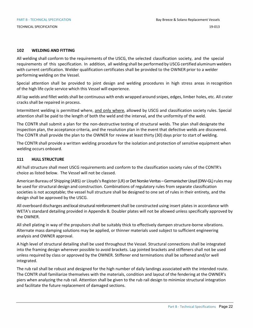
102 WELDING AND FITTING
All welding shall conform to the requirements of the USCG, the selected classification society, and the special requirements of this specification. In addition, all welding shall be performed by USCG certified aluminum welders with current certification. Welder qualification certificates shall be provided to the OWNER prior to a welder performing welding on the Vessel.
Special attention shall be provided to joint design and welding procedures in high stress areas in recognition of the high life cycle service which this Vessel will experience.
All lap welds and fillet welds shall be continuous with ends wrapped around snipes, edges, limber holes, etc. All crater cracks shall be repaired in process.
Intermittent welding is permitted where, and only where, allowed by USCG and classification society rules. Special attention shall be paid to the length of both the weld and the interval, and the uniformity of the weld.
The CONTR shall submit a plan for the non-destructive testing of structural welds. The plan shall designate the inspection plan, the acceptance criteria, and the resolution plan in the event that defective welds are discovered. The CONTR shall provide the plan to the OWNER for review at least thirty (30) days prior to start of welding.
The CONTR shall provide a written welding procedure for the isolation and protection of sensitive equipment when welding occurs onboard.
111 HULL STRUCTURE
All hull structure shall meet USCG requirements and conform to the classification society rules of the CONTR's choice as listed below. The Vessel will not be classed.
American Bureau of Shipping (ABS) or Lloyds's Register (LR) or Det Norske Veritas – Germanischer Lloyd (DNV-GL) rules may be used for structural design and construction. Combinations of regulatory rules from separate classification societies is not acceptable; the vessel hull structure shall be designed to one set of rules in their entirety, and the design shall be approved by the USCG.
All overboard discharges and local structural reinforcement shall be constructed using insert plates in accordance with WETA’s standard detailing provided in Appendix B. Doubler plates will not be allowed unless specifically approved by the OWNER.
All shell plating in way of the propulsors shall be suitably thick to effectively dampen structure-borne vibrations. Alternate mass damping solutions may be applied, or thinner materials used subject to sufficient engineering analysis and OWNER approval.
A high level of structural detailing shall be used throughout the Vessel. Structural connections shall be integrated into the framing design wherever possible to avoid brackets. Lap jointed brackets and stiffeners shall not be used unless required by class or approved by the OWNER. Stiffener end terminations shall be softened and/or well integrated.
The rub rail shall be robust and designed for the high number of daily landings associated with the intended route. The CONTR shall familiarize themselves with the materials, condition and layout of the fendering at the OWNER’s piers when analyzing the rub rail. Attention shall be given to the rub rail design to minimize structural integration and facilitate the future replacement of damaged sections.

PART B - TECHNICAL SPECIFICATION Bay Breeze & Solano Replacement Vessels
TECHNICAL SPECIFICATION 19-013
Part B - Technical Specifications Page 23
All framing shall provide for proper limbering in all sections to allow the flow of water to the appropriate bilge suction lines. All limbering holes shall be large enough to not be clogged by small bilge debris. This aspect shall be reviewed and approved during the detailed engineering and design phase.
All structure IWO of the propulsion engines shall be designed to provide the best possible access for maintenance. As an example, the frames under the engines shall be as low as possible to allow the best clearance for dropping the oil pan in place. The side framing IWO of the tight sides of the engines shall be minimized as best possible to provide the best clearance possible. As an example, suppose a standard side frame is 150mm deep with cutouts for 50mm side longs and the designer can lower that side frame to 100mm deep without cutouts and other scantling changes. These types of frame modifications should be done for better maintenance access. All such structural considerations for maintenance access shall not compromise the structural design of the vessel or the standards to which the other elements in the vessel are designed to.
126 TANKS
The CONTR shall provide tankage in accordance with Table 126-1.
Table 126-1 – Vessel Tankage
QTY Service Capacity
2 Fuel Oil Storage Total capacity per Table 081-1, 1000 USG @ 90% per side minimum
2 Urea Tanks Sufficient to fill Every 2 days, 100 USG minimum per side
1 Potable and Fresh Water Storage 500 gallons
1 Sewage Holding 500 gallons
1 Electric Hot Water Heating Tank 10 gallons total capacity
2 Engine Room Lubricating Oil Storage Tank One 30-gallon tank in each engine room
All tanks shall meet USCG and the selected classification society’s structural requirements. Potable water, fresh water, and sewage tanks and associated systems shall comply with United States Public Health Service (USPHS) requirements. All tanks under pressure shall comply with the ASME Boiler Code.
Potable water and sewage tanks shall be coated with an approved coating system applicable to the fluid being stored. This is assuming the tanks are made from aluminum. Coating system shall be designed for the 25 year life of the vessel.
Lube oil tanks in the engine rooms shall be centrally located such that it is convenient located for both engines. The lube oil tanks shall have integrated into the design a drip tray and coaming for storing the oil fill container, funnel and oil absorbent pads. See picture below of example from another vessel.

PART B - TECHNICAL SPECIFICATION Bay Breeze & Solano Replacement Vessels
TECHNICAL SPECIFICATION 19-013
Part B - Technical Specifications Page 24
All tanks shall be independent of the hull shell and shall have sufficient space between the tank and shell structure for inspection and maintenance of the shell and the tanks. All tanks shall be supported on foundations to support the tanks under all load conditions. All tanks shall have bolted access openings for cleaning, maintenance and repair.
If the CONTR is going to propose plastic tanks in any locations they CONTR must ensure the fire load in that space meets USCG requires for fire load in a void space without SFP.
Tanks shall have Fills, Vents and Sounding provisions in accordance with Section 506.
151 SUPERSTRUCTURE
The enclosed passenger deck areas shall be constructed from a USCG approved material subject to section 101 and well insulated from exterior weather, noise, and odors of the machinery plant. Final arrangement and details to be determined in the detailed design engine engineering phase.
163 SEACHEST
The CONTR shall design independent sea chests that are suitable sized for maintenance, repair and coating of the sea chest and the connecting pipes. The final arrangement of the sea chests shall be determined in the detailed engineering and design phase. The Contractor may propose to group certain items into a common sea chest as long as their design criteria are compatible. As an example, the main engines typically have pressurized sea chests were the generators do not. Items like fire pumps and bilge can accommodate either. At a minimum the main engines shall be on separate sea chests to ensure operation redundancy.
The sea chests shall be fitted with large zinc anodes for cathodic protection. The anodes shall be ZHC-42 or equivalent. The anodes shall be mounted as per the requirements of the cathodic protection section of these specifications.
The sea chests shall be designed such that there are no pockets that can accumulate marine growth and debris. They shall also be designed such that coating and repair of the coating systems can be completed easily by average level shipyard workers skill level.

PART B - TECHNICAL SPECIFICATION Bay Breeze & Solano Replacement Vessels
TECHNICAL SPECIFICATION 19-013
Part B - Technical Specifications Page 25
The sea chests shall be designed and fabricated with valved vent lines that terminate above the main deck. The vent valves shall be flanged, no direct threaded fittings in the sea chests shall be allowed.
167 HULL DOORS, HATCHES AND MANHOLES
Weathertight doors shall be aluminum quick acting. Exterior joiner doors shall be gasketed, of hollow aluminum construction, thermal insulated, meeting USCG requirements for structural fire protection where applicable. Exterior doors into the passenger cabin shall be of sturdy construction, as manufactured by PACIFIC COAST MARINE INC. brand preferably of the hinged type. Following Sea Trials and prior to Delivery, all doors shall be tested for proper closure and tightness and deficiencies shall be corrected. The OWNER shall approve the door schedule prior to ordering any doors.
Engine room doors shall be powder-coated stainless steel with stainless fasteners and locksets. Doors and hatches in passenger areas shall meet the ADA requirements of Section 092 and incorporate fairings or be installed flush to eliminate all tripping hazards. All doors shall have closers and hold open latches, using marine grade materials.
Provide secondary means of escape from all machinery and other compartments as required by USCG. The hatches shall be hinged and manufactured by FREEMAN MARINE EQUIPMENT. Minimum deck hatch shall be oval 19”x26” at a minimum but 24” square should be used were they fit. The final arrangement, ingress and egress details shall be reviewed and approved in the detailed engineering and design phase. Where possible hand holds shall be provided to ease ingress and egress from deck hatches.
Manholes into void spaces and emergency escapes shall be raised above the finished deck in accordance with WETA’s standard details shown in Appendix B to prevent water from puddling. They shall be watertight, aluminum, standard positive locking type as manufactured by FREEMAN MARINE EQUIPMENT with the A-K style coaming.
Doors and hatches that are required to be closed at sea shall be so marked.
Hatches shall meet structural fire protection regulatory requirements.
171 MASTS
A main mast shall be installed as required for proper positioning of antennas and navigation lights. Platforms for antennas and lights shall be installed as required. Ladder rungs shall be fitted as required for access to perform maintenance, repairs and inspections on the mast.

PART B - TECHNICAL SPECIFICATION Bay Breeze & Solano Replacement Vessels
TECHNICAL SPECIFICATION 19-013
Part B - Technical Specifications Page 26
200 MACHINERY - PROPULSION AND SHIP SERVICE Main propulsion power for the Vessel shall be provided by waterjet propulsion units, each driven by a diesel engine burning No. 2 ultra-low sulfur diesel oil or R-99 as approved by the OEM, through a marine reduction gear. The main propulsion diesels and waterjet propulsion units shall be of sufficient power and thrust to achieve the specified Service Speed, see Section 081 of the Technical Specifications.
The OWNER acknowledges the available options for propulsion diesel engines are limited while the marine industry completes the transition from Tier 3 to Tier 4 emissions standards. The CONTR shall provide the following Propulsion Engines:
• Tier 4 certified quad 1450 bhp MAN D2862LE489 engines * Alternate engines shall be subject to the “or equal’’ process as outlined in section 830
All propulsion machinery, equipment, components, and support systems shall be new and unused. Machinery and equipment shall be manufactured by recognized manufacturers of marine propulsion equipment and systems, having the capabilities to provide service and supply parts in the San Francisco Bay Area. MAN meets these requirements.
All machinery shall be mounted so that it is accessible for maintenance and that components are removable for replacement with a minimum amount of interference. This includes keeping the overhead in way of main engines free of pipe or cable runs and installation of lifting padeyes and rails for machinery removal. All soft patch hatches for machinery removal shall be designated and maintained as interference-free zones. The transit path for machinery to and from these hatches shall also remain interference free, to the greatest extent possible. A flush, watertight, fume tight, soft patch shall be installed over the main engines, reduction gears, and generators. The soft patches will be designed for transit of the machinery in the same orientation as the machinery operates.
The CONTR shall 3D model the entire engine and jet rooms. This shall include but is not limited to all major machinery, shafting, equipment, piping, electrical wire ways, panels and any other items that will impact the operability and maintainability of the propulsion equipment. The CONTR will develop with 3D model with the OWNER and their representatives during the detailed engineering and design phase. In general, all items will be limited in their installation alongside the engines to maximize the maintainability of the main engines and gear boxes. The 3D model shall account for removal distances for all major engine, gear and waterjet components. This shall include but is not limited to harmonic balancer, high pressure fuel pump, heat exchanger, heads, liners, pistons, turbos, intercoolers, couplings, gear inspection hatches, gear components that are serviceable in place, shafts, seals, hydraulic pumps, thrust bearings, cylinders and inspections ports with raised coamings as required by the DWL. This list is to give the CONTR an idea of the items, the final list will be reviewed and approved in the detailed engineering and design phase of the project. In general, the heavier the components the better the access needs to be.
The CONTR shall design the machinery spaces with lifting eyes located where they need to be for rigging equipment for repair and maintenance. The final placement and number of rigging points shall be determined in the detailed engineering and design phase. All lifting points will be permanently labeled with their safe working load. All rigging points shall be outside of the SFP so that it does not get disturbed in the rigging process. Where lifting points may be a hazard to operating and maintenance personnel they may be provided as bolt in to remove head knocking hazards as an example.
Both Engine Rooms shall be configured for unmanned operation with remote control of all propulsion functions located in the Pilothouse. Local operating panels shall be provided in each Engine Room.

PART B - TECHNICAL SPECIFICATION Bay Breeze & Solano Replacement Vessels
TECHNICAL SPECIFICATION 19-013
Part B - Technical Specifications Page 27
Under all service conditions, the entire propulsion system shall be free of harmful vibrations throughout the entire operating range. Harmful vibration is defined as vibration capable of damaging primary or connected ancillary equipment and as specified by the equipment manufacturers. Harmful vibrations in any part of the system shall be corrected by the CONTR. A complete and thorough torsional vibration analysis of the main propulsion drive line (to include main engines, main engine mounts, shafting, couplings, gears, waterjet unit, etc.) shall be provided by the CONTR for review by the OWNER, thirty (30) days prior to installation of main engines and shafting.
The main engine, reduction gear, waterjet, and generator set vendors shall submit a comprehensive preventive maintenance program outline which will enable the OWNER to conduct routine maintenance of the machinery and equipment provided.
205 PROPULSION SYSTEM INTEGRATION
The CONTR shall employ the services of a Designated Propulsion Systems Integrator (DPSI) to provide a complete propulsion system for the Vessel including all design, engineering, calculation, analyses, machinery, equipment, hardware, inspections, tests, a n d trials. The DPSI shall have specific experience with marine waterjet propulsion units installed in high speed ferries. A qualified and experienced DPSI is desired in order to maintain, to the maximum extent possible, a source of responsibility for design, supply, warranty, and support for the majority of propulsion system machinery and components.
The CONTR and DPSI shall take responsibility for the supply of the propulsion system machinery, including the diesel engine, reduction gear, high speed and low speed couplings and shafting, including torsional and flexible types, spool spacers, resilient mounts, and flexible connections such as exhaust bellows and seawater bellows. The CONTR and the DPSI shall also take responsibility for the integration the desired “Full Power Mode” functionality addressed in Section 438. The system shall normally run at 85% of full load (reduced RPM) unless “Full Power Mode” is engaged in which case the propulsion system shall operate at 100% load (full RPM). The DPSI shall be responsible for all main engine and gearbox alarm and monitoring as per Section 438.
It is preferred that a single supplier be used for the torsional/misalignment coupling, and all shafting.
The CONTR is responsible to ensure that the correct size, rating, model, and type of propulsion machinery is selected and installed. The CONTR and the DPSI are responsible to ensure all propulsion machinery is fully integrated into a complete propulsion system package and performs to the requirements of the RFP.
The CONTR, the DPSI, and the Original Equipment Manufacturers (OEM)s for waterjets and reduction gears shall carefully determine and verify to the OWNER that the main engine, the reduction gear, and the waterjet all rotate in the correct direction to provide main propulsion as designed.
233 DIESEL ENGINES
CONTR shall provide the OWNER with a complete scope of supply for main propulsion engines, ready for installation and operation.
The CONTR shall provide, install, test, commission, and warranty the marine propulsion engines. These engines shall be heavy duty marine diesel engines in regular production. The engines are to be certified to meet EPA Tier 4 emissions criteria a s described in Section 089.
The engines shall utilize selective catalytic reduction (SCR) for compliance with EPA Tier 4. The SCRs, complete with urea dosing systems and controls, shall be provided by the engine manufacturer. The propulsion engines shall support the control, alarm, and monitoring requirements of Section 438 of the Technical Specifications.

PART B - TECHNICAL SPECIFICATION Bay Breeze & Solano Replacement Vessels
TECHNICAL SPECIFICATION 19-013
Part B - Technical Specifications Page 28
The engine mounting system design is to include optimized engine resilient mounts to reduce structure-born noise. The resilient mounts shall be provided by the engine manufacturer, of standard production release, supported by the engine manufacturer spare parts program and covered by the engine manufacturer’s standard warranties. A solid body dynamic analysis of the engine on the proposed engine mounts and the resultant predicted displacements, shall be provided.
The engine and its exhaust components shall meet all regulatory surface temperature requirements; and shall be insulated and lagged where necessary to prevent injury to personnel.
The engines shall be heat exchanger cooled, each with a plate type heat exchanger integral to the engine. Main engine aftercoolers, if provided, shall be separate circuit fresh water cooled. Engine scope of supply will include USCG- approved, flanged, raw water flex joints. The main engine coolant header tanks shall have sight gauges and alarms installed to verify coolant level without opening the header tanks, and to warn of low coolant levels. Header tank shall be integral to or attached to the engine.
The engine manufacturer shall provide a fuel treatment and filtration system for each main engine. Main engines and generators shall have separate systems that shall provide treated fuel to each engine, in accordance with Section 261 of the Technical Specifications. The filtration system provided by the DPSI shall be reviewed and approved by the OWNER. The system shall be warranted by the DPSI as meeting or exceeding all of the factory requirements for fuel cleanliness as required by the factory warranty.
All enhancement systems shall be standard factory installed, supported, and warranted systems. All propulsion engine automation, control electronics and monitoring for such systems shall be supplied by the propulsion system manufacturer and integrated into their systems.
The CONTR shall provide a shelf with spill coaming in each Engine Room to hold a five (5) gallon bucket of makeup engine coolant.
233 REDUCTION GEARS
The CONTR shall provide and install a reversing, single speed, marine reduction gear for each propulsion engine. The reduction gear ratio shall be selected through careful and thorough examination of the thrust curves by the CONTR’s engineering team and the waterjet manufacturer.
The reduction gear boxes shall be rated at the engine’s maximum continuous rating at no more than 75% of the gearboxes rating in a medium duty application. As an example, of the engine were to put out 75bhp the gearbox would be rated for a minimum of 100bhp at rated RPM in a medium duty application. The reduction gear shall be alarmed and monitored in accordance with gear manufacturer's requirements and guidance, and as per Section 438 of the Technical Specifications. The reduction gear boxes shall use the same lubrication oil as the main engines, with written approval from the gear manufacturer.
The gearbox shall be resiliently mounted to its foundation and located and positioned such that there is good access on all sides of the unit for maintenance, inspections, and repair. Replacement of clutch packs and control valves, input/output couplings, input/output shaft seals, oil coolers, and lubrication oil pumps shall not require removal of the unit or removal of soft patches. The CONTR is to make sure all major maintenance and inspections, short of total rebuild, shall be able to be accomplished in place with sufficient access.
Reduction gear oil seawater cooling circuits shall utilize duplex stainless-steel orifice controls to provide optimum operating temperatures for the gear. Details of the temperature control system shall be subject to OWNER review and approval. The piping shall be designed for the calculated low flow rate required for gearbox cooling. The orifice

PART B - TECHNICAL SPECIFICATION Bay Breeze & Solano Replacement Vessels
TECHNICAL SPECIFICATION 19-013
Part B - Technical Specifications Page 29
plate shall be used to make minor flow corrections to obtain optimum gearbox temperature. In WETA’s other vessels this is a very low flow rate.
241 PROPULSION COUPLINGS
The CONTR shall provide all propulsion shaft line and machinery couplings as required.
The torsional couplings shall be provided by the DPSI with approval from the OWNER after review of the Torsional Vibration Analysis. The coupling manufacturer shall be a common place item in normal production, Centa, Vulcan, Geislinger or other.
The CONTR is responsible to ensure the following:
• The torsional couplings shall be operated within application limits of each coupling, under single cylinder misfire conditions.
• The torsional couplings shall be designed such that the elements may be replaced without disturbing the mounting position of the engine or reduction gear.
• The torsional couplings shall be designed for the maximum ambient Engine Room temperature. • The overall design parameters shall include optimized engine resilient mounts and torsional coupling
elements to provide for reduced structure born noise. • The resilient mounts and torsional couplings shall be a designed system specified by the DPSI, of
standard production release, supported by a spare parts system and covered by standard warranties.
Flexible couplings shall be capable of accommodating misalignment and isolating vibration in all directions (radial, axial, and angular) for the full range of shaft speed and motion. Couplings shall be dynamically balanced.
243 SHAFTING
The CONTR shall provide design, supply, installation, testing, commissioning, and warranty support for the propulsion shafting system. The shafting scope of supply is to include, but not be limited to, high speed and low speed composite shafting, machinery housings, hubs, adaptor plates, and spool spacers (as required), and all fasteners. The shafting shall be Geislinger or Centa.
SHAFTING DESIGN & ENGINEERING
The shafting system, complete with all components, shall be a designed system provided by the CONTR by way of the DPSI. It shall incorporate equipment of standard production release, supported by the shafting manufacturer spare parts system, and covered by standard warranties. The entire propulsion shafting system, all components and equipment included, shall be designed to meet ABS HSC standards, however ABS classification is not required.
The CONTR shall coordinate and order a torsional vibration analysis (TVA) to be conducted by the main engine manufacturer of the entire propulsion system, based on the proposed design. The complete shafting system including all components shall not be ordered until the TVA result is produced and accepted by all respective manufacturers. Letters from all the respective firms shall be submitted indicating their review of the TVA and acceptance of the vibratory forces predicted in their respective equipment.
The propulsion shafting system design, torsional characteristics, and calculations shall be approved, in writing, by the CONTR. Calculations shall be provided to the OWNER for review. The calculations shall reference the

PART B - TECHNICAL SPECIFICATION Bay Breeze & Solano Replacement Vessels
TECHNICAL SPECIFICATION 19-013
Part B - Technical Specifications Page 30
respective ABS class requirements and show how the calculations meet those requirements. The requirement of the OWNER is to have the CONTR responsible for the final shafting system vibratory and torsional characteristics. The design of the shafting system shall incorporate all misalignment and torsion couplings required for a system free of harmful vibration. All couplings and seals shall provide for the range of motion allowed by the resiliently mounted engines and reduction gears. The installed rotating shafting system shall be free from damaging vibrations in all modes of operation.
An engineering summary, including data from the solid body dynamic analysis (see Section 233) and other assumptions, calculations and OEM limits shall be developed. This summary shall indicate that the overhung weights and dynamic reaction forces exhibited on the engine output flange, reduction gear input shaft, reduction gear output shaft and water jet input shaft, are within the OEM published limits. This engineering summary shall be submitted to the OWNER for review.
A whirling study shall also be conducted and provided to the OWNER for review.
The design shall include two dimensional (2D) AutoCAD® drawings, installation instructions, torque values for all fasteners and alignment tolerances and limits.
The shafting system installation drawing shall be approved by USCG and the OWNER. The CONTR shall work with the DPSI to provide the best possible access to the tight side of the engines by way of shafting offsets. The tight side of the engines is defined as the outboard side of the outboard engine and the inboard side of the inboard engine. The shafting system shall utilize Z or W configurations of cardan shafts, or similar offsets of composite shafting systems to provide the best possible clearance for maintenance. The main engines and gears do not need to be installed parallel to centerline. However, the waterjets shall be unless specific written approved is granted by the OWNER and the Hamilton Jet.
All metal parts of the shafting system shall be painted to match the engine to prevent corrosion. Provide a removable drive line spool shaft in the Jet Room aft of the reduction gear for removal and servicing the shaft seal assembly.
SHAFTING ALIGNMENT
Preliminary propulsion train alignments shall occur prior to Vessel launch. Final alignment shall be conducted after vessel launch once the vessel’s structure has reached floating equilibrium. Care shall be taken to properly account for the daily heating and cooling of Vessel structure. An alignment report will be provided by the CONTR, indicating actual alignment measurements of the complete propulsion system and indicate compliance with all OEM requirements. The report shall show all alignment measurements and their limits and signed by the CONTR and the DPSI as meeting all warranty requirements. No alignment measurements shall be delivered at their maximum limits, no more than 75% of the limit may be used. The CONTR shall be responsible for the performance and documentation of all shafting alignments. The final shaft and engine alignments shall be witnessed by the OWNER. A copy of this inspection procedure shall be agreed to and signed by the OEMs for the main engine, shafting and coupling manufacturer, the reduction gear, and the waterjet.
All propulsion shafting shall be easily removable, to allow for maintenance and repair of the reduction gear boxes, seals, couplings, and waterjets.
The CONTR is responsible to design and install removable guards over exposed shafting, shaft couplings, and all rotating machinery to prevent personnel injury and facilitate maintenance and inspections.

PART B - TECHNICAL SPECIFICATION Bay Breeze & Solano Replacement Vessels
TECHNICAL SPECIFICATION 19-013
Part B - Technical Specifications Page 31
244 SEALS
BULKHEAD SEALS
The CONTR shall provide a bulkhead seal assembly in the Engine Room/Jet Room watertight bulkhead to allow the propulsion shaft to penetrate the boundary. The design and specification of this seal shall be undertaken jointly by the CONTR and the DPSI. The seal shall allow for full range of motion of the shaft. The bulkhead seal shall be designed for robustness and durability, and for ease of maintenance and repair. The bulkhead seal shall allow for simple and straightforward removal of the high-speed shaft or the reduction gear. The bulkhead seal shall maintain the watertight integrity of the bulkhead.
The design of the bulkhead seal shall allow for servicing and removal of the reduction gear input flange and input shaft seal assembly. The design shall not require that the reduction gear come out of frame to perform the maintenance actions.
247 WATERJETS
The CONTR shall provide a complete waterjet installation from HAMILTON Waterjet. The waterjets shall be sized to allow for reliable three engine operation without cavitation. The proposal package shall provide HAMILTON’s jet matching analysis showing speed and cavitation margins on three and four engine operation. The waterjets shall be alarmed and monitored in accordance with manufacturer's requirements and guidance, and per Section 438 of the Technical Specifications.
Waterjets shall come with a complete control system as per the 252 section. All systems required for support and operation of the waterjets shall be provided and installed by CONTR. Waterjets shall be continuous duty rated at the engines maximum continuous rating and engine speed.
The waterjet OEM shall take part in all required propulsion train analyses and calculations, and shall sign off on all required calculations, analyses, tests, and inspections. The waterjet OEM shall take part in the selection of the ratio for the reduction gear in order to optimize the overall propulsion efficiency of the Vessel.
INSTALLATION ARRANGEMENTS
The waterjets are to be installed in the designated Jet Rooms inside each hull pontoon, in accordance with manufacturer's installation guidelines. The waterjets are to be located such that there is good access on all sides of the unit sufficient for maintenance and repair. Replacement of seals, belts, and other normal maintenance items shall not require removal of the unit or removal of soft patches. Spare hydraulic drive belts shall be provided and pre-installed on the drive shaft for ready use on a HAMILTON installation. The CONTR shall be responsible to ensure that all waterjet maintenance, short of total rebuild, shall be able to be accomplished in place, and with sufficient access.
If applicable, the intake side of the waterjet tunnel shall include provision for an intake grille, of water jet manufacturer's design, to prevent debris from entering the pump. The grille shall be readily removable and easily installed.
251 COMBUSTION AIR SYSTEM
Engine room ventilation systems shall be provided by Delta T Systems and are capable of supplying 115% of the total engine requirements at 100% power at 85 degrees F. Each engine room shall be equipped with fans to supply ventilation and combustion air to the engine room while maintaining positive engine room pressure under all

PART B - TECHNICAL SPECIFICATION Bay Breeze & Solano Replacement Vessels
TECHNICAL SPECIFICATION 19-013
Part B - Technical Specifications Page 32
conditions. The fans shall be fitted with variable frequency drives (VFDs) for speed modulation depending on engine room temperature. The Delta T System shall be controlled in the pilothouse and the engine room by a Delta T standard touch screens. The temperature sensor shall be placed in the exhaust stream in the engine room. Delta T shall program the VFD’s so that the minimum fan speed exceeds combustion air requirements while the engines are running.
The fire damper actuation shall be as per the 555 section. The fire dampers shall be made of corrosion-resistant material, 316 stainless steel or approved equal.
The plenums shall be fitted with Wide Manufacturing, Delta T Systems, or equal, water demisters properly fitted with drains and mounted outboard. The air inlet plenums shall be fitted with internal insulation for noise control.
Fans discharging into machinery spaces shall be arranged so that they do not blow directly on or over any electrical boxes, panels, or equipment.
252 PROPULSION CONTROL SYSTEM
The Vessel’s propulsion system controls (controlling engine throttles, reduction gears, and waterjet steering and reverse bucket) shall be provided by the waterjet manufacturer. Install an AVX tiller as reviewed and approved by the OWNER. The CONTR is responsible to ensure installation of a fully integrated propulsion controls system.
The Vessel controls shall consist of identical dual control lever systems at three stations, arranged for independent control configuration (Pilothouse main centerline station, port and starboard bridge wings). Bridge wing stations shall be arranged to optimize visibility to the passenger boarding areas, and line handling locations at the Vessel stern and bow. Waterjet controls for throttle, steering, thrust, clutch, back flush, and alarm panels shall be provided at all three (3) Vessel control locations: at the centerline captain’s chair and integrated into the Pilothouse console, and at each bridge wing station. Clutch panels shall include indicator lights to confirm position of clutch. Installations shall be similar to other WETA vessels and subject to OWNER review and approval.
All main engine local control and indication panels shall be located off the engine and shall be resiliently mounted to adjacent structure. Location of local operating panels shall provide for ease of operation and monitoring by operating and maintenance personnel, and locations are subject to OWNER approval.
The speed control and direction control actuators are subject to OWNER approval in all respects.
Remote controls in the Pilothouse shall permit main engines to be started and stopped from the Pilothouse and at bridge wing stations. E-stops shall be provided at all operating stations.
All propulsion controls, normal and back-up, shall include displays. Displays shall be powered from the same source as the control and be dimmable from a single control to the greatest extent feasible. (If the capability exists in the component, it shall be used.)
The main propulsion engine controls shall incorporate control station transfer and lock-out, and engine synchronization.
Instruments in the Pilothouse shall give a complete display of engine, reduction gear, and waterjet performance, with audible and visual alarms of propulsion system faults. See Sections 247 and 438 of the Technical Specifications for descriptions and requirements for propulsion system alarm, monitoring, and control systems.

PART B - TECHNICAL SPECIFICATION Bay Breeze & Solano Replacement Vessels
TECHNICAL SPECIFICATION 19-013
Part B - Technical Specifications Page 33
256 SEAWATER COOLING
The CONTR shall design and provide complete seawater cooling systems to support installed machinery and equipment, as applicable and required. In general, there shall be independent seachests, strainers, and piping systems for each main engine and generator. Certain items may be grouped into a common seachest as per the 163 section. The final details of all piping systems shall be reviewed and approved by the OWNER in the detailed engineering and design phase.
All valves and materials in the seawater systems shall be in accordance with Appendix B. All skin valves shall be easily accessible with visual feedback of the valve orientation. All piping shall be in accordance with the general piping requirements of Section 505.
If a valve is installed with a gear operator and a reach rod the CONTR shall ensure that visual indication of the valve’s orientation is quick and easy to identify. As an example, a contrasting colored metallic flag can be affixed to the rotating face of the gear operator that show the orientation of the butterfly valve disc.
All devices requiring seawater shall be self-priming in all modes of operation. During the detailed engineering and design phase the CONTR shall prove to the OWNER that every effort has been made to ensure that all seawater systems are self-priming.
All strainers shall be simplex basket type strainers fabricated from CuNi. All strainer details shall be approved by the OWNER in the engineering phase to ensure the highest quality units are employed.
All seawater pipes shall be analyzed to ensure that the maximum flow velocity is within industry-accepted norms for the piping material. All flanged connections to aluminum structure shall be heavily reinforced to ensure the long-term viability of the through hull. This shall include heavy insert plates and at least four (4) gussets in areas that are not designed for penetrations (seachests). All aluminum pipes in through-hull connections shall be coated in accordance with Section 631.
259 ENGINE EXHAUST
Main propulsion engine exhaust piping shall exit the vessel through the transom or inboard side shell as far aft as possible. Generator set exhaust piping shall be routed inboard and discharge into the tunnel between hulls. The Main Engine exhaust shall be a dry exhaust exiting through a cooling ring at the transom. The CONTR can provide a sea water injection ring into the exhaust stream to cool the gases prior to the overboard if all details are reviewed and approved by the OWNER. Any sea water injection ring (spray head) shall be designed and supplied by Marine Exhaust Systems (MES) or Riviera Beach Florida. The material of the injection ring will be suited to the exhaust gas temperature, either 2205 duplex stainless steel or AL-6XN as approved by the OWNER and MES. All exhaust pipes will terminate well above the waterline, with significant slope provided to avoid water ingestion into the exhaust pipe under any operating conditions or maneuvers. The outlets shall be provided with cowls on the forward side if they are side exit. If required the arrangement shall include a surge pipe to ensure sea water does not get back up into the SCR’s.
The CONTR shall carefully consider the flow of exhaust gases during normal operations and at a reasonable range of speed, heading and wind direction and ensure avoidance of:
• Re-introduction of exhaust gases into any ventilation or combustion air intakes. • Exhaust gases sweeping onto decks normally occupied by passenger or crew.

PART B - TECHNICAL SPECIFICATION Bay Breeze & Solano Replacement Vessels
TECHNICAL SPECIFICATION 19-013
Part B - Technical Specifications Page 34
Arrangement and details of engine exhaust pipe design, routing, and arrangements are of keen interest to the OWNER and shall be subject to review and approval by the OWNER prior to start of construction. The CONTR shall submit calculations, based on installed piping and components, demonstrating the installed systems do not exceed OEM back pressure, displacements, loads, or moments at all expansion joints and exhaust system connections to engines, equipment, and hull penetrations. Provide multi-ply expansion joints (wrinkle bellies) ahead of all structural penetrations. Pay particular attention to avoiding stress to piping, flanges, bellows, SCR’s and structural exhaust penetrations. The DPSI and OWNER shall review and approve the exhaust system design for full compliance with all factory warranty requirements.
All outboard engine exhaust tail pipes are to be 316L stainless steel. Schedule 10 exhaust piping with plate flanges are to be installed. Provide duplex stainless steel grade 2205 or AL-6XN for the wet part of the exhaust pipe. The use of these exotic alloys shall require the CONTR to provide for review and approval a weld procedure to ensure CONTR welded exotic alloys are welded properly.
All exhaust flange/ gasket bolts shall be retightened following successful Sea Trials. All exhaust flanges and gaskets shall be MES style captive metallic gaskets.
Install captive vibration isolators to prevent metal to metal contact and provide effective vibration isolation between any part of the exhaust system and the ship structure. At no point shall the dry exhaust systems transfer heat to the aluminum structure such that the temperature exceeds 65.5°C as per USCG requirements.
For main engine exhausts ensure that piping in the way of engine or gear removal is flanged with expansion joints for ease of removal. Flanged sections of exhaust pipe shall be no longer than 6’ in length. The system design shall incorporate to the greatest extent possible the future addition of a Diesel Particulate Filter (DPF) when require by CARB. The space reserved for a future DPF shall be determined by the OWNER and the DPSI in the detailed engineering and design phase. The space allocated will be an estimate of smaller packaging based off of product development that has not been mandated. As such the design of the vessel will not be compromised but effort will be expended to plan for the future.
EXPANSION JOINTS
Exhaust expansion joints shall be provided as needed. They shall be multi-ply, stainless steel or Inconel, provided with liners, and shall be designed, constructed, and installed to EJMA standards. Provide DME, INC. expansion joints. All expansion joints are to be provided with one free-turning flange to facilitate installation. Expansion joints shall be installed with factory-provided shipping stays in place. Shipping stays are to be removed following installation ensuring proper fit. The CONTR shall ensure proper support of the exhaust system, demonstrating adequate pipe line support and flexibility. Care shall be taken to ensure proper alignment of exhaust system with equipment and machinery. Exhaust hangers shall be designed to minimize noise transmission to the structure.
EXHAUST INSULATION
Insulate all exhaust piping, flanges, expansion joints, silencers, and SCR in both the Engine Rooms and Jet Rooms, in accordance with the following:
• Engine exhausts shall be lagged with a multi-part system made up of silicon/fiberglass outer cloth (ALPHA MARITEX Style #3259-2-SS) sewn to high temperature eighteen (18) ounce inner cloth (ALPHA SIL Style 600).

PART B - TECHNICAL SPECIFICATION Bay Breeze & Solano Replacement Vessels
TECHNICAL SPECIFICATION 19-013
Part B - Technical Specifications Page 35
• Attached to that shall be a knitted stainless steel wire tubular fabric (ALPHA MARITEX #91160) which is in direct contact with the pipe wall. Or stainless steel spring clips as per WETA vessel M.V. Scorpio.
• Install a 2" temperature mat between the silicon outer cloth and the inner cloth. • Insulation muffs are to overlap adjacent sections of insulated pipe by a minimum of 3", and lace
together with stainless steel hooks and wire. Insulation is to be installed in easily removable sections. • Insulation blankets shall be pre-sewn and removable at all flanges.
SELECTIVE CATALYTIC REDUCTION (SCR)
An SCR system will be required to meet the exhaust emission requirements of EPA Tier 4. The SCR shall meet the following requirements:
• The SCR shall be provided with factory installed sound suppression and thermal insulation packages. • Installed so that access is provided for inspection and easy maintenance of components. • The catalyst units complete for each engine shall be able to be removed and replaced with a spare unit
by two (2) persons in four (4) hours dockside. • The SCR shall be fitted with a thermal blanket that will limit the surface temperature to a maximum of
65.5°C or less to ensure that heat transmission to the space that the SCR is located in does not require additional ventilation. The ventilation exhaust shall be located close to the SCR to minimize temperature in the rest of the compartment.
• SCR housings are to be resiliently mounted and isolated from supporting structure. • The SCR shall be removable through the Engine Room soft patch while the engine remains in place. If
possible, design Engine Room air exhaust plenum for removal or servicing of the SCR unit.
MUFFLER
Based on the sound attenuation characteristics of the MAN SCR the CONTR may need to install a muffler to obtain the Contract required noise limitations. The muffler shall be dry and total isolated thermally from the vessel’s structure as per the requirements of this section. The details of the systems mufflers shall be reviewed and approved by the DPSI and the OWNER in the detailed engineering and design phase.
261 FUEL OIL SYSTEM
Each engine will be provided with independent supply and return circuits. The sizing of piping and fittings will be in accordance with equipment manufacturer’s requirements. Fuel oil return lines from main engines and generator sets shall be independent of each other all the way back to the tank.
All fuel filters and associated gauges and valves shall be located above the engine room deck plates with drip pans under the fuel filter assemblies. Special care shall be exercised in meeting USCG spray protection requirements for the fuel oil system. No pressurized fuel filters shall be located where they can spray onto dry exhaust piping.

PART B - TECHNICAL SPECIFICATION Bay Breeze & Solano Replacement Vessels
TECHNICAL SPECIFICATION 19-013
Part B - Technical Specifications Page 36
The fuel system shall incorporate duplex fuel filters or a fuel filter/coalescer (treatment) system provided by the DPSI. The use of the manufacturer’s fuel treatment system is required and shall be warranted by the DPSI.
The CONTR shall provide each hull with a hand crank fuel priming pump valved into the main fuel supply header for the main engine circuit. The pump shall be a Blackmer PA201A inline sliding vane manual pump permanently mounted and plumbed as needed for proper operation.
All fuel lines shall be routed low in the Vessel to promote flooded suctions and filters to all engines with careful attention paid to venting of entrapped air.
All piping shall be in accordance with the general piping requirements of Section 505. Fuel oil tank high level alarms and level sensing shall be provided in accordance with Appendix B.
262 LUBE OIL SYSTEM
The CONTR shall provide clean/dirty lube oil systems for the shoreside refilling and removal of lube oil. Clean oil will be pumped onto the Vessel via the OWNER’s shoreside pump. Dirty lube oil shall be pumped out of the vessel via the OWNER’s dirty shore side pump.
The system shall have a single QD in each engine room’s access fiddley for connection of the appropriate shoreside oil system in accordance with Section 506. That QD shall be plumbed to a lube oil manifold mounted in the engine room. The manifold shall have a purge port for flushing dirty lube oil out of the piping prior to filling with clean lube oil.
Each main propulsion engine, gear and generator shall be outfitted with a remote lube oil connection. The remote lube oil connection shall consist of an isolation valve directly connected to the oil sump. There shall be a hose connection from the isolation valve to the hard piping to provide vibration isolation for the machinery. The system shall be hard plumbed to the greatest extent possible as per the piping requirements of section 505.
Each engine room shall be equipped with a lube oil station. The lube oil station shall consist of:
The clean lube oil tank shall meet the requirements of Section 126 and be located as high in the engine room as possible to facilitate the gravity-fed supply to the oiling cans.
298 OPERATING FLUIDS
Upon completion of all work defined in this contract, all operational fluids in all equipment will be topped up with manufacturer approved fluids. The Vessel shall be trialed and delivered with all equipment ready to operate according to manufacturers’ recommendations.
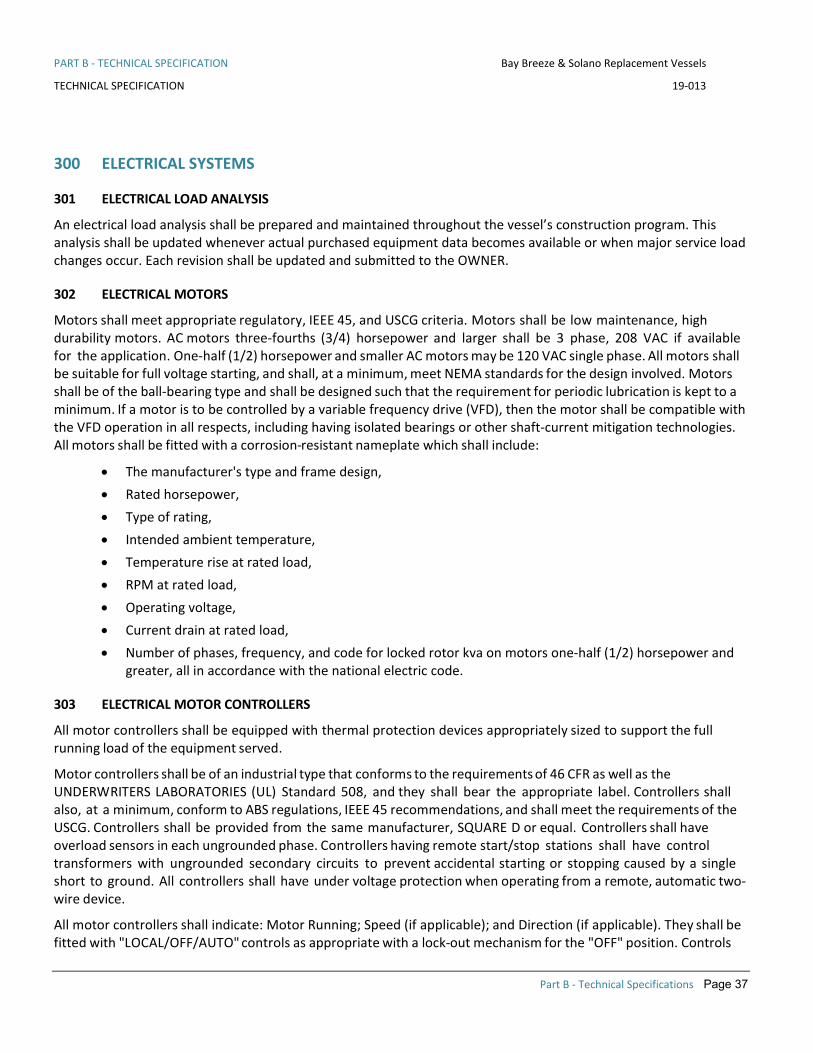
PART B - TECHNICAL SPECIFICATION Bay Breeze & Solano Replacement Vessels
TECHNICAL SPECIFICATION 19-013
Part B - Technical Specifications Page 37
300 ELECTRICAL SYSTEMS
301 ELECTRICAL LOAD ANALYSIS
An electrical load analysis shall be prepared and maintained throughout the vessel’s construction program. This analysis shall be updated whenever actual purchased equipment data becomes available or when major service load changes occur. Each revision shall be updated and submitted to the OWNER.
302 ELECTRICAL MOTORS
Motors shall meet appropriate regulatory, IEEE 45, and USCG criteria. Motors shall be low maintenance, high durability motors. AC motors three-fourths (3/4) horsepower and larger shall be 3 phase, 208 VAC if available for the application. One-half (1/2) horsepower and smaller AC motors may be 120 VAC single phase. All motors shall be suitable for full voltage starting, and shall, at a minimum, meet NEMA standards for the design involved. Motors shall be of the ball-bearing type and shall be designed such that the requirement for periodic lubrication is kept to a minimum. If a motor is to be controlled by a variable frequency drive (VFD), then the motor shall be compatible with the VFD operation in all respects, including having isolated bearings or other shaft-current mitigation technologies. All motors shall be fitted with a corrosion-resistant nameplate which shall include:
• The manufacturer's type and frame design, • Rated horsepower, • Type of rating, • Intended ambient temperature, • Temperature rise at rated load, • RPM at rated load, • Operating voltage, • Current drain at rated load, • Number of phases, frequency, and code for locked rotor kva on motors one-half (1/2) horsepower and
greater, all in accordance with the national electric code.
303 ELECTRICAL MOTOR CONTROLLERS
All motor controllers shall be equipped with thermal protection devices appropriately sized to support the full running load of the equipment served.
Motor controllers shall be of an industrial type that conforms to the requirements of 46 CFR as well as the UNDERWRITERS LABORATORIES (UL) Standard 508, and they shall bear the appropriate label. Controllers shall also, at a minimum, conform to ABS regulations, IEEE 45 recommendations, and shall meet the requirements of the USCG. Controllers shall be provided from the same manufacturer, SQUARE D or equal. Controllers shall have overload sensors in each ungrounded phase. Controllers having remote start/stop stations shall have control transformers with ungrounded secondary circuits to prevent accidental starting or stopping caused by a single short to ground. All controllers shall have under voltage protection when operating from a remote, automatic two- wire device.
All motor controllers shall indicate: Motor Running; Speed (if applicable); and Direction (if applicable). They shall be fitted with "LOCAL/OFF/AUTO" controls as appropriate with a lock-out mechanism for the "OFF" position. Controls

PART B - TECHNICAL SPECIFICATION Bay Breeze & Solano Replacement Vessels
TECHNICAL SPECIFICATION 19-013
Part B - Technical Specifications Page 38
shall be near the controlled motor, as far as practicable. They shall include a corrosion resistant nameplate with the following information:
• Manufacturer • Type and Serial Number • Voltages and Phases • Current or Horsepower • Operating Instructions
A plastic laminated wiring diagram of each controller shall be permanently mounted inside the controller cover.
305 NAMEPLATES AND LABELS – ELECTRICAL EQUIPMENT
Nameplates shall be fitted on all circuit breakers, distribution panels, shore receptacles, and connection boxes. Nameplates shall show "fed from" and location on all breaker panels. Amperages of breakers shall also be marked.
Plastic laminated circuit directory cards 8-1/2" by 11" (maximum) and one-line diagrams shall be provided inside panel boxes and switchboards to identify the equipment and service supplied from each circuit including breaker amperage.
All nameplates shall be adhered to the equipment with a permanent marine adhesive, 3M 5200 or approved equal.
311 ELECTRICAL SYSTEMS - GENERATING
The Vessel shall be equipped with two Pacific Power Group, model MG115, John Deere 4045AFM85 diesel powered generator sets, rated at 99 kWe, 123kVA , 0.8 PF, 208 V , 60Hz, 3 phase, with 110% load Capability . Generator sets has be equipped as per the Hydrus and Dorado class vessels.
They shall be EPA Marine Tier 3 certified engines with Marathon Mariner generators, Model 363PSL3127 rated at 105kW @ 95C/50C temp rise, 208VAC, including PMG and PM500 AVR with +/- 0.5 3 Phase sensing, heavy duty rectifier, reinforced windings and polybutadiene winding coating for salt air environment. A circuit breaker shall be installed in an enclosure, mounted on and wired to the generator set.
Pacific Power Group shall be contacted for a quote for configuration of the gensets matching WETA’s requirements.
Each generator shall be capable of supplying the Vessel's factored AC electrical load at eighty-five percent (85%) of its continuous rated capacity and shall be capable of starting the largest motor without requiring load shedding.
Voltage regulation shall be ± one percent (1%). The generators are not intended to be operated in parallel.
The generator sets (gensets) shall be provided and installed, complete with an active master local control panel, instrumentation, governors, regulators, alarm sensors, automatic and manual shutdowns, cooling systems with an engine mounted CuNi heat exchanger, FW cooling, wet exhaust, drip pan, 24V electric starting system, alternator and battery with appropriate bulkhead mounted charging system. The coolant header tank and remote reservoir shall have sight gauges installed to physically verify coolant level without opening the header tanks. The gensets shall be provided with an aluminum subframe and coated white in accordance with Section 633.
The gensets shall be test run at the factory under 100% load for four hours prior to Delivery. The purpose of this requirement is to "break in" the engines.

PART B - TECHNICAL SPECIFICATION Bay Breeze & Solano Replacement Vessels
TECHNICAL SPECIFICATION 19-013
Part B - Technical Specifications Page 39
A fully manual means of starting and stopping generators shall be provided locally at the genset and be independent of the Vessel’s automation system. A fully manual means of opening and closing generator and shore power breakers, including power available indicators, shall be provided locally at the switchboard and pilothouse. Start and stop functionality shall be independent of the Vessel’s automation system. The automation system shall indicate the generator and shore power status. Indication alarms shall be integrated into the vessels alarm system to provide generator and shore power failure. Load transfer shall be protected and alarmed in order to preclude load transfer with reverse current.
Shore power interlock shall include phase monitoring to ensure shore power is phased correctly prior to closing the shore power breaker.
The OEM instrument panel shall include DC voltage, water temperature, oil pressure, Start/Stop and elapsed run time meters. The panel shall be located off the generator set and shall be resiliently mounted to an adjacent structure and arranged for ease of operation and monitoring. Displays shall not require scrolling to view normal operating parameters.
The gensets shall be provided with an OEM-supplied, integrated diagnostic panel providing comprehensive indication of the cause of generator set shutdown and faults. The generator sets and diagnostic panel shall be configured for engine room and pilothouse displays as per section 438.
313 BATTERY SYSTEMS
All batteries provided onboard the Vessel shall be maintenance-free AGM marine type as approved by the OWNER during the detailed design and engineering phase.
Batteries and battery banks shall be fully accessible for maintenance and located well clear of the bilge. All batteries shall be contained in USCG approved battery boxes with covers. All batteries shall be installed with USCG approved disconnect switches. All batteries shall be provided with appropriately sized chargers consistent with the requirements of the battery manufacturer.
Each propulsion engine shall be fitted with its own starting battery and charging system. Each ship service generator shall be fitted with its own starting battery and a fully independent battery charger.
The radio emergency power supply shall be a battery and charger that are sized and located to comply with both FCC regulations and the manufacturer of the radios.
Batteries providing emergency power support of the propulsion control systems shall be sized to provide a "get home” capability.
AC-powered battery chargers shall be provided by a single manufacturer, Mastervolt MASS Series.
Three (3) 120-watt solar panels shall be fitted. Two shall be series connected to provide 24 VDC via a solar controller and connected to charge the Pilothouse’s 24 VDC batteries. The other shall be connected via a solar controller to charge the 12 VDC navigation batteries.
314 POWER CONVERSION EQUIPMENT
The CONTR shall provide voltage inverters to service any AC-powered navigation and communications equipment. All battery banks and chargers shall be fully integrated into the Vessel’s alarm system. AC systems requiring backup power shall use properly sized and integrated marine batteries and inverters. UPS-type inverters shall not be used.

PART B - TECHNICAL SPECIFICATION Bay Breeze & Solano Replacement Vessels
TECHNICAL SPECIFICATION 19-013
Part B - Technical Specifications Page 40
321 CABLES & CABLE INSTALLATION
VFD drives shall have their wiring isolated or shielded from other cables to prevent electrical noise problems. Control, sensing and data cables shall be mounted separately from line power cables.
Cables shall be low smoke zero halogen IEEE 45 approved. Cables shall be Tricad BV series or approved by the owner. Wiring and cabling shall meet the requirements of USCG and be of sufficient size to sustain enough fault current to trip the circuit breaker’s instantaneous trip devices. Power distribution cabling shall be sized for a maximum voltage drop of five percent (5%).
CONTR shall install two spare multi-conductor (14/7 conductor) cables dead headed between each engine room and the Pilothouse, and engine room to engine room, and engine room and nearest lazarette.
CONTR shall install two spare power conductor (12/3) cables dead headed between each engine room and the Pilothouse.
Wireways shall be arranged to facilitate the operation, maintenance and future retrofits to the vessel. The wire ways shall be constructed from off the shelf components manufactured from aluminum and stainless steel that are light weight. Custom cross tier or tray wireways shall be review and approved by the OWNER in the detailed design and engineering phase.
Wireways in the machinery spaces shall be located such that the wireways do not affect access to the machinery for operation and maintenance. Wireways in machinery spaces shall also be located such that they do not represent a hazard to crew members under 6’ 4” tall. wiring shall not be run on the tight side of the engines or in areas where such wiring will impact maintenance access. All wiring runs shall take into account access to the tight sides of the engines and access to drop the oil pan from the engine.
The CONTR shall create a detailed wireway drawing showing the routing and materials used for the wireways. The drawings will also show the standard attachment details and wire transit details. Wire transit details shall show transits through A class, C and C’ class bulkheads in addition to any watertight transits. The drawing shall show standard details for those different types of transits including but not limited to the construction of the transit frame, the systems used to pack the transits and the Bill Of Material (BOM) showing the materials that would be ordered for the different packing systems. The BOM for the transits does not need to show quantities but will be used to ensure the transits are being packed properly and used for all future maintenance and alteration work to ensure the repair yards repack the transits with the same materials.
The wireways in the super structure will be reviewed to ensure the least amount of ceiling tiles need to be removed to pull new wires from the PH to the engine rooms and the switchboard. The design of the vessel will not be compromised to accommodate this but reviewed to ensure no unneeded jogging of the wireways or other oddities will take place.
322 SHORE POWER CONNECTION
One (1) 208-volt, 3 phase, 100 Amp shore power supply receptacle shall provide electrical supply to the Vessel when moored shoreside. The receptacle shall be located near centerline on the bow. The connection shall be per OWNER standard per Appendix B.
A marine isolation transformer shall be provided.

PART B - TECHNICAL SPECIFICATION Bay Breeze & Solano Replacement Vessels
TECHNICAL SPECIFICATION 19-013
Part B - Technical Specifications Page 41
324 ELECTRICAL SYSTEMS - SWITCHBOARDS
For each of the two generator sets, provide dead front switchboards, or main distribution panels herein referred to as switchboards. Switchboards shall have electrically operated breakers with manual override capability. Each switchboard shall be arranged with feeds from each generator and the shore power transformer. Power for operation of the generator or shore power breakers shall come from the source side of the breaker. Power available and voltage indicators shall also be provided from the source side of the breaker.
The generator controls shall not have paralleling capability.
The capability shall be provided for operator selection of power source from the switchboard or the pilothouse.
Switchboards shall be provided with local instrumentation for monitoring voltage, current, and frequency of ship service and shore power.
The switchboards shall have sufficient reserve electrical capacity and physical space to support 10% future growth.
Ground fault detection systems shall be provided for both AC and DC ground faults with indication located in the pilothouse.
Switchboards shall be Affinity Power Systems or approved equal.
331 ELECTRICAL SYSTEMS - DISTRIBUTION
The primary generating voltage is 208 VAC, 3 phase, 4 wire. All distribution panels shall be from the same manufacturer.
Power distribution shall be a 3 phase, Y-connected, 120/208 VAC system with the neutral grounded to a single point on the common 208V bus.
Electrical loads on each AC panel board shall be balanced among the three phases within five percent (5%) of the average, except that non-simultaneous loads such as heating, and cooling need not be considered together.
AC Distribution panels shall be provided as required. Anticipated panel locations are in each engine room fiddley and in the Pilothouse. Snack Bar equipment shall be supplied from a dedicated distribution panel located in an OWNER approved location in the vicinity of the Snack Bar.
DC power systems including alarm and monitoring system, communication, and navigation systems shall be supplied from storage batteries with AC-powered charging systems as described in Section 313. Emergency lighting shall be supplied per Section 332.
DC-powered control, monitoring, and alarm systems, when fed from two sources of power, shall utilize diode, best battery selector, which will feed the higher voltage of either power source without relays.
Circuit protection for DC circuits, other than for engine starters, shall be provided by distribution panels. DC distribution panels shall be installed in the Pilothouse and as required elsewhere,
All distribution panels shall be inaccessible to passengers in crew-only spaces.
332 ELECTRICAL SYSTEMS - LIGHTING
The CONTR shall provide LED lighting throughout the vessel.
Lighting fixtures shall comply with USCG Regulations. Fixtures shall bear the UL Marine classification label suitable for the location where they are utilized. General lighting in the passenger areas shall be flush mounted, LED

PART B - TECHNICAL SPECIFICATION Bay Breeze & Solano Replacement Vessels
TECHNICAL SPECIFICATION 19-013
Part B - Technical Specifications Page 42
down lights fitted with reflectors. Where possible, lighting fixtures shall be manufactured by one manufacturer, and shall have interchangeable components to the extent possible. Equipment and fixtures exposed to weather or dampness shall be watertight, with metallic parts made of stainless steel or non-metallic.
The lighting systems shall be designed and arranged to allow only the crew to control lighting in the passenger seating areas via group lighting controls in the Pilothouse. Docking and boarding lights shall be operable from the Pilothouse center helm station with fully backlit and dimmable dual position switches.
All stairways shall be adequately lit to provide safe passenger movement and support CCTV surveillance. Stairwells shall have approximately 50% more lighting then general areas.
Availability of spare parts shall be considered when selecting lighting equipment. Equipment with interchangeable parts shall be selected when practicable.
INTERIOR LIGHTING
Interior lighting in passenger areas and engine rooms shall be arranged in groups in such a way that if one circuit is out the others will give lighting coverage. One of the groups shall be a "night light" system to provide minimal but adequate lighting at night for the security cameras when the boat is non-operational and secured. This lighting shall also provide adequate lighting for the safe movement of crew and maintenance staff. The engine room lighting shall be controlled from the fiddleys. The Pilothouse overhead lights shall have a switch mounted at the entry door.
All other cabin lights shall be controlled from a Pilothouse AC power panel.
EXTERIOR LIGHTING
The Vessel shall be outfitted with exterior lighting of adequate capacity and locations to ensure passenger safety, but no fewer than twenty-four (24). All exterior light fixtures and junction boxes shall be heavy-duty marine grade items.
Exterior floodlights shall be controlled from a switch panel located in the pilothouse overhead. Lights shall be grouped and switched in zones to be determined during the detailed design and engineering phase.
Exterior located as follows:
• One each to illuminate the four side boarding stations from above • One docking lights at each boarding station • One foredeck light to illuminate the fueling operations • One foredeck light to illuminate the shore power connection • One foredeck light to operate the anchor • One foredeck light for each line handling area.
Two remotely-controlled marine searchlights, Color Light CL25-11’s shall be provided on the top of the pilothouse mounted on pedestals Port & Stbd. Remote controls shall include adjustable focus (spot or flood), elevation (tilt) up, down, left and right. Port wing shall have controls for the port searchlight, Stbd shall have controls for the Stbd searchlight and the center helm station shall have controls for both searchlights.

PART B - TECHNICAL SPECIFICATION Bay Breeze & Solano Replacement Vessels
TECHNICAL SPECIFICATION 19-013
Part B - Technical Specifications Page 43
EMERGENCY LIGHTING
Emergency DC lighting shall be provided in all spaces, including the engine rooms, which shall have emergency lights at the bottom of the ladder and over the switchboards. Emergency lighting in the passenger cabins shall be sufficient so that loss of AC power will not create a condition that will evoke passenger concern. The lighting called out below, properly applied should provide for distributed low level of lighting that will be noticeable to the passengers but not concerning. Emergency lights shall be powered from a dedicated twenty-four (24) VDC distribution system.
At a minimum emergency lighting shall be provided in the following places;
• All doors • Pilothouse (Red) • Top and bottom of all stairwells • Egress paths • Shorepower plug • Snack bar • Heads • Switchboard • Engine room access ladders • Generator • Main engine • Emergency escape hatch • Jet room access ladder • Waterjets • 333 ELECTRICAL SYSTEMS - RECEPTACLES
The CONTR shall provide at a minimum the receptacles listed in Table 333-1. Location of all receptacles is subject to OWNER approval. Watertight receptacles with ground fault interruption shall be provided for wet areas and as required by USCG. Exterior and engine room receptacles shall be fitted with weather-tight covers. All passenger and pilothouse receptacles shall include USB charging ports.

PART B - TECHNICAL SPECIFICATION Bay Breeze & Solano Replacement Vessels
TECHNICAL SPECIFICATION 19-013
Part B - Technical Specifications Page 44
Table 333-1 Receptacles
QTY Volts - Amps Location
As required 120-20 Snack Bar, to serve commissary equipment plus additional spare outlet.
As required 208-20 Snack Bar, to serve commissary equipment
40 120-15 Passenger use, in bulkhead of integrated into table leg by UES as needed
10 120-15 General use, such that any location can be serviced by a 20-foot extension cord
6 120-20 Engine Rooms (3 x each)
4 120-20 Pilothouse
4 120-20 Crew Stations (2 x each)
As required 120-20 Exterior Decks (2 x each deck)
4 120-15 Sanitary spaces (1 x each)
2 120-15 Jet Room (2 X each)

PART B - TECHNICAL SPECIFICATION Bay Breeze & Solano Replacement Vessels
TECHNICAL SPECIFICATION 19-013
Part B - Technical Specifications Page 45
400 COMMAND AND MONITORING
401 PILOTHOUSE & CONSOLE ARRANGEMENT
The Pilothouse shall be configured with the following four control stations:
• Primary control and monitoring station located on the centerline forward. • Observer’s monitoring station located to the port of centerline forward. • Port wing control station. • Starboard wing control station.
The OWNER prefers (P/S) bridge wing control stations that are common to the bridge space, with a direct line of sight to the primary control and monitoring station. Exterior bridge wing control stations will also be considered. The bridge wing control stations shall be arranged to provide an unobstructed, direct line of sight to both forward and aft passenger boarding areas and line handling locations. To achieve this line of sight, each bridge wing shall have provisions that allow the vessel operator to extend their upper body beyond the side of the vessel. The CONTR shall however, make every effort to maximize the line of sight to both forward and aft passenger boarding areas and line handling with the window(s) of a common bridge space in the closed position.
The Pilothouse arrangement shall provide the best possible all-round visibility free from window reflections and refractions. Pilothouse windows shall meet the specifications of Section 625.
PILOTHOUSE
The Pilothouse is a secure space with no public access and shall be provided with locking doors. The Pilothouse shall at a minimum be outfitted with the following equipment and features:
• A locking file cabinet. • Power receptacles per Section 333. • HVAC per Section 514. • Sun glare covers. • Windows and shades in accordance with Section 625. • Horizontal chart surface, with full size chart under non-reflective Plexiglas. • Storage for charts, publications, flares and first aid kit. • Storage for miscellaneous equipment.
CONSOLE
The console arrangement shall be of an ergonomically correct configuration, incorporating at a minimum, the specific equipment identified in Table 401-1 at each control station. The new console shall generally be arranged, built, and configured similar to OWNER vessels. The console shall be fitted with the following features:
• The console shall have a flat deck and an angled back panel. • The deck, back panel, and all other such surfaces in the Pilothouse shall be provided with a matte black
finish to prevent glare. • A foot and knee recess at the helm station.

PART B - TECHNICAL SPECIFICATION Bay Breeze & Solano Replacement Vessels
TECHNICAL SPECIFICATION 19-013
Part B - Technical Specifications Page 46
• The console shall incorporate a 4" by 4" toe kick at the bottom of the console where it meets the deck. • Two (2) means of accessing the inside of the console. • 3-way switched lighting with minimum three (3) fixtures under the console. • Power receptacles per Section 333. • HVAC to maintain temperature under console per Section 514. • Two (2) binocular boxes convenient to each chair, location subject to OWNER approval. • Two (2) keyboard trays convenient to each chair, location subject to OWNER approval.
The CONTR shall create a full mockup of the new console for OWNER approval prior to construction. The mockup shall show the arrangement of all equipment in the Pilothouse as well as the layout and orientation of Pilothouse console and demonstrate the layout of Pilothouse windows, especially as they relate to crew sight lines.
Table 401-1 – Control Station Equipment
Feature / Equipment Spec Ref.
Port Bridge Wing Station
Observer Station
Center Helm Station
Stbd Bridge Wing Station
Full follow up tiller - console mounted, waterproof 252 x x x
Rudder angle indicators (included in waterjet controls) 252 x x x
Digital engine display for CFR119.410(b) 252 x x x
Dual function control heads (throttle and shifting) for port and starboard engines
252 x x x
Control transfer and accept button 252 x x x
Waterjet backup controls (steering and throttle) 252 x x x
Helm chairs 401 x x
Trackball & keyboard for operation of AIS/ECS (wired) 423 x
Mouse & keyboard for operation of AIS/ECS (RF wireless) 423 x
Radar displays 423 x x
Electronic chart display 423 x
VHF Radios (3) 441 x
VHF RAM microphones 441 x x

PART B - TECHNICAL SPECIFICATION Bay Breeze & Solano Replacement Vessels
TECHNICAL SPECIFICATION 19-013
Part B - Technical Specifications Page 47
Table 401-1 – Control Station Equipment
Feature / Equipment Spec Ref.
Port Bridge Wing Station
Observer Station
Center Helm Station
Stbd Bridge Wing Station
All navigation equipment displays 423 x
All communications equipment controls x
Navigation lighting controls 422 x
Port Searchlight controls 332 x x
Stbd Searchlight controls 332 x x
Video surveillance monitors 439 x
Whistle push button 444 x x x
AIS 455 x
Man overboard button – linked to GPS & Nav displays 451 x
PA system microphones 433 x x x
All instrument lighting (LCD, displays and status/alarm indicator lights, etc.) shall be equipped with physical dimmer controls for night operation and to minimize reflections. Dimmer range shall be infinitely variable from lights off through to full illumination. The console shall be equipped with glare shields for all displays to prevent direct sunlight and glare from shining on the display faces. The number of separate dimmer switches shall be kept to a minimum.
CAPTAIN'S CHAIR AND STOOLS
The CONTR shall provide and install two (2) metal, vinyl upholstered, captain's chairs in the Pilothouse. The chairs shall be of rugged construction using quality materials. The design of the chairs shall be ergonomically compatible with the duties of the operator. Chairs shall be manufactured by E. Vejvad Hansen of Denmark Skipper 502-lift Series or equal with full-follow-up jog (steering control) on the armrest. Chairs shall be approved by the OWNER.
The chairs shall be fully adjustable in the longitudinal position, seat height, backrest angle, and lumbar support. The chair locations shall be fully integrated with Pilothouse equipment including Vessel controls, radars, and VHF radiotelephones.

PART B - TECHNICAL SPECIFICATION Bay Breeze & Solano Replacement Vessels
TECHNICAL SPECIFICATION 19-013
Part B - Technical Specifications Page 48
413 WIFI
The Vessel shall be delivered complete with an enterprise level crew and passenger cellular based WiFi system. The system shall be similar to the systems currently installed in WETA’s fleet. The CONTR shall use ESS for the design and installation of the WiFi system so that it is compatible with WETA’s fleet. Antennas, WiFi access points, routers and modems shall be determined by ESS for the arrangement of the proposed vessel.
421 NAVIGATION & SIGNALING EQUIPMENT
The Vessel shall be delivered complete with all supplementary navigation and signaling equipment required by the USCG to include but not be limited to:
• One (1) bell meeting regulatory requirements shall be mounted as directed by the OWNER. • One (1) magnetic compass Ritchie HB-741-24V w/ light installed in the Pilothouse console at the steering
station, positioned low and on centerline for ease of visibility by the helmsman. The compass card shall be selected for maximum visibility. Magnetic compass lighting shall be red for night operation and fully dimmable. The compass shall be swung and a deviation card provided.
• Chart 18649. • Required publications including COLREGS, Coast Pilot and Light lists. • Day shapes. • Flares in waterproof container.
Table 421-1 provides specifications for equipment currently used in the OWNER fleet. The proposed equipment must have equal or better specifications.
Table 421-1 – Navigation & Signaling Equipment
Binoculars West Marine 2 Raiatea Waterproof 7x50 Center-Focus Binoculars, with installed holders
Clock and Barometer Chelsea Newport 4 1/2"
Magnetic Compass Ritchie Helmsman liquid beaded 3-3/4”
422 NAVIGATION LIGHTS
Navigation lights shall be provided in accordance with the USCG Navigation Rules, COMDTINST M16672.2D (COLREGS) applicable to the Vessel’s size and intended service. Provided the vessel proposed is less than 50M in length the DHR 60 series lights shall be used. The DHR lights have primary and spare LED drivers and LED’s, both shall be wired to the JBOX lighting panel.
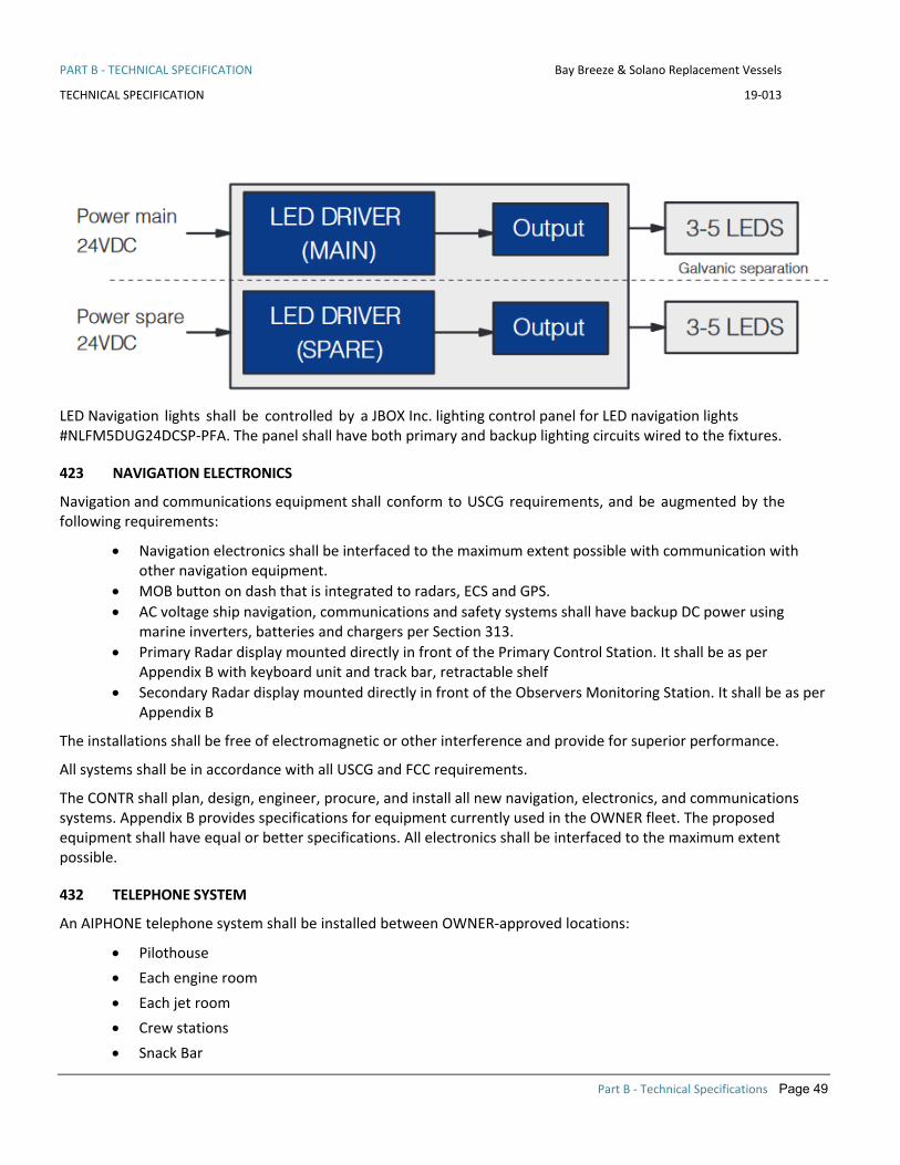
PART B - TECHNICAL SPECIFICATION Bay Breeze & Solano Replacement Vessels
TECHNICAL SPECIFICATION 19-013
Part B - Technical Specifications Page 49
LED Navigation lights shall be controlled by a JBOX Inc. lighting control panel for LED navigation lights #NLFM5DUG24DCSP-PFA. The panel shall have both primary and backup lighting circuits wired to the fixtures.
423 NAVIGATION ELECTRONICS
Navigation and communications equipment shall conform to USCG requirements, and be augmented by the following requirements:
• Navigation electronics shall be interfaced to the maximum extent possible with communication with other navigation equipment.
• MOB button on dash that is integrated to radars, ECS and GPS. • AC voltage ship navigation, communications and safety systems shall have backup DC power using
marine inverters, batteries and chargers per Section 313. • Primary Radar display mounted directly in front of the Primary Control Station. It shall be as per
Appendix B with keyboard unit and track bar, retractable shelf • Secondary Radar display mounted directly in front of the Observers Monitoring Station. It shall be as per
Appendix B
The installations shall be free of electromagnetic or other interference and provide for superior performance.
All systems shall be in accordance with all USCG and FCC requirements.
The CONTR shall plan, design, engineer, procure, and install all new navigation, electronics, and communications systems. Appendix B provides specifications for equipment currently used in the OWNER fleet. The proposed equipment shall have equal or better specifications. All electronics shall be interfaced to the maximum extent possible.
432 TELEPHONE SYSTEM
An AIPHONE telephone system shall be installed between OWNER-approved locations:
• Pilothouse • Each engine room • Each jet room • Crew stations • Snack Bar

PART B - TECHNICAL SPECIFICATION Bay Breeze & Solano Replacement Vessels
TECHNICAL SPECIFICATION 19-013
Part B - Technical Specifications Page 50
• Main Deck Switchboard
The system shall provide single pushbutton dialing. Power for this telephone system shall be provided from the emergency battery backup system. All phones shall be properly mounted and secured. Machinery Spaces will be provided with blue strobe lights to notify crew, AMSECO#SL-401B or equal.
A list of standard equipment used throughout the WETA fleet is provided in Appendix B and is typically provided, installed and serviced by Electronic System Support Inc. (ESS) Tel. (636) 677 0244 ext.110
433 PUBLIC ADDRESS & MESSAGING SYSTEM
The CONTR shall install a rack mounted PA system on the bridge in accordance to USCG regulations. Adequate space and slide rails shall be provided for access for connections and maintenance. Commercial/residential grade connectors and receptacles shall be replaced with hard-wired connections wherever possible. Where non-marine specific equipment is used, extra care shall be taken to secure electrical connectors, components and receptacles to prevent disconnection from vibration, vessel dynamic loads and maintenance access. All cables to the racks shall be arranged in an open mesh loom, properly secured to the rack and the vessels structure.
Jacks and microphones shall be provided at the Pilothouse console, wing stations and crew stations.
All speakers shall be high quality marine units. All exterior loudspeakers, junction boxes, and fittings shall be stainless steel or non-metallic, watertight, heavy-duty marine grade equipment with terminations sealed for protection against the effects of wind and water.
There shall be a sufficient number of loudspeakers located throughout the Vessel to meet the minimum requirements for sound pressure levels per USCG. Speakers shall be arranged in zones with individual zone volume control. The anticipated zones are:
• Foredeck • Main Deck cabin forward • Main Deck cabin aft • Stern Deck • Upper Deck cabin • Upper Deck aft • Pilothouse
The system shall be integrated with the video digital messaging system described in Section 448. This Standard Announcement & Messaging system shall be used for transmission of typical announcements/information throughout the Vessel. The system shall be arranged to receive user configurable, synchronized audio and visual announcements via a USB, SD or equal interface. The Standard Announcement & Messaging Panel shall have individual buttons to select one of eight (8) Standard announcements. Six (6) buttons shall have guards to prevent accidental initiation. The Standard Announcement & Messaging Panel shall be located in the Pilothouse within reach of the Helm Station, backlit and fully dimmable.
The audio PA system shall be designed to provide uninterrupted operation in the event of damage to a portion of the Vessel/system.
A list of standard equipment used throughout the WETA fleet is provided in Appendix B and is typically provided, installed and serviced by ESS.

PART B - TECHNICAL SPECIFICATION Bay Breeze & Solano Replacement Vessels
TECHNICAL SPECIFICATION 19-013
Part B - Technical Specifications Page 51
436 GENERAL & FIRE ALARM SYSTEM
The CONTR shall install a General and Fire alarm system in accordance with USCG requirements. This shall be integrated with the PA system. Rotating lights shall supplement audible alarms in engine rooms and appropriate lights shall supplement audible general alarms in passenger spaces. AUTROPRIME BS-200M from AUTRONICA shall be used.
438 ALARM SYSTEM
The CONTR shall plan, design, engineer and install the Alarm System. Vessels in the OWNER fleet use custom standalone alarm systems from the following vendor:
• Custom ICMS from Axis Engineering, tel. (619) 757 3600.
The OWNER wishes to maintain commonality in the fleet to increase serviceability. The CONTR is responsible for all liaisons with the OEM in order to provide a complete system, including all hardware. The CONTR shall verify all CONTR furnished components of the system are compatible with the ICMS.
The system shall be arranged to alarm and annunciate in the Pilothouse and locally for engine alarms, ship service generator alarms, and ship system alarms. The alarms shall be self-monitoring, and independent of the functions monitored. Alarm sensors for ship service generators shall cause annunciation of the fault prior to reaching shutdown conditions. Alarms for ship's systems shall be audible (with an acknowledge button silencer) and visual.
Alarm and Monitoring functionality for all Vessel systems shall be integrated to the extent permitted by the regulatory agencies. The intent is to limit the number of system control panels installed on the Vessel. The CONTR shall include any other alarms that may be recommended by equipment manufacturers. The CONTR shall budget for an Integrated Control, Alarm and Monitoring measuring point list that contains up to of 200 channels. All of the inputs and outputs shall be determined and documented in a detailed I/O spreadsheet that will list every item, its point of interface, type of signal and sensor location. The intent of the spreadsheet is to have all of the information organized and documented so that there is no confusion about what sensors are begin used and how the systems will be designed.
All audible Pilothouse alarms shall be distinguishable as to system by different tones or tone patterns to the extent possible. All visual Pilothouse alarms shall be distinguishable as to system by differing light colors or light patterns. All alarms shall be on separate circuits in order to avoid cascading failures.
The system shall be fitted with a 19" touch screen display. The display shall include a physical dimmer and an alarm test feature. All touch screens shall be capacitive only, not resistive, with buttons adequately sized. Draft menus and pages shall be designed and provided to the OWNER for final layouts and approval.
All equipment that can be remotely started, from the Pilothouse or elsewhere, shall be fitted with a master cut-off switch at the equipment operating station in order to prevent personnel hazard.
Instruments in the Pilothouse shall give a complete readout of engine performance with audible and visual alarms of propulsion faults. Comprehensive main engine control, monitoring, diagnostic, and alarm electronic systems shall fulfill the requirements. All main engine and gearbox alarms shall be a MAN standalone system provided with the propulsion package. The MAN monitoring system shall be provided with the maximum level or monitoring and alarms possible. Any options for fine details shall be handled in the detailed engineering and design phase. The

PART B - TECHNICAL SPECIFICATION Bay Breeze & Solano Replacement Vessels
TECHNICAL SPECIFICATION 19-013
Part B - Technical Specifications Page 52
intent is to get the best monitoring and alarm package MAN has to offer. The system shall be designed and built to classification society requirements even though the vessel is not classed.
The system shall be designed to operate at 85% (reduced RPM) of possible engine load. If it is possible between MAN and Hamilton, WETA would like to have 100% (Full RPM) load available but only if it is a “Full Power Mode” that then gets alarmed, logged with date and time so WETA can tell when “Full Power Mode” has been used and for how long. As implied the system shall log when the mode has been deselected and the alarm clears. The intention is too allow the operators access to full power but only if they can be held accountable for its use.
When an online generator fails an alarm shall signal this operation when it occurs. Essential navigation systems and equipment shall remain on during generator failures.
Table 438-1 – PILOTHOUSE CONTROL, ALARM & MONITORING
Monitor Alarm Control
SHIP SERVICE GENERATORS
Generator start/stop x
Low lubricating oil pressure x
Low lubricating oil level x
Overspeed alarm x
High coolant temperature x
Low expansion tank water level x
Voltage monitor and over/under voltage x x
Over/under frequency x
Starting battery low voltage x
Generator Failure x
Engine hour meters (if not covered in PPG package) x
SHIP SYSTEMS
Main Engine Full Power Mode x x
Breaker open/close gens and shore power x
Shorepower volts amps kw frequency, breaker condition x
Bus current monitor x x
Bilge level in all voids and machinery spaces x
Fuel tank monitor and high (85% and 90%) and low level x x

PART B - TECHNICAL SPECIFICATION Bay Breeze & Solano Replacement Vessels
TECHNICAL SPECIFICATION 19-013
Part B - Technical Specifications Page 53
Table 438-1 – PILOTHOUSE CONTROL, ALARM & MONITORING
Monitor Alarm Control
Potable water tank level monitor, 100% High & Low level x x
Sewage tank monitor and 90% High level x x
Lube oil tank monitor and 90% High level x x
DC control and alarm system low voltage x x
Fire Dampers x x
All ships batteries including inverter x x
Fire & bilge pumps x x
HVAC systems x x x
All tank level senders are to be pressure sensor type based on the fluids density. All low and high alarms are to be derived from the level monitoring sensor and adjustable in the system software by the OWNER. The location, mounting and details of the sender installation shall be reviewed and approved for each location dependent on the tank geometry and the fluid in the tank.
439 CCTV SURVEILLANCE SYSTEM
A complete closed-circuit color television (CCTV) system shall be installed with fourteen (14) video cameras topside, throughout the passenger spaces, and in the engine rooms, and with centralized monitor mounted in the Pilothouse. The system shall allow complete monitoring of the engine rooms, passenger spaces, stairwells and boarding areas from the Pilothouse and shall also enhance the master's view alongside and astern during docking and maneuvering. Final locations shall be approved by the OWNER.
The system shall be designed and installed with equipment as per Appendix B. Where options exist between Pelco and Bosch, Pelco is to be used. The system shall be complete in all respects including cameras, camera mounts and enclosures, power supplies, switches, digital video recorder unit and hard drive, dedicated computer (vibration isolated mounted) with RF wireless keyboard and mouse, 19” LCD color fully hardware dimmable marine monitor, foundations, cabling, fittings, cable penetrations, junction boxes, etc.
The CCTV system shall provide for continuous recording, with a minimum of 14-day capacity before overwrite. These cameras shall be vandal resistant, weatherproof and shall have internal heaters. Cameras in engine room shall be provided with motion sensing feature.
The dedicated computer and digital recorder unit shall incorporate an inverter with a DC power backup source.
Mounting and location of all CCTV components shall be subject to OWNER review and approval.
A list of standard equipment used throughout the WETA fleet is provided in Appendix B and is typically provided, installed and serviced by ESS.

PART B - TECHNICAL SPECIFICATION Bay Breeze & Solano Replacement Vessels
TECHNICAL SPECIFICATION 19-013
Part B - Technical Specifications Page 54
441 RADIOS
The CONTR shall install three (3) new VHF radios, microphones, mounts, cabling, cable penetrations, antenna, antenna mounts, fittings, power supplies, connections, etc. as required in order to form complete marine VHF radio systems. Radios shall be as per Appendix B.
Provide and install two (2) VHF command ram microphones, one (1) at each bridge wing station. These microphones shall be wired off one of the overhead VHF radios. Install two (2) VHF radios in the overhead and one (1) in the console as designated by the OWNER. All radios are to be interfaced with GPS. All radio systems shall be in accordance with all USCG and FCC requirements. The installations shall be free of other radio interference, including interference caused by LED navigation lights.
443 DECK LOUDHAILER
Provide a complete loudhailer with foghorn as per Appendix B, with all required speakers, microphones, amplifiers, and other components. The deck loudhailer will be installed in the Pilothouse and shall feature hail, listen, talkback and fog signal. Four (4) exterior waterproof marine intercom speakers, at bow, stern and aft boarding area locations shall be installed. The use of impedance matching speakers in series and parallel configurations shall be used to allow all 4 speakers to be active at once. During detailed engineering and design phase the configuration of the loudhailer will be reviewed to ensure it meets these operational requirements.
External speakers shall be heavy-duty marine grade, stainless steel or non-metallic components and junction boxes. Mounting and location of all loudhailer components is subject to OWNER review and approval.
444 WHISTLE
An electric whistle shall be installed and shall comply with all USCG requirements. The whistle shall have an integrated fog signal feature. 2 each KB-30 Kahlenberg 24vdc (Fwd & Aft), CM-14 control module, M-512 24vdc Signal controller and M-313 6A horn buttons. Manufacturers drawing No.3-6942A represents the desired configuration. Only the external horn switches shall be required.
448 VIDEO SYSTEM
A video system shall be supplied for the Vessel comprised of up to six (6) 42" flat screen video monitors, distributed inside the passenger cabins. The system shall be capable of displaying video from a video digital messaging system.
The video digital messaging system shall be capable of feeding custom video messages as provided by the owner as well as digital video files to help the Vessel meet 49 CFR Part 39 American with Disabilities Act requirements for passenger vessels. Provisions shall be also made to allow for displaying paid advertisements.
The video digital messaging system shall be controlled from the Pilothouse and used to provide safety messaging and arrival and departure messaging in conjunction with the Public Address system described in Section 433.
A list of standard equipment used throughout the WETA fleet is provided in Appendix B and is typically provided, installed and serviced by ESS.
451 GLOBAL POSITIONING SYSTEM (GPS) AND ELECTRONIC CHARTING SYSTEM (ECS)
The CONTR shall provide a GPS system as per Appendix B with a Man Overboard (MOB) button mounted on the dash, with the type and location to be approved by OWNER. The GPS shall be interfaced other navigation displays, at a minimum with the radars, VHF radios and Electronic Charting System.

PART B - TECHNICAL SPECIFICATION Bay Breeze & Solano Replacement Vessels
TECHNICAL SPECIFICATION 19-013
Part B - Technical Specifications Page 55
The CONTR shall provide a complete personal computer (PC)-based hardware with MS Windows and software installation as per Appendix B to support independent electronic charting. Provide signal inputs from the GPS, AIS and all navigation inputs. Provide electronic charts for complete coverage of the routes to be served. Provide electronic charts for full coverage of the delivery voyage if the Vessel is to be sailed to San Francisco for delivery. The PC shall be a marinized, fanless unit with a solid state hard drive operating on DC power. The PC and its CPU, graphics and memory shall exceed the minimum hardware requirements of the navigation software, providing capacity for future software upgrades.
Only physical, hardwired com ports should be used. Serial to USB or similar adapters should not be used. Primary user interface will be a trackball and keyboard. A Secondary user interface shall be provided comprised of a RF wireless keyboard and mouse.
Mounting and location of all electronic charting components shall be subject to OWNER review and approval.
455 AUTOMATIC IDENTIFICATION SYSTEM (AIS)
Provide complete installation for the AIS system as per Appendix B. The AIS shall be integrated into the Electronic Charting System personal computer. Mounting and location of all AIS components shall be subject to OWNER review and approval.
465 DEPTH SOUNDER
Depth Sounder shall use a transducer model designed for 40 knots and as per Appendix B. The transducer shall be faired on the outside of the hull to prevent false signals. A coffer dam shall be installed in way of the transducer hull penetration with details approved by the OWNER. The transducer shall be stainless steel.

PART B - TECHNICAL SPECIFICATION Bay Breeze & Solano Replacement Vessels
TECHNICAL SPECIFICATION 19-013
Part B - Technical Specifications Page 56
500 AUXILIARY SYSTEMS
505 GENERAL PIPING REQUIREMENTS
All piping shall conform to USCG requirements for strength, materials and testing. Piping and system components shall be in accordance with:
• the requirements of this section • the specific system details contained in this specification • The WETA standard piping materials matrix in Appendix B
Piping runs shall be straight, neat, and out of the way of walkways and passageways. Pipe hangers welded to ship structure shall be suitably located to support pipe against stress and vibration. Wherever piping must be removed for maintenance or replacement of other components, flanges or take- down joints shall be fitted. Piping to rotating machinery shall have flexible connections of components suitable for the pressure and service.
Piping shall not be run on the tight side of the engines or in areas where such piping will impact maintenance access. All piping runs shall take into account access to the tight sides of the engines and access to drop the oil pan from the engine.
All piping system fasteners shall be 316 stainless steel.
To the greatest extent possible, pumps for a given service shall be provided by the same manufacturer and shall be of the same size and material.
Shore interface fittings shall conform to OWNER standard in Appendix B. All valving, fittings, and fasteners shall be high quality marine grade materials. Pot metal or nickel-plated components shall not be used.
All pipe hangers and clamps shall be stainless steel with non-conductive bushings around the pipe, ZSI Alpha, Beta or Omega series clamps.
All valves shall be high quality, quarter-turn butterfly or ball style unless required otherwise by regulatory agencies. Valves in seawater systems shall have highly corrosion resistant discs and stems i.e. Monel, Inconel, Hastelloy or equal. All seawater valves and piping shall be isolated from the hull for galvanic protection. The CONTR shall ensure all valves handles rotate in the same direction (e.g. clockwise to close or vice versa).
All valves located below deck plates shall be equipped with reach rods to be accessible from the deck plates without removing deck plates. Removable or hinged deck access hatches shall not be used to access valves unless approved by the OWNER.
All check valves shall be entirely constructed from a highly corrosion resistant material appropriate for the service intended. As an example, materials would be 316 Stainless Steel, MIL SPEC Bronze/Monel, Inconel or Hastelloy. Check valves shall not be used in sea water systems unless specifically approved by the OWNER for the material, locations and orientation of the valve.
506 VENTS, FILLS, AND SOUNDING SYSTEMS
All spaces and tanks shall be vented as required by USCG regulations. All vent openings to weather decks shall be fitted with stainless steel insect screens. Screens shall be accessible for cleaning and replacement. Vent and fill caps shall be color coded to show service following OWNER standard piping system colors in Appendix B. All vents for

PART B - TECHNICAL SPECIFICATION Bay Breeze & Solano Replacement Vessels
TECHNICAL SPECIFICATION 19-013
Part B - Technical Specifications Page 57
systems containing oil/fuel/urea or hazardous waste shall terminate above a spill containment. The containment shall have a removable plug for drainage.
Tank vents and load/off-load connections shall be configured and located such that they are not subject to mechanical damage during docking.
Visual indication be provided for fuel tanks, oil tanks, urea tanks, hydraulic tanks as well as the electronic tank level indicators. Sight gauges shall be GEM SureSite style indicators fabricated from 316SST. The CONTR shall not use the clamp on sensors on the SureSite gauges for alarms. All alarms shall be derived from the tank level senders. Tank level indication shall be provided through the alarm system as described in Section 438.
Inspection by deck hatch is acceptable for void spaces if the lowest point is visible from the deck hatch location. Otherwise, a sounding or ullage system shall be provided to determine water levels in voids.
Shoreside Connections and fittings shall be provided in accordance with Appendix B.
FUEL OIL
The fuel oil system shall be arranged so that both fuel tanks can be filled from the bow. Fuel oil fill piping to the storage tanks shall be consolidated into a central single fueling containment complete with a cofferdam and drain. Fuel tank vent system piping shall also be located within this containment area. Flameproof vents shall be fitted on each fuel tank and mounted vertically with the opening facing down. Fuel oil fill piping and vents shall be sized for fueling at sixty gallons per minute (60 GPM) from the deck fill connections to the tanks.
A two-stage high level alarm system completely independent of the primary sounding and measuring system shall be installed to prevent overfill during refueling operations. The alarm shall provide the following indications of the tank level status during refueling:
• Two (2) lights (AMBER, RED), nominally set for eighty-five percent (85%) and ninety-five percent (95%) tank capacity and located at the foredeck fueling containment. Lights shall be waterproof and be made from SS or high-quality marine grade plastic with test function.
• Audible alarms at the foredeck fueling containment and, in the Pilothouse, with the ability to silence locally or through the ICMS.
The refueling alarm shall utilize a dedicated tank level sensor in the tanks or demonstrate equivalent redundancy and have adjustable alarm points for initial setup. The refueling alarm system shall have a master switch located at the refueling station.
The fuel tank sight gauges shall be remotely installed on the engine room bulkhead for maximum utility and visibility.
POTABLE & FRESHWATER
Water tank fill and vent shall be located on the bow, separate from the fuel fill station.
LUBE OIL
A common clean oil fill/dirty oil discharge connection will be installed adjacent to the Port and Starboard engine room entry doors in a dedicated containment. Tank vents shall terminate in this containment.

PART B - TECHNICAL SPECIFICATION Bay Breeze & Solano Replacement Vessels
TECHNICAL SPECIFICATION 19-013
Part B - Technical Specifications Page 58
SEWAGE
Sewage tank suction shall be located on the bow and provided with a dedicated containment. The discharge connection shall be valved and capped and be directly compatible with the shoreside hose fittings. Sewage tank vent shall be located in such a manner as to keep odors away from passenger and boarding areas.
507 PIPING DESIGNATION & MARKINGS
All piping systems shall be color coded and stenciled in large letters at least twice in each compartment to indicate their service as set forth in Appendix B. Arrows of contrasting color to the pipe shall be applied to the pipes to indicate the direction of fluid flow under normal conditions.
All valve wheels and handles shall have engraved stainless steel name tags attached that indicate the system, purpose of the valve, and the normal position if appropriate. For example:
POTABLE WATER FILL
NORMALLY CLOSED & LOCKED
All nameplates shall adhere to the equipment with a permanent marine adhesive, 3M 5200 or approved equal.
514 HEATING, VENTILATION, & AIR CONDITIONING (HVAC)
Complete heating and ventilation systems shall be provided for the Vessel to maintain passenger comfort while underway. Designs shall conform to applicable regulatory requirements, SNAME Technical Bulletins and ASHRAE Handbooks.
Final equipment sizing, air quantities, locations and sizes for ductwork, fans, room diffusers, fire and balance dampers, return and exhaust grilles shall be determined by the CONTR to meet the requirements of this Section.
Table 514-1 – HVAC DESIGN CRITERIA
Criteria Cooling Season Heating Season
Weather 100° FDB - 71° [email protected]% 32° FDB
Sea Water 70° F 50° F
Passenger Cabins / Pilothouse 74° FDB - 62° FWB 72° F
Heating System
The enclosed passenger cabin and Pilothouse shall have space heating installed that is capable of maintaining the Passenger Cabin Temperature per Table 514-1.
PASSENGER CABIN VENTILATION SYSTEM
The passenger cabin shall be provided with ventilation openings sufficiently sized and located to maximize passenger comfort during summer months. The vents shall be arranged to maintain the flow of fresh, cool air throughout the passenger cabin. Vents shall be arranged to draw from the coolest, odor free, clean air supply available and care shall be taken to avoid the ingestion of exhaust fumes, hot air and noise from machinery or wind.

PART B - TECHNICAL SPECIFICATION Bay Breeze & Solano Replacement Vessels
TECHNICAL SPECIFICATION 19-013
Part B - Technical Specifications Page 59
Ventilation fans shall be provided to maintain air movement throughout the cabin when stationary or at slow speeds. Ventilation fans shall have controls with automatic functionality based on user defined temperature setting. The thermostat shall be located in the Pilothouse.
PILOTHOUSE AIR Conditioning
Air conditioning shall be provided in the Pilothouse space only. Air conditioning shall be accomplished by means of self-contained, roof mounted units or equal arrangement sufficiently sized to maintain the Pilothouse Temperatures per Table 514-1.
PILOTHOUSE DEFOGGING
HVAC system design for defogging of Pilothouse windows shall be properly sized to keep all Pilothouse windows clear of fog under all conditions of weather. The fans associated with the Pilothouse defogging system shall be quiet type multi-speed fans to allow operator selection of at least three (3) levels of defogging. The CONTR shall ensure that Pilothouse HVAC and defogging systems meet the noise criteria as established in Section 089 when the fans are being operated at their highest speed setting.
FIRE DAMPERS
All fire and balance dampers shall be installed with full and easy access, allowing for complete operation, maintenance, and inspection of the dampers. Fire damper installation shall allow one (1) member of the crew open or reset all of the fire dampers with a single emergency button located in the pilot house. All fire dampers, actuators, fasteners, bushings and components shall be constructed from stainless steel or non-corrosive materials. Unless specifically approved by the OWNER the fire dampers for the HVAC systems shall be electrical actuator type.
MACHINERY SPACE VENTILATION
The Engine Room ventilation system includes the combustion air and is specified separately in Section 251.
All spaces below decks that contain machinery shall be mechanically ventilated in order to maintain space temperatures and air quality suitable for human occupancy and provide ample ventilation for installed equipment cooling. The fire dampers for the engine rooms are to be provided with a manual close switch. The switch type, location and all details of its implementation shall be specifically reviewed and approved by the OWNER.
VOID VENTILATION
Every void in the vessel shall be ventilated with power ventilation. Non-machinery voids with low heat loads shall be ventilated with Delta-T 500-804XL fans to provide for some air change in the spaces. All supply and exhaust connections shall be designed to inhibit the ingestion of saltwater to the maximum extent possible. All supply and exhaust air terminations shall be fitted with WINTEB 2000HIAS series float checks.
524 AUXILIARY SEA WATER COOLING SYSTEMS
The CONTR shall provide complete piping systems to support the seawater cooling requirements of auxiliary machinery and other installed equipment as required. Individual system sea chests or thru hulls may be consolidated in a single sea chest as approved by the OWNER. Quick-opening sea strainers shall be installed ahead of all pumps and machinery with appropriate sea valves, isolation valves, gauges, and vents. Special care and attention shall be given to the arrangement and operability of the valves and access to the strainers. Stainer’s shall be simplex cast bronze Eaton 72 series strainers.
PART B - TECHNICAL SPECIFICATION Bay Breeze & Solano Replacement Vessels
TECHNICAL SPECIFICATION 19-013
Part B - Technical Specifications Page 60
Seachest coating shall be provided IAW section 631.
526 DRAINS
Drained water shall be collected and led overboard through downspouts. Drain shall be arranged such that puddles of standing water do not collect. Horizontal piping shall utilize CPVC piping whenever possible as 6061 piping in deck drains suffers from corrosion problems in the long horizontals.
Trapped deck drains shall be provided in all restrooms, storerooms, and the Snack Bar. These drains shall be directed to the sewage tank. Whenever possible CPVC shall be utilized for piping. Use of CPVC for P-traps under deck drain are required. No deck drains with integral P-traps shall be used. All CPVC shall be ASTM D1785 type.
528 SEWAGE SYSTEM
A sewage system shall be installed, collecting sewage from all installed toilets. The system shall be designed and installed to meet all USPHS regulations. The sewage-holding tank shall be sized per Table 126-1. The sewage tank shall be fitted with a high-level alarm set to 90% and tank level indication in the Pilothouse per Section 438.
The CONTR shall take particular care to properly slope the drains to the sewage tank and to provide convenient clean out ports for snaking lines.
The toilet flushing system shall be a Headhunter system utilizing low volume toilets. The toilets shall use fresh water and the supply shall be fitted with a proper USPHS inspected and approved back flow preventer. Toilets shall be fitted with a remote pushbutton mounted in the bulkhead as directed by the OWNER.
All gray water drains shall be connected to the sewage tank and shall include accessible traps fabricated from CPVC.
The sewage discharge pump shall be installed to draw from the tank and discharge to the offload shoreside connection located on the bow as described in Section 506. The sewage discharge pump shall be sized to off-load 500 gallons in five (5) minutes. The pump shall be installed in accordance with the WETA standard detailing in Appendix B with provisions for removal from the tank.
Weatherproof, lockable sewage pump controls shall be located adjacent to the shore connection fittings with a hold to pump pushbutton to prevent running the pump dry for extended periods.
A flushing fitting shall be provided adjacent to the discharge connection for flushing the shoreside discharge hose with fresh water after sewage pumping and prior to decoupling the shoreside hose. The flushing fitting should be sized to receive a 1-1/2” fire hose connection.
Sewage pump suction and discharge piping shall be installed using long radius fittings or equivalent pipe bends.
529 BILGE AND FIRE SYSTEM
Bilge piping and pumping systems shall be provided and installed so that bilges can be pumped overboard for purposes of emergency dewatering.
A fire main system shall be installed, serviced by a fire pump with fire stations located and equipped to suit USCG regulations. Fire pumps may not double as bilge pumps. Fire and bilge pumps shall be stand alone and self-priming.
Bilge pumps shall be standalone with individual pumps located in each compartment as necessary to satisfy USCG requirements and installed in accordance with the WETA standard drawing provided in Appendix B. The overboard

PART B - TECHNICAL SPECIFICATION Bay Breeze & Solano Replacement Vessels
TECHNICAL SPECIFICATION 19-013
Part B - Technical Specifications Page 61
check valves and pipe shall be sloped towards the overboard to ensure water and salt can not accumulate in the pipe and on the face of the check valves.
The fire and bilge pumps, and related systems, shall be operable from the Pilothouse as well as locally at the entrance to the space being pumped. As an example, for the engine rooms the controls would be at the engine room fiddley.
The fire main hose stations shall have recessed fiberglass enclosures. The vessel shall be fitted with fire systems in each hull, with appropriate cross connections. The CONTR shall provide complete systems to include pumps, piping, valves, gauges, and hull fittings.
533 POTABLE AND FRESH WATER SYSTEMS
Potable and fresh water systems shall be combined systems with appropriate safeguards to ensure adequate separation of the subsystems in terms of health requirements. The design and installation of the potable water and fresh water systems shall satisfy all health regulations of the USPHS.
All potable and fresh water shall be filtered ahead of the pump with a cartridge type mechanical paper filter. The potable water subsystem shall be filtered again after the pump with a cartridge type charcoal filter. Arrange filters next to each other with bypass lines and isolation valves to facilitate filter changes.
The potable water system shall include the freshwater storage tank, a filter system, a hot water tank, and potable water distribution to restroom fixtures, drinking fountains, commissary equipment and fixtures, and cleaning stations. Hot potable water shall be provided to all sinks. All potable water fixtures shall have an isolation valve installed in the potable water supply piping to the end faucet. The isolation valve shall be located as close to the fixture as practicable and shall be readily accessible for operation.
To facilitate Vessel cleaning, provide cold-water hose bibbs in the disabled-accessible restroom and in each engine room. Additionally, hose bibbs shall be provided on exterior bow and stern deck for crew use. Bow water supply shall have sufficient pressure to spray the Pilothouse windows.
A dedicated bicycle washing station with coiled hose shall be provided adjacent to the bike rack.
All hose bibs, flushing circuits and non-potable connections to the fresh water system shall be serviced from a single backflow preventer for the entire non-potable circuit. The vent (on the bottom) from the backflow preventer shall not drip onto any sensitive equipment when it eventually leaks. Back flow preventers shall meet USCG and USPHS requirements for such devices.
Potable water systems shall be flushed and disinfected in accordance with accepted standards for such procedures. The CONTR shall be wholly responsible for obtaining certification that the potable water system is fit for human consumption.
The CONTR shall provide a fresh water subsystem to also supply fresh water to:
• The Pilothouse window washers. • The toilet flushing system.
555 FIRE SUPPRESSION SYSTEMS
Fire detection, alarm and suppression systems shall be installed to protect machinery spaces in accordance with USCG requirements.

PART B - TECHNICAL SPECIFICATION Bay Breeze & Solano Replacement Vessels
TECHNICAL SPECIFICATION 19-013
Part B - Technical Specifications Page 62
The CONTR shall use FM200 for fire suppression unless a suitable alternative is approved by the OWNER. The final details and arrangements of the system shall be determined during the detailed engineering and review process.
All fire dampers shall have DC electrical actuators that can be reset by one crew member when they reset the fire system pressure switch. Indication of the fire damper orientation (Open/Closed) shall be indicated on the Alarm system, see section 438.
581 GROUND TACKLE
The CONTR shall provide ground tackle in accordance with the following requirements. In the development of the design and location of ground tackle, the CONTR shall ensure that it cannot be fouled with terminal and dock facilities by locating the anchor in a recessed storage pocket to one side of the Vessel centerline.
A lightweight DANFORTH (Fortress manufacturer) type anchor of appropriate holding power shall be provided. The anchor shall be attached to high strength galvanized stud link chain and 300' of nylon line with an orange marker buoy attached. The chain, line, and buoy shall be fitted and stowed forward, with provisions for quick release without requiring the crewmember to lift outside the railing.
The bitter end of the anchor line shall be securely attached to hull structure. The line shall be complete with closed eye socket, and shall have all necessary detachable links, swivel and fittings required for a complete anchoring assembly.
Any sliding surface for anchor movement shall be faced with UHMW plastic.
582 MOORING
Provide a minimum of fifteen (15) bitts and cleats to accommodate existing terminal facilities during all conditions of weather and tide. The CONTR shall develop a Mooring Plan, for OWNER approval. The Mooring Plan shall detail the type, number, location, and arrangement of mooring fittings. Mooring cleats shall be provided and “through rail” welded, not surface mounted. At least 6" of clearance shall be provided around cleats of bitts for safe handling.
The bitts and cleats shall be vertically positioned at main deck level. Keyhole any bulwarks in the way of line handling fittings.
The lines utilized for Vessel docking are of fixed length; this requires that the orientation of mooring fittings to the passenger boarding doors be dimensionally exact. The CONTR shall shipcheck the existing OWNER vessels and passenger dock and provide mooring fittings that are compatible with the Mooring Interface drawing provided in Appendix B.
The vessel shall be fitted with full-length rub rails that extend least 12" out from the side plating. The top of the rub rail shall be vertically positioned at the same height as the main deck. The top surface of the rub rail shall be painted with non-skid, see Table 631-1. The vertical face of the rub rail shall be left unpainted.
In developing the Mooring Plan, the CONTR shall take into account the following:
• Standardized sizes and locations for cleats and bitts. • Cleats fore and aft of each boarding area, with a minimum of 6" of clearance from superstructure and
boarding gates for safe make up of line. • Cleats and bitts provided with line cuts in bulwarks where needed. • Adequate open deck space around deck fittings to ensure safe footing.

PART B - TECHNICAL SPECIFICATION Bay Breeze & Solano Replacement Vessels
TECHNICAL SPECIFICATION 19-013
Part B - Technical Specifications Page 63
583 LIFESAVING EQUIPMENT
Life-saving and safety equipment at a minimum shall meet USCG requirements except the following:
• Inflatable Buoyant Apparatus (IBAs) for 100 percent (100%) of the Vessel shall be provided, fully outfitted and installed in locations approved by the USCG and the OWNER; with means for one (1) person launching.
• Life Jackets shall be provided in accordance with USCG requirements. Life Jackets shall be stored in dedicated bins or cabinetry which is integrated into the vessel’s interior outfit. Life Jacket storage shall be consolidated to the extent allowable by USCG to eliminate the number of storage locations. Life jackets shall be Jim Bouy to be consistent with the WETA fleet.
• Additional stowage shall be provided for a total of one hundred (100) child size life jackets; this exceeds the ten percent (10%) USCG requirement.
• Life preservers shall be stowed on both passenger decks in ratios proportionate to the seating. The CONTR's design shall completely outfit the forward boarding areas on each side of the Vessel for overboard recovery using a JASON'S CRADLE recovery system. The boarding areas shall have sufficient space for two personnel to rig, install, operate and recover personnel from the water. The vessel shall be equipped with a fully automated, electric motor driven Jason’s Cradle storage reel. The CONTR shall construct a recessed cavity in the overhead, directly above each forward boarding area. The cavity shall provide sufficient volume to house a reel while supporting the recovery geometry shown in the WETA standard detail. The CONTR can view details of this installation by ship checking the Hydrus or Pyxis class vessels for all of the automation equipment including the electric motor, brakes, controllers etc. The final details shall be reviewed and approved in the detail design and engineering phase of the project.
• Four (4) Crew PFD Work Vests, one with 50' of 3/8" floating line attached by safety carbineer. • Two (2) boat hooks, aluminum pipe with bent sheep’s crook; provide stowage clips or brackets at each
end of the Vessel at an OWNER -approved location.
The CONTR shall prepare a list of all proposed lifesaving equipment for OWNER’s approval.
PART B - TECHNICAL SPECIFICATION Bay Breeze & Solano Replacement Vessels
TECHNICAL SPECIFICATION 19-013
Part B - Technical Specifications Page 64
600 OUTFITTING
601 GENERAL ARRANGEMENT
The OWNER desires a modern, easily maintainable interior with a light, open aesthetic and good exterior visibility through large windows. Every effort shall be made to maximize passenger privacy while adding interest to the passenger seating arrangement through various combinations of aircraft-style seats and booths with tables and bench seating.
The CONTR shall determine a Vessel arrangement that includes, but is not limited to, the following general features on each deck:
PILOTHOUSE
• A raised Pilothouse with 360-degree visibility is desired. Pilothouse requirements are further specified in Section 401.
INTERIOR DECKS
• A mixture of interior seating, per Section 645. • Snack Bar per Section 651. • Ticket Station per Section 651. • Utility Storage Space per Section 654. • Unisex and ADA passenger heads per Section 644. • Wheelchair provisions per Section 092.
EXTERIOR DECKS
• Bicycle stowage per Section 672. • A mixture of covered and uncovered exterior seating per Section 645. • All boarding facilities. • Crew locker space per Section 671.
602 HULL DESIGNATING & MARKING
The CONTR shall furnish all nameplates, notices, notice frames, markings and labels, required to complete the Vessel to the satisfaction of the USCG and all other regulatory agencies. This includes the ship name on each side of the bow, and the ship name and hailing port across the stern, deck plans, safety plan, a CONTR's nameplate, and all licenses and certificates required for posting.
The CONTR shall provide Vessel name lettering and hailing port lettering made from 1/8" thick aluminum plate. The lettering shall be permanently welded to the Vessel at locations approved by the OWNER. Size and style of the lettering shall also be subject to OWNER approval thirty (30) days prior to beginning this work. The lettering shall be preserved and painted following installation.
All nameplates, labels and identification tags shall be permanently adhered to the equipment or adjacent surface with a marine adhesive, 3M 5200 or approved equal.

PART B - TECHNICAL SPECIFICATION Bay Breeze & Solano Replacement Vessels
TECHNICAL SPECIFICATION 19-013
Part B - Technical Specifications Page 65
The CONTR shall provide interior signage in accordance with the WETA standard drawing provided in Appendix B and additional signage as required to encompass:
• No Smoking signs. • Fire door markings. • Video surveillance. • Seats reserved for disabled and elderly. • No Admittance, Crew Only. • Lighted exit signs. • Lifesaving equipment locations. • Life preserver markings. • Life buoy markings. • Boarding direction signs. • Instructions for use of lifesaving equipment. • Any and all markings and notices required by USCG. • Signs denoting mobility impaired (wheelchair) facilities.
All vents, fills, and shore side connections shall be clearly marked to show their purpose and restrictions on their use.
Pipe marking details are provided in Section 507.
Fire hydrants and firefighting equipment shall each be marked to indicate the station number and hand-held fire extinguishers shall be marked with the location of their station, all per USCG requirements.
Service and other spaces not otherwise required to have markings shall have identification plates of 1/8" thick engraved aluminum material. Markings shall be compatible with the interior design scheme.
If the Vessel is provided with certified spaces (certified for deduction from gross tonnage as determined by the Tonnage Admeasurer), those spaces shall be permanently marked by center punching as required by admeasurement regulations.
Emergency lights shall be marked with a 1" high letter "E", with white lettering on a red background.
To facilitate future blasting and painting of the hulls, provide permanent skip weld marks to indicate the boot stripe location along each hull, at full load static displacement plus 6".
603 DRAFT MARKS
The CONTR shall provide vessel draft markers made from 1/8" thick aluminum plate. The draft markers shall be permanently welded to the Vessel at locations approved by the OWNER. Size and style of the lettering and draft markers shall also be subject to OWNER approval thirty (30) days prior to beginning this work. The lettering and draft markers shall be preserved and painted following installation.
604 LOCKS, KEYS, & TAGS
Weather tight doors and all joiner doors, except where otherwise specified, shall be fitted with cylindrical type locksets, with latch bolt operated by knob from sides, cylinder outside, and no means of locking on the inside.

PART B - TECHNICAL SPECIFICATION Bay Breeze & Solano Replacement Vessels
TECHNICAL SPECIFICATION 19-013
Part B - Technical Specifications Page 66
Pilothouse doors shall have cylindrical locksets with latch bolt operated by knob on the inside, cylinder on the outside and thumb turn on the inside. Interior fire doors in main vertical zone bulkheads interior stairway enclosure doors and interior passage way doors shall have cylindrical type latch sets with knobs free on both sides. Doors held open by magnetic holdbacks shall have flush-ring type handles.
All door locks on the Vessel shall be set up for single OWNER grand master key operation. The OWNER shall provide the CONTR with a Master Key.
The overall number of keys on the vessel shall be minimized and consolidated to the maximum extent possible; all keys shall be tagged and indexed.
The CONTR shall provide locks and keys for the four (4) crew lockers.
The CONTR shall provide and install a complete indexed key locker in the Pilothouse, with 4 sets of clearly marked keys of all locks.
External hatches leading to engine rooms, void spaces and other machinery spaces shall be furnished with hasps and padlocks or equal locking provisions for securing with a padlock. Manhole keys and/or wrenches shall be provided and stowed as directed by the OWNER.
612 RAILS, STANCHIONS, & LIFELINES
Handrails, grabs, and/or bulwarks shall be fitted on all decks where necessary for the safety of passengers, and for crew access. Full length hand rails shall be fit along the exterior sides of both the main and second deck for crew access, cleaning, and line handling. Intermittently placed handholds will not be acceptable. Handrail stanchions shall be of non-corrosive material. Where breaks are required for line handling, portable handrail sections and suitable grabs shall be provided for the safety of line handlers.
Provide personnel safety equipment, harnesses, tracks, rigging, fittings, railings etc. to enable crews to externally deploy lifesaving gear, service cabin top equipment, wash and maintain all windows.
The CONTR shall ensure ready access to the bow of the Vessel for the crew by providing cutouts or gates, which permit safe transit to the bow area for line-handling or other purposes.
Exterior observation decks shall be fitted with handrails and bulwarks up to a height of 42" to protect against small parcels or children falling overboard. Handrails shall be supported such that they are free from vibrations at all engine RPM’s and that reasonable loads developed by passengers do not deflect the rail course by an unacceptable amount.
Handrails shall be installed as required around machinery and elsewhere for safety of operation. Handrails shall be removable where they may interfere with repair or maintenance of equipment.
621 NON-STRUCTURAL BULKHEADS
The CONTR shall provide and install panel joiner bulkheads with finishes in accordance with the final approved interior arrangement drawings and the manufacturer’s recommendations. All joinery systems shall conform to the fire load, structural fire protection and other interior design standards as dictated by the USCG for a Vessel of this type and passenger capacity. Where possible, all lightweight materials shall be used to lower the overall weight of the Vessel.
The CONTR shall provide and install new tile-style ceiling panels as specified in Appendix B.

PART B - TECHNICAL SPECIFICATION Bay Breeze & Solano Replacement Vessels
TECHNICAL SPECIFICATION 19-013
Part B - Technical Specifications Page 67
622 FLOOR PLATES & GRATINGS
In machinery spaces, suitable gratings and flats shall be installed to allow safe access to all machinery. Deck plates and gratings shall be of aluminum anti-slip plate, flanged, and fastened to framing with standard slot type 316 stainless steel countersunk Phillips head deck screws of proper length. Ladders to machinery spaces shall be inclined versus vertical wherever practicable.
Lifting padeyes shall be installed above all engine room ladders to allow for easy lifting of parts, motors, and other heavy equipment. Lifting padeyes shall also be welded to overhead framing to facilitate equipment change out where the weight of said equipment exceeds sixty-five (65) pounds. All padeyes shall be weight tested and marked accordingly, and rated at 1000 pounds minimum.
Shaft couplings, belt drives, and other rotating and exposed machinery shall be fitted with removable guards to prevent personnel injury.
623 LADDERS AND STAIRS
Ladders shall be provided for access into all spaces. Ladders to machinery spaces shall be inclined versus vertical wherever practicable.
Vertical ladders in general, as well as inclined ladders to machinery spaces, shall be of aluminum construction where allowed, fitted with hand rails and overhead grabs as required for safe use. All surfaces of ladders shall be free of sharp corners.
Interior stairs between passenger spaces, arranged and dimensioned to support the passenger offloading requirements of Section 063, shall be designed for loads of at least 200 pounds per square foot. Stairs shall be fitted with handrails and non-slip deck treads. Treads shall be Wooster STAIRMASTER as per Table 634-1. Wherever installed, non-slip treads shall not present a tripping hazard. Handrails supported by bulkheads shall have a clear hand space per ADA guidelines.
624 NON-STRUCTURAL CLOSURES
Hardware including doors, door hardware, trim, fasteners and attachments shall be corrosion resistant satin finished stainless steel unless otherwise approved. All hardware shall be of the best marine quality, TrioVing or equal.
Doors shall be Pacific Coast Marine. Provide a security peephole in the Pilothouse door(s).
Provide rubber button stops and catch hooks for all doors. Doubler plates shall secure stops and hooks to the respective bulkhead or structure.
All exterior weather tight doors shall be fitted with closers and single lever dogs.
In general, interior doors shall be fitted with closers and not swing into an aisle or passageway. Door thresholds and sills shall meet the ADA requirements of Section 092 and incorporate fairings to eliminate all tripping hazards. All Interior doors shall be fitted with closers requiring less than five (5) pounds of pressure for operation.
All doors, interior and exterior shall be fitted with hold opens (except fire doors). All hold opens shall be located at the same height where they are accessible to all crew members without bending over. All hold opens shall be of the same type as reviewed and approved by the OWNER.

PART B - TECHNICAL SPECIFICATION Bay Breeze & Solano Replacement Vessels
TECHNICAL SPECIFICATION 19-013
Part B - Technical Specifications Page 68
625 AIRPORTS, FIXED PORT LIGHTS, & WINDOWS
Windows in the passenger spaces shall be of the bonded, frameless type and installed using an approved marine grade adhesive system such as Sika, 3M or equal. The glass shall be high quality laminated safety glass or monolithic tempered/or toughened safety glass. Glass panes shall be of a thickness required by the USCG and classification society rules but in no case less than 3/8" thick on the forward house windows and 3/16" thick elsewhere. All passenger space windows shall be fixed.
The CONTR shall integrate the sizing, layout, and design of Pilothouse windows with the Pilothouse and console arrangement described in Section 401. Visibility for the crew during Vessel operations shall be enhanced to the greatest extent possible by minimizing the size of the mullions and quantity of forward-facing Pilothouse windows. The center Pilothouse window shall be as large as possible. Windows in the Pilothouse shall be fixed except that one window on each wing station shall be a horizontal sliding window.
Forward Pilothouse windows shall be fitted with adjustable, robust, marine grade Mylar shades in guided tracks.
Provide windows or CCTV on the aft Pilothouse bulkhead for visibility aft either to the stern, or into the upper passenger cabin spaces, as applicable. The aft Pilothouse windows shall be provided with window treatments (blinds) wherever passengers could potentially see into the Pilothouse. Window treatments shall be fully integrated with the Vessel's interior decor.
Windows shall be tinted to the satisfaction of the OWNER. Pilothouse windows shall not be tinted. Windows shall be shaped to suit the superstructure. Space between clear openings shall not exceed 4-1/2".
Pilothouse windows shall be installed at an angle to minimize glare and reflections.
Window designs and installations shall allow for a two (2) hour window replacement time.
The CONTR shall minimize the number of different, individual window sizes installed on the Vessel.
626 WINDOW WIPERS
The Pilothouse window wipers shall be installed for all forward facing windows. The wipers shall cover the entire rain swept area of visibility clearing at least eighty percent (80%) of the window area. The wipers shall be Wynn Type D, Mk-V or approved equal, linear style, with variable solid-state speed control. The wipers shall have an auto-parking feature that does not obscure the window in the parked position. Quiet wiper operation is essential, the CONTR shall be responsible for ensuring that noise from operating wipers is minimized. See Section 088 for noise limits.
A fresh water window washer system shall be provided with water supplied from the Vessel's fresh water system. There shall be a single solenoid for all windows. The location of any isolation valves and/or solenoid valves shall not be where they can drip on sensitive pilot house electronics. When the valves/solenoid leak they shall leak onto a non-vital area with no electrical components and still be visible to the crew.
631 PAINT & COATINGS
The CONTR shall propose a recognized marine paint manufacturer to the OWNER for approval. The paint formulation, specification, surface preparation, environmental constraints and application, shall be in accordance with that manufacturer's recommendation and warranties. The CONTR shall provide a complete painting schedule to the OWNER for approval. Upon receipt of the OWNER's approval, painting system applications may begin. All coating systems shall be legal in the State of California.

PART B - TECHNICAL SPECIFICATION Bay Breeze & Solano Replacement Vessels
TECHNICAL SPECIFICATION 19-013
Part B - Technical Specifications Page 69
The CONTR's Painting Schedule shall be reviewed and approved by the paint vendor(s) before it is submitted to the OWNER for approval. The Paint Schedule shall include information pertaining to paint formulation, surface preparation and cleaning, environmental constraints, and application techniques and tolerances.
Paint performance, including but not limited to anti-fouling performance, shall be fully warranted by the CONTR.
INTERIOR COATINGS
The Pilothouse interior shall be flat black. The console shall be meticulously covered to prevent damage prior to delivery.
The Interior joinery of the vessel shall be constructed of honeycomb aluminum panels with HPL laminate, decorative metal finishes or microperforated aluminum sheet as required by the location of installation. The honeycomb joinery system shall be Ayres Ayrlite panels Made in the USA. The system shall be constructed using the approved Ayers aluminum extrusions, panels, assembly accessories and techniques best suited for each application. Where multiple options exist on how to connect, support, retain or finish panels the most robust method and materials shall be chosen to complete the detail. Standard details for construction shall be developed by the CONTR for review and approved by the OWNER prior to construction. All panel finishes (both sides) shall be approved by the OWNER prior to ordering any interior materials. All finishes shall be reviewed and approved for compliance with the standard WETA interior finishes and the area of application. All laminates shall be high quality and readily available. All adhesives used in honeycomb panel fabrication shall be approved by Ayres and the OWNER. The interior design shall strike a balance between light weight and a durable system suitable for years of heavy passenger service. The OWNER shall approve all panel scantlings to ensure that a suitable balance has been met. The OWNER reserves the right to consult with the manufacturer, require calculations and/or a full-size mockup if required to prove the suitability of scantlings, assembly techniques and accessories used.
EXTERIOR COATINGS
A representative exterior painting color scheme with logos and branding is provided for reference in Appendix B. The CONTR shall provide a final color scheme tailored to their Vessel configuration to the OWNER for approval within ninety (90) days of agreement award.
Exterior areas of the superstructure not exposed to view shall be left unpainted such as any removable tunnel top cladding between hulls, the inside of bulwarks, undersides of roof structures, and handrails. The CONTR shall determine all such areas with OWNER’s approval prior to painting. The inboard tunnel walls of the hull shall be painted due to recent corrosion problems with 5083 alloys in this environment.
Colors on multiple coats of epoxy primer shall be of a differing shade.
The CONTR shall exercise care in the painting of the bow and bulwarks to avoid glare and reflection into the Pilothouse. Gloss finishes on these surfaces shall be avoided.
The CONTR shall coat the inner surface of all hull penetrations with a proven marine epoxy coating system such as Blueseal or equal. Hull penetrations to be coated include, but may not be limited to, thru-hull piping connections, stern tubes and seachests. The epoxy coating system shall be applied to the entire interior surface of each hull penetration as shown in Appendix B. The Blue Seal or Amercoat 140 shall be applied over everything while the Intersleek shall only be applied to the interior of the pipe and not over the face of the flange.
Paint thickness and type shall be in general accordance with Table 631-1. In all cases, the application method, thicknesses, and recoating schedule must follow the coating manufacturer’s requirements.

PART B - TECHNICAL SPECIFICATION Bay Breeze & Solano Replacement Vessels
TECHNICAL SPECIFICATION 19-013
Part B - Technical Specifications Page 70
Table 631-1 – Vessel Coatings
Location Coating System DFT (mils) Color
Hull - waterline to keel, 6" boot stripe
Sandblast to achieve manufacturers required profile - -
Epoxy primer 5-6 mils Black
Epoxy primer 5-6 mils Light Gray
Antifouling (Intersleek) 5 mils Red
Antifouling (Intersleek) 5 mils Black
Hull - waterline to sheer and guard rails, House, and Bulwarks
Sandblast to achieve manufacturers required profile - -
Epoxy primer 4-5 mils Buff
Polysiloxane Topcoat 3-4 mils White
Weather Decks, Hull tops where accessible.
Where hull tops cannot be accessed provide the primer coat only
Sandblast to achieve manufacturers required profile - -
Epoxy primer 3-4 mils Buff
Pacific Polymers Elastodeck 5001 6-8 mils Medium Gray
Broadcast non-skid additive - -
Polysiloxane Topcoat 3-4 mils Medium Gray
Exterior house overheads, inner bulwarks, non-exposed areas
Refer to Section 631 - -
Machinery, main engines, gears and gensets OEM epoxy coatings, white - -
Hull Penetrations Mechanically achieve manufacturers required profile 2-3 mils -
Blue Seal - Filler coats (as required) 10 mils Blue or Grey
Blue Seal - Top coat 10 mils Blue or Grey
Antifouling (Intersleek) 5 mils Red
Antifouling (Intersleek) 5 mils Black

PART B - TECHNICAL SPECIFICATION Bay Breeze & Solano Replacement Vessels
TECHNICAL SPECIFICATION 19-013
Part B - Technical Specifications Page 71
631.1 PAINT & COATINGS OPTION
The CONTR shall propose an alternate coating schedule for the hull and super structure based on a premium Polyurethane based coating system. The coating schedule shall be as per the manufacturer based on the aluminum substrate and a commercial application. The CONTR shall provide with their bid an alternate coating schedule for all above waterline surfaces aside from decks that will remain as directed in the 631 section. The alternate coating schedule shall not include any fairing compound or other yacht level application details other than the high gloss extremely durable premium polyurethane-based coating system that the OWNER is looking for. All final details of the coating system shall be reviewed and approved by the manufacture and the OWNER prior to the applications of any coatings should this option be exercised.
The price for this option will be input into the option items table of the schedule of values form in Part D. The price input will be the additional amount above the regular 631 line item in the schedule values to coat the vessel with the premium polyurethane-based coating system as detailed above. As an example, if the cost of the regular 631 line item was $100 and total cost of the coating systems with the 631.1 optional polyurethane system was $150 then the line item in the optional items table of the schedule of values form in Part D would be $50.
633 CATHODIC PROTECTION
The vessel shall be fitted with passive zinc Mil spec anode-type protection system. Bolt-on passive anodes shall be provided on the hull bottoms, and at each main engine seachest in sufficient numbers, locations and weight to protect the hull for 2 ½ years. The CONTR shall provide the services of an ABYC certified specialist qualified to design the system and then to measure and provide a report of adequacy when the Vessel is afloat.
All hull anodes shall be mounted with Fraser Bronze cast round aluminum/sst hull mounts as per Fraser drawing No. FR 072.0.
Cathodic protection meters shall be installed on the Bridge to allow for assessment of each of the hulls' potential by the operators. The meters shall be Electro-Guard Model 125A meters, one for each hull with a reference cell located aft near the cathodic load in a location that will always be well submerged. The reference cells shall be mounted inside of cofferdams fabricated from pipe and standard flanges. The cofferdam shall preclude the possibility of reference failure from flooding the compartment it is located in. The closure flange of the cofferdam shall be tapped and a ¼” NPT 316sst ball valve installed where it is protected so that the cofferdam can be checked for flooding prior to opening. The protection shall make it such that crew cannot accidentally step on the valve and break it off.
Unless otherwise noted, all hardware and fasteners used in the construction of the Vessel shall be 316 stainless steel.
ISOLATION OF DISSIMILAR METALS
The assembly of dissimilar metals throughout the Vessel shall be in accordance with good shipbuilding practices and all regulatory requirements. Corrosion and Coatings Prevention in the ABS Rules for Building and Classing Aluminum Vessels shall be followed without exception.
Copper tubing is not permitted in sea water systems, and copper nickel piping shall be isolated from hull fittings. Water systems shall be constructed using the same material for piping and fittings throughout the system. Steel and other non-aluminum metal fittings shall be isolated from the aluminum structure at their mounting surfaces by means of 10 mil PVC tape or other approved methods. Isolate stainless steel from aluminum using isolation kits and products such as TEF-GEL in areas where direct contact cannot be avoided.

PART B - TECHNICAL SPECIFICATION Bay Breeze & Solano Replacement Vessels
TECHNICAL SPECIFICATION 19-013
Part B - Technical Specifications Page 72
Pumps in sea water systems shall be corrosion resistant and approved by OWNER.
634 DECK COVERING
Deck coverings shall not be applied until production work, especially welding, has been substantially completed. The decks shall be smooth and fair when deck coverings are applied. All decks shall be bare and unpainted except as noted in Table 634-1.
Table 634-1 – Deck Covering Location Type
Weather Decks See Table 633-1 for non-skid.
Pilothouse Carpet per Appendix B.
Passenger Spaces Carpeted throughout in accordance with Appendix B with a carpet cove base that meets ADA requirements of Section 10.1.
Install slip resistant FORBO vinyl flooring or equal mats just inside all passenger boarding areas per OWNER layout and direction.
Stairways Full tread WOOSTER PRODUCTS STAIRMASTER treads, safety yellow at top and bottom stair.
Restrooms & Commissary Spaces, Bow Door
Epoxy poured flooring system in accordance with Appendix B, minimum 3” coving onto all bulkheads.
Full width and depth safety treads shall be fitted on all stairs, safety yellow at top and bottom stair. Stair treads shall not present tripping hazards wherever installed.
Rubber matting shall be provided for the Pilothouse and installed in way of ship service switchboards and other electrical equipment. Matting installed in way of electrical equipment shall conform to MIL SPEC #M-15562F Type III for dielectric properties.
The selection of deck covering materials and colors shall take into account the durability, cleanability, and maintainability of such materials. The materials and colors proposed by the CONTR shall account for the fact that many areas of the Vessel will be subject to heavy foot traffic. Materials shall be selected based on their ability to hide such heavy use, yet the materials must present a pleasing appearance and contribute to the overall decor. Another factor that shall be considered in the selection and installation methods of these materials is the ease of future replacement as the deck coverings wear out over time.
After installation of finished decks, they shall be immediately and completely covered with plywood runners and cardboard protection through completion of the del ivery voyage in order to protect the finishes.
635 INSULATION
Insulation shall be provided in all exterior bulkheads, joiner doors, and overheads with a suitable vapor barrier on the occupied side of the insulation. Care shall be taken to ensure the integrity of this barrier.

PART B - TECHNICAL SPECIFICATION Bay Breeze & Solano Replacement Vessels
TECHNICAL SPECIFICATION 19-013
Part B - Technical Specifications Page 73
Acoustic insulation shall be installed in the engine rooms and shall be effective so as to limit sound to levels indicated in Section 088. The manufacturer's recommended methods shall be used for installation of the insulation. Sound leaks at doors and other openings shall be sealed to provide an acoustic sound barrier.
Machinery space insulation shall be lined with sheet metal (no perforations). The finished surface shall be designed and installed for protection of the underlying insulation and ease of cleaning.
All insulation IWO of the tight sides of the engines shall be as thin as possible. The CONTR shall choose the Structural Fire Protection (SFP) that offers best access for maintenance. Where maintenance access is impacted thicker SFP may be used and in areas of critical importance, such as the frame flanges on the tight sides of the engines the thinnest SFP should be used. As an example, Promaguard from Promat has been touted as meeting A60 for aluminum structures in 2each 10mm layers for a total thickness of 20mm. Materials such as these, provided they are USCG approved for SFP and meeting the requirements of the fire boundaries shall be used where maintenance access is critical.
Mild steel or galvanized pins shall not be used for installation of insulation. Use stick on or welded bi-metallic stainless-steel pins and stainless-steel clips. All points of insulation pins shall be cut down to dull ends to ensure the crew and maintenance staff are not punctured by pins. Sharp points left on insulation pins will pierce the protective caps and injure crew and maintenance staff. Particular attention of insultation pin details shall be pained IWO of the tight side of the engines as staff routinely will be pressed up against these areas.
Structural fire protection must be fitted throughout the Vessel in accordance with USCG requirements as specified in 46 CFR.
Engine exhausts shall be lagged per Section 259.
644 SANITARY SPACES & FIXTURES
There shall be a minimum of two (2) unisex restrooms installed on the vessel. Both restrooms shall be outfitted to meet all requirements for the accommodation of the mobility impaired (ADA). All restrooms shall be accessible only from the Vessel interior. Restrooms shall be outfitted as follows with the WETA standard items designated in Appendix B:
• Fresh water flush head, with remote mounted flushing. • One single stainless steel sink and faucet. • Mirror. • Liquid soap dispenser. • Paper towel dispenser. • Hand dryer. • Floor drain. • Overhead light. • Power ventilation. • Waste receptacle with lid. • Coat hook. • Baby change station (in ADA head).

PART B - TECHNICAL SPECIFICATION Bay Breeze & Solano Replacement Vessels
TECHNICAL SPECIFICATION 19-013
Part B - Technical Specifications Page 74
645 INTERIOR OUTFITTING
COLOR BOARDS
The CONTR shall provide the services of an experienced marine interior designer to coordinate the interior color scheme and finishes. The interior designer shall utilize WETA standard interior outfitting details, Appendix B, in order to prepare for the OWNER's approval, three (3) unique color board themes tailored to the final configuration of the vessel. These themes shall show the arrangement of furniture and colors with actual samples of the materials to be used for the seating, tables, commissary space, deck covering, bulkheads, paint, glass, doors, and window treatments.
FURNITURE AND FURNISHINGS
The details in Appendix B are provided to simplify the process of material selection for interior outfitting components and colors. If the CONTR has to choose a material that is not in Appendix B it shall be reviewed and approved by the OWNER assuming the deviation from Appendix B is justified. The selection of furniture, furnishings, and upholstery materials and colors shall take into account the durability, cleanability, and maintainability of such materials. The materials and colors proposed by the CONTR/CONTR shall account for the fact that many areas of the Vessel will be subject to heavy use. Materials shall be selected based on their ability to hide such heavy use, yet the materials must present a pleasing appearance, maximize passenger comfort, and contribute to the overall decor. Another factor that shall be considered in the selection and installation methods of furniture, furnishings, and upholstery materials is the ease of future replacement as these items wear out over time.
A mixture of seating styles and arrangements similar to existing WETA vessels is preferred.
SEATS
Provide at least the threshold number of interior and exterior seating as shown in Table 081-1. Interior cabin seating not located with fixed tables shall have drink holders, except for those seats adjacent to aisleways.
Interior seats shall be of a high quality high back design. Interior seat cushions shall be easily replaceable and constructed of materials that are suitable for a minimum of ten (10) years of service without fading or wearing. All seating shall comply with the WETA standards for interior outfitting details in Appendix B.
Removable interior seat covers are not desired, and the seat should not require covers in order to meet the ten (10) year service life.
Exterior seats shall be of aluminum construction with a corrosion resistant anodized or powder coated finish.
Seats shall be installed using welded seat tracks.
Seat spacing shall be per Appendix B and shall satisfy regulatory requirements.
TABLES
Tables shall be track mounted with aluminum frames similar to those of the seats. Tops shall be aluminum honeycomb panel construction with plastic laminate finish and sea rails with cutouts for cleaning. Dimensions, numbers, and locations similar to OWNER’s existing vessels.

PART B - TECHNICAL SPECIFICATION Bay Breeze & Solano Replacement Vessels
TECHNICAL SPECIFICATION 19-013
Part B - Technical Specifications Page 75
METAL CASE FURNITURE
Case goods (desks, cabinets, etc.) shall be of aluminum. The gauges of aluminum shall be heavy enough to provide the necessary degree of strength and stability for marine use.
Drawers and drawer guides shall be constructed so as to operate freely and without noise. All drawers and doors shall have catches with rated strength such that they will remain closed when tilted thirty degrees from horizontal, but drawers shall be removable at will. Drawers shall have side glides and positive stops to prevent accidental opening.
Doors and drawer heads in metal furniture shall be of vermin proof sealed box construction, braced with proper reinforcements to prevent undue racking or twisting. Doors shall be equipped with rubber bumpers to prevent rattling.
GENERAL WALL DECOR
Bulkheads in all enclosed passenger areas shall be finished in compliance with WETA standard details of Appendix B. Flooring shall be extended upwards a minimum of 4" from decking on all bulkheads.
HARDWARE
Coat hooks (MCMASTER-CARR #12845A21, stainless steel) shall be fitted with tamper proof screws, and located at least 72" above the deck, as follows:
• Four (4) in the Pilothouse. • Forty (40) on the enclosed passenger deck(s). • Two (2) installed in each passenger restroom.
651 COMMISSARY SPACES
Construction of all commissary units shall be closely coordinated in order to facilitate installation of special equipment.
The snack bar/kiosk counter top shall be designed and sized to provide access for the mobility impaired. Specifically, there shall be a section of the bar with an ADA compliant counter height to accommodate wheelchair patrons. See the requirements as set forth in Section 092.
All commissary equipment shall be securely mounted and fastened to bulkheads, decks, or countertops. Mountings shall be designed and installed to withstand acceleration forces equal to four (4) times the acceleration due to gravity.
The CONTR shall provide sufficient electrical circuits and outlets in the commissary space to serve all appliances and equipment at their intended design locations. The CONTR shall also provide at least two (2) spare outlets in the Snack Bar. The CONTR shall provide plumbing service to support the installation of all equipment.
As part of their Technical Proposals, CONTR shall submit a complete list of all commissary equipment to the OWNER for review.

PART B - TECHNICAL SPECIFICATION Bay Breeze & Solano Replacement Vessels
TECHNICAL SPECIFICATION 19-013
Part B - Technical Specifications Page 76
SNACK BAR
The CONTR shall provide a complete combined beverage and snack bar service on the lower passenger deck. The layout and arrangement of the Snack Bar shall follow the general guidance provided in WETA standard details, Appendix B.
The service shall be adequate in every respect for the convenient and proper service to passengers and crew. The equipment shall be suitable for marine use (i.e., pot metal, nickel-plated steel, and similar low quality items of outfit shall not be used), and shall be of the latest design for the type of service to be rendered. The Snack Bar shall contain, at a minimum, the equipment contained in Table 651-1 and be configured in general accordance with the following requirements:
The Snack Bar shall be located adjacent to the Utility Storage Space described in Section 654 with direct access provided via a lockable door.
The customer accessible exterior surfaces and countertops of the Snack Bar shall have laminate surfaces. All exposed interior surfaces, underside of the bar top, sinks, and double-walled ice basin shall be stainless steel. The design and installation of the snack bar counter tops shall ensure that there are no gaps. The intention of this statement is that there are not small gaps between elements or to the back splash that solids or liquids can get into. In the past vessels with gaps in the snack bar counter tops accumulated liquids and solids in these voids that created cleanliness and corrosion issues.
The snack bar installation shall account for the routing of the soda hose bundle from the locker to the cold plate in the ice bin and to the soda gun. The soda gun shall be mounted in an area that does in impact snack bar operations using a standard Glasstender undercounter gun holder. Refer to Appendix B, these specifications and detailed ship checks of the Hydrus class vessels for standard arrangements of WETA snack bars. All final details of the snack bar arrangement shall be determined in the detailed design and engineering phase as reviewed and approved by the OWNER.

PART B - TECHNICAL SPECIFICATION Bay Breeze & Solano Replacement Vessels
TECHNICAL SPECIFICATION 19-013
Part B - Technical Specifications Page 77
Table 651-1 – Snack Bar Equipment, Details in Appendix B
Display case Refrigerated, Glass 2 door
Beverage system Provide a sealed locker with plumbed drain, filtered water supply with shut off valve, rack for five (5) syrup boxes, CO2 bottle rack and carbonator shelf with power outlet, 4" PVC chase to the Snack Bar ice bin. OWNER to provide soda mix system.
Double brewing station
Two pot brewing station, 208VAC
Refrigerator Undercounter
Sink – Primary Three (3) compartment stainless steel sink with integral drain boards complete with faucets.
Sink – Hand Washing One (1) compartment stainless steel sink complete with faucet, soap and towel dispenser, meeting hand wash station requirements.
Ice Bin Covered with integral cold plate for connection to soda system, one (1) 40" speed rail.
Microwave Oven High quality stainless steel with carousel.
Cashier Stand Located at the bar with a power receptacle. This area shall be equipped with the OWNER furnished cash register, and have storage for schedules and other paper items.
Cabinets Stainless steel lockable cabinets with sufficient storage for intended use.
Cup Dispensers Various sizes to suit WETA std cups, 6-8ea
All Snack Bar equipment shall be UL listed and National Sanitation Federation (NSF) approved.
TICKETING STATION
The CONTR shall provide a dedicated Ticketing Station on the main interior passenger deck in accordance with the standard details in Appendix B. The Ticket Station will be attended by a crewmember during and immediately after boarding for direct ticket sales. The Ticketing Station presents a significant traffic flow and passenger congestion challenge during boarding and shall be arranged to accommodate approximately thirty (30) passengers queuing for tickets without impacting the boarding process.
The Ticketing Stations shall consist of an integrated desk, with 110-volt outlet, PA mic jack, Aiphone, coat hooks and dedicated seating for one (1) crewmember. Ticket processing equipment will be furnished by the OWNER and integrated by the CONTR.

PART B - TECHNICAL SPECIFICATION Bay Breeze & Solano Replacement Vessels
TECHNICAL SPECIFICATION 19-013
Part B - Technical Specifications Page 78
654 UTILITY SPACES
The following utility spaces with shelves, bins, and racks, arranged to suit and provide secure underway stowage of material and equipment to be stowed, and with scantlings adequate to support the loads imposed, shall be provided within the Vessel:
• Storeroom, totaling at least 400 ft3, adjacent to the Snack Bar for secure stowage of snack bar items. Storeroom shall be sheet metal lined and fitted out with METRO shelving. The CONTR shall provide METRO shelving as required to complete the commissary spaces and storerooms to the satisfaction of the OWNER. All shelving shall be securely mounted to bulkheads, overheads or decks as appropriate. The Utility Storage Space will be used for storage of all normally carried foodstuffs, supplies, portable equipment and utensils etc.
656 TRASH DISPOSAL SPACES
The CONTR shall provide stainless steel or aluminum trash receptacles. Trash receptacles shall be provided in pairs with separate receptacles for:
• General waste. • Recycling newspapers, aluminum cans, plastics.
A total of six (6) pairs, fifteen (15)-gallon capacity or greater receptacles shall be provided to service interior and exterior passenger and crew areas. Interior stowage receptacles shall be fabricated from aluminum honey comb and exterior receptacles shall be fabricated from stainless steel if fully exposed to weather.
671 LOCKERS & SPECIAL STOWAGE
The Vessel arrangement shall include provisions for stowing at least four (4) strollers and six (6) pieces of large luggage concurrently. Stroller parking shall have adjacent passenger seating and be either integrated with or in close proximity to the main seating area.
Key Box, a twenty-four (24) key lock box shall be provided in the Pilothouse. The lock box shall be made from steel or aluminum with a hinged key lockable door. The key box shall be permanently mounted in a location as directed by the OWNER.
The CONTR shall provide the following storage lockers:
CREW LOCKERS
• Four (4) each double tiered lockers for the crew shall be provided. The lockers shall be 18" wide by 24" deep with a hanging bar and one (1) shelf.
• Cleaning Gear Locker (Main Deck) • Mop, broom and vacuum storage. • Mop sink • Shelving. • Complete with recommended cleaning equipment. • Deck drain

PART B - TECHNICAL SPECIFICATION Bay Breeze & Solano Replacement Vessels
TECHNICAL SPECIFICATION 19-013
Part B - Technical Specifications Page 79
EMERGENCY GEAR LOCKER (MAIN DECK)
• Emergency and rescue equipment. • Additional lifesaving equipment.
DECK (BOSUN’S) LOCKER
• Storage for deck items. • Spare mooring lines, bunting, and other deck equipment. • Fabricated aluminum or deck mounted fiberglass boxes, reviewed and approved by OWNER
672 BICYCLE ACCESS AND STOWAGE
The CONTR shall provide permanent bicycle access and stowage racks on the boarding deck to accept the quantity of bicycles called out in Table 081-1.
Bicycle storage shall be protected from the elements, particularly salt spray. The loading and offloading of bicycles shall be accomplished without having to transit the main passenger cabin and seating area. Bicycle storage facilities shall be arranged to promote efficient traffic flow and minimize congestion during loading and offloading. Racks shall be designed to accommodate commuter, road and mountain style bicycles.
Bicycle storage shall generally be horizontal racks that secure the bicycle’s wheel(s) requiring a minimal vertical lifting effort by the passenger. Alternate arrangements such as hanging storage may be considered.

PART B - TECHNICAL SPECIFICATION Bay Breeze & Solano Replacement Vessels
TECHNICAL SPECIFICATION 19-013
Part B - Technical Specifications Page 80
800 MANAGEMENT AND ENGINEERING The CONTR shall supply all necessary labor, materials, services and engineering required to provide all project management and engineering functions contained in these Technical Specifications (“the Specification”) and as otherwise required by the RFP. All aspects of the engineering effort that will take place in the detailed design and engineering phase of the project shall be completed by an engineering firm as proposed by the CONTR and approved by the OWNER. The engineering firm proposed by the CONTR shall be required to have recent experience with high speed lightweight ferry boats of similar size and complexity to the vessels being proposed.
810 DESIGN & ENGINEERING
The CONTR shall provide an initial Concept Design, demonstrating compliance with the OWNER’s requirements, that includes at least the following information:
• Speed vs. Power Curves. • Predicted Fuel Consumption Curve. • The chosen hull form, explaining windage and maneuverability characteristics. • Wake wash prediction. • Exhaust emissions prediction. • Trim & Stability Booklet. • General Arrangement drawing.
o Deck layout. o Cabin layout. o Seating Plan (include make and model number of all seats and tables). o Boarding facilities. o ADA facilities showing aisle widths, wheelchair tie down locations, wheelchair accessible heads.
• Inboard Profile. • Midship section. • Machinery Arrangement including engines, gears, propulsion shaftline, and jets. • Bridge layout with lines of sight.
Following OWNER’s acceptance of the Concept Design proposal, the CONTR shall provide all Contract Design, Detail Design and Production level engineering services necessary for the work in accordance with the Specification. Services shall include technical calculations, surveys, material selection, preparation of diagrams, sketches, schedules, data, and preparation of all production drawings and as-built drawings.
All drawings shall conform to a mutually agreeable Ship Work Breakdown Structure (SWBS) numbering system. All drawings shall be submitted in electronic format as AutoCAD® .dwg and Adobe® Acrobat .pdf version of the AutoCAD files. Scanned drawings with hand mark ups submitted, as .pdf files will not be acceptable. The .pdf file format is only to be used for viewing of CAD drawings. Booklets of details and calculations may be on sheets sized 11" x 17" or 8 ½" x 11".
Drawings shall incorporate the Standard WETA details contained in Appendix B of this specification, where applicable.

PART B - TECHNICAL SPECIFICATION Bay Breeze & Solano Replacement Vessels
TECHNICAL SPECIFICATION 19-013
Part B - Technical Specifications Page 81
All data created for this project shall be provided to and reviewed by the OWNER, including all information provided to USCG. During the design phases, drawings shall be reviewed on a weekly basis at a weekly web meeting organized by the CONTR. The CONTR shall include all personnel deemed necessary for the meeting, and any others requested by the OWNER. The CONTR shall be responsible for taking meeting minutes and emailing a brief synopsis of each meeting, including all decisions made and any action items, to the OWNER.
Drawings shall include a Bill of Materials (BOM) of all major components defined in the drawing. Raw materials such as plate, extrusions, pipe, pipe fittings, hoses and hose end fittings shall be called out in the drawing or in an attached material schedule. All drawings shall show enough detail, including material schedules, such that the system can be recreated from the drawings. Symbols on drawings shall conform to recognized marine commercial standards. Materials shown on drawings shall have item numbers and be identified in a material list by material specifications, ASTM, ANSI, NEMA, etc., as appropriate.
The OWNER will review and approve the CONTRs detailed production level drawings to determine compliance with the Specification and Contract. The OWNER’s review will not relieve the CONTR of responsibility for deviations from the Specification unless specific written approvals of deviations are received by the CONTR with the final approval of the drawing by the OWNER. Approval of a drawing does not constitute approval of a deviation, mistake, or omission. OWNER approval of a deviation from the Specification will not relieve the CONTR of the responsibility for satisfactory operation of the system or equipment. Work performed by the CONTR prior to the OWNER’s review and approval of the CONTR’s drawings will be at the CONTR’s own risk.
Schematics shall be used to convey a system theory of operation and design. However, the CONTR shall not build from drawings that are schematical in nature except for electrical and electronics drawings. The CONTR shall build from production drawings that show production level details including but not limited to foundations, hangers, brackets, supports, removal clearances, routing and other details required to ensure the elements of the drawing get installed as per the approved drawing.
All drawings shall be initialed in the title block by the drafter and the engineer responsible for the production level drawings prior to submittal to the OWNER. They shall be signed by the engineer and supervising engineer checking the drawing. Each drawing shall be checked and finished before submitting to the OWNER for final review. Concept or progress reviews of drawings are encouraged, but the status of the drawing must be made clear to the OWNER prior to review. Drawings without appropriate signatures and drawings which are not complete will not be reviewed by the OWNER for anything other than concept approval and will be returned to the CONTR for completion. Returned drawing submittals do not count towards fulfilling the CONTR’s obligations with regard to scheduling; i.e., all returned drawings must be resubmitted complete within the scheduled time.
The CONTR shall propose to the OWNER a plan for determining the stability of the vessel, building on the Preliminary Trim & Stability Booklet submitted as part of the bid. This plan shall detail the process that the CONTR will follow in obtaining USCG approval of the final Trim & Stability Booklet and issuance of a USCG Stability Letter. The CONTR shall submit a Final Trim & Stability Booklet for OWNER review ten (10) days after vessel launch.
Stability Letters shall be framed and posted in the pilothouse as required by USCG.
The CONTR shall furnish a copy of all written or email correspondence sent to or received from regulatory agencies to the OWNER. When submitting system production level drawings, such as piping diagrams and isometric wiring diagrams, CONTR shall include the calculations by which the system components were sized. The OWNER will not review these drawings without supporting calculations.

PART B - TECHNICAL SPECIFICATION Bay Breeze & Solano Replacement Vessels
TECHNICAL SPECIFICATION 19-013
Part B - Technical Specifications Page 82
AS-BUILT DRAWINGS
All working drawings are to conform to an “as-built” condition and stamped “AS-BUILT FINAL” in the title block. The final drawings shall reflect systems and arrangements of the Vessel as finally completed and approved. The drawings shall not be stamped “AS-BUILT FINAL” until after the CONTR has verified that the physical configuration of the Vessel matches the drawing being submitted as an as-built. Close attention shall be paid to electrical and piping termination details. The CONTR shall verify that equipment data matches the drawing BOMs.
DISPLAY DRAWINGS
The CONTR shall develop and provide 24”x36” D sheet size, non-fading positive prints of drawings to be mounted in the locations as required by the USCG on board the Vessel. Any plans required by the USCG for issuance of the COI shall also be provided by the CONTR. These drawings shall be mounted in anodized aluminum, or stainless steel, frames with clear plastic covers (“Plexiglass”) prior to delivery of the Vessel.
WEIGHT CONTROL PROGRAM
Minimizing weight growth during the contract work is important. Scantling sizes shall be kept to a reasonable size. All systems shall be designed to balance the weight of the Vessel versus the long-term durability of the Vessel.
The CONTR shall prepare and maintain a Builder’s Weight Estimate (BWE). Each revision of the BWE shall be submitted to the OWNER. The weight estimate shall conform to the agreed SWBS system. Throughout the construction period, the CONTR shall monitor the actual weight of equipment and materials against the BWE. The BWE shall be updated and resubmitted monthly. Weight growth or migration shall be brought to the attention of the OWNER in writing.
SERVICE LIFE MARGIN
The CONTR shall incorporate a Service Life Margin into the Vessel design. The Service Life Margin is an allowance for future growth of the Vessel during its operational life. This margin shall be intact when the Vessel is delivered to the OWNER. As a minimum the CONTR shall include a service life margin of 4,480 pounds (2 long tons) and a contract modification margin of 2,240 pounds (1 long ton). The centers of these weights shall be assumed to be at the vessel’s Longitudinal Center of Gravity and 4' above the main deck.
820 TECHNICAL DOCUMENTS
As part of the complete Vessel, the CONTR shall provide to the OWNER, upon delivery:
• A complete set of the USCG approved drawings for the Vessel. • A complete set of all As-Built drawings for the Vessel. Three (3) full-sized black and white reproducible
copies and an identical AutoCAD (Latest Release) copy on CD-ROM. • Smaller drawings, such as 8 ½" x 11", and 11" x 17", shall be on bond paper. • Manufacturer’s drawings and schematics – minimum three (3) copies of each document. • Vendor and subcontractor drawings – minimum three (3) copies of each document. • Machinery, equipment, and parts: manuals and technical documentation – minimum three (3) copies of
each document and one copy on CD-ROM.

PART B - TECHNICAL SPECIFICATION Bay Breeze & Solano Replacement Vessels
TECHNICAL SPECIFICATION 19-013
Part B - Technical Specifications Page 83
• Vessel operations manual, specifically procedures to operate shipyard custom built and interfaced systems including machinery, controls, auxiliary, electrical, plumbing and safety – minimum three (3) copies.
• One copy of all purchase orders. The purchase orders shall be grouped by SWBS section. The intention is that the OWNER shall have all of the information required to contact vendors, order spares, operate and repair the Vessel.
830 MATERIALS
CONTROL OF MATERIALS
The materials used on the work shall meet all requirements of these technical specifications.
Materials to be supplied shall be identified in the CONTR-developed documents such as: specifications, purchase technical specifications, drawing BOMs, drawing equipment lists, or detail drawings. Materials shall be described to the extent required for ordering or reordering from suppliers. Descriptions shall include brand name, model, type, size and other information as applicable to the item.
Where necessary to provide flexibility and competition in the purchasing process, alternative manufacturers may be suggested by CONTR and are subject to approval by the OWNER.
No materials shall be ordered until after Notice to Proceed has been authorized by the OWNER. Any materials ordered prior to such notice to proceed are at the CONTR’s sole risk.
All materials incorporated in the Work covered by this Contract are to be new, of current production, of the specified or most suitable grade of their respective kinds for the purpose and, except where otherwise specifically provided for in the Contract for particular items, currently supported by spare parts in the United States of America and as required by the Contract. All material items used shall be suitable for use in a marine environment and for their intended use.
All materials shall be free from imperfections of manufacture and from defects that adversely affect appearance or serviceability.
Materials banned by the State of California shall not be used under this Contract.
Structural plates, shapes, bars, castings, forgings and all other material used throughout the Vessel which are subject to Regulatory Body approval shall meet the requirements of the Regulatory Bodies.
SAMPLES
Samples of materials shall be submitted for approval when so directed by the OWNER or indicated in the Contract Documents. The OWNER may order such sampling at their sole discretion. Any work in which untested materials are used after such direction from the OWNER, and which the OWNER has not approved in writing, is subject to removal at the OWNER’s direction and at the CONTR’s expense.
Material samples may, at the option of the OWNER or Regulatory Bodies, be subjected to laboratory testing beyond that normally performed by the manufacturer, to verify compliance with quality requirements. The results of the tests may be the basis for acceptance of quality of manufactured lots. Except where such testing is expressly required by the Contract, the costs of laboratory testing that is requested by the OWNER and beyond that normally performed by the manufacturer shall be paid for by the OWNER as Extra Work at the laboratory facility’s invoiced price and without CONTR mark-up.

PART B - TECHNICAL SPECIFICATION Bay Breeze & Solano Replacement Vessels
TECHNICAL SPECIFICATION 19-013
Part B - Technical Specifications Page 84
TESTS AND INSPECTIONS AT PLACE OF MANUFACTURE, PRODUCTION OR SHIPMENT
In addition to material tests and inspections that occur at the CONTR’s facilities, certain items of equipment and other materials shall be inspected and/or tested at the source (place of manufacture, production or shipment) as required by the Regulatory Bodies and the Contract. During the monthly Progress Meetings CONTR shall apprise the OWNER of anticipated tests that may occur in the following month that the OWNER may desire to witness including similar propulsion component testing.
Where inspections and tests at the place of manufacture, production or shipment are made, the following conditions shall be met. The conditions in subparagraphs ‘A’ and ‘B’ below shall be requirements of any Contract or agreement between the CONTR and the producer, manufacturer, fabricator or supplier:
A. The OWNER and Regulatory Body representatives shall have the cooperation of the CONTR and the producer, manufacturer, fabricator or supplier with whom the CONTR has contracted for the materials.
B. The OWNER and Regulatory Body representatives shall have full entry at all times to such parts of the plant as may concern the production, manufacture, assembly, cleaning, painting and packaging of similar materials being furnished.
C. In the case of plant facilities located within the continental United States, the OWNER shall be advised of the production and/or fabrication schedule a minimum of 4 calendar days prior to beginning work on any similar item requiring test or inspection. In the case of plant facilities located outside the continental United States, the OWNER shall be advised of the production and/or fabrication schedule a minimum of 10 calendar days prior to beginning work on any similar item requiring test or inspection. Such notifications shall include the recommended dates that the OWNER be on site to witness or perform tests and inspections.
D. Planning and coordinating the conducting and witnessing of tests and inspections at sources of supply by Regulatory Body representatives shall be the responsibility of the CONTR.
All materials that are fabricated or installed without having received the required inspections and tests witness thereof by Regulatory Body representatives, shall be considered unacceptable and may, at the OWNER’s discretion, be subject to removal and correction at the CONTR’s expense.
The OWNER reserves the right to retest materials that have been tested at the source of supply, after they have been delivered and prior to incorporation into the work where, damage warrants such retest. The OWNER reserves the right to reject all materials which, when retested, do not meet the requirements of the Contract.
MATERIAL CERTIFICATION
Where materials are required by these specifications to conform to certain standards and requirements, such as those of the USCG, ASTM, AISI, ANSI, FCC, USPHS, or UL, the following provisions shall apply:
A. All items requiring U.S. Coast Guard approval shall be listed in COMDTINST M16714.3 (old CG-190), “Equipment Lists,” or a USCG approval letter or certificate shall be furnished to the OWNER upon request.
B. Copies of materials certifications, test reports, metal analyses, welding inspections, non-destructive test data, welding procedures and test schedules shall be provided to the OWNER as requested.
C. The OWNER may permit the use, prior to or without sampling and testing, of certain materials or assemblies when accompanied by the manufacturer’s certificate of compliance stating that such materials or assemblies fully comply with the requirements of these specifications. The certificate shall be signed by the manufacturer. Each lot of such materials or assemblies delivered to the work must be accompanied by a certificate of compliance in which the lot is clearly identified.

PART B - TECHNICAL SPECIFICATION Bay Breeze & Solano Replacement Vessels
TECHNICAL SPECIFICATION 19-013
Part B - Technical Specifications Page 85
D. Provision of invoices, certificates of compliance or other documentation contending that furnished materials comply with standards and other requirements applicable to the materials shall not relieve the CONTR of his responsibility to perform inspections, tests, research or other validation work necessary to ensure that the materials do in fact comply with the requirements.
E. All items requiring classification society approval shall have an approval affidavit furnished to the OWNER prior to installation of the item.
PROTECTION AND STORAGE OF MATERIAL
The CONTR shall be responsible for the protection from the elements, weather, and abuse, of all material intended for use and installed on board the Vessel until the Vessel is delivered to the OWNER in accordance with these specifications.
Due consideration shall be given to the nature of the item during handling and storage. Materials shall be stored out of the weather in a manner that assures the preservation of material quality and fitness for the work.
All finished surfaces shall be protected by appropriate means. Surfaces damaged or marred shall be replaced or repaired by the CONTR to the satisfaction of the OWNER at the CONTR’s expense.
The OWNER may reject any material improperly stored or handled.
The OWNER may require that stored materials, even though inspected before storage, be inspected again prior to their use. Stored materials shall be located so as to facilitate their prompt inspection.
OWNER FURNISHED EQUIPMENT AND MATERIAL
The CONTR shall furnish all parts, materials, equipment, tools, or any other items as necessary to complete the contract, except where indicated otherwise.
“OR EQUAL” MATERIAL
Where a specific vendor, brand name and/or model is required by the Contract design package the indicated brand name shall be provided unless OWNER approval of an “or equal” is obtained. To request OWNER approval of an “or equal”, the CONTR must submit a written request to the OWNER and shall be obligated to include the following in the request:
A. All relevant data establishing equality or superiority of the product as it relates to: a. performance, reliability, maintainability, durability, size, and weight characteristics b. requisite regulatory body approvals c. availability of parts and service d. service history/records of the proposed item
B. Identification of any material variations of the proposed “or equal” from the materials provided and these specifications otherwise addressed by item ‘A’ above.
C. The warranty of the proposed item. D. Drawings and sketches of the proposed item, if available. E. Names, addresses and telephone numbers of firms that have the item in similar service. F. An analysis of the effect on Vessel’s weight, center-of-gravity and stability. G. A statement that no increase in the Contract Price or time to complete the Work shall result from use of the
“or equal”. Written quotes from the “specified” and proposed “or equal” vendors shall be provided. H. Other salient technical data necessary for a comparative analysis.

PART B - TECHNICAL SPECIFICATION Bay Breeze & Solano Replacement Vessels
TECHNICAL SPECIFICATION 19-013
Part B - Technical Specifications Page 86
The CONTR shall make arrangements for the OWNER to view the proposed “or equal” item in use at the CONTR’s site or deliver a sample to the OWNER if requested.
The OWNER shall provide a written determination regarding the request for use of the “or equal”. The OWNER’s determination shall be considered final. For use of an “or equal” to be considered approved, it must have the unambiguous written approval of the OWNER. The OWNER’s approval of an “or equal” allows the CONTR the option of procuring that item or services. In each case where the request is disapproved by the OWNER, the CONTR shall provide the specified vendor or material at no extra cost to the OWNER.
Use of “or equal” items and material substitution shall not be considered without a written request for same, nor shall it be allowed without the OWNER’s written approval.
It shall be the CONTR’s responsibility to design, integrate, test and incorporate the “or equal” item in the work. All costs to the CONTR as a result of the use of the “or equal”, over and above the cost of the originally specified, shall be at the CONTR’s expense. The CONTR shall be entitled to no extension of time associated with the use of an “or equal”. The OWNER shall not be responsible for any delay resulting from a substitution request.
835 DRYDOCKING
Following delivery to the WETA facilities in San Francisco Bay, the CONTR must arrange at its expense for the vessel to be drydocked in the San Francisco Bay area. The drydocking operation shall include having the underwater appendages examined, bottom cleaned, and any damages from del ivery repaired. Bottom paint anti-fouling shall be touched up and anodes inspected. Seachests shall be opened for examination and cleaning. The OWNER shall be notified of the time and place of this drydocking and shall inspect the vessel prior to undocking.
The drydocking shall be witnessed by the USCG for the purposes of fulfilling periodic under water inspection requirements.
Docking plans shall be provided with the Vessel. The docking plan shall identify three (3) unique block set arrangements.
All costs associated with this drydocking shall be borne by the CONTR.
836 PRELIMINARY ACCEPTANCE, SURVEY & TRIALS
Prior to Final Acceptance Trials at the OWNER’s location, the CONTR shall conduct a Preliminary Acceptance Survey and Preliminary Acceptance Trials at or near the CONTR’s facilities. The OWNER will issue Preliminary Acceptance when all of the following requirements are fulfilled to the OWNER's satisfaction:
A. Allowing for a small quantity of minor deficiencies (see below), all physical work is completed, with all requisite regulatory approvals, certifications and letters of compliance obtained, and with the Vessel ready for service in full compliance with the Contract to the satisfaction of the OWNER.
B. Service speed requirement as described in Section 081.
C. Fuel consumption specified in the CONTR’s proposal and the tank capacity in Table 081-1. D. The Vessel shall be thoroughly cleaned in accordance with Section 951 of these provisions to the satisfaction
of the OWNER. E. All shop and installation tests and inspections shall be completed, with results demonstrating compliance
with the Contract to the satisfaction of the OWNER.

PART B - TECHNICAL SPECIFICATION Bay Breeze & Solano Replacement Vessels
TECHNICAL SPECIFICATION 19-013
Part B - Technical Specifications Page 87
F. The Preliminary Acceptance Survey described herein is complete, with the results supporting a conclusion by the OWNER that the Vessel is complete, clean, free of deficiencies, and ready for delivery to the OWNER in compliance with the Contract to the satisfaction of the OWNER.
G. All Trials and prerequisite tests shall have been completed, with results demonstrating compliance with the Contract, and approved by the OWNER.
H. Any prerequisite tests to Preliminary Acceptance Trials and/or Preliminary Acceptance is complete, with results demonstrating compliance with the Contract, and approved by the OWNER.
I. Correction of all known deficiencies including deficiencies that develop or are identified after Preliminary Acceptance Trials.
The survey, tests, inspections, requirements and trials referred to in subparagraphs “C” through “I” above shall serve to assist the OWNER in making the determination as to whether the requirements of subparagraphs “A” and “B” above are fulfilled.
The conduct of the Preliminary Acceptance Survey shall be contingent upon receipt by the OWNER of written notice from the CONTR of presumptive completion of all physical work, testing and clean-up provided for under the Contract. The Preliminary Acceptance Survey shall precede the Preliminary Acceptance Trial for the Vessel.
The Preliminary Acceptance Survey shall be solely for the purpose of relating WETA’s determination that, if the CONTR delivers the Vessel in like condition in material, operation and performance, and corrects deficiencies which shall be authorized in writing by the OWNER to be corrected following Preliminary Acceptance but before the Vessel Delivery (see below), the Vessel as constructed and presented is acceptable to the OWNER.
A Preliminary Acceptance Survey for the Vessel shall be a prerequisite to the Delivery of the Vessel to the OWNER’s location.
A Preliminary Acceptance Survey shall be conducted after all physical work, testing and clean-up provided for under the Contract is completed. The intent of the Preliminary Acceptance Survey shall be to affirm that the Vessel is complete; the form, fit and function of installed materials are satisfactory, and the Vessel is clean and clear of rubbish, excess material, etc., in accordance with Section 951. In conjunction with the survey, the status of the compartment close-outs required by the Contract shall be presented for review, with any remaining close-outs performed prior to completion of the Preliminary Acceptance Survey.
The existence of any uncorrected deficiency affecting the safety, operation, performance or immediate efficient use of the Vessel for its intended service shall be sufficient cause to reject Preliminary Acceptance of the Vessel pending correction of the deficiency by the CONTR. The existence of uncorrected deficiencies shall likewise be a cause for rejection of the Vessel until their number has been reduced to a level acceptable to the OWNER.
Upon completion of the Preliminary Acceptance Survey and Trials for the Vessel, a letter relating WETA’s determination regarding Preliminary Acceptance of the Vessel shall be issued by the OWNER. The letter shall provide notice as to the extent of unsatisfactory or incomplete Work which must be corrected or completed prior to the Final Acceptance Trials of the Vessel, and which discrepancies, if any, may be deferred for accomplishment after Final Acceptance Trials, but before Final Acceptance Survey of the Vessel. In connection with this notice, it must be recognized that under the terms of the Contract, the CONTR is required to deliver a complete Vessel that is free of all deficiencies, and that deferral of corrective Work is not a waiver by the OWNER of its entitlement to a complete Vessel that is free of deficiencies.

PART B - TECHNICAL SPECIFICATION Bay Breeze & Solano Replacement Vessels
TECHNICAL SPECIFICATION 19-013
Part B - Technical Specifications Page 88
The CONTR shall immediately take appropriate action to correct and complete any work that is determined to be unsatisfactory or incomplete, and shall be responsible for any delay in the Project associated with correcting deficiencies. The cost of such delay shall be at the CONTR's expense.
Any work or operation of the Vessel called for by the OWNER in the course of inspection of previously unsatisfactory or incomplete Work shall be performed at the CONTR’s expense in advance of Preliminary Acceptance.
Preliminary Acceptance by the OWNER shall not constitute acceptance by the OWNER of any latent defects or other deficiencies which may develop or be identified subsequent to Preliminary Acceptance, but prior to completion of the warranty period. Such defects and deficiencies shall be the responsibility of the CONTR to correct. In addition, Preliminary Acceptance shall not stop the count of construction time, nor shall such acceptance be the basis for starting the count of time for the warranty/guarantee period.
837 FINAL ACCEPTANCE, SURVEY & TRIALS
Following successful completion of Preliminary Acceptance Survey and Trials, issuance of Preliminary Acceptance, and Delivery, the CONTR shall conduct Final Acceptance Trials. The OWNER will issue Final Acceptance when the following requirements are fulfilled to the OWNER's satisfaction:
• Completion of shipboard CONTR-responsible training. • USCG Sector approval.
• Round-trip transit times achieved as described in Section 061.
• Compatibility with passenger-loading facilities and demonstration of passenger loading/unloading rates as described in Section 063.
• The Final Acceptance Survey described herein is completed, with the results supporting a conclusion by the OWNER that the Vessel is complete, clean, free of deficiencies, and in compliance with the Contract to the satisfaction of the OWNER.
• Satisfactory provision of documentation evidencing transfer of title to the vessel to WETA.
• Final Acceptance Trials are completed.
The CONTR shall immediately take appropriate action to correct and complete any work that is determined to be unsatisfactory or incomplete and shall be responsible for any delay in the Project associated with correcting deficiencies. The cost of such delay shall be at the CONTR's expense.
Any work or operation of the Vessel called for by the OWNER in the course of inspection of previously unsatisfactory or incomplete Work shall be performed at the CONTR’s expense in advance of Final Acceptance.
If the Final Acceptance Trials and Final Acceptance Survey reveal only minor defects or deficiencies that WETA determines do not prohibit it from placing the Vessel in revenue service, then WETA may at its sole discretion Finally Accept the Vessel. OWNER will provide CONTR with written notice of unsatisfactory or incomplete Work which must be corrected or completed prior to Completion of the Warranty Period, Section 952. Correction of discrepancies, if any, may be deferred until after Final Acceptance Trials, but before Completion of the Warranty Period. In connection with this notice, it must be recognized that under the terms of the Contract, the CONTR is required to deliver a complete Vessel that is free of all deficiencies, and that deferral of corrective Work is not a waiver by the OWNER of its entitlement to a complete Vessel that is free of deficiencies.
WETA will certify Final Acceptance by issuing Contractor a Certificate of Final Acceptance.

PART B - TECHNICAL SPECIFICATION Bay Breeze & Solano Replacement Vessels
TECHNICAL SPECIFICATION 19-013
Part B - Technical Specifications Page 89
Following Final Acceptance, the completed Vessel shall be turned over to WETA’s Operator in Vallejo, California. The CONTR shall fill all fuel tanks, top up all fluids, and present a vessel ready and fit for service to WETA.
Final Acceptance Payment against the Contract shall be made by the OWNER within 30 calendar days of the OWNER’s issuance of a Certificate of Final Acceptance.
840 QUALITY ASSURANCE AND INSPECTION OF WORK AT CONTRACTOR’S SITE
Nothing contained in this subsection shall in any way restrict or impair the OWNER’s rights under any warranty or guarantee.
The CONTR shall utilize a Quality Assurance (QA) program that assures that all aspects of design, construction, and completion of the Work comply with the requirements of the Contract. The program shall ensure that the latest applicable drawings, requirements, specifications and instructions defined in the Contract, as well as authorized changes, are communicated to workers and used in the Work. The program shall also include sequential and well-documented inspections and tests of completed elements of Work by the CONTR. The intent of these inspections and tests shall be to identify and resolve all deficiencies prior to presentation of the Work to the OWNER for acceptance. The QA program and its implementation plan (described below) shall be coordinated with the inspection and test requirements of the Contract; as well as the weight control program, noise and vibration control program, and other programs required by the Contract or otherwise developed by the CONTR to control the Work.
The personnel assigned to the development and administration of the QA program shall have independent authority and organizational freedom to identify and evaluate quality problems and initiate and recommend timely and positive solutions.
The implementation of QA procedures by a Subcontractor or Vendor does not relieve the CONTR of their responsibility to assure that the supplied items fully comply with the requirements of the Contract.
At a minimum, the Quality Assurance program shall make provision for the following or similar:
A. A status report shall be provided monthly, on a mutually pre-established date, by the CONTR, listing any and all discrepancies in a Discrepancy Report (hereinafter "DR") and their disposition(s). Outstanding issues shall be highlighted.
B. A process utilizing a CONTR-developed standard DR form, through which the OWNER can communicate potential issues and problems to the CONTR. The form shall include, at a minimum:
a. Independent tracking number suitable to the OWNER; b. Date of issue initiated or identified by the OWNER; c. Reference drawings/materials and revisions; d. Subject; e. Requirement references; f. Issue or problem description; g. Signature column by OWNER and date, if corrected; h. Response area for CONTR, sign off and date.
The CONTR shall be responsible for tracking and providing a disposition for all issues raised by the OWNER.
The CONTR shall maintain and comply with its internal QA program as reviewed by the OWNER.

PART B - TECHNICAL SPECIFICATION Bay Breeze & Solano Replacement Vessels
TECHNICAL SPECIFICATION 19-013
Part B - Technical Specifications Page 90
840.1 FACTORY ACCEPTANCE TESTING
Contractor must conduct factory testing of specified equipment. CONTR must identify all factory-tested equipment for prior approval by OWNER and shall submit documentation of test results to the OWNER for OWNER's approval. Examples of some equipment subject to Factory Acceptance Testing include:
• Pressure test of non-integral tanks or pressure vessels. • Operational and load tests for generator engines on test beds in compliance with the regulatory
requirements. • Functional tests for other machinery, electrical and electronic equipment at vendor’s facilities. • Other components as requested by the CONTR and specifically approved by the OWNER.
841 TESTING AND TRIALS REQUIREMENTS
The CONTR shall develop, in cooperation with the OWNER, a comprehensive testing and trials plan. The plan shall identify all testing milestones, communicate and continually update a testing schedule, define testing procedures and track deficiencies, corrections and acceptance.
The successful CONTR shall provide a Master Test Plan and Index for OWNER’s approval before agreement signing. No less than ten (10) days prior to beginning any test, the CONTR shall provide test procedures to the OWNER for approval.
Tests shall be conducted to the requirements and satisfaction of the OWNER, classification society inspector, and USCG Officer in Charge Marine Inspections (OCMI) and shall consist of the following phases:
• Factory Acceptance Testing • Quality Assurance & Component Testing • Dock Trials (System Testing), see Section 982.1 • Sea Trials (Vessel Testing), see Section 982.2
Following completion of Sea Trials, any item of CONTR-furnished equipment that shows questionable operating characteristics shall be thoroughly examined and repaired by the CONTR, if necessary. The tightness of all electrical connections, switches, circuit breakers, and buss bars shall be verified to the OWNER’s satisfaction. If repairs are necessary or if the performance of any CONTR-furnished equipment does not meet specification requirements, tests of the individual units are to be repeated by the CONTR and corrections made until the equipment meets the specifications.
The CONTR shall provide all instruments for operational tests. The type and quantity shall be such that they shall provide sufficient data to analyze the performance of systems, machinery, and equipment. Electric motor test instruments shall include a voltmeter, ammeter, and watt-meter, either as separate meters or combined in a single analyzer.
Ship’s gauges and instruments may be used for tests of the systems they serve provided they have been calibrated. Shipyard test instruments and means of connection shall be provided as necessary for additional readings required to test machinery and systems.

PART B - TECHNICAL SPECIFICATION Bay Breeze & Solano Replacement Vessels
TECHNICAL SPECIFICATION 19-013
Part B - Technical Specifications Page 91
The CONTR shall check test instruments against standards at the beginning and end of the test program. If readings taken during a test appear unreasonable, the OWNER’s Representative can require the CONTR to check all the instruments, gauges and thermometers, whether ship or test instruments, used on the test in question.
The CONTR is responsible for all costs associated with all testing and trials. If for any reason, additional sea trial(s) are required due to CONTR or vendor issues, the CONTR shall be responsible and bill vendor directly.
841.1 TRIALS CONDITION
• Fully loaded with passengers (simulated weight). • 90% tankage of fuel, potable water and sewage.
A full passenger load may be simulated with the use of temporary weights (water or other) positioned throughout the Vessel so as to mimic a standard distribution of passengers. CONTR shall submit a simulation plan to the OWNER for approval at least 30 days prior to trials.
Sea state requirements for speed trials and motions will be determined by the builder and mutually agreed to by the Owner. Conditions on trials shall be documented and signed off by the OWNER and the CONTR prior to final speed documentation.
842 TRAINING
The CONTR shall provide technical instruction and training for the proper operation, preventative maintenance, and basic troubleshooting of the major machinery and control systems, to be conducted by the manufacturer's Technical Representative for up to eight (8) OWNER’s personnel, for maintenance and operation of the following equipment:
• Main propulsion engines/emissions system – total six (6) hours. • Ship’s service diesel generators – total two (2) hours. • Main switchboard and electrical distribution – total four (4) hours. • Plumbing – total two (2) hours. • Safety systems – total two (2) hours. • Pilothouse controls – total eight (8) hours.
Training shall be scheduled and coordinated with the OWNER. OWNER shall make every possible effort to minimize duplication of training but due to operating schedules it may not be possible to schedule all personnel simultaneously for training. Multiple sessions may be required in some or all areas listed above.
OWNER will pay all wages and expenses of OWNER’s personnel during training sessions.
860 WARRANTY
The CONTR shall propose a written warranty procedure acceptable to the OWNER that describes the process to accomplish warranty repairs after the Vessel is delivered.
Neither Final Acceptance or payment, nor any provision in the Contract Documents, nor partial or entire use of the Vessels by the OWNER shall constitute an acceptance of Work not done in accordance with the Contract Documents or relieve the CONTR of liability for faulty materials or Workmanship.
The CONTR shall furnish the OWNER with all warranties, including manufacturer’s warranties, specified in the OWNER’s Requirements and General Provisions, and submit them to the OWNER prior to Final Acceptance of the

PART B - TECHNICAL SPECIFICATION Bay Breeze & Solano Replacement Vessels
TECHNICAL SPECIFICATION 19-013
Part B - Technical Specifications Page 92
Vessel. All warranties shall be provided by and processed through the CONTR. All warranties shall commence after Final Acceptance of the Vessel by the OWNER.
It is understood and agreed that the OWNER does not waive any warranty, either express or implied, in Sections 2312 through 2317, inclusive, of the California Commercial Code, or any liability of the manufacturer or CONTR as may be determined by a decision of the court of the State of California or of the United States
The OWNER shall give notice to CONTR of deficiencies on each of the Vessels. CONTR guarantees and warrants that all equipment and components in each of the Vessels shall conform to the requirements of the Contract.
The CONTR shall also guarantee all material and workmanship entering into the Vessels and furnished by CONTR, or any Subcontractors, suppliers or vendors on its account, against defects in material or workmanship, or latent defects which may develop within 365 calendar days following the date of Final Acceptance of the Vessel by the OWNER. Any items of material or workmanship found defective, or found not to operate in accordance with the requirements of the Contract, shall be repaired or replaced at CONTR’s option by the CONTR at the CONTR’s expense. The CONTR shall pass through any optional extended warranties exercised by the OWNER on the entire power train, engines, and gears to the OWNER. The CONTR does not have any additional warranty responsibility after the warranty period expires, except to assist the OWNER with extended warranty issues.
If, in the opinion of the OWNER, immediate repairs or replacements are essential to keep a Vessel on its scheduled operations, these repairs may be made by the OWNER and back-charged to the CONTR. The OWNER shall give prompt notice to the CONTR that the immediate corrective action is being taken and provide clear documentation of the deficiency, the action taken and the cost attributable to the deficiency.
Where the OWNER’s action results in the betterment of material, the CONTR shall not be responsible for the reimbursement for the betterment. If immediate repairs are not necessary, the CONTR shall be notified and given fourteen calendar days to examine and provide a written plan of rectification complete with a detailed time schedule, subject to the approval of the OWNER. If the defects are not addressed sufficiently or a detailed rectification plan is not provided by the CONTR and approved by the OWNER within this period, the OWNER may correct the defects and back-charge the correction costs, including labor, to the CONTR.
Immediately prior to expiration of the Guarantee/Warranty Period set forth in this subsection and prior to the Completion of Warranty Period milestone payment in the Contract, a Guarantee Survey shall be conducted for the purpose of determining remaining deficiencies to be corrected in compliance with the requirements of the guarantee. The Survey shall be made by the OWNER, CONTR's representative(s), and applicable regulatory body representatives. The time and place for the Guarantee Survey shall be at the convenience of the OWNER, having due consideration for the Vessels schedule and commitments. All fees/expenses required by regulatory bodies for their participation shall be borne by the CONTR.
Upon expiration of the 365 calendar day Guarantee/Warranty Period, all remaining product guarantees as originally obtained by the CONTR for materials and equipment from vendors and suppliers shall be assigned or reassigned to the OWNER.
If any materials or equipment from vendors or suppliers fails after the 365 calendar day Guarantee/Warranty Period, but before the expiration of remaining vendor, supplier, or manufacturer product guarantees, CONTR shall cooperate with the OWNER to assist in enforcing the remaining product guarantees from vendors, suppliers, and manufacturers.
For determination of underwater deficiencies, the OWNER, at its expense, may drydock the Vessels or carry out an underwater survey, during the Guarantee/Warranty Period. The OWNER shall pay for the haul day, re-float day and

PART B - TECHNICAL SPECIFICATION Bay Breeze & Solano Replacement Vessels
TECHNICAL SPECIFICATION 19-013
Part B - Technical Specifications Page 93
any days required to accomplish the Vessels’ normal drydocking maintenance; provided, however, that if a warranty deficiency is discovered which requires additional drydocking time, the CONTR, in addition to the cost of the correction of the warranty deficiency, shall pay for each additional drydocking lay day due to correcting the warranty deficiency. If it becomes necessary to drydock the Vessels solely for the correction of a warranty deficiency, the CONTR shall be liable for the entire drydocking charge required for correction of the warranty deficiency as well as the cost of remedying the warranty deficiency.
Should any disagreement arise in connection with warranty deficiencies, the CONTR may dispute any action taken by the OWNER in the manner set forth in, and subject to the terms of the contract.
In addition, CONTR warrants that, for a period of 365 days after the Final Acceptance of the Vessel, the Vessel shall be free from Defects. As used herein “Defect” means (a) a material variance between the Vessel as delivered and the Vessel as required in this Agreement, the Plans and Specifications, modified by mutually approved change orders, (b) an instance in which the CONTR’s design of or workmanship in the Vessel is not equal to or better than the general standard of design or workmanship that prevails in the commercial passenger only Vessel industry, or (c) a defect in workmanship or materials under normal use and service provided, however the following are not defects, and the CONTR’s warranty does not apply to or include defects, damages or claims to the extent caused by:
a) failure of OWNER to perform required maintenance and servicing; b) normal expected wear and tear during warranty period, also abuse, misuse, accident, vandalism, neglect,
and improper operation by OWNER; c) repairs or replacements not authorized by CONTR in violation of warranty terms; d) any OWNER Furnished Equipment, except that the CONTR warrants its Workmanlike installation of OWNER
Furnished Equipment in accordance with the manufacturer’s specifications, good shipbuilding practice sand approved marine construction practices
The CONTR shall also guarantee all material and Workmanship entering into the Vessels and furnished by him during the warranty period. If a Vessel is not operational due to warranty repairs, replacements or other Work required, by a fault of the CONTR’s Workmanship, the warranty period for the CONTRs workmanship shall automatically be extended for a period of time equal to the number of calendar days that the Vessel is non-operational as a result of warranty Work.
If during the warranty period the OWNER determines that equipment or component parts fail to satisfy the terms of the warranty, the CONTR must promptly repair or replace the failed equipment or component part to the satisfaction of the OWNER.
The OWNER, by determining that Final Acceptance has been achieved, does not waive any warranty, express or implied, under Sections 2312 to 2317 of the California Code with respect to any materials, equipment or supplies manufactured, supplied Commercial or assembled by the CONTR pursuant to this Contract.
CONTR shall be responsible for consequential damages due to a warranty Defect as described herein, to the extent not disclaimed in the contract agreement.

PART B - TECHNICAL SPECIFICATION Bay Breeze & Solano Replacement Vessels
TECHNICAL SPECIFICATION 19-013
Part B - Technical Specifications Page 94
900 SHIPYARD CONTRACT SERVICES
901 SCOPE AND INTENT OF CONTRACT
The CONTR is required to notify the OWNER of any deviations in the Contract Design Package from the Technical Specification. The scope of the Work associated with the term “design,” as used throughout the Contract documents, shall be broadly interpreted to be inclusive of the associated engineering, calculations, studies, and other related work necessary to affect a thorough design. The term “material” shall be broadly interpreted to include vessel “equipment,” except where a clear distinction is being made otherwise.
902 PROSECUTION AND PROGRESS
Following Contract Award the CONTR shall submit the following to the OWNER:
A. Project Schedule (see Sections 921 - 924). B. The following lists derived from the Project Schedule:
a. A list showing anticipated dates for procurement of materials and equipment, or the ordering of articles of special manufacture.
b. A list showing proposed begin and end fabrication and installation dates for Vessel systems, tests and trials, maintenance items, and other items of scheduled Work.
c. Installation dates for vessel systems, tests and trials, maintenance items, and other items of scheduled work.
d. A list of proposed shipment dates for material other than stocked items. C. Deliverable Schedule (see Section 925). D. A letter designating the Equal Employment Opportunity Officer and that person's responsibilities and
authority. E. A list showing all proposed Subcontractors, Vendors, and Suppliers to be used, their addresses and
applicable purchase order numbers. F. A letter designating the CONTR's Project Manager, defining that person's responsibility and authority, and
providing a specimen of his signature.
The CONTR shall provide adequate materials, labor and equipment to ensure the completion of the Project in accordance with all Contract requirements. The Work shall be performed as vigorously and as continuously as conditions may permit. The CONTR shall take into consideration and make due allowances for foreseeable delays and interruptions to the Work such as weather, equipment breakdowns, shipping, Regulatory agency inspections and approvals. Receipt and acceptance of a schedule submitted by the CONTR shall not be construed to assign responsibility for performance or contingencies to the OWNER or relieve the CONTR of their responsibility to adjust work forces, equipment, and work schedules as necessary to insure completion of the work within the prescribed time (See Sections 941 through 946).
The OWNER may require up to three OWNER’s Designated Representatives onboard for all legs of deliveries at OWNER's expense.
910 MANAGEMENT REVIEW & PROGRESS MEETINGS
The CONTR shall present Management Reviews to the OWNER. The reviews shall be scheduled monthly at a location in or near the construction shipyard and shall be coordinated so that they are held concurrently with the progress

PART B - TECHNICAL SPECIFICATION Bay Breeze & Solano Replacement Vessels
TECHNICAL SPECIFICATION 19-013
Part B - Technical Specifications Page 95
meetings. The first review is to be held within thirty (30) calendar days following Notice to Proceed. These reviews shall, at a minimum, address the following topics:
A. Status of the design and outstanding design issues. Actions taken to resolve issues and schedules for same shall be included. OWNER-responsible actions that affect the CONTR shall also be included.
B. Material status, certification, delivery schedule and other outstanding issues. Actions taken to resolve issues and schedules for same shall be included. OWNER-responsible actions that affect the CONTR shall also be included.
C. Construction schedule, issues and status. Actions taken to resolve any issues shall be addressed. OWNER-responsible actions that affect the CONTR shall be included.
D. Status of the Work to date, current and potential problem areas that could affect the Project Schedule and cost, and activities including inspections scheduled for the following two weeks.
E. Regulatory Body approval and certification; status and outstanding issues; actions underway to resolve any outstanding issue(s).
F. Quality Assurance. G. Schedule of Values and payment. H. Change Order status and any contractual issues.
The CONTR shall identify any OWNER actions that are requested or required to resolve issues and/or support the CONTR's efforts.
The CONTR shall prepare an agenda and submit to the OWNER for review prior to the meeting. The OWNER may request additional topics for the Management Review and the CONTR shall address those topics during the meeting. A copy of the final agenda and any supporting documentation shall be provided to the OWNER not less than twenty-four (24) hours prior to each scheduled meeting date.
The CONTR shall provide a written record of the minutes of the progress meetings and maintain a file of minutes. The OWNER shall acknowledge receipt of the minutes and may provide comments or additional information to the CONTR to be appended to the minutes. The acknowledgement of the minutes by the OWNER shall not constitute acceptance of any item of equipment or component parts.
921 PROJECT SCHEDULE
Within seven (7) calendar days after Notice to Proceed the CONTR shall prepare and submit to the OWNER for review and comment a manpower resource loaded schedule as described below. The OWNER to review and comment within seven (7) calendar days. CONTR then has seven (7) calendar days to modify or comment on the OWNER’s review and resubmit the schedule. After the OWNER’s comments are addressed to the satisfaction of the OWNER, the schedule at that time shall become the Project Schedule. The Project Schedule is to be developed to the CONTR’s normal detail and as agreed in this document to produce OWNER-specific information, and shall be prepared by the CONTR’s “in-house” supervisory personnel. The Project Schedule should not deviate significantly from the preliminary schedule submitted with the CONTR’s Proposal. The completed Project Schedule shall define the operations required to bring the entire work to Final Acceptance by the scheduled Final Acceptance date and within the allotted time. The Project Schedule may be modified to incorporate the most efficient use of CONTR resources provided no additional costs or time delays are incurred on the Project.
The CONTR warrants that the Project Schedule is the CONTR’s committed plan to complete all Work within the allotted Contract Time and assumes responsibility for prosecution of the work as shown. The CONTR shall utilize the

PART B - TECHNICAL SPECIFICATION Bay Breeze & Solano Replacement Vessels
TECHNICAL SPECIFICATION 19-013
Part B - Technical Specifications Page 96
Project Schedule in planning, scheduling, coordinating, and performing the Work under this Contract (including major activities of subcontractors, equipment vendors, and suppliers).
The purpose of the Project Schedule shall be to:
A. Assure adequate planning, scheduling and reporting during execution of the work by the CONTR; B. Assure coordination of the work and material procurement of the CONTR and all subcontractors; C. Assist the CONTR and OWNER in monitoring the progress of the work and evaluating proposed changes to
the Contract and the Project Schedule; and
NOTE: The Project Schedule shall be developed to connect and drive the work from Contract Award. The Project Schedule shall be developed to the contactors normal detail of major tasks by trade and job cost numbers.
The CONTR shall provide the Project Schedule to the OWNER in both electronic (on Microsoft Project compatible software) and hard copy format.
922 SCHEDULE REQUIREMENTS
The Project Schedule shall incorporate labor and major equipment resource data as described below. The schedule must show the order in which the CONTR proposes to carry out the Work. The Project Schedule shall cover the time from Notice to Proceed to Final Acceptance, which period of time constitutes the Contract Time. The Project Schedule shall be itemized in sufficient detail to cover at a minimum the following tasks:
A. Milestones set forth in Section 6 of the Agreement. B. Anticipated dates for procurement of materials and equipment, or the ordering of articles of special
manufacture; C. Construction broken down into modules for each major structure unit, Vessel system, or task, including
proposed begin and end construction dates and installation dates. D. All subcontract/vendor/supplier activities, including begin and end dates. E. Any anticipated periods of shutdown and multiple-shift Work. F. Major inspection and testing. Final testing as defined for regulatory body approval, OWNER’s approval or for
Acceptance Trial approval. Intermediate testing shall be updated as construction progresses and added to the schedule as known.
G. Trials and Acceptance tests.
Failure by the CONTR to include any element of Work required for performance of the Contract shall not excuse the CONTR from completing all Work by the scheduled Final Acceptance date.
923 SCHEDULE UPDATES
The Project Schedule shall be updated whenever a Milestone Payment request is submitted for payment. The updated Project Schedule shall include the dates activities were actually started and when they were completed, the physical percentage of work complete, and the estimated remaining duration for each activity in progress.
The CONTR shall also prepare a description of the amount of progress during the last reporting period in terms of completed activities, a description of problem areas, current and anticipated delaying factors and their estimated impact on performance of other activities and completion dates and an explanation of corrective action taken or proposed. The report shall include a forecast of key activities to be completed, started and worked during the next 15 calendar days.

PART B - TECHNICAL SPECIFICATION Bay Breeze & Solano Replacement Vessels
TECHNICAL SPECIFICATION 19-013
Part B - Technical Specifications Page 97
The CONTR shall submit a corresponding schedule update when a milestone payment is requested and will only be entitled to payments upon OWNER approval of the milestone request. The electronic and hard files provided shall be a complete copy of all information contained in the schedule.
Updating the Project Schedule to reflect actual progress made shall not be considered a revision to the Project Schedule.
924 SCHEDULE REVISIONS
If, as a result of the schedule updates, the schedule no longer represents the planned prosecution or progress of the remaining work, the OWNER may request, and the CONTR shall submit, a revision to the Project Schedule.
The CONTR may also request revisions to the Project Schedule in the event the CONTR's planning for the remaining work is revised.
Such revised schedules or lists shall conform to the Contract Time allocated by the Contract and take into account delays that may have been encountered in the performance of the Work. In submitting a revised schedule, the CONTR shall state specifically the reason for the revision and the adjustments made in his schedule or methods of operation to ensure completion of all Work within the prescribed time.
Should the prosecution of the Work during normal Work days be discontinued for any reason, for more than two calendar days, the CONTR shall notify the OWNER at least twenty-four (24) hours in advance of resuming operations.
925 DELIVERABLE SCHEDULE
The CONTR shall submit a schedule of dates for deliverables. This Deliverable Schedule is the CONTR’s committed plan to complete the engineering and design within the Contract Time. The Deliverable Schedule shall list all drawings, analyses, reports, Technical Specifications, purchase technical specifications, and other deliverables that must be developed pursuant to the OWNER’s Requirements and other Contract Documents.
The Deliverable Schedule shall provide for various interim submittals, revisions, and a final submittal of each deliverable, and shall include columns giving the intended dates of all submittals. The quantity and timing of submittals for each deliverable shall be proposed by the CONTR in the Deliverable Schedule, and should appropriately consider the need for OWNER endorsement of intended arrangements and other salient characteristics of the design.
The Deliverable Schedule shall include columns for the following entries for each listed deliverable: scheduled dates of submittals, actual dates of submittals, latest revision (by letter), drawing size, outstanding reservations, and expected release date. The Deliverable Schedule shall also identify deliverables that are required to be submitted to each Regulatory Body for approval, review and/or information, and the expected and actual dates of such approvals.
CONTR shall provide electronic copies of all drawings and data to OWNER for at least a seven (7) calendar day review and comment period. All drawings prepared for submittal to the U.S. Coast Guard shall be reviewed by OWNER prior to submittal to U.S. Coast Guard. OWNER shall receive all drawings approved by the U.S. Coast Guard.
The Deliverable Schedule shall be revised to show all changes, progress and delays, and shall be submitted monthly to the OWNER at least three (3) days prior to the monthly Management Review meeting.

PART B - TECHNICAL SPECIFICATION Bay Breeze & Solano Replacement Vessels
TECHNICAL SPECIFICATION 19-013
Part B - Technical Specifications Page 98
931 OWNER APPROVAL OF WORK
Where the words "approved" or "for approval" are used without reference to the approving authority, they shall mean "approved by the OWNER" and "for the OWNER’s approval." “Approved” status cannot be conferred by anyone but an authorized employee or other representative of the OWNER. OWNER approval does not relieve the CONTR of securing Regulatory Body approvals as required herein.
In no event shall approval by the OWNER of any aspect of the CONTR’s Work be a warranty that the Work is complete, accurate or of sound design, or that the Work complies with Regulatory Body requirements. Such characteristics of the Work are the CONTR’s responsibility, and any subsequent discovery of omissions or deficiencies with regard to the completeness, accuracy or soundness of the Work, and/or conformance with the Contract, and/or compliance with Regulatory Body requirements, shall be remedied by the CONTR to the OWNER’s satisfaction through correction of the omissions or deficiencies at the CONTR’s expense, irrespective of prior approval of the Work by the OWNER.
Any submittal that is found to be substantially deficient upon review shall be rejected and returned to the CONTR for resolution of deficiencies and resubmitted. A “rejected” determination shall void any credit which may otherwise be due the CONTR with regard to meeting a deadline for submission of the material in question.
930.1 REGULATORY BODY REVIEW, APPROVAL AND CERTIFICATION OF WORK
The CONTR shall plan, coordinate and obtain in a timely manner all Regulatory Body inspections of the Work, and reviews and approvals of the related drawings, specifications and other documentation, as required to obtain the required regulatory classifications and certifications of the Vessel. A schedule of inspections, tests and trials requiring Regulatory Body observance shall be maintained in accordance with the provisions of the Technical Specifications.
The Contract Design Package shall be submitted to the USCG for compliance review with respect to USCG and applicable regulations, specifically addressing requirements for 46 CFR Subchapter K passenger vessels.
All deliverables shall be revised to address comments provided by the Regulatory Bodies in conjunction with their reviews. This work shall be accomplished to the satisfaction of the OWNER.
All fees associated with inspections, witness of material and equipment tests and certifications, reviews and approval of Work, and classification and certification of the Vessel by Regulatory Bodies shall be included within the Contract Price. Costs of travel and per diem for visits to CONTR’s and manufacturers’ facilities by Regulatory Body agents shall be considered included in the Contract Price.
A copy of all written communications, which includes electronic transmissions of information or letters, between the CONTR or its agents and the Regulatory Bodies, and any attached drawings or other technical documentation included with each written communication, shall be provided to the OWNER if requested. A copy of each item of written communication, plus any attached technical documentation, from the CONTR or its agents to a Regulatory Body shall be forwarded to the OWNER if requested, on the day the communication is mailed or otherwise transmitted to the Regulatory Body. A copy of each item of written communication, plus any attached technical documentation, from a Regulatory Body to the CONTR or its agents shall be provided to the OWNER within two days of receipt by the CONTR or its agents.

PART B - TECHNICAL SPECIFICATION Bay Breeze & Solano Replacement Vessels
TECHNICAL SPECIFICATION 19-013
Part B - Technical Specifications Page 99
932 CONFORMITY WITH CONTRACT
All Work performed and all materials furnished shall be in conformity with the Contract. In certain respects, the requirements of the approved design for the Vessel may exceed the requirements of pertinent Regulatory Bodies. Such approved design requirements shall not be changed except on written approval of the OWNER.
933 COOPERATION BY CONTRACTOR
The CONTR shall maintain a minimum of two full size sets of approved plans and Contract Documents, one set of which the CONTR shall keep available on the Work site at all times.
The CONTR shall give the Work the constant attention necessary to facilitate the progress thereof in accordance with the Project Schedule, and shall cooperate with the OWNER, their Inspectors and other CONTRs in every way possible.
The CONTR shall have on the Work site at all times, as their agent, a competent Superintendent or Project Manager, thoroughly experienced in the type of Work being performed and capable of reading and thoroughly understanding the plans and specifications, who shall receive instructions from the OWNER or their authorized representatives to the extent provided elsewhere in the Contract Documents. The Superintendent or Project Manager shall have full authority to supply such materials, equipment, tools, labor and incidentals as may be required. Such Superintendent or Project Manager shall be furnished irrespective of the amount of Work subcontracted.
The CONTR shall bear the sole risk and the obligation to rebuild, repair, restore, replace and to otherwise make good all damage, loss or injury to all or any portion of the Vessel, and to any Work or material for the Contract, including Change Order Work, on or incorporated into the Vessel until the entire Work for both Vessel has been finally accepted by the OWNER.
934 DUTIES OF THE OWNER’S INSPECTORS
Inspectors employed by the OWNER are authorized to inspect all Work done and materials furnished. The Inspector is not authorized to issue instructions contrary to the terms of the Contract documents, or to act as foreman for the CONTR; however, the Inspector shall have the authority to reject Work and materials, which rejection the CONTR may request to be decided by the OWNER. The OWNER’s personnel are not to be considered part of CONTR’s Quality Assurance personnel.
936 REMOVAL OF UNACCEPTABLE AND UNAUTHORIZED WORK
All Work that does not conform to the Contract shall be considered as unacceptable Work, unless determined acceptable under in the OWNER’s sole discretion the provisions of Section 932.
Unacceptable Work, whether the result of poor workmanship, use of defective, unsuitable, or unauthorized materials or equipment, or damage through carelessness or any other cause, found to exist prior to the Completion of the Warranty Period, shall be remedied or removed immediately and replaced in an acceptable manner at the CONTR’s expense.
No Work shall be done on the Vessel except as required by the Contract or directed by WETA. Work done contrary to directives, except as herein provided, or any Work done without authority, shall be considered as unauthorized and shall not be paid for under the provisions of the Contract. Work so done may be ordered removed or replaced at the CONTR's expense.

PART B - TECHNICAL SPECIFICATION Bay Breeze & Solano Replacement Vessels
TECHNICAL SPECIFICATION 19-013
Part B - Technical Specifications Page 100
Upon failure on the part of the CONTR to comply forthwith with any order of the OWNER made under the provisions of this section, the OWNER shall have authority to cause unacceptable Work to be remedied, or removed and re-placed, unless determined acceptable under Section 932. No change in the Contract Price will be allowed in respect to any costs incurred by CONTR for such remedial work.
941 CONTRACT TIME DEFINITION
Contract Time shall be the period of time, measured in calendar days, that is allocated to the CONTR to complete the design and construction Work required by the Contract and to redeliver the Vessel to the OWNER in full compliance with the Contract requirements and Preliminary Acceptance by the OWNER. Contract Time equals the number of days of time stipulated in the Contract at the time of Contract Award as proposed by the CONTR and agreed to by the OWNER, plus any additional days of time allocated during the course of the Contract by approved extensions of time, minus any days of time reclaimed by the OWNER based upon reductions in the scope or character of the Work during the course of the Contract.
The count of Contract Time expended shall begin on the date of the Notice to Proceed. The count of Contract Time, in conjunction with approved modifications or suspensions of the count of Contract Time, shall be the basis for establishing the approved scheduled date of Acceptance and for assessing liquidated damages associated with untimely Vessel Delivery as described in Section 945. Failure to complete the Work, submit all deliverables, and deliver the Vessel to the OWNER within the Contract Time may also be an event of default authorizing the OWNER to take any steps permitted by the Contract Agreement.
942 EXTENSION OF CONTRACT TIME
The OWNER may consider requests for extension of Contract Time and, if deemed warranted, approve extensions of Contract Time equal to the number of additional days considered by the OWNER to be necessary to accomplish approved change Work or Work associated with OWNER -issued directives other than Work orders. Work associated with changes and directives, or any portion of such Work, which could reasonably be accomplished within the Contract Time, as determined by the approved CONTR’s schedule, shall be completed within the established Contract Time.
The CONTR shall be responsible for promptly requesting extensions of Contract Time and for furnishing any and all information necessary to justify each proposed extension to the satisfaction of the OWNER. For changes to the Work, a request for extension of Contract Time shall be considered timely only if the request is included with the CONTR’s originally submitted Change Order.
Under no circumstances shall Contract Time be extended due to inclement weather or the results of inclement weather. However, extraordinary weather conditions for the pertinent geographical area may, but not necessarily shall, provide a basis for an extension of Contract Time. Severe weather, including hurricanes, with historical prece-dent in the pertinent geographical area is not extraordinary weather.
Approved change documents and OWNER -issued directives which reduce the scope of the Contract or change the character of the Work so as to justify a reduction in the amount of Contract Time allotted, may result in an agreement between the parties to the Contract, to reduce the number of days of design time or construction time, as applicable.
Extensions to Contract Time must be approved in writing by the OWNER.

PART B - TECHNICAL SPECIFICATION Bay Breeze & Solano Replacement Vessels
TECHNICAL SPECIFICATION 19-013
Part B - Technical Specifications Page 101
A claim that insufficient Contract Time was originally specified or otherwise required by the Contract shall not constitute a valid reason for extension of Contract Time.
943 SUSPENSION OF CONTRACT TIME
The OWNER may, by written order, suspend Work on the Project, in whole or in part, for such periods as he determines to be necessary. The OWNER shall discuss impact of suspension with CONTR to determine impact on schedule. Unless an item of Work is suspended which is agreed by the OWNER to be on the Critical Path of the Project Schedule, no consideration shall be given to extending the Contract Time or stopping the count of Contract Time during the period of suspension of the Work until an item lands on the Critical Path.
In those instances where the OWNER orders suspension of the Work for failure by the CONTR to carry out contractual provisions, the count of Contract Time shall continue throughout the suspension period.
Suspension of the count of Contract Time may be allowed by the OWNER because of delays in the completion of the Work due to unforeseeable causes beyond the control of and without the fault or negligence of the CONTR, including but not restricted to acts of God or the public enemy, fires, floods, epidemics, quarantine restrictions, strikes, freight embargoes, and extraordinary weather or delays of Subcontractors due to such causes provided that the CONTR shall, within 10 calendar days of the beginning of any such delay, notify the OWNER in writing of the cause of delay and request suspension of the count of Contract Time. The OWNER shall ascertain the facts and the extent of the delay and the parties shall agree upon the number of days that justify such suspension.
Suspension of Work by the OWNER or delays in the completion of the Work shall not constitute grounds for any claims by the CONTR for damages or extra compensation unless otherwise provided for in the Contract.
For any suspension in the count of Contract Time to be allowable, such suspension must be approved in writing by the OWNER.
944 SUSPENSIONS OF WORK ORDERED BY THE OWNER
If the performance of all or any portion of the Work is suspended or delayed by the OWNER in writing for an unreasonable period of time (not originally anticipated, customary, or inherent to the shipbuilding industry) and the CONTR believes that additional compensation and/or Contract Time is due as a result of such suspension or delay, the CONTR shall submit to the OWNER in writing a request for adjustment within 7 calendar days of receipt of the notice to resume Work. The request shall set forth the reasons and support for such adjustment.
Upon receipt, the OWNER shall evaluate the CONTR's request. If the OWNER agrees that the cost and/or time required for the performance of the Contract has increased as a result of such suspension and the suspension was caused by conditions beyond the control of and not the fault of the CONTR, its suppliers, or Subcontractors at any approved tier, and not caused by weather, the OWNER shall make an adjustment including reasonable profit and modify the Contract in writing accordingly. The OWNER shall notify the CONTR of his determination whether or not an adjustment of the Contract is warranted.
No Contract Time adjustment are allowed unless the CONTR has submitted the request for adjustment within the time prescribed.

PART B - TECHNICAL SPECIFICATION Bay Breeze & Solano Replacement Vessels
TECHNICAL SPECIFICATION 19-013
Part B - Technical Specifications Page 102
No Contract Time adjustment are allowed under this clause to the extent that performance would have been suspended or delayed by any other cause, or for which an adjustment is provided for or excluded under any other term or condition of this Contract.
945 FAILURE TO DELIVER ON TIME
Liquidated damages associated with untimely delivery of the Vessel shall be charged against the CONTR’s account by the OWNER beginning the day after the scheduled Final Acceptance date of the Vessel and ending on the actual Final Acceptance date of the Vessel. The day of Final Acceptance of a Vessel shall stop the accrual of liquidated damages associated with untimely delivery and shall not be included in the count of days chargeable to liquidated damages. Liquidated damages shall not apply if both parties agree that delivery is not viable due to weather or other circumstances.
Notwithstanding any other provision of this Contract to the contrary, the liquidated damages provided for in this subsection shall be the OWNER’s sole and exclusive remedy for all damages incurred by reason of the CONTR’s failure to complete the Vessel on time.
The scheduled Final Acceptance date of the Vessel shall be the date by which all contracted Work is scheduled to be completed, excluding any Work that may be necessary to correct deficiencies arising during the Warranty/Guarantee Period subsequent to Completion of Warranty Period (see below). The scheduled Final Acceptance date of the Vessel shall determine the number of days of construction time allocated and calculated in accordance with Sections 941 through 946, subject to any days of approved suspension of construction time, after Notice to Proceed.
The Final Acceptance date shall be the date on which the OWNER signs the Certificate of Final Acceptance of the Vessel and takes custody of the Vessel from the CONTR. The Final Acceptance date for the Vessel shall be the start date for the count of time for the warranty/guarantee period for the Vessel.
For each calendar day that the Vessel remains undelivered after the scheduled Final Acceptance date of the Vessel, the sum set forth in the agreement shall be deducted from any moneys due the CONTR. If no money is due the CONTR, the OWNER shall have the right to recover said sum from the CONTR, the surety or both. The Amounts of these deductions are to cover estimated expenses to the OWNER as a result of the CONTR’s failure to complete the Work within the time specified. Such deductions are liquidated damages and are not to be considered as penalties.
Permitting the CONTR to continue and finish the Work, or any part of it, after the scheduled Final Acceptance date of a Vessel, as approved by the OWNER, shall in no way operate as a waiver on the part of the OWNER of any of its rights under this Contract.
946 TIME IMPACT ANALYSIS
When Contract modifications are initiated by either the CONTR or the OWNER these changes shall be dealt with using standard Change Order document.
951 FINAL CLEAN-UP
Before the Preliminary Acceptance Survey, all rubbish, excess materials, temporary structures, and CONTR’s equipment shall be removed from the Vessel and, as applicable to the item, disposed of. All interior and exterior

PART B - TECHNICAL SPECIFICATION Bay Breeze & Solano Replacement Vessels
TECHNICAL SPECIFICATION 19-013
Part B - Technical Specifications Page 103
surfaces of the Vessel shall be washed, dusted, polished, vacuumed, and/or disinfected, as applicable to the surface, so as to be thoroughly clean, new, undamaged, and fit for OWNER service.
Immediately prior to the Final Acceptance of the Vessel, all surfaces that require re-cleaning as a result of use during the Preliminary Acceptance Trials or other cause shall be washed, dusted, polished, vacuumed, and/or disinfected, as applicable to the surface, so as to be thoroughly clean, new, undamaged, and fit for OWNER service, throughout the Vessel.
952 COMPLETION OF WARRANTY PERIOD
Following completion of the Guarantee/Warranty Period required by Section 860 and all provisions stated therein and upon receipt of the executed final estimate, CONTR's Release, settlement of all claims and proof of payment of any applicable sales, payroll and revenue taxes, the OWNER shall issue the letter of Completion of Warranty releasing the CONTR from further performance under the Contract subject to rights and remedies reserved in the Contract Agreement. Completion of Warranty Period shall be withheld until the CONTR furnishes all certificates, guarantees, releases, affidavits, and other documentation required by the Contract.
953 SEQUENCE OF EVENTS LEADING TO FINAL ACCEPTANCE OF VESSEL
The CONTR shall develop, in cooperation with the OWNER, a comprehensive testing and trials plan. The following table outlines the minimum required tests and trials:

PART B - TECHNICAL SPECIFICATION Bay Breeze & Solano Replacement Vessels
TECHNICAL SPECIFICATION 19-013
Part B - Technical Specifications Page 104
Required Test or Trial Location Purpose Reference Section
Shipyard Internal QA and Testing Plan
CONTR Facility Routine and ongoing QA and inspection using the shipyard’s standard processes and documentation.
840
Factory Acceptance Tests CONTR or OEM Facility Test and verification of certain components and equipment with prior approval from the OWNER.
840.1
Dock Trials CONTR’s Facility Verification equipment / systems perform satisfactory / establish readiness for Sea Trials,
982.1
Sea Trials CONTR’s Facility Confirm the vessel meets all requirements and functions properly prior to Delivery.
982.2
Preliminary Acceptance CONTR’s Facility CONTR states readiness for Acceptance Survey and Delivery
836
Delivery WETA Facility CONTR shall deliver vessel to the specified WETA facility in San Francisco Bay
983
Drydocking San Francisco Bay CONTR shall dry dock vessel in San Francisco Bay for inspection of underwater portions of the hull.
835
Final Acceptance San Francisco Bay Vessel to be tested for interface with existing mooring arrangements, passenger load/offload function, and other preparations to go into service. Acceptance whereby The OWNER accepts the Vessel as satisfying all the requirements of the Contract, except the warranty, and signals start of warranty period.
837
970 SPARE PARTS
The OWNER typically maintains a comprehensive inventory of spare parts for its other fleet assets. Commonality with the machinery components of the OWNER’s existing fleet assets is desirable to minimize the quantity of spare parts required on hand.

PART B - TECHNICAL SPECIFICATION Bay Breeze & Solano Replacement Vessels
TECHNICAL SPECIFICATION 19-013
Part B - Technical Specifications Page 105
In addition, the main engine dealer spare parts supply shall be guaranteed to be on hand by the engine distributor 50 miles from San Francisco. Supplies shall be available for the foreseeable items which might require immediate replacement, for example, injectors, filters, cooler parts, ECM's, etc. CONTR is to provide a current list of available spares for the engines provided for these new Vessels.
The spare parts listed in the option items table of the schedule of values form in Part D are to be configured exactly as they are in the as built configuration of the delivered vessels. As an example, the engines shall be configured with any options or modifications for the inboard and outboard configurations of the engines in the hulls. The gearboxes shall be quoted as one right hand offset and one left hand offset gearbox matching the units installed in the vessel with all input and output flanges matching the vessels configuration. The shafting spare parts shall match that of an aft engine configuration and a forward engine configuration with all equipment and hardware to replace a complete shaft line for either configuration.
981 PROTECTION AND RESTORATION OF PROPERTY
The CONTR shall be responsible for all damage or injury to property of any character, resulting from any act, omission, neglect, or misconduct in his manner or method of executing the Work, or at any time due to defective Work or materials, during the prosecution of the Work, and said responsibility shall not be released until the Project shall have been completed and accepted.
The CONTR shall safeguard the Vessel’s machinery and electrical equipment, the use of which shall be made only upon the express written approval of the OWNER, and under supervision of competent, trained personnel.
The CONTR shall at all times, insofar as conditions of the Work permit, keep the openings of the Vessel closed against the weather. Deck openings, permanent and/or temporary shall be protected by a watertight coaming with a securely fastened cover.
During the course of the Work, the CONTR shall maintain adequate heating and ventilation throughout the Vessel to preclude the formation of molds and/or other deleterious substances.
981.1 CHARACTER OF WORKERS, METHODS AND EQUIPMENT
The CONTR shall at all time employ sufficient labor and equipment for prosecuting the several classes of Work to full completion in the manner and time required by this Contract.
All workers and management personnel shall have sufficient skill and experience to perform properly the Work assigned to them. Workers engaged in special Work or skilled Work shall have sufficient experience in such Work and in the operation of the equipment required to perform all Work properly and satisfactorily.
Any person, whether worker or superintendent, employed by the CONTR or by any Subcontractor whom the OWNER deems incompetent, careless, insubordinate, or otherwise objectionable, or whose continued employment on the Work is deemed to be contrary to the public interest shall, at the written request of the OWNER, be removed forthwith by the CONTR or Subcontractor employing such person, and shall not be employed again in any portion of the Work without the approval of the OWNER. The OWNER shall notify the CONTR in writing at least five days before submitting a written request to remove any worker and shall cite the reason for the impending removal in the notice.
Should the CONTR fail to remove such person or persons as required above or fail to furnish suitable and sufficient personnel for the proper prosecution of the Work, the OWNER may suspend the Work by written notice until such orders are complied with.

PART B - TECHNICAL SPECIFICATION Bay Breeze & Solano Replacement Vessels
TECHNICAL SPECIFICATION 19-013
Part B - Technical Specifications Page 106
No convict labor shall be employed and no materials manufactured or produced by convict labor shall be used in connection with the Work. This provision shall not be construed as applying to convicts on parole or probation.
The CONTR shall not discriminate against any person because of sex, race, creed, color, sexual orientation, or national origin.
All equipment which is proposed to be used shall be of appropriate size and in such mechanical condition as to meet the requirements of the Work and to produce a satisfactory quality of Work.
When the methods and equipment to be used by the CONTR in accomplishing the construction are not prescribed in the Contract, the CONTR is free to use any methods or equipment that he demonstrates to the satisfaction of the OWNER shall accomplish the Work in conformance with the requirements of the Contract, except as provided above.
When the Contract or manufacturer's instruction specifies that the construction be performed by the use of certain methods and equipment, such methods and equipment are used unless others are authorized.
982 TRIALS
The CONTR shall plan, prepare for, and conduct all required Dock and Sea Trials. The CONTR is responsible for all costs associated with performance of these trials. The purpose of system testing is to ensure that all workmanship is satisfactory, all equipment has been properly installed, all systems are functioning properly, all subcontract work is satisfactory and that all required regulatory inspections have been completed. This program will cover all aspects of construction, including metal work, machinery systems, piping systems, electrical systems, interior and joinery, outfitting and paint.
982.1 DOCK TRIALS
Dock Trials shall be conducted to demonstrate proper functioning of propulsion systems and controls, auxiliary systems, electronics and safety equipment prior to Sea Trials. At least two weeks prior to dock trials, the CONTR will present an agenda to the OWNER for review and comment.
Initial start-up and application of load to the main engines will be performed by the CONTR in conjunction with the engine/reduction gear manufacturer’s representatives. The engine and gear manufacturers will review and approve the installation of the main engines and gears, including alignments prior to engine start-up.
Following initial start-up and testing, the main engines will be run at the dock for a minimum of four (4) hours to demonstrate readiness for Sea Trials. Controls and clutches will be verified from each Control station.
Generator start-up and testing will be completed in conjunction with the generator manufacturer’s representative. Proper function of the switchgear and power management systems will be verified by the switchboard manufacturer. Following initial start-up and testing the generators will be run under vessel load for a minimum of four (4) hours for each generator to demonstrate readiness for Sea Trials.
All auxiliary systems will be run at the dock to verify proper operation. Bilge and fire systems will be demonstrated to be fully operable in case of an emergency during Sea Trials. The proper operation of the steering system will be verified from each Control station, including the emergency steering station.
All navigation and communication electronics will be verified to be functioning properly in conjunction with the electronics vendor.

PART B - TECHNICAL SPECIFICATION Bay Breeze & Solano Replacement Vessels
TECHNICAL SPECIFICATION 19-013
Part B - Technical Specifications Page 107
The proper deployment of the anchor and ground tackle will be demonstrated by lowering and retrieving the anchor in a controlled manner.
The CONTR shall ensure that vendors and subcontractors have all necessary spare parts for their systems on hand so that failures of filters, fuses, gaskets, relays, valves, etc. do not delay dock or sea trails.
The dock trials will consist of the following (not necessarily all-inclusive) list:
• Weather/water tightness of hatches, windows, port lights, doors, shell doors etc. • Safety equipment – life rafts to be put aboard just before Sea Trials with maximum future service time
possible. Fire extinguishers to be put aboard also with inspection dates as far as possible in the future. • Lifting appliances, cranes, boarding/ accommodation ladders, etc. • Steering gear. • Ventilation and heating system. • Air conditioning. • Electrical systems and generators, load tests. • Generator to Generator switching. Shore power to generator switching and vice versa. • Anchor and mooring equipment. • Deck equipment, bollards, etc. • Bilge and fire-fighting systems. • Sanitary systems. • Bridge and navigation equipment. • Hydraulic equipment. • Alarm tests for safety systems. • Test of lifesaving equipment. • Fire shutdown systems for ventilation, valves and required pumps etc. • Working tests of all machinery. • Tests of domestic hot and cold water service. • Black-out test. • Complete electrical lighting systems. • Communication equipment. • Public Announcement and CCTV camera / monitoring equipment, etc. • Navigation equipment that can be pre-tested in port. • USCG witnessed deadweight survey. • Harbor condition noise and vibration level measurements.
The shore fuel, sewage and water connections will be separately verified and tested. Only upon satisfactory completion of the system testing, and after correction of all defects by the CONTR to the satisfaction of the OWNER, the vessel may begin the next stage of testing and trials.

PART B - TECHNICAL SPECIFICATION Bay Breeze & Solano Replacement Vessels
TECHNICAL SPECIFICATION 19-013
Part B - Technical Specifications Page 108
982.2 SEA TRIALS
Following completion of dock trials, Sea Trials will be conducted to demonstrate the performance of the Vessel and proper function of systems underway. Every effort shall be made to replicate a “working” scenario at sea.
The CONTR shall conduct at least two (2) sets of Sea Trials. The first set shall be Builder’s Trials for yard personnel and regulatory inspectors to confirm proper functioning of all systems. During Builder’s Trials the engine and gear manufacturers will verify performance and proper installation of the main engines and gears including developed power, cooling temperatures, etc. Builder’s Trials shall be a minimum of eight (8) hours in length unless specified otherwise.
The second set of Sea Trials shall be Performance Trials to demonstrate contractual performance and proper functioning of all systems to the OWNER. The Performance Trials will be conducted at the full Trial Condition specified in Section 841.1. This trial shall be a minimum of eight (8) hours in length unless specified otherwise.
Sea Trials will be conducted in a location mutually agreed to by the OWNER and the CONTR.
The procedures shall follow SNAME T&R Bulletin C-2, 1973 “Code for Sea Trials.” Sea Trials shall include measurement of speed, fuel consumption, noise, vibration, and wake wash in accordance with the agreement. Care shall be taken to specify, in the test documents, the acceptable level for all figures to be recorded during Trials.
After successful Dock Trial the OWNER will negotiate with the CONTR agreed upon date for Sea Trials. The CONTR will present a Sea Trials agenda to the OWNER for approval and to the equipment manufacturers for review and comment. Following completion of Sea Trials, the CONTR shall prepare the final Sea Trials report in a timely fashion and present the results to the OWNER for OWNER's approval.
At a minimum, Sea Trials shall consist of the following:
• Propulsion Performance Trials (Builder’s Trial only). • Speed Trials (at full range of RPM). • Endurance test (minimum 4 hrs. continuous uninterrupted period of 4 hours at full speed ahead). • Night Trials. • Emergency Crash Stop (from full speed ahead). • Split Throttle turning. • Ahead Steering (at full speed ahead). • Astern Operation and Steering (up to maximum safe speed, not to exceed 12 knots). • Turning Circle (at full speed ahead). • Zigzag Maneuver (at full speed ahead). • Auxiliary Systems Testing (underway testing of systems, as required). • Blackout Test. • Noise and Vibration Survey (underway portion; see Section 057). • Thermographic Survey of electrical installations. • Compass Adjustment (Builder’s Trial only). • Navigation and Communications Systems Testing (underway testing, as required; i.e. GPS, depth
sounder, RADAR, integration, etc.).

PART B - TECHNICAL SPECIFICATION Bay Breeze & Solano Replacement Vessels
TECHNICAL SPECIFICATION 19-013
Part B - Technical Specifications Page 109
• Unmanned Engine Room Testing (command, control and monitoring systems). • Check of tank capacities and draughts for speed runs. • Controls and helm operation. • Test from ahead to astern and astern to ahead. • ‘Slow ahead’ trial with two engines. • ‘Slow ahead’ trial with one engine. • ‘Full ahead’ trial on one/two engines at a time, port and starboard. • Dead ship inspection and start-up. • Emergency steering and maneuvering. • Full load test of emergency fire pump, if required.
All domestic items that would normally be in use during sea conditions to be run and tested while on the trials, including heads and miscellaneous equipment throughout the Vessel to be sure that they function normally under sea conditions.
Speed trials will be conducted at 100-rpm intervals from idle to 75% load. Above 75% load, speed trials will be conducted at 50-rpm intervals. For each setting, two (2) runs will be made in opposite directions over a reciprocal course to account for any wind, waves or current. Speed will be determined by measuring the time to cover a set distance as determined by the vessel’s GPS.
A minimum of one hour of trials shall be conducted at night, commencing no earlier than 1 hour after sunset, at maximum possible operating speed, to determine if visibility, reflections, night backlighting, or fogging issues are present on the bridge and to correct them.
Additional trials may be required if the conditions are not favorable due to excessive wind or waves.
Lubricating oils from all diesels and gearboxes shall be sampled for analysis after trials.
The CONTR shall be responsible for all costs associated with Sea Trials including provision of crew, fuel oil, lube oil, water provisions and any instrumentation or other test equipment required.
Any defects found during the Sea Trials shall be corrected by the CONTR at their own expense and demonstrated to the OWNER prior to OWNER's authorization for delivery. At its sole discretion, OWNER may authorize delivery prior to correction of defects found during the Sea Trials. CONTR must correct any such defects as a condition of Operational Acceptance.
983 DELIVERY
Contractor may not commence delivery of the Vessel from its location until OWNER has approved all dock trials and sea trials required to take place at Contractor's location. Contractor may not commence delivery until OWNER has issued an Authorization for Delivery to the Contractor. Delivery will be considered complete after OWNER conducts a post-delivery inspection and will be acknowledged by OWNER’s issuance of a Post-Delivery Receipt. Delivery does not constitute Acceptance, nor does delivery include a transfer of any risk of loss or transfer of title.
Insurance during Delivery. The Contractor retains full responsibility, including risk of loss or damage to the Vessel, until Operational Acceptance. Contractor is responsible for providing all necessary insurance, security, safety maintenance and operation of the Vessel at all time, including during delivery. The Contractor must procure and maintain and provide proof of insurance against any loss of or damage to the vessel or personal injury or death or

PART B - TECHNICAL SPECIFICATION Bay Breeze & Solano Replacement Vessels
TECHNICAL SPECIFICATION 19-013
Part B - Technical Specifications Page 110
damage to or loss of property caused during the delivery voyage including without limitation full form hull and machinery insurance in an amount equal to the Total Contract Price, and full form protection and indemnity insurance. Such insurance and proof must be at the Contractor's sole expense, including all deductibles. WETA must be named as an additional insured under any such insurance.
Protection of Vessel during Delivery. The Contractor is fully responsible for adequately preparing the Vessel for open ocean and local transport. Whenever the Contractor sails the Vessel under its own power, the Vessel must be under the command of an experienced Captain, holding a valid USCG license with a rating acceptable for the delivery voyage from the Contractor’s facility. During the voyage, in addition to the licensed Captain, there must be no less than one senior deckhand and three other deckhands onboard the Vessel at all times. All deckhands, including the senior deckhand, shall meet the minimum requirements of the USCG, Navigation and Vessels Inspection Circular (NVIC) No. 1-91. Additionally, the Contractor must provide WETA with a letter from the Local Officer In Charge of Marine Inspection (OCMI) that the Captain holds a license with the necessary endorsement to sail the vessel on the intended voyage. The Contractor shall submit all required vessel movement reports to the cognizant USCG officials
Damage to Vessel During Delivery. Contractor must report to WETA any allision, collision, grounding, or other incident that may have caused damage to the Vessel during the delivery voyage. WETA may require that its representative be onboard at all times while the Vessel is underway. WETA's representative will not be in command of the Vessel.
993 MATERIAL HANDLING & REMOVAL
The CONTR shall be responsible for all material handling, wrapping, packing, crating, trucking, freight, shipping, and transportation charges in connection with this Work. This includes shipment of spare components back to the OWNER’S facility in California. The CONTR shall also pay for all shipping costs associated with the new subcomponents, equipment or machinery.
CONTR shall be responsible for the proper disposal of all wastes generated within its facility during the course of the Work.

PART B - TECHNICAL SPECIFICATION Bay Breeze & Solano Replacement Vessels
TECHNICAL SPECIFICATION 19-013
Part B - Technical Specifications Page 111
APPENDIX B1 SHORESIDE INTERFACES APPENDIX B2 WETA STD DETAILS APPENDIX B3 INTERIOR OUTFITTING APPENDIX B4 MASTER EQUIPMENT LIST APPENDIX B5 MOORING INTERFACE APPENDIX B6 SIGNAGE APPENDIX B7 EXTERIOR GRAPHICS

PART B1 – TECHNICAL SPECIFICATION APPENDIX STANDARD SHORESIDE INTERFACES
Note 1: A 100A receptacle is used for all Central Bay vessels. Shoreside service is either 100A or 60A Note 2: All shorepower cables shall be rated for 100A service Note 3: Peralta requires an adapter fitting ‐ DBA12‐200 to 90 degree elbow fill nozzle adapter Note 4: Cable may be hardwired to shore panel rather than plugged
STANDARD SHORESIDE INTERFACES
SYSTEM SPECIFICATIONS
CONNECTOR FITTING
MANUFACTURER
SHIP SHORE
FITTING CAP FITTING
MODEL NUMBER PICTURE MODEL NUMBER PICTURE MODEL NUMBER PICTURE
Electrical Shorepower
100 A SEE NOTE 1
208V, 3ph, 4 wire, Y
Meltric Type DS100c
Inlet: 37‐68233‐C‐K16‐4X Junction Box: 89‐6A027 or MA6
N/A N/A Receptacle: 37‐64233‐C‐K16‐4X Junction Box: MB62 Metal 70° Angle: 89‐6A027
Electrical Shorepower
100 A CABLE SEE NOTE 2 SEE NOTE 4
208V, 3ph, 4 wire, Y
Meltric Type DS100c
Receptacle: 37‐64233‐C‐K16‐4X Handle: 6H112 Cord Grip: CG1121AM
N/A N/A Inlet: 37‐68233‐C‐K16‐4X Handle: 6H112 Cord Grip: CG1121AM Protective Cap: 31‐6A426
Electrical Shorepower
200 A
208V, 3ph, 4 wire, Y
Meltric Type DS200
Inlet: 37‐68233‐C‐K16‐4X Junction Box: MA20 or MS20
N/A N/A Receptacle: 37‐24163‐4X Junction Box: MB20212 Metal 60° Angle: MA20
Electrical Shorepower
200 A CABLE SEE NOTE 4
208V, 3ph, 4 wire, Y
Meltric Type DS200
Receptacle: 37‐24163‐4X Handle: 2H2 Cord Grip: CG2001AM
N/A N/A Inlet: 37‐68233‐C‐K16‐4X Handle: 2H2 Cord Grip: CG2001AM Protective Cap: 31‐2A126
Compressed Air Brass 1/4" Parker 30N264
N/A N/A 30N273
Fuel Oil
SEE NOTE 3 2.5" Dry Break Disconnect Coupler, 2" FNPT, FKM (Viton) Seal, Aluminum body, Stainless Steel internals and handle
Dixon Valve US DBA12‐200
250‐DC‐AL
DBC62‐200
Lube Oil (Clean Fill)
1" ISO‐B Poppet Valve Plug, 1" FNPT, Buna‐N Seal, Stainless Steel Dixon DQC Series
Dixon Valve US H8F8‐SS
8HDP‐H8DC
8VF8‐SS
Lube Oil (Dirty Suction)
1" ISO‐B Poppet Valve Plug, 1" FNPT, Buna‐N Seal, Stainless Steel Dixon DQC Series
Dixon Valve US 8VF8‐SS
8HDP‐H8DC
H8F8‐SS
Sewage 3" Cam & Groove Coupler, 3" FNPT, Stainless Steel body
Dixon Valve US RD‐300‐EZ
300-DP-SS
300‐A‐SS
Potable Water 2" Dry Break Dicsonnect Coupler, 1.5" FNPT, FKM (Viton) Seal, Aluminum body, Stainless Steel internals and handle
Dixon Valve US DBA12‐150
200‐DC‐AL
DBC62‐150
DEF (Urea) 1‐1/2" Dry Break coupling, 1" BSPP threads. Viton Seals, 316 Stainless Steel
Benecor 10010333
Included N/A 10010334
Bilge Suction 2" Dry Break Dicsonnect
Coupler, 1.5" FNPT, FKM (Viton) Seal, Aluminum body, Stainless Steel internals and handle
Dixon Valve US DBA12‐150
200‐DC‐AL
DBC62‐150

TABLE OF CONTENTS
REVISIONS
GENERAL NOTES
AutoCAD SHX Text
SHEET
AutoCAD SHX Text
REV
AutoCAD SHX Text
TITLE
AutoCAD SHX Text
1
AutoCAD SHX Text
1
AutoCAD SHX Text
TITLE PAGE, GENERAL NOTES
AutoCAD SHX Text
2
AutoCAD SHX Text
1
AutoCAD SHX Text
SEWAGE PUMP
AutoCAD SHX Text
3
AutoCAD SHX Text
1
AutoCAD SHX Text
TYPICAL PENETRATIONS
AutoCAD SHX Text
4
AutoCAD SHX Text
1
AutoCAD SHX Text
BILGE PUMP DETAIL
AutoCAD SHX Text
5
AutoCAD SHX Text
1
AutoCAD SHX Text
HULL COATING DETAILS
AutoCAD SHX Text
6
AutoCAD SHX Text
1
AutoCAD SHX Text
DECK COATING DETAILS
AutoCAD SHX Text
7
AutoCAD SHX Text
1
AutoCAD SHX Text
RAISED HATCH COATING DETAIL
AutoCAD SHX Text
8
AutoCAD SHX Text
1
AutoCAD SHX Text
FLOATING HOUSE CONNECTIONS
AutoCAD SHX Text
9
AutoCAD SHX Text
1
AutoCAD SHX Text
WINDOW AND FIRE CLIP DETAILS
AutoCAD SHX Text
10
AutoCAD SHX Text
1
AutoCAD SHX Text
TICKET COUNTER
AutoCAD SHX Text
11
AutoCAD SHX Text
1
AutoCAD SHX Text
SNACK BAR LAYOUTS
AutoCAD SHX Text
12
AutoCAD SHX Text
1
AutoCAD SHX Text
JASON'S CRADLE
AutoCAD SHX Text
13
AutoCAD SHX Text
1
AutoCAD SHX Text
SEATING
AutoCAD SHX Text
REV
AutoCAD SHX Text
ZONE
AutoCAD SHX Text
DESCRIPTION
AutoCAD SHX Text
BY
AutoCAD SHX Text
DATE
AutoCAD SHX Text
APPROVED
AutoCAD SHX Text
1
AutoCAD SHX Text
ALL
AutoCAD SHX Text
INITIAL WORKING RELEASE
AutoCAD SHX Text
CNS (AMD)
AutoCAD SHX Text
4/15/2020
AutoCAD SHX Text
CNS (AMD)
AutoCAD SHX Text
1. ALL STANDARD DETAILS ARE TO BE ADAPTED TO THE CONTR'S VESSEL DESIGN. ALL STANDARD DETAILS ARE TO BE ADAPTED TO THE CONTR'S VESSEL DESIGN. 2. ALL FINAL DETAILS OF THE ADAPTATION/INTEGRATION OF THESE STANDARD DETAILS WILL BE SUBJECT ALL FINAL DETAILS OF THE ADAPTATION/INTEGRATION OF THESE STANDARD DETAILS WILL BE SUBJECT TO REVIEW AND APPROVAL OF THE OWNER IN THE DETAILED ENGINEERING AND DESIGN PHASE OF THE PROJECT. 3. REFERENCE THE CONTRACT DOCUMENTS FOR ADDITIONAL CLARIFICATIONS AND REQUIREMENTS FOR EACH REFERENCE THE CONTRACT DOCUMENTS FOR ADDITIONAL CLARIFICATIONS AND REQUIREMENTS FOR EACH SPECIFIC PROJECT.
AutoCAD SHX Text
2
AutoCAD SHX Text
1
AutoCAD SHX Text
2
AutoCAD SHX Text
1
AutoCAD SHX Text
A
AutoCAD SHX Text
B
AutoCAD SHX Text
A
AutoCAD SHX Text
B
AutoCAD SHX Text
PROJECT:
AutoCAD SHX Text
TITLE:
AutoCAD SHX Text
DWG NO:
AutoCAD SHX Text
DRAWN BY:
AutoCAD SHX Text
CHECKED BY:
AutoCAD SHX Text
DATE:
AutoCAD SHX Text
ISSUE:
AutoCAD SHX Text
SCALE:
AutoCAD SHX Text
SIZE:
AutoCAD SHX Text
SHEET:
AutoCAD SHX Text
A
AutoCAD SHX Text
TOLERANCES (UNLESS OTHERWISE SPECIFIED) WHOLE DIMENSIONS 1/8" ±1/8"FRACTIONAL DIMENSIONS 1/16" ±1/16"ANGLES 1 ±1°
AutoCAD SHX Text
1 OF
AutoCAD SHX Text
AS NOTED
AutoCAD SHX Text
1
AutoCAD SHX Text
13
AutoCAD SHX Text
WETA-STD-B2
AutoCAD SHX Text
RFP 19-013
AutoCAD SHX Text
CNS (AMD)
AutoCAD SHX Text
CNS (AMD)
AutoCAD SHX Text
4/15/2020
AutoCAD SHX Text
APPENDIX B2
AutoCAD SHX Text
STANDARD DETAILS BOOKLET

SEWAGE PUMPFOUNDATION DETAIL
NOT TO SCALE
SEWAGE PUMPINSTALLATION DETAIL
NOT TO SCALE
AutoCAD SHX Text
ISOLATE PUMP FROM ALUMINUM WITH MICARTA (OR SIMILAR) PADS UNDER FEET
AutoCAD SHX Text
SCH 80 AL PIPE, 3 PLACES
AutoCAD SHX Text
AL FLAT BAR, 3 PLACES
AutoCAD SHX Text
TEMPLATE FOUNDATION TO PUMP
AutoCAD SHX Text
PUMP, BARNES MODEL 3SE2094L, 1750 RPM, 2HP BARNES
AutoCAD SHX Text
3" NIPPLE, NPT THREAD ONE END, HOSE BARB OTHER L=5", SCH 80 CPVC
AutoCAD SHX Text
3-1/2" HOSE, PARKER SW569 PARKER & STAINLESS TIGHT SEAL CLAMPS 1'-0" GAP BETWEEN UPPER AND LOWER PIPE HOSE PROVIDES TAKE DOWN JOINT FOR PUMP REMOVAL
AutoCAD SHX Text
PIPE, SCH 40, 5086 AL, PLAIN END
AutoCAD SHX Text
SEWAGE TANK TOP
AutoCAD SHX Text
4
AutoCAD SHX Text
3
AutoCAD SHX Text
2
AutoCAD SHX Text
1
AutoCAD SHX Text
A
AutoCAD SHX Text
B
AutoCAD SHX Text
A
AutoCAD SHX Text
B
AutoCAD SHX Text
DWG NO:
AutoCAD SHX Text
ISSUE:
AutoCAD SHX Text
SCALE:
AutoCAD SHX Text
SIZE:
AutoCAD SHX Text
SHEET:
AutoCAD SHX Text
A
AutoCAD SHX Text
2
AutoCAD SHX Text
WETA-STD-B2
AutoCAD SHX Text
1
AutoCAD SHX Text
AS NOTED

TYPICAL HULL PENETRATIONNOT TO SCALE
ABOVE WATERLINE COATING DETAILNOT TO SCALE
BELOW WATERLINE COATING DETAILNOT TO SCALE
TOP COAT
REINFORCEMENT COATUSE TO FAIR SURFACE
TOP COAT
AutoCAD SHX Text
TYP BRACKET EACH QUADRANT
AutoCAD SHX Text
ABOVE WATERLINE
AutoCAD SHX Text
BELOW WATERLINE
AutoCAD SHX Text
4:1 TAPER ON INSERT PLATE
AutoCAD SHX Text
BASE COAT
AutoCAD SHX Text
BASE COAT
AutoCAD SHX Text
INSIDE VESSEL
AutoCAD SHX Text
OUTSIDE HULL
AutoCAD SHX Text
INSERT PLATE SHOULD BE FLUSH WITH OUTSIDE OF HULL
AutoCAD SHX Text
6
AutoCAD SHX Text
5
AutoCAD SHX Text
2
AutoCAD SHX Text
1
AutoCAD SHX Text
A
AutoCAD SHX Text
B
AutoCAD SHX Text
A
AutoCAD SHX Text
B
AutoCAD SHX Text
DWG NO:
AutoCAD SHX Text
ISSUE:
AutoCAD SHX Text
SCALE:
AutoCAD SHX Text
SIZE:
AutoCAD SHX Text
SHEET:
AutoCAD SHX Text
A
AutoCAD SHX Text
3
AutoCAD SHX Text
AS NOTED
AutoCAD SHX Text
1
AutoCAD SHX Text
WETA-STD-B2

BILGE PUMPINSTALLATION DETAIL
NOT TO SCALE
AutoCAD SHX Text
BILGE PUMP FOUNDATION PER BUILDER, MOUNT AS LOW AS POSSIBLE
AutoCAD SHX Text
GOULDS LSP0712F BILGE PUMP
AutoCAD SHX Text
STRAUB COUPLING
AutoCAD SHX Text
6061-T6 ALUMINUM PIPE W/ SUPPORTS
AutoCAD SHX Text
DISSIMILAR METAL ISOLATION REQUIRED
AutoCAD SHX Text
316 SST WAFER CHECK
AutoCAD SHX Text
5086 ALLOY OVERBOARD SEE OVERBOARD DETAIL
AutoCAD SHX Text
WATERLINE
AutoCAD SHX Text
8
AutoCAD SHX Text
7
AutoCAD SHX Text
2
AutoCAD SHX Text
1
AutoCAD SHX Text
A
AutoCAD SHX Text
B
AutoCAD SHX Text
A
AutoCAD SHX Text
B
AutoCAD SHX Text
DWG NO:
AutoCAD SHX Text
ISSUE:
AutoCAD SHX Text
SCALE:
AutoCAD SHX Text
SIZE:
AutoCAD SHX Text
SHEET:
AutoCAD SHX Text
A
AutoCAD SHX Text
4
AutoCAD SHX Text
AS NOTED
AutoCAD SHX Text
1
AutoCAD SHX Text
WETA-STD-B2

SIDE SHELL PAINT DETAILDRAWING NOT TO SCALE
SHELL TO DECK PAINT DETAILOVERLAP EXAGGERATED, DRAWING NOT TO SCALE
AutoCAD SHX Text
SIDE SHELL
AutoCAD SHX Text
1 COAT ACST COAT AC
AutoCAD SHX Text
SIDE SHELL
AutoCAD SHX Text
MAIN DECK
AutoCAD SHX Text
EPOXY AC IN INACCESSIBLE AREAS
AutoCAD SHX Text
TOP COAT
AutoCAD SHX Text
TOP COAT
AutoCAD SHX Text
1 COAT ACST COAT AC
AutoCAD SHX Text
2 COAT ACND COAT AC
AutoCAD SHX Text
1 COAT AFST COAT AF
AutoCAD SHX Text
2 COAT AFND COAT AF
AutoCAD SHX Text
DEEPEST WL
AutoCAD SHX Text
1 COAT ACST COAT AC
AutoCAD SHX Text
10
AutoCAD SHX Text
9
AutoCAD SHX Text
2
AutoCAD SHX Text
1
AutoCAD SHX Text
A
AutoCAD SHX Text
B
AutoCAD SHX Text
A
AutoCAD SHX Text
B
AutoCAD SHX Text
DWG NO:
AutoCAD SHX Text
ISSUE:
AutoCAD SHX Text
SCALE:
AutoCAD SHX Text
SIZE:
AutoCAD SHX Text
SHEET:
AutoCAD SHX Text
A
AutoCAD SHX Text
5
AutoCAD SHX Text
AS NOTED
AutoCAD SHX Text
1
AutoCAD SHX Text
WETA-STD-B2

DECK COATING DETAILDRAWING NOT TO SCALE
AutoCAD SHX Text
TYP VENT
AutoCAD SHX Text
TYP RAISED HATCH DETAILS SHOWN BELOW
AutoCAD SHX Text
HOUSE MOUNT (IF APPLICABLE)
AutoCAD SHX Text
EXTEND COATING TO NEAREST FLANGE OR EDGE
AutoCAD SHX Text
EXTEND COATING TO NEAREST FLANGE OR EDGE
AutoCAD SHX Text
12
AutoCAD SHX Text
11
AutoCAD SHX Text
2
AutoCAD SHX Text
1
AutoCAD SHX Text
A
AutoCAD SHX Text
B
AutoCAD SHX Text
A
AutoCAD SHX Text
B
AutoCAD SHX Text
DWG NO:
AutoCAD SHX Text
ISSUE:
AutoCAD SHX Text
SCALE:
AutoCAD SHX Text
SIZE:
AutoCAD SHX Text
SHEET:
AutoCAD SHX Text
A
AutoCAD SHX Text
6
AutoCAD SHX Text
AS NOTED
AutoCAD SHX Text
1
AutoCAD SHX Text
WETA-STD-B2

RAISED HATCH COATING DETAILDRAWING NOT TO SCALE
AutoCAD SHX Text
EXTEND COATING UP TO COAMING EDGE
AutoCAD SHX Text
14
AutoCAD SHX Text
13
AutoCAD SHX Text
2
AutoCAD SHX Text
1
AutoCAD SHX Text
A
AutoCAD SHX Text
B
AutoCAD SHX Text
A
AutoCAD SHX Text
B
AutoCAD SHX Text
DWG NO:
AutoCAD SHX Text
ISSUE:
AutoCAD SHX Text
SCALE:
AutoCAD SHX Text
SIZE:
AutoCAD SHX Text
SHEET:
AutoCAD SHX Text
A
AutoCAD SHX Text
7
AutoCAD SHX Text
AS NOTED
AutoCAD SHX Text
1
AutoCAD SHX Text
WETA-STD-B2

FLOATING HOUSE CONNECTIONSOVERLAP EXAGGERATEDDRAWING NOT TO SCALE
AutoCAD SHX Text
DECK COATING SEE DECK COATING DETAIL
AutoCAD SHX Text
FLEX COUPLING/UNION/ETC
AutoCAD SHX Text
DOUBLE T-CLAMPS
AutoCAD SHX Text
HOSE TO HOUSE
AutoCAD SHX Text
ANTI CORROSION COATING EX. DENSYL TAPE OR MEMBRANE COATING
AutoCAD SHX Text
PENETRATION
AutoCAD SHX Text
DECK
AutoCAD SHX Text
16
AutoCAD SHX Text
15
AutoCAD SHX Text
2
AutoCAD SHX Text
1
AutoCAD SHX Text
A
AutoCAD SHX Text
B
AutoCAD SHX Text
A
AutoCAD SHX Text
B
AutoCAD SHX Text
DWG NO:
AutoCAD SHX Text
ISSUE:
AutoCAD SHX Text
SCALE:
AutoCAD SHX Text
SIZE:
AutoCAD SHX Text
SHEET:
AutoCAD SHX Text
A
AutoCAD SHX Text
8
AutoCAD SHX Text
AS NOTED
AutoCAD SHX Text
1
AutoCAD SHX Text
WETA-STD-B2

FIRE CLIPTYPICAL SECTION
NOT TO SCALE
DOUBLE FIRE CLIPNOT TO SCALE
SINGLE FIRE CLIPNOT TO SCALE
GLUE ON WINDOW DETAILTYPICAL FIRE CLIP INSTALLATION
NOT TO SCALE
AutoCAD SHX Text
DOUBLE FIRE CLIPS BETWEEN WINDOWS
AutoCAD SHX Text
SINGLE FIRE CLIP ON ENDS
AutoCAD SHX Text
WINDOW ADHESIVE
AutoCAD SHX Text
RIVET, SEALED BLIND 316 SST
AutoCAD SHX Text
GLASS
AutoCAD SHX Text
ISOLATOR & PAINT RUNS UP UNDER BEDDING SEE COATING DETAIL
AutoCAD SHX Text
SUPERSTRUCTURE
AutoCAD SHX Text
GLUE ON WINDOWS
AutoCAD SHX Text
MARINE ADHESIVE/SEALANT BONDING ISOLATOR TO SHELL, BEDDING CLIP AND RIVET
AutoCAD SHX Text
PAINT
AutoCAD SHX Text
116" THICK MICARTA G-10 ISOLATOR
AutoCAD SHX Text
316SST FIRE CLIP
AutoCAD SHX Text
18
AutoCAD SHX Text
17
AutoCAD SHX Text
2
AutoCAD SHX Text
1
AutoCAD SHX Text
A
AutoCAD SHX Text
B
AutoCAD SHX Text
A
AutoCAD SHX Text
B
AutoCAD SHX Text
DWG NO:
AutoCAD SHX Text
ISSUE:
AutoCAD SHX Text
SCALE:
AutoCAD SHX Text
SIZE:
AutoCAD SHX Text
SHEET:
AutoCAD SHX Text
A
AutoCAD SHX Text
9
AutoCAD SHX Text
AS NOTED
AutoCAD SHX Text
1
AutoCAD SHX Text
WETA-STD-B2

TICKET COUNTER DETAILPLAN VIEW
NOT TO SCALE
³
AutoCAD SHX Text
COUNTER WITH STORAGE BELOW APPROX. 11,000 IN³
AutoCAD SHX Text
20
AutoCAD SHX Text
19
AutoCAD SHX Text
2
AutoCAD SHX Text
1
AutoCAD SHX Text
A
AutoCAD SHX Text
B
AutoCAD SHX Text
A
AutoCAD SHX Text
B
AutoCAD SHX Text
DWG NO:
AutoCAD SHX Text
ISSUE:
AutoCAD SHX Text
SCALE:
AutoCAD SHX Text
SIZE:
AutoCAD SHX Text
SHEET:
AutoCAD SHX Text
A
AutoCAD SHX Text
10
AutoCAD SHX Text
AS NOTED
AutoCAD SHX Text
1
AutoCAD SHX Text
WETA-STD-B2

COMPACT SNACK BAREXAMPLE LAYOUT
M/V PERALTA
EXPANDED SNACK BAREXAMPLE LAYOUT
M/V DORADO
AutoCAD SHX Text
GLASS DOOR FRIDGE/ MERCHANDISER W/ BOTTLE PARTITIONS
AutoCAD SHX Text
SINK
AutoCAD SHX Text
LOCKER
AutoCAD SHX Text
SHELVING
AutoCAD SHX Text
ICED DISPLAY CASE MERCHANDISER W/ DRAIN
AutoCAD SHX Text
REGISTER
AutoCAD SHX Text
SODA, SYRUP, CO2 RACK
AutoCAD SHX Text
COFFEE MAKER
AutoCAD SHX Text
FRIDGE/ MICROWAVE
AutoCAD SHX Text
HOT CUP DISPENSERS
AutoCAD SHX Text
SINK
AutoCAD SHX Text
CUP DISPENSERS BELOW
AutoCAD SHX Text
CREW FRIDGE/ MICROWAVE SHELVING ABOVE
AutoCAD SHX Text
CONTINUOUS STAINLESS STEEL COUNTER ABOVE IN COFFEE AREA WATER HEATER BELOW
AutoCAD SHX Text
LIQUOR STOWAGE/ DISPLAY WITH ROLLER DOOR
AutoCAD SHX Text
CABINET W/ SHELVING BELOW
AutoCAD SHX Text
UTILITY ROOM
AutoCAD SHX Text
ICE BIN
AutoCAD SHX Text
HOT CUP RACK
AutoCAD SHX Text
SPEED RACK
AutoCAD SHX Text
SODA GUN
AutoCAD SHX Text
DRINK TRAY/DRAIN BOARD
AutoCAD SHX Text
COLD CUPS IN BIN RACK
AutoCAD SHX Text
CUSTOMER COFFEE SERVICE AREA W/ FROSTED GLASS PARTICIAN TO SNACK BAR
AutoCAD SHX Text
CLEAR PLASTIC DONUT CASE
AutoCAD SHX Text
WIRE RACK DRY MERCHANDIZE RACK
AutoCAD SHX Text
SINK
AutoCAD SHX Text
SINK
AutoCAD SHX Text
SINK
AutoCAD SHX Text
TWO STATION COFFEE BREWER
AutoCAD SHX Text
WATER BOTTLE FILL
AutoCAD SHX Text
HOT DRINK FLOW PATH
AutoCAD SHX Text
COLD DRINK FLOW PATH
AutoCAD SHX Text
RECESSED SODA GUN
AutoCAD SHX Text
SPEED RACK
AutoCAD SHX Text
CARD READER
AutoCAD SHX Text
TRASH RECEPTACLE OPENING REMOVAL FROM OUTSIDE BAR
AutoCAD SHX Text
CUSTOMER COFFEE BAR, CREAMER SUGAR AND ACCESSORIES
AutoCAD SHX Text
BAR STORAGE
AutoCAD SHX Text
FROSTED GLASS PARTITION
AutoCAD SHX Text
RECESSED DRIP TRAY W/ DRAIN
AutoCAD SHX Text
ADA CUSTOMER SERVICE AREA
AutoCAD SHX Text
BOTTOM LIT CLEAR GLASS PARTITION W/ MENU INTEGRATION
AutoCAD SHX Text
RECYCLING
AutoCAD SHX Text
TRASH
AutoCAD SHX Text
CG LOCKER
AutoCAD SHX Text
GLASS DOOR FRIDGE/ MERCHANDISER W/ BOTTLE PARTITIONS
AutoCAD SHX Text
HOT DRINK FLOW PATH
AutoCAD SHX Text
COLD DRINK FLOW PATH
AutoCAD SHX Text
ABOVE COUNTER 3 TIER LOCKABLE LIQUOR DISPLAY AND STORAGE
AutoCAD SHX Text
ADA CUSTOMER SERVICE AREA
AutoCAD SHX Text
CONTINUOUS STAINLESS STEEL COUNTER ABOVE IN COFFEE AREA WATER HEATER BELOW
AutoCAD SHX Text
FROSTED GLASS PARTITION TO SNACK BAR
AutoCAD SHX Text
22
AutoCAD SHX Text
21
AutoCAD SHX Text
2
AutoCAD SHX Text
1
AutoCAD SHX Text
A
AutoCAD SHX Text
B
AutoCAD SHX Text
A
AutoCAD SHX Text
B
AutoCAD SHX Text
DWG NO:
AutoCAD SHX Text
ISSUE:
AutoCAD SHX Text
SCALE:
AutoCAD SHX Text
SIZE:
AutoCAD SHX Text
SHEET:
AutoCAD SHX Text
A
AutoCAD SHX Text
11
AutoCAD SHX Text
AS NOTED
AutoCAD SHX Text
1
AutoCAD SHX Text
WETA-STD-B2

JASON'S CRADLEAUTOMATED RECOVERY ARRANGEMENT
NOT TO SCALE
JASON'S CRADLELONGITUDINAL SECTION
NOT TO SCALE
JASON'S CRADLETRANSVERSE SECTION
NOT TO SCALE
AutoCAD SHX Text
VERTICALLY ORIENTED MOTOR (OPTIONAL)
AutoCAD SHX Text
SUPERSTRUCTURE SIDE SHELL
AutoCAD SHX Text
HORIZONTALLY ORIENTED MOTOR
AutoCAD SHX Text
UPPER DECK
AutoCAD SHX Text
MAIN DECK
AutoCAD SHX Text
SIDE SHELL CUTAWAY FOR CLARITY TO SHOW REEL INSTALLATION
AutoCAD SHX Text
HULL SIDE SHELL
AutoCAD SHX Text
WATERLINE
AutoCAD SHX Text
JSAON'S CRADLE, SEE NOTE 2
AutoCAD SHX Text
BOARDING AREA OPENING
AutoCAD SHX Text
ELECTRIC MOTOR AND GEARBOX SPACE RESERVATION
AutoCAD SHX Text
REEL ENCLOSURE WITH DECK CUTOUT TO CREATE EXTERIOR REEL POCKET
AutoCAD SHX Text
REEL
AutoCAD SHX Text
REEL ENCLOSURE
AutoCAD SHX Text
24
AutoCAD SHX Text
23
AutoCAD SHX Text
2
AutoCAD SHX Text
1
AutoCAD SHX Text
A
AutoCAD SHX Text
B
AutoCAD SHX Text
A
AutoCAD SHX Text
B
AutoCAD SHX Text
DWG NO:
AutoCAD SHX Text
ISSUE:
AutoCAD SHX Text
SCALE:
AutoCAD SHX Text
SIZE:
AutoCAD SHX Text
SHEET:
AutoCAD SHX Text
A
AutoCAD SHX Text
12
AutoCAD SHX Text
AS NOTED
AutoCAD SHX Text
1
AutoCAD SHX Text
WETA-STD-B2

STANDARD SEATING ROWMINIMUM SEATING PITCH 900mm, MAXIMUM SEATING PITCH 950mm. ASEATING PITCH OVER 950mm NEEDS TO CONFORM WITH USCG AISLEWAY
REQUIREMENTS. SEATING PITCH REQUIREMENTS SUBJECT TO CHANGEWITH SEATING STYLE CHANGE. THESE REQUIREMENTS BASED OFF OF THE
UES SEA FORCE SEATINGNOT TO SCALE
STANDARD SEAT BACK TO BACKMINIMUM SEATING BACK TO BACK PITCH IS 50mm. MAXIMUM SEATING BACK
TO BACK PITCH IS 100mm. BACK TO BACK SEATING PITCH GREATER THAN100mm NEEDS TO BE EVALUATED FOR SAFETY. SEATING PITCH REQUIREMENTS
SUBJECT TO CHANGE WITH SEATING STYLE CHANGE. THESE REQUIREMENTSBASED OFF OF THE UES SEA FORCE SEATING
NOT TO SCALE
STANDARD TABLE SEATINGTHE SEATING PITCH FOR TABLES ARE MEASURED FROM THE FRONT OF THESEAT TO THE FRONT OF THE OPPOSITE SEAT. MINIMUM SPACING IS 560mm
WITH NO SIDE ARMREST. SEATING PITCHES AT 580mm MAY USE SIDEARMRESTS. LARGER SEATING PITCH SPACING THAN MINIMUM SHALL BEREVIEWED INDIVIDUALLY FOR TABLE WIDTH AND ARMREST INCLUSION. .
THESE REQUIREMENTS BASED OFF OF THE UES SEA FORCE SEATINGNOT TO SCALE
AutoCAD SHX Text
26
AutoCAD SHX Text
25
AutoCAD SHX Text
2
AutoCAD SHX Text
1
AutoCAD SHX Text
A
AutoCAD SHX Text
B
AutoCAD SHX Text
A
AutoCAD SHX Text
B
AutoCAD SHX Text
DWG NO:
AutoCAD SHX Text
ISSUE:
AutoCAD SHX Text
SCALE:
AutoCAD SHX Text
SIZE:
AutoCAD SHX Text
SHEET:
AutoCAD SHX Text
A
AutoCAD SHX Text
13
AutoCAD SHX Text
AS NOTED
AutoCAD SHX Text
1
AutoCAD SHX Text
WETA-STD-B2

PART B2 – TECHNICAL SPECIFICATION APPENDIX PIPING MATERIALS MATRIX
Piping Materials Matrix
Components SYSTEMS
256 PROPULSION SEAWATER COOLING 261 FUEL 262 LUBE OIL 524 AUXILIARY SEAWATER
COOLING 528 SEWAGE 529 BILGE/FIRE 533 POTABLE & FRESHWATER
555 FIRE SUPRESSION 290 UREA
Color Dark Blue Yellow Green Brown Purple/Red Powder Blue Red Label ENG. CLG FUEL S.W. CLG SANITARY BIL/BAL/FM CFW or HFW FM
Specific Piping
Seachest to Isolation Valve
ASTM B221 5086, 5083,5456-H111 or H112 Schedule 80 pipe and flanges
ASTM B221 5086, 5083, 5456-H111 or H112 Schedule 80 pipe and flanges
ASTM B221 5086, 5083,5456-H111 or H112 Schedule 80 pipe and flanges
Overboard Hull Penetrations
ASTM B221 5086, 5083,5456-H111 or H112 Schedule 80 pipe and flanges
ASTM B221 5086, 5083, 5456-H111 or H112 Schedule 80 pipe and flanges
ASTM B221 5086, 5083,5456-H111 or H112 Schedule 80 pipe and flanges
ASTM B221 5086, 5083,5456-H111 or H112 Schedule 80 pipe and flanges
Penetrations ASTM B221 5086, 5083,5456-H111 or H112 Schedule 80 pipe
Non-Welded Pipe, Fittings and Flanges
A269 Grade 316L SS Stainless Steel 316
Stainless Steel 316 tubing and Swageloc fittings
Welded Pipe, Fittings and Flanges
A269 Grade 316L SS Stainless Steel 316L
Fittings
Aluminum 6061-T6
CRES A269 Grade 316L SS, SWAGELOK or equal
Quick Disconnect Brass, per WETA standard
All Other Piping ASTM B466 90/10 CuNi class 200 w/ CuNi ANSI B16.5 150# flanges
ASTM B466 90/10 CuNi class 200 w/ CuNi ANSI B16.5 150# flanges
USCG APPROVED Schedule 80 CPVC or approved equal
ASTM B466 90/10 CuNi class 200 w/ CuNi ANSI B16.5 150# flanges
USCG APPROVED Schedule 80 CPVC or approved equal
ASTM A53 Galvanized Steel, Schedule 80
Valves Lug body butterfly valve, epoxy-coated cast iron body and highly corrosion resistant stem and disc
Ball Type Full Port, 316L SS
Lug body butterfly valve, epoxy coated cast iron body and highly corrosion resistant stem and disc
CRES, Bronze or CPVC full port ball valves
ASTM B62 Bronze cross valves, 150lb flanged with Monel internals
CRES, Bronze or CPVC full port ball valves
Seawater Strainers 90/10 CuNi Fabricated 90/10 CuNi or Hayward
cast bronzeFabricated 90/10 CuNi or Hayward cast bronze Fabricated 90/10 CuNi
Flexible Connections Flanged bellows or hose, all USCG approved
SAE J1942 –F hoses for fuel & lube oil service
SAE J1942 –F hoses for fuel & lube oil service
Flanged bellows or hose, all USCG approved
USCG approved hose for sanitary service
Flanged bellows or hose, all USCG approved
USCG-approved hose for service
Hose Connections Barbed or weld bead on pipe JIC SAE J1475 316L SS
JIC SAE J1475 316L SS Barbed or weld bead on pipe Barbed Barbed or flanged
Bilge Sensors North American Sensors Corp. Part # BLG-100/25 SSS or equal
Clean Oil Metering Nozzle Delivery accuracy to 0.1 gallons
Pumps Barnes 3SE2094L Self-priming, CRES or equal approved
FRANKLIN ELECTRIC #FP1CI-C, PUMP 91140010. W/ US MOTORS C55CXHAB-3901, SF1.4
Tanks 5083 OR 304L 5083 OR 304L 5086/Plastic/fiberglass w/ USCG approval
5083/Plastic/fiberglass w/ USCG approval 304L OR 316L

PART B3 – TECHNICAL SPECIFICATION APPENDIX INTERIOR OUTFITTING
STANDARD INTERIOR FINISHES
ITEM PRODUCT DESCRIPTION COLOR/NOTES
Deck Heads
Primary Ceiling
Dampa Perforated 600x600, bevel edge
Ceilingworks 4747-2 White
Accent Ceiling
Dampa Non-Perforated 600x600, bevel edge
Ceilingworks 4636-0 Silver Metallic
Pilothouse Ceiling
Dampa Perforated
Ceilingworks 7000-6 Black
Seating
Interior Seats
UES 480 mm SeaForce highback seats Clear anodized frames with Matrex elastomeric mesh in any mix of these custom WETA colors
TS-6930 WETA Std Fabric 1-Blue Digital Rain (Matrex Ref 07196N3)
TS-6935 WETA Std Fabric 2-Blue Hex (Matrex Ref 07198N3)
TS-6940 WETA Std Fabric 3- Blue Brindle (Matrex Ref 07017N4)
Outdoor Seats
UES Newport Clear anodized frames and formers with slats in either of these colors
Clear Anodized Aluminum
Light Acacia Powdercoat
Lounge Seating
TBD
Silver or Clear Anodized base, Fabric per below
Front
Back
Back
Front

PART B3 – TECHNICAL SPECIFICATION APPENDIX INTERIOR OUTFITTING
Seat Upholstery
Lounge seating
Skai Vinyl
Venezia - Ocean
Flooring
Carpet
Forbo Flotex Calgary FR Classic
Ash s290010/t590010/p990010
Epoxy Poured Floor
Phoenix One Step
PT 673 Truman Blue
Vinyl Floor
Lonseal Lonmarine Wood IMO
Antique & Ivory MW379
Miscellaneous
Windows
PPG GL20 Tint
(12% light transmittance)
Interior Panels
Ayres Panels
A103 CR White
Painted Aluminum
Pure White RAL 9010
Table Tops
Wilsonart Laminate, Matte Finish
8217, Italian Silver Ash

PART B3 – TECHNICAL SPECIFICATION APPENDIX INTERIOR OUTFITTING
STANDARD HEAD EQUIPMENT
EQUIPMENT MANUFACTURER / MODEL ADA COMPLIANT SPECIFICATIONS
Changing table Koala Kare KB110-SSRE x Horizontal Recess Mounted Stainless Steel
Coat hook Per Vessel Specification On stall door
Deck drain CONTR Supply Polished Stainless Steel.
Faucet CONTR Supply x Push Button, Metering, Polished Stainless Steel
Grab bars CONTR Supply x Polished Stainless Steel
Hand dryer World Dryer SlimDRI L-972 x Polished Stainless Steel
Mirror CONTR Supply x
Paper hand towel dispenser Polished Stainless Steel
Privacy lock Per Vessel Specification Non keyed, internal thumbscrew with external vacancy indicator
Sanitary napkin holder CONTR Supply Polished Stainless Steel
Sink CONTR Supply x Polished Stainless Steel
Soap dispenser Unisource U23095 White / Gray, Mount over sink so that leaks drain into sink
Toilet Headhunter Royal Flush Commercial Superbowl White
Toilet paper holder CONTR Supply Polished Stainless Steel

PART B4 – TECHNICAL SPECIFICATION APPENDIX MASTER EQUIPMENT LIST
NAVIGATION ELECTRONICS MATRIX
EQUIPMENT MANUFACTURER SPECIFICATIONS IMAGE Primary Radar FURUNO FAR2218BB/DC, 12kW black box
radar, 24VDC; XN20CF/6.5 Antenna, 6.5 Foot Open Array, 42 RPM Gearbox Motor; MU190HD monitor, 24VDC
Secondary Radar FURUNO FR-8125; XN13A/6 Antenna, 6 Foot
Open Array , with high-speed antenna rotation
Depth Sounder FURUNO RD 33, depth sounder w/remote
display unit, depth/temperature. Transducer/processor combination to be reviewed and approved.
GPS FURUNO GP170 WAAS GPS system, with external MOB dash mounted activation button, integrated to all navigation displays.
Satellite Compass FURUNO SC110, satellite compass w/4.5” display

PART B4 – TECHNICAL SPECIFICATION APPENDIX MASTER EQUIPMENT LIST
AIS FURUNO FA150, AIS transponder system
w/4.5” display, 9323 VHF 159 heavy duty AIS system antenna; AM43 high speed NMEA 0183 multiplexer (#0161)
Electronic Charting System (ECS)
FURUNO MU190HD monitor, 24VDC (ECS/AIS Monitor), Marine PC computer, w/ RF wireless mouse and keyboard;
Navigation Software
ROSEPOINT Rosepoint RCS
ECS Computer LOGIC SUPPLY ML450G-50 Industrial Intel Haswell Core i3/i5 Mini-ITX Computer Marinized, DC powered unit with solid state drive meeting the hardware requirements of the Rose Point software
Charts Cmap west coast of North America VHF Radios ICOM M-605 Three (3) and two (2) command mics
at the wing control stations
Loudhailer FURUNO LH5000 loudhailer with fog horn

PART B4 – TECHNICAL SPECIFICATION APPENDIX MASTER EQUIPMENT LIST
TELEPHONE SYSTEM EQUIPMENT MANUFACTURER SPECIFICATIONS IMAGE
6 or 12 Station Intercom Handsets
Aiphone TD-6H/B or TD-12H/B
12VDC Blue Strobes for phones
Amseco SL-401B
Relay for signaling devices
Aiphone RY-AC
Hardware and Cables for Installation
9 conductor cable for 6 station or 15 conductor for 12 station
LSZH ABS approved (best price)
Can be 5 pair or 8 pair with overall shield

PART B4 – TECHNICAL SPECIFICATION APPENDIX MASTER EQUIPMENT LIST
PUBLIC ADDRESS, GENERAL ALARM, AND MESSAGING SYSTEM EQUIPMENT MANUFACTURER SPECIFICATIONS IMAGE
DSP Control and Audio Equipment Assembly w/General Alarm, 4 Paging Zones, and Emergency Fail mode
Consists of Crestron, Biamp, RDL, message repeaters, and relay equipment custom programmed and connected by ESS
Pilot Control Panel Consists of Shure, Crestron and RDL equipment mounted in custom panel by ESS
General Alarm Contact Maker
Pauluhn Mounted in ESS pilot control panel but can be separate
Wing Station Microphone and Paging Panel
Consists of Shure, Crestron and RDL equipment
Mounted in custom panel by ESS
Pre-Recorded Message System Add-On for PAGA systems
Message repeaters, Crestron button panel, additional programming
Volume Control Package for Multiple sub-zone volume control w/Priority Switching for full volume with Emergency Paging
Lowell Priority volume controls with additional DSP programming and cabling by ESS
Public Address/General Alarm Main/Backup Amplifier Package
Crown, Crest, or LabGruppen amplifiers
Consists of main and backup amplifiers, and relays
Equipment Rack Lowell Equipment Rack Power Protection/Distribution
Lowell
Remote Microphone station for Crew paging
Rapco/Horizon

PART B4 – TECHNICAL SPECIFICATION APPENDIX MASTER EQUIPMENT LIST
Hardware and Cables for Installation
Single Pair or Two Pair 20awg shielded low voltage cable
LSZH ABS approved (best price)
Cresnet cable Crestron Commercial Ceiling Speakers
JBL, Lowell, or Bose
Backcan for ceiling speakers
JBL, Lowell, or Bose
Ceiling Tile Rails for mounting ceiling speakers to ceiling grid
JBL, Lowell, or Bose
15 Watt Interior/Exterior Horn Speakers
JBL or Atlas Sound
30 Watt Interior/Exterior Horn Speakers
JBL or Atlas Sound
Flashing Red Beacon (General Alarm in Hi Noise areas)
Edwards Signaling or Amseco
Mount for Beacons
Edwards Signaling or Amseco
Single Pair 16awg Speaker and 24VDC Cable
LSZH ABS approved (best price)

PART B4 – TECHNICAL SPECIFICATION APPENDIX MASTER EQUIPMENT LIST
CCTV SURVEILLANCE SYSTEM EQUIPMENT MANUFACTURER SPECIFICATIONS IMAGE
Network Video Recorder
Bosch or Pelco
19” Flat Screen Maritime Display Panel
Hatteland
Keyboard and Trackball Mouse
Kensington
Network Cameras (Vandal Proof Indoor/Outdoor Fixed Dome)
Bosch
Surface Mount Boxes for Exterior and Enginer Room Cameras
Bosch
24 Port POE Network Switch
Cisco or LinkSys
Hardware and Cables for Installation
CAT5e or CAT6 Data Cable
Belden (LSZH ABS Approved)

PART B4 – TECHNICAL SPECIFICATION APPENDIX MASTER EQUIPMENT LIST
VIDEO SYSTEM
EQUIPMENT MANUFACTURER SPECIFICATIONS IMAGE Vessel Alert Player Computer w/Video Input Card
Seneca Data computer w/SCALA software
Custom configured by ESS to work with WETA digital signage server
Video Distribution Amplifier Equipment
Atlona or Crestron
Video over Data Cable Receivers
Atlona or Crestron
VPN Network Switch for connecting to WETA server
Zyxel
Single Gang Wall plates with data jacks
Leviton or other
Data Patch Cables Best Price HDMI Video Cables Best Price Commercial LED TV LG Commercial Flat Panel Wall Mounts
Chief Manufacturing
Equipment Rack (normally for mounting CCTV NVR also)
Lowell
Uninterruptable Power Supply or Power Conditioning
Vessel’s central Inverter DC emergency power system
Hardware and Cables for Installation
CAT5e or CAT6 Data Cable
Belden (LSZH ABS Approved)

REVISIONS
GENERAL NOTES
MOORING INTERFACE - OUTBOARD PROFILEGENERIC VESSEL -CRITICAL DIMENSION DETAIL
NOT TO SCALE
AutoCAD SHX Text
REV
AutoCAD SHX Text
ZONE
AutoCAD SHX Text
DESCRIPTION
AutoCAD SHX Text
BY
AutoCAD SHX Text
DATE
AutoCAD SHX Text
APPROVED
AutoCAD SHX Text
1
AutoCAD SHX Text
ALL
AutoCAD SHX Text
INITIAL WORKING RELEASE
AutoCAD SHX Text
CNS (AMD)
AutoCAD SHX Text
4/15/2020
AutoCAD SHX Text
CNS (AMD)
AutoCAD SHX Text
1.THE FORWARD LOADING DOOR AND THE AFT LOADING GATE SHALL FALL WITHIN THE RANGE OF THE FORWARD LOADING DOOR AND THE AFT LOADING GATE SHALL FALL WITHIN THE RANGE OF FREEBOARDS THROUGHOUT THE ENTIRE RANGE OF DISPLACEMENTS. THE CONTR SHALL VERIFY THE LOADING FREEBOARDS IN VARIOUS STATES OF DISPLACEMENTS AND TRIMS TO VERIFY.
AutoCAD SHX Text
2
AutoCAD SHX Text
1
AutoCAD SHX Text
2
AutoCAD SHX Text
1
AutoCAD SHX Text
A
AutoCAD SHX Text
B
AutoCAD SHX Text
A
AutoCAD SHX Text
B
AutoCAD SHX Text
PROJECT:
AutoCAD SHX Text
TITLE:
AutoCAD SHX Text
DWG NO:
AutoCAD SHX Text
DRAWN BY:
AutoCAD SHX Text
CHECKED BY:
AutoCAD SHX Text
DATE:
AutoCAD SHX Text
ISSUE:
AutoCAD SHX Text
SCALE:
AutoCAD SHX Text
SIZE:
AutoCAD SHX Text
SHEET:
AutoCAD SHX Text
A
AutoCAD SHX Text
TOLERANCES (UNLESS OTHERWISE SPECIFIED) WHOLE DIMENSIONS 1/8" ±1/8"FRACTIONAL DIMENSIONS 1/16" ±1/16"ANGLES 1 ±1°
AutoCAD SHX Text
1 OF
AutoCAD SHX Text
AS NOTED
AutoCAD SHX Text
1
AutoCAD SHX Text
1
AutoCAD SHX Text
WETA-STD-B5
AutoCAD SHX Text
RFP 19-013
AutoCAD SHX Text
CNS (AMD)
AutoCAD SHX Text
CNS (AMD)
AutoCAD SHX Text
4/15/2020
AutoCAD SHX Text
APPENDIX B5
AutoCAD SHX Text
MOORING INTERFACE
AutoCAD SHX Text
FORWARD BOARDING DOOR LOCATION
AutoCAD SHX Text
AFT BOARDING GATE LOCATION
AutoCAD SHX Text
WATERLINE


VESSEL NAME
VESSEL NAME
TABLE OF CONTENTS
REVISIONS
GENERAL NOTES
STARBOARD OUTBOARD PROFILEPAINT SCHEME AND GRAPHICS
NOT TO SCALE
PORT OUTBOARD PROFILEPAINT SCHEME AND GRAPHICS
NOT TO SCALE
AutoCAD SHX Text
5
AutoCAD SHX Text
6
AutoCAD SHX Text
7
AutoCAD SHX Text
2
AutoCAD SHX Text
3
AutoCAD SHX Text
4
AutoCAD SHX Text
0
AutoCAD SHX Text
1
AutoCAD SHX Text
18
AutoCAD SHX Text
19
AutoCAD SHX Text
20
AutoCAD SHX Text
15
AutoCAD SHX Text
16
AutoCAD SHX Text
17
AutoCAD SHX Text
12
AutoCAD SHX Text
13
AutoCAD SHX Text
14
AutoCAD SHX Text
8
AutoCAD SHX Text
9
AutoCAD SHX Text
10
AutoCAD SHX Text
11
AutoCAD SHX Text
31
AutoCAD SHX Text
28
AutoCAD SHX Text
29
AutoCAD SHX Text
30
AutoCAD SHX Text
25
AutoCAD SHX Text
26
AutoCAD SHX Text
27
AutoCAD SHX Text
21
AutoCAD SHX Text
22
AutoCAD SHX Text
23
AutoCAD SHX Text
24
AutoCAD SHX Text
(W.T.)
AutoCAD SHX Text
(W.T.)
AutoCAD SHX Text
(W.T.)
AutoCAD SHX Text
(W.T.)
AutoCAD SHX Text
32
AutoCAD SHX Text
(W.T.)
AutoCAD SHX Text
33
AutoCAD SHX Text
(W.T.)
AutoCAD SHX Text
34
AutoCAD SHX Text
(T.F.)
AutoCAD SHX Text
(T.F.)
AutoCAD SHX Text
(T.F.)
AutoCAD SHX Text
(T.F.)
AutoCAD SHX Text
(T.F.)
AutoCAD SHX Text
WATERLINE
AutoCAD SHX Text
SHEET
AutoCAD SHX Text
REV
AutoCAD SHX Text
TITLE
AutoCAD SHX Text
1
AutoCAD SHX Text
1
AutoCAD SHX Text
TITLE PAGE, GENERAL NOTES, PROFILE VIEWS
AutoCAD SHX Text
2
AutoCAD SHX Text
1
AutoCAD SHX Text
SECTION 16-4 AND STERN ELEVATION
AutoCAD SHX Text
3
AutoCAD SHX Text
1
AutoCAD SHX Text
DETAIL VIEWS
AutoCAD SHX Text
REV
AutoCAD SHX Text
ZONE
AutoCAD SHX Text
DESCRIPTION
AutoCAD SHX Text
BY
AutoCAD SHX Text
DATE
AutoCAD SHX Text
APPROVED
AutoCAD SHX Text
1
AutoCAD SHX Text
ALL
AutoCAD SHX Text
INITIAL WORKING RELEASE
AutoCAD SHX Text
CNS (AMD)
AutoCAD SHX Text
4/19/2020
AutoCAD SHX Text
CNS (AMD)
AutoCAD SHX Text
1. ALL STANDARD DETAILS ARE TO BE ADAPTED TO THE CONTR'S VESSEL DESIGN. ALL STANDARD DETAILS ARE TO BE ADAPTED TO THE CONTR'S VESSEL DESIGN. 2. ALL FINAL DETAILS OF THE ADAPTATION/INTEGRATION OF THESE STANDARD DETAILS WILL BE SUBJECT ALL FINAL DETAILS OF THE ADAPTATION/INTEGRATION OF THESE STANDARD DETAILS WILL BE SUBJECT TO REVIEW AND APPROVAL OF THE OWNER IN THE DETAILED ENGINEERING AND DESIGN PHASE OF THE PROJECT. 3. REFERENCE THE CONTRACT DOCUMENTS FOR ADDITIONAL CLARIFICATIONS AND REQUIREMENTS FOR EACH REFERENCE THE CONTRACT DOCUMENTS FOR ADDITIONAL CLARIFICATIONS AND REQUIREMENTS FOR EACH SPECIFIC PROJECT. 4. ALL FONTS "NEO SANS" MEDIUM ITALIC, WETA TO APPROVE FINAL FONT SELECTION ALL FONTS "NEO SANS" MEDIUM ITALIC, WETA TO APPROVE FINAL FONT SELECTION 5. EXACT COLORS, GRADIENTS THEREOF, AND DIMENSIONS OF THE WETA BOAT LOGO TO BE COORDINATED EXACT COLORS, GRADIENTS THEREOF, AND DIMENSIONS OF THE WETA BOAT LOGO TO BE COORDINATED WITH WETA REPRESENTATIVE. FOR REFERENCE THE ORCA VINYL COLORS ARE AS FOLLOWS: 5.1. GREEN PANTONE 369 GREEN PANTONE 369 5.2. LIGHT BLUE PANTONE 2925 LIGHT BLUE PANTONE 2925 5.3. DARK BLUE PANTONE 286 DARK BLUE PANTONE 286 5.4. GRAY PANTONE 11 GRAY PANTONE 11 6. DIMENSIONS SHOWN MATCH THE "CHEAT SHEET" ENTITLED CETUS_LOGOS-1.PDF. THE BOUNDING BOXES DIMENSIONS SHOWN MATCH THE "CHEAT SHEET" ENTITLED CETUS_LOGOS-1.PDF. THE BOUNDING BOXES CETUS_LOGOS-1.PDF. THE BOUNDING BOXES . THE BOUNDING BOXES ARE IMPLIED BY THE RED CORNERS. THE ACTUAL GRAPHIC SHOULD BE CREATED FROM THE SCALED ENCAPSULATED POSTSCRIPT FILES PROVIDED BY WETA: WETA_C1_SideandSternLogoH_CMYK_11grey & WETA_C2_BonnetLogoV_CMYK11grey
AutoCAD SHX Text
PROJECT:
AutoCAD SHX Text
TITLE:
AutoCAD SHX Text
DWG NO:
AutoCAD SHX Text
DRAWN BY:
AutoCAD SHX Text
CHECKED BY:
AutoCAD SHX Text
DATE:
AutoCAD SHX Text
ISSUE:
AutoCAD SHX Text
SCALE:
AutoCAD SHX Text
SIZE:
AutoCAD SHX Text
SHEET:
AutoCAD SHX Text
A
AutoCAD SHX Text
TOLERANCES (UNLESS OTHERWISE SPECIFIED) WHOLE DIMENSIONS 1/8" ±1/8"FRACTIONAL DIMENSIONS 1/16" ±1/16"ANGLES 1 ±1°
AutoCAD SHX Text
1 OF
AutoCAD SHX Text
1
AutoCAD SHX Text
2
AutoCAD SHX Text
3
AutoCAD SHX Text
4
AutoCAD SHX Text
5
AutoCAD SHX Text
6
AutoCAD SHX Text
7
AutoCAD SHX Text
8
AutoCAD SHX Text
A
AutoCAD SHX Text
B
AutoCAD SHX Text
C
AutoCAD SHX Text
D
AutoCAD SHX Text
8
AutoCAD SHX Text
7
AutoCAD SHX Text
6
AutoCAD SHX Text
5
AutoCAD SHX Text
4
AutoCAD SHX Text
3
AutoCAD SHX Text
1
AutoCAD SHX Text
D
AutoCAD SHX Text
C
AutoCAD SHX Text
B
AutoCAD SHX Text
A
AutoCAD SHX Text
2
AutoCAD SHX Text
EXTERIOR GRAPHICS
AutoCAD SHX Text
WETA STANDARD - B7
AutoCAD SHX Text
4/19/2020
AutoCAD SHX Text
CNS
AutoCAD SHX Text
CNS
AutoCAD SHX Text
WETA RFP 19-013
AutoCAD SHX Text
WETA-STD-B7
AutoCAD SHX Text
3
AutoCAD SHX Text
-
AutoCAD SHX Text
NTS
AutoCAD SHX Text
SEE DETAIL 21-B & 24-C REFERENCE GENERAL NOTES
AutoCAD SHX Text
16
AutoCAD SHX Text
A
AutoCAD SHX Text
SEE DETAIL 24-A

VESSEL NAMESAN FRANCISCO, CA
SECTION VIEW 16-ALKG DWN - HOUSE FRONT LOGO & LETTERING
NOT TO SCALE
STERN ELEVATIONLKG FWD - TRANSOM NAME, HAILING PORT, LOGO & LETTERING
NOT TO SCALE
AutoCAD SHX Text
DWG NO:
AutoCAD SHX Text
ISSUE:
AutoCAD SHX Text
SCALE:
AutoCAD SHX Text
SIZE:
AutoCAD SHX Text
SHEET:
AutoCAD SHX Text
A
AutoCAD SHX Text
2 OF
AutoCAD SHX Text
9
AutoCAD SHX Text
10
AutoCAD SHX Text
11
AutoCAD SHX Text
12
AutoCAD SHX Text
13
AutoCAD SHX Text
14
AutoCAD SHX Text
15
AutoCAD SHX Text
16
AutoCAD SHX Text
A
AutoCAD SHX Text
B
AutoCAD SHX Text
C
AutoCAD SHX Text
D
AutoCAD SHX Text
16
AutoCAD SHX Text
15
AutoCAD SHX Text
14
AutoCAD SHX Text
13
AutoCAD SHX Text
12
AutoCAD SHX Text
11
AutoCAD SHX Text
9
AutoCAD SHX Text
D
AutoCAD SHX Text
C
AutoCAD SHX Text
B
AutoCAD SHX Text
A
AutoCAD SHX Text
10
AutoCAD SHX Text
NTS
AutoCAD SHX Text
-
AutoCAD SHX Text
3
AutoCAD SHX Text
WETA-STD-B7
AutoCAD SHX Text
SEE DETAIL 19-B
AutoCAD SHX Text
SEE DETAIL 22-D
AutoCAD SHX Text
DIMENSIONS ARE APPROXIMATE, REFERENCE GENERAL NOTES
AutoCAD SHX Text
SEE DETAIL 24-B
AutoCAD SHX Text
SEE DETAIL 21-B & 24-C, DIMENSIONS ARE APPROXIMATE REFERENCE THE GENERAL NOTES

SF Bay Ferry
San Francisco Bay FerrySan Francisco Bay Ferry
VESSEL NAMESAN FRANCISCO, CA
VESSEL NAMEDETAIL 24-A
VESSEL BOWWHITE
DETAIL 24-BVESSEL TRANSOM
WHITE
DETAIL 24-CVESSEL SIDE & AFT SUPERSTRUCTURE LETTERING
GRAY PANTONE 11
DETAIL 22-DHOUSE FRONT LETTERING
GRAY PANTONE 11
DETAIL 21-BVESSEL SIDE LOGOSEE GENERAL NOTES
DETAIL 19-BHOUSE FRONT LOGO
SEE GENERAL NOTES
AutoCAD SHX Text
DWG NO:
AutoCAD SHX Text
ISSUE:
AutoCAD SHX Text
SCALE:
AutoCAD SHX Text
SIZE:
AutoCAD SHX Text
SHEET:
AutoCAD SHX Text
A
AutoCAD SHX Text
3 OF
AutoCAD SHX Text
17
AutoCAD SHX Text
18
AutoCAD SHX Text
19
AutoCAD SHX Text
20
AutoCAD SHX Text
21
AutoCAD SHX Text
22
AutoCAD SHX Text
23
AutoCAD SHX Text
24
AutoCAD SHX Text
A
AutoCAD SHX Text
B
AutoCAD SHX Text
C
AutoCAD SHX Text
D
AutoCAD SHX Text
24
AutoCAD SHX Text
23
AutoCAD SHX Text
22
AutoCAD SHX Text
21
AutoCAD SHX Text
20
AutoCAD SHX Text
19
AutoCAD SHX Text
17
AutoCAD SHX Text
D
AutoCAD SHX Text
C
AutoCAD SHX Text
B
AutoCAD SHX Text
A
AutoCAD SHX Text
18
AutoCAD SHX Text
WETA-STD-B7
AutoCAD SHX Text
3
AutoCAD SHX Text
-
AutoCAD SHX Text
NTS