VersaRupter 5 - 38 kV Load Interrupter Switch · VersaRupter™ is a general purpose, ... 61 kA...
24
VersaRupter ™ 5 - 38 kV Load Interrupter Switch Technical Guide
Transcript of VersaRupter 5 - 38 kV Load Interrupter Switch · VersaRupter™ is a general purpose, ... 61 kA...

VersaRupter™ 5 - 38 kV Load Interrupter SwitchTechnical Guide

NOTICEComponents in this catalog are intended for use by switchgear assemblers engaged inoriginal equipment manufacturing. All sales are subject to ABB Inc., Form 50-000, Conditionsof Sales.
While every effort has been made to assure the accuracy of technical specifications, theinformation in this catalog is subject to change without notice.
VersaRupter is a registered trademarks of ABB Inc.

1
Table of Contents
CO
NT
EN
TS
General Description 2
Introduction 3
History 4
Standard Features 5
Fused Switches 6
Mechanisms 7
Motor Control 8
Operating Handles 10
Grounding Switches 12
Electric Control Options 13
Ratings 14
Mounting 15
Diagrams 16
Reference 20
VersaRupter

2
Description
VersaRupter™ is a general purpose, three-pole load interrupter switch that
offers switchgear owners and assemblers the advantages of a thoughtful
design, advanced interrupting technology and proven, dependable
performance. The switch is available to switchgear assemblers as a reliable,
easy-to-use building block for metal-enclosed and padmounted switchgear
applications in ratings from 5-38 kV.
The standard VersaRupter switch includes a heavy-duty steel frame with
stand-off insulators, a unique puffer-type arc extinguishing system, an
operating mechanism, and current-carrying components including blade-
type interrupters with cast hinges and jaw connectors. Optional accessories
include a variety of operating handles and mechanisms, motor operators
and controllers, as well as optional auxiliary switches, fuse base, mechanical
fuse tripping mechanism, shunt trip devices and grounding switch.
General Description
VersaRupter at a Glance...
5-38 kV VersaRupter
Applications Metal-enclosed and padmount switchgear for utility distribution, capacitor switching, and industrial, mining and commercial installations
Ratings 5-27 kV 200, 600 & 1200 A 40 kA momentary/40 kA fault close
38 kV 600 A 40 kA momentary/30kA fault close
15-15.5 kV 600 & 1200 A 61 kA momentary/61kA fault close
Standards ANSI C37.20.4, C37.22, C.37.72IEC199, 265 (100 close/open at 630 A), 420, 694For UL Listings see page 14
Experience Over 500,00 switches installed in over 50 countries worldwideManual operation with choice of direct side drive, front chain or front shaft drive
Actuators Optional motor operation, optional shunt tripLeft or right side mounting available with all options
Options Grounding switch, fuse base, mechanical fuse tripping, auxiliary switches
Quality ISO-9001Complete ANSI design test reports100% production testing
3
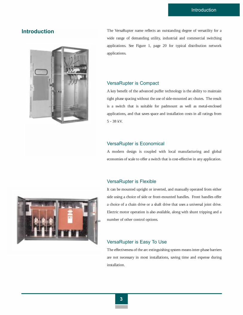
Introduction
The VersaRupter name reflects an outstanding degree of versatility for a
wide range of demanding utility, industrial and commercial switching
applications. See Figure 1, page 20 for typical distribution network
applications.
VersaRupter is Compact
A key benefit of the advanced puffer technology is the ability to maintain
tight phase spacing without the use of side-mounted arc chutes. The result
is a switch that is suitable for padmount as well as metal-enclosed
applications, and that saves space and installation costs in all ratings from
5 - 38 kV.
VersaRupter is Economical
A modern design is coupled with local manufacturing and global
economies of scale to offer a switch that is cost-effective in any application.
VersaRupter is Flexible
It can be mounted upright or inverted, and manually operated from either
side using a choice of side or front-mounted handles. Front handles offer
a choice of a chain drive or a shaft drive that uses a universal joint drive.
Electric motor operation is also available, along with shunt tripping and a
number of other control options.
VersaRupter is Easy To Use
The effectiveness of the arc extinguishing system means inter-phase barriers
are not necessary in most installations, saving time and expense during
installation.
Introduction

4
History
The arc extinguishing system is located at the fixed contact for each
phase. The system consists of an arcing contact mounted inside an arc-
extinguishing nozzle . This nozzle is supported by the same
insulator that supports the fixed main current-carrying contact. This
insulator also contains a small piston . During an opening operation,
the arcing blade is sequenced to open just after the main current-carrying
blades. As the arcing contact opens, the piston forces air through the
nozzle, efficiently extinguishing the arc and interrupting the load current.
The proprietary nozzle material further enhances the performance of the
arc system (see Figure 2 on page 21).
The durable VersaRupter switch is also known for superior quality and
proven reliability. Over 500,000 switches in this family are installed
worldwide in more than 50 countries, in a broad range of environments
from the North Sea to the deserts of the Equator. The VersaRupter is made
of materials selected to provide this superior durability and performance
(see Figure 3 on page 21). The chassis is fabricated from heavy gauge steel
with welded construction. The chassis is phosphate treated and painted
with baked-on, corrosion-resistant water base paint. The primary contacts
are copper and are insulated from the chassis with high strength, high
temperature insulators designed with excess phase-to-phase creepage
distance and minimum footprint. Current carrying components are
designed to withstand the specific rated continuous and momentary
current loads. The arc extinguishing system utilizes a high-grade
thermoplastic material with excellent dielectric properties. The complete
switch has been type tested on multiple occasions, with independent
agencies witnessing the tests.
VersaRupter meets the requirements of applicable ANSI and IEC
standards. The ability to meet the rigorous requirements of these multiple
standards provides switchgear assemblers with outstanding assurance of a
quality product, as well as flexibility and economy of design from using a
single switch for local and global switchgear applications. The switch is also
available with UL Listing in select 5-15.5 kV ratings.
Most VersaRupter switches are manufactured locally in a factory certified to
ISO-9001 and ISO-14000 standards. Local assembly and technical
support assures responsive customer service and prompt, on-time delivery
of the world's leading load interrupter switch.
12
3
4
5
6
1 Fixed (Main) Contact
Arcing Contact
Arc Extinguishing Nozzle
Support Insulator
Piston
Arcing Blade
2
3
4
5
6
1
2
3
4
5
6
History

5
Standard Features
The VersaRupter is a three-pole, single throw load break switch available in
ratings from 4.76 through 38 kV. Continuous and interrupting currents of
200, 600 and 1200 amps are available in ratings through 27 kV, and these
switches are provided with 40 kA momentary and fault closing capability.
The 38 kV switch has 600 amp continuous and interrupting current
ratings, and momentary and fault close ratings of 40 kA and 30 kA
respectively. The VersaRupter load break switch is also available in 15 kV
and 15.5 kV, 61 kA rating in 95 kV and 110 kV BIL respectively.
The basic load break switch includes the steel chassis, molded insulators,
current-carrying parts, arc blades and chambers, and a snap action or stored
energy operating mechanism.
A number of options are available, including a choice of snap action or
stored energy operating mechanisms, handle systems, interlocks, fuse bases,
and control features. Grounding switches are also available.
VersaRupter switch (open position) with K-Mechanism (snap action)
Standard Features

6
Fused Switches
Optional current limiting fuses provide the ability to interrupt short circuit
currents. A choice of fuse mounting kits or fuse bases are available. Both
options include mounting clips, and are available for installation on the
upper or lower side of the switch. Fuse mounting kits are compatible with
UL Listed type CL-14 fuses. Fuse bases are compatible with IEC type CEF
and CLF fuses. Contact the factory for availability of mounting kits and
clips for other types of fuses. The VersaRupter fuse base can also
incorporate optional automatic mechanical switch tripping. When a fuse
operates, a plunger actuates a mechanical linkage that trips a stored energy
operating mechanism. The mechanical fuse tripping option requires the
use of a stored energy type “A- Mechanism” (shown). An auxiliary switch
option (not shown) is also available to provide an indication or alarm when
the fuses are opened.
Fuse Options
Fuse Base
VersaRupter Switch
Fused Switches

7
Mechanisms
Operating Mechanisms
The K-Mechanism is a single spring, snap action device. The switch opens
or closes by charging the spring past dead center, using one of the manual
operating handles. The K-Mechanism also interfaces with an optional
motor operator for automatic opening or closing.
K-Mechanisms (Snap Action)
The A-Mechanism is a dual spring, stored energy device that is well-suited
for remote tripping applications. The opening spring is charged and
latched by an operating handle (direct or chain drive), or by a motor
operator. The switch is then opened by any of several methods:
• movement of the operating handle
• motor operator
• electrical signal to a shunt trip device
• mechanical fuse tripping linkage
A-Mechanisms
The KS-mechanism is a single spring, snap action device with a type S
latching system. This mechanism operates in the same manner as the
standard K-Mechanism, however, the switch is latched in the open or
closed position. The single spring is used for charging the device. When
the mechanism is latched, the switch is ready for release by a shunt trip or
mechanical fuse tripping linkage. The KS-Mechanism is also well suited
for remote trip applications. Note: Motor operator options are not
available for use with this mechanism.
KS-Mechanisms
(Snap Action with Latching)
The VersaRupter is available with a choice of snap action and stored energy
types of operating mechanisms for a wide variety of applications.

8
Motor Control
Motor Operators Motor operators enable automatic remote opening and closing of all
VersaRupter mechanisms, and spring charging for types A and KS
mechanisms. Motor operators do not interfere with manual operation
(except KS-Mechanism). Several styles of motor operators provide flexible
mounting configurations.
The A1 and A2 style motor operators can be installed on the right front or
left front of a VersaRupter enclosure, or adjacent to the left or right side of
the main operating shaft. The A1 and A2 motor can open and close the
switch with both A and K mechanisms when the operator is mounted to
the front of the cell. The device fits switches with both A and K
mechanisms and is connected by a universal joint.
The NM operator (shown) can be operated by local pushbutton or by
remote control. The design of the motor operator also allows for manual
switch operation. The NM operator can be mounted conveniently without
interfering with control cables or connectors.
VOLTAGE AC/DC 24 V 10% 48 V 10% 60 V 10% 110 V 10% 220 V 10%
Current, I A 3 3 0.8 0.8 0.4
Power consumption W 70 140 45 85 90
Operating time sec. ~4 ~2 ~8 ~4 ~4
Operating temperature oC -40 to +55 -40 to +55 -40 to +55 -40 to +55 -40 to +55
Signalling time sec. 0.5 - 2.0 0.3 - 1.0 1.0 - 4.0 0.5 - 2.0 0.5 - 2.0
Weight kg 6 6 6 6 6
NM Motor Operator Characteristics
+-
+-
+-
+-
+-

9
Motor Control
Remote mounted controllers are available for the A1 and NM style motor
operators. The A2 style motor operator includes a self-contained
controller. A complete range of AC and DC control voltages are available
for motor operation.
Motor Controllers
The NM operator can be directly mounted on the VersaRupter main
operating shaft (ALT. A & B), or adjacent to the right or left side of the
shaft (ALT. C & D). The NM Operator automatically synchronizes to the
proper position upon actuation of the mechanism. Shaft extensions are
available for left side or adjacent cell mounting.
Examples of Mounting Alternatives
A B
C D

10
Operating Handles
A Manual Operator Handle is available for shaft-mounted direct operation
of the VersaRupter from either side. The handles are available for fixed-
mount or removable applications. The left side handle requires a left-hand
shaft extension. Padlocking is available with the fixed mount handle.
Manual Handles
Chain Drive Handles mount at the front of the enclosure on the right or
left side. The handle case contains a sprocket connected by a chain drive
to another sprocket mounted on the main shaft. This arrangement
provides flexibility in handle mounting angle for various enclosure designs
and switch positions. The handle has provisions for key interlocking.
Chain Drive Handle
Fixed Mount
Removable
The wide choice of manual operating handles assures complete flexibility
for a variety of installations and mounting arrangements. In addition to
compatibility with direct side-drive handles, VersaRupter can be operated
from the left or right front with a choice of chain drives or type HE
operating shafts with universal joints.
Operating Handles

11
Operating Handles
Shaft Extension
Mechanical Door Interlock
Spline Tubes
This assembly provides front-mounted direct drive connection to the
switch main shaft. The HE Operator is recommended for front-mounted
manual or motor operator configurations. A bevel gear (upper photo) is
provided for connection to the switch shaft, and a universal joint (lower
photo) linkage is provided at the handle. The switchgear assembler provides
a shaft that connects the bevel gear with the universal joint. By allowing
for varying shaft lengths, the switchgear assembler can define the ultimate
position and distance to customize the enclosure. The type HE Operator
is available in a (locking) coupled style for manual operation, and a de-
coupled style for motor operation.
Type HE Operator
Optional Spline Tubes provide the ability to create shaft extensions,
customize operator handles, or link the mechanical actuation of switches
together. Two lengths are available.
Optional Shaft Extensions are available for left-hand operation, or for
adjacent mounting of Motor Operators or Manual Operator Handles.
Some shaft extensions may be grooved for cutoff to the precise required
length.
Mechanical Door Interlocks are available to prevent opening the enclosure
door when the switch is closed. Standard and Offset versions of the
Mechanical Door Interlock accommodate different door designs.
Other Handle Accessories
Front MountUniversal Joint
Assemblywith Shaft
Front Mounted Motorwith HE Operator
Bevel Gear

12
Grounding Switches
Type E Grounding Switches are available for grounding the hinged side of
the VersaRupter in a two-step operation. When the VersaRupter is open,
a mechanical interlock enables the ground switch to be closed using a
separate manual operator. The mechanical interlock prevents the
VersaRupter from being closed while the Grounding Switch is closed.
Grounding Switches mount to the switch chassis and fuse base. The
grounding switch is spring-loaded and provides a direct path to ground
when the switch and/or fuse is opened. The grounding switch springs
rotate three blade contacts, which engage the pivot side primary
connections. This device is typically used to direct residual energy stored
in the load side of the circuit to ground.
Mechanical Interlock between VersaRupter and grounding switch prevents
simultaneous closing of grounding switch and VersaRupter.
Grounding Switches - Type E
Mechanical Interlock

13
Electric Control Options
The optional Auxiliary Switch is available with six or eight contacts,
configured with an even number of normally open and normally closed
contacts. The Auxiliary Switch is mounted to the chassis and changes state
when the VersaRupter or grounding switch is opened or closed.
Auxiliary Switch
Shunt Trip operation is available for local push button or remote trip
applications. This device utilizes a solenoid to actuate the "A" or "KS"
mechanism trip latch. The Shunt Trip is available in a complete range of
AC and DC control voltages. Use of the shunt trip requires an auxiliary
switch (below) to assure momentary actuation of the shunt trip coil.
Shunt Trip
An optional Fuse Auxiliary Switch is available to indicate an open fuse
condition. This switch has two contacts, one normally open and one
normally closed, and is actuated by the tie rod linkage connected to the fuse
base.
Fuse Auxiliary Switch
A Number of Control Options...

14
Ratings
VersaRupter Load Break Switch RatingsSYSTEM VOLTAGE CURRENT SNAP STOREDRATING Rated Rated Low Rated Load Rated Fault ACTION ENERGY
kV Max. Dielectric Frequency Cont. Interrupt Mom. Cur. Close Cur. CATALOG CATALOGNOMINAL Voltage BIL Imp. Withstand Current Capacity Asym. A. Asym. NUMBER NUMBER
(kV) (kV) (kV) (Amperes) (Amperes) RMS (kA) RMS (kA)
4.73 200 200 244-040-502 245-864-501(Pole spacing: 8.25 75 26 600 600 40 40 244-040-506 245-864-502
5.9 inches) 1200 1200 244-040-510 245-864-503
12.0 thru 13.8 200 200 244-041-502 245-864-504(Pole spacing: 15 95 36 600 600 40 40 244-041-506 245-864-5056.69 inches) 1200 1200 244-041-510 245-864-506
12.0 thru 16.8 200 200 244-042-502 245-864-507(Pole spacing: 17 110 50 600 600 40 40 244-042-506 245-864-5089.25 inches) 1200 1200 244-042-510 245-864-511
22.9 thru 24.9 200 200 244-043-502 245-864-513(Pole spacing: 27 125 60 600 600 40 40 244-043-506 245-864-51410.8 inches) 1200 1200 244-043-510 245-864-517
34.5 600 600 244-005-501 245-864-519(Pole spacing: 38 150 80 800 800 40 30 244-005-502 245-864-520
14.1 inches)
13.8 600 600 245-881-506 245-881-514(Pole spacing: 15* 95 36 1200 1200 61 61 245-881-510 245-881-515
9.25 inches)
14.4 600 600 245-881-522 245-881-530(Pole spacing: 15.5* 110 50 1200 1200 61 61 245-881-526 245-881-531
9.25 inches)
UL Recognized VersaRupter Load Break SwitchesSYSTEM Rated RatedRATING Max. Cont. CATALOG
kV Voltage Current- NUMBERNOMINAL (kV) (Amps)
5 kV 200 244-040-512(Pole spacing: 5 600 244-040-515
5.9 inches)
15 kV 200 244-041-512(Pole spacing: 15 600 244-041-5156.69 inches)
*All 61kA VersaRupter UL and CSA approved
UL Recognized VersaRupter Switch Ratings5 kV Switches 15 kV Switches
Rated Max. kV 5 Rated Max. kV. 15
Rated Dielectric 60 Rated Dielectric 95BIL Impulse (kV) BIL Impulse (kV)
Low Frequency 19 Low Frequency 36Withstand (kV) Withstand (kV)
Rated Mom. 40 Rated Mom. 40kA Asym. ms. kA Asym. ms.
Fault Closing kA 40 Fault Closing kA 40Asym. ms Asym. ms
Ratings

Mechanism
15
Mounting
Example of Mounting of Switch with Fuse Base and Accessories
Auxiliary switch
Shaft extension forleft-hand operation
Mechanical interlocking
Grounding switch type E
Motor controller
HE-operation- lower part
(mounted in cell front)
Shunt trip
Auxiliary switch atopen fuse
Operator handle
HE-operation- upper part
1
2
3
4
5
6
7
8
9
10
11
1
2
3
4
5 11
6
7
8
9
10
Door Mounted Devices

16
Diagrams

17
Diagrams
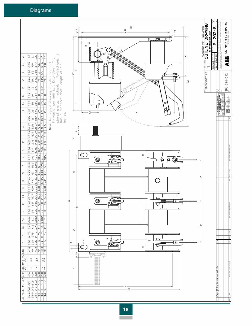
18
Diagrams

19
Diagram

20
Reference
Pad Mount
Distribution�Breakers
Primary �Entrance Unit
�Switchgear
PEU #1 PEU #2
Power Switching Center
Distribution Network Figure 1
Reference

Figure 3
2 3 4 5 6 7 8 9 1000 1 2 3 4 5
100
200
300
400
500
600
700
800
900
1000
N
1 (A)
1600A
21
Reference
Figure 2
Operating Sequence
1. In open position
2. Opening sequence
3. Interrupting sequence
4. Closed position
Curve 1 = Gas Blast
Curve 2 = Air Blast
Curve 3 = The resultant
extinguishing effect =
Curve 1+Curve 2
Number of load
operations of
VersaRupter switch
(12kV - 600A)
1
3
2
Breaking Current

655 Century PointLake Mary, FL 32746Tel: +1-407-723-2000
1-800-929-7947Fax: +1-407-732-2161www.abb.com/mediumvoltage
TG
2.2
.4.6
B
F
ebru
ary
2002
2300 Mechanicsville HighwayFlorence, SC 29501Tel: +1-843-413-4800
1-800-338-1585Fax: +1-843-413-4850www.abb.com/mediumvoltage