Verilog Tutorial - classweb.ece.umd.educlassweb.ece.umd.edu/enee359a/verilog_tutorial.pdf ·...
227
Verilog Tutorial By Deepak Kumar Tala http://www.asic-world.com 1
Transcript of Verilog Tutorial - classweb.ece.umd.educlassweb.ece.umd.edu/enee359a/verilog_tutorial.pdf ·...

Verilog TutorialBy
Deepak Kumar Tala
http://www.asic−world.com
1

DISCLAIMER
I don't makes any claims, promises or guarantees about the accuracy,completeness, or adequacy of the contents of this tutorial and
expressly disclaims liability for errors and omissions in the contents ofthis tutorial. No warranty of any kind, implied, expressed or statutory,
including but not limited to the warranties of non−infringement of thirdparty rights, title, merchantability, fitness for a particular purpose andfreedom from computer virus, is given with respect to the contents ofthis tutorial or its hyperlinks to other Internet resources. Reference in
this tutorial to any specific commercial products, processes, orservices, or the use of any trade, firm or corporation name is for the
information, and does not constitute endorsement, recommendation, orfavoring by me. All the source code and Tutorials are to be used on
your own risk. All the ideas and views in this tutorial are my own andare not by any means related to my employer.
www.asic−world.com 2

INTRODUCTIONCHAPTER 1
www.asic−world.com 3

IntroductionVerilog is a HARDWARE DESCRIPTION LANGUAGE (HDL). A hardware description Languageis a language used to describe a digital system, for example, a network switch, a microprocessoror a memory or a simple flip−flop. This just means that, by using a HDL one can describe anyhardware (digital ) at any level.
1// D flip−flop Code2module d_ff ( d, clk, q, q_bar);3input d ,clk;4output q, q_bar;5wire d ,clk;6reg q, q_bar;78always @ (posedge clk)9begin
10 q <= d;11 q_bar <= !d;12end1314endmodule
One can describe a simple Flip flop as that in above figure as well as one can describe acomplicated designs having 1 million gates. Verilog is one of the HDL languages available in theindustry for designing the Hardware. Verilog allows us to design a Digital design at Behavior Level,Register Transfer Level (RTL), Gate level and at switch level. Verilog allows hardware designers toexpress their designs with behavioral constructs, deterring the details of implementation to a laterstage of design in the final design.
Many engineers who want to learn Verilog, most often ask this question, how much time it will taketo learn Verilog?, Well my answer to them is "It may not take more then one week, if youhappen to know at least one programming language".
Design StylesVerilog like any other hardware description language, permits the designers to design a design ineither Bottom−up or Top−down methodology.
Bottom−Up Design
The traditional method of electronic design is bottom−up. Each design is performed at thegate−level using the standard gates ( Refer to the Digital Section for more details) With increasing
www.asic−world.com INTRODUCTION 4

complexity of new designs this approach is nearly impossible to maintain. New systems consist ofASIC or microprocessors with a complexity of thousands of transistors. These traditionalbottom−up designs have to give way to new structural, hierarchical design methods. Without thesenew design practices it would be impossible to handle the new complexity.
Top−Down Design
The desired design−style of all designers is the top−down design. A real top−down design allowsearly testing, easy change of different technologies, a structured system design and offers manyother advantages. But it is very difficult to follow a pure top−down design. Due to this fact mostdesigns are mix of both the methods, implementing some key elements of both design styles.
Figure shows a Top−Down design approach.
Abstraction Levels of VerilogVerilog supports a design at many different levels of abstraction. Three of them are very important:
Behavioral level•
www.asic−world.com INTRODUCTION 5

Register−Transfer Level• Gate Level•
Behavioral level
This level describes a system by concurrent algorithms (Behavioral). Each algorithm itself issequential, that means it consists of a set of instructions that are executed one after the other.Functions, Tasks and Always blocks are the main elements. There is no regard to the structuralrealization of the design.
Register−Transfer Level
Designs using the Register−Transfer Level specify the characteristics of a circuit by operationsand the transfer of data between the registers. An explicit clock is used. RTL design contains exacttiming possibility, operations are scheduled to occur at certain times. Modern definition of a RTLcode is "Any code that is synthesizable is called RTL code".
Gate Level
Within the logic level the characteristics of a system are described by logical links and their timingproperties. All signals are discrete signals. They can only have definite logical values (`0', `1', `X',`Z`). The usable operations are predefined logic primitives (AND, OR, NOT etc gates). Using gatelevel modeling might not be a good idea for any level of logic design. Gate level code is generatedby tools like synthesis tools and this netlist is used for gate level simulation and for backend.
www.asic−world.com INTRODUCTION 6

NOTES−−
−−
−−
−−
−−
−−
−−
−−
−−
−−
−−
−−
−−
−−
−−
−−
−−
−−
−−
−−
−−
−−
−−
−−
−−
−−
−−
−−
−−
−−
−−
−−
−−
−−
−−
−−
−−
−−
www.asic−world.com INTRODUCTION 7

HISTORY OF VERILOGCHAPTER 2
www.asic−world.com HISTORY OF VERILOG 8

History Of VerilogVerilog was started initially as a proprietary hardware modeling language by Gateway DesignAutomation Inc. around 1984. It is rumored that the original language was designed by takingfeatures from the most popular HDL language of the time, called HiLo as well as from traditionalcomputer language such as C. At that time, Verilog was not standardized and the languagemodified itself in almost all the revisions that came out within 1984 to 1990.
Verilog simulator was first used beginning in 1985 and was extended substantially through1987.The implementation was the Verilog simulator sold by Gateway. The first major extensionwas Verilog−XL, which added a few features and implemented the infamous "XL algorithm" whichwas a very efficient method for doing gate−level simulation.
The time was late 1990. Cadence Design System, whose primary product at that time includedThin film process simulator, decided to acquire Gateway Automation System. Along with otherGateway product, Cadence now became the owner of the Verilog language, and continued tomarket Verilog as both a language and a simulator. At the same time, Synopsys was marketing thetop−down design methodology, using Verilog. This was a powerful combination.
In 1990, Cadence recognized that if Verilog remained a closed language, the pressures ofstandardization would eventually cause the industry to shift to VHDL. Consequently, Cadenceorganized Open Verilog International (OVI), and in 1991 gave it the documentation for the VerilogHardware Description Language. This was the event which "opened" the language.
OVI did a considerable amount of work to improve the Language Reference Manual (LRM),clarifying things and making the language specification as vendor−independent as possible.
Soon it was realized, that if there were too many companies in the market for Verilog, potentiallyeverybody would like to do what Gateway did so far − changing the language for their own benefit.This would defeat the main purpose of releasing the language to public domain. As a result in1994, the IEEE 1364 working group was formed to turn the OVI LRM into an IEEE standard. Thiseffort was concluded with a successful ballot in 1995, and Verilog became an IEEE standard inDecember, 1995.
When Cadence gave OVI the LRM, several companies began working on Verilog simulators. In1992, the first of these were announced, and by 1993 there were several Verilog simulatorsavailable from companies other than Cadence. The most successful of these was VCS, the VerilogCompiled Simulator, from Chronologic Simulation. This was a true compiler as opposed to aninterpreter, which is what Verilog−XL was. As a result, compile time was substantial, but simulationexecution speed was much faster.
In the meantime, the popularity of Verilog and PLI was rising exponentially. Verilog as a HDL foundmore admirers than well−formed and federally funded VHDL. It was only a matter of time beforepeople in OVI realized the need of a more universally accepted standard. Accordingly, the board ofdirectors of OVI requested IEEE to form a working committee for establishing Verilog as an IEEEstandard. The working committee 1364 was formed in mid 1993 and on October 14, 1993, it had
www.asic−world.com HISTORY OF VERILOG 9

its first meeting.
The standard, which combined both the Verilog language syntax and the PLI in a single volume,was passed in May 1995 and now known as IEEE Std. 1364−1995.
After many years, new features have been added to Verilog, and new version is called Verilog2001. This version seems to have fixed lot of problems that Verilog 1995 had. This version iscalled 1364−2000. Only waiting now is that all the tool vendors implementing it.
www.asic−world.com HISTORY OF VERILOG 10

NOTES−−
−−
−−
−−
−−
−−
−−
−−
−−
−−
−−
−−
−−
−−
−−
−−
−−
−−
−−
−−
−−
−−
−−
−−
−−
−−
−−
−−
−−
−−
−−
−−
−−
−−
−−
−−
−−
−−
www.asic−world.com HISTORY OF VERILOG 11

DESIGN AND TOOL FLOWCHAPTER 3
www.asic−world.com DESIGN AND TOOL FLOW 12

IntroductionBeing new to Verilog you might want to try some examples and try designing something new. Ihave listed the tool flow that could be used to achieve this. I have personally tried this flow andfound this to be working just fine for me. Here I have taken only front end design part of the toolflow and bit of FPGA design flow that can be done without any fat money spent on tools. If youhave any suggestions or questions please don't hesitate to mail me. ( Note : I have missed stepsin P&R, Will add then shortly)
Various stages of ASIC/FPGA
Specification : Word processor like Word, Kwriter, AbiWord, Open Office.• High Level Design : Word processor like Word, Kwriter, AbiWord, for drawing waveformuse tools like waveformer or testbencher or Word, Open Office.
•
Micro Design/Low level design: Word processor like Word, Kwriter, AbiWord, for drawingwaveform use tools like waveformer or testbencher or Word. For FSM StateCAD or somesimilar tool, Open Office.
•
RTL Coding : Vim, Emacs, conTEXT, HDL TurboWriter• Simulation : Modelsim, VCS, Verilog−XL, Veriwell, Finsim, iVerilog, VeriDOS.• Synthesis : Design Compiler, FPGA Compiler, Synplify, Leonardo Spectrum. You candownload this from FPGA vendors like Altera and Xilinx for free.
•
Place & Route : For FPGA use FPGA' vendors P&R tool. ASIC tools require expensiveP&R tools like Apollo. Students can use LASI, Magic.
•
Post Si Validation : For ASIC and FPGA, the chip needs to be tested in real environment.Board design, device drivers needs to be in place.
•
Figure : Typical Design flow
www.asic−world.com DESIGN AND TOOL FLOW 13

Specification
This is the stage at which we define what are the important parameters of the system/design thatyou are planning to design. Simple example would be, like I want to design a counter, it should be4 bit wide, should have synchronous reset, with active high enable, When reset is active, counteroutput should go to "0". You can use Microsoft Word, or GNU Abiword or Openoffice for enteringthe specification.
High Level Design
This is the stage at which you define various blocks in the design and how they communicate. Letsassume that we need to design microprocessor, High level design means splitting the design intoblocks based on their function, In our case various blocks are registers, ALU, Instruction Decode,Memory Interface, etc. You can use Microsoft Word, or KWriter or Abiword or Openoffice forentering high level design.
www.asic−world.com DESIGN AND TOOL FLOW 14

Figure : I8155 High Level Block Diagram
Micro Design/Low level design
Low level design or Micro design is the phase in which, designer describes how each block isimplemented. It contains details of State machines, counters, Mux, decoders, internal registers.For state machine entry you can use either Word, or special tools like StateCAD. It is always agood idea if waveform is drawn at various interfaces. This is phase, where one spends lot of time.
Figure : Sample Low level design
RTL Coding
In RTL coding, Micro Design is converted into Verilog/VHDL code, using synthesizable constructsof the language. Normally we use vim editor, but I prefer conTEXT and Nedit editor, it all dependson which editor you like. Some use Emacs.
1module addbit (2a , // first input3b , // Second input4ci , // Carry input5sum , // sum output6co // carry output7);8//Input declaration
www.asic−world.com DESIGN AND TOOL FLOW 15

9input a;10input b;11input ci;12//Ouput declaration13output sum;14output co;15//Port Data types16wire a;17wire b;18wire ci;19wire sum;20wire co;21//Code starts here22assign {co,sum} = a + b + ci;2324endmodule // End of Module addbit
Figure : Sample RTL code
Simulation
Simulation is the process of verifying the functional characteristics of models at any level ofabstraction. We use simulators to simulate the the Hardware models. To test if the RTL codemeets the functional requirements of the specification, see if all the RTL blocks are functionallycorrect. To achieve this we need to write testbench, which generates clk, reset and required testvectors. A sample testbench for a counter is as shown below. Normally we spend 60−70% of timein verification of design.
Figure : Sample Testbench Env
We use waveform output from the simulator to see if the DUT (Device Under Test) is functionallycorrect. Most of the simulators comes with waveform viewer, As design becomes complex, wewrite self checking testbench, where testbench applies the test vector, compares the output ofDUT with expected value.
There is another kind of simulation, called timing simulation, which is done after synthesis orafter P&R (Place and Route). Here we include the gate delays and wire delays and see if DUTworks at rated clock speed. This is also called as SDF simulation or gate level simulation.
www.asic−world.com DESIGN AND TOOL FLOW 16

Figure : 4 bit Up Counter Waveform
Synthesis
Synthesis is process in which synthesis tool like design compiler or Synplify takes the RTL inVerilog or VHDL, target technology, and constrains as input and maps the RTL to targettechnology primitives. Synthesis tool after mapping the RTL to gates, also do the minimal amountof timing analysis to see if the mapped design meeting the timing requirements. ( Important thingto note is, synthesis tools are not aware of wire delays, they know only gate delays). After thesynthesis there are couple of things that are normally done before passing the netlist to backend(Place and Route)
Formal Verification : Check if the RTL to gate mapping is correct.• Scan insertion : Insert the scan chain in the case of ASIC.•
Figure : Synthesis Flow
Place & Route
Gatelevel netlist from the synthesis tool is taken and imported into place and route tool in Verilognetlist format. All the gates and flip−flops are places, Clock tree synthesis and reset is routed. Afterthis each block is routed. Output of the P&R tool is GDS file, this files is used by foundry forfabricating the ASIC. Normally the P&R tool are used to output the SDF file, which is backannotated along with the gatelevel netlist from P&R into static analysis tool like Prime Time to dotiming analysis.
www.asic−world.com DESIGN AND TOOL FLOW 17

Figure : Sample micro−processor placement
Figure : J−K Flip−Flop
Post Silicon Validation
Once the chip (silicon) is back from fab, it needs to put in real environment and tested before it canbe released into Market. Since the speed of simulation with RTL is very slow (number clocks persecond), there is always possibility to find a bug in Post silicon validation.
www.asic−world.com DESIGN AND TOOL FLOW 18

NOTES−−
−−
−−
−−
−−
−−
−−
−−
−−
−−
−−
−−
−−
−−
−−
−−
−−
−−
−−
−−
−−
−−
−−
−−
−−
−−
−−
−−
−−
−−
−−
−−
−−
−−
−−
−−
−−
−−
www.asic−world.com DESIGN AND TOOL FLOW 19

MY FIRST PROGRAM IN VERILOGCHAPTER 4
www.asic−world.com MY FIRST PROGRAM IN VERILOG 20

IntroductionIf you refer to any book on programming language it starts with "hello World" program, once you
have written the program, you can be sure that you can do something in that language .
Well I am also going to show how to write a "hello world" program in Verilog, followed by"counter" design in Verilog.
Hello World Program
1//−−−−−−−−−−−−−−−−−−−−−−−−−−−−−−−−−−−−−−−−−−−−−−−−−−−−−2// This is my first Verilog Program3// Design Name : hello_world4// File Name : hello_world.v5// Function : This program will print 'hello world'6// Coder : Deepak7//−−−−−−−−−−−−−−−−−−−−−−−−−−−−−−−−−−−−−−−−−−−−−−−−−−−−−8module hello_world ;9
10initial begin11 $display ( "Hello World by Deepak" );12 #10 $finish;13end1415endmodule // End of Module hello_world
Words in green are comments, blue are reserved words, Any program in Verilog starts withreserved word module , In the above example line 7 contains module hello_world. (Note: We canhave compiler pre−processor statements like `include, `define statements before moduledeclaration)
Line 9 contains the initial block, this block gets executed only once after the simulation starts andat time=0 (0ns). This block contains two statements, which are enclosed within begin at line 7 andend at line 12. In Verilog if you have multiple lines within a block, you need to use begin and end.
Hello World Program Output
Hello World by Deepak
Counter Design Block
www.asic−world.com MY FIRST PROGRAM IN VERILOG 21
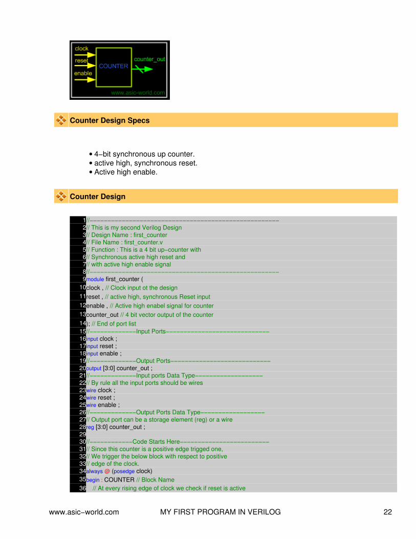
Counter Design Specs
4−bit synchronous up counter.• active high, synchronous reset.• Active high enable.•
Counter Design
1//−−−−−−−−−−−−−−−−−−−−−−−−−−−−−−−−−−−−−−−−−−−−−−−−−−−−−2// This is my second Verilog Design3// Design Name : first_counter4// File Name : first_counter.v5// Function : This is a 4 bit up−counter with6// Synchronous active high reset and7// with active high enable signal8//−−−−−−−−−−−−−−−−−−−−−−−−−−−−−−−−−−−−−−−−−−−−−−−−−−−−−9module first_counter (
10clock , // Clock input ot the design11reset , // active high, synchronous Reset input12enable , // Active high enabel signal for counter13counter_out // 4 bit vector output of the counter14); // End of port list15//−−−−−−−−−−−−−Input Ports−−−−−−−−−−−−−−−−−−−−−−−−−−−−−16input clock ;17input reset ;18input enable ;19//−−−−−−−−−−−−−Output Ports−−−−−−−−−−−−−−−−−−−−−−−−−−−−20output [3:0] counter_out ;21//−−−−−−−−−−−−−Input ports Data Type−−−−−−−−−−−−−−−−−−−22// By rule all the input ports should be wires23wire clock ;24wire reset ;25wire enable ;26//−−−−−−−−−−−−−Output Ports Data Type−−−−−−−−−−−−−−−−−−27// Output port can be a storage element (reg) or a wire28reg [3:0] counter_out ;2930//−−−−−−−−−−−−Code Starts Here−−−−−−−−−−−−−−−−−−−−−−−−−31// Since this counter is a positive edge trigged one,32// We trigger the below block with respect to positive33// edge of the clock.34always @ (posedge clock)35begin : COUNTER // Block Name36 // At every rising edge of clock we check if reset is active
www.asic−world.com MY FIRST PROGRAM IN VERILOG 22

37 // If active, we load the counter output with 4'b000038 if (reset == 1'b1) begin
39 counter_out <= #1 4'b0000;40 end
41 // If enable is active, then we increment the counter42 else if (enable == 1'b1) begin
43 counter_out <= #1 counter_out + 1;44 end
45end // End of Block COUNTER4647endmodule // End of Module counter
Counter Test Bench
Any digital circuit, not matter how complex it is needs to be tested. For the counter logic, we needto provide clock, reset logic. Once counter is out of reset we toggle the enable input to counter,and check with waveform to see if counter is counting correctly. We do the same in Verilog.
Counter testbench consists of clock generator, reset control, enable control and compare logic.Below is the simple code of testbench without the compare logic.
1`include "first_counter.v"2module first_counter_tb();3// Declare inputs as regs and outputs as wires4reg clock, reset, enable;5wire [3:0] counter_out;67// Initialize all variables8initial begin9 $display ( "time\t clk reset enable counter" );
10 $monitor ( "%g\t %b %b %b %b" ,11 $time, clock, reset, enable, counter_out);12 clock = 1; // initial value of clock
www.asic−world.com MY FIRST PROGRAM IN VERILOG 23

13 reset = 0; // initial value of reset14 enable = 0; // initial value of enable15 #5 reset = 1; // Assert the reset16 #10 reset = 0; // De−assert the reset17 #5 enable = 1; // Assert enable18 #100 enable = 0; // De−assert enable19 #10 $finish; // Terminate simulation20end2122// Clock generator23always begin24 #5 clock = ~clock; // Toggle clock every 5 ticks25end2627// Connect DUT to test bench28first_counter U_counter (29clock,30reset,31enable,32counter_out33);3435endmodule
time clk reset enable counter 0 1 0 0 xxxx 5 0 1 0 xxxx 10 1 1 0 xxxx 11 1 1 0 0000 15 0 0 0 0000 20 1 0 1 0000 21 1 0 1 0001 25 0 0 1 0001 30 1 0 1 0001 31 1 0 1 0010 35 0 0 1 0010 40 1 0 1 0010 41 1 0 1 0011 45 0 0 1 0011 50 1 0 1 0011 51 1 0 1 0100 55 0 0 1 0100 60 1 0 1 0100 61 1 0 1 0101 65 0 0 1 0101 70 1 0 1 0101 71 1 0 1 0110 75 0 0 1 0110 80 1 0 1 0110 81 1 0 1 0111 85 0 0 1 0111 90 1 0 1 0111 91 1 0 1 1000 95 0 0 1 1000 100 1 0 1 1000 101 1 0 1 1001 105 0 0 1 1001 110 1 0 1 1001 111 1 0 1 1010
www.asic−world.com MY FIRST PROGRAM IN VERILOG 24

115 0 0 1 1010 120 1 0 0 1010 125 0 0 0 1010
Counter Waveform
www.asic−world.com MY FIRST PROGRAM IN VERILOG 25

NOTES−−
−−
−−
−−
−−
−−
−−
−−
−−
−−
−−
−−
−−
−−
−−
−−
−−
−−
−−
−−
−−
−−
−−
−−
−−
−−
−−
−−
−−
−−
−−
−−
−−
−−
−−
−−
−−
−−
www.asic−world.com MY FIRST PROGRAM IN VERILOG 26
VERILOG HDL SYNTAX AND SEMANTICSCHAPTER 5
www.asic−world.com VERILOG HDL SYNTAX AND SEMANTICS 27
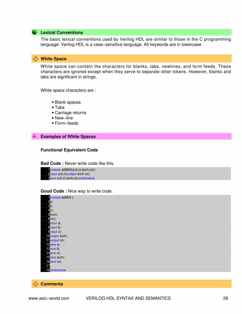
Lexical ConventionsThe basic lexical conventions used by Verilog HDL are similar to those in the C programminglanguage. Verilog HDL is a case−sensitive language. All keywords are in lowercase.
White Space
White space can contain the characters for blanks, tabs, newlines, and form feeds. Thesecharacters are ignored except when they serve to separate other tokens. However, blanks andtabs are significant in strings.
White space characters are :
Blank spaces• Tabs• Carriage returns• New−line• Form−feeds•
Examples of White Spaces
Functional Equivalent Code
Bad Code : Never write code like this.1module addbit(a,b,ci,sum,co);2input a,b,ci;output sum co;3wire a,b,ci,sum,co;endmodule
Good Code : Nice way to write code.1module addbit (2a,3b,4ci,5sum,6co);7input a;8input b;9input ci;
10output sum;11output co;12wire a;13wire b;14wire ci;15wire sum;16wire co;1718endmodule
Comments
www.asic−world.com VERILOG HDL SYNTAX AND SEMANTICS 28

There are two forms to introduce comments.
Single line comments begin with the token // and end with a carriage return• Multi Line comments begin with the token /* and end with the token */•
Some how I like single line comments.
Examples of Comments
1/* This is a2Multi line comment3example */4module addbit (5a,6b,7ci,8sum,9co);
1011// Input Ports Single line comment12input a;13input b;14input ci;15// Output ports16output sum;17output co;18// Data Types19wire a;20wire b;21wire ci;22wire sum;23wire co;2425endmodule
Case Sensitivity
Verilog HDL is case sensitive
Lower case letters are unique from upper case letters• All Verilog keywords are lower case•
Examples of Unique names
1input // a Verilog Keyword2wire // a Verilog Keyword3WIRE // a unique name ( not a keyword)4Wire // a unique name (not a keyword)
www.asic−world.com VERILOG HDL SYNTAX AND SEMANTICS 29

NOTE : Never use the Verilog keywords as unique name, even if the case is different.
Identifiers
Identifiers are names used to give an object, such as a register or a function or a module, a nameso that it can be referenced from other places in a description.
Identifiers must begin with an alphabetic character or the underscore character (a−z A−Z _)
•
Identifiers may contain alphabetic characters, numeric characters, the underscore, and thedollar sign (a−z A−Z 0−9 _ $ )
•
Identifiers can be up to 1024 characters long.•
Examples of legal identifiersdata_input muclk_input my$clki386 A
Escaped Identifiers
Verilog HDL allows any character to be used in an identifier by escaping the identifier. Escapedidentifiers provide a means of including any of the printable ASCII characters in an identifier (thedecimal values 33 through 126, or 21 through 7E in hexadecimal).
Escaped identifiers begin with the back slash ( \ )• Entire identifier is escaped by the back slash.• Escaped identif ier is terminated by white space (Characters such as commas,parentheses, and semicolons become part of the escaped identifier unless preceded by awhite space)
•
Terminate escaped identifiers with white space, otherwise characters that should follow theidentifier are considered as part of it.
•
Examples of escape identifiersVerilog does not allow to identifier to start with a numeric character. So if you really wan to use aidentifier to start with a numeric value then use a escape character as shown below.
1// There must be white space after the2// string which uses escape character3module \1dff (4q, // Q output5\q~ , // Q_out output6d, // D input7cl$k, // CLOCK input8\reset* // Reset input9);
www.asic−world.com VERILOG HDL SYNTAX AND SEMANTICS 30

1011input d, cl$k, \reset* ;12output q, \q~ ;1314endmodule
Numbers in VerilogYou can specify constant numbers in decimal, hexadecimal, octal, or binary format. Negativenumbers are represented in 2's complement form. When used in a number, the question mark (?)character is the Verilog alternative for the z character. The underscore character (_) is legalanywhere in a number except as the first character, where it is ignored.
Integer Numbers
Verilog HDL allows integer numbers to be specified as
Sized or unsized numbers ( Unsized size is 32 bits )• In a radix of binary, octal, decimal, or hexadecimal• Radix and hex digits (a,b,c,d,e,f) are case insensitive• Spaces are allowed between the size, radix and value•
Syntax: <size>'<radix> <value>
Example of Integer Numbers
Integer Stored as
1 00000000000000000000000000000001
8'hAA 10101010
6'b10_0011 100011
'hF 00000000000000000000000000001111
Verilog expands to be fill the specified by working from right−to−left
When is smaller than , then left−most bits of are truncated• When is larger than , then left−most bits are filled, based on the value of the left−most bit in.
•
Left most '0' or '1' are filled with '0'♦ Left most 'Z' are filled with 'Z'♦ Left most 'X' are filled with 'X'♦
Example of Integer Numbers
www.asic−world.com VERILOG HDL SYNTAX AND SEMANTICS 31
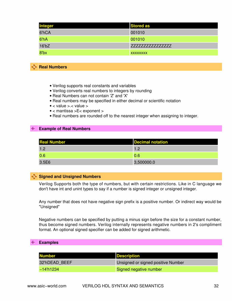
Integer Stored as
6'hCA 001010
6'hA 001010
16'bZ ZZZZZZZZZZZZZZZZ
8'bx xxxxxxxx
Real Numbers
Verilog supports real constants and variables• Verilog converts real numbers to integers by rounding• Real Numbers can not contain 'Z' and 'X'• Real numbers may be specified in either decimal or scientific notation• < value >.< value >• < mantissa >E< exponent >• Real numbers are rounded off to the nearest integer when assigning to integer.•
Example of Real Numbers
Real Number Decimal notation
1.2 1.2
0.6 0.6
3.5E6 3,500000.0
Signed and Unsigned Numbers
Verilog Supports both the type of numbers, but with certain restrictions. Like in C language wedon't have int and unint types to say if a number is signed integer or unsigned integer.
Any number that does not have negative sign prefix is a positive number. Or indirect way would be"Unsigned"
Negative numbers can be specified by putting a minus sign before the size for a constant number,thus become signed numbers. Verilog internally represents negative numbers in 2's complimentformat. An optional signed specifier can be added for signed arithmetic.
Examples
Number Description
32'hDEAD_BEEF Unsigned or signed positive Number
−14'h1234 Signed negative number
www.asic−world.com VERILOG HDL SYNTAX AND SEMANTICS 32

Below example file show how Verilog treats signed and unsigned numbers.1//******************************************2// Signed Number Example3//4// Written by Deepak Kumar Tala5//******************************************6module signed_number;78reg [31:0] a;9
10initial begin11 a = 14'h1234;12 $display ( "Current Value of a = %h" , a);13 a = −14'h1234;14 $display ( "Current Value of a = %h" , a);15 a = 32'hDEAD_BEEF;16 $display ( "Current Value of a = %h" , a);17 a = −32'hDEAD_BEEF;18 $display ( "Current Value of a = %h" , a);19 #10 $finish;20end2122endmodule
Current Value of a = 00001234 Current Value of a = ffffedcc Current Value of a = deadbeef Current Value of a = 21524111
Modules
Module are the building blocks of Verilog designs• You create design hierarchy by instantiating modules in other modules.• An instance of a module is a use of that module in another, higher−level module.•
www.asic−world.com VERILOG HDL SYNTAX AND SEMANTICS 33

Ports
Ports allow communication between a module and its environment.• All but the top−level modules in a hierarchy have ports.• Ports can be associated by order or by name.•
You declare ports to be input, output or inout. The port declaration syntax is :input [range_val:range_var] list_of_identifiers;output [range_val:range_var] list_of_identifiers;inout [range_val:range_var] list_of_identifiers;
NOTE : As a good coding practice, there should be only one port identifier per line, as shownbelow
Examples : Port Declaration
1input clk ; // clock input2input [15:0] data_in ; // 16 bit data input bus3output [7:0] count ; // 8 bit counter output4inout data_bi ; // Bi−Directional data bus
Examples : A complete Example in Verilog
www.asic−world.com VERILOG HDL SYNTAX AND SEMANTICS 34

1module addbit (2a , // first input3b , // Second input4ci , // Carry input5sum , // sum output6co // carry output7);8//Input declaration9input a;
10input b;11input ci;12//Ouput declaration13output sum;14output co;15//Port Data types16wire a;17wire b;18wire ci;19wire sum;20wire co;21//Code starts here22assign {co,sum} = a + b + ci;2324endmodule // End of Module addbit
Modules connected by port order (implicit)Here order should match correctly. Normally it not a good idea to connect ports implicit. Couldcause problem in debug (locate the port which is causing compiler compile error), when any newport is added or deleted.
1//−−−−−−−−−−−−−−−−−−−−−−−−−−−−−−−−−−−−−−−−−−−−−−−−−−−−−2// This is simple adder Program3// Design Name : adder_implicit4// File Name : adder_implicit.v5// Function : This program shows how implicit6// port connection are done7// Coder : Deepak8//−−−−−−−−−−−−−−−−−−−−−−−−−−−−−−−−−−−−−−−−−−−−−−−−−−−−−9module adder_implicit (
10result , // Output of the adder11carry , // Carry output of adder12r1 , // first input13r2 , // second input14ci // carry input15);1617// Input Port Declarations18input [3:0] r1 ;19input [3:0] r2 ;20input ci ;2122// Output Port Declarations23output [3:0] result ;24output carry ;2526// Port Wires
www.asic−world.com VERILOG HDL SYNTAX AND SEMANTICS 35

27wire [3:0] r1 ;28wire [3:0] r2 ;29wire ci ;30wire [3:0] result ;31wire carry ;3233// Internal variables34wire c1 ;35wire c2 ;36wire c3 ;3738// Code Starts Here39addbit u0 (40r1[0] ,41r2[0] ,42ci ,43result[0] ,44c145);4647addbit u1 (48r1[1] ,49r2[1] ,50c1 ,51result[1] ,52c253);5455addbit u2 (56r1[2] ,57r2[2] ,58c2 ,59result[2] ,60c361);6263addbit u3 (64r1[3] ,65r2[3] ,66c3 ,67result[3] ,68carry69);7071endmodule // End Of Module adder
Modules connect by nameHere the name should match with the leaf module, the order is not important.
1//−−−−−−−−−−−−−−−−−−−−−−−−−−−−−−−−−−−−−−−−−−−−−−−−−−−−−2// This is simple adder Program3// Design Name : adder_implicit4// File Name : adder_implicit.v5// Function : This program shows how explicit6// port connection are done7// Coder : Deepak8//−−−−−−−−−−−−−−−−−−−−−−−−−−−−−−−−−−−−−−−−−−−−−−−−−−−−−9module adder_explicit (
10result , // Output of the adder
www.asic−world.com VERILOG HDL SYNTAX AND SEMANTICS 36

11carry , // Carry output of adder12r1 , // first input13r2 , // second input14ci // carry input15);1617// Input Port Declarations18input [3:0] r1 ;19input [3:0] r2 ;20input ci ;2122// Output Port Declarations23output [3:0] result ;24output carry ;2526// Port Wires27wire [3:0] r1 ;28wire [3:0] r2 ;29wire ci ;30wire [3:0] result ;31wire carry ;3233// Internal variables34wire c1 ;35wire c2 ;36wire c3 ;3738// Code Starts Here3940// Code Starts Here4142addbit u0 (43.a (r1[0]) ,44.b (r2[0]) ,45.ci (ci) ,46.sum (result[0]) ,47.co (c1)48);4950addbit u1 (51.a (r1[1]) ,52.b (r2[1]) ,53.ci (c1) ,54.sum (result[1]) ,55.co (c2)56);5758addbit u2 (59.a (r1[2]) ,60.b (r2[2]) ,61.ci (c2) ,62.sum (result[2]) ,63.co (c3)64);6566addbit u3 (67.a (r1[3]) ,68.b (r2[3]) ,69.ci (c3) ,70.sum (result[3]) ,71.co (carry)
www.asic−world.com VERILOG HDL SYNTAX AND SEMANTICS 37

72);7374endmodule // End Of Module adder
Instantiating a module
1//−−−−−−−−−−−−−−−−−−−−−−−−−−−−−−−−−−−−−−−−−−−−−−−−−−−−−2// This is simple parity Program3// Design Name : parity4// File Name : parity.v5// Function : This program shows how a verilog6// primitive/module port connection are7// done8// Coder : Deepak9//−−−−−−−−−−−−−−−−−−−−−−−−−−−−−−−−−−−−−−−−−−−−−−−−−−−−−
10module parity (11a , // First input12b , // Second input13c , // Third Input14d , // Fourth Input15y // Parity output16);1718// Input Declaration19input a ;20input b ;21input c ;22input d ;23// Ouput Declaration24output y ;25// port data types26wire a ;27wire b ;28wire c ;29wire d ;30wire y ;31// Internal variables32wire out_0 ;33wire out_1 ;3435// Code starts Here36xor u0 (37out_0 ,38a ,39b40);4142xor u1 (43out_1 ,44c ,45d46);4748xor u2 (49y ,50out_0 ,51out_152);
www.asic−world.com VERILOG HDL SYNTAX AND SEMANTICS 38

5354endmodule // End Of Module parity
Question : What is difference between u0 in module adder and u0 in module parity?
Schematic
Port Connection Rules
Inputs : internally must always be type net, externally the inputs can be connected tovariable reg or net type.
•
Outputs : internally can be type net or reg, externally the outputs must be connected to avariable net type.
•
Inouts : internally or externally must always be type net, can only be connected to avariable net type.
•
Width matching : It is legal to connect internal and external ports of different sizes. Butbeware, synthesis tools could report problems.
•
Unconnected ports : unconnected ports are allowed by using a ","• The net data types are used to connect structure• A net data type is required if a signal can be driven a structural connection.•
Example − Implicit
dff u0 ( q,,clk,d,rst,pre); // Here second port is not connected
www.asic−world.com VERILOG HDL SYNTAX AND SEMANTICS 39

Example − Explicit
dff u0 (.q (q_out),.q_bar (),.clk (clk_in),.d (d_in),.rst (rst_in),.pre (pre_in)); // Here second port is not connected
Hierarchical IdentifiersHierarchical path names are based on the top module identifier followed by module instantidentifiers, separated by periods.
This is basically useful, while we want to see the signal inside a lower module or want to force avalue on to internal module. Below example shows hows to monitor the value of internal modulesignal.
Example
1//−−−−−−−−−−−−−−−−−−−−−−−−−−−−−−−−−−−−−−−−−−−−−−−−−−−−−2// This is simple adder Program3// Design Name : adder_hier4// File Name : adder_hier.v5// Function : This program shows verilog hier path works6// Coder : Deepak7//−−−−−−−−−−−−−−−−−−−−−−−−−−−−−−−−−−−−−−−−−−−−−−−−−−−−−8`include "addbit.v"9module adder_hier (
10result , // Output of the adder11carry , // Carry output of adder12r1 , // first input13r2 , // second input14ci // carry input15);1617// Input Port Declarations18input [3:0] r1 ;19input [3:0] r2 ;20input ci ;2122// Output Port Declarations23output [3:0] result ;24output carry ;
www.asic−world.com VERILOG HDL SYNTAX AND SEMANTICS 40

2526// Port Wires27wire [3:0] r1 ;28wire [3:0] r2 ;29wire ci ;30wire [3:0] result ;31wire carry ;3233// Internal variables34wire c1 ;35wire c2 ;36wire c3 ;3738// Code Starts Here39addbit u0 (r1[0],r2[0],ci,result[0],c1);40addbit u1 (r1[1],r2[1],c1,result[1],c2);41addbit u2 (r1[2],r2[2],c2,result[2],c3);42addbit u3 (r1[3],r2[3],c3,result[3],carry);4344endmodule // End Of Module adder4546module tb();4748reg [3:0] r1,r2;49reg ci;50wire [3:0] result;51wire carry;5253// Drive the inputs54initial begin55 r1 = 0;56 r2 = 0;57 ci = 0;58 #10 r1 = 10;59 #10 r2 = 2;60 #10 ci = 1;61 #10 $display( "+−−−−−−−−−−−−−−−−−−−−−−−−−−−−−−−−−−−−−−−−−−−−−−−−−−−−−−−−+" );62 $finish;63end6465// Connect the lower module66adder_hier U (result,carry,r1,r2,ci);6768// Hier demo here69initial begin70 $display( "+−−−−−−−−−−−−−−−−−−−−−−−−−−−−−−−−−−−−−−−−−−−−−−−−−−−−−−−−+" );71 $display( "| r1 | r2 | ci | u0.sum | u1.sum | u2.sum | u3.sum |" );72 $display( "+−−−−−−−−−−−−−−−−−−−−−−−−−−−−−−−−−−−−−−−−−−−−−−−−−−−−−−−−+" );73 $monitor( "| %h | %h | %h | %h | %h | %h | %h |" ,74 r1,r2,ci, tb.U.u0.sum, tb.U.u1.sum, tb.U.u2.sum, tb.U.u3.sum);75end7677endmodule
+−−−−−−−−−−−−−−−−−−−−−−−−−−−−−−−−−−−−−−−−−−−−−−−−−−−−−−−−+ | r1 | r2 | ci | u0.sum | u1.sum | u2.sum | u3.sum | +−−−−−−−−−−−−−−−−−−−−−−−−−−−−−−−−−−−−−−−−−−−−−−−−−−−−−−−−+ | 0 | 0 | 0 | 0 | 0 | 0 | 0 |
www.asic−world.com VERILOG HDL SYNTAX AND SEMANTICS 41

| a | 0 | 0 | 0 | 1 | 0 | 1 | | a | 2 | 0 | 0 | 0 | 1 | 1 | | a | 2 | 1 | 1 | 0 | 1 | 1 | +−−−−−−−−−−−−−−−−−−−−−−−−−−−−−−−−−−−−−−−−−−−−−−−−−−−−−−−−+
Data TypesVerilog Language has two primary data types
Nets − represents structural connections between components.• Registers − represent variables used to store data.•
Every signal has a data type associated with it:
Explicitly declared with a declaration in your Verilog code.• Implicitly declared with no declaration but used to connect structural building blocks inyour code.
•
Implicit declaration is always a net type "wire" and is one bit wide.•
Types of Nets
Each net type has functionality that is used to model different types of hardware (such as PMOS,NMOS, CMOS, etc)
Net Data Type Functionality
wire, tri Interconnecting wire − no special resolution function
wor, trior Wired outputs OR together (models ECL)
wand,triand Wired outputs AND together (models open−collector)
tri0,tri1 Net pulls−down or pulls−up when not driven
supply0,suppy1 Net has a constant logic 0 or logic 1 (supply strength)
trireg
Note : Of all the net types, wire is the one which is most widely used
Register Data Types
Registers store the last value assigned to them until another assignment statementchanges their value.
•
Registers represent data storage constructs.• You can create arrays of the regs called memories.• register data types are used as variables in procedural blocks.• A register data type is required if a signal is assigned a value within a procedural block•
www.asic−world.com VERILOG HDL SYNTAX AND SEMANTICS 42

Procedural blocks begin with keyword initial and always.•
Data Types Functionality
reg Unsigned variable
integer Signed variable − 32 bits
time Unsigned integer − 64 bits
real Double precision floating point variable
Note : Of all the register types, reg is the one which is most widely used
StringsA string is a sequence of characters enclosed by double quotes and all contained on a single line.Strings used as operands in expressions and assignments are treated as a sequence of eight−bitASCII values, with one eight−bit ASCII value representing one character. To declare a variable tostore a string, declare a register large enough to hold the maximum number of characters thevariable will hold. Note that no extra bits are required to hold a termination character; Verilog doesnot store a string termination character. Strings can be manipulated using the standard operators.
When a variable is larger than required to hold a value being assigned, Verilog pads the contentson the left with zeros after the assignment. This is consistent with the padding that occurs duringassignment of non−string values.
Certain characters can be used in strings only when preceded by an introductory character calledan escape character. The following table lists these characters in the right−hand column with theescape sequence that represents the character in the left−hand column.
Special Characters in Strings
Character Description
\n New line character
\t Tab character
\\ Backslash (\) character
\" Double quote (") character
\ddd A character specified in 1−3 octal digits (0 <= d <= 7)
%% Percent (%) character
Example
www.asic−world.com VERILOG HDL SYNTAX AND SEMANTICS 43

1//−−−−−−−−−−−−−−−−−−−−−−−−−−−−−−−−−−−−−−−−−−−−−−−−−−−−−2// Design Name : strings3// File Name : strings.v4// Function : This program shows how string5// can be stored in reg6// Coder : Deepak Kumar Tala7//−−−−−−−−−−−−−−−−−−−−−−−−−−−−−−−−−−−−−−−−−−−−−−−−−−−−−8module strings();9// Declare a register variable that is 21 bytes
10reg [8*21:0] string ;1112initial begin13 string = "This is sample string" ;14 $display ( "%s \n" , string);15end1617endmodule
This is sample string
www.asic−world.com VERILOG HDL SYNTAX AND SEMANTICS 44

NOTES−−
−−
−−
−−
−−
−−
−−
−−
−−
−−
−−
−−
−−
−−
−−
−−
−−
−−
−−
−−
−−
−−
−−
−−
−−
−−
−−
−−
−−
−−
−−
−−
−−
−−
−−
−−
−−
−−
www.asic−world.com VERILOG HDL SYNTAX AND SEMANTICS 45

GATE LEVEL MODELINGCHAPTER 6
www.asic−world.com GATE LEVEL MODELING 46

IntroductionVerilog has built in primitives like gates, transmission gates, and switches. This are rarely used forin design work, but are used in post synthesis world for modeling the ASIC/FPGA cells, this cellsare then used for gate level simulation or what is called as SDF simulation. Also the output netlistformate from the synthesis tool which is imported into place and route tool is also in Verilog gatelevel primitives.
Gate Primitives
The gates have one scalar output and multiple scalar inputs. The 1st terminal in the list of gateterminals is an output and the other terminals are inputs.
Gate Description
and N−input AND gate
nand N−input NAND gate
or N−input OR gate
nor N−input NOR gate
xor N−input XOR gate
xnor N−input XNOR gate
Examples
1module gates();23wire out0;4wire out1;5wire out2;6reg in1,in2,in3,in4;78not U1(out0,in1);9and U2(out1,in1,in2,in3,in4);
10xor U3(out2,in1,in2,in3);1112initial begin
www.asic−world.com GATE LEVEL MODELING 47

13$monitor( "in1 = %b in2 = %b in3 = %b in4 = %b out0 = %b out1 = %b out2 = %b",in1,in2,in3,in4,out0,out1,out2);
14 in1 = 0;15 in2 = 0;16 in3 = 0;17 in4 = 0;18 #1 in1 = 1;19 #1 in2 = 1;20 #1 in3 = 1;21 #1 in4 = 1;22 #1 $finish;23end2425endmodule
in1 = 0 in2 = 0 in3 = 0 in4 = 0 out0 = 1 out1 = 0 out2 = 0 in1 = 1 in2 = 0 in3 = 0 in4 = 0 out0 = 0 out1 = 0 out2 = 1 in1 = 1 in2 = 1 in3 = 0 in4 = 0 out0 = 0 out1 = 0 out2 = 0 in1 = 1 in2 = 1 in3 = 1 in4 = 0 out0 = 0 out1 = 0 out2 = 1 in1 = 1 in2 = 1 in3 = 1 in4 = 1 out0 = 0 out1 = 1 out2 = 1
Transmission Gate Primitives
Gate Description
not N−output inverter
buf N−output buffer.
bufif0 Tri−state buffer, Active low en.
bufif1 Tri−state buffer, Active high en.
notif0 Tristate inverter, Low en.
notif1 Tristate inverter, High en.
Examples
www.asic−world.com GATE LEVEL MODELING 48

1module transmission_gates();23reg data_enable_low, in;4wire data_bus, out1, out2;56bufif0 U1(data_bus,in, data_enable_low);7buf U2(out1,in);8not U3(out2,in);9
10initial begin11 $monitor( "in = %b data_enable_low = %b out1 = %b out2 = %b" ,in,data_enable_low, out1, out2);12 data_enable_low = 0;13 in = 0;14 #4 data_enable_low = 1;15 #8 $finish;16end1718always #2 in = ~in;1920endmodule
in = 0 data_enable_low = 0 out1 = 0 out2 = 1 in = 1 data_enable_low = 0 out1 = 1 out2 = 0 in = 0 data_enable_low = 1 out1 = 0 out2 = 1 in = 1 data_enable_low = 1 out1 = 1 out2 = 0 in = 0 data_enable_low = 1 out1 = 0 out2 = 1 in = 1 data_enable_low = 1 out1 = 1 out2 = 0
Switch Primitives
www.asic−world.com GATE LEVEL MODELING 49

Gate Description
1. pmos Uni−directional PMOS switch
1. rpmos Resistive PMOS switch
2. nmos Uni−directional NMOS switch
2. rnmos Resistive NMOS switch
3. cmos Uni−directional CMOS switch
3. rcmos Resistive CMOS switch
4. tranif1 Bi−directional transistor (High)
4. tranif0 Bi−directional transistor (Low)
5. rtranif1 Resistive Transistor (High)
5. rtranif0 Resistive Transistor (Low)
6. tran Bi−directional pass transistor
6. rtran Resistive pass transistor
7. pullup Pull up resistor
8. pulldown Pull down resistor
Transmission gates are bi−directional and can be resistive or non−resistive.
Syntax: keyword unique_name (inout1, inout2, control);
Examples
1module switch_primitives();23wire net1, net2, net3;4wire net4, net5, net6;56tranif0 my_gate1 (net1, net2, net3);7rtranif1 my_gate2 (net4, net5, net6);89endmodule
Transmission gates tran and rtran are permanently on and do not have a control line. Tran can beused to interface two wires with separate drives, and rtran can be used to weaken signals.Resistive devices reduce the signal strength which appears on the output by one level. All theswitches only pass signals from source to drain, incorrect wiring of the devices will result in highimpedance outputs.
Logic Values and signal StrengthsThe Verilog HDL has got four logic values
www.asic−world.com GATE LEVEL MODELING 50

Logic Value Description
0 zero, low, false
1 one, high, true
z or Z high impedance, floating
x or X unknown, uninitialized, contention
Verilog Strength Levels
Strength Level Specification Keyword
7 Supply Drive supply0 supply1
6 Strong Pull strong0 strong1
5 Pull Drive pull0 pull1
4 Large Capacitance large
3 Weak Drive weak0 weak1
2 Medium Capacitance medium
1 Small Capacitance small
0 Hi Impedance highz0 highz1
Example
Two buffers that has outputA : Pull 1B : Supply 0Since supply 0 is stronger then pull 1, Output C takes value of B.
Example
www.asic−world.com GATE LEVEL MODELING 51

Two buffers that has outputA : Supply 1B : Large 1Since Supply 1 is stronger then Large 1, Output C takes the value of A
Designing Using PrimitivesDesigning using primitives is used only in library development, where the ASIC vendor providesthe ASIC library verilog description using verilog primitives and user defines primitives (UDP).
AND Gate from NAND Gate
Code
1// Structural model of AND gate from two NANDS2module and_from_nand();34reg X, Y;5wire F, W;6// Two instantiations of the module NAND7nand U1(W,X, Y);8nand U2(F, W, W);9
10// Testbench Code11initial begin12 $monitor ( "X = %b Y = %b F = %b" , X, Y, F);13 X = 0;14 Y = 0;15 #1 X = 1;
www.asic−world.com GATE LEVEL MODELING 52

16 #1 Y = 1;17 #1 X = 0;18 #1 $finish;19end2021endmodule
X = 0 Y = 0 F = 0 X = 1 Y = 0 F = 0 X = 1 Y = 1 F = 1 X = 0 Y = 1 F = 0
D−Flip flop from NAND Gate
Verilog Code
1module dff_from_nand();2wire Q,Q_BAR;3reg D,CLK;45nand U1 (X,D,CLK) ;6nand U2 (Y,X,CLK) ;7nand U3 (Q,Q_BAR,X);8nand U4 (Q_BAR,Q,Y);9
10// Testbench of above code11initial begin12 $monitor( "CLK = %b D = %b Q = %b Q_BAR = %b" ,CLK, D, Q, Q_BAR);13 CLK = 0;14 D = 0;15 #3 D = 1;16 #3 D = 0;17 #3 $finish;18end1920always #2 CLK = ~CLK;2122endmodule
www.asic−world.com GATE LEVEL MODELING 53

CLK = 0 D = 0 Q = x Q_BAR = x CLK = 1 D = 0 Q = 0 Q_BAR = 1 CLK = 1 D = 1 Q = 1 Q_BAR = 0 CLK = 0 D = 1 Q = 1 Q_BAR = 0 CLK = 1 D = 0 Q = 0 Q_BAR = 1 CLK = 0 D = 0 Q = 0 Q_BAR = 1
Multiplexer from primitives
Verilog Code
1module mux_from_gates ();2reg c0,c1,c2,c3,A,B;3wire Y;4//Invert the sel signals5not (a_inv, A);6not (b_inv, B);7// 3−input AND gate8and (y0,c0,a_inv,b_inv);9and (y1,c1,a_inv,B);
10and (y2,c2,A,b_inv);11and (y3,c3,A,B);12// 4−input OR gate13or (Y, y0,y1,y2,y3);1415// Testbench Code goes here16initial begin17 $monitor ( "c0 = %b c1 = %b c2 = %b c3 = %b A = %b B = %b Y = %b" , c0, c1, c2, c3, A, B, Y);18 c0 = 0;
www.asic−world.com GATE LEVEL MODELING 54

19 c1 = 0;20 c2 = 0;21 c3 = 0;22 A = 0;23 B = 0;24 #1 A = 1;25 #2 B = 1;26 #4 A = 0;27 #8 $finish;28end2930always #1 c0 = ~c0;31always #2 c1 = ~c1;32always #3 c2 = ~c2;33always #4 c3 = ~c3;3435endmodule
c0 = 0 c1 = 0 c2 = 0 c3 = 0 A = 0 B = 0 Y = 0 c0 = 1 c1 = 0 c2 = 0 c3 = 0 A = 1 B = 0 Y = 0 c0 = 0 c1 = 1 c2 = 0 c3 = 0 A = 1 B = 0 Y = 0 c0 = 1 c1 = 1 c2 = 1 c3 = 0 A = 1 B = 1 Y = 0 c0 = 0 c1 = 0 c2 = 1 c3 = 1 A = 1 B = 1 Y = 1 c0 = 1 c1 = 0 c2 = 1 c3 = 1 A = 1 B = 1 Y = 1 c0 = 0 c1 = 1 c2 = 0 c3 = 1 A = 1 B = 1 Y = 1 c0 = 1 c1 = 1 c2 = 0 c3 = 1 A = 0 B = 1 Y = 1 c0 = 0 c1 = 0 c2 = 0 c3 = 0 A = 0 B = 1 Y = 0 c0 = 1 c1 = 0 c2 = 1 c3 = 0 A = 0 B = 1 Y = 0 c0 = 0 c1 = 1 c2 = 1 c3 = 0 A = 0 B = 1 Y = 1 c0 = 1 c1 = 1 c2 = 1 c3 = 0 A = 0 B = 1 Y = 1 c0 = 0 c1 = 0 c2 = 0 c3 = 1 A = 0 B = 1 Y = 0 c0 = 1 c1 = 0 c2 = 0 c3 = 1 A = 0 B = 1 Y = 0 c0 = 0 c1 = 1 c2 = 0 c3 = 1 A = 0 B = 1 Y = 1
Gate and Switch delaysIn real circuits , logic gates haves delays associated with them. Verilog provides the mechanism toassociate delays with gates.
Rise, Fall and Turn−off delays.• Minimal, Typical, and Maximum delays.•
Rise Delay
The rise delay is associated with a gate output transition to 1 from another value (0,x,z).
www.asic−world.com GATE LEVEL MODELING 55

Fall Delay
The fall delay is associated with a gate output transition to 0 from another value (1,x,z).
Turn−off Delay
The Turn−off delay is associated with a gate output transition to z from another value (0,1,x).
Min Value
The min value is the minimum delay value that the gate is expected to have.
Typ Value
The typ value is the typical delay value that the gate is expected to have.
Max Value
The max value is the maximum delay value that the gate is expected to have.
Examples
www.asic−world.com GATE LEVEL MODELING 56

1module delay_example();23wire out1,out2,out3,out4,out5,out6;4reg b,c;56// Delay for all transitions7or #5 u_or (out1,b,c);8// Rise and fall delay9and #(1,2) u_and (out2,b,c);
10// Rise, fall and turn off delay11nor #(1,2,3) u_nor (out3,b,c);12//One Delay, min, typ and max13nand #(1:2:3) u_nand (out4,b,c);14//Two delays, min,typ and max15buf #(1:4:8,4:5:6) u_buf (out5,b);16//Three delays, min, typ, and max17notif1 #(1:2:3,4:5:6,7:8:9) u_notif1 (out6,b,c);1819//Testbench code20initial begin
21 $monitor ( "Time = %g b = %b c=%b out1=%b out2=%b out3=%b out4=%b out5=%b out6=%b" , $time, b, c ,out1, out2, out3, out4, out5, out6);
22 b = 0;23 c = 0;24 #10 b = 1;25 #10 c = 1;26 #10 b = 0;27 #10 $finish;28end2930endmodule
Time = 0 b = 0 c=0 out1=x out2=x out3=x out4=x out5=x out6=x Time = 1 b = 0 c=0 out1=x out2=x out3=1 out4=x out5=x out6=x Time = 2 b = 0 c=0 out1=x out2=0 out3=1 out4=1 out5=x out6=z Time = 5 b = 0 c=0 out1=0 out2=0 out3=1 out4=1 out5=0 out6=z Time = 8 b = 0 c=0 out1=0 out2=0 out3=1 out4=1 out5=0 out6=z Time = 10 b = 1 c=0 out1=0 out2=0 out3=1 out4=1 out5=0 out6=z Time = 12 b = 1 c=0 out1=0 out2=0 out3=0 out4=1 out5=0 out6=z Time = 14 b = 1 c=0 out1=0 out2=0 out3=0 out4=1 out5=1 out6=z Time = 15 b = 1 c=0 out1=1 out2=0 out3=0 out4=1 out5=1 out6=z Time = 20 b = 1 c=1 out1=1 out2=0 out3=0 out4=1 out5=1 out6=z Time = 21 b = 1 c=1 out1=1 out2=1 out3=0 out4=1 out5=1 out6=z Time = 22 b = 1 c=1 out1=1 out2=1 out3=0 out4=0 out5=1 out6=z Time = 25 b = 1 c=1 out1=1 out2=1 out3=0 out4=0 out5=1 out6=0 Time = 30 b = 0 c=1 out1=1 out2=1 out3=0 out4=0 out5=1 out6=0 Time = 32 b = 0 c=1 out1=1 out2=0 out3=0 out4=1 out5=1 out6=1 Time = 35 b = 0 c=1 out1=1 out2=0 out3=0 out4=1 out5=0 out6=1
Gate Delay Code Example
www.asic−world.com GATE LEVEL MODELING 57

1module buf_gate ();2reg in;3wire out;45buf #(5) (out,in);67initial begin8 $monitor ( "Time = %g in = %b out=%b" , $time, in, out);9 in = 0;
10 #10 in = 1;11 #10 in = 0;12 #10 $finish;13end1415endmodule
Time = 0 in = 0 out=x Time = 5 in = 0 out=0 Time = 10 in = 1 out=0 Time = 15 in = 1 out=1 Time = 20 in = 0 out=1 Time = 25 in = 0 out=0
Gate Delay Code Example
1module buf_gate1 ();2reg in;3wire out;45buf #(2,3) (out,in);67initial begin8 $monitor ( "Time = %g in = %b out=%b" , $time, in, out);9 in = 0;
10 #10 in = 1;11 #10 in = 0;12 #10 $finish;13end1415endmodule
www.asic−world.com GATE LEVEL MODELING 58

Time = 0 in = 0 out=x Time = 3 in = 0 out=0 Time = 10 in = 1 out=0 Time = 12 in = 1 out=1 Time = 20 in = 0 out=1 Time = 23 in = 0 out=0
Gate Delay Code Example
1module delay();2reg in;3wire rise_delay, fall_delay, all_delay;45initial begin
6 $monitor ( "Time = %g in = %b rise_delay = %b fall_delay = %b all_delay = %b" , $time, in, rise_delay, fall_delay,all_delay);
7 in = 0;8 #10 in = 1;9 #10 in = 0;
10 #20 $finish;11end1213buf #(1,0)U_rise (rise_delay,in);14buf #(0,1)U_fall (fall_delay,in);15buf #1 U_all (all_delay,in);1617endmodule
Time = 0 in = 0 rise_delay = 0 fall_delay = x all_delay = x Time = 1 in = 0 rise_delay = 0 fall_delay = 0 all_delay = 0 Time = 10 in = 1 rise_delay = 0 fall_delay = 1 all_delay = 0 Time = 11 in = 1 rise_delay = 1 fall_delay = 1 all_delay = 1 Time = 20 in = 0 rise_delay = 0 fall_delay = 1 all_delay = 1 Time = 21 in = 0 rise_delay = 0 fall_delay = 0 all_delay = 0
www.asic−world.com GATE LEVEL MODELING 59

N−Input PrimitivesThe and, nand, or, nor, xor, and xnor primitives have one output and any number of inputs
The single output is the first terminal• All other terminals are inputs•
Examples
1module n_in_primitive();23wire out1,out2,out3;4reg in1,in2,in3,in4;56// Two input AND gate7and u_and1 (out1, in1, in2);8// four input AND gate9and u_and2 (out2, in1, in2, in3, in4);
10// three input XNOR gate11xnor u_xnor1 (out3, in1, in2, in3);1213//Testbench Code14initial begin
15 $monitor ( "in1 = %b in2 = %b in3 = %b in4 = %b out1 = %b out2 = %b out3 = %b" , in1, in2, in3, in4, out1, out2,out3);
16 in1 = 0;17 in2 = 0;18 in3 = 0;19 in4 = 0;20 #1 in1 = 1;21 #1 in2 = 1;22 #1 in3 = 1;23 #1 in4 = 1;24 #1 $finish;25end2627endmodule
in1 = 0 in2 = 0 in3 = 0 in4 = 0 out1 = 0 out2 = 0 out3 = 1 in1 = 1 in2 = 0 in3 = 0 in4 = 0 out1 = 0 out2 = 0 out3 = 0 in1 = 1 in2 = 1 in3 = 0 in4 = 0 out1 = 1 out2 = 0 out3 = 1 in1 = 1 in2 = 1 in3 = 1 in4 = 0 out1 = 1 out2 = 0 out3 = 0 in1 = 1 in2 = 1 in3 = 1 in4 = 1 out1 = 1 out2 = 1 out3 = 0
www.asic−world.com GATE LEVEL MODELING 60

N−Output PrimitivesThe buf and not primitives have any number of outputs and one input
The output are in first terminals listed.• The last terminal is the single input.•
Examples
1module n_out_primitive();23wire out,out_0,out_1,out_2,out_3,out_a,out_b,out_c;4wire in;56// one output Buffer gate7buf u_buf0 (out,in);8// four output Buffer gate9buf u_buf1 (out_0, out_1, out_2, out_3, in);
10// three output Invertor gate11not u_not0 (out_a, out_b, out_c, in);1213endmodule
www.asic−world.com GATE LEVEL MODELING 61

NOTES−−
−−
−−
−−
−−
−−
−−
−−
−−
−−
−−
−−
−−
−−
−−
−−
−−
−−
−−
−−
−−
−−
−−
−−
−−
−−
−−
−−
−−
−−
−−
−−
−−
−−
−−
−−
−−
−−
www.asic−world.com GATE LEVEL MODELING 62

USER DEFINED PRIMITIVESCHAPTER 7
www.asic−world.com USER DEFINED PRIMITIVES 63

IntroductionVerilog has built in primitives like gates, transmission gates, and switches. This is rather smallnumber of primitives, if we need more complex primitives, then Verilog provides UDP, or simplyUser Defined Primitives. Using UDP we can model
Combinational Logic• Sequention Logic•
We can include timing information along with this UDP to model complete ASIC library models.
Syntax
UDP begins with reserve word primitive and ends with endprimitive. This should follow byports/terminals of primitive. This is kind of same as we do for module definition. UDP's should bedefined outside module and endmodule
1//This code shows how input/output ports2// and primitve is declared3primitive udp_syntax (4a, // Port a5b, // Port b6c, // Port c7d // Port d8);9output a;
10input b,c,d;1112// UDP function code here1314endprimitive
In the above code, udp_syntax is the primitive name, it contains ports a, b,c,d.
The formal syntax of the UDP definition is as follows
<UDP> ::= primitive <name_of_UDP> ( <output_terminal_name>, <input_terminal_name> <,<input_terminal_name>>* ) ; <UDP_declaration>+ <UDP_initial_statement>? <table_definition> endprimitive
<name_of_UDP> ::= <IDENTIFIER>
<UDP_declaration> ::= <UDP_output_declaration> ||= <reg_declaration> ||= <UDP_input_declaration>
www.asic−world.com USER DEFINED PRIMITIVES 64

<UDP_output_declaration> ::= output <output_terminal _name>;<reg_declaration> ::= reg <output_terminal_name> ;
<UDP_input_declaration> ::= input <input_terminal_name> <,<input_terminal_name>>* ;
<UDP_initial_statement> ::= initial <output_terminal_name> = <init_val> ;
<init_val> ::= 1'b0 ||= 1'b1 ||= 1'bx ||= 1 ||= 0
<table_definition> ::= table <table_entries> endtable
<table_entries> ::= <combinational_entry>+ ||= <sequential_entry>+
<combinational_entry> ::= <level_input_list> : <OUTPUT_SYMBOL> ;
<sequential_entry> ::= <input_list> : <state> : <next_state> ;
<input_list> ::= <level_input_list> ||= <edge_input_list>
<level_input_list> ::= <LEVEL_SYMBOL>+
<edge_input_list> ::= <LEVEL_SYMBOL>* <edge> <LEVEL_SYMBOL>*
<edge> ::= ( <LEVEL_SYMBOL> <LEVEL_SYMBOL> ) ||= <EDGE_SYMBOL>
<state> ::= <LEVEL_SYMBOL>
<next_state> ::= <OUTPUT_SYMBOL> ||= −
UDP ports rules
A UDP can contain only one output and up to 10 inputs max.• Output Port should be the first port followed by one or more input ports.• All UDP ports are scalar, i.e. Vector ports are not allowed.•
www.asic−world.com USER DEFINED PRIMITIVES 65

UDP's can not have bidirectional ports.• The output terminal of a sequential UDP requires an additional declaration as type reg.• It is illegal to declare a reg for the output terminal of a combinational UDP•
Body
Functionality of primitive (both combinational and sequential) is described inside a table, and itends with reserve word endtable as shown in code below. For sequential UDP, we can use initialto assign initial value to output.
1// This code shows how UDP body looks like2primitive udp_body (3a, // Port a4b, // Port b5c // Port c6);7output a;8input b,c;9
10// UDP function code here11// A = B | C;12table
13 // B C : A14 ? 1 : 1;15 1 ? : 1;16 0 0 : 0;17endtable1819endprimitive
Note: A UDP cannot use 'z' in input table
TestBench to Check above UDP1`include "udp_body.v"2module udp_body_tb();34reg b,c;5wire a;67udp_body udp (a,b,c);89initial begin
10 $monitor( " B = %b C = %b A = %b" ,b,c,a);11 b = 0;12 c = 0;13 #1 b = 1;14 #1 b = 0;15 #1 c = 1;16 #1 b = 1'bx;17 #1 c = 0;18 #1 b = 1;19 #1 c = 1'bx;
www.asic−world.com USER DEFINED PRIMITIVES 66

20 #1 b = 0;21 #1 $finish;22end2324endmodule
Simulator Output
B = 0 C = 0 A = 0 B = 1 C = 0 A = 1 B = 0 C = 0 A = 0 B = 0 C = 1 A = 1 B = x C = 1 A = 1 B = x C = 0 A = x B = 1 C = 0 A = 1 B = 1 C = x A = 1 B = 0 C = x A = x
TableTable is used for describing the function of UDP. Verilog reserve world table marks the start oftable and reserve word endtable marks the end of table.
Each line inside a table is one condition, as and when a input changes, the input condition ismatched and the output is evaluated to reflect the new change in input.
initialinitial statement is used for initialization of sequential UDP's. This statement begins with thekeyword initial. The statement that follows must be an assignment statement that assigns a singlebit literal value to the output terminal reg.
1primitive udp_initial (a,b,c);2output a;3input b,c;4reg a;5// a has value of 1 at start of sim6initial a = 1'b1;78table
9 // udp_initial behaviour10endtable1112endprimitive
Symbols
UDP uses special symbols to describe functions, like rising edge, don't care so on. Below tableshows the symbols that are used in UDP's
www.asic−world.com USER DEFINED PRIMITIVES 67

Symbol Interpretation Explanation
? 0 or 1 or X ? means the variable can be 0 or 1 or x
b 0 or 1 Same as ?, but x is not included
f (10) Falling edge on an input
r (01) Rising edge on an input
p (01) or (0x) or (x1) or (1z) or (z1) Rising edge including x and z
n (10) or (1x) or (x0) or (0z) or (z0) Falling edge including x and z
* (??) All transitions
− no change No Change
We will see them in detail in next few pages.
Combinational UDPs
In combinational UDPs, the output is determined as a function of the current input. Whenever aninput changes value, the UDP is evaluated and one of the state table rows is matched. The outputstate is set to the value indicated by that row. This is kind of same as condition statements, eachline in table is one condition.
Combinational UDPs have one field per input and one field for the output. Input fields and outputfields are separated with colon. Each row of the table is terminated by a semicolon. For example,the following state table entry specifies that when the three inputs are all 0, the output is 0.
1primitive udp_combo (.....);23table
4 0 0 0 : 0;5 ...6endtable78endprimitive
The order of the inputs in the state table description must correspond to the order of the inputs inthe port list in the UDP definition header. It is not related to the order of the input declarations.
Each row in the table defines the output for a particular combination of input states. If all inputs arespecified as x, then the output must be specified as x. All combinations that are not explicitlyspecified result in a default output state of x.
ExampleIn below example entry, the ? represents a don't−care condition. This symbol indicates iterativesubstitution of 1, 0, and x. The table entry specifies that when the inputs are 0 and 1, the output is
www.asic−world.com USER DEFINED PRIMITIVES 68

1 no matter what the value of the current state is.
You do not have to explicitly specify every possible input combination. All combinations that arenot explicitly specified result in a default output state of x.
It is illegal to have the same combination of inputs, specified for different outputs.
1// This code shows how UDP body looks like2primitive udp_body (3a, // Port a4b, // Port b5c // Port c6);7output a;8input b,c;9
10// UDP function code here11// A = B | C;12table
13 // B C : A14 ? 1 : 1;15 1 ? : 1;16 0 0 : 0;17endtable1819endprimitive
TestBench to Check above UDP
1`include "udp_body.v"2module udp_body_tb();34reg b,c;5wire a;67udp_body udp (a,b,c);89initial begin
10 $monitor( " B = %b C = %b A = %b" ,b,c,a);11 b = 0;12 c = 0;13 #1 b = 1;14 #1 b = 0;15 #1 c = 1;16 #1 b = 1'bx;17 #1 c = 0;18 #1 b = 1;19 #1 c = 1'bx;20 #1 b = 0;21 #1 $finish;22end
www.asic−world.com USER DEFINED PRIMITIVES 69

2324endmodule
Simulator Output
B = 0 C = 0 A = 0 B = 1 C = 0 A = 1 B = 0 C = 0 A = 0 B = 0 C = 1 A = 1 B = x C = 1 A = 1 B = x C = 0 A = x B = 1 C = 0 A = 1 B = 1 C = x A = 1 B = 0 C = x A = x
Level Senstive Sequential UDP
Level−sensitive sequential behavior is represented the same way as combinational behavior,except that the output is declared to be of type reg, and there is an additional field in each tableentry. This new field represents the current state of the UDP.
The output is declared as reg to indicate that there is an internal state. The output value ofthe UDP is always the same as the internal state.
•
A field for the current state has been added. This field is separated by colons from theinputs and the output.
•
Sequential UDPs have an additional field inserted between the input fields and the output field,compared to combinational UDP. This additional field represents the current state of the UDP andis considered equivalent to the current output value. It is delimited by colons.
1primitive udp_seq (.....);23table
4 0 0 0 : 0 : 0;5 ...6endtable78endprimitive
Example
www.asic−world.com USER DEFINED PRIMITIVES 70

1primitive udp_latch(q, clk, d) ;2output q;3input clk, d;45reg q;67table
8 //clk d q q+9 0 1 : ? : 1 ;
10 0 0 : ? : 0 ;11 1 ? : ? : − ;12endtable1314endprimitive
Edge−Sensitive UDPs
In level−sensitive behavior, the values of the inputs and the current state are sufficient todetermine the output value. Edge−sensitive behavior differs in that changes in the output aretriggered by specific transitions of the inputs.
As in the combinational and the level−sensitive entries, a ? implies iteration of the entry over thevalues 0, 1, and x. A dash (−) in the output column indicates no value change.
All unspecified transitions default to the output value x. Thus, in the previous example, transition ofclock from 0 to x with data equal to 0 and current state equal to 1 result in the output q going to x.
All transitions that should not affect the output must be explicitly specified. Otherwise, they willcause the value of the output to change to x. If the UDP is sensitive to edges of any input, thedesired output state must be specified for all edges of all inputs.
Example
1primitive udp_sequential(q, clk, d);2output q;3input clk, d;45reg q;67table
8 // obtain output on rising edge of clk9 // clk d q q+
10 (01) 0 : ? : 0 ;11 (01) 1 : ? : 1 ;12 (0?) 1 : 1 : 1 ;13 (0?) 0 : 0 : 0 ;14 // ignore negative edge of clk15 (?0) ? : ? : − ;16 // ignore d changes on steady clk17 ? (??) : ? : − ;18endtable
www.asic−world.com USER DEFINED PRIMITIVES 71

1920endprimitive
Example UDP with initial
1primitive udp_sequential_initial(q, clk, d);2output q;3input clk, d;45reg q;67initial begin8 q = 0;9end
1011table
12 // obtain output on rising edge of clk13 // clk d q q+14 (01) 0 : ? : 0 ;15 (01) 1 : ? : 1 ;16 (0?) 1 : 1 : 1 ;17 (0?) 0 : 0 : 0 ;18 // ignore negative edge of clk19 (?0) ? : ? : − ;20 // ignore d changes on steady clk21 ? (??) : ? : − ;22endtable2324endprimitive
www.asic−world.com USER DEFINED PRIMITIVES 72

NOTES−−
−−
−−
−−
−−
−−
−−
−−
−−
−−
−−
−−
−−
−−
−−
−−
−−
−−
−−
−−
−−
−−
−−
−−
−−
−−
−−
−−
−−
−−
−−
−−
−−
−−
−−
−−
−−
−−
www.asic−world.com USER DEFINED PRIMITIVES 73

VERILOG OPERATORSCHAPTER 8
www.asic−world.com VERILOG OPERATORS 74

Arithmetic Operators
Binary: +, −, *, /, % (the modulus operator)• Unary: +, − (This is used to specify the sign)• Integer division truncates any fractional part• The result of a modulus operation takes the sign of the first operand• If any operand bit value is the unknown value x, then the entire result value is x• Register data types are used as unsigned values (Negative numbers are stored in two¿scomplement form)
•
Example
1module arithmetic_operators();23initial begin4 $display ( " 5 + 10 = %d" , 5 + 10);5 $display ( " 5 − 10 = %d" , 5 − 10);6 $display ( " 10 − 5 = %d" , 10 − 5);7 $display ( " 10 * 5 = %d" , 10 * 5);8 $display ( " 10 / 5 = %d" , 10 / 5);9 $display ( " 10 / −5 = %d" , 10 / −5);
10 $display ( " 10 %s 3 = %d" ,11 $display ( " +5 = %d" , +5);12 $display ( " −5 = %d" , −5);13 #10 $finish;14end1516endmodule
5 + 10 = 15 5 − 10 = −5 10 − 5 = 5 10 * 5 = 50 10 / 5 = 2 10 / −5 = −2 10 % 3 = 1 +5 = 5 −5 = −5
Relational Operators
Operator Description
a a less than b
a>b a greater than b
a<=b a less than or equal to b
a>=b a greater than or equal to b
www.asic−world.com VERILOG OPERATORS 75

The result is a scalar value:• 0 if the relation is false• 1 if the relation is true• x if any of the operands has unknown x bits•
Note: If a value is x or z, then the result of that test is false (0)
Example
1module relational_operators();23initial begin4 $display ( " 5 <= 10 = %b" , (5 <= 10));5 $display ( " 5 >= 10 = %b" , (5 >= 10));6 $display ( " 1'bx <= 10 = %b" , (1'bx <= 10));7 $display ( " 1'bz <= 10 = %b" , (1'bz <= 10));8 #10 $finish;9end
1011endmodule
5 <= 10 = 1 5 >= 10 = 0 1'bx <= 10 = 1 1'bz <= 10 = 1
Equality OperatorsThere are two types of Equality operators. Case Equality and Logical Equality.
Operator Description
a === b a equal to b, including x and z (Case equality)
a !== b a not equal to b, including x and z (Case inequality)
a == b a equal to b, resulting may be unknown (logical equality)
a != b a not equal to b, result may be unknown (logical equality)
Operands are compared bit by bit, with zero filling if the two operands do not have thesame length
•
Result is 0 (false) or 1 (true)• For the == and != operators the result is x, if either operand contains an x or a z• For the === and !== operators bits with x and z are included in the comparison and mustmatch for the result to be true
•
www.asic−world.com VERILOG OPERATORS 76
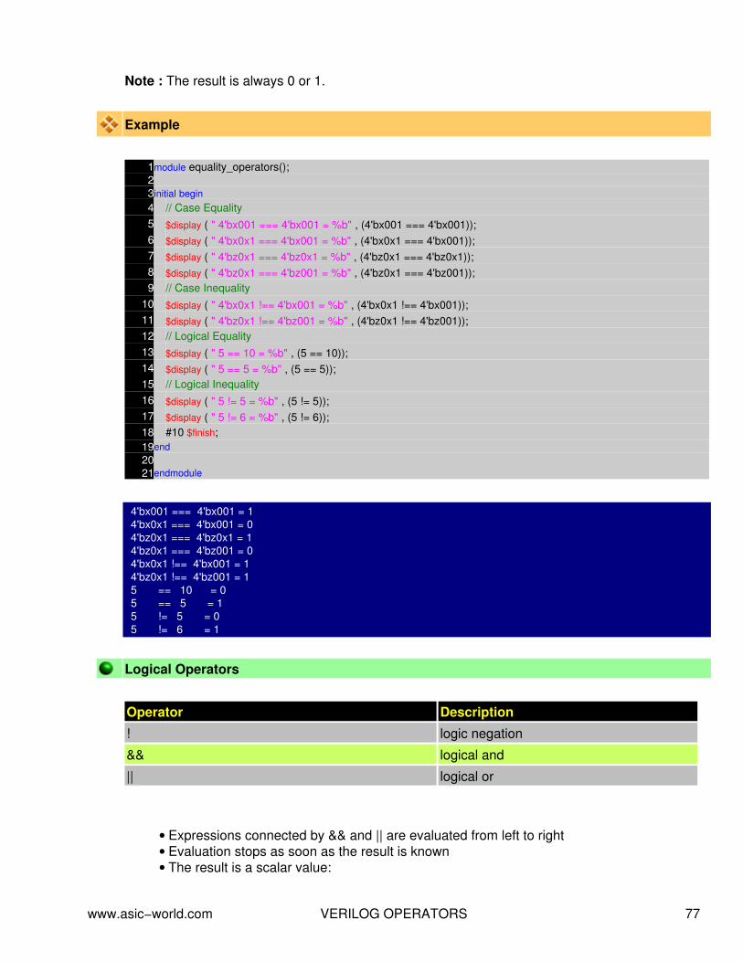
Note : The result is always 0 or 1.
Example
1module equality_operators();23initial begin4 // Case Equality5 $display ( " 4'bx001 === 4'bx001 = %b" , (4'bx001 === 4'bx001));6 $display ( " 4'bx0x1 === 4'bx001 = %b" , (4'bx0x1 === 4'bx001));7 $display ( " 4'bz0x1 === 4'bz0x1 = %b" , (4'bz0x1 === 4'bz0x1));8 $display ( " 4'bz0x1 === 4'bz001 = %b" , (4'bz0x1 === 4'bz001));9 // Case Inequality
10 $display ( " 4'bx0x1 !== 4'bx001 = %b" , (4'bx0x1 !== 4'bx001));11 $display ( " 4'bz0x1 !== 4'bz001 = %b" , (4'bz0x1 !== 4'bz001));12 // Logical Equality13 $display ( " 5 == 10 = %b" , (5 == 10));14 $display ( " 5 == 5 = %b" , (5 == 5));15 // Logical Inequality16 $display ( " 5 != 5 = %b" , (5 != 5));17 $display ( " 5 != 6 = %b" , (5 != 6));18 #10 $finish;19end2021endmodule
4'bx001 === 4'bx001 = 1 4'bx0x1 === 4'bx001 = 0 4'bz0x1 === 4'bz0x1 = 1 4'bz0x1 === 4'bz001 = 0 4'bx0x1 !== 4'bx001 = 1 4'bz0x1 !== 4'bz001 = 1 5 == 10 = 0 5 == 5 = 1 5 != 5 = 0 5 != 6 = 1
Logical Operators
Operator Description
! logic negation
&& logical and
|| logical or
Expressions connected by && and || are evaluated from left to right• Evaluation stops as soon as the result is known• The result is a scalar value:•
www.asic−world.com VERILOG OPERATORS 77

0 if the relation is false♦ 1 if the relation is true♦ x if any of the operands has unknown x bits♦
Example
1module logical_operators();23initial begin4 // Logical AND5 $display ( "1'b1 && 1'b1 = %b" , (1'b1 && 1'b1));6 $display ( "1'b1 && 1'b0 = %b" , (1'b1 && 1'b0));7 $display ( "1'b1 && 1'bx = %b" , (1'b1 && 1'bx));8 // Logical OR9 $display ( "1'b1 || 1'b0 = %b" , (1'b1 || 1'b0));
10 $display ( "1'b0 || 1'b0 = %b" , (1'b0 || 1'b0));11 $display ( "1'b0 || 1'bx = %b" , (1'b0 || 1'bx));12 // Logical Negation13 $display ( "! 1'b1 = %b" , (! 1'b1));14 $display ( "! 1'b0 = %b" , (! 1'b0));15 #10 $finish;16end1718endmodule
1'b1 && 1'b1 = 1 1'b1 && 1'b0 = 0 1'b1 && 1'bx = x 1'b1 || 1'b0 = 1 1'b0 || 1'b0 = 0 1'b0 || 1'bx = x ! 1'b1 = 0 ! 1'b0 = 1
Bit−wise OperatorsBitwise operators perform a bit wise operation on two operands. They take each bit in one operandand perform the operation with the corresponding bit in the other operand. If one operand isshorter than the other, it will be extended on left side with zeros to match the length of the longeroperand.
Operator Description
~ negation
& and
| inclusive or
^ exclusive or
^~ or ~^ exclusive nor (equivalence)
www.asic−world.com VERILOG OPERATORS 78
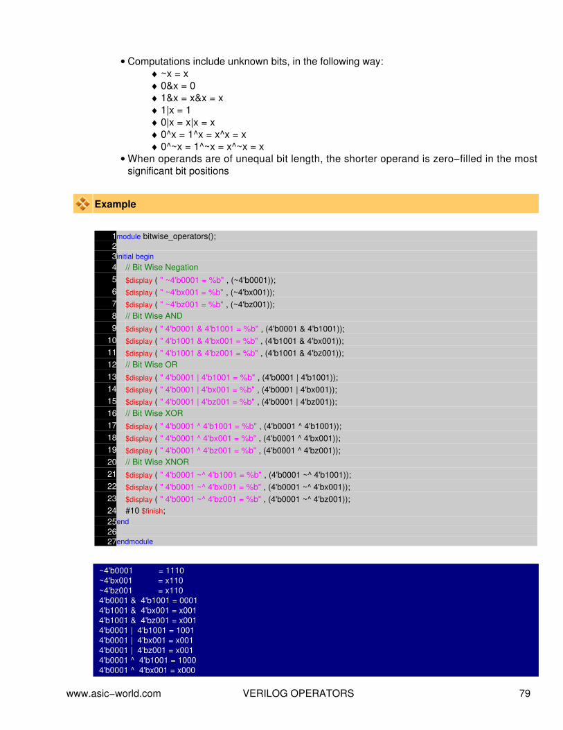
Computations include unknown bits, in the following way:• ~x = x♦ 0&x = 0♦ 1&x = x&x = x♦ 1|x = 1♦ 0|x = x|x = x♦ 0^x = 1^x = x^x = x♦ 0^~x = 1^~x = x^~x = x♦
When operands are of unequal bit length, the shorter operand is zero−filled in the mostsignificant bit positions
•
Example
1module bitwise_operators();23initial begin4 // Bit Wise Negation5 $display ( " ~4'b0001 = %b" , (~4'b0001));6 $display ( " ~4'bx001 = %b" , (~4'bx001));7 $display ( " ~4'bz001 = %b" , (~4'bz001));8 // Bit Wise AND9 $display ( " 4'b0001 & 4'b1001 = %b" , (4'b0001 & 4'b1001));
10 $display ( " 4'b1001 & 4'bx001 = %b" , (4'b1001 & 4'bx001));11 $display ( " 4'b1001 & 4'bz001 = %b" , (4'b1001 & 4'bz001));12 // Bit Wise OR13 $display ( " 4'b0001 | 4'b1001 = %b" , (4'b0001 | 4'b1001));14 $display ( " 4'b0001 | 4'bx001 = %b" , (4'b0001 | 4'bx001));15 $display ( " 4'b0001 | 4'bz001 = %b" , (4'b0001 | 4'bz001));16 // Bit Wise XOR17 $display ( " 4'b0001 ^ 4'b1001 = %b" , (4'b0001 ^ 4'b1001));18 $display ( " 4'b0001 ^ 4'bx001 = %b" , (4'b0001 ^ 4'bx001));19 $display ( " 4'b0001 ^ 4'bz001 = %b" , (4'b0001 ^ 4'bz001));20 // Bit Wise XNOR21 $display ( " 4'b0001 ~^ 4'b1001 = %b" , (4'b0001 ~^ 4'b1001));22 $display ( " 4'b0001 ~^ 4'bx001 = %b" , (4'b0001 ~^ 4'bx001));23 $display ( " 4'b0001 ~^ 4'bz001 = %b" , (4'b0001 ~^ 4'bz001));24 #10 $finish;25end2627endmodule
~4'b0001 = 1110 ~4'bx001 = x110 ~4'bz001 = x110 4'b0001 & 4'b1001 = 0001 4'b1001 & 4'bx001 = x001 4'b1001 & 4'bz001 = x001 4'b0001 | 4'b1001 = 1001 4'b0001 | 4'bx001 = x001 4'b0001 | 4'bz001 = x001 4'b0001 ^ 4'b1001 = 1000 4'b0001 ^ 4'bx001 = x000
www.asic−world.com VERILOG OPERATORS 79

4'b0001 ^ 4'bz001 = z000 4'b0001 ~^ 4'b1001 = 0111 4'b0001 ~^ 4'bx001 = x111 4'b0001 ~^ 4'bz001 = x111
Reduction Operators
Operator Description
& and
~& nand
| or
~| nor
^ xor
^~ or ~^ xnor
Reduction operators are unary.• They perform a bit−wise operation on a single operand to produce a single bit result.• Reduction unary NAND and NOR operators operate as AND and OR respectively, but withtheir outputs negated.
•
Unknown bits are treated as described before.♦
Example
1module reduction_operators();23initial begin4 // Bit Wise AND reduction5 $display ( " & 4'b1001 = %b" , (& 4'b1001));6 $display ( " & 4'bx111 = %b" , (& 4'bx111));7 $display ( " & 4'bz111 = %b" , (& 4'bz111));8 // Bit Wise NAND reduction9 $display ( " ~& 4'b1001 = %b" , (~& 4'b1001));
10 $display ( " ~& 4'bx001 = %b" , (~& 4'bx001));11 $display ( " ~& 4'bz001 = %b" , (~& 4'bz001));12 // Bit Wise OR reduction13 $display ( " | 4'b1001 = %b" , (| 4'b1001));14 $display ( " | 4'bx000 = %b" , (| 4'bx000));15 $display ( " | 4'bz000 = %b" , (| 4'bz000));16 // Bit Wise OR reduction17 $display ( " ~| 4'b1001 = %b" , (~| 4'b1001));18 $display ( " ~| 4'bx001 = %b" , (~| 4'bx001));19 $display ( " ~| 4'bz001 = %b" , (~| 4'bz001));20 // Bit Wise XOR reduction
www.asic−world.com VERILOG OPERATORS 80
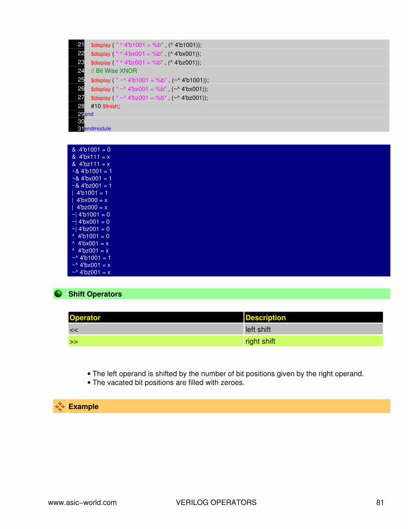
21 $display ( " ^ 4'b1001 = %b" , (^ 4'b1001));22 $display ( " ^ 4'bx001 = %b" , (^ 4'bx001));23 $display ( " ^ 4'bz001 = %b" , (^ 4'bz001));24 // Bit Wise XNOR25 $display ( " ~^ 4'b1001 = %b" , (~^ 4'b1001));26 $display ( " ~^ 4'bx001 = %b" , (~^ 4'bx001));27 $display ( " ~^ 4'bz001 = %b" , (~^ 4'bz001));28 #10 $finish;29end3031endmodule
& 4'b1001 = 0 & 4'bx111 = x & 4'bz111 = x ~& 4'b1001 = 1 ~& 4'bx001 = 1 ~& 4'bz001 = 1 | 4'b1001 = 1 | 4'bx000 = x | 4'bz000 = x ~| 4'b1001 = 0 ~| 4'bx001 = 0 ~| 4'bz001 = 0 ^ 4'b1001 = 0 ^ 4'bx001 = x ^ 4'bz001 = x ~^ 4'b1001 = 1 ~^ 4'bx001 = x ~^ 4'bz001 = x
Shift Operators
Operator Description
<< left shift
>> right shift
The left operand is shifted by the number of bit positions given by the right operand.• The vacated bit positions are filled with zeroes.•
Example
www.asic−world.com VERILOG OPERATORS 81

1module shift_operators();23initial begin4 // Left Shift5 $display ( " 4'b1001 << 1 = %b" , (4'b1001 << 1));6 $display ( " 4'b10x1 << 1 = %b" , (4'b10x1 << 1));7 $display ( " 4'b10z1 << 1 = %b" , (4'b10z1 << 1));8 // Right Shift9 $display ( " 4'b1001 >> 1 = %b" , (4'b1001 >> 1));
10 $display ( " 4'b10x1 >> 1 = %b" , (4'b10x1 >> 1));11 $display ( " 4'b10z1 >> 1 = %b" , (4'b10z1 >> 1));12 #10 $finish;13end1415endmodule
4'b1001 <<1 = 0010 4'b10x1 <<1 = 0x10 4'b10z1 <<1 = 0z10 4'b1001 >> 1 = 0100 4'b10x1 >> 1 = 010x 4'b10z1 >> 1 = 010z
Concatenation Operators
Concatenations are expressed using the brace characters { and }, with commas separatingthe expressions within
•
Example: + {a, b[3:0], c, 4'b1001} // if a and c are 8−bit numbers, the results has 24bits
♦
Unsized constant numbers are not allowed in concatenations•
Example
1module concatenation_operator();23initial begin4 // concatenation5 $display ( " {4'b1001,4'b10x1} = %b" , {4'b1001,4'b10x1});6 #10 $finish;7end89endmodule
{4'b1001,4'b10x1} = 100110x1
Replication Operator OperatorsReplication operator is used for replication group of bits n times. Say you have 4 bit variable andyou want to replicate it 4 times to get a 16 bit variable, then we can use replication operator.
www.asic−world.com VERILOG OPERATORS 82

Operator Description
{n{m}} Replicate value m, n times
Repetition multipliers that must be constants can be used:• {3{a}} // this is equivalent to {a, a, a}♦
Nested concatenations and replication operator are possible:• {b, {3{c, d}}} // this is equivalent to {b, c, d, c, d, c, d}♦
Example
1module replication_operator();23initial begin4 // replication5 $display ( " {4{4'b1001} = %b" , {4{4'b1001}});6 // replication and concatenation7 $display ( " {4{4'b1001,1'bz} = %b" , {4{4'b1001,1'bz}});8 #10 $finish;9end
1011endmodule
{4{4'b1001} = 1001100110011001 {4{4'b1001,1'bz} = 1001z1001z1001z1001z
Conditional Operators
The conditional operator has the following C−like format:• cond_expr ? true_expr : false_expr♦
The true_expr or the false_expr is evaluated and used as a result depending on ifcond_expr evaluates to true or false
•
Example
1module conditional_operator();23wire out;4reg enable,data;5// Tri state buffer6assign out = (enable) ? data : 1'bz;78initial begin9 $display ( "time\t enable data out" );
10 $monitor ( "%g\t %b %b %b" ,$time,enable,data,out);
www.asic−world.com VERILOG OPERATORS 83

11 enable = 0;12 data = 0;13 #1 data = 1;14 #1 data = 0;15 #1 enable = 1;16 #1 data = 1;17 #1 data = 0;18 #1 enable = 0;19 #10 $finish;20end2122endmodule
time enable data out 0 0 0 z 1 0 1 z 2 0 0 z 3 1 0 0 4 1 1 1 5 1 0 0 6 0 0 z
Operator Precedence
Operator Symbols
Unary, Multiply, Divide, Modulus !, ~, *, /, %
Add, Subtract, Shift +, − , <>
Relation, Equality ,<=,>=,==,!=,===,!===
Reduction &, !&,^,^~,|,~|
Logic &&, ||
Conditional ?
www.asic−world.com VERILOG OPERATORS 84

NOTES−−
−−
−−
−−
−−
−−
−−
−−
−−
−−
−−
−−
−−
−−
−−
−−
−−
−−
−−
−−
−−
−−
−−
−−
−−
−−
−−
−−
−−
−−
−−
−−
−−
−−
−−
−−
−−
−−
www.asic−world.com VERILOG OPERATORS 85

VERILOG BEHAVIORAL MODELINGCHAPTER 9
www.asic−world.com VERILOG BEHAVIORAL MODELING 86

Verilog HDL Abstraction Levels
Behavioral Models : Higher level of modeling where behavior of logic is modeled.• RTL Models : Logic is modeled at register level• Structural Models : Logic is modeled at both register level and gate level.•
Procedural BlocksVerilog behavioral code is inside procedures blocks, but there is a exception, some behavioralcode also exist outside procedures blocks. We can see this in detail as we make progress.
There are two types of procedural blocks in Verilog
initial : initial blocks execute only once at time zero (start execution at time zero).• always : always blocks loop to execute over and over again, in other words as namemeans, it executes always.
•
Example − initial
1module initial_example();2reg clk,reset,enable,data;34initial begin5 clk = 0;6 reset = 0;7 enable = 0;8 data = 0;9end
1011endmodule
In the above example, the initial block execution and always block execution starts at time 0.Always blocks waits for the the event, here positive edge of clock, where as initial block withoutwaiting just executed all the statements within begin and end statement.
Example − always
www.asic−world.com VERILOG BEHAVIORAL MODELING 87

1module always_example();2reg clk,reset,enable,q_in,data;34always @ (posedge clk)5if (reset) begin6 data <= 0;7end else if (enable) begin8 data <= q_in;9end
1011endmodule
In always block, when the trigger event occurs, the code inside begin and end is executed and theonce again the always block waits for next posedge of clock. This process of waiting and executingon event is repeated till simulation stops.
Procedural Assignment Statements
Procedural assignment statements assign values to reg , integer , real , or time variablesand can not assign values to nets ( wire data types)
•
You can assign to the register (reg data type) the value of a net (wire), constant, anotherregister, or a specific value.
•
Example − Bad procedural assignment
1module initial_bad();2reg clk,reset;3wire enable,data;45initial begin6 clk = 0;7 reset = 0;8 enable = 0;9 data = 0;
10end1112endmodule
Example − Good procedural assignment
1module initial_good();2reg clk,reset,enable,data;34initial begin5 clk = 0;6 reset = 0;7 enable = 0;8 data = 0;9end
www.asic−world.com VERILOG BEHAVIORAL MODELING 88

1011endmodule
Procedural Assignment Groups
If a procedure block contains more then one statement, those statements must be enclosed within
Sequential begin − end block• Parallel fork − join block•
When using begin−end, we can give name to that group. This is called named blocks.
Example − "begin−end"
1module initial_begin_end();2reg clk,reset,enable,data;34initial begin5 #1 clk = 0;6 #10 reset = 0;7 #5 enable = 0;8 #3 data = 0;9end
1011endmodule
Begin : clk gets 0 after 1 time unit, reset gets 0 after 11 time units, enable after 16 time units, dataafter 19 units. All the statements are executed in sequentially.
Example − "fork−join"
1module initial_fork_join();2reg clk,reset,enable,data;34initial fork5 #1 clk = 0;6 #10 reset = 0;7 #5 enable = 0;8 #3 data = 0;9join
1011endmodule
Fork : clk gets value after 1 time unit, reset after 10 time units, enable after 5 time units, data after3 time units. All the statements are executed in parallel.
Sequential Statement Groups
www.asic−world.com VERILOG BEHAVIORAL MODELING 89
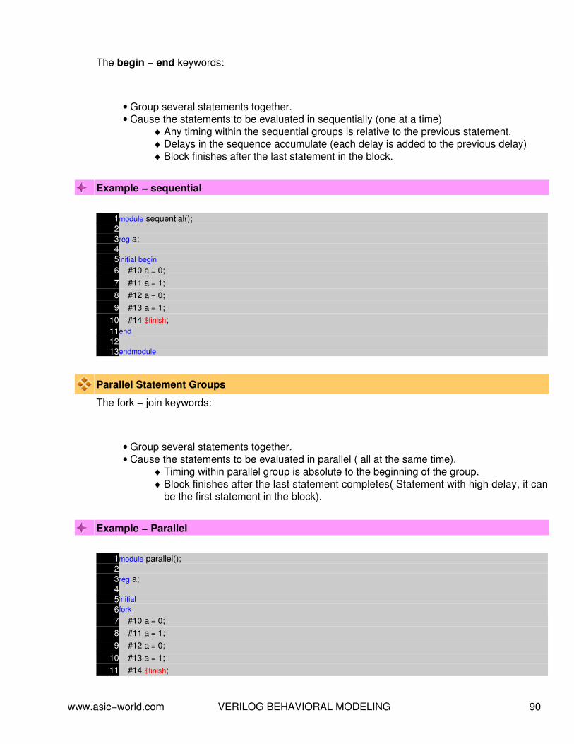
The begin − end keywords:
Group several statements together.• Cause the statements to be evaluated in sequentially (one at a time)•
Any timing within the sequential groups is relative to the previous statement.♦ Delays in the sequence accumulate (each delay is added to the previous delay)♦ Block finishes after the last statement in the block.♦
Example − sequential
1module sequential();23reg a;45initial begin6 #10 a = 0;7 #11 a = 1;8 #12 a = 0;9 #13 a = 1;
10 #14 $finish;11end1213endmodule
Parallel Statement Groups
The fork − join keywords:
Group several statements together.• Cause the statements to be evaluated in parallel ( all at the same time).•
Timing within parallel group is absolute to the beginning of the group.♦ Block finishes after the last statement completes( Statement with high delay, it canbe the first statement in the block).
♦
Example − Parallel
1module parallel();23reg a;45initial6fork
7 #10 a = 0;8 #11 a = 1;9 #12 a = 0;
10 #13 a = 1;11 #14 $finish;
www.asic−world.com VERILOG BEHAVIORAL MODELING 90

12join1314endmodule
Example − Mixing "begin−end" and "fork − join"
1module fork_join();23reg clk,reset,enable,data;45initial begin6 $display ( "Starting simulation" );7 fork : FORK_VAL8 #1 clk = 0;9 #5 reset = 0;
10 #5 enable = 0;11 #2 data = 0;12 join
13 $display ( "Terminating simulation" );14 #10 $finish;15end1617endmodule
Blocking and Nonblocking assignment
Blocking assignments are executed in the order they are coded, Hence they are sequential. Sincethey block the execution of next statment, till the current statement is excuted, they are calledblocking assignments. Assignment are made with "=" symbol. Example a = b;
Nonblocking assignements are executed in parallel. Since the execution of next statement is notblocked due to execution of current statement, they are called nonblocking statement.Assignement are made with "<=" symbol. Example a <= b;
Note : Correct way to spell nonblocking is nonblocking and not non−blocking.
Example − blocking and nonblocking
1module blocking_nonblocking();23reg a,b,c,d;4// Blocking Assignment5initial begin6 #10 a = 0;7 #11 a = 1;8 #12 a = 0;9 #13 a = 1;
10end1112initial begin
www.asic−world.com VERILOG BEHAVIORAL MODELING 91

13 #10 b <= 0;14 #11 b <= 1;15 #12 b <= 0;16 #13 b <= 1;17end1819initial begin20 c = #10 0;21 c = #11 1;22 c = #12 0;23 c = #13 1;24end2526initial begin27 d <= #10 0;28 d <= #11 1;29 d <= #12 0;30 d <= #13 1;31end3233initial begin34 $monitor( " TIME = %t A = %b B = %b C = %b D = %b" ,$time,a,b,c,d);35 #50 $finish(1);36end3738endmodule
Waveform
The Conditional Statement if−elseThe if − else statement controls the execution of other statements, In programming language likec, if − else controls the flow of program. When more then one statement needs to be executed fora if conditions, then we need to use begin and end as seen in earlier examples.
Syntax : ifif (condition)statements;
www.asic−world.com VERILOG BEHAVIORAL MODELING 92
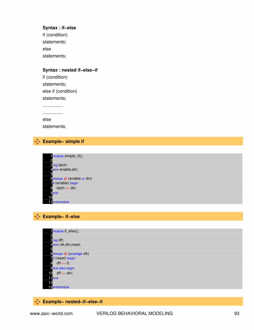
Syntax : if−elseif (condition)statements;elsestatements;
Syntax : nested if−else−ifif (condition)statements;else if (condition)statements;................................elsestatements;
Example− simple if
1module simple_if();23reg latch;4wire enable,din;56always @ (enable or din)7if (enable) begin8 latch <= din;9end
1011endmodule
Example− if−else
1module if_else();23reg dff;4wire clk,din,reset;56always @ (posedge clk)7if (reset) begin8 dff <= 0;9end else begin
10 dff <= din;11end1213endmodule
Example− nested−if−else−if
www.asic−world.com VERILOG BEHAVIORAL MODELING 93

1module nested_if();23reg [3:0] counter;4wire clk,reset,enable, up_en, down_en;56always @ (posedge clk)7// If reset is asserted8if (reset == 1'b0) begin9 counter <= 4'b0000;
10 // If counter is enable and up count is mode11end else if (enable == 1'b1 && up_en == 1'b1) begin12 counter <= counter + 1'b1;13 // If counter is enable and down count is mode14end else if (enable == 1'b1 && down_en == 1'b1) begin15 counter <= counter − 1'b0;16 // If counting is disabled17end else begin18 counter <= counter; // Redundant code19end2021endmodule
Parallel if−else
In the above example, the (enable == 1'b1 && up_en == 1'b1) is given highest pritority andcondition (enable == 1'b1 && down_en == 1'b1) is given lowest priority. We normally don't includereset checking in priority as this does not falls in the combo logic input to the flip−flop as shown infigure below.
So when we need priority logic, we use nexted if−else statments. On other end if we don't want toimplement priority logic, knowing that only one input is active at a time i.e. all inputs are mutuallyexclusive, then we can write the code as shown below.
Its known fact that priority implementation takes more logic to implement then parallelimplementation. So if you know the inputs are mutually exclusive, then you can code the logic inparallel if.
www.asic−world.com VERILOG BEHAVIORAL MODELING 94
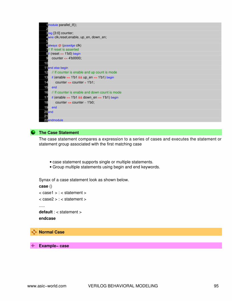
1module parallel_if();23reg [3:0] counter;4wire clk,reset,enable, up_en, down_en;56always @ (posedge clk)7// If reset is asserted8if (reset == 1'b0) begin9 counter <= 4'b0000;
1011end else begin12 // If counter is enable and up count is mode13 if (enable == 1'b1 && up_en == 1'b1) begin
14 counter <= counter + 1'b1;15 end
16 // If counter is enable and down count is mode17 if (enable == 1'b1 && down_en == 1'b1) begin
18 counter <= counter − 1'b0;19 end
20end2122endmodule
The Case StatementThe case statement compares a expression to a series of cases and executes the statement orstatement group associated with the first matching case
case statement supports single or multiple statements.• Group multiple statements using begin and end keywords.•
Synax of a case statement look as shown below.case ()< case1 > : < statement >< case2 > : < statement >.....default : < statement >endcase
Normal Case
Example− case
www.asic−world.com VERILOG BEHAVIORAL MODELING 95

1module mux (a,b,c,d,sel,y);2input a, b, c, d;3input [1:0] sel;4output y;56reg y;78always @ (a or b or c or d or sel)9case (sel)
10 0 : y = a;11 1 : y = b;12 2 : y = c;13 3 : y = d;14 default : $display( "Error in SEL" );15endcase1617endmodule
Example− case without default
1module mux_without_default (a,b,c,d,sel,y);2input a, b, c, d;3input [1:0] sel;4output y;56reg y;78always @ (a or b or c or d or sel)9case (sel)
10 0 : y = a;11 1 : y = b;12 2 : y = c;13 3 : y = d;14 2'bxx,2'bx0,2'bx1,2'b0x,2'b1x,15 2'bzz,2'bz0,2'bz1,2'b0z,2'b1z : $display( "Error in SEL" );16endcase1718endmodule
Above example shows how to specifiy multiple case items as single case item.
The Verilog case statement does an identity comparison (like the === operator), One can use thecase statement to check for logic x and z values as shown in below example.
Example− case with x and z
www.asic−world.com VERILOG BEHAVIORAL MODELING 96

1module case_xz(enable);2input enable;34always @ (enable)5case(enable)6 1'bz : $display ( "enable is floating" );7 1'bx : $display ( "enable is unknown" );8 default : $display ( "enable is %b" ,enable);9endcase
1011endmodule
The casez and casex statement
Special versions of the case statement allow the x ad z logic values to be used as "don't care"
casez : Treates z as the don't care.• casex : Treates x and z as don't care.•
Example− casez
1module casez_example(opcode,a,b,c,out);2input [3:0] opcode;3input [1:0] a,b,c;4output[1:0] out;5reg [1:0] out;67always @ (opcode or a or b or c)8casez(opcode)9 // Bit 0 is matched with "x"
10 4'b1zzx : out = a; // Don't care about lower 3:1 bits11 4'b01?? : out = b; // The ? is same as z in a number12 4'b001? : out = c;13 default : $display ( "Error xxxx does matches 0000" );14endcase1516endmodule
Example− casex
1module casex_example(opcode,a,b,c,out);2input [3:0] opcode;3input [1:0] a,b,c;4output[1:0] out;5reg [1:0] out;67always @ (opcode or a or b or c)8casex(opcode)9 4'b1zzx : out = a; // Don't care 3:0 bits
10 4'b01?? : out = b; // The ? is same as z in a number11 4'b001? : out = c;
www.asic−world.com VERILOG BEHAVIORAL MODELING 97

12 default : $display ( "Error xxxx does matches 0000" );13endcase1415endmodule
Example− Comparing case, casex, casez
1module case_compare(sel);23input sel;45always @ (sel)6case (sel)7 1'b0 : $display( "Normal : Logic 0 on sel" );8 1'b1 : $display( "Normal : Logic 1 on sel" );9 1'bx : $display( "Normal : Logic x on sel" );
10 1'bz : $display( "Normal : Logic z on sel" );11endcase1213always @ (sel)14casex (sel)15 1'b0 : $display( "CASEX : Logic 0 on sel" );16 1'b1 : $display( "CASEX : Logic 1 on sel" );17 1'bx : $display( "CASEX : Logic x on sel" );18 1'bz : $display( "CASEX : Logic z on sel" );19endcase2021always @ (sel)22casez (sel)23 1'b0 : $display( "CASEZ : Logic 0 on sel" );24 1'b1 : $display( "CASEZ : Logic 1 on sel" );25 1'bx : $display( "CASEZ : Logic x on sel" );26 1'bz : $display( "CASEZ : Logic z on sel" );27endcase2829endmodule
Looping StatementsLooping statements appear inside a procedural blocks only, Verilog has four looping statementslike any other programming language.
forever• repeat• while• for•
The forever statement
www.asic−world.com VERILOG BEHAVIORAL MODELING 98

The forever loop executes continually, the loop never ends. Normally we use forever statement ininitial blocks.
syntax : forever < statement >
Once should be very careful in using a forever statement, if no timing construct is present in theforever statement, simulation could hang. Below code is one such application, where timingconstruct is included inside a forever statement.
Example − Free running clock generator
1module forever_example ();23reg clk;45initial begin6 #1 clk = 0;7 forever begin
8 #5 clk = !clk;9 end
10end1112initial begin13 $monitor ( "Time = %d clk = %b" ,$time, clk);14 #100 $finish;15end1617endmodule
The repeat statement
The repeat loop executes statement fixed < number > of times.
syntax : repeat (< number >) < statement >
Example− repeat
1module repeat_example();2reg [3:0] opcode;3reg [15:0] data;4reg temp;56always @ (opcode or data)7begin
8 if (opcode == 10) begin
9 // Perform rotate10 repeat (8) begin
11 #1 temp = data[15];12 data = data << 1;13 data[0] = temp;
www.asic−world.com VERILOG BEHAVIORAL MODELING 99

14 end
15 end
16end17// Simple test code18initial begin19 $display ( " TEMP DATA" );20 $monitor ( " %b %b " ,temp, data);21 #1 data = 18'hF0;22 #1 opcode = 10;23 #10 opcode = 0;24 #1 $finish;25end2627endmodule
The while loop statement
The while loop executes as long as an evaluates as true. This is same as in any otherprogramming language.
syntax : while ()
Example− while
1module while_example();23reg [5:0] loc;4reg [7:0] data;56always @ (data or loc)7begin
8 loc = 0;9 // If Data is 0, then loc is 32 (invalid value)
10 if (data == 0) begin
11 loc = 32;12 end else begin
13 while (data[0] == 0) begin
14 loc = loc + 1;15 data = data >> 1;16 end
17 end
18 $display ( "DATA = %b LOCATION = %d" ,data,loc);19end2021initial begin22 #1 data = 8'b11;23 #1 data = 8'b100;24 #1 data = 8'b1000;25 #1 data = 8'b1000_0000;26 #1 data = 8'b0;
www.asic−world.com VERILOG BEHAVIORAL MODELING 100
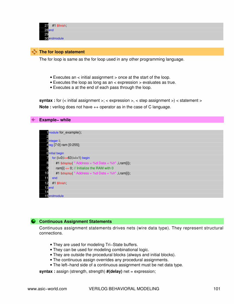
27 #1 $finish;28end2930endmodule
The for loop statement
The for loop is same as the for loop used in any other programming language.
Executes an < initial assignment > once at the start of the loop.• Executes the loop as long as an < expression > evaluates as true.• Executes a at the end of each pass through the loop.•
syntax : for (< initial assignment >; < expression >, < step assignment >) < statement >Note : verilog does not have ++ operator as in the case of C language.
Example− while
1module for_example();23integer i;4reg [7:0] ram [0:255];56initial begin7 for (i=0;i<=63;i=i+1) begin
8 #1 $display( " Address = %d Data = %h" ,i,ram[i]);9 ram[i] <= 0; // Initialize the RAM with 0
10 #1 $display( " Address = %d Data = %h" ,i,ram[i]);11 end
12 #1 $finish;13end1415endmodule
Continuous Assignment StatementsContinuous assignment statements drives nets (wire data type). They represent structuralconnections.
They are used for modeling Tri−State buffers.• They can be used for modeling combinational logic.• They are outside the procedural blocks (always and initial blocks).• The continuous assign overrides any procedural assignments.• The left−hand side of a continuous assignment must be net data type.•
syntax : assign (strength, strength) #(delay) net = expression;
www.asic−world.com VERILOG BEHAVIORAL MODELING 101

Example − One bit Adder
1module adder_using_assign ();2reg a, b;3wire sum, carry;45assign #5 {carry,sum} = a+b;67initial begin8 $monitor ( " A = %b B = %b CARRY = %b SUM = %b" ,a,b,carry,sum);9 #10 a = 0;
10 b = 0;11 #10 a = 1;12 #10 b = 1;13 #10 a = 0;14 #10 b = 0;15 #10 $finish;16end1718endmodule
Example − Tri−state buffer
1module tri_buf_using_assign();2reg data_in, enable;3wire pad;45assign pad = (enable) ? data_in : 1'bz;67initial begin8 $monitor ( "ENABLE = %b DATA : %b PAD %b" ,enable, data_in,pad);9 #1 enable = 0;
10 #1 data_in = 1;11 #1 enable = 1;12 #1 data_in = 0;13 #1 enable = 0;14 #1 $finish;15end1617endmodule
Propagation DelayContinuous Assignments may have a delay specified, Only one delay for all transitions may bespecified. A minimum:typical:maximum delay range may be specified.
Example − Tri−state buffer
www.asic−world.com VERILOG BEHAVIORAL MODELING 102

1module tri_buf_using_assign_delays();2reg data_in, enable;3wire pad;45assign #(1:2:3) pad = (enable) ? data_in : 1'bz;67initial begin8 $monitor ( "ENABLE = %b DATA : %b PAD %b" ,enable, data_in,pad);9 #10 enable = 0;
10 #10 data_in = 1;11 #10 enable = 1;12 #10 data_in = 0;13 #10 enable = 0;14 #10 $finish;15end1617endmodule
Procedural Block ControlProcedural blocks become active at simulation time zero, Use level sensitive even controls tocontrol the execution of a procedure.
1module dlatch_using_always();2reg q;34reg d, enable;56always @ (d or enable)7if (enable) begin8 q = d;9end
1011initial begin12 $monitor ( " ENABLE = %b D = %b Q = %b" ,enable,d,q);13 #1 enable = 0;14 #1 d = 1;15 #1 enable = 1;16 #1 d = 0;17 #1 d = 1;18 #1 d = 0;19 #1 enable = 0;20 #10 $finish;21end2223endmodule
An event sensitive delay at the begining of a procedure, any change in either d or enable satisfiesthe even control and allows the execution of the statements in the procedure. The procedure issensitive to any change in d or enable.
www.asic−world.com VERILOG BEHAVIORAL MODELING 103

Combo Logic using Procedural Coding
To model combinational logic, a procedure block must be sensitive to any change on the input.There is one important rule that needs to be followed while modelling combinational logic. If youuse conditional checking using "if", then you need to mention the "else" part. Missing the else partresults in latch. If you don't like typing the else part, then you must initilize all the variables of thatcombo block to zero as soon as it enters.
Example − One bit Adder
1module adder_using_always ();2reg a, b;3reg sum, carry;45always @ (a or b)6begin
7 {carry,sum} = a + b;8end9
10initial begin11 $monitor ( " A = %b B = %b CARRY = %b SUM = %b" ,a,b,carry,sum);12 #10 a = 0;13 b = 0;14 #10 a = 1;15 #10 b = 1;16 #10 a = 0;17 #10 b = 0;18 #10 $finish;19end2021endmodule
The statements within the procedural block work with entire vectors at a time.
Example − 4−bit Adder
1module adder_4_bit_using_always ();2reg[3:0] a, b;3reg [3:0] sum;4reg carry;56always @ (a or b)7begin
8 {carry,sum} = a + b;9end
1011initial begin12 $monitor ( " A = %b B = %b CARRY = %b SUM = %b" ,a,b,carry,sum);13 #10 a = 8;14 b = 7;15 #10 a = 10;16 #10 b = 15;
www.asic−world.com VERILOG BEHAVIORAL MODELING 104

17 #10 a = 0;18 #10 b = 0;19 #10 $finish;20end2122endmodule
Example − Ways to avoid Latches − Cover all conditions
1module avoid_latch_else ();23reg q;4reg enable, d;56always @ (enable or d)7if (enable) begin8 q = d;9end else begin
10 q = 0;11end1213initial begin14 $monitor ( " ENABLE = %b D = %b Q = %b" ,enable,d,q);15 #1 enable = 0;16 #1 d = 0;17 #1 enable = 1;18 #1 d = 1;19 #1 d = 0;20 #1 d = 1;21 #1 d = 0;22 #1 d = 1;23 #1 enable = 0;24 #1 $finish;25end2627endmodule
Example − Ways to avoid Latches − Init the variables to zero
1module avoid_latch_init ();23reg q;4reg enable, d;56always @ (enable or d)7begin
8 q = 0;9 if (enable) begin
10 q = d;11 end
12end1314initial begin
www.asic−world.com VERILOG BEHAVIORAL MODELING 105

15 $monitor ( " ENABLE = %b D = %b Q = %b" ,enable,d,q);16 #1 enable = 0;17 #1 d = 0;18 #1 enable = 1;19 #1 d = 1;20 #1 d = 0;21 #1 d = 1;22 #1 d = 0;23 #1 d = 1;24 #1 enable = 0;25 #1 $finish;26end2728endmodule
Sequential Logic using Procedural Coding
To model sequential logic, a procedure block must be sensitive to positive edge or negative edgeof clock. To model asychronous reset, procedure block must be sensitive to both clock and reset.All the assigments to sequential logic should be made throught nonblocking assignement.
Sometimes it tempting to have multiple edge triggering variables in the sensitive list, this is fine forsimulation. But for synthesis this does not make sense, as in real life, flip−flop can have only oneclock, one reset and one preset. ( i.e posedge clk or posedge reset or posedge preset)
One of the common mistake the new beginner makes is using clock as the enable input toflip−flop. This is fine for simulation, but for synthesis, this is not right.
Example − Bad coding − Using two clocks
1module wrong_seq();23reg q;4reg clk1, clk2, d1, d2;56always @ (posedge clk1 or posedge clk2)7if (clk1) begin8 q <= d1;9end else if (clk2) begin
10 q <= d2;11end1213initial begin14 $monitor ( "CLK1 = %b CLK2 = %b D1 = %b D2 %b Q = %b" , clk1, clk2, d1, d2, q);15 clk1 = 0;16 clk2 = 0;17 d1 = 0;18 d2 = 1;19 #10 $finish;20end21
www.asic−world.com VERILOG BEHAVIORAL MODELING 106

22always23#1 clk1 = ~clk1;2425always26#1.9 clk2 = ~clk2;2728endmodule
Example − D Flip−flop with async reset and async preset
1module dff_async_reset_async_preset();23reg clk,reset,preset,d;4reg q;56always @ (posedge clk or posedge reset or posedge preset)7if (reset) begin8 q <= 0;9end else if (preset) begin
10 q <= 1;11end else begin12 q <= d;13end1415// Testbench code here16initial begin17 $monitor( "CLK = %b RESET = %b PRESET = %b D = %b Q = %b" ,clk,reset,preset,d,q);18 clk = 0;19 #1 reset = 0;20 preset = 0;21 d = 0;22 #1 reset = 1;23 #2 reset = 0;24 #2 preset = 1;25 #2 preset = 0;26 repeat (4) begin
27 #2 d = ~d;28 end
29 #2 $finish;30end3132always33#1 clk = ~clk;3435endmodule
Example − D Flip−flop with sync reset and sync preset
www.asic−world.com VERILOG BEHAVIORAL MODELING 107

1module dff_sync_reset_sync_preset();23reg clk,reset,preset,d;4reg q;56always @ (posedge clk)7if (reset) begin8 q <= 0;9end else if (preset) begin
10 q <= 1;11end else begin12 q <= d;13end1415// Testbench code here16initial begin17 $monitor( "CLK = %b RESET = %b PRESET = %b D = %b Q = %b" ,clk,reset,preset,d,q);18 clk = 0;19 #1 reset = 0;20 preset = 0;21 d = 0;22 #1 reset = 1;23 #2 reset = 0;24 #2 preset = 1;25 #2 preset = 0;26 repeat (4) begin
27 #2 d = ~d;28 end
29 #2 $finish;30end3132always33#1 clk = ~clk;3435endmodule
A procedure can't trigger itself
One cannot trigger the block with the variable that block assigns value or drive's.
1module trigger_itself();23reg clk;45always @ (clk)6#5 clk = !clk;78// Testbench code here9initial begin
10 $monitor( "TIME = %d CLK = %b" ,$time,clk);11 clk = 0;12 #500 $display( "TIME = %d CLK = %b" ,$time,clk);13 $finish;14end15
www.asic−world.com VERILOG BEHAVIORAL MODELING 108

16endmodule
Procedural Block Concurrency
If we have multiple always blocks inside one module, then all the blocks ( i.e. all the always blocksand initial blocks) will start executing at time 0 and will continue to execute concurrently.Sometimes this is leads to race condition, if coding is not done proper.
1module multiple_blocks ();2reg a,b;3reg c,d;4reg clk,reset;5// Combo Logic6always @ ( c)7begin
8 a = c;9end
10// Seq Logic11always @ (posedge clk)12if (reset) begin13 b <= 0;14end else begin15 b <= a & d;16end1718// Testbench code here19initial begin20 $monitor( "TIME = %d CLK = %b C = %b D = %b A = %b B = %b" ,$time, clk,c,d,a,b);21 clk = 0;22 reset = 0;23 c = 0;24 d = 0;25 #2 reset = 1;26 #2 reset = 0;27 #2 c = 1;28 #2 d = 1;29 #2 c = 0;30 #5 $finish;31end32// Clock generator33always34#1 clk = ~clk;3536endmodule
Race condition
www.asic−world.com VERILOG BEHAVIORAL MODELING 109

1module race_condition();2reg b;34initial begin5 b = 0;6end78initial begin9 b = 1;
10end1112endmodule
In the above code it is difficult to say the value of b, as both the blocks are suppose to execute atsame time. In Verilog if care is not taken, race condition is something that occurs very often.
Named Blocks
Blocks can be named by adding : block_name after the keyword begin. named block can bedisabled using disable statement.
Example − Named Blocks
1// This code find the lowest bit set2module named_block_disable();34reg [31:0] bit_detect;5reg [5:0] bit_position;6integer i;78always @ (bit_detect)9begin : BIT_DETECT
10 for (i = 0; i < 32 ; i = i + 1) begin
11 // If bit is set, latch the bit position12 // Disable the execution of the block13 if (bit_detect[i] == 1) begin
14 bit_position = i;15 disable BIT_DETECT;16 end else begin
17 bit_position = 32;18 end
19 end
20end2122// Testbench code here23initial begin24 $monitor( " INPUT = %b MIN_POSITION = %d" , bit_detect, bit_position);25 #1 bit_detect = 32'h1000_1000;26 #1 bit_detect = 32'h1100_0000;27 #1 bit_detect = 32'h1000_1010;28 #10 $finish;29end
www.asic−world.com VERILOG BEHAVIORAL MODELING 110

3031endmodule
In above example, BIT_DETECT is the named block and it is disabled when ever the bit position isdetected.
www.asic−world.com VERILOG BEHAVIORAL MODELING 111

NOTES−−
−−
−−
−−
−−
−−
−−
−−
−−
−−
−−
−−
−−
−−
−−
−−
−−
−−
−−
−−
−−
−−
−−
−−
−−
−−
−−
−−
−−
−−
−−
−−
−−
−−
−−
−−
−−
−−
www.asic−world.com VERILOG BEHAVIORAL MODELING 112
PROCEDURAL TIMING CONTROLCHAPTER 10
www.asic−world.com PROCEDURAL TIMING CONTROL 113

Procedural blocks and timing controls.
Delays controls.• Edge−Sensitive Event controls• Level−Sensitive Event controls−Wait statements• Named Events•
Delay Controls
Delays the execution of a procedural statement by specific simulation time.#< time > < statement >;
Example − clk_gen
1module clk_gen ();23reg clk, reset;45initial begin6 $monitor ( " RESET = %b CLOCK = %b" ,reset,clk);7 clk = 0;8 reset = 0;9 #2 reset = 1;
10 #5 reset = 0;11 #10 $finish;12end1314always15#1 clk = !clk;1617endmodule
Waveform
Edge sensitive Event Controls
Delays execution of the next statement until the specified transition on a signal.
syntax : @ (< posedge >|< negedge > signal) < statement >;
www.asic−world.com PROCEDURAL TIMING CONTROL 114

Example − Edge Wait
1module edge_wait_example();23reg enable, clk, trigger;45always @ (posedge enable)6begin
7 trigger = 0;8 // Wait for 5 clock cycles9 repeat (5) begin
10 @ (posedge clk) ;11 end
12 trigger = 1;13end1415//Testbench code here16initial begin17 $monitor ( "TIME : %d CLK : %b ENABLE : %b TRIGGER : %b" ,$time, clk,enable,trigger);18 clk = 0;19 enable = 0;20 #5 enable = 1;21 #1 enable = 0;22 #10 enable = 1;23 #1 enable = 0;24 #10 $finish;25end2627always28#1 clk = ~clk;2930endmodule
Waveform
www.asic−world.com PROCEDURAL TIMING CONTROL 115

Level−Sensitive Even Controls ( Wait statements )
Delays execution of the next statement until the evaluates as truesyntax : wait () ;
Example − Level Wait
1module wait_example();23reg mem_read, data_ready;4reg [7:0] data_bus, data;56always @ (mem_read or data_bus or data_ready)7begin
8 data = 0;9 while (mem_read == 1'b1) begin
10 // #1 is very important to avoid infinite loop11 wait (data_ready == 1) #1 data = data_bus;12 end
13end1415// Testbench Code here16initial begin17 $monitor ( "%d READ = %b READY = %b DATA = %b" , $time, mem_read, data_ready, data);18 data_bus = 0;19 mem_read = 0;20 data_ready = 0;21 #10 data_bus = 8'hDE;22 #10 mem_read = 1;23 #20 data_ready = 1;24 #1 mem_read = 1;25 #1 data_ready = 0;26 #10 data_bus = 8'hAD;27 #10 mem_read = 1;28 #20 data_ready = 1;29 #1 mem_read = 1;30 #1 data_ready = 0;31 #10 $finish;32end3334endmodule
Intra−Assignment Timing Controls
Intra−assignment controls evaluate the right side expression right always and assigns the resultafter the delay or event control.
In non−intra−assignment controls (delay or event control on the left side) right side expressionevaluated after delay or event control.
Example − Intra−Assignment
www.asic−world.com PROCEDURAL TIMING CONTROL 116

1module intra_assign();23reg a, b;45initial begin6 $monitor( "TIME = %d A = %b B = %b" ,$time, a , b);7 a = 1;8 b = 0;9 a = #10 0;
10 b = a;11 #20 $display( "TIME = %d A = %b B = %b" ,$time, a , b);12 $finish;13end1415endmodule
Waveform
Modeling Combo Logic with Continuous Assignments
Whenever any signal changes on the right hand side, the entire right−hand side is re−evaluatedand the result is assigned to the left hand side
Example − Tri−state Buffer
1module tri_buf_using_assign();2reg data_in, enable;3wire pad;45assign pad = (enable) ? data_in : 1'bz;67initial begin8 $monitor ( "ENABLE = %b DATA : %b PAD %b" ,enable, data_in,pad);9 #1 enable = 0;
10 #1 data_in = 1;11 #1 enable = 1;12 #1 data_in = 0;13 #1 enable = 0;14 #1 $finish;15end1617endmodule
www.asic−world.com PROCEDURAL TIMING CONTROL 117

Waveform
Example − Mux
1module mux_using_assign();2reg data_in_0, data_in_1;3wire data_out;4reg sel;56assign data_out = (sel) ? data_in_1 : data_in_0;78// Testbench code here9initial begin
10$monitor( "TIME = %d SEL = %b DATA0 = %b DATA1 = %b OUT = %b",$time,sel,data_in_0,data_in_1,data_out);
11 data_in_0 = 0;12 data_in_1 = 0;13 sel = 0;14 #10 sel = 1;15 #10 $finish;16end1718// Toggel data_in_0 at #119always20#1 data_in_0 = ~data_in_0;2122// Toggel data_in_1 at %1.523always24#1.3 data_in_1 = ~data_in_1;2526endmodule
Waveform
www.asic−world.com PROCEDURAL TIMING CONTROL 118

www.asic−world.com PROCEDURAL TIMING CONTROL 119

NOTES−−
−−
−−
−−
−−
−−
−−
−−
−−
−−
−−
−−
−−
−−
−−
−−
−−
−−
−−
−−
−−
−−
−−
−−
−−
−−
−−
−−
−−
−−
−−
−−
−−
−−
−−
−−
−−
−−
www.asic−world.com PROCEDURAL TIMING CONTROL 120

TASK AND FUNCTIONSCHAPTER 11
www.asic−world.com TASK AND FUNCTIONS 121

TaskTasks are used in all programming languages, generally known as Procedures or sub routines.Many lines of code are enclosed in task....end task brackets. Data is passed to the task, theprocessing done, and the result returned to a specified value. They have to be specifically called,with data in and outs, rather than just wired in to the general netlist. Included in the main body ofcode they can be called many times, reducing code repetition.
task are defined in the module in which they are used. it is possible to define task inseparate file and use compile directive 'include to include the task in the file whichinstantiates the task.
•
task can include timing delays, like posedge, negedge, # delay and wait.• task can have any number of inputs and outputs.• The variables declared within the task are local to that task. The order of declaration withinthe task defines how the variables passed to the task by the caller are used.
•
task can take, drive and source global variables, when no local variables are used. Whenlocal variables are used, it basically assigned output only at the end of task execution.
•
task can call another task or function.• task can be used for modeling both combinational and sequential logic.• A task must be specifically called with a statement, it cannot be used within an expressionas a function can.
•
Syntax
task begins with keyword task and end's with keyword endtask• input and output are declared after the keyword task.• local variables are declared after input and output declaration.•
Example − Simple Task
1module simple_task();23task convert;4input [7:0] temp_in;5output [7:0] temp_out;6begin
7 temp_out = (9/5) *( temp_in + 32)8end9endtask
1011endmodule
Example − Task using Global Variables
www.asic−world.com TASK AND FUNCTIONS 122

1module task_global();23reg [7:0] temp_out;4reg [7:0] temp_in;56task convert;7begin
8 temp_out = (9/5) *( temp_in + 32);9end
10endtask1112endmodule
Calling a Task
Lets assume that task in example 1 is stored in a file called mytask.v. Advantage of coding task inseparate file is that, it can be used in multiple module's.
1module task_calling (temp_a, temp_b, temp_c, temp_d);2input [7:0] temp_a, temp_c;3output [7:0] temp_b, temp_d;4reg [7:0] temp_b, temp_d;5`include "mytask.v"67always @ (temp_a)8begin
9 convert (temp_a, temp_b);10end1112always @ (temp_c)13begin
14 convert (temp_c, temp_d);15end1617endmodule
Example − CPU Write / Read Task
Below is the waveform used for writing into memory and reading from memory. We makeassumption that there is need to use this interface from multiple agents. So we write the read/writeas tasks.
www.asic−world.com TASK AND FUNCTIONS 123

1module bus_wr_rd_task();23reg clk,rd,wr,ce;4reg [7:0] addr,data_wr,data_rd;5reg [7:0] read_data;67initial begin8 clk = 0;9 read_data = 0;
10 rd = 0;11 wr = 0;12 ce = 0;13 addr = 0;14 data_wr = 0;15 data_rd = 0;16 // Call the write and read tasks here17 #1 cpu_write(8'h11,8'hAA);18 #1 cpu_read(8'h11,read_data);19 #1 cpu_write(8'h12,8'hAB);20 #1 cpu_read(8'h12,read_data);21 #1 cpu_write(8'h13,8'h0A);22 #1 cpu_read(8'h13,read_data);23 #100 $finish;24end25// Clock Generator26always27#1 clk = ~clk;28// CPU Read Task29task cpu_read;30input [7:0] address;31output [7:0] data;32begin
33 $display ( "CPU Read task with address : %h" ,address);34 $display ( " Driving CE, RD and ADDRESS on to bus" );35 @ (posedge clk);36 addr = address;37 ce = 1;38 rd = 1;39 @ (negedge clk);40 data = data_rd;41 @ (posedge clk);42 addr = 0;43 ce = 0;44 rd = 0;45 $display ( " CPU Read data : %h" ,data);46 $display ( "======================" );47end48endtask49// CU Write Task50task cpu_write;51input [7:0] address;52input [7:0] data;53begin
54 $display ( "CPU Write task with address : %h Data : %h" ,address,data);55 $display ( " Driving CE, WR, WR data and ADDRESS on to bus" );
www.asic−world.com TASK AND FUNCTIONS 124

56 @ (posedge clk);57 addr = address;58 ce = 1;59 wr = 1;60 data_wr = data;61 @ (posedge clk);62 addr = 0;63 ce = 0;64 wr = 0;65 $display ( "======================" );66end67endtask6869// Memory model for checking tasks70reg [7:0] mem [0:255];7172always @ (addr or ce or rd or wr or data_wr)73if (ce) begin74 if (wr) begin
75 mem[addr] = data_wr;76 end
77 if (rd) begin
78 data_rd = mem[addr];79 end
80end8182endmodule
FunctionA Verilog HDL function is same as task, with very little difference, like function cannot drive morethen one output, can not contain delays.
function are defined in the module in which they are used. it is possible to define function inseparate file and use compile directive 'include to include the function in the file whichinstantiates the task.
•
function can not include timing delays, like posedge, negedge, # delay. Which meansthat function should be executed in "zero" time delay.
•
function can have any number of inputs and but only one output.• The variables declared within the function are local to that function. The order ofdeclaration within the function defines how the variables passed to the function by thecaller are used.
•
function can take drive and source global variables, when no local variables are used.When local variables are used, it basically assigned output only at the end of functionexecution.
•
function can be used for modeling combinational logic.• function can call other functions, but can not call task.•
Syntax
www.asic−world.com TASK AND FUNCTIONS 125

function begins with keyword function and end's with keyword endfunction• input are declared after the keyword function.•
Example − Simple Function
1module simple_function();23function myfunction;4input a, b, c, d;5begin
6 myfunction = ((a+b) + (c−d));7end8endfunction9
10endmodule
Example − Calling a Function
1module function_calling(a, b, c, d, e, f);23input a, b, c, d, e ;4output f;5wire f;6`include "myfunction.v"78assign f = (myfunction (a,b,c,d)) ? e :0;9
10endmodule
www.asic−world.com TASK AND FUNCTIONS 126

NOTES−−
−−
−−
−−
−−
−−
−−
−−
−−
−−
−−
−−
−−
−−
−−
−−
−−
−−
−−
−−
−−
−−
−−
−−
−−
−−
−−
−−
−−
−−
−−
−−
−−
−−
−−
−−
−−
−−
www.asic−world.com TASK AND FUNCTIONS 127
SYSTEM TASK AND FUNCTIONCHAPTER 12
www.asic−world.com SYSTEM TASK AND FUNCTION 128

IntroductionThere are tasks and functions that are used to generate input and output during simulation. Theirnames begin with a dollar sign ($). The synthesis tools parse and ignore system functions, andhence can be included even in synthesizable models.
$display, $strobe, $monitor
These commands have the same syntax, and display text on the screen during simulation. Theyare much less convenient than waveform display tools like GTKWave. or Undertow. $display and$strobe display once every time they are executed, whereas $monitor displays every time one ofits parameters changes. The difference between $display and $strobe is that $strobe displays theparameters at the very end of the current simulation time unit rather than exactly where it isexecuted. The format string is like that in C/C++, and may contain format characters. Formatcharacters include %d (decimal), %h (hexadecimal), %b (binary), %c (character), %s (string) and%t (time), %m (hierarchy level). %5d, %5b etc. would give exactly 5 spaces for the number insteadof the space needed. Append b, h, o to the task name to change default format to binary, octal orhexadecimal.
Syntax
$display ("format_string", par_1, par_2, ... );• $strobe ("format_string", par_1, par_2, ... );• $monitor ("format_string", par_1, par_2, ... );• $displayb ( as above but defaults to binary..);• $strobeh (as above but defaults to hex..);• $monitoro (as above but defaults to octal..);•
$time, $stime, $realtime
These return the current simulation time as a 64−bit integer, a 32−bit integer, and a real number,respectively.
$reset, $stop, $finish
$reset resets the simulation back to time 0; $stop halts the simulator and puts it in the interactivemode where the user can enter commands; $finish exits the simulator back to the operatingsystem.
$scope, $showscope
$scope(hierarchy_name) sets the current hierarchical scope to hierarchy_name. $showscopes(n)lists all modules, tasks and block names in (and below, if n is set to 1) the current scope.
$random
www.asic−world.com SYSTEM TASK AND FUNCTION 129

$random generates a random integer every time it is called. If the sequence is to be repeatable,the first time one invokes random give it a numerical argument (a seed). Otherwise the seed isderived from the computer clock.
$dumpfile, $dumpvar, $dumpon, $dumpoff, $dumpall
These can dump variable changes to a simulation viewer like Debussy. The dump files arecapable of dumping all the variables in a simulation. This is convenient for debugging, but can bevery slow.
Syntax
$dumpfile("filename.dmp")• $dumpvar dumps all variables in the design.• $dumpvar(1, top) dumps all the variables in module top and below, but not modulesinstantiated in top.
•
$dumpvar(2, top) dumps all the variables in module top and 1 level below.• $dumpvar(n, top) dumps all the variables in module top and n−1 levels below.• $dumpvar(0, top) dumps all the variables in module top and all level below.• $dumpon initiates the dump.• $dumpoff stop dumping.•
$fopen, $fdisplay, $fstrobe $fmonitor and $fwrite
These commands write more selectively to files.
$fopen opens an output file and gives the open file a handle for use by the othercommands.
•
$fclose closes the file and lets other programs access it.• $fdisplay and $fwrite write formatted data to a file whenever they are executed. They arethe same except $fdisplay inserts a new line after every execution and $write does not.
•
$strobe also writes to a file when executed, but it waits until all other operations in the timestep are complete before writing. Thus initial #1 a=1; b=0; $fstrobe(hand1, a,b); b=1; willwrite write 1 1 for a and b.
•
$monitor writes to a file whenever any one of its arguments changes.•
Syntax
handle1=$fopen("filenam1.suffix")• handle2=$fopen("filenam2.suffix")• $fstrobe(handle1, format, variable list) //strobe data into filenam1.suffix• $fdisplay(handle2, format, variable list) //write data into filenam2.suffix• $fwrite(handle2, format, variable list) //write data into filenam2.suffix all on one line. Put inthe format string where a new line is desired.
•
www.asic−world.com SYSTEM TASK AND FUNCTION 130

www.asic−world.com SYSTEM TASK AND FUNCTION 131

NOTES−−
−−
−−
−−
−−
−−
−−
−−
−−
−−
−−
−−
−−
−−
−−
−−
−−
−−
−−
−−
−−
−−
−−
−−
−−
−−
−−
−−
−−
−−
−−
−−
−−
−−
−−
−−
−−
−−
www.asic−world.com SYSTEM TASK AND FUNCTION 132

ART OF WRITING TESTBENCHESCHAPTER 13
www.asic−world.com ART OF WRITING TESTBENCHES 133

IntroductionWriting testbench is as complex as writing the RTL code itself. This days ASIC's are getting moreand more complex and thus the challenge to verify this complex ASIC. Typically 60−70% of time inany ASIC is spent on verification/validation/testing. Even though above facts are well know to mostof the ASIC engineers, but still engineers think that there is no glory in verification.
I have picked up few examples from the VLSI classes that I used to teach during 1999−2001,when I was in Chennai. Please feel free to give your feedback on how to improve below tutorial.
Before you Start
For writing testbench it is important to have the design specification of "design under test" orsimply DUT. Specs need to be understood clearly and test plan is made, which basicallydocuments the test bench architecture and the test scenarios ( test cases) in detail.
Example − CounterLets assume that we have to verify a simple 4−bit up counter, which increments its count whenever enable is high and resets to zero, when reset is asserted high. Reset is synchronous to clock.
Code for Counter
1//−−−−−−−−−−−−−−−−−−−−−−−−−−−−−−−−−−−−−−−−−−−−−−−−−−−−−2// Design Name : counter3// File Name : counter.v4// Function : 4 bit up counter5// Coder : Deepak6//−−−−−−−−−−−−−−−−−−−−−−−−−−−−−−−−−−−−−−−−−−−−−−−−−−−−−7module counter (clk, reset, enable, count);8input clk, reset, enable;9output [3:0] count;
10reg [3:0] count;1112always @ (posedge clk)13if (reset == 1'b1) begin14 count <= 0;15end else if ( enable == 1'b1) begin16 count <= count + 1;17end1819endmodule
Test Plan
We will write self checking test bench, but we will do this in steps to help you understand theconcept of writing automated test benches. Our testbench env will look something like shown inbelow figure.
www.asic−world.com ART OF WRITING TESTBENCHES 134
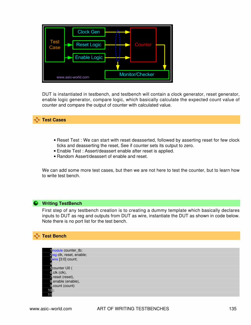
DUT is instantiated in testbench, and testbench will contain a clock generator, reset generator,enable logic generator, compare logic, which basically calculate the expected count value ofcounter and compare the output of counter with calculated value.
Test Cases
Reset Test : We can start with reset deasserted, followed by asserting reset for few clockticks and deasserting the reset, See if counter sets its output to zero.
•
Enable Test : Assert/deassert enable after reset is applied.• Random Assert/deassert of enable and reset.•
We can add some more test cases, but then we are not here to test the counter, but to learn howto write test bench.
Writing TestBenchFirst step of any testbench creation is to creating a dummy template which basically declaresinputs to DUT as reg and outputs from DUT as wire, instantiate the DUT as shown in code below.Note there is no port list for the test bench.
Test Bench
1module counter_tb;2reg clk, reset, enable;3wire [3:0] count;45counter U0 (6.clk (clk),7.reset (reset),8.enable (enable),9.count (count)
10);11
www.asic−world.com ART OF WRITING TESTBENCHES 135

12endmodule
Next step would be to add clock generator logic, this is straight forward, as we know how togenerate clock. Before we add clock generator we need to drive all the inputs to DUT to someknow state as shown in code below.
Test Bench with Clock gen
1module counter_tb;2reg clk, reset, enable;3wire [3:0] count;45counter U0 (6.clk (clk),7.reset (reset),8.enable (enable),9.count (count)
10);1112initial13begin
14 clk = 0;15 reset = 0;16 enable = 0;17end1819always20#5 clk = !clk;2122endmodule
Initial block in verilog is executed only once, thus simulator sets the value of clk, reset and enableto 0, which by looking at the counter code (of course you will be referring to the the DUT specs)could be found that driving 0 makes all this signals disabled.
There are many ways to generate clock, one could use forever loop inside a initial block as analternate to above code. You could add parameter or use `define to control the clock frequency.You may writing complex clock generator, where we could introduce PPM ( Parts per million, clockwidth drift), control the duty cycle. All the above depends on the specs of the DUT and creativity ofa "Test Bench Designer".
At this point, you would like test if the testbench is generating the clock correctly, well you cancompile with the Veriwell command line compiler found here. You need to give command lineoption as shown below. (Please let me know if this is illegal to have this compiler local to thiswebsite).
C:\www.asic−world.com\veridos counter.v counter_tb.v
www.asic−world.com ART OF WRITING TESTBENCHES 136

Of course it is a very good idea to keep file names same as module name. Ok, coming back tocompiling, you will see that simulator does not come out, or print anything on screen or does itdump any waveform. Thus we need to add support for all the above as shown in code below.
Test Bench continues...
1module counter_tb;2reg clk, reset, enable;3wire [3:0] count;45counter U0 (6.clk (clk),7.reset (reset),8.enable (enable),9.count (count)
10);1112initial begin13 clk = 0;14 reset = 0;15 enable = 0;16end1718always19#5 clk = !clk;2021initial begin22 $dumpfile ( "counter.vcd" );23 $dumpvars;24end2526initial begin27 $display( "\t\ttime,\tclk,\treset,\tenable,\tcount" );28 $monitor( "%d,\t%b,\t%b,\t%b,\t%d" ,$time, clk,reset,enable,count);29end3031initial32#100 $finish;3334//Rest of testbench code after this line3536endmodule
$dumpfile is used for specifying the file that simulator will use to store the waveform, that can beused later to view using waveform viewer. (Please refer to tools section for freeware version ofviewers.) $dumpvars basically instructs the Verilog compiler to start dumping all the signals to"counter.vcd".
$display is used for printing text or variables to stdout (screen), \t is for inserting tab. Syntax issame as printf. Second line $monitor is bit different, $monitor keeps track of changes to thevariables that are in the list (clk, reset, enable, count). When ever anyone of them changes, itprints their value, in the respective radix specified.
www.asic−world.com ART OF WRITING TESTBENCHES 137

$finish is used for terminating simulation after #100 time units (note, all the initial, always blocksstart execution at time 0)
Now that we have written basic skeleton, lets compile and see what we have just coded. Output ofthe simulator is shown below.
C:\www.asic−world.com>veridos counter.v counter_tb.v VeriWell for Win32 HDL Version 2.1.4 Fri Jan 17 21:33:25 2003
This is a free version of the VeriWell for Win32 Simulator Distribute this freely; call 1−800−VERIWELL for ordering information See the file "!readme.1st" for more information
Copyright (c) 1993−97 Wellspring Solutions, Inc. All rights reserved
Memory Available: 0 Entering Phase I... Compiling source file : counter.v Compiling source file : counter_tb.v The size of this model is [2%, 5%] of the capacity of the free version
Entering Phase II... Entering Phase III... No errors in compilation Top−level modules: counter_tb
time clk, reset, enable, count 0, 0, 0, 0, x 5, 1, 0, 0, x 10, 0, 0, 0, x 15, 1, 0, 0, x 20, 0, 0, 0, x 25, 1, 0, 0, x 30, 0, 0, 0, x 35, 1, 0, 0, x 40, 0, 0, 0, x 45, 1, 0, 0, x 50, 0, 0, 0, x 55, 1, 0, 0, x 60, 0, 0, 0, x 65, 1, 0, 0, x 70, 0, 0, 0, x 75, 1, 0, 0, x 80, 0, 0, 0, x 85, 1, 0, 0, x 90, 0, 0, 0, x 95, 1, 0, 0, x
Exiting VeriWell for Win32 at time 100 0 Errors, 0 Warnings, Memory Used: 0 Compile time = 0.0 Load time = 0.0 Simulation time = 0.1
Normal exit Thank you for using VeriWell for Win32
www.asic−world.com ART OF WRITING TESTBENCHES 138

Adding Reset Logic
Once we have the basic logic to allow us to see what our testbench is doing, we can next add thereset logic, If we look at the testcases, we see that we had added a constraint that it should bepossible to activate reset anytime during simulation. To achieve this we have many approaches,but I am going to teach something that will go long way. There is something called 'events' inVerilog, events can be triggered, and also monitored to see, if a event has occurred.
Lets code our reset logic in such a way that it waits for the trigger event "reset_trigger" to happen,when this event happens, reset logic asserts reset at negative edge of clock and de−asserts onnext negative edge as shown in code below. Also after de−asserting the reset, reset logic triggersanother event called "reset_done_trigger". This trigger event can then be used at some where elsein test bench to sync up.
Code of reset logic
1event reset_trigger;2event reset_done_trigger;34initial begin5 forever begin
6 @ (reset_trigger);7 @ (negedge clk);8 reset = 1;9 @ (negedge clk);
10 reset = 0;11 −> reset_done_trigger;12 end
13end
Adding test case logic
Moving forward, lets add logic to generate the test cases, ok we have three testcases as in the first
part of this tutorial. Lets list them again.
Reset Test : We can start with reset deasserted, followed by asserting reset for few clockticks and deasserting the reset, See if counter sets its output to zero.
•
Enable Test : Assert/deassert enable after reset is applied.• Random Assert/deassert of enable and reset.•
Repeating it again "There are many ways" to code a test case, it all depends on the creativity ofthe Test bench designer. Lets take a simple approach and then slowly build upon it.
Test Case 1 − Asserting/ Deasserting reset
www.asic−world.com ART OF WRITING TESTBENCHES 139

In this test case, we will just trigger the event reset_trigger after 10 simulation units.
1initial2begin: TEST_CASE3 #10 −> reset_trigger;4end
Test Case 2 − Assert/ Deassert enable after reset is applied.In this test case, we will trigger the reset logic and wait for the reset logic to complete its operation,before we start driving enable signal to logic 1.
1initial2begin: TEST_CASE3 #10 −> reset_trigger;4 @ (reset_done_trigger);5 @ (negedge clk);6 enable = 1;7 repeat (10) begin
8 @ (negedge clk);9 end
10 enable = 0;11end
Test Case 3 − Assert/Deassert enable and reset randomly.In this testcase we assert the reset, and then randomly drive values on to enable and reset signal.
1initial2begin : TEST_CASE3 #10 −> reset_trigger;4 @ (reset_done_trigger);5 fork
6 repeat (10) begin
7 @ (negedge clk);8 enable = $random;9 end
10 repeat (10) begin
11 @ (negedge clk);12 reset = $random;13 end
14 join
15end
Well you might ask, are all this three test case exist in same file, well the answer is no. If we try tohave all three test cases on one file, then we end up having race condition due to three initialblocks driving reset and enable signal. So normally, once test bench coding is done, test cases arecoded separately and included in testbench as `include directive as shown below. ( There arebetter ways to do this, but you have to think how you want to do it ).
www.asic−world.com ART OF WRITING TESTBENCHES 140

If you look closely all the three test cases, you will find that, even through test case execution isnot complete, simulation terminates. To have better control, what we can do is, add a event like"terminate_sim" and execute $finish only when this event is triggered. We can trigger this event atthe end of test case execution. The code for $finish now could look as below.
1event terminate_sim;2initial begin3 @ (terminate_sim);4 #5 $finish;5end
and the modified test case #2 would like.
1initial2begin: TEST_CASE3 #10 −> reset_trigger;4 @ (reset_done_trigger);5 @ (negedge clk);6 enable = 1;7 repeat (10) begin
8 @ (negedge clk);9 end
10 enable = 0;11 #5 −> terminate_sim;12end13
Second problem with the approach that we have taken till now it that, we need to manually checkthe waveform and also the output of simulator on the screen to see if the DUT is working correctly.Part IV shows how to automate this.
Adding compare Logic
To make any testbench self checking/automated, first we need to develop model that mimics theDUT in functionality. In our example, to mimic DUT, it going to be very easy, but at times if DUT iscomplex, then to mimic the DUT will be a very complex and requires lot of innovative techniques tomake self checking work.
1reg [3:0] count_compare;23always @ (posedge clk)4if (reset == 1'b1) begin5 count_compare <= 0;6end else if ( enable == 1'b1) begin7 count_compare <= count_compare + 1;8end
www.asic−world.com ART OF WRITING TESTBENCHES 141

Once we have the logic to mimic the DUT functionality, we need to add the checker logic, which atany given point keeps checking the expected value with the actual value. Whenever there is anyerror, it print's out the expected and actual value, and also terminates the simulation by triggeringthe event "terminate_sim".
1always @ (posedge clk)2if (count_compare != count) begin3 $display ( "DUT Error at time %d" , $time);4 $display ( " Expected value %d, Got Value %d" , count_compare, count);5 #5 −> terminate_sim;6end
Now that we have the all the logic in place, we can remove $display and $monitor, as ourtestbench have become fully automatic, and we don't require to manually verify the DUT input andoutput. Try changing the count_compare = count_compare +2, and see how compare logic works.This is just another way to see if our testbench is stable.
We could add some fancy printing as shown in the figure below to make our test env more friendly.
C:\Download\work>veridos counter.v counter_tb.v VeriWell for Win32 HDL Sat Jan 18 20:10:35 2003
This is a free version of the VeriWell for Win32 Simulator Distribute this freely; call 1−800−VERIWELL for ordering information See the file "!readme.1st" for more information
Copyright (c) 1993−97 Wellspring Solutions, Inc. All rights reserved
Memory Available: 0 Entering Phase I... Compiling source file : counter.v Compiling source file : counter_tb.v The size of this model is [5%, 6%] of the capacity of the free version
Entering Phase II... Entering Phase III... No errors in compilation Top−level modules: counter_tb
############################################ Applying reset Came out of Reset Terminating simulation Simulation Result : PASSED ########################################### Exiting VeriWell for Win32 at time 96 0 Errors, 0 Warnings, Memory Used: 0 Compile time = 0.0, Load time = 0.0, Simulation time = 0.0
Normal exit Thank you for using VeriWell for Win32
www.asic−world.com ART OF WRITING TESTBENCHES 142

I know, you would like to see the test bench code that I used to generate above output, well youcan find it here and counter code here.
There are lot of things that I have not covered, may be when I find time, I may add some moredetails on this subject.
As of books, I am yet to find a good book on writing test benches.
www.asic−world.com ART OF WRITING TESTBENCHES 143

NOTES−−
−−
−−
−−
−−
−−
−−
−−
−−
−−
−−
−−
−−
−−
−−
−−
−−
−−
−−
−−
−−
−−
−−
−−
−−
−−
−−
−−
−−
−−
−−
−−
−−
−−
−−
−−
−−
−−
www.asic−world.com ART OF WRITING TESTBENCHES 144
MODELING MEMORIES AND FSMCHAPTER 14
www.asic−world.com MODELING MEMORIES AND FSM 145

Memory ModelingTo help modeling of memory, Verilog provides support of two dimension arrays. Behavioral modelsof memories are modeled by declaring an array of register variables, any word in the array may beaccessed by using an index into the array. A temporary variable is required to access a discrete bitwithin the array.
Syntax
reg [wordsize:0] array_name [0:arraysize]
Examples
Declarationreg [7:0] my_memory [0:255];
Here [7:0] is width of memory and [0:255] is depth of memory with following parameters
Width : 8 bits, little endian• Depth : 256, address 0 corresponds to location 0 in array.•
Storing Valuesmy_memory[address] = data_in;
Reading Valuesdata_out = my_memory[address];
Bit ReadSometime there may be need to just read only one bit. Unfortunately Verilog does not allow to readonly or write only one bit, the work around for such a problem is as shown below.
data_out = my_memory[address];
data_out_it_0 = data_out[0];
Initializing Memories
A memory array may be initialized by reading memory pattern file from disk and storing it on thememory array. To do this, we use system task $readmemb and $readmemh. $readmemb is usedfor binary representation of memory content and $readmemh for hex representation.
Syntax$readmemh("file_name",mem_array,start_addr,stop_addr);
www.asic−world.com MODELING MEMORIES AND FSM 146

Note : start_addr and stop_addr are optional.
Example − Simple memory
1module memory();2reg [7:0] my_memory [0:255];34initial begin5 $readmemh( "memory.list" , my_memory);6end7endmodule
Example − Memory.list file
1//Comments are allowed21100_1100 // This is first address i.e 8'h0031010_1010 // This is second address i.e 8'h014@ 55 // Jump to new address 8'h5550101_1010 // This is address 8'h5560110_1001 // This is address 8'h56
$readmemh system task can also be used for reading test bench vectors. I will cover this in detailin test bench section. When I find time.
Refer to the examples section for more details on different types of memories.
Introduction to FSMState machine or FSM are the heart of any digital design, of course counter is a simple form ofFSM. When I was learning Verilog, I use to wonder "How do I code FSM in Verilog" and "What isthe best way to code it". I will try to answer the first part of the question below and second part ofthe question could be found in the tidbits section.
State machine TypesThere are two types of state machines as classified by the types of outputs generated from each.The first is the Moore State Machine where the outputs are only a function of the present state, thesecond is the Mealy State Machine where one or more of the outputs are a function of the presentstate and one or more of the inputs.
Mealy Model
www.asic−world.com MODELING MEMORIES AND FSM 147

Moore Model
State machines can also be classified based on type state encoding used. Encoding style is also acritical factor which decides speed, and gate complexity of the FSM. Binary, gray, one hot, onecold, and almost one hot are the different types of encoding styles used in coding FSM states.
Modeling State machines.
One thing that need to be kept in mind when coding FSM is that, combinational logic andsequence logic should be in two different always blocks. In the above two figures, next state logicis always the combinational logic. State Registers and Output logic are sequential logic. It is veryimportant that any asynchronous signal to the next state logic should be synchronized beforefeeding to FSM. Always try to keep FSM in separate Verilog file.
Using constants declaration like parameter or `define to define states of the FSM, this makes codemore readable and easy to manage.
Example − Arbiter
We will be using the arbiter FSM to study FSM coding styles in Verilog.
www.asic−world.com MODELING MEMORIES AND FSM 148

Verilog CodeFSM code should have three sections,
Encoding style.• Combinational part.• Sequential part.•
Encoding Style
There are many encoding styles around, some of which are
Binary Encoding• One Hot Encoding• One Cold Encoding• Almost One Hot Encoding• Almost One Cold Encoding• Gray Encoding•
Of all the above types we normally use one hot and binary encoding.
One Hot Encoding
1parameter [4:0] IDLE = 5'b0_0001;2parameter [4:0] GNT0 = 5'b0_0010;3parameter [4:0] GNT1 = 5'b0_0100;4parameter [4:0] GNT2 = 5'b0_1000;5parameter [4:0] GNT3 = 5'b1_0000;
Binary Encoding
www.asic−world.com MODELING MEMORIES AND FSM 149

1parameter [2:0] IDLE = 3'b000;2parameter [2:0] GNT0 = 3'b001;3parameter [2:0] GNT1 = 3'b010;4parameter [2:0] GNT2 = 3'b011;5parameter [2:0] GNT3 = 3'b100;
Gray Encoding
1parameter [2:0] IDLE = 3'b000;2parameter [2:0] GNT0 = 3'b001;3parameter [2:0] GNT1 = 3'b011;4parameter [2:0] GNT2 = 3'b010;5parameter [2:0] GNT3 = 3'b110;
Combinational Section
This section can be modeled using function, assign statement or using always block with casestatement. For time being lets see always block version
1always @ (state or req_0 or req_1)2begin
3 next_state = 0;4 case(state)5 IDLE : if (req_0 == 1'b1) begin
6 next_state = GNT0;7 end else if (req_1 == 1'b1) begin
8 next_state= GNT1;9 end else if (req_2 == 1'b1) begin
10 next_state= GNT2;11 end else if (req_3 == 1'b1) begin
12 next_state= GNT3;13 end else begin
14 next_state = IDLE;15 end
16 GNT0 : if (req_0 == 1'b0) begin
17 next_state = IDLE;18 end else begin
19 next_state = GNT0;20 end
21 GNT1 : if (req_1 == 1'b0) begin
22 next_state = IDLE;23 end else begin
24 next_state = GNT1;25 end
26 GNT2 : if (req_2 == 1'b0) begin
27 next_state = IDLE;28 end else begin
29 next_state = GNT2;
www.asic−world.com MODELING MEMORIES AND FSM 150

30 end
31 GNT3 : if (req_3 == 1'b0) begin
32 next_state = IDLE;33 end else begin
34 next_state = GNT3;35 end
36 default : next_state = IDLE;37 endcase
38end
Sequential Section
This section has be modeled using only edge sensitive logic such as always block with posedge ornegedge of clock
1always @ (posedge clock)2begin : OUTPUT_LOGIC3 if (reset == 1'b1) begin
4 gnt_0 <= #1 1'b0;5 gnt_1 <= #1 1'b0;6 gnt_2 <= #1 1'b0;7 gnt_3 <= #1 1'b0;8 state <= #1 IDLE;9 end else begin
10 state <= #1 next_state;11 case(state)12 IDLE : begin
13 gnt_0 <= #1 1'b0;14 gnt_1 <= #1 1'b0;15 gnt_2 <= #1 1'b0;16 gnt_3 <= #1 1'b0;17 end
18 GNT0 : begin
19 gnt_0 <= #1 1'b1;20 end
21 GNT1 : begin
22 gnt_1 <= #1 1'b1;23 end
24 GNT2 : begin
25 gnt_2 <= #1 1'b1;26 end
27 GNT3 : begin
28 gnt_3 <= #1 1'b1;29 end
30 default : begin
31 state <= #1 IDLE;32 end
33 endcase
34 end
35end
www.asic−world.com MODELING MEMORIES AND FSM 151

Full Code using binary encoding
1module fsm_full(2clock , // Clock3reset , // Active high reset4req_0 , // Active high request from agent 05req_1 , // Active high request from agent 16req_2 , // Active high request from agent 27req_3 , // Active high request from agent 38gnt_0 , // Active high grant to agent 09gnt_1 , // Active high grant to agent 1
10gnt_2 , // Active high grant to agent 211gnt_3 // Active high grant to agent 312);13// Port declaration here14input clock ; // Clock15input reset ; // Active high reset16input req_0 ; // Active high request from agent 017input req_1 ; // Active high request from agent 118input req_2 ; // Active high request from agent 219input req_3 ; // Active high request from agent 320output gnt_0 ; // Active high grant to agent 021output gnt_1 ; // Active high grant to agent 122output gnt_2 ; // Active high grant to agent 223output gnt_3 ; // Active high grant to agent2425// Internal Variables26reg gnt_0 ; // Active high grant to agent 027reg gnt_1 ; // Active high grant to agent 128reg gnt_2 ; // Active high grant to agent 229reg gnt_3 ; // Active high grant to agent3031parameter [2:0] IDLE = 3'b000;32parameter [2:0] GNT0 = 3'b001;33parameter [2:0] GNT1 = 3'b010;34parameter [2:0] GNT2 = 3'b011;35parameter [2:0] GNT3 = 3'b100;3637reg [2:0] state, next_state;3839always @ (state or req_0 or req_1 or req_2 or req_3)40begin
41 next_state = 0;42 case(state)43 IDLE : if (req_0 == 1'b1) begin
44 next_state = GNT0;45 end else if (req_1 == 1'b1) begin
46 next_state= GNT1;47 end else if (req_2 == 1'b1) begin
48 next_state= GNT2;49 end else if (req_3 == 1'b1) begin
www.asic−world.com MODELING MEMORIES AND FSM 152

50 next_state= GNT3;51 end else begin
52 next_state = IDLE;53 end
54 GNT0 : if (req_0 == 1'b0) begin
55 next_state = IDLE;56 end else begin
57 next_state = GNT0;58 end
59 GNT1 : if (req_1 == 1'b0) begin
60 next_state = IDLE;61 end else begin
62 next_state = GNT1;63 end
64 GNT2 : if (req_2 == 1'b0) begin
65 next_state = IDLE;66 end else begin
67 next_state = GNT2;68 end
69 GNT3 : if (req_3 == 1'b0) begin
70 next_state = IDLE;71 end else begin
72 next_state = GNT3;73 end
74 default : next_state = IDLE;75 endcase
76end7778always @ (posedge clock)79begin : OUTPUT_LOGIC80 if (reset) begin
81 gnt_0 <= #1 1'b0;82 gnt_1 <= #1 1'b0;83 gnt_2 <= #1 1'b0;84 gnt_3 <= #1 1'b0;85 state <= #1 IDLE;86 end else begin
87 state <= #1 next_state;88 case(state)89 IDLE : begin
90 gnt_0 <= #1 1'b0;91 gnt_1 <= #1 1'b0;92 gnt_2 <= #1 1'b0;93 gnt_3 <= #1 1'b0;94 end
95 GNT0 : begin
96 gnt_0 <= #1 1'b1;97 end
98 GNT1 : begin
99 gnt_1 <= #1 1'b1;100 end
www.asic−world.com MODELING MEMORIES AND FSM 153

101 GNT2 : begin
102 gnt_2 <= #1 1'b1;103 end
104 GNT3 : begin
105 gnt_3 <= #1 1'b1;106 end
107 default : begin
108 state <= #1 IDLE;109 end
110 endcase
111 end
112end113114endmodule
Testbench1`include "fsm_full.v"23module fsm_full_tb();4reg clock , reset ;5reg req_0 , req_1 , req_2 , req_3;6wire gnt_0 , gnt_1 , gnt_2 , gnt_3 ;78initial begin9 $display( "Time\t R0 R1 R2 R3 G0 G1 G2 G3" );
10 $monitor( "%g\t %b %b %b %b %b %b %b %b" , $time, req_0, req_1, req_2, req_3, gnt_0, gnt_1, gnt_2, gnt_3);11 clock = 0;12 reset = 0;13 req_0 = 0;14 req_1 = 0;15 req_2 = 0;16 req_3 = 0;17 #10 reset = 1;18 #10 reset = 0;19 #10 req_0 = 1;20 #20 req_0 = 0;21 #10 req_1 = 1;22 #20 req_1 = 0;23 #10 req_2 = 1;24 #20 req_2 = 0;25 #10 req_3 = 1;26 #20 req_3 = 0;27 #10 $finish;28end2930always31#2 clock = ~clock;323334fsm_full U_fsm_full(35clock , // Clock36reset , // Active high reset37req_0 , // Active high request from agent 0
www.asic−world.com MODELING MEMORIES AND FSM 154

38req_1 , // Active high request from agent 139req_2 , // Active high request from agent 240req_3 , // Active high request from agent 341gnt_0 , // Active high grant to agent 042gnt_1 , // Active high grant to agent 143gnt_2 , // Active high grant to agent 244gnt_3 // Active high grant to agent 345);46474849endmodule
Simulator Output Time R0 R1 R2 R3 G0 G1 G2 G3 0 0 0 0 0 x x x x 7 0 0 0 0 0 0 0 0 30 1 0 0 0 0 0 0 0 35 1 0 0 0 1 0 0 0 50 0 0 0 0 1 0 0 0 55 0 0 0 0 0 0 0 0 60 0 1 0 0 0 0 0 0 67 0 1 0 0 0 1 0 0 80 0 0 0 0 0 1 0 0 87 0 0 0 0 0 0 0 0 90 0 0 1 0 0 0 0 0 95 0 0 1 0 0 0 1 0 110 0 0 0 0 0 0 1 0 115 0 0 0 0 0 0 0 0 120 0 0 0 1 0 0 0 0 127 0 0 0 1 0 0 0 1 140 0 0 0 0 0 0 0 1 147 0 0 0 0 0 0 0 0
www.asic−world.com MODELING MEMORIES AND FSM 155

NOTES−−
−−
−−
−−
−−
−−
−−
−−
−−
−−
−−
−−
−−
−−
−−
−−
−−
−−
−−
−−
−−
−−
−−
−−
−−
−−
−−
−−
−−
−−
−−
−−
−−
−−
−−
−−
−−
−−
www.asic−world.com MODELING MEMORIES AND FSM 156
PARAMETERIZED MODULESCHAPTER 15
www.asic−world.com PARAMETERIZED MODULES 157

IntroductionLets assume that we have a design, which requires us to have counters of various width, but ofsame functionality. May be we can assume that we have a design which requires lot of instants ofdifferent depth and width of RAM's of same functionality. Normally what we do is, create countersof different widths and then use them. Same rule applies to RAM that we talked about.
But Verilog provides a powerful way to work around this problem, it provides us with somethingcalled parameter, these parameters are like constants local to that particular module.
We can override the default values with either using defparam or by passing new set ofparameters during instantiating. We call this as parameter over riding.
ParametersA parameter is defined by Verilog as a constant value declared within the module structure. Thevalue can be used to define a set of attributes for the module which can characterize its behavioras well as its physical representation.
Defined inside a module.• Local scope.• May be overridden at instantiation time•
If multiple parameters are defined, they must be overridden in the order they weredefined. If an overriding value is not specified, the default parameter declarationvalues are used.
♦
May be changed using the defparam statement•
Parameter Override using defparam
1module secret_number;2parameter my_secret = 0;34initial begin5 $display( "My secret number is %d" , my_secret);6end78endmodule9
10module defparam_example();1112defparam U0.my_secret = 11;13defparam U1.my_secret = 22;1415secret_number U0();16secret_number U1();1718endmodule
Parameter Override during instantiating.
www.asic−world.com PARAMETERIZED MODULES 158

1module secret_number;2parameter my_secret = 0;34initial begin5 $display( "My secret number in module is %d" , my_secret);6end78endmodule9
10module param_overide_instance_example();1112secret_number #(11) U0();13secret_number #(22) U1();1415endmodule
Passing more then one parameter
1module ram_sp_sr_sw (2clk , // Clock Input3address , // Address Input4data , // Data bi−directional5cs , // Chip Select6we , // Write Enable/Read Enable7oe // Output Enable8);9
10parameter DATA_WIDTH = 8 ;11parameter ADDR_WIDTH = 8 ;12parameter RAM_DEPTH = 1 << ADDR_WIDTH;13// Actual code of RAM here1415endmodule
When instantiating more then the one parameter, parameter values should be passed in order theyare declared in sub module.
1module ram_controller (); //Some ports23// Controller Code45ram_sp_sr_sw #(16,8,256) ram(clk,address,data,cs,we,oe);67endmodule
Verilog 2001In Verilog 2001, above code will work, but the new feature makes the code more readable anderror free.
www.asic−world.com PARAMETERIZED MODULES 159

1module ram_controller (); //Some ports23ram_sp_sr_sw #(4.DATA_WIDTH(16),5.ADDRE_WIDTH(8),6.RAM_DEPTH(256)) ram(clk,address,data,cs,we,oe);78endmodule
Was this copied from VHDL?
www.asic−world.com PARAMETERIZED MODULES 160

NOTES−−
−−
−−
−−
−−
−−
−−
−−
−−
−−
−−
−−
−−
−−
−−
−−
−−
−−
−−
−−
−−
−−
−−
−−
−−
−−
−−
−−
−−
−−
−−
−−
−−
−−
−−
−−
−−
−−
www.asic−world.com PARAMETERIZED MODULES 161

VERILOG SYNTHESIS TUTORIALCHAPTER 16
www.asic−world.com VERILOG SYNTHESIS TUTORIAL 162

What is logic synthesis ?Logic synthesis is the process of converting a high−level description of design into an optimizedgate−level representation. Logic synthesis uses standard cell library which have simple cells, suchas basic logic gates like and, or, and nor, or macro cells, such as adder, muxes, memory, andflip−flops. Standard cells put together is called technology library. Normally technology library isknow by the transistor size (0.18u, 90nm).
A circuit description is written in Hardware description language (HDL) such as Verilog. Thedesigner should first understand the architectural description. Then he should consider designconstraints such as timing, area, testability, and power.
We will see a typical design flow with a large example in last chapter of Verilog tutorial.
Life before HDL (Logic synthesis)
As you must have experienced in college, every thing (all the digital circuits) is designed manually.Draw K−maps, optimize the logic, Draw the schematic. This is how engineers used to designdigital logic circuits in early days. Well this works fine as long as the design is few hundred gates.
Impact of HDL and Logic synthesis.
High−level design is less prone to human error because designs are described at a higher level ofabstraction. High−level design is done without significant concern about design constraints.Conversion from high−level design to gates is done by synthesis tools, while doing so it usedvarious algorithms to optimize the design as a whole. This removes the problem with varieddesigner styles for the different blocks in the design and suboptimal designs. Logic synthesis toolsallow technology independent design. Design reuse is possible for technology−independentdescriptions.
What do we discuss here ?
When it comes to Verilog, the synthesis flow is same as rest of the languages. What we intent tolook in next few pages is how particular code gets translated to gates. As you must have wonderedwhile reading earlier chapters, how could this be represented in Hardware. Example would be"delays". There is no way we could synthesize delays, but of course we can add delay to particular
www.asic−world.com VERILOG SYNTHESIS TUTORIAL 163

signal by adding buffers. But then this becomes too dependent on synthesis target technology.(More on this in VLSI section).
First we will look at the constructs that are not supported by synthesis tools, Table below showsthe constructs that are supported by the synthesis tool.
Constructs Not Supported in Synthesis
Construct Type Notes
initial Used only in test benches.
events Events make more sense for syncing test bench components
real Real data type not supported.
time Time data type not supported
force and release Force and release of data types not supported
assign and deassign assign and deassign of reg data types is not supported. Butassign on wire data type is supported
fork join Use nonblocking assignments to get same effect.
primitives Only gate level primitives are supported
table UDP and tables are not supported.
Example of Non−Synthesizable Verilog construct.
Any code that contains above constructs are not synthesizable, but within synthesizableconstructs, bad coding could cause synthesis issues. I have seen codes where engineers code aflip−flop with both posedge of clock and negedge of clock in sensitivity list.
Then we have another common type of code, where one reg variable is driven from more then onealways blocks. Well it will surely cause synthesis error.
Example − Initial Statement
1module synthesis_initial(2clk,q,d);3input clk,d;4output q;5reg q;67initial begin8 q <= 0;9end
1011always @ (posedge clk)12begin
www.asic−world.com VERILOG SYNTHESIS TUTORIAL 164

13 q <= d;14end1516endmodule
Delaysa = #10 b; This code is useful only for simulation purpose.
Synthesis tool normally ignores such constructs, and just assumes that there is no #10 in abovestatement. Thus treating above code as below.
a = b;
Comparison to X and Z are always ignored
1module synthesis_compare_xz (a,b);2output a;3input b;4reg a;56always @ (b)7begin
8 if ((b == 1'bz) || (b == 1'bx)) begin
9 a = 1;10 end else begin
11 a = 0;12 end
13end1415endmodule
There seems to a common problem with all the new to hardware design engineers. They normallytend to compare variables with X and Z. In practice it is worst thing to do. So please avoidcomparing with X and Z. Limit your design to two state's, 0 and 1. Use tri−state only at chip IOpads level. We will see this as a example in next few pages.
Constructs Supported in SynthesisVerilog is such a simple language, you could easily write code which is easy to understand andeasy to map to gates. Code which uses if, case statements are simple and cause little headache'swith synthesis tools. But if you like fancy coding and like to have some trouble. Ok don't be scared,you could use them after you get some experience with Verilog. Its great fun to use high levelconstructs, saves time.
Most common way to model any logic is to use either assign statement or always block. assignstatement can be used for modeling only combinational logic and always can be used for modelingboth combinational and Sequential logic.
www.asic−world.com VERILOG SYNTHESIS TUTORIAL 165

Construct Type Keyword or Description Notes
ports input, inout, output Use inout only at IO level.
parameters parameter This makes design more generic
module definition module
signals and variables wire, reg, tri Vectors are allowed
instantiation module instances primitivegate instances
Eg− nand (out,a,b) bad idea to codeRTL this way.
function and tasks function , task Timing constructs ignored
procedural always, if, then, else, case,casex, casez initial is not supported
procedural blocks begin, end, named blocks,disable Disabling of named blocks allowed
data flow assign Delay information is ignored
named Blocks disable Disabling of named block supported.
loops for, while, foreverWhile and forever loops mustcontain @(posedge clk) or@(negedge clk)
Operators and their Effect.
One common problem that seems to occure, getting confused with logical and Reductionoperators. So watch out.
Operator Type Operator Symbol Operation Performed
Arithmetic * Multiply
/ Division
+ Add
− Subtract
% Modulus
+ Unary plus
− Unary minus
Logical ! Logical negation
&& Logical and
|| Logical or
Relational > Greater than
< Less than
>= Greater than or equal
<= Less than or equal
Equality == Equality
!= inequality
www.asic−world.com VERILOG SYNTHESIS TUTORIAL 166

Reduction & Bitwise negation
~& nand
| or
~| nor
^ xor
^~ ~^ xnor
Shift >> Right shift
<< Left shift
Concatenation { } Concatenation
Conditional ? conditional
Logic Circuit ModelingFrom what we have learn in digital design, we know that there could be only two types of digitalcircuits. One is combinational circuits and second is sequential circuits. There are very few rulesthat need to be followed to get good synthesis output and avoid surprises.
Combinational Circuit Modeling using assign
Combinational circuits modeling in Verilog can be done using assign and always blocks. Writingsimple combination circuit in Verilog using assign statement is very straight forward. Like inexample below
assign y = (a&b) | (c^d);
Tri−state buffer
1module tri_buf (a,b,enable);2input a;3output b;4input enable;5wire b;67assign b = (enable) ? a : 1'bz;89endmodule
www.asic−world.com VERILOG SYNTHESIS TUTORIAL 167

Mux
1module mux_21 (a,b,sel,y);2input a, b;3output y;4input sel;5wire y;67assign y = (sel) ? b : a;89endmodule
Simple Concatenation
1module bus_con (a,b);2input [3:0] a, b;3output [7:0] y;4wire [7:0] y;56assign y = {a,b};78endmodule
1 bit adder with carry
1module addbit (2a , // first input3b , // Second input4ci , // Carry input5sum , // sum output6co // carry output7);8//Input declaration9input a;
10input b;11input ci;12//Ouput declaration13output sum;14output co;
www.asic−world.com VERILOG SYNTHESIS TUTORIAL 168

15//Port Data types16wire a;17wire b;18wire ci;19wire sum;20wire co;21//Code starts here22assign {co,sum} = a + b + ci;2324endmodule // End of Module addbit
Multiply by 2
1module muliply (a,product);2input [3:0] a;3output [4:0] product;4wire [4:0] product;56assign product = a << 1;78endmodule
3 is to 8 decoder
1module decoder (in,out);2input [2:0] in;3output [7:0] out;4wire [4:0] out;5assign out = (in == 3'b000 ) ? 8'b0000_0001 :6(in == 3'b001 ) ? 8'b0000_0010 :7(in == 3'b010 ) ? 8'b0000_0100 :8(in == 3'b011 ) ? 8'b0000_1000 :9(in == 3'b100 ) ? 8'b0001_0000 :
10(in == 3'b101 ) ? 8'b0010_0000 :11(in == 3'b110 ) ? 8'b0100_0000 :12(in == 3'b111 ) ? 8'b1000_0000 : 8'h00;1314endmodule
Combinational Circuit Modeling using always
While modeling using always statement, there is chance of getting latch after synthesis if propercare is not taken care. (no one seems to like latches in design, though they are faster, and takelesser transistor. This is due to the fact that timing analysis tools always have problem with latchesand second reason being, glitch at enable pin of latch is another problem).
One simple way to eliminate latch with always statement is, always drive 0 to the LHS variable inthe beginning of always code as shown in code below.
3 is to 8 decoder using always
www.asic−world.com VERILOG SYNTHESIS TUTORIAL 169

1module decoder_always (in,out);2input [2:0] in;3output [7:0] out;4reg [4:0] out;56always @ (in)7begin
8 out = 0;9 case (in)
10 3'b001 : out = 8'b0000_0001;11 3'b010 : out = 8'b0000_0010;12 3'b011 : out = 8'b0000_0100;13 3'b100 : out = 8'b0000_1000;14 3'b101 : out = 8'b0001_0000;15 3'b110 : out = 8'b0100_0000;16 3'b111 : out = 8'b1000_0000;17 endcase
18end1920endmodule
Sequential Circuit Modeling
Sequential logic circuits are modeled by use of edge sensitive elements in sensitive list of alwaysblocks. Sequential logic can be modeled only by use of always blocks. Normally we usenonblocking assignments for sequential circuits.
Simple Flip−Flop
1module flif_flop (clk,reset, q, d);2input clk, reset, d;3output q;4reg q;56always @ (posedge clk )7begin
8 if (reset == 1) begin
9 q <= 0;10 end else begin
11 q <= d;12 end
13end1415endmodule
Verilog Coding StyleIf you look at the above code, you will see that I have imposed coding style that looks cool. Everycompany has got its own coding guidelines and tools like linters to check for this coding guidelines.Below is small list of guidelines.
www.asic−world.com VERILOG SYNTHESIS TUTORIAL 170

Use meaningful names for signals and variables• Don't mix level and edge sensitive in one always block• Avoid mixing positive and negative edge−triggered flip−flops• Use parentheses to optimize logic structure• Use continuous assign statements for simple combo logic.• Use nonblocking for sequential and blocking for combo logic• Don't mix blocking and nonblocking assignments in one always block. (Though Designcompiler supports them!!).
•
Be careful with multiple assignments to the same variable• Define if−else or case statements explicitly.•
Note : Suggest if you want more details.
www.asic−world.com VERILOG SYNTHESIS TUTORIAL 171

NOTES−−
−−
−−
−−
−−
−−
−−
−−
−−
−−
−−
−−
−−
−−
−−
−−
−−
−−
−−
−−
−−
−−
−−
−−
−−
−−
−−
−−
−−
−−
−−
−−
−−
−−
−−
−−
−−
−−
www.asic−world.com VERILOG SYNTHESIS TUTORIAL 172

VERILOG PLI TUTORIALCHAPTER 17
www.asic−world.com VERILOG PLI TUTORIAL 173
IntroductionVerilog PLI( Programming Language Interface) is a mechanism to invoke C or C++ functions fromVerilog code.
The function invoked in Verilog code is called a system call. An example of a built−in system call is$display, $stop, $random. PLI allows the user to create custom system calls, Something thatVerilog syntax does not allow us to do. Some of this are:−
Power analysis.• Code coverage tools.• Can modify the Verilog simulation data structure − more accurate delays.• Custom output displays.• Co−simulation.• Design debug utilities.• Simulation analysis.• C−model interface to accelerate simulation.• Testbench modeling.•
To achieve above few application of PLI, C code should have the access to the internal datastructure of the Verilog simulator. To facilitate this Verilog PLI provides with something called accroutines or simply access routines.
There is second set of routines, which are called tf routines, or simply task and function routines.The tf and acc are PLI 1.0 routines and is very vast and very old routines. The next set of routine,which was introduced with latest release of Verilog 2001 is called vpi routines. This is small andcrystal clear PLI routines and thus the new version PLI 2.0.
You can get Verilog 2001 LRM or PLI 1.0 IEEE document for details of each and every functionsprovided. Verilog IEEE LRM's are written in such a way that anyone with hardware backgroundcan understand. If you are unable to get hold of above IEEE docs, then you can buy PLI bookslisted in books section.
How it Works
Write the functions in C/C++ code.• Compile them to generate shared lib ( *.DLL in Windows and *.so in UNIX). Simulator likeVCS allows static linking.
•
Use this Functions in Verilog code (Mostly Verilog Testbench).• Based on simulator, pass the C/C++ function details to simulator during compile process ofVerilog Code (This is called linking, and you need to refer to simulator user guide tounderstand how this is done).
•
Once linked just run the simulator like any other Verilog simulation.•
www.asic−world.com VERILOG PLI TUTORIAL 174
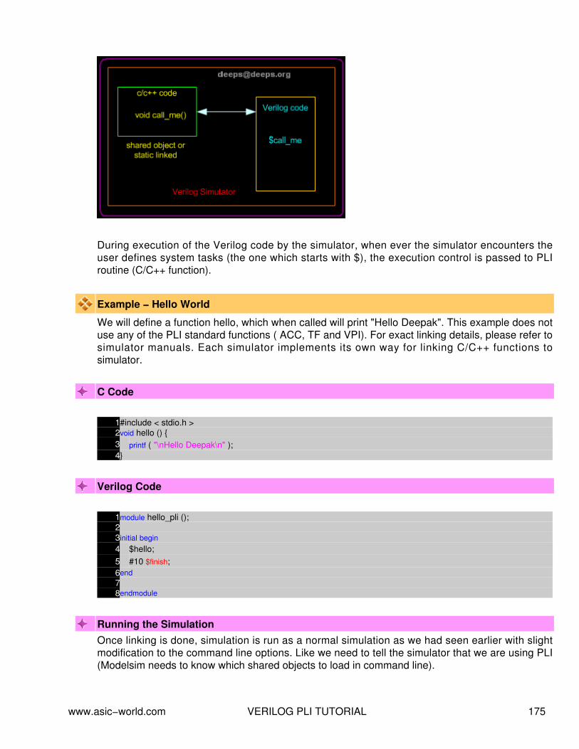
During execution of the Verilog code by the simulator, when ever the simulator encounters theuser defines system tasks (the one which starts with $), the execution control is passed to PLIroutine (C/C++ function).
Example − Hello World
We will define a function hello, which when called will print "Hello Deepak". This example does notuse any of the PLI standard functions ( ACC, TF and VPI). For exact linking details, please refer tosimulator manuals. Each simulator implements its own way for linking C/C++ functions tosimulator.
C Code
1#include < stdio.h >2void hello () {3 printf ( "\nHello Deepak\n" );4}
Verilog Code
1module hello_pli ();23initial begin4 $hello;5 #10 $finish;6end78endmodule
Running the SimulationOnce linking is done, simulation is run as a normal simulation as we had seen earlier with slightmodification to the command line options. Like we need to tell the simulator that we are using PLI(Modelsim needs to know which shared objects to load in command line).
www.asic−world.com VERILOG PLI TUTORIAL 175

Writing PLI Application
Example that we saw was too basic and is no good for any practical purpose. Lets consider ourinfamous counter example and write the DUT reference model and Checker in C and link that toVerilog Testbench. First lets list out the requirements for writing a C model using PLI.
Means of calling the C model, when ever there is change in input signals (Could be wire orreg or types).
•
Means to get the value of the changes signals in Verilog code or any other signals inVerilog code from inside the C code.
•
Means to drive the value on any signal inside the Verilog code from C code.• There are set of routines (functions), that Verilog PLI provides which satisfy above requirements.
PLI Application Specification.
Lets define the requirements for our infamous counter testbench requirements using PLI. We willcall out PLI function as $counter_monitor.
Implements a Counter logic in C.• Implements Checker logic in C.• Terminates the simulation, when ever checker fails.•
Calling the C function.
Writing counter in C is so cool, but when do we increment the counter value. Well we need tomonitor the change in clock signal. (Note : By the way, it normally good idea to drive reset andclock from Verilog code.) When ever the clock changes, counter function needs to be executed.This can be achieved by using below routine.
Use acc_vcl_add routine. The syntax of which can be found in Verilog PLI LRM.• acc_vcl_add routines basically allows us to monitor list of signals, and when ever any of themonitor signals change, it calls the user defined function (i.e this function is called Consumer C
www.asic−world.com VERILOG PLI TUTORIAL 176
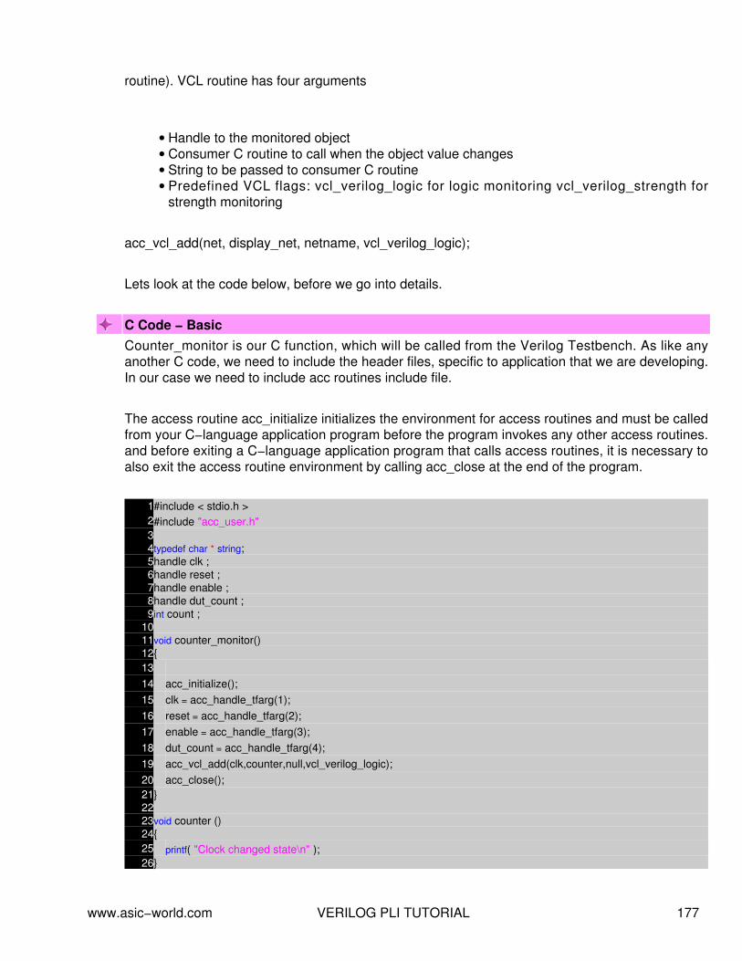
routine). VCL routine has four arguments
Handle to the monitored object• Consumer C routine to call when the object value changes• String to be passed to consumer C routine• Predefined VCL flags: vcl_verilog_logic for logic monitoring vcl_verilog_strength forstrength monitoring
•
acc_vcl_add(net, display_net, netname, vcl_verilog_logic);
Lets look at the code below, before we go into details.
C Code − BasicCounter_monitor is our C function, which will be called from the Verilog Testbench. As like anyanother C code, we need to include the header files, specific to application that we are developing.In our case we need to include acc routines include file.
The access routine acc_initialize initializes the environment for access routines and must be calledfrom your C−language application program before the program invokes any other access routines.and before exiting a C−language application program that calls access routines, it is necessary toalso exit the access routine environment by calling acc_close at the end of the program.
1#include < stdio.h >2#include "acc_user.h"34typedef char * string;5handle clk ;6handle reset ;7handle enable ;8handle dut_count ;9int count ;
1011void counter_monitor()12{1314 acc_initialize();15 clk = acc_handle_tfarg(1);16 reset = acc_handle_tfarg(2);17 enable = acc_handle_tfarg(3);18 dut_count = acc_handle_tfarg(4);19 acc_vcl_add(clk,counter,null,vcl_verilog_logic);20 acc_close();21}2223void counter ()24{25 printf( "Clock changed state\n" );26}
www.asic−world.com VERILOG PLI TUTORIAL 177

For accessing the Verilog objects, we use handle, A handle is a predefined data type that is apointer to a specific object in the design hierarchy. Each handle conveys information to accessroutines about a unique instance of an accessible object information about the object¿s type, plushow and where to find data about the object. But how do we pass the information of specific objectto handle. Well we can do this by number of ways, but for now, we will pass it from Verilog asparameters to $counter_monitor , this parameters can be accessed inside the C−program withacc_handle_tfarg() routine. Where the argument is numbers as in the code.
So clk = acc_handle_tfarg(1) basically makes the clk as the handle to first parameter passed.Similarly we assign all the handle's. Now we can add clk to the signal list that need to bemonitored using the routine acc_vcl_add(clk,counter,null,vcl_verilog_logic). Here clk is the handle,counter is the user function to execute, when clk changes.
The function counter() does not require any explation, it is simple Hello world type code.
Verilog CodeBelow is the code of the simple testbench for the counter example. We call the C−function usingthe syntax shown in code below. If object thats been passed is a instant, then it should be passedinside double quotes. Since all our objects are nets or wires, there is no need to pass them insidedouble quote.
1module counter_tb();2reg enable;;3reg reset;4reg clk_reg;5wire clk;6wire [3:0] count;78initial begin9 enable = 0;
10 clk = 0;11 reset = 0;12 $display( "Asserting reset" );13 #10 reset = 1;14 #10 reset = 0;15 $display ( "Asserting Enable" );16 #10 enable = 1;17 #20 enable = 0;18 $display ( "Terminating Simulator" );19 #10 $finish;20end2122always23#5 clk_reg = !clk_reg;2425assign clk = clk_reg;2627initial begin28 $counter_monitor(top.clk,top.reset,top.enable,top.count);29end
www.asic−world.com VERILOG PLI TUTORIAL 178

3031counter U(32.clk (clk),33.reset (reset),34.enable (enable),35.count (count)36);3738endmodule
Depending on the simulator in use, the compile and running various. When you run the codeabove with the C code seen earlier we get following output
Asserting reset Clock changed state Clock changed state Clock changed state Asserting Enable Clock changed state Clock changed state Clock changed state Clock changed state Clock changed state Clock changed state Terminating Simulator Clock changed state Clock changed state $finish at simulation time 60
C Code − FullSo now that we see that our function gets called whenever there is change in clock, we can writethe counter code. But wait, there is a problem, every time counter function makes a exit, the localvariables will loose its value. There are couple of ways we can preserve state of the variables.
Declare the counter variable as global• Use tf_setworkarea() and tf_getworkarea() routine to store and restore the values of thelocal variables.
•
Since we have only one variable, we can use the first solution. i.e. declare count as globalvariable.
To write equivalent model for the counter, clock, reset, enable signal input to DUT is required andto code checker, out of the DUT count is required. To read the values from the Verilog code, wehave PLI routine.
acc_fetch_value(handle,"formate")
but the value returned is a string, so we need to convert that into integer if, muli−bit vector signal isread using this routine. pli_conv is a function which does this conversion. Routine tf_dofinish() is
www.asic−world.com VERILOG PLI TUTORIAL 179

used for terminating simulation, when DUT and TB count value does not match or in other words,when simulation mismatch occurs.
Rest of the code is self explanatory. (Now time is 11:45PM, time to bed)
1#include < stdio.h >2#include "acc_user.h"34typedef char * string;5handle clk ;6handle reset ;7handle enable ;8handle dut_count ;9int count ;
1011void counter_monitor()12{1314 acc_initialize();15 clk = acc_handle_tfarg(1);16 reset = acc_handle_tfarg(2);17 enable = acc_handle_tfarg(3);18 dut_count = acc_handle_tfarg(4);19 acc_vcl_add(clk,counter,null,vcl_verilog_logic);20 acc_close();21}2223void counter ()24{2526 string i_reset = acc_fetch_value(reset, "%b" );27 string i_enable = acc_fetch_value(enable, "%b" );28 string i_count = acc_fetch_value(dut_count, "%b" );29 string i_clk = acc_fetch_value(clk, "%b" );30 string high = "1" ;31 int size_in_bits= acc_fetch_size (dut_count);32 int tb_count = 0;33 // Counter function goes here34 if (*i_reset == *high) {35 count = 0;36 }37 else if ((*i_enable == *high) && (*i_clk == *high)) {38 if ( count == 15 ) {39 count = 0;40 } else {41 count = count + 1;42 }43 // Counter Checker function goes herecker logic goes here44 if ((*i_clk != *high) && (*i_reset != *high)) {45 tb_count = pli_conv(i_count,size_in_bits);46 if (tb_count != count) {47 printf( "dut_error : Expect value %d, Got value %d\n" , count, tb_count);
www.asic−world.com VERILOG PLI TUTORIAL 180

48 tf_dofinish();49 }50 }51 }52 // Multi−bit vector to integer conversion.53 int pli_conv (string in_string,int no_bits)54 {55 int conv = 0;56 int i = 0;57 int j = 0;58 int bin = 0;59 for ( i = no_bits−1; i >= 0; i = i − 1) {60 if (*(in_string + i) == 49) {61 bin = 1;62 } else if (*(in_string + i) == 120) {63 printf ( "Warning : X detected" );64 bin = 0;65 } else if (*(in_string + i) == 122) {66 printf ( "Warning : Z detected" );67 bin = 0;68 } else {69 bin = 0;70 }71 conv = conv + (1 << j)*bin;72 j ++;73 }74 return conv;75 }
You can compile and simulate the above code with Simulator you have.
Note : There could be mistakes in the way I have written the code or taken the approach inexplaining PLI. Please mail me if you feel that it needs to be fixed or you have better way to showhow PLI tutorial should be written.
PLI Routines.PLI 1.0 provides two types of routines, they are
access routine• task and function routine.•
PLI 2.0 combined access routines and task and function routines into VPI routines, and alsoclarified the confusion in PLI 1.0.
www.asic−world.com VERILOG PLI TUTORIAL 181

Access Routines
Access routines are C programming language routines that provide procedural access toinformation within Verilog−HDL. Access routines perform one of two operations
Read Operation : read data about particular objects in your circuit design directly from internal datastructures. Access routines can read information about the following objects
Module instances• Module ports• Module paths• Inter−module paths• Top−level modules• Primitive instances• Primitive terminals• Nets• Registers• Parameters• Specparams• Timing checks• Named events• Integer, real and time variables•
Write Operation : Write new information about objects in your circuit design into the internal datastructures. Access routines can write to following objects.
Inter−module paths.• Module paths.• Primitive instances.• Timing checks.• Register logic values.• Sequential UDP logic values.•
Based on the operation performed by access routines, they are classified into 6 categories asshown below.
Fetch : This routines return a variety of information about different objects in the designhierarchy.
•
Handle : This routines return handles to a variety of objects in the design hierarchy.• Modify : This routines alter the values of a variety of objects in the design hierarchy.• Next : When used inside a loop construct, next routines find each object of a given typethat is related to a particular reference object in the design hierarchy.
•
Utility : This routines perform a variety of operations, such as initializing and configuring theaccess routine environment.
•
www.asic−world.com VERILOG PLI TUTORIAL 182

Vcl : The Value Change Link (VCL) allows a PLI application to monitor the value changesof selected objects.
•
Access Routines Reference
Routine Description
acc_handle_scope()
acc_handle_by_name()
acc_handle_by_object()
acc_handle_interactive_scope()
acc_handle_calling_mod_m()
acc_handle_parent()
acc_handle_port()
acc_handle_hiconn()
acc_handle_loconn()
acc_handle_path()
acc_handle_modpath()
acc_handle_datapath()
acc_handle_pathin()
acc_handle_pathout()
acc_handle_condition()
acc_handle_tchk()
acc_handle_notifier()
acc_handle_tchkarg1()
acc_handle_tchkarg2()
acc_handle_simulated_net()
acc_handle_terminal()
acc_handle_conn()
acc_handle_tfinst()
acc_handle_tfarg()
acc_handle_itfarg()
acc_fetch_argc()
acc_fetch_argv()
acc_fetch_attribute()
acc_fetch_attribute_int()
acc_fetch_attribute_str()
acc_fetch_paramtype()
acc_fetch_paramval()
www.asic−world.com VERILOG PLI TUTORIAL 183

acc_fetch_defname()
acc_fetch_fullname()
acc_fetch_name()
acc_fetch_delay_mode()
acc_fetch_delay()
acc_fetch_size()
acc_fetch_range()
acc_fetch_tfarg()
acc_fetch_itfarg()
acc_fetch_ifarg_int()
acc_fetch_itfarg_int()
acc_fetch_tfarg_str()
acc_fetch_itfarg_str()
acc_fetch_precision()
acc_fetch_timescale_info()
acc_fetch_direction()
acc_fetch_index()
acc_fetch_edge()
acc_fetch_polarity()
acc_fetch_pulsere()
acc_set_value()
acc_append_delays()
acc_replace_delays()
acc_initialize()
acc_close()
acc_configure()
acc_reset_buffer()
acc_product_type()
acc_product_version()
acc_version()
acc_set_scope()
acc_set_interactive_scope()
acc_count()
acc_collect()
acc_free()
acc_compare_handles()
acc_object_in_typelist()
acc_object_of_type()
www.asic−world.com VERILOG PLI TUTORIAL 184

acc_next_cell()
acc_next_child()
acc_next_modpath()
acc_next_net()
acc_next_parameter()
acc_next_port()
acc_next_portout()
acc_next_primitive()
acc_next_specparam()
acc_next_tchk()
acc_next_terminal()
acc_next_scope()
acc_next()
acc_next_topmod()
acc_next_cell_load()
acc_next_load()
acc_next_driver()
acc_next_hiconn()
acc_next_loconn()
acc_next_bit()
acc_next_input()
acc_next_output()
Program Flow using access routinesAs seen in the earlier example, there set of steps that need to be performed before we could writea user application. This can be shown as in the below program.
1#include < acc_user.h >23void pli_func() {4 acc_initialize();5 // Main body: Insert the user application code here6 acc_close();7}
acc_user.h : all data−structure related to access routines• acc_initialize() : initialize variables and set up environment• main body : User−defined application• acc_close() : Undo the actions taken by the function acc_initialize()•
www.asic−world.com VERILOG PLI TUTORIAL 185

Handle to ObjectsHandle is a predefined data type, is similar to that of a pointer in C, can be used to point to anobject in the design database, can be used to refer to any kind of object in the design database.Handle is backbone of access routine methodology and the most important new conceptintroduced in this part of PLI 1.0.
Declarations
handle my_handle;• handle clock;• handle reset;•
Value change link(VCL)The Value Change Link (VCL) allows a PLI application to monitor the value changes of selectedobjects. The VCL can monitor value changes for the following objects.
Events.• Scalar and vector registers.• Scalar nets.• Bit−selects of expanded vector nets.• Unexpanded vector nets.•
The VCL cannot extract information about the following objects:
Bit−selects of unexpanded vector nets or registers.• Part−selects.• Memories.• Expressions.•
Utility Routines
Interaction between the Verilog system and the user¿s routines is handled by a set of routines thatare supplied with the Verilog system. Library functions defined in PLI1.0 Perform a wide variety ofoperations on the parameters passed to the system call is used to do a simulation synchronizationor to implement conditional program breakpoint .
This routines are also called Utility routines. Most of these routines are in two forms: one dealingwith the current call, or ¿instance,¿ and another dealing with an instance other than the currentone and referenced by an instance pointer.
www.asic−world.com VERILOG PLI TUTORIAL 186

Classification of Utiliy Routines
Routine Description
tf_getp()
tf_putp()
tf_getrealp()
tf_igetrealp()
tf_iputp()
tf_putrealp()
tf_iputrealp()
tf_getlongp()
tf_igetlongp()
tf_putlongp()
tf_iputlongp()
tf_strgetp()
tf_getcstringp()
tf_strdelputp()
tf_strlongdelputp()
tf_strrealdelputp()
tf_copypvc_flag()
tf_icopypvc_flag()
tf_movepvc_flag()
tf_imovepvc_flag()
tf_testpvc_flag()
tf_itestpvc_flag()
tf_getpchange()
tf_igetpchange()
tf_gettime()
tf_getlongtime()
tf_getrealtime()
tf_strgettime()
tf_gettimeunit()
tf_gettimeprecision()
tf_synchronize()
tf_rosynchronize()
tf_getnextlongtime()
tf_setdelay()
tf_setlongdelay()
www.asic−world.com VERILOG PLI TUTORIAL 187

tf_setrealdelay()
tf_clearalldelays()
io_printf()
io_mcdprintf()
tf_warning()
tf_error()
tf_text()
tf_message()
tf_getinstance()
tf_mipname()
tf_spname()
tf_setworkarea()
tf_getworkarea()
tf_nump()
tf_typed()
tf_sized()
tf_dostop()
tf_dofinish()
mc_scan_plusargs()
tf_compare_long()
tf_add_long()
tf_subtract_long()
tf_multiply_long()
tf_divide_long()
tf_long_to_real()
tf_longtime_tostr()
tf_real_tf_long()
tf_write_save()
tf_read_restart()
www.asic−world.com VERILOG PLI TUTORIAL 188

NOTES−−
−−
−−
−−
−−
−−
−−
−−
−−
−−
−−
−−
−−
−−
−−
−−
−−
−−
−−
−−
−−
−−
−−
−−
−−
−−
−−
−−
−−
−−
−−
−−
−−
−−
−−
−−
−−
−−
www.asic−world.com VERILOG PLI TUTORIAL 189

WHAT'S NEW IN VERILOG 2001CHAPTER 18
www.asic−world.com WHAT'S NEW IN VERILOG 2001 190

IntroductionWell most of the changes in Verilog 2001 are picked from other languages. Like generate,configuration, file operation was from VHDL. I am just adding a list of most commonly used Verilog2001 changes. You could use the Icarus Verilog simulator for testing examples in this section.
Comma used in sensitive listIn earlier version of Verilog ,we use to use or to specify more then one sensitivity list elements. Inthe case of Verilog 2001, we use comma as shown in example below.
always @ (a, b, c, d, e )
always @ (posedge clk, posedge reset)
H1STARTCombinational logic sensitive list
always @ *
a = ((b&c) || (c^d));
Wire Data typeIn Verilog 1995, default data type is net and its width is always 1 bit. Where as in Verilog 2001.The width is adjusted automatically.
In Verilog 2001, we can disable default data type by `default net_type none, This basically helps incatching the undeclared wires.
Register Data typeRegister data type is called as variable, as it created lot of confusion for beginners. Also it ispossible to specify initial value to Register/variable data type. Reg data type can also be declaredas signed.reg [7:0] data = 0;signed [7:0] data;
New operators<<>> : Shift left, shift right : To be used on signed data type** : exponential power operator.
Port Declarationmodule adder (
www.asic−world.com WHAT'S NEW IN VERILOG 2001 191

input [3:0] a,input [3:0] b,output [3:0] sum);
module adder (a,b,y);input wire [3:0] a,input wire [3:0] b,output reg [3:0] sum
This is equivalent to Verilog 1995 as given below
module adder (a,b,y);input a;input b;output y;wire a;wire b;reg sum;
Random GeneratorIn Verilog 1995, each simulator used to implement its own version of $random. In Verilog 2001,$random is standardized, so that simulations runs across all the simulators with out anyinconsistency.
Generate Blocks
This feature has been taken from VHDL with some modification. It is possible to use for loop tomimic multiple instants.
Multi Dimension Array.More then two dimension supported.
There are lot of other changes, Which I plan to cover sometime later. Or may be I will mix this withthe actual Verilog tut
www.asic−world.com WHAT'S NEW IN VERILOG 2001 192

NOTES−−
−−
−−
−−
−−
−−
−−
−−
−−
−−
−−
−−
−−
−−
−−
−−
−−
−−
−−
−−
−−
−−
−−
−−
−−
−−
−−
−−
−−
−−
−−
−−
−−
−−
−−
−−
−−
−−
www.asic−world.com WHAT'S NEW IN VERILOG 2001 193

ASSERTIONS IN VERILOGCHAPTER 19
www.asic−world.com ASSERTIONS IN VERILOG 194

IntroductionVerification with assertions refers to the use of an assertion language to specify expected behaviorin a design, Tools that evaluate the assertions relative to the design under verification
Assertion−based verification is of most use to design and verification engineers who areresponsible for the RTL design of digital blocks and systems. ABV lets design engineers captureverification information during design. It also enables internal state, datapath, and errorprecondition coverage analysis.
Simple example of assertion could be a FIFO, when ever ever FIFO is full and write happens, it isillegal. So designer of FIFO can write assertion which checks for this condition and asserts failure.
Assertions Languages
Currently there are multiple ways available for writting assertions as shown below.
Open Verification Library (OVL).• Formal Property Language Sugar• SystemVerilog Assertions•
Most assertions can be written in HDL, but HDL assertions can be lengthy and complicated. Thisdefeats the purpose of assertions, which is to ensure the correctness of the design. Lengthy,complex HDL assertions can be hard to create and subject to bugs themselves.
In this tutorial we will be seeing verilog based assertion (OVL) and PSL (sugar).
Advantages of using assertions
Testing internal points of the design, thus increasing observability of the design• Simplifying the diagnosis and detection of bugs by constraining the occurrence of a bug tothe assertion monitor being checked
•
Allowing designers to use the same assertions for both simulation and formal verification.•
Implementing assertion monitors
Assertion monitors address design verification concerns and can be used as follows to increasedesign confidence:
Combine assertion monitors to increase the coverage of the design (for example, ininterface circuits and corner cases).
•
www.asic−world.com ASSERTIONS IN VERILOG 195

Include assertion monitors when a module has an external interface. In this case,assumptions on the correct input and output behavior should be guarded and verified.
•
Include assertion monitors when interfacing with third party modules, since the designermay not be familiar with the module description (as in the case of IP cores), or may notcompletely understand the module. In these cases, guarding the module with assertionmonitors may prevent incorrect use of the module.
•
Triggering assertion monitors
An assertion monitor is triggered when an error condition occurs usually, in the following cycle.However, when the test_expr is not synchronized with the assertion clock clk, either anon−deterministic delay or false assertion triggering may occur. To avoid this consequence,always line up test_expr with the assertion monitor sampling clock clk. Non−deterministic triggeringdelay refers to the delay between the time the error condition occurs and the time it is detected.False triggering can occur with more complex assertions if the test_expr and assertion clock clkare not synchronized.
To Be Completed
www.asic−world.com ASSERTIONS IN VERILOG 196

To Be Completed
www.asic−world.com ASSERTIONS IN VERILOG 197

www.asic−world.com ASSERTIONS IN VERILOG 198

www.asic−world.com ASSERTIONS IN VERILOG 199

NOTES−−
−−
−−
−−
−−
−−
−−
−−
−−
−−
−−
−−
−−
−−
−−
−−
−−
−−
−−
−−
−−
−−
−−
−−
−−
−−
−−
−−
−−
−−
−−
−−
−−
−−
−−
−−
−−
−−
www.asic−world.com ASSERTIONS IN VERILOG 200

COMPILER DIRECTIVESCHAPTER 20
www.asic−world.com COMPILER DIRECTIVES 201

IntroductionA compiler directive may be used to control the compilation of a Verilog description. The graveaccent mark, `, denotes a compiler directive. A directive is effective from the point at which it isdeclared to the point at which another directive overrides it, even across file boundaries. Compilerdirectives may appear anywhere in the source description, but it is recommended that they appearoutside a module declaration. This appendix presents those directives that are part of IEEE−1364.
As in any lanaguage, each compiler has its own way of handling command line options andsupported compiler directives in code. Below we will see some standard and common compilerdirectives. For specific compiler directives, please refer to simulator manuals.
`include
The `include compiler directive lets you insert the entire contents of a source file into another fileduring Verilog compilation. The compilation proceeds as though the contents of the includedsource file appear in place of the `include command. You can use the `include compiler directive toinclude global or commonly−used definitions and tasks, without encapsulating repeated codewithin module boundaries.
`define
This compiler directive is used for defining text MACROS, this is normally defined in verilog file"name.vh". Where name cane be module that you are coding. Since `define is compiler directive, itcan used across multiple files.
`undef
The `undef compiler directive lets you remove definitions of text macros created by the `definecompiler directive and the +define+ command−line plus option. You can use the `undef compilerdirective undefine a text macro that you use in more than one file.
`ifdef
Optionally includes lines of source code during compilation. The `ifdef directive checks that amacro has been defined, and if so, compiles the code that follows. If the macro has not beendefine, compiler compiles the code (if any) following the optional `else directive. You can controlwhat code is compiled by choosing whether to define the text macro, either with `define or with+define+. The `endif directive marks the end of the conditional code.
`timescale
The `timescale compiler directive specifies the time unit and precision of the modules that followthe directive. The time unit is the unit of measurement for time values, such as the simulation timeand delay values. The time precision specifies how simulator rounds time values. The roundedtime values that simulator uses are accurate to within the unit of time that you specify as the time
www.asic−world.com COMPILER DIRECTIVES 202

precision. The smallest−specified time precision determines the accuracy at which simulator mustrun, and thus the precision affects simlation performance and memory consumption.
String Unit
s Seconds
ms Miliseconds
us Microseconds
ns Nanoseconds
ps Picoseconds
fs femtoseconds
`resetall
The `resetall directive sets all compiler directives to their default values.
`defaultnettype
The `defaultnettype directive allows the user to override the ordinary default type (wire) of implicitlydeclared nets. It must be used outside a module. It specifies the default type of all nets that aredeclared in modules that are declared after the directive.
`nounconnected_drive and `unconnected_drive
The `unconnected_drive and `nounconnected_drive directives cause all unconnected input ports ofmodules between the directives to be pulled up or pulled down, depending on the argument of the`unconnected_drive directive. The allowed arguments are pull0 and pull1.
www.asic−world.com COMPILER DIRECTIVES 203

NOTES−−
−−
−−
−−
−−
−−
−−
−−
−−
−−
−−
−−
−−
−−
−−
−−
−−
−−
−−
−−
−−
−−
−−
−−
−−
−−
−−
−−
−−
−−
−−
−−
−−
−−
−−
−−
−−
−−
www.asic−world.com COMPILER DIRECTIVES 204

VERILOG QUICK REFERENCECHAPTER 21
www.asic−world.com VERILOG QUICK REFERENCE 205

Verilog Quick ReferenceThis is still in very early stage, need time to add more on this.
MODULE
module MODID[({PORTID,})];[input | output | inout [range] {PORTID,};][{declaration}][{parallel_statement}][specify_block]endmodulerange ::= [constexpr : constexpr]
DECLARATIONS
parameter {PARID = constexpr,};wire | wand | wor [range] {WIRID,};reg [range] {REGID [range],};integer {INTID [range],};time {TIMID [range],};real {REALID,};realtime {REALTIMID,};event {EVTID,};task TASKID;[{input | output | inout [range] {ARGID,};}][{declaration}]begin[{sequential_statement}]endendtaskfunction [range] FCTID;{input [range] {ARGID,};}[{declaration}]begin[{sequential_statement}]endendfunction
PARALLEL STATEMENTS
assign [(strength1, strength0)] WIRID = expr;
www.asic−world.com VERILOG QUICK REFERENCE 206

initial sequential_statementalways sequential_statementMODID [#({expr,})] INSTID([{expr,} | {.PORTID(expr),}]);GATEID [(strength1, strength0)] [#delay][INSTID] ({expr,});defparam {HIERID = constexpr,};strength ::= supply | strong | pull | weak | highzdelay ::= number | PARID | ( expr [, expr [, expr]] )
GATE PRIMITIVES
and (out, in1, ..., inN);nand (out, in1, ..., inN);or (out, in1, ..., inN);nor (out, in1, ..., inN);xor (out, in1, ..., inN);xnor (out, in1, ..., inN);buf (out1, ..., outN, in);not (out1, ..., outN, in);bufif1 (out, in, ctl);bufif0 (out, in, ctl);notif1 (out, in, ctl);notif0 (out, in, ctl);pullup (out);pulldown (out);[r]pmos (out, in, ctl);[r]nmos (out, in, ctl);[r]cmos (out, in, nctl, pctl);[r]tran (inout, inout);[r]tranif1 (inout, inout, ctl);[r]tranif0 (inout, inout, ctl);
SEQUENTIAL STATEMENTS
;begin[: BLKID[{declaration}]][{sequential_statement}]endif (expr) sequential_statement
www.asic−world.com VERILOG QUICK REFERENCE 207

[else sequential_statement]case | casex | casez (expr)[{{expr,}: sequential_statement}][default: sequential_statement]endcaseforever sequential_statementrepeat (expr) sequential_statementwhile (expr) sequential_statementfor (lvalue = expr; expr; lvalue = expr)sequential_statement#(number | (expr)) sequential_statement@ (event [{or event}]) sequential_statementlvalue [lvalue [−> EVENTID;fork[: BLKID[{declaration}]][{sequential_statement}]joinTASKID[({expr,})];disable BLKID | TASKID;assign lvalue = expr;deassign lvalue;lvalue ::=ID[range] | ID[expr] | {{lvalue,}}event ::= [posedge | negedge] expr
SPECIFY BLOCK
specify_block ::= specify{specify_statement}endspecify
SPECIFY BLOCK STATEMENTS
specparam {ID = constexpr,};(terminal => terminal) = path_delay;((terminal,} *> {terminal,}) = path_delay;if (expr) (terminal [+|−]=> terminal) = path_delay;if (expr) ({terminal,} [+|−]*> {terminal,}) =path_delay;
www.asic−world.com VERILOG QUICK REFERENCE 208

[if (expr)] ([posedge|negedge] terminal =>(terminal [+|−]: expr)) = path_delay;[if (expr)] ([posedge|negedge] terminal *>({terminal,} [+|−]: expr)) = path_delay;$setup(tevent, tevent, expr [, ID]);$hold(tevent, tevent, expr [, ID]);$setuphold(tevent, tevent, expr, expr [, ID]);$period(tevent, expr [, ID]);$width(tevent, expr, constexpr [, ID]);$skew(tevent, tevent, expr [, ID]);$recovery(tevent, tevent, expr [, ID]);tevent ::= [posedge | negedge] terminal[&&& scalar_expr]path_delay ::=expr | (expr, expr [, expr [, expr, expr, expr]])terminal ::= ID[range] | ID[expr]
EXPRESSIONS
primaryunop primaryexpr binop exprexpr ? expr : exprprimary ::=literal | lvalue | FCTID({expr,}) | ( expr )
UNARY OPERATORS
+, − Positive, Negative! Logical negation~ Bitwise negation&, ~& Bitwise and, nand|, ~| Bitwise or, nor^, ~^, ^~ Bitwise xor, xnor
BINARY OPERATORS
Increasing precedence:?: if/else|| Logical or&& Logical and| Bitwise or
www.asic−world.com VERILOG QUICK REFERENCE 209

^, ^~ Bitwise xor, xnor& Bitwise and==, != , ===, !== Equality, >= Inequality<> Logical shift+, − Addition, Subtraction*, /, % Multiply, Divide, Modulo
SIZES OF EXPRESSIONS
unsized constant 32sized constant as specifiedi op j +,−,*,/,%,&,|,^,^~ max(L(i), L(j))op i +, −, ~ L(i)i op j ===, !==, ==, !=&&, ||, >, >=,op i &, ~&, |, ~|, ^, ~^ 1i op j >>, << L(i)i ? j : k max(L(j), L(k)){i,...,j} L(i) + ... + L(j){i{j,...k}} i * (L(j)+...+L(k))i = j L(i)
SYSTEM TASKS* indicates tasks not part of the IEEE standardbut mentioned in the informative appendix.
INPUT
$readmemb("fname", ID [, startadd [, stopadd]]);$readmemh("fname", ID [, startadd [, stopadd]]);$sreadmemb(ID, startadd, stopadd {, string});$sreadmemh(ID, startadd, stopadd {, string});
OUTPUT
$display[defbase]([fmtstr,] {expr,});$write[defbase] ([fmtstr,] {expr,});$strobe[defbase] ([fmtstr,] {expr,});$monitor[defbase] ([fmtstr,] {expr,});$fdisplay[defbase] (fileno, [fmtstr,] {expr,});$fwrite[defbase] (fileno, [fmtstr,] {expr,});
www.asic−world.com VERILOG QUICK REFERENCE 210

$fstrobe(fileno, [fmtstr,] {expr,});$fmonitor(fileno, [fmtstr,] {expr,});fileno = $fopen("filename");$fclose(fileno);defbase ::= h | b | o
TIME
$time "now" as TIME$stime "now" as INTEGER$realtime "now" as REAL$scale(hierid) Scale "foreign" time value$printtimescale[(path)] Display time unit & precision$timeformat(unit#, prec#, "unit", minwidth)Set time %t display format
SIMULATION CONTROL
$stop Interrupt$finish Terminate$save("fn") Save current simulation$incsave("fn") Delta−save since last save$restart("fn") Restart with saved simulation$input("fn") Read commands from file$log[("fn")] Enable output logging to file$nolog Disable output logging$key[("fn")] Enable input logging to file$nokey Disable input logging$scope(hiername) Set scope to hierarchy$showscopes Scopes at current scope$showscopes(1) All scopes at & below scope$showvars Info on all variables in scope$showvars(ID) Info on specified variable$countdrivers(net)>1 driver predicate$list[(ID)] List source of [named] block$monitoron Enable $monitor task$monitoroff Disable $monitor task$dumpon Enable val change dumping$dumpoff Disable val change dumping$dumpfile("fn") Name of dump file$dumplimit(size) Max size of dump file
www.asic−world.com VERILOG QUICK REFERENCE 211

$dumpflush Flush dump file buffer$dumpvars(levels [{, MODID | VARID}])Variables to dump$dumpall Force a dump now$reset[(0)] Reset simulation to time 0$reset(1) Reset and run again$reset(0|1, expr) Reset with reset_value*$reset_value Reset_value of last $reset$reset_count # of times $reset was used
MISCELLANEOUS
$random[(ID)]$getpattern(mem) Assign mem content$rtoi(expr) Convert real to integer$itor(expr) Convert integer to real$realtobits(expr) Convert real to 64−bit vector$bitstoreal(expr) Convert 64−bit vector to real
ESCAPE SEQUENCES IN FORMAT STRINGS
\n, \t, \\, \" newline, TAB, "\", """\xxx character as octal value%% character "%"%[w.d]e, %[w.d]E display real in scientific form%[w.d]f, %[w.d]F display real in decimal form%[w.d]g, %[w.d]G display real in shortest form%[0]h, %[0]H display in hexadecimal%[0]d, %[0]D display in decimal%[0]o, %[0]O display in octal%[0]b, %[0]B display in binary%[0]c, %[0]C display as ASCII character%[0]v, %[0]V display net signal strength%[0]s, %[0]S display as string%[0]t, %[0]T display in current time format%[0]m, %[0]M display hierarchical name
LEXICAL ELEMENTS
hierarchical identifier ::= {INSTID .} identifieridentifier ::= letter | _ { alphanumeric | $ | _}escaped identifer ::= \ {nonwhite}decimal literal ::=
www.asic−world.com VERILOG QUICK REFERENCE 212

[+|−]integer [. integer] [E|e[+|−] integer]based literal ::= integer " base {hexdigit | x | z}base ::= b | o | d | hcomment ::= // comment newlinecomment block ::= /* comment */
www.asic−world.com VERILOG QUICK REFERENCE 213

NOTES−−
−−
−−
−−
−−
−−
−−
−−
−−
−−
−−
−−
−−
−−
−−
−−
−−
−−
−−
−−
−−
−−
−−
−−
−−
−−
−−
−−
−−
−−
−−
−−
−−
−−
−−
−−
−−
−−
www.asic−world.com VERILOG QUICK REFERENCE 214

VERILOG IN ONE DAYCHAPTER 22
www.asic−world.com VERILOG IN ONE DAY 215

IntroductionI wish I could learn Verilog in one day, well that's every new learners dream. In next few pages Ihave made an attempt to make this dream a real one for those new learners. There will be sometheory, some examples followed by some exercise. Only requirement for this "Verilog in One Day"is that you should be aware of at least one programming language. One thing that makes Verilogand software programming languages different is that, in Verilog execution of different blocks ofcode is concurrent, where as in software programming language it is sequential. Of course thistutorial is useful for those who have some background in Digital design back ground.
Life before Verilog was life of Schematics, where any design, let it be of any complexity use todesigned thought schematics. This method of schematics was difficult to verify and was errorprone, thus resulting in lot of design and verify cycles.
Whole of this tutorial is based around a arbiter design and verification. We will follow the typicaldesign flow found here.
Specs• High level design• Low level design or micro design• RTL coding• Verification• Synthesis.•
For anything to be designed, we need to have the specs. So lets define specs.
Two agent arbiter.• Active high asynchronous reset.• Fixed priority, with agent 0 having highest priority.• Grant will be asserted as long as request is asserted.•
Once we have the specs, we can draw the block diagram. Since the example that we have takenis a simple one, For the record purpose we can have a block diagram as shown below.
Block diagram of arbiter
www.asic−world.com VERILOG IN ONE DAY 216

Normal digital design flow dictates that we draw a stated machine, from there we draw the truthtable with next state transition for each flip−flop. And after that we draw kmaps and from kmaps wecan get the optimized circuit. This method works just fine for small design, but with large designsthis flow becomes complicated and error prone.
You may refer to the digital section to understand this flow ( I think this flow tutorial in Digitalsection is still under construction).
Low level design
Here we can add the signals at the sub module level and also define the state machine if any ingreater detail as shown in the figure below.
ModulesIf you look at the arbiter block, we can see that it has got a name arbiter and input/output ports.Since Verilog is a HDL, it needs to support this, for this purpose we have reserve word "module".
module arbiter is same as block arbiter, Each module should follow with port list as shown in codebelow.
Code of module "arbiter"
If you look closely arbiter block we see that there are arrow marks, (incoming for inputs andoutgoing for outputs). In Verilog after we have declared the module name and port names, We candefine the direction of each port ( In Verilog 2001 we can define ports and port directions at oneplace), as shown in code below.
www.asic−world.com VERILOG IN ONE DAY 217

1module arbiter (2clock , // clock3reset , // Active high, syn reset4req_0 , // Request 05req_1 , // Request 16gnt_0 , // Grant 07gnt_18);9//−−−−−−−−−−−−−Input Ports−−−−−−−−−−−−−−−−−−−−−−−−−−−−−
10input clock ;11input reset ;12input req_0 ;13input req_1 ;14//−−−−−−−−−−−−−Output Ports−−−−−−−−−−−−−−−−−−−−−−−−−−−−15output gnt_0 ;16output gnt_1 ;
As you can see, we have only two types of ports, input and output. But in real life we can havebi−directional ports also. Verilog allows us to define bi−directional ports as "inout"
Example −
inout read_enable;
One make ask " How do I define vector signals", Well Verilog do provide simple means to declarethis too.
Example −
inout [7:0] address;
where left most bit is 7 and rightmost bit is 0. This is little endian conversion.
Summary
We learn how a block/module is defined in Verilog• We learn how to define ports and port directions.• How to declare vector/scalar ports.•
Data TypeOh god what this data type has to do with hardware ?. Well nothing special, it just that peoplewanted to write one more language that had data types ( need to rephrase it!!!!). No hard feelings:−).
Actually there are two types of drivers in hardware...
www.asic−world.com VERILOG IN ONE DAY 218

What is this driver ?
Driver is the one which can drive a load. (guess, I knew it).
Driver that can store a value ( example flip−flop).• Driver that can not store value, but connects two points ( example wire).•
First one is called reg data type and second data type is called wire. You can refer to this page forgetting more confused.
There are lot of other data types for making newbie life bit more harder. Lets not worry about themfor now.
Examples :
wire and_gate_output;reg d_flip_flop_output;reg [7:0] address_bus;
Summary
wire data type is used for connecting two points.• reg data type is used for storing values.• May god bless rest of the data types.•
OperatorsIf you have seen the pre−request for this one day nightmare, you must have guessed now thatOperators are same as the one found in any another programming language. So just to make lifeeasies, all operators like in the list below are same as in C language.
Operator Type Operator Symbol Operation Performed
Arithmetic * Multiply
/ Division
+ Add
− Subtract
% Modulus
+ Unary plus
− Unary minus
www.asic−world.com VERILOG IN ONE DAY 219

Logical ! Logical negation
&& Logical and
|| Logical or
Relational > Greater than
< Less than
>= Greater than or equal
<= Less than or equal
Equality == Equality
!= inequality
Reduction & Bitwise negation
~& nand
| or
~| nor
^ xor
^~ ~^ xnor
Shift >> Right shift
<< Left shift
Concatenation { } Concatenation
Conditional ? conditional
Example −
a = b + c ; // That was very easy• a = 1 << 5; // Hum let me think, ok shift '1' left by 5 position.• a = !b ; // Well does it invert b???• a = ~b ; // How many times do you want to assign to 'a', it could cause multiple−drivers.•
Summary
Lets attend C language training again.•
Control StatementsDid we come across "if else"," repeat", "while", "for" "case". Man this is getting boring, Looks likeVerilog was picked from C language. Functionality of Verilog Control statement is same as Clanguage. Since Verilog is a HDL (Hardware Description Language), this control statementsshould translate to Hardware, so better be careful when you use control statements. We will seethis in detail in synthesis sub−section.
www.asic−world.com VERILOG IN ONE DAY 220

if−else
if−else statement is used for checking a condition to execute a portion of code. If condition doesnot satisfy, then execute code in other portion of code as shown in code below.
1if (enable == 1'b1) begin2 data = 10; // Decimal assigned3 address = 16'hDEAD; // Hexa decimal4 wr_enable = 1'b1; // Binary5end else begin6 data = 32'b0;7 wr_enable = 1'b0;8 address = address + 1;9end
One could use any operators in the condition checking as in the case of C language. If needed wecan have nested if else statements, statements without else is also ok, but then it has its ownproblem when modeling combinational logic, if statement without else results in a Latch (this is notalways true).
case
Case statement is used where we have one variable, which needs to be checked for multiplevalues. Like a address decoder, where input is address and it needs to checked for all the valuesthat it can take. In Verilog we have casex and casez, This are good for reading, but forimplementation purpose just avoid them. You can read about them in regular Verilog text.
Any case statement should begin with case reserved word, and end with encase reserved word. Itis always better to have default statement, as this always takes care of un−covered case. Like inFSM, if all cases are not covered and FSM enters into a un−covered statement, this could result inFSM hanging. If we default statement with return to idle state, could bring FSM to safe state.
1case(address)2 0 : $display ( "It is 11:40PM" );3 1 : $display ( "I am feeling sleepy" );4 2 : $display ( "Let me skip this tutorial" );5 default : $display ( "Need to complete" );6endcase
Looks like address value was 3 and so I am still writing this tutorial. One thing that is common toif−else and case statement is that, if you don't cover all the cases ( don't have else in if−else ordefault in case), and you are trying to write a combination statement, the synthesis tool will inferLatch.
While
While statement checks if a condition results in Boolean true and executed the code within thebegin and end statements. Normally while loop is not used for real life modeling, but used in Testbenches
www.asic−world.com VERILOG IN ONE DAY 221

1while (free_time) begin2 $display ( "Continue with webpage development" );3end
As long as free_time variable is set, code within the begin and end will be executed. i.e print"Continue with web development". Lets looks at a more strange example, which uses most of theconstructs of Verilog. Well you heard it right. Verilog has very few reserve words then VHDL, andin this few, we use even lesser few for actual coding. So good of Verilog....right.
1module counter (clk,rst,enable,count);2input clk, rst, enable;3output [3:0] count;4reg [3:0] count;56always @ (posedge clk or posedge rst)7if (rst) begin8 count <= 0;9end else begin : COUNT
10 while (enable) begin
11 count <= count + 1;12 disable COUNT;13 end
14end1516endmodule
We will visit this code later
for loop
"for−loop" statement in Verilog is very close to C language "for−loop" statement, only difference isthat ++ and −− operators is not supported in Verilog. So we end up using var = var + 1, as shownbelow.
1for (i = 0; i < 16; i = i +1) begin2 $display ( "Current value of i is %d" , i);3end
Above code prints the value of i from 0 to 15. Using of for loop for RTL, should be done only aftercareful analysis.
repeat
"repeat" statement in Verilog is same as for loop seen earlier. Below code is simple example of arepeat statement.
www.asic−world.com VERILOG IN ONE DAY 222

1repeat (16) begin2 $display ( "Current value of i is %d" , i);3 i = i + 1;4end
Above example output will be same as the for−loop output. One question that comes to mind, whythe hell someone would like to use repeat for implementing hardware.
Summary
while, if−else, case(switch) statements are same as C language.• if−else and case statements requires all the cases to covered for combinational logic.• for−loop same as C, but no ++ and −− operators.•
Variable AssignmentIn digital there are two types of elements, combinational and sequential. Of course we know this.But the question is "how do we model this in Verilog". Well Verilog provides two ways to model thecombinational logic and only one way to model sequential logic.
Combination elements can be modeled using assign and always statements.• Sequential elements can be modeled using only always statement.• There is third type, which is used in test benches only, it is called initial statement.•
Before we discuss about this modeling, lets go back to the second example of while statement. Inthat example we had used lot of features of Verilog. Verilog allows user to give name to block ofcode, block of code is something that starts with reserve word "begin" and ends with reserve word"end". Like in the example we have "COUNT" as name of the block. This concept is called namedblock.
We can disable a block of code, by using reserve word "disable ". In the above example, after theeach incremented of counter, COUNT block of code is disabled.
Initial Blocks
initial block as name suggests, is executed only once and that too, when simulation starts. This isuseful in writing test bench. If we have multiple initial blocks, then all of them are executed atbeginning of simulation.
Example
www.asic−world.com VERILOG IN ONE DAY 223

1initial begin2 clk = 0;3 reset = 0;4 req_0 = 0;5 req_1 = 0;6end
In the above example at the beginning of simulation, (i.e when time = 0), all the variables insidethe begin and end and driven zero.
Always BlocksAs name suggest, always block executes always. Unlike initial block, which executes only once, atthe beginning of simulation. Second difference is always block should have sensitive list or delayassociated with it.
Sensitive list is the one which tells the always block when to execute the block of code, as shownin figure below. @ symbol after the always reserved word indicates that always block will betriggers "at" condition in parenthesis after symbol @.
One important note about always block is, it can not drive a wire data type, but can drive reg andinteger data type.
1always @ (a or b or sel)2begin
3 y = 0;4 if (sel == 0) begin
5 y = a;6 end else begin
7 y = b;8 end
9end
Above example is a 2:1 mux, with input a and b, sel is the select input and y is mux output. In anycombination logic output is changes, whenever the input changes. This theory when applied toalways blocks means that, the code inside always block needs to be executed when ever the inputvariables (or output controlling variables) change. This variables are the one which are included inthe sensitive list, namely a, b and sel.
There are two types of sensitive list, the one which are level sensitive ( like combinational circuits)and the one which are edge sensitive (like flip−flops). below the code is same 2:1 Mux but theoutput y now is output of a flip−flop.
www.asic−world.com VERILOG IN ONE DAY 224

1always @ (posedge clk )2if (reset == 0) begin3 y <= 0;4end else if (sel == 0) begin5 y <= a;6end else begin7 y <= b;8end
We normally have reset to flip−flops, thus every time clock makes transition from 0 to 1 (posedge),we check if reset is asserted (synchronous reset), and followed by normal logic. If look closely wesee that in the case of combinational logic we had "=" for assignment, and for the sequential blockwe had "<=" operator. Well "=" is block assignment and "<=" is nonblocking assignment. "="executes code sequentially inside a begin and end, where as nonblocking "<=" executes inparallel.
We can have always block without sensitive list, in that case we need to have delay as shown incode below.
1always begin2 #5 clk = ~clk;3end
#5 in front of the statement delays the execution of the statement by 5 time units.
Assign Statement
assign statement is used for modeling only combinational logic and it is executed continuously. Soassign statement called continuous assignment statement as there is no sensitive list.
1assign out = (enable) ? data : 1'bz;
Above example is a tri−state buffer. When enable is 1, data is driven to out, else out is pulled tohigh−impedance. We can have nested conditional operator to construct mux, decoders andencoders.
1assign out = data;
Above example is a simple buffer.
Task and FunctionJust repeating same old thing again and again, Like any other programming language, Verilogprovides means to address repeated used code, this are called Task and Functions. I wish I hadsomething similar for the webpage, just call it to print this programming language stuff again andagain.
www.asic−world.com VERILOG IN ONE DAY 225

Below code is used for calculating even parity.
1function parity;2input [31:0] data;3integer i;4begin
5 parity = 0;6 for (i= 0; i < 32; i = i + 1) begin
7 parity = parity ^ data[i];8 end
9end10endfunction
Function and task have same syntax, few difference is task can have delays, where function cannot have any delay. Which means function can be used for modeling combination logic.
Test BenchesOk, now we have code written according to the design document, now what?
Well we need to test it to see if it works according to specs. Most of the time, its same as we use todo in digital labs in college days. Drive the inputs, match the outputs with expected values. Letslook at the arbiter testbench.
1module arbiter_tb;23reg clock, reset, req0,req1;4wire gnt0,gnt1;56initial begin78 $monitor ( "req0=%b, req1=%b, gnt0=%b,gnt1=%b" , req0,req0,gnt0,gnt1);9 clock = 0;
10 reset = 0;11 req0 = 0;12 req1 = 0;13 #5 reset = 1;14 #15 reset = 0;15 #10 req0 = 1;S16 #10 req0 = 0;17 #10 req1 = 1;18 #10 req1 = 0;19 #10 {req0,req1} = 2'b11;20 #10 {req0,req1} = 2'b00;21 #10 $finish;22end23
www.asic−world.com VERILOG IN ONE DAY 226

24always begin2526 #5 clock = !clock; // Generate clock27end2829arbiter U0 (30.clock (clock),31.reset (reset),32.req_0 (req0),33.req_1 (req1),34.gnt_0 (gnt0),35.gnt_1 (gnt1)36);3738endmodule
Its looks like we have declared all the arbiter inputs as reg and outputs as wire, well that's true. Weare doing this as test bench needs to drive inputs and needs to monitor outputs.
After we have declared all the needed variables, we initialize all the inputs to know state, we dothat in the initial block. After initialization, we assert/de−assert reset, req0, req1 in the sequencewe want to test the arbiter. Clock is generated with always block.
After we have done with the testing, we need to stop the simulator. Well we use $finish toterminate simulation. $monitor is used to monitor the changes in the signal list and print them inthe format we want.
req0=0, req1=0, gnt0=x,gnt1=x req0=0, req1=0, gnt0=0,gnt1=0 req0=1, req1=0, gnt0=0,gnt1=0 req0=1, req1=0, gnt0=1,gnt1=0 req0=0, req1=0, gnt0=1,gnt1=0 req0=0, req1=1, gnt0=1,gnt1=0 req0=0, req1=1, gnt0=0,gnt1=1 req0=0, req1=0, gnt0=0,gnt1=1 req0=1, req1=1, gnt0=0,gnt1=1 req0=1, req1=1, gnt0=1,gnt1=0 req0=0, req1=0, gnt0=1,gnt1=0
I have used Icarus Verilog simulator to generate the above output.
www.asic−world.com VERILOG IN ONE DAY 227