VERIFICATION OF JAVELIN BLOCK 1 RANGE SAFETY TEMPLATE ... · 1 PARARI 10th International Explosive...
14
1 PARARI 10 th International Explosive Ordnance Symposium – Brisbane, Australia – November 2011 VERIFICATION OF JAVELIN BLOCK 1 RANGE SAFETY TEMPLATE USING RANGE SAFETY TEMPLATE TOOLKIT Ivan Vuletich (1) , Warren Williams (2) , James Tisato (3) , Michael Brett (4) , Jordan Gair (5) , Shaun Wilson (6) (1) Aerospace Concepts Pty Ltd, PO Box 371 Fyshwick, Canberra, Australia, [email protected] (2) Aerospace Concepts Pty Ltd, PO Box 371 Fyshwick, Canberra, Australia, [email protected] (3) Aerospace Concepts Pty Ltd, PO Box 371 Fyshwick, Canberra, Australia, [email protected] (4) Aerospace Concepts Pty Ltd, PO Box 371 Fyshwick, Canberra, Australia, [email protected] (5) DMO, Victoria Barracks Melbourne, 256-310 St Kilda Rd, Melbourne, Australia, [email protected] (6) Aerospace Concepts Pty Ltd, PO Box 371 Fyshwick, Canberra, Australia, [email protected] ABSTRACT Defence has recently made use of the Range Safety Template Toolkit (RSTT), a capability developed by DSTO and Aerospace Concepts for the probabilistic risk assessment of guided weapons. RSTT was originally developed for air-launched guided weapons and has recently been successfully applied to the Javelin surface-to-surface anti-tank missile. The RSTT offers rapid generation of mission-specific range safety templates which comply with international standards for range risk criteria. It includes a suite of analytical tools that enable the templates to be combined with geospatial information, to provide information in support of operational planning and safety analysis of the mission. Furthermore, the process of simulating an air vehicle within RSTT offers insights into vehicle performance, operational characteristics and limitations that may otherwise be difficult to obtain or unavailable through the procurement process. To support introduction into service of the Javelin Block 1 missile, the Defence Materiel Organisation (DMO) initiated the verification of the Original Equipment Manufacturer supplied (OEM) safety template as a component of the design acceptance process. Aerospace Concepts was contracted by DMO to conduct a verification analysis of the OEM template using RSTT. This paper describes the Javelin safety template verification activity, the challenges in modelling and design using scarce data sets, the results of the analysis and how RSTT improved Australian understanding of the performance characteristics and operational limitations of the Javelin weapon system. 1. INTRODUCTION Over the past seven years, the Australian Defence Science and Technology Organisation (DSTO) and industry partners, including Aerospace Concepts Pty Ltd, have developed a new capability for the flight safety analysis of aerospace vehicles. This capability, called the Range Safety Template Toolkit (RSTT), offers rapid generation of mission-specific range safety templates which can be combined with geospatial information, to provide information in support of mission operational planning and safety analysis. RSTT was originally developed to support the ASRAAM air-to-air guided missile, but has since been applied to support a number of civil and military air vehicles including the US/Australia HIFiRE hypersonic research vehicles, the Japanese Aerospace Exploration Agency (JAXA) Hayabusa re-entry capsule, which was recently recovered at Woomera, as well as the AGM-158 JASSM cruise missile and the Javelin anti-tank missile. This has resulted in RSTT rapidly becoming the standard range safety tool used by the Australian Department of Defence. Aerospace Concepts has previously presented work ([1],[2],[3],[4],[5]) focusing on the broad RSTT capability, theoretical underpinnings, operational user and regulatory needs and consequent
Transcript of VERIFICATION OF JAVELIN BLOCK 1 RANGE SAFETY TEMPLATE ... · 1 PARARI 10th International Explosive...
1
PARARI 10th International Explosive Ordnance Symposium – Brisbane, Australia – November 2011
VERIFICATION OF JAVELIN BLOCK 1 RANGE SAFETY TEMPLATE USING
RANGE SAFETY TEMPLATE TOOLKIT
Ivan Vuletich(1), Warren Williams(2), James Tisato(3), Michael Brett(4) , Jordan Gair(5), Shaun Wilson(6)
(1) Aerospace Concepts Pty Ltd, PO Box 371 Fyshwick, Canberra, Australia, [email protected] (2) Aerospace Concepts Pty Ltd, PO Box 371 Fyshwick, Canberra, Australia, [email protected]
(3)Aerospace Concepts Pty Ltd, PO Box 371 Fyshwick, Canberra, Australia, [email protected] (4) Aerospace Concepts Pty Ltd, PO Box 371 Fyshwick, Canberra, Australia, [email protected]
(5) DMO, Victoria Barracks Melbourne, 256-310 St Kilda Rd, Melbourne, Australia, [email protected] (6) Aerospace Concepts Pty Ltd, PO Box 371 Fyshwick, Canberra, Australia, [email protected]
ABSTRACT
Defence has recently made use of the Range Safety Template Toolkit (RSTT), a capability developed by DSTO and Aerospace Concepts for the probabilistic risk assessment of guided weapons. RSTT was originally developed for air-launched guided weapons and has recently been successfully applied to the Javelin surface-to-surface anti-tank missile.
The RSTT offers rapid generation of mission-specific range safety templates which comply with international standards for range risk criteria. It includes a suite of analytical tools that enable the templates to be combined with geospatial information, to provide information in support of operational planning and safety analysis of the mission. Furthermore, the process of simulating an air vehicle within RSTT offers insights into vehicle performance, operational characteristics and limitations that may otherwise be difficult to obtain or unavailable through the procurement process.
To support introduction into service of the Javelin Block 1 missile, the Defence Materiel Organisation (DMO) initiated the verification of the Original Equipment Manufacturer supplied (OEM) safety template as a component of the design acceptance process. Aerospace Concepts was contracted by DMO to conduct a verification analysis of the OEM template using RSTT.
This paper describes the Javelin safety template verification activity, the challenges in modelling and design using scarce data sets, the results of the analysis and how RSTT improved Australian understanding of the performance characteristics and operational limitations of the Javelin weapon system.
1. INTRODUCTION
Over the past seven years, the Australian Defence Science and Technology Organisation (DSTO) and industry partners, including Aerospace Concepts Pty Ltd, have developed a new capability for the flight safety analysis of aerospace vehicles. This capability, called the Range Safety Template Toolkit (RSTT), offers rapid generation of mission-specific range safety templates which can be combined with geospatial information, to provide information in support of mission operational planning and safety analysis.
RSTT was originally developed to support the ASRAAM air-to-air guided missile, but has since been applied to support a number of civil and military air vehicles including the US/Australia HIFiRE hypersonic research vehicles, the Japanese Aerospace Exploration Agency (JAXA) Hayabusa re-entry capsule, which was recently recovered at Woomera, as well as the AGM-158 JASSM cruise missile and the Javelin anti-tank missile. This has resulted in RSTT rapidly becoming the standard range safety tool used by the Australian Department of Defence.
Aerospace Concepts has previously presented work ([1],[2],[3],[4],[5]) focusing on the broad RSTT capability, theoretical underpinnings, operational user and regulatory needs and consequent
Aerospace Concepts Pty Ltd Verification of Javelin Block 1 Range Safety Template using RSTT
2
PARARI 10th International Explosive Ordnance Symposium – Brisbane, Australia – November 2011
development approach. This paper discusses how RSTT has been developed to model the Javelin missile and the results of the template verification task including observations and insights.
2. BACKGROUND
2.1. Design Acceptance of the Block 1 missile
In order to provide context to the verification activity, it is of value to summarise the Design Acceptance process employed to support introduction into service of the Javelin Block 1 missile. On 17 June 2010 the Explosive Ordnance Design Assessment (EODA) and respective certificate were signed by the Chief Engineer within DMO Guided Weapons Branch. The EODA was presented to the Explosive Ordnance Assurance Board (EOAB) on 22 June 2010. The EOAB agreed to provide recommendation to the VCDF that he endorse the use of the missile subject to design limits and caveats noted in the EODA. The EOAB provided guidance to Land Engineering Agency (LEA) that OEM range safety template approval would be required prior to the missile being authorised for use on ADF ranges. In order to satisfy this restriction LEA sought expert knowledge to provide support to the verification of the range safety template.
In mid 2010, the Defence Materiel Organisation tasked Aerospace Concepts to undertake modelling and simulation of the Javelin Block 1 missile in order to verify the OEM safety templates. This contract specifically required that the modelling and simulation work be carried out using software developed to an agreed design standard and within a Defence engineering management system framework. Furthermore, Aerospace Concepts was tasked to model the Javelin missile failure response modes, aerodynamics, propulsion, gravimetrics, guidance and control and flight profile characteristics as discussed later in this paper.
The results from the verification activity completed by Aerospace Concepts as well as the design acceptance methodology utilised by the Design Acceptance Authority Representative (DAAR), were presented to the EOAB on 16 March 2011. The EOAB concurred with the conclusions and recommendations generated from the verification activity and endorsed the Design Acceptance methodology employed. The Objective Quality Evidence (OQE) generated from the verification activity was incorporated in the Design Acceptance Pack for the Block 1 Javelin Weapon System. The Design Acceptance Certificate for the Block 1 Javelin Weapon System inclusive of the range safety template was signed by the DAAR on 12 May 2011 and the system has successfully been introduced into service.
2.2. System Description
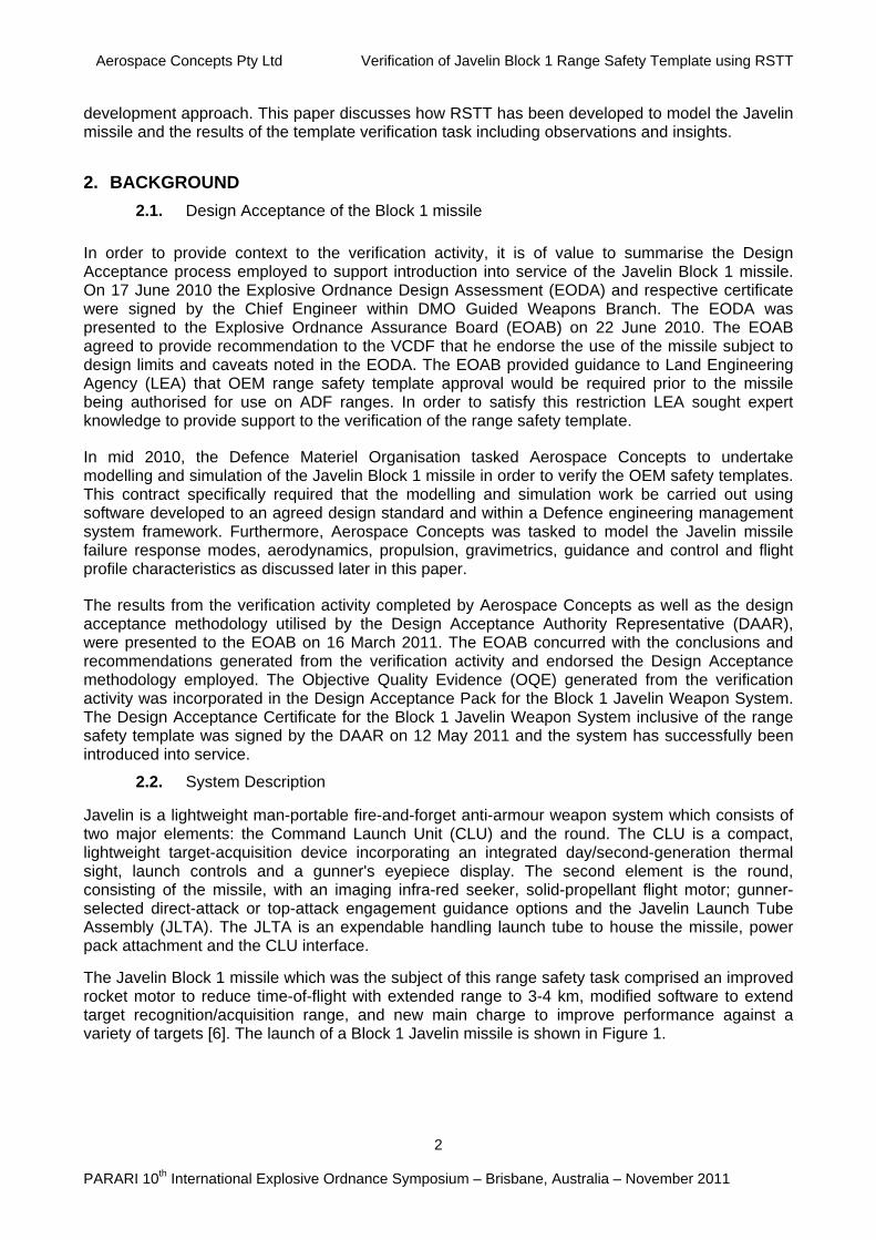
Javelin is a lightweight man-portable fire-and-forget anti-armour weapon system which consists of two major elements: the Command Launch Unit (CLU) and the round. The CLU is a compact, lightweight target-acquisition device incorporating an integrated day/second-generation thermal sight, launch controls and a gunner's eyepiece display. The second element is the round, consisting of the missile, with an imaging infra-red seeker, solid-propellant flight motor; gunner-selected direct-attack or top-attack engagement guidance options and the Javelin Launch Tube Assembly (JLTA). The JLTA is an expendable handling launch tube to house the missile, power pack attachment and the CLU interface.
The Javelin Block 1 missile which was the subject of this range safety task comprised an improved rocket motor to reduce time-of-flight with extended range to 3-4 km, modified software to extend target recognition/acquisition range, and new main charge to improve performance against a variety of targets [6]. The launch of a Block 1 Javelin missile is shown in Figure 1.
Aerospace Concepts Pty Ltd Verification of Javelin Block 1 Range Safety Template using RSTT
3
PARARI 10th International Explosive Ordnance Symposium – Brisbane, Australia – November 2011
Figure 1. Javelin Block 1 launch
3. RANGE SAFETY TEMPLATES
3.1. Introduction
Range safety templates, otherwise variously known as ‘safety templates’, ‘weapon danger areas’ (WDAs), ‘safety traces’ or ‘safety footprint areas’, are tools for the assessment and management of the risk associated with the operation of aerospace vehicles including the various forms of guided and unguided munitions, space launch vehicles and returning spacecraft. A range safety template is defined for a particular set of mission conditions.
3.2. Probabilistic versus Deterministic Templates
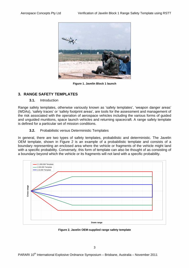
In general, there are two types of safety templates, probabilistic and deterministic. The Javelin OEM template, shown in Figure 2 is an example of a probabilistic template and consists of a boundary representing an enclosed area where the vehicle or fragments of the vehicle might land with a specific probability. Conversely, this form of template can also be thought of as consisting of a boundary beyond which the vehicle or its fragments will not land with a specific probability.
-1 5 0 0
-1 0 0 0
-5 0 0
0
5 0 0
1 0 0 0
1 5 0 0
0 5 0 0 1 0 0 0 1 5 0 0 2 0 0 0 2 5 0 0 3 0 0 0 3 5 0 0 4 0 0 0 4 5 0 0 5 0 0 0 5 5 0 0 6 0 0 0 6 5 0 0
Down range
Cro
ss r
ang
e
1:1,000,000 Template
1:100,000 Template
1:10,000 Template
Figure 2. Javelin OEM-supplied range safety template
Aerospace Concepts Pty Ltd Verification of Javelin Block 1 Range Safety Template using RSTT
4
PARARI 10th International Explosive Ordnance Symposium – Brisbane, Australia – November 2011
As can be seen from Figure 2, the Javelin OEM template is actually a nested set of templates, with the outer red boundary, for instance, representing a boundary beyond which Javelin or fragments of Javelin will only impact once in one million firings (1:1,000,000). This template would have been calculated from a Monte-Carlo simulation of Javelin nominal and failure behaviours with the final shape adjusted for ease of operational use, as shown above.
An alternative form of a probabilistic safety template takes the form of a contour plot representing different regions of ground impact probability or risks such as fatality or injury. For ease of operational use, the final shape of these contours are often adjusted as well, so if the Javelin OEM template was of this form the red boundary could represent the area within which the risk of fatality was greater than 1:1,000,000.
Probabilistic range safety templates are produced to satisfy defined criteria for what is acceptably safe. Probabilistic approaches are not new to Government and, indeed, concepts such as ‘As Low as Reasonably Practicable’ (ALARP) and associated criteria are already defined in Australian legislation1 and used to regulate potentially hazardous activities.
The other type of safety template is known as a deterministic template. In contrast to a probabilistic template, which is statistical in nature and has an explicit residual risk outside the template, a deterministic template will attempt to contain ‘100%’ of the risk by physically modelling the worst case scenario.
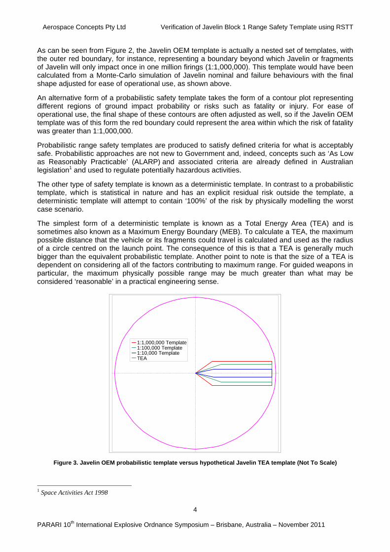
The simplest form of a deterministic template is known as a Total Energy Area (TEA) and is sometimes also known as a Maximum Energy Boundary (MEB). To calculate a TEA, the maximum possible distance that the vehicle or its fragments could travel is calculated and used as the radius of a circle centred on the launch point. The consequence of this is that a TEA is generally much bigger than the equivalent probabilistic template. Another point to note is that the size of a TEA is dependent on considering all of the factors contributing to maximum range. For guided weapons in particular, the maximum physically possible range may be much greater than what may be considered ‘reasonable’ in a practical engineering sense.
-6 5 0 0
-6 0 0 0
-5 5 0 0
-5 0 0 0
-4 5 0 0
-4 0 0 0
-3 5 0 0
-3 0 0 0
-2 5 0 0
-2 0 0 0
-1 5 0 0
-1 0 0 0
-5 0 0
0
5 0 0
1 0 0 0
1 5 0 0
2 0 0 0
2 5 0 0
3 0 0 0
3 5 0 0
4 0 0 0
4 5 0 0
5 0 0 0
5 5 0 0
6 0 0 0
6 5 0 0
-6 5 0 0 -6 0 0 0 -5 5 0 0 -5 0 0 0 -4 5 0 0 -4 0 0 0 -3 5 0 0 -3 0 0 0 -2 5 0 0 -2 0 0 0 -1 5 0 0 -1 0 0 0 -5 0 0 0 5 0 0 1 0 0 0 1 5 0 0 2 0 0 0 2 5 0 0 3 0 0 0 3 5 0 0 4 0 0 0 4 5 0 0 5 0 0 0 5 5 0 0 6 0 0 0 6 5 0 0
1:1,000,000 Template1:100,000 Template1:10,000 TemplateTEA
Figure 3. Javelin OEM probabilistic template versus hypothetical Javelin TEA template (Not To Scale)
1 Space Activities Act 1998
Aerospace Concepts Pty Ltd Verification of Javelin Block 1 Range Safety Template using RSTT
5
PARARI 10th International Explosive Ordnance Symposium – Brisbane, Australia – November 2011
Figure 3 is an illustration comparing the probabilistic Javelin OEM template to a hypothetical Javelin TEA. It should be noted that this figure is not to scale; its purpose is simply to illustrate the indicative relative sizes of probabilistic and deterministic templates.
4. RANGE SAFETY TEMPLATE GENERATION
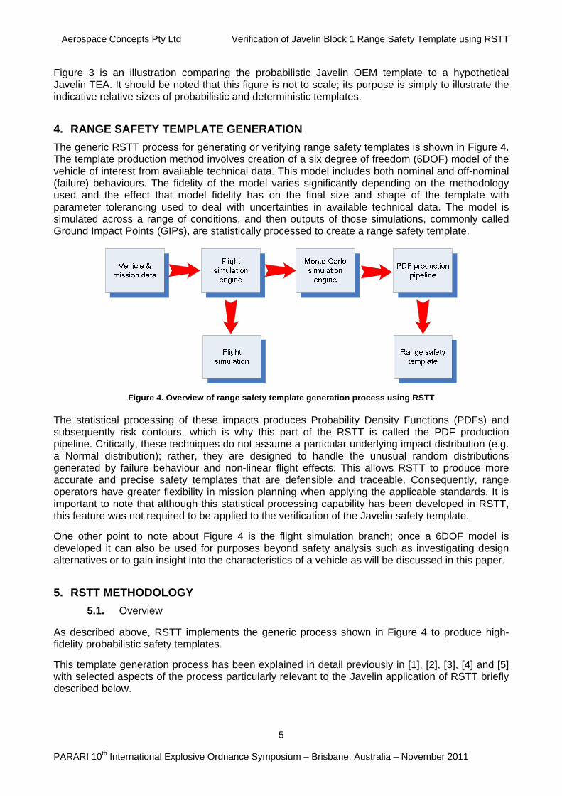
The generic RSTT process for generating or verifying range safety templates is shown in Figure 4. The template production method involves creation of a six degree of freedom (6DOF) model of the vehicle of interest from available technical data. This model includes both nominal and off-nominal (failure) behaviours. The fidelity of the model varies significantly depending on the methodology used and the effect that model fidelity has on the final size and shape of the template with parameter tolerancing used to deal with uncertainties in available technical data. The model is simulated across a range of conditions, and then outputs of those simulations, commonly called Ground Impact Points (GIPs), are statistically processed to create a range safety template.
Figure 4. Overview of range safety template generation process using RSTT
The statistical processing of these impacts produces Probability Density Functions (PDFs) and subsequently risk contours, which is why this part of the RSTT is called the PDF production pipeline. Critically, these techniques do not assume a particular underlying impact distribution (e.g. a Normal distribution); rather, they are designed to handle the unusual random distributions generated by failure behaviour and non-linear flight effects. This allows RSTT to produce more accurate and precise safety templates that are defensible and traceable. Consequently, range operators have greater flexibility in mission planning when applying the applicable standards. It is important to note that although this statistical processing capability has been developed in RSTT, this feature was not required to be applied to the verification of the Javelin safety template.
One other point to note about Figure 4 is the flight simulation branch; once a 6DOF model is developed it can also be used for purposes beyond safety analysis such as investigating design alternatives or to gain insight into the characteristics of a vehicle as will be discussed in this paper.
5. RSTT METHODOLOGY
5.1. Overview
As described above, RSTT implements the generic process shown in Figure 4 to produce high-fidelity probabilistic safety templates.
This template generation process has been explained in detail previously in [1], [2], [3], [4] and [5] with selected aspects of the process particularly relevant to the Javelin application of RSTT briefly described below.
Aerospace Concepts Pty Ltd Verification of Javelin Block 1 Range Safety Template using RSTT
6
PARARI 10th International Explosive Ordnance Symposium – Brisbane, Australia – November 2011
5.2. Missile Modelling
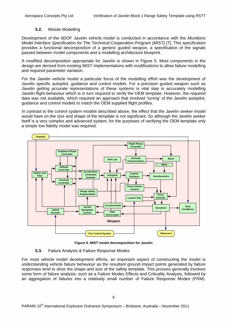
Development of the 6DOF Javelin vehicle model is conducted in accordance with the Munitions Model Interface Specification for The Technical Cooperation Program (MIST) [7]. This specification provides a functional decomposition of a generic guided weapon, a specification of the signals passed between model components and a modelling architecture blueprint.
A modified decomposition appropriate for Javelin is shown in Figure 5. Most components in the design are derived from existing MIST implementations with modifications to allow failure modelling and required parameter variation.
For the Javelin vehicle model a particular focus of the modelling effort was the development of Javelin specific autopilot, guidance and control models. For a precision guided weapon such as Javelin getting accurate representations of these systems is vital step in accurately modelling Javelin flight behaviour which is in turn required to verify the OEM template. However, the required data was not available, which required an approach that involved ‘tuning’ of the Javelin autopilot, guidance and control models to match the OEM supplied flight profiles.
In contrast to the control system models described above, the effect that the Javelin seeker model would have on the size and shape of the template is not significant. So although the Javelin seeker itself is a very complex and advanced system, for the purposes of verifying the OEM template only a simple low fidelity model was required.
Weapon
AutopilotControl
Surfaces
Force Summer
Rate Gyroscopes
Inertial Navigation
System
MotorAirframe Characteristics
Seeker and Filter
Roll Law
Wind
Thrust Vector Control
Uplink Decoder
Dynamics
Target(s)
Fire Control System Observers
Aerodynamics
Stop Conditions
Flight Phase Controller
Launch Rail
Range Safety Augmentation
Guidance Phase Controller
Terminal Controller
Accelerometer
Altitude Controller
Acceleration Command Summer
Figure 5. MIST model decomposition for Javelin
5.3. Failure Analysis & Failure Response Modes
For most vehicle model development efforts, an important aspect of constructing the model is understanding vehicle failure behaviour as the resultant ground impact points generated by failure responses tend to drive the shape and size of the safety template. This process generally involves some form of failure analysis, such as a Failure Modes Effects and Criticality Analysis, followed by an aggregation of failures into a relatively small number of Failure Response Modes (FRM).
Aerospace Concepts Pty Ltd Verification of Javelin Block 1 Range Safety Template using RSTT
7
PARARI 10th International Explosive Ordnance Symposium – Brisbane, Australia – November 2011
However, for this exercise the OEM supplied the FRMs and the interested reader is directed to [1], [2] and [3], where the process is described in greater detail.
5.4. Simulation
Following design and implementation of the 6DOF model with FRMs, the vehicle is simulated in a Monte Carlo environment to generate Ground Impact Point (GIP) distributions. Examples of such GIP distributions are shown in Figure 9 and Figure 10.
The modelling of appropriate parameter variation is a critical aspect of the RSTT simulation capability. For a missile system such as Javelin, the effects of parameters such as motor thrust misalignment, body mass variation, aerodynamic drag scaling and wind weighting error dispersions are simulated with the RSTT Monte Carlo engine. An important aspect of modelling guided missiles such as Javelin is ensuring that the guidance system can cope with these variations and dispersions.
5.5. Statistical Processing (PDF production pipeline)
The final part of the RSTT process involves the statistical processing of the GIPs (commonly several million) for all FRMs into Probability Density Functions and then into risk products such as casualty risk. However, the verification of the Javelin OEM template did not require this step and so the interested reader is directed to [8] for a description of the process details.
6. JAVELIN ANALYSIS METHODOLOGY AND RESULTS
6.1. Overview
This section presents the methodology and results of the Javelin missile fly-out simulations using RSTT, the validation of the nominal missile behaviour against OEM-provided flight profiles and comparisons of the nominal and FRM GIP sets against the OEM range safety template.
6.2. Methodology
A model of the Javelin missile was created within the RSTT simulation environment using data sourced from the technical data provided as described above. The missile nominal behaviour was validated against OEM provided trajectory plots and descriptions of behaviour as provided in the technical data. The model was then used to generate ground impacts points (GIPs) for a range of flight conditions and failure modes. Monte-Carlo methods were used to vary trajectory parameters to create GIP sets. The results of the simulations were then analysed to assess general correctness and reasonableness of the RSTT-generated results and then against the equivalent OEM range safety template.
Analysing the Top Attack mode of Javelin was emphasised throughout this analysis, and the OEM range safety template verification was performed solely for Top Attack. This approach was taken as the higher altitude profile used in Top Attack mode leads to a greater dispersion of GIPs a (nd therefore has a much greater significance to range safety concerns than the Direct Attack mode.
Also note that the verification effort focused on the ‘1 in a million’ safety template provided by the OEM. The alternative higher-risk templates for 1 in 100,000’ and ‘1 in 10,000’ were not analysed.
The analysis effort was guided by the following principles to provide confidence in the integrity of the analysis whilst managing resources expended:
Reuse of existing components and techniques. The model definition and simulation techniques were based directly on previous RSTT work.
Aerospace Concepts Pty Ltd Verification of Javelin Block 1 Range Safety Template using RSTT
8
PARARI 10th International Explosive Ordnance Symposium – Brisbane, Australia – November 2011
Modelling fidelity. Noting that the purpose of the analysis was verification of OEM safety template, modelling resources were expended primarily on missile behaviour that affects range safety, as described above. The model’s fidelity in other flight phases, such as during terminal guidance, was limited.
Adherence to engineering management requirements. All model development and simulation work was conducted in accordance with the requirements of the Defence-endorsed DSTO Engineering Management System.
Independent review for assurance. Independent peer review of the data, assumptions and associated analysis to independently verify the correctness or reasonableness of the data and techniques.
6.3. Model validation
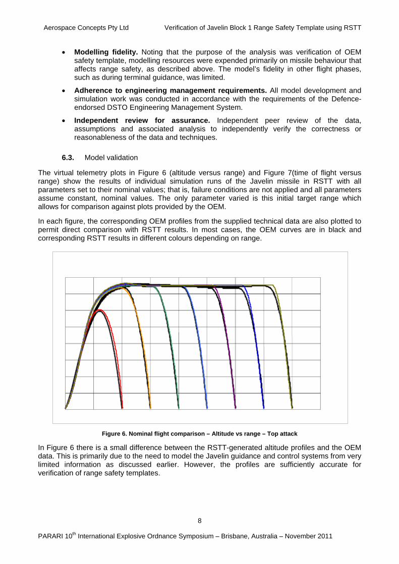
The virtual telemetry plots in Figure 6 (altitude versus range) and Figure 7(time of flight versus range) show the results of individual simulation runs of the Javelin missile in RSTT with all parameters set to their nominal values; that is, failure conditions are not applied and all parameters assume constant, nominal values. The only parameter varied is this initial target range which allows for comparison against plots provided by the OEM.
In each figure, the corresponding OEM profiles from the supplied technical data are also plotted to permit direct comparison with RSTT results. In most cases, the OEM curves are in black and corresponding RSTT results in different colours depending on range.
Figure 6. Nominal flight comparison – Altitude vs range – Top attack
In Figure 6 there is a small difference between the RSTT-generated altitude profiles and the OEM data. This is primarily due to the need to model the Javelin guidance and control systems from very limited information as discussed earlier. However, the profiles are sufficiently accurate for verification of range safety templates.
Aerospace Concepts Pty Ltd Verification of Javelin Block 1 Range Safety Template using RSTT
9
PARARI 10th International Explosive Ordnance Symposium – Brisbane, Australia – November 2011
Time of Flight vs Range - Top Attack
0
5
1 0
1 5
2 0
2 5
3 0
3 5
4 0
4 5
0 5 0 0 1 0 0 0 1 5 0 0 2 0 0 0 2 5 0 0 3 0 0 0 3 5 0 0 4 0 0 0 4 5 0 0
Range
Tim
e o
f F
ligh
t
RSTT
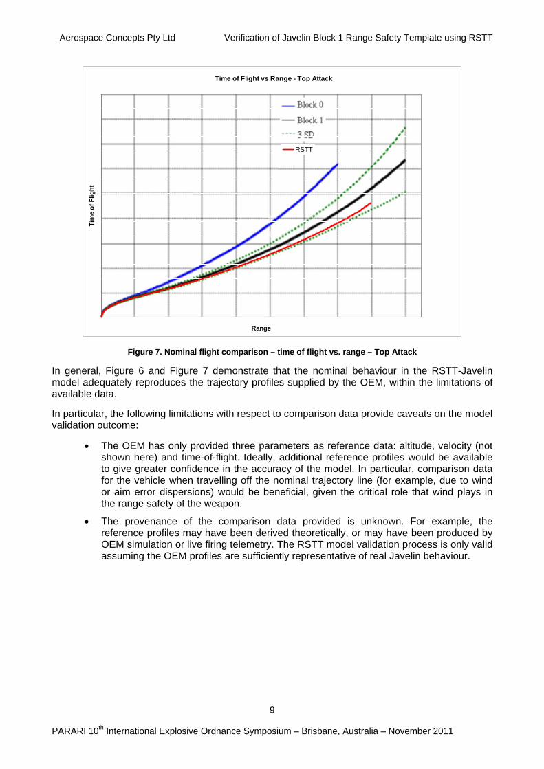
Figure 7. Nominal flight comparison – time of flight vs. range – Top Attack
In general, Figure 6 and Figure 7 demonstrate that the nominal behaviour in the RSTT-Javelin model adequately reproduces the trajectory profiles supplied by the OEM, within the limitations of available data.
In particular, the following limitations with respect to comparison data provide caveats on the model validation outcome:
The OEM has only provided three parameters as reference data: altitude, velocity (not shown here) and time-of-flight. Ideally, additional reference profiles would be available to give greater confidence in the accuracy of the model. In particular, comparison data for the vehicle when travelling off the nominal trajectory line (for example, due to wind or aim error dispersions) would be beneficial, given the critical role that wind plays in the range safety of the weapon.
The provenance of the comparison data provided is unknown. For example, the reference profiles may have been derived theoretically, or may have been produced by OEM simulation or live firing telemetry. The RSTT model validation process is only valid assuming the OEM profiles are sufficiently representative of real Javelin behaviour.
Aerospace Concepts Pty Ltd Verification of Javelin Block 1 Range Safety Template using RSTT
10
PARARI 10th International Explosive Ordnance Symposium – Brisbane, Australia – November 2011
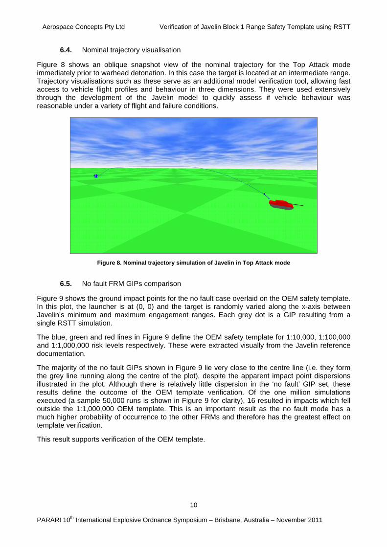
6.4. Nominal trajectory visualisation
Figure 8 shows an oblique snapshot view of the nominal trajectory for the Top Attack mode immediately prior to warhead detonation. In this case the target is located at an intermediate range. Trajectory visualisations such as these serve as an additional model verification tool, allowing fast access to vehicle flight profiles and behaviour in three dimensions. They were used extensively through the development of the Javelin model to quickly assess if vehicle behaviour was reasonable under a variety of flight and failure conditions.
Figure 8. Nominal trajectory simulation of Javelin in Top Attack mode
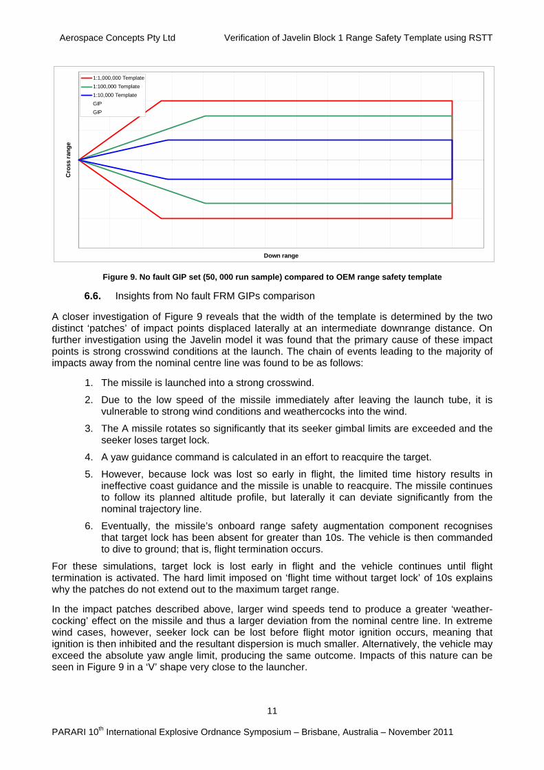
6.5. No fault FRM GIPs comparison
Figure 9 shows the ground impact points for the no fault case overlaid on the OEM safety template. In this plot, the launcher is at (0, 0) and the target is randomly varied along the x-axis between Javelin’s minimum and maximum engagement ranges. Each grey dot is a GIP resulting from a single RSTT simulation.
The blue, green and red lines in Figure 9 define the OEM safety template for 1:10,000, 1:100,000 and 1:1,000,000 risk levels respectively. These were extracted visually from the Javelin reference documentation.
The majority of the no fault GIPs shown in Figure 9 lie very close to the centre line (i.e. they form the grey line running along the centre of the plot), despite the apparent impact point dispersions illustrated in the plot. Although there is relatively little dispersion in the ‘no fault’ GIP set, these results define the outcome of the OEM template verification. Of the one million simulations executed (a sample 50,000 runs is shown in Figure 9 for clarity), 16 resulted in impacts which fell outside the 1:1,000,000 OEM template. This is an important result as the no fault mode has a much higher probability of occurrence to the other FRMs and therefore has the greatest effect on template verification.
This result supports verification of the OEM template.
Aerospace Concepts Pty Ltd Verification of Javelin Block 1 Range Safety Template using RSTT
11
PARARI 10th International Explosive Ordnance Symposium – Brisbane, Australia – November 2011
-1 5 0 0
-1 0 0 0
-5 0 0
0
5 0 0
1 0 0 0
1 5 0 0
0 5 0 0 1 0 0 0 1 5 0 0 2 0 0 0 2 5 0 0 3 0 0 0 3 5 0 0 4 0 0 0 4 5 0 0 5 0 0 0 5 5 0 0 6 0 0 0 6 5 0 0
Down range
Cro
ss r
ang
e
1:1,000,000 Template
1:100,000 Template
1:10,000 Template
GIP
GIP
Figure 9. No fault GIP set (50, 000 run sample) compared to OEM range safety template
6.6. Insights from No fault FRM GIPs comparison
A closer investigation of Figure 9 reveals that the width of the template is determined by the two distinct ‘patches’ of impact points displaced laterally at an intermediate downrange distance. On further investigation using the Javelin model it was found that the primary cause of these impact points is strong crosswind conditions at the launch. The chain of events leading to the majority of impacts away from the nominal centre line was found to be as follows:
1. The missile is launched into a strong crosswind.
2. Due to the low speed of the missile immediately after leaving the launch tube, it is vulnerable to strong wind conditions and weathercocks into the wind.
3. The A missile rotates so significantly that its seeker gimbal limits are exceeded and the seeker loses target lock.
4. A yaw guidance command is calculated in an effort to reacquire the target.
5. However, because lock was lost so early in flight, the limited time history results in ineffective coast guidance and the missile is unable to reacquire. The missile continues to follow its planned altitude profile, but laterally it can deviate significantly from the nominal trajectory line.
6. Eventually, the missile’s onboard range safety augmentation component recognises that target lock has been absent for greater than 10s. The vehicle is then commanded to dive to ground; that is, flight termination occurs.
For these simulations, target lock is lost early in flight and the vehicle continues until flight termination is activated. The hard limit imposed on ‘flight time without target lock’ of 10s explains why the patches do not extend out to the maximum target range.
In the impact patches described above, larger wind speeds tend to produce a greater ‘weather-cocking’ effect on the missile and thus a larger deviation from the nominal centre line. In extreme wind cases, however, seeker lock can be lost before flight motor ignition occurs, meaning that ignition is then inhibited and the resultant dispersion is much smaller. Alternatively, the vehicle may exceed the absolute yaw angle limit, producing the same outcome. Impacts of this nature can be seen in Figure 9 in a ‘V’ shape very close to the launcher.
Aerospace Concepts Pty Ltd Verification of Javelin Block 1 Range Safety Template using RSTT
12
PARARI 10th International Explosive Ordnance Symposium – Brisbane, Australia – November 2011
The gap between the absolute vehicle azimuth limit and the seeker’s limited azimuth field-of-view suggests that this behaviour is both plausible and realistic if firing occurs in high winds. In fact, the phenomenon has been confirmed in the real system: the Javelin Joint Venture (JJV) reported at the 2nd Annual Javelin JSIC Conference in Nov 2009 that ‘crosswind hurts Javelin the most; with the wind speed specification consistent with the RSTT modelling and simulation reported here.
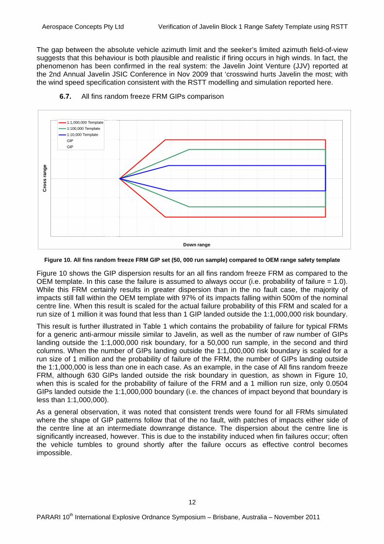
6.7. All fins random freeze FRM GIPs comparison
-1500
-1000
-500
0
500
1000
1500
-2 0 0 0 -1 5 0 0 -1 0 0 0 -5 0 0 0 5 0 0 1 0 0 0 1 5 0 0 2 0 0 0 2 5 0 0 3 0 0 0 3 5 0 0 4 0 0 0 4 5 0 0 5 0 0 0 5 5 0 0 6 0 0 0 6 5 0 0
Down range
Cro
ss
ra
ng
e
1:1,000,000 Template
1:100,000 Template
1:10,000 Template
GIP
GIP
Figure 10. All fins random freeze FRM GIP set (50, 000 run sample) compared to OEM range safety template
Figure 10 shows the GIP dispersion results for an all fins random freeze FRM as compared to the OEM template. In this case the failure is assumed to always occur (i.e. probability of failure = 1.0). While this FRM certainly results in greater dispersion than in the no fault case, the majority of impacts still fall within the OEM template with 97% of its impacts falling within 500m of the nominal centre line. When this result is scaled for the actual failure probability of this FRM and scaled for a run size of 1 million it was found that less than 1 GIP landed outside the 1:1,000,000 risk boundary.
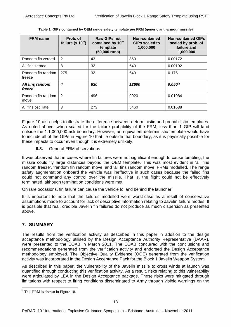
This result is further illustrated in Table 1 which contains the probability of failure for typical FRMs for a generic anti-armour missile similar to Javelin, as well as the number of raw number of GIPs landing outside the 1:1,000,000 risk boundary, for a 50,000 run sample, in the second and third columns. When the number of GIPs landing outside the 1:1,000,000 risk boundary is scaled for a run size of 1 million and the probability of failure of the FRM, the number of GIPs landing outside the 1:1,000,000 is less than one in each case. As an example, in the case of All fins random freeze FRM, although 630 GIPs landed outside the risk boundary in question, as shown in Figure 10, when this is scaled for the probability of failure of the FRM and a 1 million run size, only 0.0504 GIPs landed outside the 1:1,000,000 boundary (i.e. the chances of impact beyond that boundary is less than 1:1,000,000).
As a general observation, it was noted that consistent trends were found for all FRMs simulated where the shape of GIP patterns follow that of the no fault, with patches of impacts either side of the centre line at an intermediate downrange distance. The dispersion about the centre line is significantly increased, however. This is due to the instability induced when fin failures occur; often the vehicle tumbles to ground shortly after the failure occurs as effective control becomes impossible.
Aerospace Concepts Pty Ltd Verification of Javelin Block 1 Range Safety Template using RSTT
13
PARARI 10th International Explosive Ordnance Symposium – Brisbane, Australia – November 2011
Table 1. GIPs contained by OEM range safety template per FRM (generic anti-armour missile)
FRM name Prob. of failure (x 10-6)
Raw GIPs not contained by 10-6
template (50,000 runs)
Non-contained GIPs scaled to
1,000,000
Non-contained GIPs scaled by prob. of
failure and 1,000,000
Random fin zeroed 2 43 860 0.00172
All fins zeroed 3 32 640 0.00192
Random fin random freeze
275 32 640 0.176
All fins random freeze2
4 630 12600 0.0504
Random fin random move
2 496 9920 0.01984
All fins oscillate 3 273 5460 0.01638
Figure 10 also helps to illustrate the difference between deterministic and probabilistic templates. As noted above, when scaled for the failure probability of the FRM, less than 1 GIP will land outside the 1:1,000,000 risk boundary. However, an equivalent deterministic template would have to include all of the GIPs in Figure 10 that lie outside that boundary, as it is physically possible for these impacts to occur even though it is extremely unlikely.
6.8. General FRM observations
It was observed that in cases where fin failures were not significant enough to cause tumbling, the missile could fly large distances beyond the OEM template. This was most evident in ‘all fins random freeze’, ‘random fin random move’ and ‘all fins random move’ FRMs modelled. The range safety augmentation onboard the vehicle was ineffective in such cases because the failed fins could not command any control over the missile. That is, the flight could not be effectively terminated, although termination conditions were met.
On rare occasions, fin failure can cause the vehicle to land behind the launcher.
It is important to note that the failures modelled were worst-case as a result of conservative assumptions made to account for lack of descriptive information relating to Javelin failure modes. It is possible that real, credible Javelin fin failures do not produce as much dispersion as presented above.
7. SUMMARY
The results from the verification activity as described in this paper in addition to the design acceptance methodology utilised by the Design Acceptance Authority Representative (DAAR), were presented to the EOAB in March 2011. The EOAB concurred with the conclusions and recommendations generated from the verification activity and endorsed the Design Acceptance methodology employed. The Objective Quality Evidence (OQE) generated from the verification activity was incorporated in the Design Acceptance Pack for the Block 1 Javelin Weapon System.
As described in this paper, the vulnerability of the Javelin missile to cross winds at launch was quantified through conducting this verification activity. As a result, risks relating to this vulnerability were articulated by LEA in the Design Acceptance package. These risks were mitigated through limitations with respect to firing conditions disseminated to Army through visible warnings on the
2 This FRM is shown in Figure 10.
Aerospace Concepts Pty Ltd Verification of Javelin Block 1 Range Safety Template using RSTT
14
PARARI 10th International Explosive Ordnance Symposium – Brisbane, Australia – November 2011
endorsed range safety template. The Design Acceptance Certificate for the Block 1 Javelin Weapon System inclusive of the range safety template was signed by the DAAR on 12 May 2011 and the system has since been successfully introduced into service.
8. CONCLUSIONS
This application of the RSTT, which integrates the high-fidelity aerospace vehicle modeling with Monte-Carlo simulation, demonstrates how such a tool can be used to support Design Acceptance when OEM data is missing or to increase confidence in the veracity of the OEM data (in this case the Range Safety Template).
Furthermore, a weapon model developed within a suitable Engineering Management System, and then accepted as being a reasonable representation of the weapon, can be used for a range of purposes including performance characterisation, tactics development and the assessment of upgrades and changes to the weapon over the lifecycle.
9. ACKNOWLEDGEMENTS
The authors wish to thank the Defence Materiel Organisation (DMO) for their permission to publish this work and the Defence Science and Technology Organisation (DSTO) for their assistance and for supporting specific aspects of the autopilot modelling.
10. REFERENCES
1. Wilson, S.A., Vuletich, I.J., Bryce I.R., Brett, M.S., Williams, W.R., Fletcher, D.J., Jokic, M.D. & Cooper, N. (2009).
Space Launch & Re-entry Risk Hazard Analysis – A New Capability, 60th International Astronautical Congress (IAC), Daejeon, Korea.
2. Wilson, S.A., Vuletich, I.J., Fletcher, D.J., Jokic, M.D., Brett, M.S., Boyd, C.S., Williams, W.R. & Bryce, I.R. (2008). Guided Weapon Danger Area & Safety Template Generation – A New Capability, AIAA Atmospheric Flight Mechanics Conference, Honolulu, Hawaii, USA.
3. Fletcher, D.J., Wilson, S.A., Jokic, M.D. & Vuletich, I.J. (2006). Guided Weapon Safety Trace Generation – Implementing a Probabilistic Approach, AIAA Atmospheric Flight Mechanics Conference, Keystone, Colorado, USA.
4. Jokic, M.D, White, T., Fletcher, D.J., Wilson, S.A. & Vuletich, I.J. (2007). Guided Weapon Danger Area Generation – Australian Capability Development, International Range Safety Advisory Group, Amsterdam, The Netherlands.
5. Fletcher, D.J., Jokic, M.D. & Graham, R.F. (2007). DSTO Approach to Standoff Weapon Danger Area Generation, International Range Safety Advisory Group, Amsterdam, The Netherlands.
6. Janes Infantry Weapons online, IHS Jane’s, viewed 28 August 2011, < http://search.janes.com>
7. Fletcher, D.J. et al. (2006). MIST Interface Specification Version 1.0, TR-WPN-7/1-2006, The Technical Cooperation Program, Edinburgh, Australia.
8. Staniford, T., Glonek, G. & Rumsewicz, M. (2006). Investigation of Appropriate Size of Datasets, Resolution of Kernel Density Estimates and the Generation of Kernel Density Estimates Between Input Scenarios Using Interpolation, Adstat Solutions, Adelaide, Australia.