Computed tomographic imaging in endodontics a short literatue review

Washington University School of MedicineDigital Commons@Becker
Independent Studies and Capstones Program in Audiology and CommunicationSciences
2010
Verification of computed tomographic estimates ofcochlear implant array position: A micro-CT andhistological analysisJessica Teymouri
Follow this and additional works at: http://digitalcommons.wustl.edu/pacs_capstones
Part of the Medicine and Health Sciences Commons
This Thesis is brought to you for free and open access by the Program in Audiology and Communication Sciences at Digital Commons@Becker. It hasbeen accepted for inclusion in Independent Studies and Capstones by an authorized administrator of Digital Commons@Becker. For moreinformation, please contact [email protected].
Recommended CitationTeymouri, Jessica, "Verification of computed tomographic estimates of cochlear implant array position: A micro-CT and histologicalanalysis" (2010). Independent Studies and Capstones. Paper 593. Program in Audiology and Communication Sciences, WashingtonUniversity School of Medicine.http://digitalcommons.wustl.edu/pacs_capstones/593

VERIFICATION OF COMPUTED TOMOGRAPHIC ESTIMATES OF COCHLEAR IMPLANT ARRAY POSITION: A MICRO-CT AND
HISTOLOGICAL ANALYSIS
by
Jessica Teymouri
A Capstone Project submitted in partial fulfillment of the
requirements for the degree of:
Doctor of Audiology
Washington University School of Medicine Program in Audiology and Communication Sciences
May 20, 2011
Approved by:
Richard Chole, M.D., Ph.D. Capstone Project Advisor Timothy Hullar, M.D., FACS, Second Reader
Abstract: We examine the efficacy two volume spatial registration of pre and post-operative clinical computed tomography (CT) imaging to verify post-operative electrode array placement in cochlear implant (CI) patients. To measure the degree of accuracy with which the composite image predicts in-vivo placement of the array, we replicate the CI surgical process in cadaver heads. Pre-operative, post-operative, micro CT imaging and histology are utilized for verification.

copyright by
Jessica R. Teymouri
2011

Teymouri
ii
Acknowledgements: I would like to thank the following people for their support and guidance in the completion of
this project:
Richard Chole, M.D., Ph.D., Capstone Project Advisor Timothy Hullar, M.D., FACS, Second Reader
Timothy Holden, B.S.E. Patricia Keller, Histology Core Manager
Human donors
This capstone project was supported by:
Department of Otolaryngology WUSM (Chole 2R01DC 000263-22)
(Hullar K08)

Teymouri
1
TABLE OF CONTENTS
Acknowledgments…………………………………………………………………………...(ii)
Table of Contents……………………………………………………………............................(1)
List of Tables and Figures……………………………………………………………...….…...(2)
Abbreviations………………………………………………………………………………......(3)
Background……………………………………………………………………………….…....(4)
Methods………………………………………………………………………………………(15)
Results…………………………………………………………………………………….......(19)
Discussion……………………………………………………………………………………..(27)
Conclusion…………………………………………………………………………………….(28)
References…………………………………………………………………………………….(29)

Teymouri
2
LIST OF TABLES & FIGURES
FIGURE 1: Reviewer’s form……………………………………………........(18)
FIGURES 2-4: Computed tomography images……………………………...........(20)
FIGURES 5-6: Midmodiolar section and close view……………………………..(23)
FIGURES 7-8: Example of swelling artifact……………………………………(24-25)
FIGURE 9: Three-dimensional rendering of cochlea with array…..................(25)
FIGURES 10-12: CT and histology images………………………………………...(26)
TABLES 1-6: Histology and CT technique correlation……………………….(21-23)

Teymouri
3
ABBREVIATIONS
2D Two dimensional
3D Three dimensional
AOS Advance off stylet
CI Cochlear implant
CNC Consonant-nucelus-consonant
CT Computed tomography
EAS Electro-acoustic stimulation
HINT Hearing in noise test
MMA Methamethacrylate
OPFOS Orthogonal-plane fluorescence optical sectioning
RW Round window
SIT Standard insertion technique
SM Scala media
SPEAK Spectral peak processing strategy
ST Scala tympani
SV Scala vestibuli

Teymouri
4
Introduction
Since the inception of the multichannel cochlear implant (CI), numerous factors have
been identified that affect clinical outcomes and performance. One of those factors is variation
of surgical technique and the resultant position of the electrode array. As a result, advancements
have been made in electrode design and surgical techniques. Refinements of surgical techniques
must be accompanied by refinements in objective, reliable clinical measures to verify that goals
of the surgery have been realized. Clinical computed tomography (CT) scanning is one such
applicable tool. In 2002, Skinner et al. described four main approaches to estimating the in vivo
intra-cochlear position of the implanted electrode array, the first of which is the surgeon’s report.
The remaining methods are based on image analysis. Skinner, et al. (2002) created a technique
utilizing spatial registration of a CI patient’s pre and post-operative CT scans aligned with a
cochlear atlas that defines intra-cochlear structure. The atlas is based on orthogonal-plane
fluorescence optical sectioning (OPFOS) microscopy scan of a single, normal hearing donor
(Voie, 2002). OPFOS is an imaging technique that yields quantitative measurements of the
mammalian cochlea and facilitates three dimensional (3D) reconstructions of its intricate
anatomy. The 3-D image that is derived from the CT volume registration is used to estimate
medio-lateral and scalar position, and depth of insertion of the electrode array. Research
suggests these variables are not only related to preservation of residual hearing, but may
influence performance outcomes (Skinner, 2007; Finley, 2008).
The technique developed by Skinner, et al. (2007) addresses the issue of “bloom” artifact
from the metal contacts in the array, which obscures visualization in the post-operative scan.
Metallic electrodes in the array are identified and refined using a pixel threshold technique in
ANALYZE® software (Robb, et al. 1989). The resulting image is then translated to the

Teymouri
5
preoperative CT volume. Identification of scalar boundaries presents a challenge due to the
limited spatial resolution and soft tissue detail available with clinical CT which images
bone/tissue boundaries. This is addressed by overlaying the cochlear atlas onto the combined CT
data to better visualize the scalar position of the CI array. However, only an approximation of
the scalar divisions is available and there is no information as to how the implanted array is
interacting with the intra-cochlear soft tissue structures. The aim of this study is to address these
perceived limitations by replicating the clinical CI surgical process using non-fixed cadaver
heads. Outcomes are verified using pre and post-operative CT scanning, as well as micro CT
(Lane, et al. 2007) scanning and a histological analysis that serves as the gold standard.
Background
Conservation of cochlear anatomy and preservation of residual hearing have implications
for traditional CI candidates, candidates for bimodal hearing, and future treatment options for
cochlear implant recipients (Gantz, 2005; Balkany, 2006; Fraysse 2006; James, 2005; James,
2006). Patients with greater residual hearing also benefit from lower thresholds of stimulation,
which are determined during device programming. This decreases power consumption of the
external portion of the device. Maximization of surviving neural elements may also allow for
finer frequency perception (Roland, 2005). Furthermore, CI recipients who have higher numbers
of electrodes residing in the scala tympani (ST) and less insertion trauma obtain greater benefit
from the device (Skinner, 2002; Aschendorff, 2007), as evidenced by their higher scores on open
set word recognition testing.
Unlike other factors affecting clinical outcomes such as etiology, length of auditory
deprivation or surviving spiral ganglion cells, surgical placement of the electrode array is one

Teymouri
6
variable over which the surgeon may exert a considerable amount of control. Numerous studies
demonstrate that by implementing an atraumatic, or soft surgical technique, patient outcomes
may be positively affected due to the greatest number of electrodes inserted into and remaining
in ST, a decrease in damage to the organ of Corti, and the greatest opportunity for preservation
of residual hearing.
Atraumatic Surgery
It was once accepted that after cochlear implant surgery, the only transmission route of
sound to the auditory nerve would be through electrical stimulation via the implant, as insertion
trauma during the surgical process would destroy all residual hearing (Copeland, 2004).
However, recent studies and clinical trials have demonstrated the feasibility of hearing
preservation following cochlear implantation in conjunction with refined surgical approach.
“Soft surgery” is a term used to describe surgical implantation of the electrode array that
results in the least amount of disruption and damage to cochlear structures such as the basilar
membrane, osseous spiral lamina, and the modiolar wall. Atraumatic insertions decrease sequela
secondary to fibrosis and ossification after placement of the array (Berrettini, 2007).
Components of the technique include: anterior-inferior cochleostomy placement with respect to
the round window (Balkany, 2006), cochleostomy size less than 1.2 mm, placement of the array
in the ST, avoidance of suction of perilymphatic fluid, containment of bone dust (Lehnhardt,
1994; Friedland, 2009), a slow rate of insertion (Roland, 2005), as well as an insertion depth of
less than 400 degrees (Fraysse et al., 2005).
Increased rates of conservation of residual hearing, in conjunction with improved surgical
technique and CI technology have been reported (Gantz, 2005; Fraysse, 2006). For example,
Teymouri
7
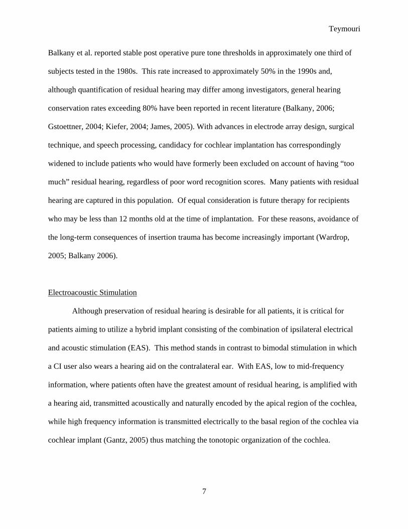
Balkany et al. reported stable post operative pure tone thresholds in approximately one third of
subjects tested in the 1980s. This rate increased to approximately 50% in the 1990s and,
although quantification of residual hearing may differ among investigators, general hearing
conservation rates exceeding 80% have been reported in recent literature (Balkany, 2006;
Gstoettner, 2004; Kiefer, 2004; James, 2005). With advances in electrode array design, surgical
technique, and speech processing, candidacy for cochlear implantation has correspondingly
widened to include patients who would have formerly been excluded on account of having “too
much” residual hearing, regardless of poor word recognition scores. Many patients with residual
hearing are captured in this population. Of equal consideration is future therapy for recipients
who may be less than 12 months old at the time of implantation. For these reasons, avoidance of
the long-term consequences of insertion trauma has become increasingly important (Wardrop,
2005; Balkany 2006).
Electroacoustic Stimulation
Although preservation of residual hearing is desirable for all patients, it is critical for
patients aiming to utilize a hybrid implant consisting of the combination of ipsilateral electrical
and acoustic stimulation (EAS). This method stands in contrast to bimodal stimulation in which
a CI user also wears a hearing aid on the contralateral ear. With EAS, low to mid-frequency
information, where patients often have the greatest amount of residual hearing, is amplified with
a hearing aid, transmitted acoustically and naturally encoded by the apical region of the cochlea,
while high frequency information is transmitted electrically to the basal region of the cochlea via
cochlear implant (Gantz, 2005) thus matching the tonotopic organization of the cochlea.

Teymouri
8
The combination of electrical and acoustic information plays a critical role in speech
recognition in the presence of noise for some CI users (James, et al., 2006). Fraysse, et al.
(2006), James (2005) and Gantz (2005) found that signal to noise ratios for speech recognition in
multi-talker babble increased by 3-9 dB in the CI + ipsilateral hearing aid as compared to the CI
alone condition. This translates to 30-40% increase in speech understanding as demonstrated by
Eddington, et al. using the hearing in noise test (HINT) (House Ear Institute) sentence scores
(1997). Moreover, CI users subjectively prefer the quality of sound with EAS. Those patients
with a post-lingual onset of hearing loss often describe speech with a CI as sounding synthetic,
mechanical, or “raspy.” This complaint is likely due to the limited spectral resolution (the
inability to reproduce the range of pitch perception present in normal hearing) available using a
CI. Although limited pitch perception may not interfere with speech understanding in quiet, it is
detrimental to the user when listening to speech in the presence of background noise which
requires more acute pitch discrimination (Gantz, 2005).
Subjective improvement in the aesthetic quality of sound (James, 2006) using EAS is also
encouraging as it relates to music appreciation with a CI. Gantz et al. (2005) found that EAS
users were substantially more accurate than traditional CI users in melody recognition, pure tone
frequency discrimination, as well as timbre ratings for low frequencies. In addition, the mean
score for EAS users in an open-set test of familiar melody recognition was 80.1% correct (1 year
post hook-up) as compared to the mean score for 27 traditional CI users of 30.7%. Ability to
perceive the fundamental frequency via residual acoustic hearing may account for the difference
in scores and in the ability to enjoy both familiar and novel music.

Teymouri
9
Scala Tympani Placement
Real world benefit and preservation of cochlear structures are optimized placement of the
electrode array into the ST. Physiologically, insertion into the ST places the electrode contacts
in close proximity to excitable neurons of interest; those in the osseous spiral lamina and the
ganglion cells within Rosenthal’s canal. Also, the ST is bounded by both the basilar membrane
and osseous spiral lamina, offering a natural protective mechanism during insertion, while the
scala vestibuli (SV) and the scala media (SM) are separated only by Reissner’s membrane, a
fragile two-celled layered structure. The significance of this may be appreciated when
considering that even minor intracochlear trauma to the osseous spiral lamina during insertion
has been shown to correlate with increased thresholds and a decrease in response selectivity
(Wardrop, 2005). Finally, the lumen of the ST has a slightly larger diameter than that of the SV
for increased accommodation of the array.
Clinically, word recognition may also be affected by array placement. Studies have
suggested that insertion, or migration, of the array from the ST into the SV may be detrimental to
speech comprehension. Skinner, et al. (2002) observed a significant negative correlation
between consonant-nucleus-consonant (CNC) (Lehiste & Peterson, 1959) word scores and the
number of electrodes in SV, as verified by pre- and post-operative CT images registered three
dimensionally. Conversely, the highest scoring subjects had the greatest number of electrodes in
the ST. Skinner stated, “This finding suggests that when electrodes are not in their intended
position in the ST, their stimulation of surviving nerve fibers is associated with poorer word
recognition than might have been possible if they had been in ST.” Similarly, in 2008 Finley, et
al. deduced that a significant portion of outcome variance in user performance on CNC word
recognition was attributable to scalar position of the electrode array. When an electrode contact

Teymouri
10
lies in the SV, rather than the ST, the likelihood of cross-turn stimulation is increased. In this
scenario, a contact lying equidistant between spiral ganglion neurons located at ascending turns
within the cochlea, when stimulated, would excite ganglion cells at various critical bandwidths
(Greenwood 1961), creating perceptual pitch cues that are confusing for the user (Finley, 2008).
In Finley’s 2008 study, statistical analysis revealed that a significant estimated improvement in
CNC word recognition scores could be obtained with optimized scalar placement of the array in
the ST.
Cochleostomy
A cochleostomy located adjacent to the anterior-inferior portion of the round window
(RW) decreases the risk of inadvertent entry into the SM or the SV (Lenhardt, 2009), and sets the
stage for subsequent surgical outcomes such as placement in the ST and preservation of the
lateral wall and osseous spiral lamina (Finley 2008). Studies comparing locations have found
that the highest rates of residual hearing preservation correspond to cochleostomy placement
anterior-inferior to the RW, as opposed to entry through, or inferior to, the RW (Garcia-Ibanez,
et al., 2008; Berrettini, 2008; Adunka, et al., 2007; Gantz, 2005). Finley, et al. (2008) observed
in a group of fourteen subjects that in cases where the majority of contacts were located in SV, as
verified by CT scan, that cochleostomy sites appeared to have been made too high along the
lateral cochlear wall. They noted, “…cochleostomy placement antero-inferior to the RW
annulus appears critical to consistent and desired placement in ST….”

Teymouri
11
Insertion Force
Components of force acting on the outer wall of the cochlea during array insertion
include tension introduced by the surgeon, frictional force, relaxation force of the array, and
adhesion forces (Todd, 2007). Combined, these forces exert pressure on the spiral ligament and
in excess, may cause trauma. Implant manufacturers have attempted to remediate this issue in
electrode array design and insertion techniques. For example, the “advance off stylet” (AOS)
(Cochlear Corporation®, Sydney, Australia) is a technique in which the Nucleus 24 Contour
Advance® electrode array is held in a straight position by an internal wire during insertion, until
the point at which a white marker on the carrier site is aligned with the cochleostomy. The stylet
is held in place while the array is advanced to its final intracochlear position where it resumes its
preformed shape around the modiolus (Roland, 2005; Wardrop, 2005). In contrast, when the
standard insertion technique (SIT), or partial withdrawal method, is performed with the Nucleus
24 Contour® the array is advanced into the cochlea while the stylet is held in place and
withdrawn after full insertion (Todd, 2007). In 2005 Roland, et al. employed an Instron 5543
Universal Force Measurement System to quantify the force exerted on the intracochlear outer
wall during CI electrode array insertion using both techniques. The measurements were made in
cochlear models, and in formalin-fixed cadaveric temporal bones. Insertions using the AOS
technique were made with fewer points of contact with the outer wall and significantly less force.
Results were similar to those reported in other studies (Berettini, 2008; Todd, 2007; Stover,
2005). In their comparison of AOS and SIT, Todd, et al. (2007) noted a marked reduction in
force application using the AOS technique, particularly at the basal turn, which historically has
been the most vulnerable to insertion trauma (Biedron, 2010). They attributed the more desirable

Teymouri
12
outcome to a combination of improved trajectory along the medial wall of the ST and an overall
reduction in rigidity of the electrode.
Insertion Depth
Linear and angular insertion depth of the electrode array insertion have been suggested as
variables that may correlate with hearing preservation and word recognition using a CI (Adunka,
2006; Gani, 2006; Finley, 2008). Therefore, a delicate balance between sufficient stimulation
and conservation of cochlear structures must be struck. Linear insertion depth is length of
insertion of the array in millimeters, and angular insertion depth represents degrees of rotation
from a reference point, for example, the RW, vestibule or other anatomical landmark. Both may
vary due to individual cochlear dimensions, and type of electrode array (Radeloff, 2008; Escude,
2006). However, some general guidelines have emerged. For example, advancing the array past
the point of first resistance, which generally occurs between 17- 20 mm (Adunka, 2006) may
cause rupture of the basilar membrane, fracture of the osseous spiral lamina and/or ligament, and
buckling of the array (Adunka, 2006; James, 2005; Wardrop, 2005).
Over insertion of the array (past the point of first resistance) may result in insufficient
stimulation of the basal region due to a void in electrodes. This results in diminished high
frequency cues needed for speech understanding. Meanwhile, the risk of mechanical trauma
increases with depth of insertion due to the anatomy of the cochlea and its limited ability to
accommodate force as the radius of curvature increases and canal cross section area decreases as
the apex is approached. Using human temporal bones Adunka et al. (2006) witnessed a positive
relationship between insertion depth and cochlear trauma, particularly when the array was
advanced past the point of first resistance which was, on average, reached at 20 mm.
Teymouri
13
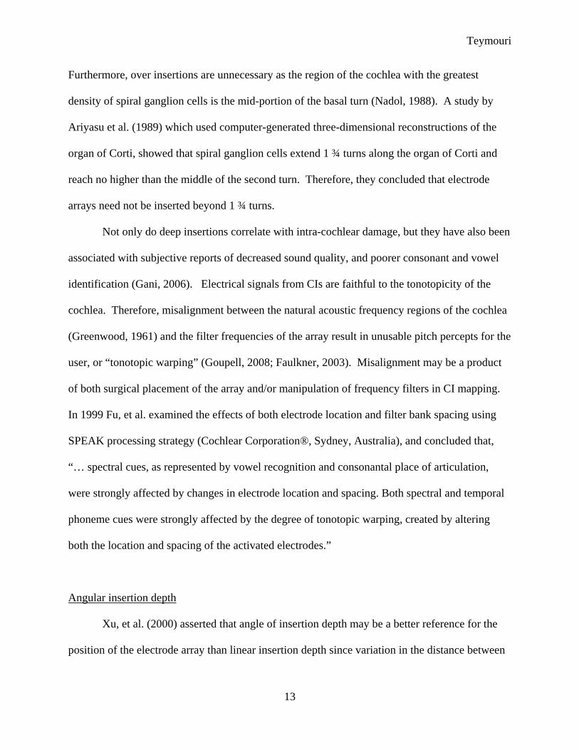
Furthermore, over insertions are unnecessary as the region of the cochlea with the greatest
density of spiral ganglion cells is the mid-portion of the basal turn (Nadol, 1988). A study by
Ariyasu et al. (1989) which used computer-generated three-dimensional reconstructions of the
organ of Corti, showed that spiral ganglion cells extend 1 ¾ turns along the organ of Corti and
reach no higher than the middle of the second turn. Therefore, they concluded that electrode
arrays need not be inserted beyond 1 ¾ turns.
Not only do deep insertions correlate with intra-cochlear damage, but they have also been
associated with subjective reports of decreased sound quality, and poorer consonant and vowel
identification (Gani, 2006). Electrical signals from CIs are faithful to the tonotopicity of the
cochlea. Therefore, misalignment between the natural acoustic frequency regions of the cochlea
(Greenwood, 1961) and the filter frequencies of the array result in unusable pitch percepts for the
user, or “tonotopic warping” (Goupell, 2008; Faulkner, 2003). Misalignment may be a product
of both surgical placement of the array and/or manipulation of frequency filters in CI mapping.
In 1999 Fu, et al. examined the effects of both electrode location and filter bank spacing using
SPEAK processing strategy (Cochlear Corporation®, Sydney, Australia), and concluded that,
“… spectral cues, as represented by vowel recognition and consonantal place of articulation,
were strongly affected by changes in electrode location and spacing. Both spectral and temporal
phoneme cues were strongly affected by the degree of tonotopic warping, created by altering
both the location and spacing of the activated electrodes.”
Angular insertion depth
Xu, et al. (2000) asserted that angle of insertion depth may be a better reference for the
position of the electrode array than linear insertion depth since variation in the distance between

Teymouri
14
the modiolus and the array is not a factor in the former metric. Similar to linear insertion depth,
there appears to be a negative correlation between increased angular insertion depth and patient
outcomes. Both James et al. (2005) and Fraysse et al. (2006) demonstrated that insertion depth
angles exceeding 400° resulted in poorer preservation of residual hearing. Finley et al. (2008)
found that angular insertion depths of select basal electrodes were significantly related to an
increase in the number of electrodes migrating to SV, the demerits of which are aforementioned.
In 2006 Kos et al. reported the results of the withdrawal of electrode arrays that were
deeply inserted in two patients with subjective reports of poor sound quality due to excessive low
pitch sound, echoes, and poor word discrimination, despite sufficient adaptation time and fine
tuning of their maps. After partial withdrawal of arrays, insertion angles decreased from 720° to
485° for one patient and from 675° to 433° for the second patient. Following partial withdrawal,
word recognition scores improved for both patients, as did the subjective quality of sound. Both
patients reported hearing more high frequency sounds and decreased echo. In their 2002 study
on the relationship between word recognition scores and electrode array placement Skinner, et al.
noted that the subject with the deepest angular insertion depth (655°), and no basal electrodes
until 142°, obtained a low word recognition score of 24%. This score improved significantly
when the 4 most apical electrodes were deactivated. Several other subjects without electrodes in
the basal turn until greater than 90° (as a result of a deep insertion) also performed poorly on
word recognition tasks, with the highest performing subject scoring less than 50%. Subjects in
Gani’s 2007 study received the Med-El Combi40+ CI that was designed to be deeply inserted to
two full turns around the cochlea. Similar to results from Skinner’s study, Gani et al. found that
consonant and vowel identification performance increased for all five of their subjects when their
three most apical electrodes were deactivated, as did the subjective quality of the sound.

Teymouri
15
For anatomical reasons, stimulation of overlapping populations of neurons is most likely
to occur in the apex of the cochlea and induce deterioration of performance for CI users.
Existing studies on subjective and objective outcomes with overly deep CI insertions, while
limited, seem to indicate a trend towards decreased performance as both linear and angular
insertion depth extend beyond 20 mm and 400°.
Cochlear implant surgical techniques have evolved and contributed to the high levels of
success realized by many current CI users. Critical assessment of the results of alterations of
surgical techniques and electrode array design depend upon our ability to assess the position of
the array in patients post-operatively. The use of CT and 3-D composite imaging to verify
electrode position is critical to future advances in this field. CT scanning alone offers limited
soft tissue information needed for the most accurate assessment. Our research group has created
a technique to overcome this limitation, the merits of which have been demonstrated in previous
studies which utilized highly detailed OPFOS and micro CT images for verification (Skinner,
2002). By replicating the surgical process in fresh, unfixed cadavers and affirming the position
of the arrays by micro CT and histological analysis we endeavor to analyze the correspondence
of our clinical CT analysis and the in vivo position of implanted arrays.
Methods
Six fresh cadaver heads underwent CT scanning first using the Siemens Volume Zoom®
(Siemens Medical Solutions, Forchheim, Germany). The Volume Zoom® has four detector
rows with the smallest detectors being 0.5 mm and can yield reconstructed images with voxel
edge lengths of 100 µm. Although the Volume Zoom® machine is still in use, it is likely to be
replaced in the future with the Siemens Sensation® as technology advances. For this reason,

Teymouri
16
images were obtained using both of these scanners. The heads were then scanned using the
Siemens Sensation® which has 64 detector rows, the smallest detectors being 0.6 mm, and can
also reconstruct images at 100 µm voxels. In the pre-operative condition, heads were tilted
backwards to obtain images in a modified Stenver’s angle. Heads were positioned such that the
scan plane was parallel to a line that traversed the inferior orbital rim and petrous apex, and were
secured in place using surgical tape.
All surgeries were performed by two experienced otologists, Drs Richard Chole and
Timothy Hullar of the department of otolaryngology at Washington University. Six ears were
implanted with a straight array, and six ears were implanted with a contoured array. A standard
trans-mastoid facial recess approach was used for all specimens under direct microscopic
guidance. While “soft surgeries” were performed in some specimens, in some specimens,
intentional trauma was introduced in order to produce varied outcomes. For example, in some
specimens the array was inserted beyond the point of first resistance. The electrode arrays were
cut approximately one inch outside the cochleostomy and were fixed with polyurethane adhesive
(Gorilla Glue, Cincinnati, OH). Incision flaps were sutured and heads underwent post operative
CT scanning. In the post-operative condition, heads were positioned with chins tilted downward
to mimic clinical positioning that avoids having the receiver-stimulator in the scan plane. Great
care was taken to avoid air trapped within the calvarium; when necessary, water was injected
under the flaps to avoid this. Temporal bones were subsequently removed from the heads and
reduced in size with an otologic drill (Anspach Effort®, Palm Beach Gardens, FL) to a core
approximately five cm in diameter and ten cm in length. Despite care taken not to disrupt the
implanted arrays, the array became dislodged in one specimen and the otic capsule was damaged

Teymouri
17
in another. These two specimens were excluded from further analysis. The remaining
specimens were fixed in formalin.
Micro-CT scanning of all temporal bones was performed with a Scanco µCT 40 (Scanco
Medical AG, Basserdorf, Switzerland) to create images with higher spatial resolution and
reduced metal artifact bloom, as compared to clinical scans. Reconstructed voxel resolution size
of 18 µm is possible with micro-CT as opposed to 100 µm for the Sensation and Volume Zoom.
Labyrinths were dehydrated in a graded series of alcohols (50, 70, and 100%). Six bones
were embedded with methamethacrylate (MMA; Osteo-Bed; Polysciences, Inc.) and four were
embedded with LR White Hard Resin (London Resin Co; London, England). Standard
infiltration protocol was used for MMA embedding. The specimens were infiltrated with 1.4
grams of benzoyl peroxide (catalyst) to 100 ml of Osteo-Bed and were refrigerated for two
weeks. 3.5 grams of benzoyl peroxide to 100 ml of Osteo-Bed was added to harden the material.
Glass containers were placed in a 37° C water bath for 48 hours. Containers were moved to a
freezer for 45 minutes and consequently broken out of the glass. Following dehydration
labyrinths embedded with resin infiltrated using a vacuum to extract all air. Resin filled molds
were then accelerator cured for 24 hours.
Following embedding procedures labyrinths were further trimmed to approximately one
inch in diameter and 2.5 inches in length and the resulting blocks were sectioned using a Buehler
IsoMet (Beuhler; Lake Bluff, IL) low speed diamond circular saw using a 5 inch wafering blade
by the same manufacturer. Blocks were aligned so that the modiolus was parallel to the plane of
the saw blade. Sections were spaced approximately 500-600 µm thickness, including the kerf of
the saw (200 µm). Sections were fixed onto slides, without staining. Slides were viewed using
an Olympus BH2-RFCA (1.25x) microscope (Olympus America, Inc; Center Valley, PA).

Teymouri
18
Images were obtained with a Sony DKC-5000 (Sony Electronics, Inc; San Diego, CA) digital
camera and were aesthetically retouched using Photoshop CS to better display histology.
Slides were analyzed independently by the author and two otologists to ascertain the
degree of accuracy with which the CT model predicts the scalar location of the electrode array.
A form was created to document the mid-modiolar degrees around the cochlea for pertinent
slides, and to record scalar placement of the array for each individual slide (Figure 1).
Researchers who analyzed the histology were blinded to all images including the 3-D
composites, pre-, post-operative, and micro CT scans. The researcher who rendered the images
was blinded to the histological analysis and judged scalar placement using the 3-D CT composite
technique alone.
Figure 1: Reviewer’s form for histological analysis

Teymouri
19
Results
The intracochlear electrode position was determinable by CT analysis in all bones, and
was judged as residing in the ST, the SV, or the SM. During histology analysis the authors
observed that the electrode array in four bones had originally been inserted into the ST but was
residing in the region of the SM. For example, in Figures 5-6 the electrode in the apical turn is in
contact with the lateral cochlear wall, displacing the basilar membrane superiorly. This led to
the creation of a third category to document not only the scalar placement of the array, but also
its interaction with the basilar membrane.
The CT technique gives a volume based on registration of pre and post-operative CT
imaging. Using histology we are able to ascertain within two dimensions (2D) where individual
electrodes are positioned and how they interact with soft tissue structures within the cochlea.
However, for us to validate the CT registration method a comparison between 3-D images must
be made. Therefore, a 3-D composite image using high resolution micro CT imaging was
performed and revealed a high degree of accuracy and correlation of electrode position with the
clinical CT analysis. Figures 2 and 3 show a 2D slice from each of the post operative CT
volumes of cochlea 255 (left) and how the electrode array segment in this slice was marked.
Figure 4 shows the same 2D slice in the pre operative CT volume with the 3D objects marking
the array position translated from the two post operative CTs. It clearly shows the position of the
electrode markers from the clinical CT analysis to lie within the array outline from the micro CT.
This level of agreement was seen in all the samples, with the exception of one in which there
appeared to have been movement of the array. This likely happened after the head underwent
clinical CT scanning, during the temporal bone removal and drill down process to allow the bone
to fit into the micro CT specimen holder. For the 214 electrodes in all samples, only 14

Teymouri
20
electrodes as marked by the clinical CT analysis were found to be more than 50% outside the
boundary marked by the micro CT. If the sample with the suspected array movement were to be
excluded, the number of electrodes outside the 50% criteria would decrease to four out of 198
electrodes.
.
Figure 2: Post operative clinical CT scan of cochlea 255 L. The green line represents the outline of the cochlear wall, as identified by the preoperative clinical scan. The red dots identify the centroid of the metal artifact bloom generated by the electrode contacts in this section of the array.
Figure 3: Post operative micro CT scan of cochlea 255 L. The green line represents the outline of the cochlear wall, as identified by the preoperative clinical scan. The dark blue line represents the outline of this segment of the electrode array.
Figure 4: Pre-operative clinical CT scan of cochlea 255 L. The green line represents the outline of the cochlear wall. The red and dark blue objects are translated from the post operative clinical and micro CT volumes respectively and mark the position of the array segment in this slice.

Teymouri
21
261 L Histology Section
Histology Basal
Histology Apical
Histology Basal
CT Technique Basal
CT Technique Apical
CT Technique Basal
Agreement
4 T T T T 100%
5 T M (T) T M 100%
6 T M (T) M (T) T M 67%
7 T M (T) M (T) T M 67%
8 T M (T) M T M 67%
9 T M (V) M (V) T M 67%
Table 1: Histology and clinical CT correlation for a left, resin embedded cochlea.
Table 2: Histology and clinical CT correlation for a right, resin embedded cochlea.
261 R Histology Section
Histology Basal
Histology Apical
Histology Basal
CT Technique Basal
CT Technique Apical
CT Technique Basal
Agreement
1 T T T T 100%
2 T T T T 100%
3 T T T T 100%
4 T M (T) T T 100%
5 T M (V) T M 100%

Teymouri
22
Table 3: Histology and clinical CT correlation for a left, resin embedded cochlea.
Table 4: Histology and clinical CT correlation for a right, resin embedded cochlea.
255 L Histology Section
Histology Basal
Histology Apical
Histology Basal
CT Technique Basal
CT Technique Apical
CT Technique Basal
Agreement
3 M M (T) T M 100%
5 M (T) M (T) T M 100%
6 M (T) T M (T) T M 67%
7 M (T) M (T) M (T) T M 67%
8 M (T) M (T) M (T) T M M 100%
9 M (T) M (T) M (T) T M M 100%
255 R Histology Section
Histology Basal
Histology Apical
Histology Basal
CT Technique Basal
CT Technique Apical
CT Technique Basal
Agreement
2 T M(T) T T 100%
3 M(T) M(T) T T 100%
4 M(T) M(T) T T 100%
6 M(V) T T T 50%
7 V T T 0%

Teymouri
23
Table 5: Histology and clinical CT correlation for a left, MMA embedded cochlea.
Table 6: Histology and clinical CT correlation for a right, MMA embedded cochlea.
108 L Histology Section
Histology Basal
Histology Apical
Histology Basal
CT Technique Basal
CT Technique Apical
CT Technique Basal
Agreement
2 T T T 50%
5 T V V T M V 67%
6 T V V T V V 100%
7 T V V T V V 100%
108 R Histology Section
Histology Basal
Histology Apical
Histology Basal
CT Technique Basal
CT Technique Apical
CT Technique Basal
Agreement
6 T T T M 50%
8 T V V T M V 67%
9 T V V T M V 67%
10 T V V T M V 67%

Teymouri
24
Analysis for specimens embedded with MMA (Tables 5-6) was adapted for swelling
artifact that obscured electrode placement. Due to the degree of swelling, histological analyses
of these cochleae were more subjective. In most cases, displacement of the basilar membrane by
individual electrodes was used to judge the originally inserted position of the array (Figure 7). In
some instances it was impossible to determine the original electrode position (Figure 8).
Additionally, swelling artifact affected the validity of the CT analysis due to the morphological
displacement of the array, which altered linear insertion depth, as well as judgments regarding
scalar placement.
Figure 5: Apical view of midmodiolar section. The electrode has displaced the basilar membrane upward.
Figure 6: Close view of apical electrode from Figure 6.

Teymouri
25
Figure 7: Example of swelling artifact seen with polymethamethacrylate embedding material in the basilar turn of a midmodiolar section. The basilar membrane is displaced superiorly therefore the researchers concluded that its original position was the ST.
Figure 8: Example of swelling artifact seen with polymethamethacrylate embedding material in the basilar turn of a midmodiolar section. Original position of the electrode is indeterminable.

Teymouri
26
Figure 10: Left cochlea clinical and micro CT images with corresponding histology image #3.
Figure 11: Left cochlea clinical and micro CT images with corresponding histology image #6.
8
6
3
Figure 9: 3-D rendering of boundary between soft tissue and bone from the preoperative cochlea. The electrode array object from the post operative clinical CT scan has been imported. Red dots represent the center of each electrode. The blue line represents lead wires of the array. Location of histology sections 3, 6, and 8 are identified.

Teymouri
27
Discussion
Discussion
A. Effects of embedding material
Unexpectedly, we found a significant degree of swelling artifact in bones embedded with
polymethamethacrylate, which was a confounding variable in the analysis of six bones. To
our knowledge, the only report of swelling artifact seen with methamethacrylate is Adunka,
2006. In the majority of these cases, the original placement of the array could be deduced by
scrutinizing the ruptured basilar membrane (Figure 7). However, in cases where swelling
was excessive (Figure 8) the position of the array became significantly displaced, which
decreased validity of results. Since there was no array swelling in the L.R. White embedded
cochleae, this technique resulted in significantly fewer artifacts.
B. Imaging and Histological Correlation
Surgical technique and resulting position of the electrode array are principal factors in the
avoidance of intracochlear trauma, preservation of residual hearing, and optimization of
clinical outcomes for CI patients (Friedland, 2009; James, 2005; Skinner, 2007; Kiefer,
2004;Skinner, 2002). The purpose of this study was to determine the degree of accuracy
Figure 12: Left cochlear clinical and micro CT images with corresponding histology image #8.
Teymouri
28
with which a patient’s CI electrode image, based on clinical CT scans, predicts the in vivo
position of the array. Information derived from the technique may assist in studying
effects of electrical stimulation, as it relates to the in vivo array position. We found that
histological analyses highly correlated with imaging techniques in identification of scalar
placement, as well as distinguishing where the array transitioned from ST to SV. Results
from MMA embedded bones were convoluted by swelling artifact. However, bones
embedded with resin yielded illustrative corroboration between the CT technique, micro
CT, and histology images. For example, in specimen 255 (left cochlea) the transition of
the CI array from the ST to the SV agrees with the CT imaging technique (Table 1;
Figures 9-12). As with all cadaveric studies, a limiting factor in the present study is the
lack of cellular repair mechanisms and tissue perfusion seen in the living cochlea. Future
studies may consider increasing both the sample size and number of arrays from various
manufacturers. Considering the high number of electrodes observed to be residing in the
region of the SM, investigation as to how the array interacts with the soft tissue structures
of the cochlea, and its effects on clinical outcomes is warranted. How the array
stimulates spiral ganglion elements while in this medio-lateral position may be of
particular interest.
Conclusion
Information obtained using our CT method (Skinner, et al 2007) provides valuable
insight into the efficacy of surgical techniques and has proven particularly useful for optimizing
patient performance in conjunction with fine tuning of the CI processor, or when deciphering
subjective percepts of CI users (Whiting, 2008). Furthermore, CT imaging is a viable tool that

Teymouri
29
can easily be incorporated into the management of cochlear implant recipients (Xu, 2000;
Whiting, 2008). The results of this study suggest that a composite, 3-D image using a patient’s
pre and post-operative CT scan images accurately portrays the position of the electrode array as
determined by micro CT scanning and histology.
References
1. Adunka, O., & Kiefer, J. (2006). Impact of electrode insertion depth on intracochlear trauma.
Otolaryngology--Head and Neck Surgery : Official Journal of American Academy of
Otolaryngology-Head and Neck Surgery, 135(3), 374-382. doi:10.1016/j.otohns.2006.05.002
2. Adunka, O. F., & Buchman, C. A. (2007). Scala tympani cochleostomy I: Results of a survey.
The Laryngoscope, 117(12), 2187-2194. doi:10.1097/MLG.0b013e3181453a6c
3. Adunka, O. F., Radeloff, A., Gstoettner, W. K., Pillsbury, H. C., & Buchman, C. A. (2007).
Scala tympani cochleostomy II: Topography and histology. The Laryngoscope, 117(12), 2195-
2200. doi:10.1097/MLG.0b013e3181453a53
4. Ariyasu, L., Galey, F. R., Hilsinger, R.,Jr, & Byl, F. M. (1989). Computer-generated three-
dimensional reconstruction of the cochlea. Otolaryngology--Head and Neck Surgery : Official
Journal of American Academy of Otolaryngology-Head and Neck Surgery, 100(2), 87-91.
5. Aschendorff, A., Kromeier, J., Klenzner, T., & Laszig, R. (2007). Quality control after insertion
of the nucleus contour and contour advance electrode in adults. Ear and Hearing, 28(2 Suppl),
75S-79S. doi:10.1097/AUD.0b013e318031542e

Teymouri
30
6. Aschendorff, A., Kubalek, R., Hochmuth, A., Bink, A., Kurtz, C., Lohnstein, P., Klenzner, T., &
Laszig, R. (2004). Imaging procedures in cochlear implant patients--evaluation of different
radiological techniques. Acta Oto-Laryngologica.Supplementum, (552)(552), 46-49.
7. Balkany, T. J., Connell, S. S., Hodges, A. V., Payne, S. L., Telischi, F. F., Eshraghi, A. A.,
Angeli, S. I., Germani, R., Messiah, S., & Arheart, K. L. (2006). Conservation of residual
acoustic hearing after cochlear implantation. Otology & Neurotology : Official Publication of the
American Otological Society, American Neurotology Society [and] European Academy of
Otology and Neurotology, 27(8), 1083-1088. doi:10.1097/01.mao.0000244355.34577.85
8. Berrettini, S., Forli, F., & Passetti, S. (2008). Preservation of residual hearing following
cochlear implantation: Comparison between three surgical techniques. The Journal of
Laryngology and Otology, 122(3), 246-252. doi:10.1017/S0022215107000254
9. Biedron, S., Prescher, A., Ilgner, J., & Westhofen, M. (2010). The internal dimensions of the
cochlear scalae with special reference to cochlear electrode insertion trauma. Otology &
Neurotology : Official Publication of the American Otological Society, American Neurotology
Society [and] European Academy of Otology and Neurotology,
doi:10.1097/MAO.0b013e3181d27b5e
10. Copeland, B. J. (2004). Cochlear implantation for the treatment of deafness. Annual Review of
Medicine, 55, 157--67.
11. Eddington, D., Rabinowitz, W., & Tierney, J., et al. (1997). Speech processors for auditory
prostheses. 8th Quarterly Progress Report NIDCD Contract N01-6-2100,
12. Escude, B., James, C., Deguine, O., Cochard, N., Eter, E., & Fraysse, B. (2006). The size of
the cochlea and predictions of insertion depth angles for cochlear implant electrodes.
Audiology & Neuro-Otology, 11 Suppl 1, 27-33. doi:10.1159/000095611
13. Faulkner, A., Rosen, S., & Stanton, D. (2003). Simulations of tonotopically mapped speech
processors for cochlear implant electrodes varying in insertion depth. The Journal of the
Acoustical Society of America, 113(2), 1073-1080.
14. Finley, C. C., Holden, T. A., Holden, L. K., Whiting, B. R., Chole, R. A., Neely, G. J., Hullar, T.
E., & Skinner, M. W. (2008). Role of electrode placement as a contributor to variability in
cochlear implant outcomes. Otology & Neurotology : Official Publication of the American

Teymouri
31
Otological Society, American Neurotology Society [and] European Academy of Otology and
Neurotology, 29(7), 920-928. doi:10.1097/MAO.0b013e318184f492
15. Fraysse, B., Macias, A. R., Sterkers, O., Burdo, S., Ramsden, R., Deguine, O., Klenzner, T.,
Lenarz, T., Rodriguez, M. M., Von Wallenberg, E., & James, C. (2006). Residual hearing
conservation and electroacoustic stimulation with the nucleus 24 contour advance cochlear
implant. Otology & Neurotology : Official Publication of the American Otological Society,
American Neurotology Society [and] European Academy of Otology and Neurotology, 27(5),
624-633. doi:10.1097/01.mao.0000226289.04048.0f
16. Friedland, D. R., & Runge-Samuelson, C. (2009). Soft cochlear implantation: Rationale for the
surgical approach. Trends in Amplification, 13(2), 124-138. doi:10.1177/1084713809336422
17. Fu, Q. J., & Shannon, R. V. (1999). Effects of electrode configuration and frequency allocation
on vowel recognition with the nucleus-22 cochlear implant. Ear and Hearing, 20(4), 332-344.
18. Fu, Q. J., & Shannon, R. V. (1999). Effects of electrode location and spacing on phoneme
recognition with the nucleus-22 cochlear implant. Ear and Hearing, 20(4), 321-331.
19. Gani, M., Valentini, G., Sigrist, A., Kos, M. I., & Boex, C. (2007). Implications of deep
electrode insertion on cochlear implant fitting. Journal of the Association for Research in
Otolaryngology : JARO, 8(1), 69-83. doi:10.1007/s10162-006-0065-4
20. Gantz, B. J., Turner, C., Gfeller, K. E., & Lowder, M. W. (2005). Preservation of hearing in
cochlear implant surgery: Advantages of combined electrical and acoustical speech processing.
The Laryngoscope, 115(5), 796-802. doi:10.1097/01.MLG.0000157695.07536.D2
21. Garcia-Ibanez, L., Macias, A. R., Morera, C., Rodriguez, M. M., Szyfter, W., Skarszynski, H.,
Emamdjomeh, H., & Baumgartner, W. D. (2009). An evaluation of the preservation of residual
hearing with the nucleus contour advance electrode. Acta Oto-Laryngologica, 129(6), 651-
664. doi:10.1080/00016480802369278
22. Goupell, M. J., Laback, B., Majdak, P., & Baumgartner, W. D. (2008). Effects of upper-
frequency boundary and spectral warping on speech intelligibility in electrical stimulation. The
Journal of the Acoustical Society of America, 123(4), 2295-2309. doi:10.1121/1.2831738
23. Greenwood, D. D. (1961). Critical bandwidth and the frequency coordinates of the basilar
membrane. Journal of the Acoustical Society of America, 33(10), 1344--1356.

Teymouri
32
24. Gstoettner, W., Kiefer, J., Baumgartner, W. D., Pok, S., Peters, S., & Adunka, O. (2004).
Hearing preservation in cochlear implantation for electric acoustic stimulation. Acta Oto-
Laryngologica, 124(4), 348-352.
25. James, C., Albegger, K., Battmer, R., Burdo, S., Deggouj, N., Deguine, O., Dillier, N.,
Gersdorff, M., Laszig, R., Lenarz, T., Rodriguez, M. M., Mondain, M., Offeciers, E., Macias, A.
R., Ramsden, R., Sterkers, O., Von Wallenberg, E., Weber, B., & Fraysse, B. (2005).
Preservation of residual hearing with cochlear implantation: How and why. Acta Oto-
Laryngologica, 125(5), 481-491.
26. James, C. J., Fraysse, B., Deguine, O., Lenarz, T., Mawman, D., Ramos, A., Ramsden, R., &
Sterkers, O. (2006). Combined electroacoustic stimulation in conventional candidates for
cochlear implantation. Audiology & Neuro-Otology, 11 Suppl 1, 57-62.
doi:10.1159/000095615
27. Kiefer, J., Gstoettner, W., Baumgartner, W., Pok, S. M., Tillein, J., Ye, Q., & von Ilberg, C.
(2004). Conservation of low-frequency hearing in cochlear implantation. Acta Oto-
Laryngologica, 124(3), 272-280.
28. Kos, M. I., Boex, C., Guyot, J. P., & Pelizzone, M. (2007). Partial withdrawal of deeply inserted
cochlear electrodes: Observations of two patients. European Archives of Oto-Rhino-
Laryngology : Official Journal of the European Federation of Oto-Rhino-Laryngological Societies
(EUFOS) : Affiliated with the German Society for Oto-Rhino-Laryngology - Head and Neck
Surgery, 264(11), 1369-1372. doi:10.1007/s00405-007-0354-5
29. Lane, J. I., Driscoll, C. L., Witte, R. J., Primak, A., & Lindell, E. P. (2007). Scalar localization of
the electrode array after cochlear implantation: A cadaveric validation study comparing 64-
slice multidetector computed tomography with microcomputed tomography. Otology &
Neurotology : Official Publication of the American Otological Society, American Neurotology
Society [and] European Academy of Otology and Neurotology, 28(2), 191-194.
doi:10.1097/01.mao.0000247817.31572.ed
30. Nadol, J. B.,Jr. (1988). Quantification of human spiral ganglion cells by serial section
reconstruction and segmental density estimates. American Journal of Otolaryngology, 9(2),
47-51.
Teymouri
33
31. Radeloff, A., Mack, M., Baghi, M., Gstoettner, W. K., & Adunka, O. F. (2008). Variance of
angular insertion depths in free-fitting and perimodiolar cochlear implant electrodes. Otology &
Neurotology : Official Publication of the American Otological Society, American Neurotology
Society [and] European Academy of Otology and Neurotology, 29(2), 131-136.
doi:10.1097/MAO.0b013e318157f0ea
32. Robb, R. A., Hanson, D. P., Karwoski, R. A., Larson, A. G., Workman, E. L., & Stacy, M. C.
(1989). Analyze: A comprehensive, operator-interactive software package for
multidimensional medical image display and analysis. Computerized Medical Imaging and
Graphics : The Official Journal of the Computerized Medical Imaging Society, 13(6), 433-454.
33. Roland, J. T.,Jr. (2005). A model for cochlear implant electrode insertion and force evaluation:
Results with a new electrode design and insertion technique. The Laryngoscope, 115(8), 1325-
1339. doi:10.1097/01.mlg.0000167993.05007.35
34. Roland, P. S., Wright, C. G., & Isaacson, B. (2007). Cochlear implant electrode insertion: The
round window revisited. The Laryngoscope, 117(8), 1397-1402.
doi:10.1097/MLG.0b013e318064e891
35. Rydberg, J., Buckwalter, K. A., Caldemeyer, K. S., Phillips, M. D., Conces, D. J.,Jr, Aisen, A.
M., Persohn, S. A., & Kopecky, K. K. (2000). Multisection CT: Scanning techniques and clinical
applications. Radiographics : A Review Publication of the Radiological Society of North
America, Inc, 20(6), 1787-1806.
36. Skinner, M. W., Holden, T. A., Whiting, B. R., Voie, A. H., Brunsden, B., Neely, J. G., Saxon, E.
A., Hullar, T. E., & Finley, C. C. (2007). In vivo estimates of the position of advanced bionics
electrode arrays in the human cochlea. The Annals of Otology, Rhinology &
Laryngology.Supplement, 197, 2-24.
37. Skinner, M. W., Ketten, D. R., Holden, L. K., Harding, G. W., Smith, P. G., Gates, G. A., Neely,
J. G., Kletzker, G. R., Brunsden, B., & Blocker, B. (2002). CT-derived estimation of cochlear
morphology and electrode array position in relation to word recognition in nucleus-22
recipients. Journal of the Association for Research in Otolaryngology : JARO, 3(3), 332-350.
doi:10.1007/s101620020013
38. Stover, T., Issing, P., Graurock, G., Erfurt, P., ElBeltagy, Y., Paasche, G., & Lenarz, T. (2005).
Evaluation of the advance off-stylet insertion technique and the cochlear insertion tool in

Teymouri
34
temporal bones. Otology & Neurotology : Official Publication of the American Otological
Society, American Neurotology Society [and] European Academy of Otology and Neurotology,
26(6), 1161-1170.
39. Teufert, K. B., Linthicum, F. H.,Jr, & Connell, S. S. (2006). The effect of organ of corti loss on
ganglion cell survival in humans. Otology & Neurotology : Official Publication of the American
Otological Society, American Neurotology Society [and] European Academy of Otology and
Neurotology, 27(8), 1146-1151. doi:10.1097/01.mao.0000232006.16363.44
40. Todd, C. A., Naghdy, F., & Svehla, M. J. (2007). Force application during cochlear implant
insertion: An analysis for improvement of surgeon technique. IEEE Transactions on Bio-
Medical Engineering, 54(7), 1247-1255. doi:10.1109/TBME.2007.891937
41. Todt, I., Rademacher, G., Wagner, J., Gopel, F., Basta, D., Haider, E., & Ernst, A. (2008).
Evaluation of cochlear implant electrode position after a modified round window insertion by
means of a 64-multislice CT. Acta Oto-Laryngologica, , 1-5. doi:10.1080/00016480802495388
42. Wardrop, P., Whinney, D., Rebscher, S. J., Roland, J. T.,Jr, Luxford, W., & Leake, P. A. (2005).
A temporal bone study of insertion trauma and intracochlear position of cochlear implant
electrodes. I: Comparison of nucleus banded and nucleus contour electrodes. Hearing
Research, 203(1-2), 54-67. doi:10.1016/j.heares.2004.11.006
43. Whiting, B. R., Holden, T. A., Brunsden, B. S., Finley, C. C., & Skinner, M. W. (2008). Use of
computed tomography scans for cochlear implants. Journal of Digital Imaging : The Official
Journal of the Society for Computer Applications in Radiology, 21(3), 323-328.
doi:10.1007/s10278-007-9045-4
44. Williams, D. F. (1986). Techniques of biocompatibility testing. Boca Raton, Fla.: CRC Press.
45. Xu, J., Xu, S. A., Cohen, L. T., & Clark, G. M. (2000). Cochlear view: Postoperative
radiography for cochlear implantation. The American Journal of Otology, 21(1), 49-56.