Verification of Adaptive Systems · Adaptive software, ... for using adaptive systems in the Next...
104
DOT/FAA/TC-16/4 Federal Aviation Administration William J. Hughes Technical Center Aviation Research Division Atlantic City International Airport New Jersey 08405 Verification of Adaptive Systems April 2016 Final Report This document is available to the U.S. public through the National Technical Information Services (NTIS), Springfield, Virginia 22161. This document is also available from the Federal Aviation Administration William J. Hughes Technical Center at actlibrary.tc.faa.gov. U.S. Department of Transportation Federal Aviation Administration
Transcript of Verification of Adaptive Systems · Adaptive software, ... for using adaptive systems in the Next...

DOT/FAA/TC-16/4
Federal Aviation Administration William J. Hughes Technical Center Aviation Research Division Atlantic City International Airport New Jersey 08405
Verification of Adaptive Systems
April 2016
Final Report
This document is available to the U.S. public through the National Technical Information Services (NTIS), Springfield, Virginia 22161.
This document is also available from the Federal Aviation Administration William J. Hughes Technical Center at actlibrary.tc.faa.gov.
U.S. Department of Transportation Federal Aviation Administration

NOTICE
This document is disseminated under the sponsorship of the U.S. Department of Transportation in the interest of information exchange. The U.S. Government assumes no liability for the contents or use thereof. The U.S. Government does not endorse products or manufacturers. Trade or manufacturers’ names appear herein solely because they are considered essential to the objective of this report. The findings and conclusions in this report are those of the author(s) and do not necessarily represent the views of the funding agency. This document does not constitute FAA policy. Consult the FAA sponsoring organization listed on the Technical Documentation page as to its use.
This report is available at the Federal Aviation Administration William J. Hughes Technical Center’s Full-Text Technical Reports page: actlibrary.tc.faa.gov in Adobe Acrobat portable document format (PDF).

Technical Report Documentation Page 1. Report No.
DOT/FAA/TC-16/4
2. Government Accession No. 3. Recipient's Catalog No.
4. Title and Subtitle
VERIFICATION OF ADAPTIVE SYSTEMS
5. Report Date
April 2016 6. Performing Organization Code
7. Author(s)Chris Wilkinson1, Jonathan Lynch1, Raj Bharadwaj1, and Kurt Woodham2
8. Performing Organization Report No.
9. Performing Organization Name and Address
1Honeywell International Inc. 1985 Douglas Drive N Golden Valley, MN 55422-3935 2NASA Langley Research Center Mail Stop 130 Hampton, VA 23681-2199
10. Work Unit No. (TRAIS)
11. Contract or Grant No.
IA1-1073, DFACT-10-X-00008 12. Sponsoring Agency Name and Address
FAA National Headquarters 950 L'Enfant Plaza North, S.W. 950 L’Enfant Plaza Washington, DC 20024
13. Type of Report and Period Covered
Final Report
14. Sponsoring Agency Code
AIR-134 15. Supplementary Notes
The Federal Aviation Administration William J. Hughes Technical Center Aviation Research Division COR was Charles Kilgore. 16. Abstract
Adaptive software, which has the ability to change behavior at runtime in response to changes in the operational environment, system configuration, resource availability, or other factors, has been an active research topic, but with limited use to date in the aviation domain. Progress in adaptive flight control systems and plans for using adaptive systems in the Next Generation Air Transportation System, however, are compelling an examination of requirements for verification of these systems for commercial applications. This report documents the findings of a two-phase research study of software assurance requirements for adaptive systems, especially from the perspective of RTCA/DO-178B and C. Phase 1 of the study was conducted by NASA Langley Research Center and Phase 2 was conducted by Honeywell International Inc.
17. Key Words
Adaptive systems, Neural networks, Machine learning, Verification, Assurance, Model-based development, Formal methods
18. Distribution Statement
This document is available to the U.S. public through the National Technical Information Service (NTIS), Springfield, Virginia 22161. This document is also available from the Federal Aviation Administration William J. Hughes Technical Center at actlibrary.tc.faa.gov.
19. Security Classif. (of this report)
Unclassified
20. Security Classif. (of this page)
Unclassified
21. No. of Pages
104
22. Price
Form DOT F 1700.7 (8-72) Reproduction of completed page authorized

ACKNOWLEDGEMENTS
Research reported in this document was supported under Interagency Agreement IA1-1073, DTFACT-10-X-00008 between the Federal Aviation Administration (FAA) and NASA Langley Research Center (NASA-LaRC). The research was divided into two parts: Phase 1 performed by NASA-LaRC, and Phase 2 performed by Honeywell International Inc., under subcontract to NASA-LaRC. Completion of this research project would not have been possible without the support of Charles Kilgore, the FAA Contracting Officer’s Representative, and Barbara Lingberg, the FAA sponsor for the FAA’s Software and Digital Systems Research Program.
iii
TABLE OF CONTENTS
Page
EXECUTIVE SUMMARY x
1. INTRODUCTION 1
1.1 Overview of Phase 1 Activities 2 1.2 Overview of Phase 2 Activities 3
2. TERMINOLOGY 3
3. UNDERSTANDING ADAPTIVE APPROACHES 6
3.1 The Feedback Process 6 3.2 Life Cycle Context 8 3.3 Learning Method 8 3.4 Role of Adaptation 10
4. USE OF ADAPTIVE ALGORITHMS AND THEIR ROLE IN ADAPTIVESYSTEMS’ EVALUATION 11
4.1 NNS 11
4.1.1 Fundamental Concepts in NNs 11 4.1.2 Example Application of an NN 14 4.1.3 Observations Concerning NNs 16
4.2 Genetic Algorithms 16 4.3 Reflection/Autonomic Computing 17 4.4 Supporting Technologies 18
5. ADAPTIVE CONTROLS AND THEIR USE IN ADAPTIVE SYSTEMS 18
5.1 Control System Overview 18
5.1.1 Controllability/Observability 19 5.1.2 Stability 19 5.1.3 Robustness 20 5.1.4 Robustness of Non-Adaptive Control Systems 20 5.1.5 Robustness of Adaptive Control 21 5.1.6 Airworthiness Terminology Relevant to Stability/Robustness 21
5.2 Adaptive Control System Architectures 22
iv

5.2.1 Model Reference Adaptive Control 22 5.2.2 Model Identification Adaptive Control 23 5.2.3 Model-Free Adaptive Control 24 5.2.4 Adaptive Augmentation 24 5.2.5 L1 Adaptive Control 25
6. INITIAL IDENTIFICATION OF SAFETY ISSUES 25
6.1 Impact of Life Cycle Context on Safety 26 6.2 Impact of the Role of Adaptation on Safety 26 6.3 Safety Concerns for Adaptive Algorithms 29
6.3.1 NNS 29 6.3.2 Genetic Algorithms 29 6.3.3 Reflection/Autonomic Computing 30 6.3.4 Adaptive Controls 30
7. INITIAL PHASE 2 ACTIVITIES 30
8. CURRENT CERTIFICATION GUIDANCE AND STANDARDS 33
8.1 ARP-4754A Guidelines for Development of Civil Aircraft and Systems 34
8.1.1 Discussion of Recent Changes to ARP-4754 36 8.1.2 Identified Textual Changes Within ARP-4754A 38
8.2 ARP-4761 Guidelines and Methods for Conducting the Safety Assessment Process on Civil Airborne Systems and Equipment 40
8.3 Software Design Assurance 40
9. ADAPTIVE SYSTEM CERTIFICATION 41
9.1 Concerns Regarding the Feasibility of Applying DO-178B to Software DesignAssurance of Adaptive Systems 41
9.2 Suggested Approach to Software Design Assurance of Adaptive Systems 42 9.3 System-Level Approaches to the Certification of Adaptive Systems 43 9.4 Defining the System-Level Characteristics of an Adaptive System 44
10. ASPECTS OF TOOL QUALIFICATION FOR ADAPTIVE SYSTEMS 47
11. RECOMMENDATIONS 47
11.1 Recommendations for Derivation and Validation of Adaptive System Safetyand Functional Requirements 48
11.2 Recommendations for Adaptive System Requirements Verification 49
12. FUTURE ADAPTIVE SYSTEMS CERTIFICATION RESEARCH NEEDS 50
v

13. SUMMARY 50
14. REFERENCES 52
APPENDIX A—TERMINOLOGY A-1 APPENDIX B—LITERATURE SEARCH RESULTS B-1 APPENDIX C—DO-178B/C OBJECTIVES APPLIED TO ADAPTIVE SYSTEMS C-1
vi

LIST OF FIGURES
Figure Page
1 Elements of the feedback process 7
2 Model of a neuron 12
3 NN topology 12
4 Gradient descent learning rules 14
5 Comparison of fuel measurement system approaches 15
6 Closed loop control system 19
7 Control system with gain scheduling 21
8 MRAC 23
9 MIAC 23
10 Model-Free Adaptive Control 24
11 Adaptive augmentation 25
12 Adaptive system taxonomy 31
13 Example of flight control architecture 32
14 Certification process flow and applicable standards 34
15 ARP-4754 and ARP-4754A sections mapping 37
16 In/Out mapping of ARP-4754 and ARP-4754A 37
vii
LIST OF TABLES
Table Page
1 Role of statistical techniques and representative applications 11
2 ARP-4754A invocation 36
3 DO-178B invocation 41
4 System safety objectives for adaptive systems 45
viii
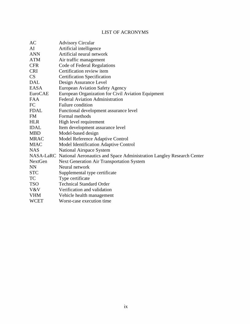
LIST OF ACRONYMS
AC Advisory Circular AI Artificial intelligence ANN Artificial neural network ATM Air traffic management CFR Code of Federal Regulations CRI Certification review item CS Certification Specification DAL Design Assurance Level EASA European Aviation Safety Agency EuroCAE European Organization for Civil Aviation Equipment FAA Federal Aviation Administration FC Failure condition FDAL Functional development assurance level FM Formal methods HLR High level requirement IDAL Item development assurance level MBD Model-based design MRAC Model Reference Adaptive Control MIAC Model Identification Adaptive Control NAS National Airspace System NASA-LaRC National Aeronautics and Space Administration Langley Research Center NextGen Next Generation Air Transportation System NN Neural network STC Supplemental type certificate TC Type certificate TSO Technical Standard Order V&V Verification and validation VHM Vehicle health management WCET Worst-case execution time
ix
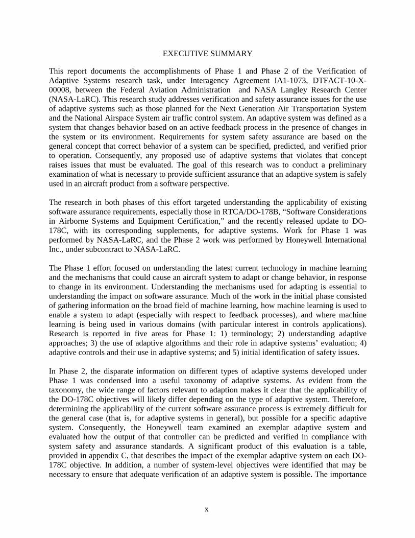
EXECUTIVE SUMMARY
This report documents the accomplishments of Phase 1 and Phase 2 of the Verification of Adaptive Systems research task, under Interagency Agreement IA1-1073, DTFACT-10-X-00008, between the Federal Aviation Administration and NASA Langley Research Center (NASA-LaRC). This research study addresses verification and safety assurance issues for the use of adaptive systems such as those planned for the Next Generation Air Transportation System and the National Airspace System air traffic control system. An adaptive system was defined as a system that changes behavior based on an active feedback process in the presence of changes in the system or its environment. Requirements for system safety assurance are based on the general concept that correct behavior of a system can be specified, predicted, and verified prior to operation. Consequently, any proposed use of adaptive systems that violates that concept raises issues that must be evaluated. The goal of this research was to conduct a preliminary examination of what is necessary to provide sufficient assurance that an adaptive system is safely used in an aircraft product from a software perspective.
The research in both phases of this effort targeted understanding the applicability of existing software assurance requirements, especially those in RTCA/DO-178B, “Software Considerations in Airborne Systems and Equipment Certification,” and the recently released update to DO-178C, with its corresponding supplements, for adaptive systems. Work for Phase 1 was performed by NASA-LaRC, and the Phase 2 work was performed by Honeywell International Inc., under subcontract to NASA-LaRC.
The Phase 1 effort focused on understanding the latest current technology in machine learning and the mechanisms that could cause an aircraft system to adapt or change behavior, in response to change in its environment. Understanding the mechanisms used for adapting is essential to understanding the impact on software assurance. Much of the work in the initial phase consisted of gathering information on the broad field of machine learning, how machine learning is used to enable a system to adapt (especially with respect to feedback processes), and where machine learning is being used in various domains (with particular interest in controls applications). Research is reported in five areas for Phase 1: 1) terminology; 2) understanding adaptive approaches; 3) the use of adaptive algorithms and their role in adaptive systems’ evaluation; 4) adaptive controls and their use in adaptive systems; and 5) initial identification of safety issues.
In Phase 2, the disparate information on different types of adaptive systems developed under Phase 1 was condensed into a useful taxonomy of adaptive systems. As evident from the taxonomy, the wide range of factors relevant to adaption makes it clear that the applicability of the DO-178C objectives will likely differ depending on the type of adaptive system. Therefore, determining the applicability of the current software assurance process is extremely difficult for the general case (that is, for adaptive systems in general), but possible for a specific adaptive system. Consequently, the Honeywell team examined an exemplar adaptive system and evaluated how the output of that controller can be predicted and verified in compliance with system safety and assurance standards. A significant product of this evaluation is a table, provided in appendix C, that describes the impact of the exemplar adaptive system on each DO-178C objective. In addition, a number of system-level objectives were identified that may be necessary to ensure that adequate verification of an adaptive system is possible. The importance
x

of considering adaptive systems starting at the system level is discussed, along with recommendations for follow-on work in AS safety and verification requirements.
xi
1. INTRODUCTION
In the “Decadal Survey of Civil Aeronautics: Foundation for the Future” [1], the National Research Council identified intelligent and adaptive systems as one of the five common threads for the “51 high-priority R&T challenges.” In general, adaptive systems are defined as those that have the ability to change behavior in response to changes in their operational environment, system configuration, resource availability, or other factors. Adaptive systems have been used effectively in a number of application domains, from industrial plant control to missile guidance, though they have not been used in civil aviation. However, that is expected to change. The decadal survey explicitly identified adaptive systems technologies to be the key enablers for intelligent flight controls; advanced guidance and adaptive air traffic management (ATM) systems; and for health management techniques to extend life and improve maintenance.
Adaptive flight and engine control systems have been researched for decades and are attractive for several reasons. There are adaptive systems that have the ability to detect, anticipate, and prevent failures and reconfigure various aircraft systems (e.g., displays or controls) in response; some that simply improve or optimize performance in a changing operational environment; and others that can detect performance degradation due to failure or damage. Expected growth in air traffic is another reason to research the potential. The Next Generation Air Transportation System (NextGen) Integrated Work Plan [2], for example, describes “net-enabled adaptive control of ground, airborne and satellite weather observation sensors in real time” as an enabling capability to meet needs for improved weather observations. Adaptive systems are also being proposed for management of human machine interactions on aircraft and ATM systems to mitigate safety incidents due to failures at the human machine interface. In this case, the emphasis is on the system behavior that adapts to the current context (e.g., tasks, user state, system configuration, environmental states, etc.).
The use of advanced computational techniques, such as those that underlie adaptive systems, is not a new topic in the aviation domain. In 1994, the Federal Aviation Administration (FAA) published a chapter in their Digital Systems Validation Handbook titled “Artificial Intelligence with Applications for Aircraft” [3]. Artificial intelligence (AI) is a broad and rapidly expanding field of technology “devoted to computer programs that will mimic the product of human problem solving, perception, and thought” [3]. The handbook chapter provided an overview of AI technology, focusing on expert systems, and identified potential certification issues for aviation systems that would use those technologies. At that time, expert systems were intended to automate procedures that were already known and serve as assistants or advisors instead of primary decision tools. Today, expert systems are safely used in that capacity in aviation applications.
Adaptive systems, however, have succeeded expert systems as the next AI technology for aviation applications. Adaptive technologies, such as neural networks (NN), can be introduced into the design of a system to achieve a goal such as enhancing performance or efficiency; maintaining desirable behavioral traits, such as robustness; or responding to changes in the system or its environment. Research supported by Eurocontrol investigated an NN-based system for automatic recognition and diagnosis of safety-critical, non-nominal events in ATM for improving safety monitoring for the Single European Sky ATM Research initiative [4].
1

Adaptive systems learn as they execute, thereby exhibiting behavior that can be less predictable than traditional avionics systems. Because requirements for system safety assurance are based on the concept that correct behavior of a system can be specified, predicted, and verified, any use of adaptive systems in civil applications poses challenges in assuring safety by means of traditional safety assurance methods and procedures. This includes understanding the impact of adaptation on system requirements and design and software implementation and verification, because adaptation is ultimately realized through software. The primary aim of the Verification of Adaptive Systems task was to develop an understanding of the ramifications of adaptive systems on software assurance. The task also aimed, to the extent it was possible, to develop a rational and practical approach for the assurance of flight software that uses adaptive techniques, potentially including approaches targeted at the system level. This report documents the results of the two phases of research activity to accomplish those aims. 1.1 OVERVIEW OF PHASE 1 ACTIVITIES
Work on Phase 1 was performed by NASA Langley Research Center. Phase 1 research focused on developing an understanding of the state-of-the-art in adaptive systems technology, especially machine learning, and how adaptive technology is used or proposed to be used in aviation applications, including controls. The following four objectives were defined for Phase 1: Objective 1: Provide definitions of terminology associated with verifying adaptive systems in a
safety-critical airborne environment (e.g., adaptive system, NN, adaptive software, AI, and deterministic).
Objective 2: Describe contrasting characteristics of adaptive systems and deterministic systems, including relative benefits, strengths, and weaknesses.
Objective 3: Investigate the differences between an adaptive approach to system development and a deterministic approach, and their effects on system and software verification.
Objective 4: Identify safety issues when an adaptive, nondeterministic system approach is used and propose mitigation techniques to address these in a safety-critical airborne environment.
The intent of Phase 1 was to lay the groundwork necessary to identify the differences between conventional and adaptive systems from both a requirements and design perspective, and subsequently identify any unique software safety considerations that would not be addressed using existing assurance processes, especially DO-178B [5]. Much of the Phase 1 effort involved gathering information about machine learning and the current uses of adaptive systems in industry, and trying to develop a cogent terminology set associated with the use of machine learning in aviation applications. Sections 2–6 of this report document the results of the Phase 1 effort. Section 2 provides an overview of terminology issues for adaptive systems. Appendix A lists terms and definitions relevant to adaptive systems. Section 3 describes fundamental aspects of adaptive approaches, including strengths and weaknesses, with special emphasis on feedback processes. In section 4, adaptive algorithms are discussed, including NNs, genetic algorithms, and reflective programming. Section 5 presents different approaches to adaptive control. Section 6 then
2
provides an initial assessment of safety issues for adaptive systems. Section 7 contains a summary of the Phase 1 work in preparation for Phase 2. Appendix B provides the results of the literature search as a bibliography. 1.2 OVERVIEW OF PHASE 2 ACTIVITIES
Work in Phase 2 was performed by Honeywell International Inc. The Honeywell team started with the foundational work in Phase 1, then focused Phase 2 activities on determining the extent to which existing guidance in RTCA/DO-178B/C1 and associated supplements can provide the basis for the assurance of adaptive systems, for which additional or alternate objectives and activities might be necessary, and recommendations for additional research. Phase 2 objectives were to: Objective 5: Maximize the current use of DO-178B/C. Where aspects of adaptive systems
cannot be approved using DO-178B/C, provide recommendations for alternate methods to be considered, including the viability of these methods using current technology or as areas where additional research may be necessary.
Objective 6: Make recommendations for the safe use of adaptive systems, especially those
being planned for use in NextGen and National Airspace System (NAS) air traffic control.
Objective 7: Provide effective outputs that can be used by the FAA for the development of
policy, guidance, and training. Sections 7–12 of this report document the results of Honeywell's support for Phase 2. Section 7 provides a transition from Phase 1 activities to Phase 2, including a helpful taxonomy of adaptive systems, based on the different adaptive system types and architectures. Section 8 provides an overview of current certification guidance and standards, including those for system safety and design assurance. Section 9 enumerates and demonstrates concerns about the feasibility of applying DO-178B/C to adaptive systems through the analysis of the objectives against a particular adaptive system. That analysis shows the implications of adaptation on activities and objectives at the system level. Next, section 10 touches on aspects of tool qualification for adaptive systems. Section 11 contains the recommendations for adaptive system safety, and section 12 identifies some continuing research needs. The report concludes with a brief summary of the research effort. 2. TERMINOLOGY
As with many technologies, especially those with application in many diverse domains, there often lacks a standard vernacular used consistently across those domains. This is certainly the
1 During the course of this task, the DO-178B document was updated to DO-178C [6], and four supplementary documents (covering object-oriented technology, model-based development, formal methods, and tool qualification) were approved by the RTCA Inc. Phase 2 activities considered the changes to those documents in the course of the research. The term DO-178B/C indicates that consideration.
3
case with adaptive systems. Work on this task started with an effort to define terminology associated with adaptive systems, including terms such as “adaptive system”, “neural network”, “adaptive software”, “artificial intelligence”, and “deterministic”. It did not take long to realize that the terms often used when discussing adaptive systems in the aviation domain do not reflect the latest technology current in machine learning. Consequently, the simple task of defining terminology evolved into an effort to explore and understand the burgeoning world of machine learning and its applicability to aviation applications. Throughout this research effort, a list of relevant terms and definitions were compiled while reviewing source material obtained through a broad literature search. The literature search for this effort culminated in over 206 references, including textbooks; conference proceedings; journal publications; standards and guidelines; industry papers; academic sites; and other online resources. Appendix A contains a list of terms and definitions, and appendix B lists the results of the literature search in a bibliography. A few additional terms and definitions provide the context for the remainder of this report. The first term is “adaptive system”. For this study, an adaptive system is one in which the behavior changes in response to an active feedback process to achieve a goal in the presence of changes in the system environment. That environment might be the computational environment, including the components of the computing platform, such as middleware, or might be the physical or external system in which the computer program operates. For airborne systems, changes to the environment might include change to the physical structure of the aircraft or change in the weather. Behavior change, in response to an adaptive technique such as an NN, is not intended to imply behavior change only when the system is operating in service. Behavior changes might be explored during the design phase of a system, in which an adaptive algorithm is used to help define the behavior of a system. In this case, at the end of the system design phase, the design can be fixed such that the feedback mechanism is no longer needed and the behavior does not adapt in real-time operation of that software. In other cases, the behavior change from the feedback of an adaptive system may take place on a continuous basis in real-time operation (referred to as a fully adaptive system), or only periodically (referred to as a partially adaptive system). The definition of adaptive system used in this report does not include the term “deterministic” or its complement “nondeterministic”—terms that are often used to attempt to distinguish between a system that adapts and one that does not. In appendix A, a deterministic system is defined as one in which no randomness is involved in the development of future states of the system. Given the same input, the future state of a deterministic system can be precisely determined or predicted from knowledge of an initial system state and a predictable sequence of intermediate states. In theory, determinism precludes the existence of randomness that influences the intermediate states. A system influenced by random processes would be nondeterministic, because the future state of the system cannot be uniquely predicted from a defined sequence of intermediate states.
4

In practice, all physical systems have random processes or uncertainties at some level. For example, there is likely to be noise in system electronics or in sensor data used within the system. Being predictable does not necessarily imply that a deterministic system is free from any random processes or other uncertainties; rather, the implication is that these factors do not cause appreciable variations in the observed behavior of the system. Depending on the internal system processes (such as filters applied to the sensor data), these effects may not be detectable at the system interface, or their impact on the system behavior may be negligible. For example, consider the case of multithreaded programs [7]:
Non-determinism, inherent in threaded applications, causes significant challenges for parallel programmers by hindering their ability to create parallel applications with repeatable results…
Application developers rely heavily on the fact that given the same input, a program will produce the same output. Sequential programs, by construction, typically provide this desirable property of deterministic execution. However, in shared memory multithreaded programs, deterministic behavior is not inherent. When executed, such applications can experience one of many possible interleavings of memory accesses to shared data. As a result, multithreaded programs will often execute non-deterministically following different internal states that can sometimes lead to different outputs.
In this case, threaded programs can be considered deterministic if the uncertainties associated with concurrency issues are properly considered in the software design. Though the exact central processing unit cycle occupied by a particular floating point operation may vary dramatically frame to frame, the important factor for deterministic behavior will likely be that the entire computation is complete before the frame deadline.
For adaptive systems, the output may be deterministic or nondeterministic, depending on where and how the feedback process is used. Because the terms “deterministic” and “nondeterministic” are complex, those terms are not used in the remainder of this report. The issues of concern with respect to software assurance are related to having sufficient understanding, predictability, and verification of the effect of the adaptation; therefore, this report focuses on understanding that process.
5
3. UNDERSTANDING ADAPTIVE APPROACHES
There are many dimensions to adaptive systems. According to McCormick [8], “adaptive systems can be characterized by how aggressively they attempt to adapt to the unexpected. In the simplest case, adaptive systems behave like a complex curve-fitting or pattern-matching mechanism. In more complex cases, they are designed to learn continuously from their environments.” The following four factors are important to understanding adaptive approaches from this perspective, and understanding the issues relevant to assurance of systems using these approaches: 1. The feedback process. 2. The system life cycle context where adaptation is actively used. 3. How learning takes place. 4. The role of the adaptive approach. 3.1 THE FEEDBACK PROCESS
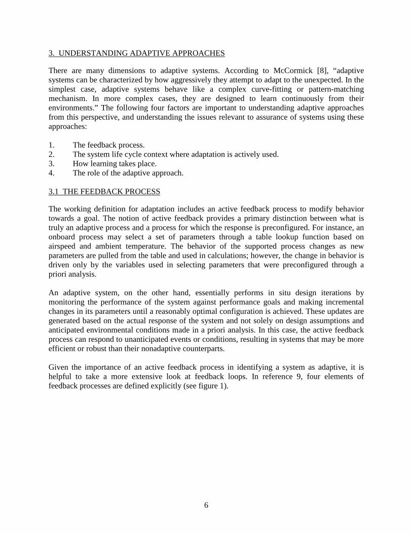
The working definition for adaptation includes an active feedback process to modify behavior towards a goal. The notion of active feedback provides a primary distinction between what is truly an adaptive process and a process for which the response is preconfigured. For instance, an onboard process may select a set of parameters through a table lookup function based on airspeed and ambient temperature. The behavior of the supported process changes as new parameters are pulled from the table and used in calculations; however, the change in behavior is driven only by the variables used in selecting parameters that were preconfigured through a priori analysis. An adaptive system, on the other hand, essentially performs in situ design iterations by monitoring the performance of the system against performance goals and making incremental changes in its parameters until a reasonably optimal configuration is achieved. These updates are generated based on the actual response of the system and not solely on design assumptions and anticipated environmental conditions made in a priori analysis. In this case, the active feedback process can respond to unanticipated events or conditions, resulting in systems that may be more efficient or robust than their nonadaptive counterparts. Given the importance of an active feedback process in identifying a system as adaptive, it is helpful to take a more extensive look at feedback loops. In reference 9, four elements of feedback processes are defined explicitly (see figure 1).
6
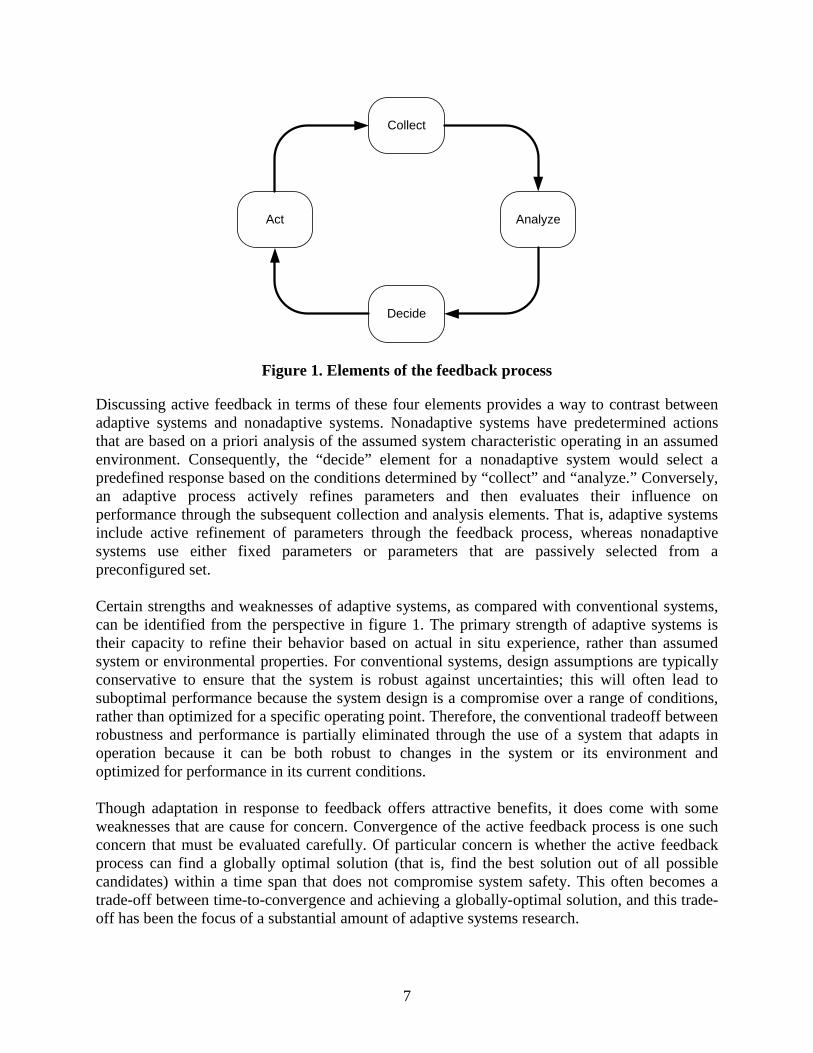
Figure 1. Elements of the feedback process
Discussing active feedback in terms of these four elements provides a way to contrast between adaptive systems and nonadaptive systems. Nonadaptive systems have predetermined actions that are based on a priori analysis of the assumed system characteristic operating in an assumed environment. Consequently, the “decide” element for a nonadaptive system would select a predefined response based on the conditions determined by “collect” and “analyze.” Conversely, an adaptive process actively refines parameters and then evaluates their influence on performance through the subsequent collection and analysis elements. That is, adaptive systems include active refinement of parameters through the feedback process, whereas nonadaptive systems use either fixed parameters or parameters that are passively selected from a preconfigured set. Certain strengths and weaknesses of adaptive systems, as compared with conventional systems, can be identified from the perspective in figure 1. The primary strength of adaptive systems is their capacity to refine their behavior based on actual in situ experience, rather than assumed system or environmental properties. For conventional systems, design assumptions are typically conservative to ensure that the system is robust against uncertainties; this will often lead to suboptimal performance because the system design is a compromise over a range of conditions, rather than optimized for a specific operating point. Therefore, the conventional tradeoff between robustness and performance is partially eliminated through the use of a system that adapts in operation because it can be both robust to changes in the system or its environment and optimized for performance in its current conditions. Though adaptation in response to feedback offers attractive benefits, it does come with some weaknesses that are cause for concern. Convergence of the active feedback process is one such concern that must be evaluated carefully. Of particular concern is whether the active feedback process can find a globally optimal solution (that is, find the best solution out of all possible candidates) within a time span that does not compromise system safety. This often becomes a trade-off between time-to-convergence and achieving a globally-optimal solution, and this trade-off has been the focus of a substantial amount of adaptive systems research.
Decide
Act
Collect
Analyze
7

A second related concern, which is also relevant to the active feedback path, is whether the analysis and decision elements of the feedback process are focusing on the correct features within the feedback signal. For example, it is possible to focus the adaptation on noise rather than on the underlying signal that represents the true dynamics of the system, without sufficient attention to mitigations to prevent this. Finally, one strength of a conventional approach is that the critical performance parameters of the system can be predicted (to some degree) for any given system configuration and environmental condition, whereas the performance of an adaptive system can only be predicted if the learning history of the system is known. 3.2 LIFE CYCLE CONTEXT
Identifying where the adaptation occurs in the system life-cycle is an important aspect of adaptive systems. Adaptive systems can be divided into those that use adaptive approaches for development only, typically to mature a design, and those for which the active feedback system is active in real-time operation. One benefit of using an adaptive approach during the design phase is that a detailed understanding of the underlying physical process may not be necessary for the adaptive approach to converge on an acceptable design solution. For example, if data is available to describe the intended input/output behavior of a complex interaction, it may be feasible to train an NN to replicate this behavior to a specified accuracy. In this case, a mathematical model of the underlying process, based on principles of physics, thermodynamics, or other disciplines, does not need to be derived. One of the major strengths of this approach is that it provides a means for developing representations of complex systems for which derivation of a mathematical model by hand may be prohibitively difficult or impossible. By the same token, using an adaptive approach during the design phase may circumvent the need for a detailed understanding of an underlying process. This is a weakness because the outcome of the underlying process becomes encoded in the input and output data used to train the adaptive process, and the structure of the NN algorithm that is trained on this data bears little to no resemblance to the actual process being modeled. This leads to a lack of traceability between the resulting algorithmic design and the underlying process being modeled. Additionally, it underscores the necessity that the intended behavior be fully captured within the data used to train the adaptive system as part of development. 3.3 LEARNING METHOD
Many of the adaptive approaches identified in this study fall under the auspices of machine learning techniques. Machine learning is a branch of AI concerned with the development of algorithms that allow computers to evolve behaviors based on observing and making statistical inferences about data. A major focus of machine learning research is to automatically recognize (learn or be trained to recognize) complex patterns and make intelligent decisions based on data. As the computational power of computers has increased, so has the ability of algorithms to evaluate large amounts of data to automatically recognize complex patterns, to distinguish between exemplars based on their different patterns, and to make predictions. Many advances in
8
adaptive control algorithms, for example, are based on the ability to rapidly process data representing the aircraft’s environment and make similarly rapid changes in parameters intended to maintain stability when that environment changes unexpectedly.
Learning is accomplished through inductive inference—that is, making predictions based on observations. These predictions are based on the observation of data that represents incomplete information about statistical phenomenon and generalizing it into rules and making predictions of missing attributes or future data. The process of learning from observations is often characterized by three different types of learning: supervised, unsupervised, and reinforcement learning:
• Supervised learning (or learning by example) is done with predetermined sets of datarepresenting input and response relations. The machine learning algorithm generates amodel in terms of a mathematical function of the relationship between input data andresponse based on the predetermined training. This model can be used to predict theresponse to input that was not included in the training data. Training data typicallyconsists of examples in the form of an input value or values paired with a desired output.
• Supervised learning can also occur in an operational context if a model is provided thatcan describe the desired system response. Comparing the desired against the actualresponse provides a means for measuring the performance of the adaptive system. Usingthis performance measure in an active feedback loop provides a way for the adaptivesystem to perform supervised learning while in operations.
• Unsupervised learning applies statistical techniques to identify non-obvious relationshipswithin the data. With this approach, the learning algorithm is not given any targetinformation to guide it nor is the algorithm given feedback based on previous decisions oractions. In a sense, unsupervised learning can be thought of as finding patterns in the databeyond what would be considered pure unstructured noise.
• Reinforcement learning involves mapping situations to actions to maximize a cumulativereward obtained through a number of intermediate actions. Reinforcement learning isoften called “learning from experience” or “learning through interaction.” The learner isnot told which actions to take, as in supervised learning, but instead must discover whichintermediate actions yield the best results. In the most interesting and challenging cases,actions may affect not only the immediate reward, but also the next situation and, throughthat, all subsequent rewards. These two characteristics—trial-and-error search anddelayed reward—are often referred to as “exploration” and “exploitation” and are the twomost important distinguishing features of reinforcement learning.
In general, of the three types of learning methods, supervised learning poses the fewest challenges with respect to verification.
9
3.4 ROLE OF ADAPTATION
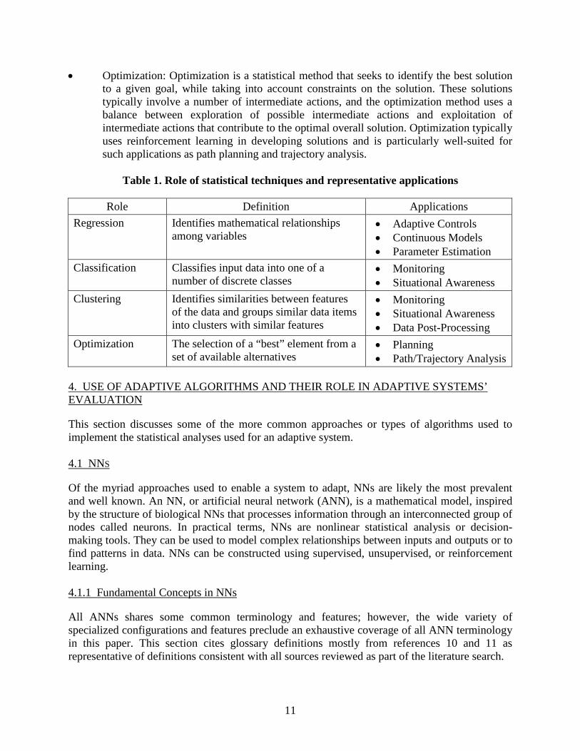
Machine learning algorithms that enable adaptation are statistics-based algorithms designed to identify complex patterns and make decisions based on data. The statistical task generally has one of four purposes, associated with different application domains, as shown in table 1: • Regression: Many application domains, such as controls or sensor processing, require an
accurate mathematical relationship of the physical system, its environment, or some process within the system. When the exact relationship is unknown, a conservative representation is often used because of uncertainties or approximations that are necessary to reduce the complexity of the mathematical relationship to a reasonable level. In other instances, the process, system, or environment is too complex for a mathematical expression to be derived from physical principles associated with dynamics, thermodynamics, or other related disciplines. Adaptive techniques such as NNs provide a way for an accurate mathematical relationship to be generated from heuristic data: representative input/output data is processed using statistical methods to converge on a mathematical representation of the data. The resulting algorithm can then be fixed if it is developed exclusively as part of the design process, or the adaptive process can continue to refine the representation in operations. Continuous models developed using regression analysis are often used in adaptive controls and parameter estimation applications. Typically, this involves the use of supervised learning.
• Classification: Classification is closely associated with regression; however, the statistical
methods used for classification seek to place each input data item into one of a finite set of possible outcomes. Statistical methods used for classification produce discrete models that categorize the results, whereas regression analysis produces continuous models. Some statistical methods used for classification generate new classes if a suitable match is not found for a given input. In other approaches, the set of possible outcomes is fixed in advance.
Classification can be used for situational awareness in which inputs are classified according to features relevant to the monitor. Classification can also be used for pattern recognition, such as image processing, where a best match is selected from an image database on which the adaptive approach is trained. Classification typically involves supervised learning, but can also include unsupervised learning for instances in which the adaptive system is allowed to generate new classifications.
• Clustering: Clustering analysis assigns a set of objects into groups, called clusters, so that
the objects in the same cluster are more similar, in some sense or another, to each other than to those in other clusters. Clustering is a statistical technique that is particularly powerful in identifying relationships in the data that are not otherwise obvious through conventional methods of data analysis. Clustering is often used as a data post-processing technique to identify trends or indicators. Some forms of clustering are applicable to in situ, real-time health monitoring environments in which they may be able to identify precursors to adverse conditions. Clustering generally uses unsupervised learning.
10
• Optimization: Optimization is a statistical method that seeks to identify the best solutionto a given goal, while taking into account constraints on the solution. These solutionstypically involve a number of intermediate actions, and the optimization method uses abalance between exploration of possible intermediate actions and exploitation ofintermediate actions that contribute to the optimal overall solution. Optimization typicallyuses reinforcement learning in developing solutions and is particularly well-suited forsuch applications as path planning and trajectory analysis.
Table 1. Role of statistical techniques and representative applications
Role Definition Applications Regression Identifies mathematical relationships
among variables • Adaptive Controls• Continuous Models• Parameter Estimation
Classification Classifies input data into one of a number of discrete classes
• Monitoring• Situational Awareness
Clustering Identifies similarities between features of the data and groups similar data items into clusters with similar features
• Monitoring• Situational Awareness• Data Post-Processing
Optimization The selection of a “best” element from a set of available alternatives
• Planning• Path/Trajectory Analysis
4. USE OF ADAPTIVE ALGORITHMS AND THEIR ROLE IN ADAPTIVE SYSTEMS’EVALUATION
This section discusses some of the more common approaches or types of algorithms used to implement the statistical analyses used for an adaptive system.
4.1 NNS
Of the myriad approaches used to enable a system to adapt, NNs are likely the most prevalent and well known. An NN, or artificial neural network (ANN), is a mathematical model, inspired by the structure of biological NNs that processes information through an interconnected group of nodes called neurons. In practical terms, NNs are nonlinear statistical analysis or decision-making tools. They can be used to model complex relationships between inputs and outputs or to find patterns in data. NNs can be constructed using supervised, unsupervised, or reinforcement learning.
4.1.1 Fundamental Concepts in NNs
All ANNs shares some common terminology and features; however, the wide variety of specialized configurations and features preclude an exhaustive coverage of all ANN terminology in this paper. This section cites glossary definitions mostly from references 10 and 11 as representative of definitions consistent with all sources reviewed as part of the literature search.
11

A neuron is a basic computation element of the NN [11], consisting of a weighted sum of input connections, passed through an activation function (also called a threshold function), that is typically nonlinear, such as a hyperbolic tangent or another sigmoid (S-shaped) function, as shown in figure 2 [12].
Figure 2. Model of a neuron
The adaptive feedback process for ANNs refines each weight, defined as the “numerical values attached to specific neuron inputs to indicate significance” [11]. The topology of the ANN, which is the manner and organization in which the neurons are connected together [11], varies significantly for different types of ANNs; however, a common form contains an input layer of neurons (f1 through f3 in figure 3, taken from reference 13), one or more hidden layers (f4 and f5), and an output layer (f6).
Figure 3. NN topology
The number of neurons in the input layer corresponds to the number of inputs to the system. Though linear systems require the inputs to be linearly independent, this restriction is not placed on NNs, which makes them attractive for systems with data sources that may be related. Similarly, the number of outputs is not restricted to one. The topology represented above is a feedforward network, defined as “a network in which signal paths can never return to the same signal node” [14]. This is in contrast to a feedback network, defined as “a network in which signal paths can return to the same signal node” [14], which would be represented in figure 3 by right-to-left signal arrows between neurons; this implies a temporal dependence of the network on its previous states, whereas a feedforward network has no such state dependency and is a function only of its current inputs. Feedforward networks are prevalent in the literature discussing the application of ANNs to safety-critical systems, with the above topology usually identified as a multilayer perceptron.
12

Many applications of this topology include only one hidden layer, with the number of neurons in the layer driven by the intrinsic characteristics of the phenomenon the ANN is intended to approximate. Initial observations about the phenomenon are provided to the ANN through training using training data, sometimes referred to as the training set. Training data consists of input and desired output data pairs used to train the system. This data allows the NN to learn the appropriate response to predefined stimuli [10, 11] by adjusting certain parameters.
Note that a data pair does not imply single input/single output training data—the pair would instead consist of an input vector and an associated output vector. A useful delineation between training and learning is: • Learning—The modification of an NN’s behavior in response to its environment [11].
• Training—Learning using preoperation knowledge that defines the appropriate response to predefined stimuli.
For ANNs, the primary distinction between training and learning in general is the context. Training encompasses learning that occurs outside of an operational context in a controlled environment (such as during system development), whereas, in general, learning may also occur during operation. This distinction will serve as a primary discriminator in the following discussion of the use of ANNs in a safety-critical system; concerns regarding ANNs that are trained during development and then fixed (no additional learning occurs during operations) vary significantly from concerns regarding the use of ANNs that continue to learn during operations (dynamic). In feedforward networks, the common approach to learning is through the use of a back-propagation scheme. In simple terms, once the network has processed the input from the training data, the network looks at the difference between the network’s response and the expected response and then the weights associated with the nodes of the network are adjusted by working backwards through the network. Though there are numerous variations, back-propagation typically involves a gradient descent learning rule that influences the adjustment of the network weights in the direction of the steepest error gradient, as shown in figure 4.
13

Figure 4. Gradient descent learning rules
In figure 4(A), starting at point 1, the gradient descent rule implies that the weights are adjusted so that the response of the system is influenced towards point 2. At the subsequent application of the same training data, the gradient at point 2 will influence the response in the same direction, resulting in an overshoot of the global minimum shown in the figure as a solid dot. The gradient descent at point 3 would then influence the solution back towards the global minimum, with the magnitude of the gradient influencing the step size. This repeats until the process converges on the global minimum error within an acceptable tolerance. Figure 4(B) shows the common concern that learning converges on a local minimum, resulting in significantly higher training error then would be achieved at the global minimum. Sophisticated back-propagation schemes have been developed to improve the speed of convergence on a global minimum error and avoid convergence to a local minimum error. 4.1.2 Example Application of an NN
Work performed by Goodrich and Barron Associates in applying an NN to an in-flight fuel measurement system provides a good example of the use of an NN in an airborne application [15, 16]. The conventional approach to a fuel measurement system involves the development of a multi-dimensional lookup table that maps fuel sensor signals to fuel levels. Because of the shape of the fuel tanks and nonlinearities of the sensors, it is not analytically feasible to develop a mathematical expression for this nonlinear estimation problem. Instead, nonlinear data is generated by a complex high-fidelity model of the fuel system and tabularized into a form that can be indexed by a table lookup software function. The table resulting from this approach requires a very large memory footprint. Furthermore, this approach requires each sensor input to be treated as an independent degree of freedom (a separate table dimension) when in actuality significant coupling may exist between sensors that can be exploited to generate more accurate measurements. These two reasons motivated research into using an NN to represent the mapping between sensor data and fuel measurements. Figure 5 shows a comparison between the conventional approach and the NN approach.
14
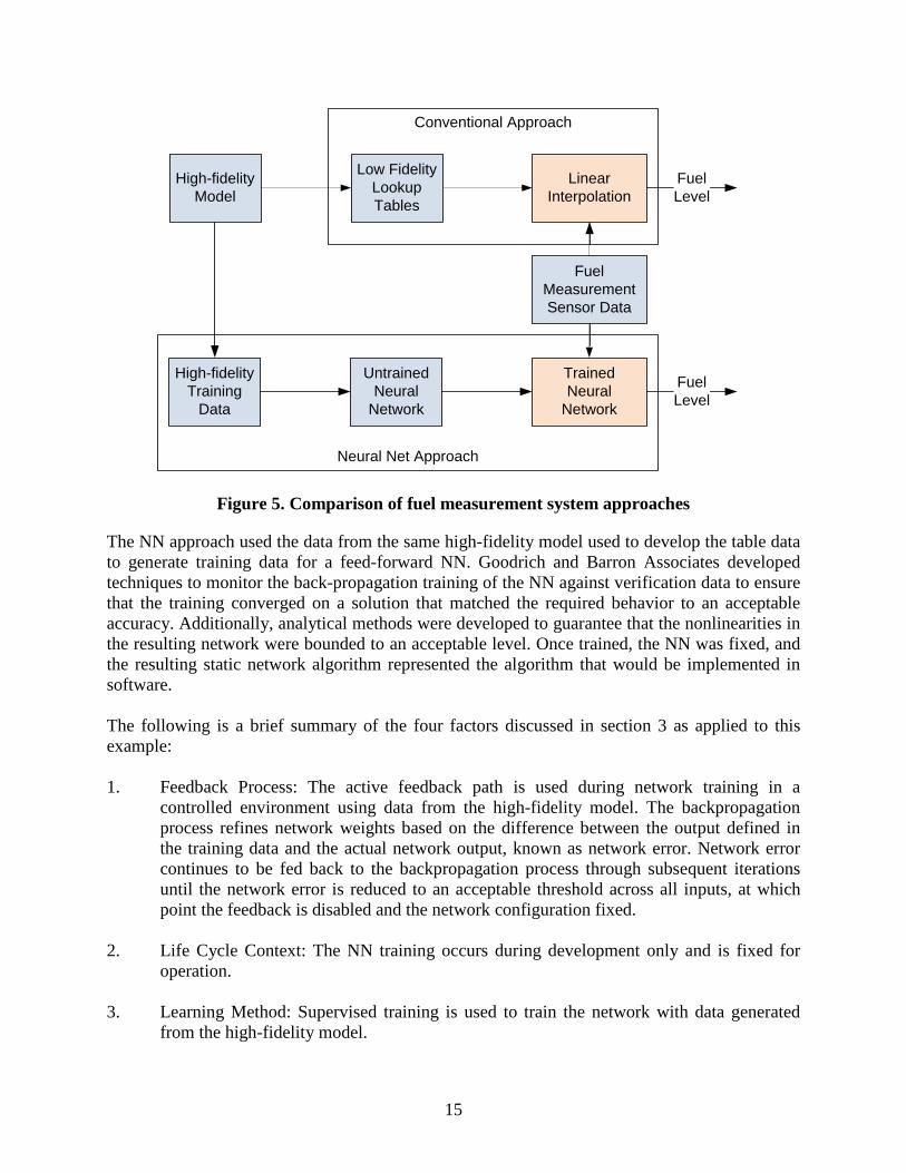
Figure 5. Comparison of fuel measurement system approaches
The NN approach used the data from the same high-fidelity model used to develop the table data to generate training data for a feed-forward NN. Goodrich and Barron Associates developed techniques to monitor the back-propagation training of the NN against verification data to ensure that the training converged on a solution that matched the required behavior to an acceptable accuracy. Additionally, analytical methods were developed to guarantee that the nonlinearities in the resulting network were bounded to an acceptable level. Once trained, the NN was fixed, and the resulting static network algorithm represented the algorithm that would be implemented in software. The following is a brief summary of the four factors discussed in section 3 as applied to this example: 1. Feedback Process: The active feedback path is used during network training in a
controlled environment using data from the high-fidelity model. The backpropagation process refines network weights based on the difference between the output defined in the training data and the actual network output, known as network error. Network error continues to be fed back to the backpropagation process through subsequent iterations until the network error is reduced to an acceptable threshold across all inputs, at which point the feedback is disabled and the network configuration fixed.
2. Life Cycle Context: The NN training occurs during development only and is fixed for
operation. 3. Learning Method: Supervised training is used to train the network with data generated
from the high-fidelity model.
Neural Net Approach
Conventional Approach
High-fidelityModel
Low FidelityLookup Tables
LinearInterpolation
FuelMeasurementSensor Data
High-fidelityTraining
Data
UntrainedNeural
Network
TrainedNeural
Network
FuelLevel
FuelLevel
15
4. Role of Adaptation: The statistical analysis method is regression analysis between the input (sensors) and output (fuel measurement). This is a nonlinear, continuous model of the process.
The NN approach compares to the conventional table-lookup approach for fuel measurement as follows: • Training through the backpropagation resulted in a compact algorithmic representation of
the fuel management system when no analytical solution could be derived through conventional means. This resulted in a representation that required far fewer computational resources than the conventional approach.
• Specific analysis was necessary to verify that all nonlinearities within the network were
suitably bounded and would not result in unintended network behavior. • Because the network was fixed for operations, the concerns regarding its use in
operations are much the same as would be expressed for a conventional approach (assuming that the nonlinear nature of the algorithm has been thoroughly reviewed).
• The use of supervised training provided the means to quantify the network error and
establish that the network error met an acceptable tolerance across the input space. Verification data, independent of the training data, was used to verify that network was not overtrained. Note that the use of supervised training requires verification that all intended functionality is completely expressed within the training data.
4.1.3 Observations Concerning NNs
A strong appeal of NNs is that they can be trained to represent nonlinear relationships. Nonlinearity is also the source of many of the concerns with the use of NNs. Discontinuities, regions of the data that are highly nonlinear, and the presence of a significant number of inflections may indicate that (a) training may be difficult, and (b) the ANN topology may be inordinately complex. Accordingly, verification that the nonlinearities in the network are well behaved and bounded is a critical verification task. In addition, if an NN is adaptive in operation, specific consideration must be given to the integrity of the convergence of the training and the stability of the network in general. Finally, because the training is encoded in the network through the refinement of the neuron weights, the relationship between the network structure and the process that the network represents is often difficult or impossible to ascertain analytically. In other words, traceability between the network and the requirements addressed by the network often cannot be evaluated by inspection; it is only through demonstrating that the network behavior is representative of the specified behavior that the traceability can be established. 4.2 GENETIC ALGORITHMS
A genetic algorithm is a stochastic search method that mimics the process of natural selection and the resulting changes in genetic composition. Whereas most stochastic search methods operate on a single solution to the problem at hand, genetic algorithms operate on a population of
16

solutions. Genetic algorithms are often used to generate useful solutions to optimization and search problems. To use a genetic algorithm, one must encode solutions to a problem in a structure that can be stored in the computer. This object is called a genome (or chromosome). The genetic algorithm creates a population of genomes and then applies evolutionary operations to the individuals in the population to generate new individuals. It uses various selection criteria so that it picks the best individuals for further evolution. Genetic programming is a specialization of genetic algorithms in which each individual genome is a computer program. It is used to optimize a population of computer programs according to a fitness landscape determined by a program’s ability to perform a given computational task. Genetic programming evolves a population of computer programs; that is, generation to generation, genetic programming stochastically transforms populations of programs into new, hopefully better, populations of programs. A generic algorithm for genetic algorithms is as follows:
• Randomly create an initial population of genomes representing a valid solution • REPEAT
− Analyze the population to ascertain their fitness − Select one or two from the population with a probability based on fitness to
participate in genetic operations − Create new individuals by applying genetic operations with specified probabilities
• UNTIL an acceptable solution is found or another stopping condition is met • RETURN the selected member of the population Genetic programming, like nature, is a random process, and it can never guarantee results. As such, the likelihood that this particular approach for an adaptive system would be considered for use in a civil airborne application is extremely small. 4.3 REFLECTION/AUTONOMIC COMPUTING
In computer science, reflection is the process by which a computer program can observe and modify its own structure and behavior at runtime. Reflective/autonomic computing is computation carried out on data representing the state of an executing system’s hardware, software components, and their interactions. This is typically accomplished by dynamically assigning program code at runtime. Self-adaptive reflective middleware uses reflective computation to adapt its behavior in response to evolving conditions such as system performance. For instance, a single node might alter the thread schedule for high-demand services, a distributed computing system might replicate services that are under high demand to multiple nodes, or a particular protocol may be selected based on monitoring network traffic.
17
4.4 SUPPORTING TECHNOLOGIES
Two additional technologies, fuzzy logic and expert systems, are mentioned here to supplement the algorithms described above. These technologies are not adaptive; that is, they do not have a feedback loop:
1. Fuzzy Logic: This is a form of many-valued logic derived from fuzzy set theory to dealwith reasoning that is fluid or approximate rather than fixed and exact. Fuzzy logic is asuperset of conventional (Boolean) logic that has been extended to handle the concept ofpartial truth, in which the truth value may range between completely true and completelyfalse. Fuzzy logic was developed for complex control systems in which mathematicalmodels were difficult or impossible to create, such as in highly nonlinear systems. It hasbeen evaluated for use in a variety of control applications, including flight controls [3 and17]. Fuzzy logic can be combined with an NN to produce an adaptive fuzzy controlsystem.
2. Expert Systems: This is a computer-based system design to emulate the problem-solvingbehavior of a human expert [3]. An expert system usually is comprised of a rule base andan inference engine that cooperate to simulate the reasoning process that a human expertpursues in analyzing a problem and arriving at a conclusion. An expert system can bemade adaptive if an adaptive technology is used to refine the inference weights based onfeedback from the user.
5. ADAPTIVE CONTROLS AND THEIR USE IN ADAPTIVE SYSTEMS
This section provides an overview of adaptive controls that is separate from a discussion of the other adaptive technologies because of the distinct use of feedback for control systems. A summary of concepts and terms relevant to control systems is provided first, followed by a discussion of conventional and adaptive controls. Then, representative adaptive control system architectures are discussed to illustrate the variety of adaptive control approaches.
The field of adaptive controls is extremely wide, and this section provides only a short overview of a few representative approaches. Note that other adaptive mechanisms, such as NNs, may be used to provide the adaptivity within the control system. Accordingly, this section focuses on the general concept of adaptive controls, rather than the specific form of the adaptive mechanisms used within the control system.
5.1 CONTROL SYSTEM OVERVIEW
A control system is the combination of, at a minimum, a controller connected to the physical system being controlled. A closed loop control system (shown in figure 6) is formed by connections between an externally provided command (“Cmd”); the controller and the actuator(s) of the physical system; and the feedback from the sensor(s) of the physical system to the controller. The controller feedback provides measured aspects of the physical response, such as rates or positions, depending on the type of sensors used in the feedback path.
18
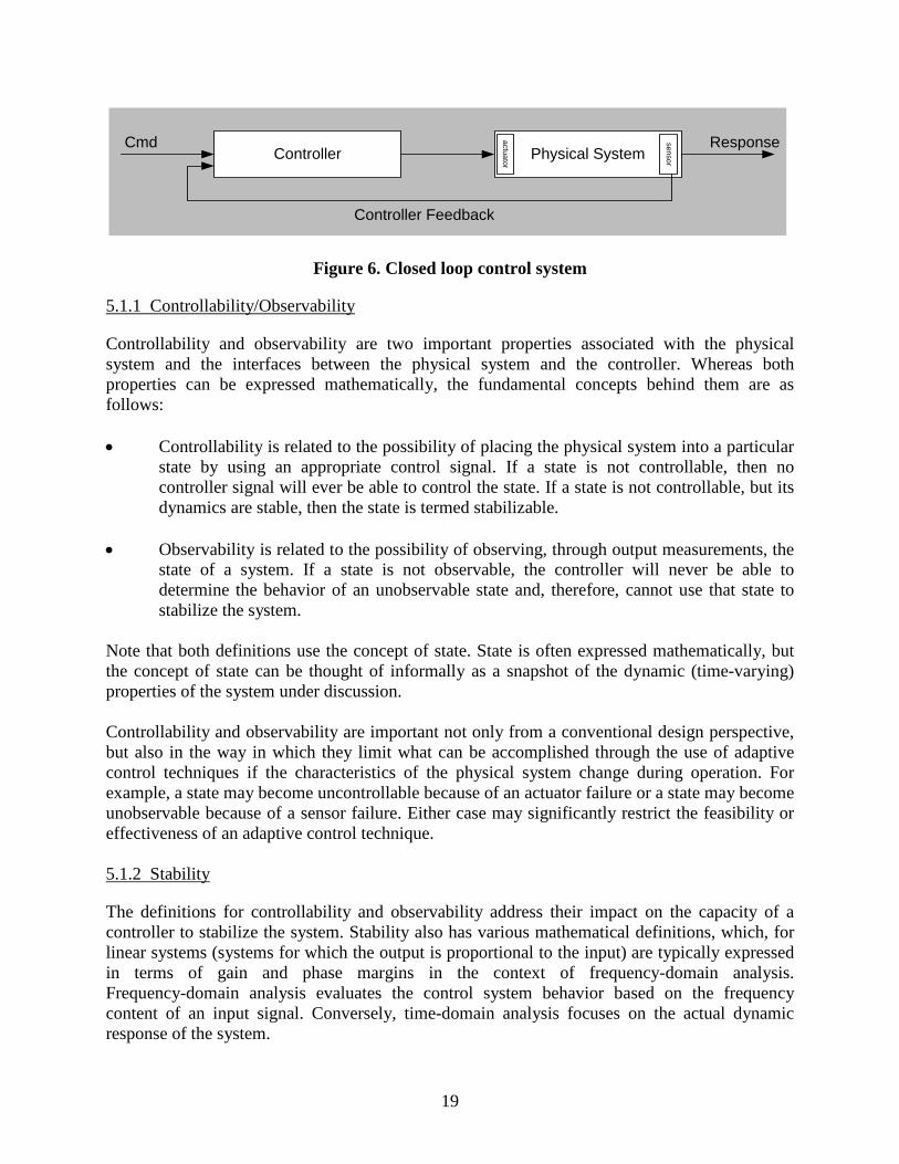
Figure 6. Closed loop control system
5.1.1 Controllability/Observability
Controllability and observability are two important properties associated with the physical system and the interfaces between the physical system and the controller. Whereas both properties can be expressed mathematically, the fundamental concepts behind them are as follows: • Controllability is related to the possibility of placing the physical system into a particular
state by using an appropriate control signal. If a state is not controllable, then no controller signal will ever be able to control the state. If a state is not controllable, but its dynamics are stable, then the state is termed stabilizable.
• Observability is related to the possibility of observing, through output measurements, the
state of a system. If a state is not observable, the controller will never be able to determine the behavior of an unobservable state and, therefore, cannot use that state to stabilize the system.
Note that both definitions use the concept of state. State is often expressed mathematically, but the concept of state can be thought of informally as a snapshot of the dynamic (time-varying) properties of the system under discussion. Controllability and observability are important not only from a conventional design perspective, but also in the way in which they limit what can be accomplished through the use of adaptive control techniques if the characteristics of the physical system change during operation. For example, a state may become uncontrollable because of an actuator failure or a state may become unobservable because of a sensor failure. Either case may significantly restrict the feasibility or effectiveness of an adaptive control technique. 5.1.2 Stability
The definitions for controllability and observability address their impact on the capacity of a controller to stabilize the system. Stability also has various mathematical definitions, which, for linear systems (systems for which the output is proportional to the input) are typically expressed in terms of gain and phase margins in the context of frequency-domain analysis. Frequency-domain analysis evaluates the control system behavior based on the frequency content of an input signal. Conversely, time-domain analysis focuses on the actual dynamic response of the system.
Controller Physical SystemResponseCmd
Controller Feedback
actuator
sensor
19

5.1.3 Robustness
The robustness of a control system is defined as the quality of maintaining designed controller stability and performance properties in the presence of uncertainties in the system or unmodeled disturbances. Gain and phase margins provide a standard approach for ensuring robustness for linear systems. Robustness can be evaluated in frequency-domain analysis by confirming that positive stability margins remain for small variations in dynamics or modeling assumptions. This analysis covers both independent and coupled variations. Robustness analysis is then extended into time-domain analysis where additional effects are included, such as system nonlinearities for which stability impacts were approximated through linearization in frequency-domain analysis. 5.1.4 Robustness of Non-Adaptive Control Systems
For a non-adaptive control system, controller parameters such as gains and filter coefficients are determined during design and then fixed for operations. As a result, the controller design is based on a priori knowledge and assumptions regarding the dynamics of the physical system operating in its environment. Performance and robustness of the control system may degrade if the actual dynamics of the physical system, or the actual environment, do not match what was assumed while developing the controller. Non-adaptive control design methods result in a fixed controller for a design point defined by a specific physical system operating in a specific environment. Some methods, such as robust control theory, account for uncertainties and disturbances within the physical system as part of the design methodology. These methods still result in a fixed controller, albeit one with more robust characteristics than what might result from more classical design methods. Additional analysis can assess the robustness of the control system by varying the properties of the physical system or the environment away from this design point. For many application domains, such as aircraft flight controls, multiple design points can be used to maintain robustness across the range of operations. Frequently, the same controller architecture can be used across the design points, with the only variations being in controller parameters such as gains and filter coefficients required to tune the controller for each point. For these situations, a gain scheduling approach can be used to select the correct set of parameters based on look-up tables generated during design, as shown in figure 7. Note that the shaded area in figure 7 and subsequent figures represents the structure of the conventional control system shown. This does not imply that the controller in the shaded area remains unchanged from the one shown in figure 6; instead, it is intended to show the evolution of various control system approaches away from the conventional baseline. In this instance, the structure of the controller is fixed, but the parameter values used within the controller are passed in from the gain schedule tables. Note also that the sensor/actuator dynamics are assumed, for the sake of simplicity, to be part of the physical system.
20
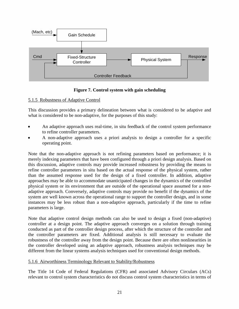
Figure 7. Control system with gain scheduling
5.1.5 Robustness of Adaptive Control
This discussion provides a primary delineation between what is considered to be adaptive and what is considered to be non-adaptive, for the purposes of this study:
• An adaptive approach uses real-time, in situ feedback of the control system performanceto refine controller parameters.
• A non-adaptive approach uses a priori analysis to design a controller for a specificoperating point.
Note that the non-adaptive approach is not refining parameters based on performance; it is merely indexing parameters that have been configured through a priori design analysis. Based on this discussion, adaptive controls may provide increased robustness by providing the means to refine controller parameters in situ based on the actual response of the physical system, rather than the assumed response used for the design of a fixed controller. In addition, adaptive approaches may be able to accommodate unanticipated changes in the dynamics of the controlled physical system or its environment that are outside of the operational space assumed for a non-adaptive approach. Conversely, adaptive controls may provide no benefit if the dynamics of the system are well known across the operational range to support the controller design, and in some instances may be less robust than a non-adaptive approach, particularly if the time to refine parameters is large.
Note that adaptive control design methods can also be used to design a fixed (non-adaptive) controller at a design point. The adaptive approach converges on a solution through training conducted as part of the controller design process, after which the structure of the controller and the controller parameters are fixed. Additional analysis is still necessary to evaluate the robustness of the controller away from the design point. Because there are often nonlinearities in the controller developed using an adaptive approach, robustness analysis techniques may be different from the linear systems analysis techniques used for conventional design methods.
5.1.6 Airworthiness Terminology Relevant to Stability/Robustness
The Title 14 Code of Federal Regulations (CFR) and associated Advisory Circulars (ACs) relevant to control system characteristics do not discuss control system characteristics in terms of
Fixed-Structure Controller
Gain Schedule
Physical SystemResponseCmd
(Mach, etc)
Controller Feedback
21

frequency domain gain/phase margins. Instead the emphasis is on characteristics that can be demonstrated in time-domain analysis and flight tests. Examples of regulations pertaining to stability and robustness include: • §25.171 (Stability—General): requires that an airplane must be longitudinally,
directionally, and laterally stable across operational range defined in §25.173–§25.177, and suitable stability and control feel for any normal operating condition necessary for safe operations.
• §25.173 (Stability—Static longitudinal-directional stability): specifies requirements to
return to trim speed within a defined percentage after perturbation away from trim for operational range defined in §25.175.
• §25.181 (Dynamic Stability): requires that short period oscillations, other than
lateral-directional, must be heavily damped with primary controls across operational speed range, and lateral-directional oscillations must be positively damped with controls free and controllable with primary controls without requiring exceptional pilot skill.
These examples show how the regulations address stability in terms of settling to trim conditions or damping of oscillations, and robustness in terms of characteristics maintained over an operational range. Damping can be expressed mathematically, but generally pertains to how quickly a dynamic system settles to a commanded steady state condition or returns to a prior steady state condition after a perturbation, such as a wind gust. Positive damping indicates a reduction in magnitude to a negligible level within a small number of oscillations, and heavily damped typically refers to the same reduction within one period of the oscillation. 5.2 ADAPTIVE CONTROL SYSTEM ARCHITECTURES
Though non-adaptive control systems use fixed controller parameters, or parameters that are selected from a fixed lookup table, adaptive controllers provide a feedback mechanism for modifying their parameters to improve in situ control system performance, ideally without sacrificing robustness. In other words, the controller adapts based on the actual response of the physical system operating in its actual environment to improve its performance. To accomplish this, an adaptive control system includes a feedback mechanism that is often independent of the controller feedback path. This feedback mechanism collects data regarding the performance of the control system, analyzes the data, determines modifications to the control system parameters, and updates the parameters for use in the next execution cycle. The following subsections describe some of the most common adaptive control system approaches. 5.2.1 Model Reference Adaptive Control
In Model Reference Adaptive Control (MRAC), shown in figure 8, a reference model describes the desired response of the physical system operating in its environment, given the input command to the controller. If the controller is perfectly tuned, the actual response of the system would essentially be identical to the response of the reference model. However, because of assumptions or approximations made during design, there is likely to be some variation in the actual response of the system away from the ideal response described by the reference model.
22
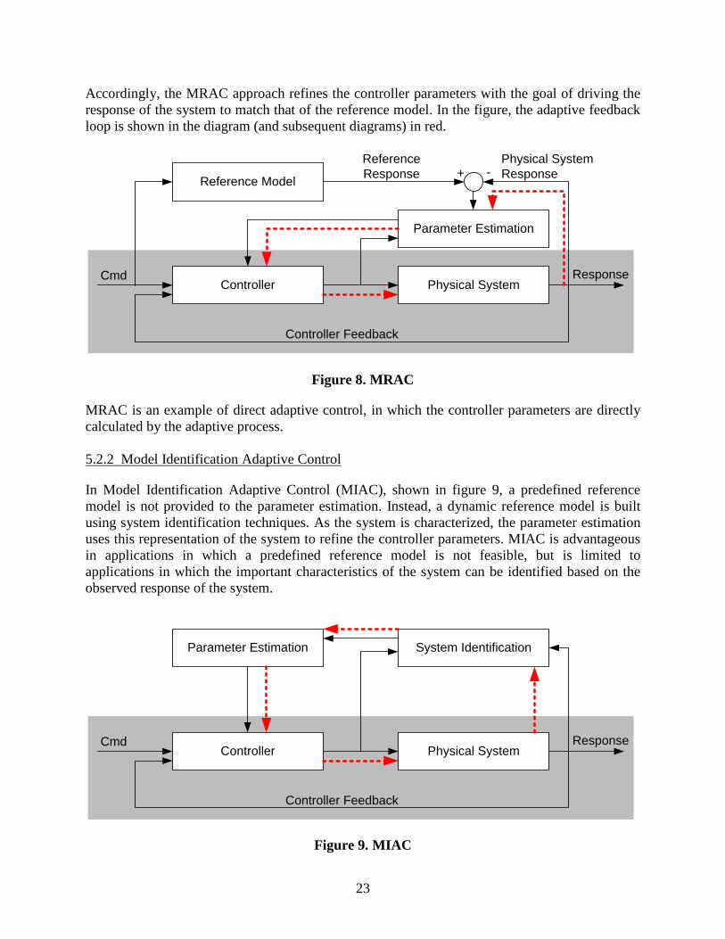
Accordingly, the MRAC approach refines the controller parameters with the goal of driving the response of the system to match that of the reference model. In the figure, the adaptive feedback loop is shown in the diagram (and subsequent diagrams) in red.
Figure 8. MRAC
MRAC is an example of direct adaptive control, in which the controller parameters are directly calculated by the adaptive process. 5.2.2 Model Identification Adaptive Control
In Model Identification Adaptive Control (MIAC), shown in figure 9, a predefined reference model is not provided to the parameter estimation. Instead, a dynamic reference model is built using system identification techniques. As the system is characterized, the parameter estimation uses this representation of the system to refine the controller parameters. MIAC is advantageous in applications in which a predefined reference model is not feasible, but is limited to applications in which the important characteristics of the system can be identified based on the observed response of the system.
Figure 9. MIAC
Reference Model
Controller
Parameter Estimation
Physical System
Reference Response
Cmd Response
Controller Feedback
+ -Physical System Response
Parameter Estimation
Controller
System Identification
Physical SystemCmd Response
Controller Feedback
23
MIAC is an example of indirect adaptive control, in which the adaptive mechanism provides estimated system parameters to a separate process that calculates the controller parameters. For example, the adaptive system identification process may refine estimates of aerodynamic coefficients, which are subsequently used in the parameter estimation process to calculate controller gains and filter coefficients.
5.2.3 Model-Free Adaptive Control
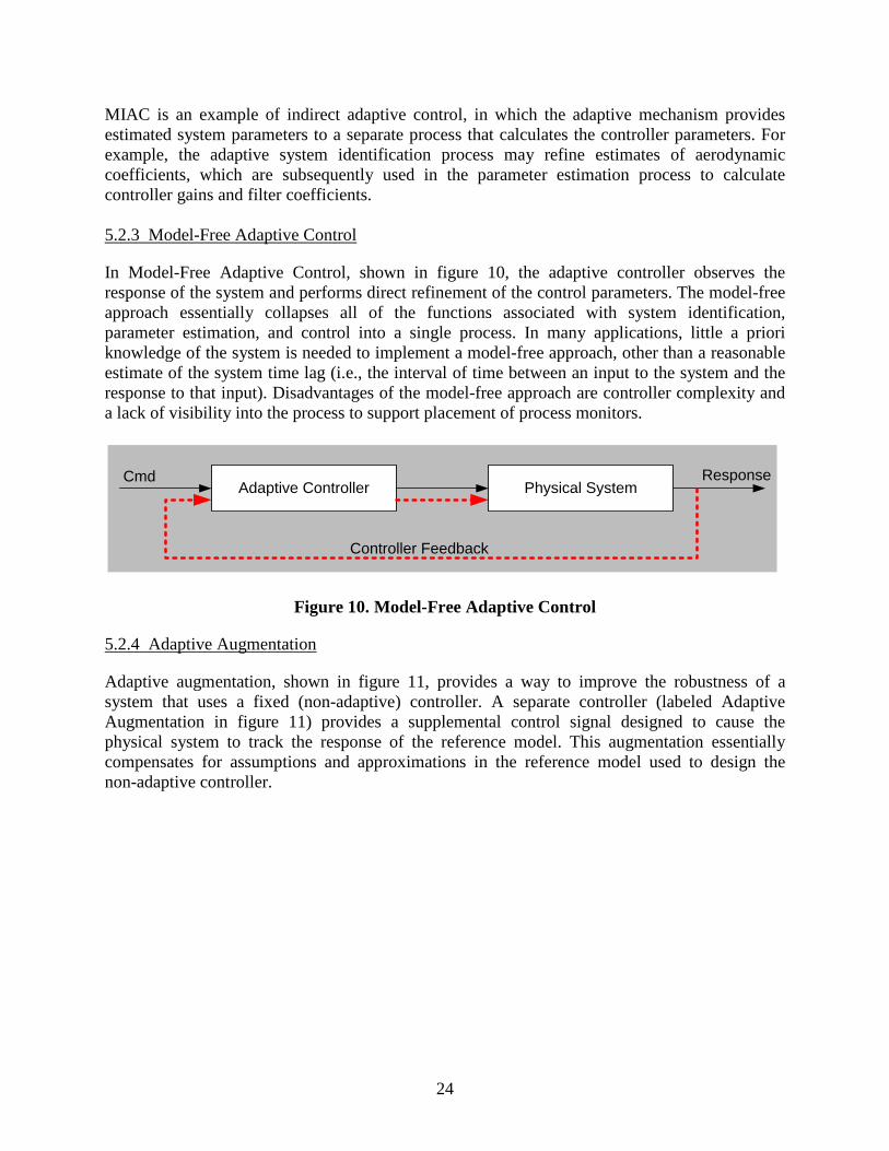
In Model-Free Adaptive Control, shown in figure 10, the adaptive controller observes the response of the system and performs direct refinement of the control parameters. The model-free approach essentially collapses all of the functions associated with system identification, parameter estimation, and control into a single process. In many applications, little a priori knowledge of the system is needed to implement a model-free approach, other than a reasonable estimate of the system time lag (i.e., the interval of time between an input to the system and the response to that input). Disadvantages of the model-free approach are controller complexity and a lack of visibility into the process to support placement of process monitors.
Figure 10. Model-Free Adaptive Control
5.2.4 Adaptive Augmentation
Adaptive augmentation, shown in figure 11, provides a way to improve the robustness of a system that uses a fixed (non-adaptive) controller. A separate controller (labeled Adaptive Augmentation in figure 11) provides a supplemental control signal designed to cause the physical system to track the response of the reference model. This augmentation essentially compensates for assumptions and approximations in the reference model used to design the non-adaptive controller.
Adaptive Controller Physical SystemCmd Response
Controller Feedback
24
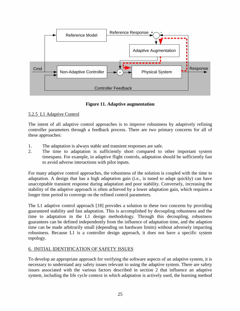
Figure 11. Adaptive augmentation
5.2.5 L1 Adaptive Control
The intent of all adaptive control approaches is to improve robustness by adaptively refining controller parameters through a feedback process. There are two primary concerns for all of these approaches: 1. The adaptation is always stable and transient responses are safe. 2. The time to adaptation is sufficiently short compared to other important system
timespans. For example, in adaptive flight controls, adaptation should be sufficiently fast to avoid adverse interactions with pilot inputs.
For many adaptive control approaches, the robustness of the solution is coupled with the time to adaptation. A design that has a high adaptation gain (i.e., is tuned to adapt quickly) can have unacceptable transient response during adaptation and poor stability. Conversely, increasing the stability of the adaptive approach is often achieved by a lower adaptation gain, which requires a longer time period to converge on the refined control parameters. The L1 adaptive control approach [18] provides a solution to these two concerns by providing guaranteed stability and fast adaptation. This is accomplished by decoupling robustness and the time to adaptation in the L1 design methodology. Through this decoupling, robustness guarantees can be defined independently from the influence of adaptation time, and the adaption time can be made arbitrarily small (depending on hardware limits) without adversely impacting robustness. Because L1 is a controller design approach, it does not have a specific system topology. 6. INITIAL IDENTIFICATION OF SAFETY ISSUES
To develop an appropriate approach for verifying the software aspects of an adaptive system, it is necessary to understand any safety issues relevant to using the adaptive system. There are safety issues associated with the various factors described in section 2 that influence an adaptive system, including the life cycle context in which adaptation is actively used, the learning method
Adaptive Augmentation
Non-Adaptive Controller Physical SystemCmd Response
Controller Feedback
+
Reference ModelReference Response + -
25
used, and the role that the adaptation plays in the overall system function. This section discusses safety issues identified during Phase 1, with respect to each of these factors. 6.1 IMPACT OF LIFE CYCLE CONTEXT ON SAFETY
A primary distinction with respect to safety is between adaptive systems that are adaptive only for development, and those that are intended to remain adaptive in operation. Because the design associated with adaptive systems used only for development is fixed, the safety concerns for these are similar to what would be appropriate for any other fixed design. However, there are some characteristics of the adaptive algorithm that should be addressed from a safety perspective. Using the fuel measurement system example, the NN was trained using data provided by a high-fidelity model relating sensor readings to fuel level. The trained network shows good agreement with the training data and verification data. Though the network was then fixed, it still contained nonlinearities that needed to be evaluated analytically to show that they would not present a threat to the safe operation of the aircraft by providing spurious fuel measurement readings into the system. An analytical approach was devised that showed mathematically that nonlinearities between test points were bounded and well behaved, demonstrating that network nonlinearities would not result in spurious fuel measurement. Based on this example, the following safety considerations were identified for the use of an adaptive approach in which the system is fixed in operation: • The integrity of the training data should be substantiated. In particular, the training data
should provide a complete and correct representation of the intended behavior of the adaptive system.
• Verification data that is independent of the training data should be provided to demonstrate that the network has converged to an acceptable solution.
• Any nonlinear characteristics in the resulting system should be shown not to adversely impact system safety. This argument should address the entire operational input space of the adaptive system, not just specific points covered by training or verification data.
• The means for continuing to update the solution should be shown to be disabled so that the system cannot inadvertently become adaptive in operations.
• Other safety concerns that may be associated with the use of similar conventional systems for the specific application area should be addressed.
For applications that adapt in operation, the safety considerations are predicated on the type of application and the safety concerns associated with the specific adaptive approach. These safety considerations are addressed in section 6.2. 6.2 IMPACT OF THE ROLE OF ADAPTATION ON SAFETY
Adaptation could be used in various types of applications that would be relevant to NextGen or to airborne systems. Additional types may be identified as this analysis progresses, or the definition of additional sub-types may prove beneficial in the future. For each type of
26
application, the role that the adaptation would play is addressed and safety considerations are listed.
6.2.1 Monitoring
Adaptive approaches that use statistical analysis for classification and clustering can be used for monitoring applications, such as vehicle or system health monitoring. If used in a batch environment, a monitoring technique can review a pre-recorded data set to look for anomalies and trends that, otherwise, may not be evident from inspection. If used in a real-time context, these techniques can assess current data in light of the data history to produce insight for situational awareness or vehicle health.
6.2.1.1 Safety Considerations
Adaptive approaches for system monitoring are typically used in an offline setting. Any insight gained from these analyses can be subject to verification before an action, typically manual, is taken. The use of these techniques in a real-time setting is a current research topic. Certainly the risk of either false-positive or false-negative indications resulting from these techniques would need to be carefully evaluated before any use could be proposed for a safety-critical environment, particularly if the indication triggered an automated response.
6.2.2 Parameter Estimation for Performance/Efficiency
An adaptive approach can be used to refine estimates of a parameter or set of parameters that are related to performance. For conventional systems, performance models are often deliberately conservative, and online estimation of related parameters may provide benefits in terms of efficiency or performance. Regression analysis is often used for parameter estimation.
6.2.1.2 Safety Considerations
Parameter estimation may represent minimal safety concerns if certain considerations can be addressed. The primary consideration is establishing a safe range from which the adaptive approach can select a parameter value. Excursions outside this bound would indicate that the adaptive approach is nonconvergent, and a monitor would provide the means for reverting to a conventional approach, such as a fixed value that represents the midpoint of the allowable parameter range. Analysis would be necessary to show that the discontinuous jump from the previous out-of-range value to the midpoint value does not introduce an unsafe transient.
6.2.3 Parameter Estimation for Robustness
The previous discussion addresses parameter estimation to improve performance/efficiency. Parameter estimation can also be used in a controls application to improve the robustness of the controller. For cases such as indirect adaptive control, control parameters may be calculated from other system parameters, such as airspeed. In this situation, the control law itself is not adaptive, but parameters provided to it, from which it calculates its control parameters, are determined using an adaptive approach. The use of indirect adaptive control is likely to result in a more robust control law for the current operational conditions, because adaptive estimation is likely to
27

provide more accurate estimations of parameter values than could be provided through conventional means (such as with a priori analysis or a table lookup value). 6.2.1.3 Safety Considerations
The safety implications for parameter estimations that are used in indirect adaptive control applications may be greater than those associated with estimation used for performance/efficiency improvements. Errors in estimation, even if the estimates are within the tolerance boundaries, now imply a reduction in control system robustness, rather than merely a loss of performance or efficiency. Additionally, a discontinuous jump when the fallback is invoked may result in an unsafe control system transient. 6.2.4 Control Reconfiguration Parameter estimation for direct adaptive control generates refined values for the control system parameters directly, based on the response of the closed loop system. Direct adaptive controls may provide the greatest benefit in terms of robustness and may provide the only means to retain stability in situations in which changes in the system or the operational environment deviate substantially from those assumed when the control law was developed. 6.2.1.4 Safety Considerations
It may be infeasible to establish parameter estimate bounds and a baseline for reversion if the direct adaptive approach fails. Accordingly, there may not be means for providing a backup control system that can be invoked if the adaptive approach becomes unstable. The viability of an adaptive control system may then rest completely on the strength of the analytical evidence that can be established prior to deployment. Certain adaptive control techniques, such as L-1 adaptive control, provide guarantees regarding convergence and other characteristics related to the robustness. Consequently, safety considerations associated with adaptive control reconfiguration is largely tied to the type of control architecture used and the specific adaptive technology used within that architecture. 6.2.5 Planning Statistical analysis for optimization combined with reinforcement learning may be applicable to applications involving planning or trajectory analysis. Similar to the discussion for monitoring, it is envisioned that optimization using reinforcement learning could be used in a non-real-time setting to generate plans or optimized trajectories that could then be verified before being acted upon. It is possible, however, that these techniques could also be used in a real-time environment to perform in situ trajectory revisions. 6.2.1.5 Safety Considerations
Planning that uses an adaptive approach is typically performed in an offline setting. Results from these adaptive techniques can be subject to verification before an action (typically manual) is taken. The use of trajectory optimization or other planning in a real-time context would necessitate the use of monitors to ensure that no safety or operational constraints are violated by
28
the results and that a suitable fallback is provided in case the adaptive approach is non-convergent. 6.3 SAFETY CONCERNS FOR ADAPTIVE ALGORITHMS
Safety concerns can differ depending on the type of adaptive algorithm or technique used. This analysis is ongoing and, when complete, can be overlaid on the safety considerations associated with specific applications to develop a composite picture that includes safety considerations for a particular adaptive technology used for a particular application. 6.3.1 NNS
Safety considerations for NNs are split between static (non-adaptive in operation) and dynamic NNs, including dynamically growing networks, in which additional neurons may be inserted during operations: • In static NNs, unsafe nonlinear network response can occur during operation in a region
of the input space that was not covered by verification. • Dynamic NNs have safety concerns including:
- Feedback data that could contain a substantial amount of noise that adversely impacts convergence of the adaptation.
- Schemes that dynamically insert additional neurons into the network. A failure
condition (FC) may result if this growth is unbounded to the point that it impacts convergence/computational resources because there are too many nodes to process in the time required.
- Adaptation that fails to converge quickly enough to support continued safe
operations. 6.3.2 Genetic Algorithms
As discussed in section 4.2, genetic algorithms involve the stochastic generation of populations of candidate solutions that compete in an evolutionary process. The benefit of the technique is to propose novel candidate solutions and would likely be applicable primarily to a development environment. Candidate solutions proposed through the use of genetic algorithms would be subject to verification to ensure that they do not present safety concerns. Because it is not certain that solutions provided by genetic algorithms are linear, their verification may be similar to what would be performed on static NNs or other nonlinear algorithms.
29
6.3.3 Reflection/Autonomic Computing
This technology can adjust the structure of the computer program at runtime and, therefore, the safety considerations associated with the technology can extend to reallocation of computational resources. Relevant safety considerations include:
• Safety impacts due to the reallocation of resources.• Changes in the operating system schedule that may affect hard real-time deadlines.• Resources allocated to increase performance that could adversely affect components.
6.3.4 Adaptive Controls
A number of representative adaptive control architectures are discussed in section 5. In some instances, a specific adaptive technology, such as an NN, provides the adaptivity (such as estimating an indirect parameter for MRAC). In other instances, the technology itself defines the architecture, as is the case with L-1 adaptive control.
Safety considerations for adaptive control depend not only on the type of control architecture used but also on the characteristics of the system under control. Generally, systems with slowly varying system characteristics may provide less concern for the application of adaptive controls than a system with rapidly varying or discontinuous dynamics. In addition, issues presented in section 5 regarding controllability and observability are issues for any adaptive control approach.
In summary, safety considerations for adaptive controllers result from the combined contributions of the specific adaptive control technology, the architecture in which it is used, and the characteristics of the system to which the adaptive control scheme is applied.
7. INITIAL PHASE 2 ACTIVITIES
Though the Phase 1 effort was aimed at identifying foundational aspects essential to assessing the assurance needs for adaptive systems, Phase 2 worked to condense that information to understand what specific requirements, especially at the software level, are needed to ensure the safe use of adaptive systems. Because the work in Phase 2 was not done by those who worked on Phase 1, initial Phase 2 activities started with a review of the Phase 1 results and final report [19] and independent examination of the characteristics and architecture of several basic types of adaptive systems.
An adaptive system typically incorporates a reference model of the desired response and a learning mechanism that adjusts the control parameters in response to measured changes in the external environment. The control objective is to adjust parameters so that the actual performance matches the desired one. The learning mechanism may take several forms, such as NN, reflection/autonomic (dynamic code assignment or self-modifying code), and genetic update (random mutation and fitness selection), as described in section 4.
Figure 12 shows a useful taxonomy of the essential attributes of adaptive systems. As figure 12 shows, there is tremendous diversity among different types of adaptive systems, making generic assessment of software assurance requirements infeasible. Consequently, the Phase 2 efforts
30
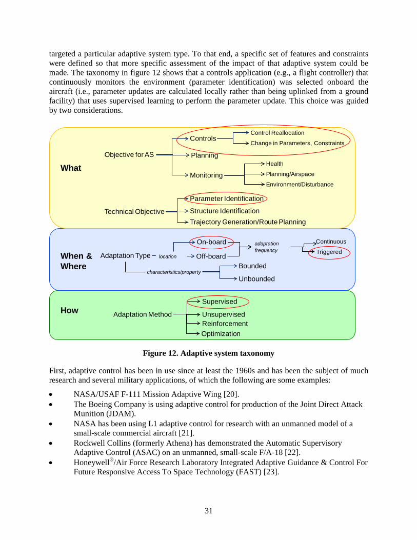
targeted a particular adaptive system type. To that end, a specific set of features and constraints were defined so that more specific assessment of the impact of that adaptive system could be made. The taxonomy in figure 12 shows that a controls application (e.g., a flight controller) that continuously monitors the environment (parameter identification) was selected onboard the aircraft (i.e., parameter updates are calculated locally rather than being uplinked from a ground facility) that uses supervised learning to perform the parameter update. This choice was guided by two considerations.
Figure 12. Adaptive system taxonomy
First, adaptive control has been in use since at least the 1960s and has been the subject of much research and several military applications, of which the following are some examples:
• NASA/USAF F-111 Mission Adaptive Wing [20]. • The Boeing Company is using adaptive control for production of the Joint Direct Attack
Munition (JDAM). • NASA has been using L1 adaptive control for research with an unmanned model of a
small-scale commercial aircraft [21]. • Rockwell Collins (formerly Athena) has demonstrated the Automatic Supervisory
Adaptive Control (ASAC) on an unmanned, small-scale F/A-18 [22]. • Honeywell®/Air Force Research Laboratory Integrated Adaptive Guidance & Control For
Future Responsive Access To Space Technology (FAST) [23].
Objective for AS
Adaptation Type
Technical Objective
Controls
On-board
Off-board
Monitoring
Health
Planning/Airspace
Environment/Disturbance
Control Reallocation
Parameter Identification
Structure IdentificationTrajectory Generation/Route Planning
Change in Parameters, Constraints
Adaptation Method
Supervised
UnsupervisedReinforcement
Bounded
Unbounded
Continuous
Triggered
Planning
What
When &Where
How
Optimization
characteristics/property
location
adaptation frequency
31

These types of adaptive controllers have not been used in any commercial aircraft. Second, the research team tentatively concluded that, to ensure the safety of an airborne adaptive system, it would: (1) be necessary to impose some system-level features and constraints, and (2) be of a type that could be feasibly and accurately represented by a computer model of a type amenable to automated analysis. These self-imposed requirements excluded the genetic algorithm and reflection/autonomic types of learning because they appeared to present extreme modeling difficulty. Controllers of the gain scheduled-type were not considered because the adaptation is limited to a few predetermined states and can therefore be verified using the standard methods of DO-178B/C. Similarly, an adaptive system that is pretrained offline and remains in a fixed configuration was not considered. To focus the analysis, a representative adaptive system architecture exemplar was constructed that generalizes the above examples and meets the imposed requirements to use in analysis of verifiability per DO-178B/C (figure 13 shows a block diagram).
Figure 13. Example of flight control architecture
This is a triggered system that uses an expected response model to update its operating parameters. The updated values are used when triggered by a signal (e.g., by pilot command or vehicle health management [VHM] system acting as an observer of various related aircraft components such as sensors, hydraulics, actuators, control surfaces, etc.) or the occurrence of a failure or off-nominal condition. The architecture otherwise remains in a fixed/static configuration. At the outset, two major safety requirements were considered for this controller: (1) that parameter adjustment be constrained to predetermined ranges that guarantee stability and controllability (e.g., in the Lyapunov criteria sense), and (2) that the control error signal converges asymptotically to approximately zero, within an arbitrarily small bound, infinite time.
System Identification
32

These seem to be essential features of a certifiable flight control system whether adaptive or not, though they may be challenging requirements, depending on the adaptive algorithm.
To determine the applicability of the DO-178B/C objectives to this adaptive controller, it is helpful to review the current certification framework and the recent changes it has undergone. Section 8 describes the certification methodology and framework in the current CFR, associated advisory materials, and industry standards.
8. CURRENT CERTIFICATION GUIDANCE AND STANDARDS
It is helpful to discuss the current certification framework to determine whether or not adaptive systems could be certified with or without changes and what those changes should be if required.
This framework is built around Title 14 CFR. Figure 14 shows the general process flow and the applicable de facto standards of current certification practice. These standards relate to: (1) system development, (2) safety assessment, and (3) design assurance of system hardware and software. In the interest of focusing on the key steps, details of all activities and deliverables to be fully compliant are not shown, however, they can be found within the referenced documents . The aim here is to give an overview and not a full descriptive narrative. DO-254 [24] is not discussed because this is not within the scope of the original task and is limited in application to programmable devices and not to hardware generally [25, 26]. Similarly, SAE ARP-5150 [27] provides guidance for assessing ongoing safety during commercial operations, but this aspect will not be discussed in this report.
33
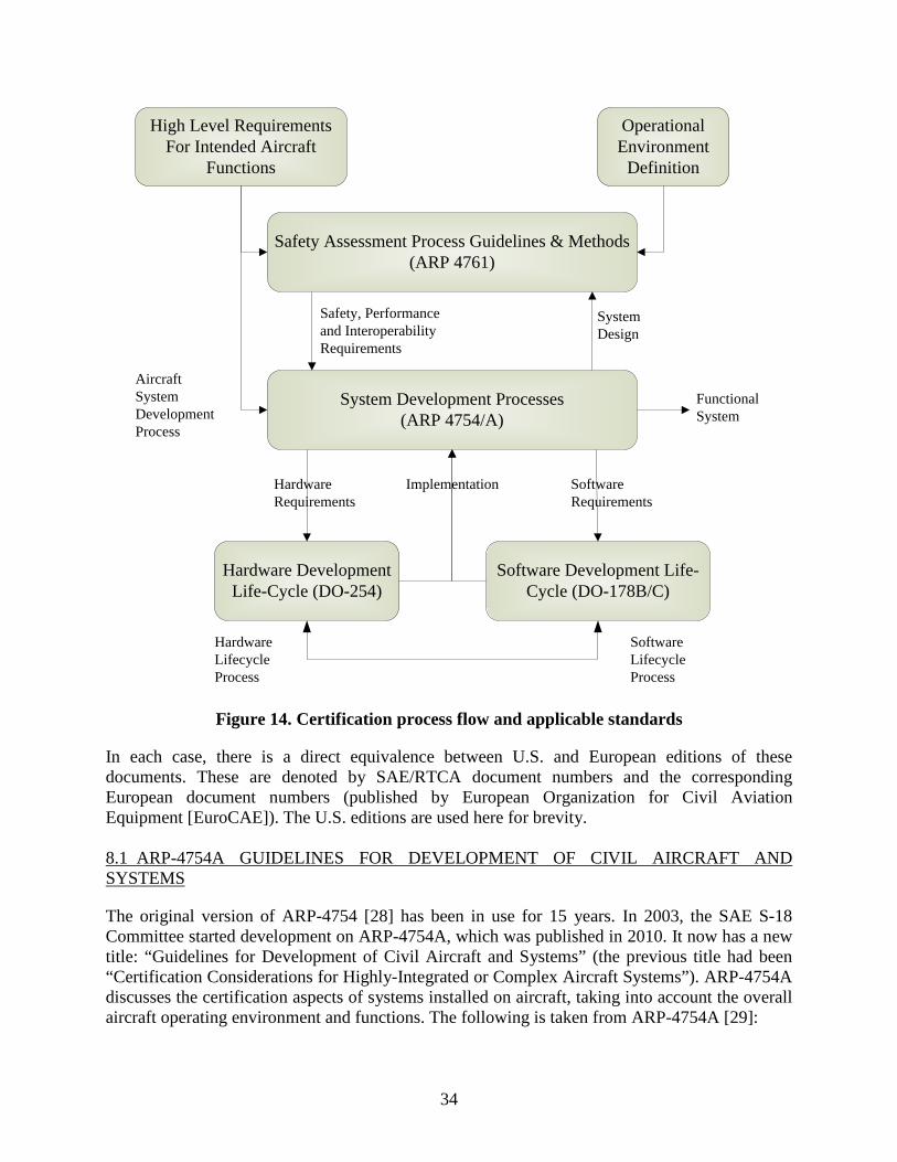
Figure 14. Certification process flow and applicable standards
In each case, there is a direct equivalence between U.S. and European editions of these documents. These are denoted by SAE/RTCA document numbers and the corresponding European document numbers (published by European Organization for Civil Aviation Equipment [EuroCAE]). The U.S. editions are used here for brevity. 8.1 ARP-4754A GUIDELINES FOR DEVELOPMENT OF CIVIL AIRCRAFT AND SYSTEMS
The original version of ARP-4754 [28] has been in use for 15 years. In 2003, the SAE S-18 Committee started development on ARP-4754A, which was published in 2010. It now has a new title: “Guidelines for Development of Civil Aircraft and Systems” (the previous title had been “Certification Considerations for Highly-Integrated or Complex Aircraft Systems”). ARP-4754A discusses the certification aspects of systems installed on aircraft, taking into account the overall aircraft operating environment and functions. The following is taken from ARP-4754A [29]:
Safety Assessment Process Guidelines & Methods (ARP 4761)
System Development Processes(ARP 4754/A)
Hardware Development Life-Cycle (DO-254)
Software Development Life-Cycle (DO-178B/C)
High Level RequirementsFor Intended Aircraft
Functions
Aircraft System Development Process
Hardware Lifecycle Process
Software Lifecycle Process
Operational Environment
Definition
Safety, Performance and Interoperability Requirements
System Design
Functional System
Hardware Requirements
Software Requirements
Implementation
34
This document discusses the development of aircraft systems taking into account the overall aircraft operating environment and functions. This includes validation of requirements and verification of the design implementation for certification and product assurance. It provides practices for showing compliance with the regulations and serves to assist a company in developing and meeting its own internal standards by considering the guidelines herein. The guidelines in this document were developed in the context of 14CFR Part 25 and European Aviation Safety Agency (EASA) Certification Specification (CS) CS-25. It may be applicable to other regulations, such as Parts 23, 27, 29, 33, and 35 (CS-23, CS-27, CS-29, CS-E, CS-P). This document addresses the development cycle for aircraft and systems that implement aircraft functions. It does not include specific coverage of detailed software or electronic hardware development, safety assessment processes, in-service safety activities, aircraft structural development nor does it address the development of the Master Minimum Equipment List (MMEL) or Configuration Deviation List (CDL). More detailed coverage of the software aspects of development are found in RTCA document DO-178B, “Software Considerations in Airborne Systems and Equipment Certification” and its EUROCAE counterpart, ED-12B. Coverage of electronic hardware aspects of development are found in RTCA document DO-254/EUROCAE ED-80, “Design Assurance Guidance for Airborne Electronic Hardware”. Design guidance and certification considerations for integrated modular avionics are found in appropriate RTCA/EUROCAE document DO-297/ED-124. Methodologies for safety assessment processes are outlined in SAE document ARP4761, “Guidelines and Methods for Conducting the Safety Assessment Process on Civil Airborne Systems and Equipment”. Details for in-service safety assessment are found in ARP5150, “Safety Assessment of Transport Airplanes In Commercial Service” and ARP5151 Safety Assessment of General Aviation Airplanes and Rotorcraft In Commercial Service. “Post-certification activities (modification to certificated product) are covered in section 6 of this document. The regulations and processes used to develop and approve the MMEL vary throughout the world. Guidance for the development of the MMEL should be sought from the local airworthiness authority.”
Table 2 shows the means by which ARP-4754A may be invoked for a particular certification project. ARP-4754A guidance may also be applicable to aircraft equipment certified to other CFR parts, such as Parts 23, 27, 29, and 33, so for brevity only Part 25 will be considered in the discussion. In this table, the term “invocation/policy” means that the referenced document is recognized by the regulator as an acceptable means of compliance with the applicable CFR Part.
35
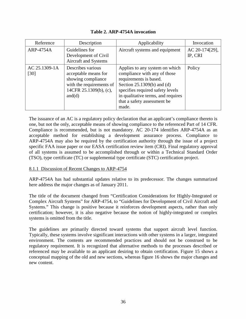
Table 2. ARP-4754A invocation
Reference Description Applicability Invocation ARP-4754A Guidelines for
Development of Civil Aircraft and Systems
Aircraft systems and equipment AC 20-174[29], IP, CRI
AC 25.1309-1A [30]
Describes various acceptable means for showing compliance with the requirements of 14CFR 25.1309(b), (c), and(d)
Applies to any system on which compliance with any of those requirements is based. Section 25.1309(b) and (d) specifies required safety levels in qualitative terms, and requires that a safety assessment be made.
Policy
The issuance of an AC is a regulatory policy declaration that an applicant’s compliance thereto is one, but not the only, acceptable means of showing compliance to the referenced Part of 14 CFR. Compliance is recommended, but is not mandatory. AC 20-174 identifies ARP-4754A as an acceptable method for establishing a development assurance process. Compliance to ARP-4754A may also be required by the certification authority through the issue of a project specific FAA issue paper or our EASA certification review item (CRI). Final regulatory approval of all systems is assumed to be accomplished through or within a Technical Standard Order (TSO), type certificate (TC) or supplemental type certificate (STC) certification project.
8.1.1 Discussion of Recent Changes to ARP-4754
ARP-4754A has had substantial updates relative to its predecessor. The changes summarized here address the major changes as of January 2011.
The title of the document changed from “Certification Considerations for Highly-Integrated or Complex Aircraft Systems” for ARP-4754, to “Guidelines for Development of Civil Aircraft and Systems.” This change is positive because it reinforces development aspects, rather than only certification; however, it is also negative because the notion of highly-integrated or complex systems is omitted from the title.
The guidelines are primarily directed toward systems that support aircraft level function. Typically, these systems involve significant interactions with other systems in a larger, integrated environment. The contents are recommended practices and should not be construed to be regulatory requirement. It is recognized that alternative methods to the processes described or referenced may be available to an applicant desiring to obtain certification. Figure 15 shows a conceptual mapping of the old and new sections, whereas figure 16 shows the major changes and new content.
36
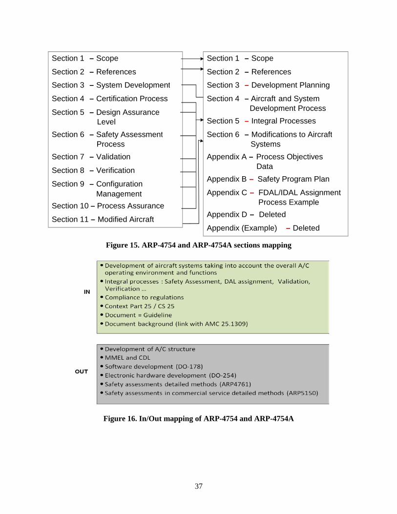
Figure 15. ARP-4754 and ARP-4754A sections mapping
Figure 16. In/Out mapping of ARP-4754 and ARP-4754A
Section 1
– Scope Section 2
– References
Section 3
– System Development Section 4
– Certification Process
Section 5
– Design Assurance Level Section 6
– Safety Assessment
Process Section 7
– Validation
Section 8
– Verification
Section 9
– Configuration Management
Section 10
– Process Assurance
Section 11
– Modified Aircraft
Section 1
– Scope Section 2
– References
Section 3
– Development Planning
Section 4
– Aircraft and System Development Process
Section 5
– Integral Processes
Section 6
– Modifications to Aircraft Systems
Appendix A – Process Objectives Data
Appendix B
– Safety Program Plan
Appendix C
– FDAL/IDAL Assignment
Appendix D
– Deleted
Appendix (Example)
– Deleted
Process Example
37

8.1.2 Identified Textual Changes Within ARP-4754A
8.1.2.1 Section 1—Scope
• A paragraph was deleted with reference to the precedence of this document in the event of conflict between the text of this document and the text of DO-178B.
• All the information concerning “highly-integrated” or “complex systems” was deleted. 8.1.2.2 Section 2—References
• Applicable documents → Relationship between American/European standards. • Definitions. • Abbreviations and acronyms were added. 8.1.2.3 Section 3—Development Planning
• Life cycle process checkpoints and reviews were added. • Maturity expectations. • Transition criteria (i.e., life cycle process checkpoints and reviews, which are aligned
with program phases and gates). • Management of deviations from plans. 8.1.2.4 Section 4—Aircraft and System Development Process
• Identification of aircraft-level functions, function requirements and function interfaces • Relationship between requirement levels, functional development assurance level
(FDAL) and item development assurance level (IDAL) • The objectives for accomplishment of FDAL and IDAL (i.e., ARP4754A, Appendix A,
DO-254/ED-80, and DO-178B/ED-12) 8.1.2.5 Section 5.1—Safety Assessment
• Safety case/Safety synthesis. • Safety program plan. • Preliminary Aircraft Safety Assessment. • Aircraft Safety Assessment. 8.1.2.6 Section 5.2—Design Assurance Level Assignment
• Design Assurance Level (DAL) assignment based on FC severity classification and independence attributes (no longer based on type of architectures).
• Two different DALs: FDAL that apply to function requirement development and IDAL that apply to item (hardware/software) development.
• Concept of Functional Failure Sets.
38

• New Table 5-2, “Development Assurance Level Assignment to Members of a Functional Failure Set,” with two assignment options.
• FDAL assignment taking credit for external events. 8.1.2.7 Section 5.3—Requirements Capture
• Re-use of existing certified systems and items. The requirements to which the system or item was certified should be validated, according to the new application, and modified as necessary.
• Deriving safety-related requirements from the safety analyses. 8.1.2.8 Section 5.4—Requirements Validation
• Definition of correctness and completeness improved. • Validation rigor improved with the concept of independence in the validation process. • The application of independence in the validation process is dependent on the DAL. • The validation plan should include a description of the validation activities to which
independence is applied. • Independent review of requirement data and supporting rationale. • The reviews should be documented, including the review participants and their roles. 8.1.2.9 Section 5.5—Implementation Verification
• Identification of key verification activities and sequence of any dependent activities. • Identification of the roles and responsibilities associated with conducting the verification
activities and a description of independence between design and verification activities.
8.1.2.10 Section 5.6—Configuration Management
• Two system control categories (see ARP-4754A Tables 5-6). 8.1.2.11 Section 5.7—Process Assurance
• The process assurance activities described are not intended to imply or impose specific organizational structures or responsibilities. However, process assurance should have a level of independence from the development process.
8.1.2.12 Section 5.8—Certification Process
• There may be a single certification plan for the project or a top-level plan for the aircraft and a set of related plans for each of the aircraft systems.
• Early coordination and approval of the plan is strongly encouraged.
39
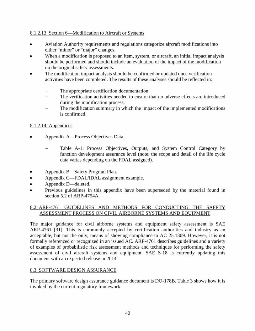
8.1.2.13 Section 6—Modification to Aircraft or Systems
• Aviation Authority requirements and regulations categorize aircraft modifications intoeither “minor” or “major” changes.
• When a modification is proposed to an item, system, or aircraft, an initial impact analysisshould be performed and should include an evaluation of the impact of the modificationon the original safety assessments.
• The modification impact analysis should be confirmed or updated once verificationactivities have been completed. The results of these analyses should be reflected in:
- The appropriate certification documentation. - The verification activities needed to ensure that no adverse effects are introduced
during the modification process. - The modification summary in which the impact of the implemented modifications
is confirmed.
8.1.2.14 Appendices
• Appendix A—Process Objectives Data.
- Table A-1: Process Objectives, Outputs, and System Control Category by function development assurance level (note: the scope and detail of the life cycle data varies depending on the FDAL assigned).
• Appendix B—Safety Program Plan.• Appendix C—FDAL/IDAL assignment example.• Appendix D—deleted.• Previous guidelines in this appendix have been superseded by the material found in
section 5.2 of ARP-4754A.
8.2 ARP-4761 GUIDELINES AND METHODS FOR CONDUCTING THE SAFETY ASSESSMENT PROCESS ON CIVIL AIRBORNE SYSTEMS AND EQUIPMENT
The major guidance for civil airborne systems and equipment safety assessment is SAE ARP-4761 [31]. This is commonly accepted by certification authorities and industry as an acceptable, but not the only, means of showing compliance to AC 25.1309. However, it is not formally referenced or recognized in an issued AC. ARP-4761 describes guidelines and a variety of examples of probabilistic risk assessment methods and techniques for performing the safety assessment of civil aircraft systems and equipment. SAE S-18 is currently updating this document with an expected release in 2014.
8.3 SOFTWARE DESIGN ASSURANCE
The primary software design assurance guidance document is DO-178B. Table 3 shows how it is invoked by the current regulatory framework.
40

Table 3. DO-178B invocation
Reference Description Applicability Invocation DO-178B Software
Considerations in Airborne Systems and Equipment Certification
Provides guidance for the production of software for airborne systems and equipment that performs its intended function with a level of confidence in safety that complies with airworthiness requirements
TSO, AC 20-115B
Order 8110.49, Change 1
Software Approval Guidelines
This order guides Aircraft Certification Service (AIR) field offices and Designated Engineering Representatives (DER) on how to apply RTCA/DO-178B, “Software Considerations in Airborne Systems and Equipment Certification,” for approving software used in airborne computers.
Policy
AC 20-115B Calls attention to RTCA DO-178B, “Software Considerations in Airborne Systems and Equipment Certification”
Calls attention to RTCA DO- 178B, “Software Considerations in Airborne Systems and Equipment Certification,” issued December 1992. It discusses how the document may be applied with FAA TSO, authorizations, TC, or supplemental type certification authorization (STC).
Policy
9. ADAPTIVE SYSTEM CERTIFICATION
This section discusses adaptive system certification in the context of the selected adaptive system controller example and the current certification framework described above. 9.1 CONCERNS REGARDING THE FEASIBILITY OF APPLYING DO-178B TO SOFTWARE DESIGN ASSURANCE OF ADAPTIVE SYSTEMS
All adaptive systems embody a learning subsystem of some type and an embedded model of the desired system performance. The learning subsystem changes the system operating parameters (e.g., control gain) in response to measurements taken on the external environment. The objective is that the actual performance closely matches the desired performance represented in the model. Non-adaptive (fixed configuration) systems assume that the external environment remains constant. The external environment includes the sensors providing the inputs and actuators operating control surfaces. There may be several parameters that adjust value over time through the learning function. These will, in general, be real-valued variables. This means that an adaptive system has an infinite set of possible parameter values even if the allowable range is constrained. This immediately leads to difficulties because it is infeasible to show by review, test, or conventional analysis that, in the implemented system, all system requirements are satisfied under all possible parameter values. Moreover, it is difficult to establish what the expected output from a test should be because the exact system state has evolved through
41
learning, is unobservable, and, therefore, unknown. These difficulties are explained at length in Jacklin [32, 33] and Schumann [34]. Therefore, one objective in this work is to find ways in which these difficulties can be overcome. 9.2 SUGGESTED APPROACH TO SOFTWARE DESIGN ASSURANCE OF ADAPTIVE SYSTEMS
In other works, such as reference 32, the problem has been asked in terms of what methods could be applied to comply with the assurance standards for software of DO-178B and what changes or additions to DO-178B would be necessary to permit compliance. Answers to these questions can best be arrived at by considering the methods by which validated, verifiable high-level requirements (HLRs) for adaptive systems can be written. With this approach, the software assurance problem becomes more tractable because DO-178B/C defines a process to verify that operational code meets the previously stated requirements, which are assumed to be correct and complete as provided by the systems and safety development processes. One premise of this work is that DO-178B alone cannot provide adequate software design assurance, but that DO-178C and its associated supplements offer a promising way to accomplish adequate software design assurance if they are preceded by rigorous system design activities that generate validated and verifiable design constraints and requirements. This is mainly because DO-178C and supplements offer a well-defined methodology to partially shift the software design assurance burden from test to analysis. Therefore, this research considered the means and methods by which an applicant can derive and validate a complete and consistent set of verifiable adaptive system requirements expressed in formal or mathematical terms with well-defined syntax and semantics that are amenable to modern analysis methods capable of providing a high level of design assurance. The following principles are asserted: • Software design assurance alone cannot ensure the safe application of adaptive systems. • System safety objectives must be defined and captured; these form the basis of an
unambiguous safety case. • The adaptive system must, by design, exhibit certain functional and safety properties to
ensure an acceptable level of safety. These properties need to be established and captured as part of the system requirements capture process.
• System-level validation of the system properties is necessary to ensure safe operation. This research suggests that some of the newer techniques incorporated in DO-178C and the associated supplements augmented by system-level considerations offer a possible means to overcome the difficulties of software design assurance for adaptive systems. More specifically, this research suggests that: • More reliance be placed on verification by analysis or simulation than on testing. • Multi-layered verification methods involving a judicious combination of testing, analysis,
and the simulation of models be used.
42
• Model-based design (MBD) techniques to capture system behavior in an analyzable form be used.
• Formal methods (FM) analysis techniques should be used because the learned state space is too broad for testing alone to provide adequate assurance and to predict expected test results.
• Improved system safety analysis techniques should be used to derive system safety properties and that those properties be expressed in mathematical notations that are amenable to verification by FM.
In addition, to make the verification effort manageable, techniques analogous to equivalency classes that subdivide the learned state space and structural coverage analysis that measures the verification completeness of the learned state space; both are needed to complete the approach. Currently, these techniques are not known. 9.3 SYSTEM-LEVEL APPROACHES TO THE CERTIFICATION OF ADAPTIVE SYSTEMS
Because of the difficulties of showing software design assurance of an adaptive system by following only the processes of DO-178C, this research concludes that, to ensure the safe use of adaptive systems, additional work must be accomplished at the system level with the imposition of certain constraints on the architecture and permitted adaptation. The constraints result in the construction of desired system safety properties and requirements that, when verified, ensure that the adaptive system provides an acceptable level of safety. The system HLR are therefore established as part of the system design and safety processes of ARP-4754A and ARP-4761 through the construction of system functional requirements and safety requirements. These properties must be written such that: • The system-level HLR fully express the necessary system properties. • They are verifiable by one of the means identified in DO-178C and the associated
supplements. The system properties are then verifiable by formal or other methods, so that objective proof of conformance can be established. In the analysis of problematic DO-178C objectives, this research makes use of the system properties that exist as a consequence of satisfying the safety objectives of the adaptive system. The definition of “requirement” given in ARP-4744A implies that requirements are valid only if there are means by which they can be verified. Therefore, the generation of requirements must be cognizant of the expected verification methods. Derived requirements, which develop throughout the development phase, should be redirected back to the system and safety processes for validation. This is necessarily an iterative process because there are no known stopping criteria that can reliably determine completeness.
43

9.4 DEFINING THE SYSTEM-LEVEL CHARACTERISTICS OF AN ADAPTIVE SYSTEM
To make the analysis more concrete, the example architecture diagram of the target (see figure 13) was analyzed to define some of its salient system-level characteristics in terms of thesystem-level design and safety objectives that we consider essential to enable compliance with the objectives of DO-178B/C and other airworthiness standards.
These characteristics are inputs to the requirements generation process to be followed by the implementation activity. In the analysis of challenging DO-178B/C objectives, the system properties that exist as a consequence of satisfying these adaptive system safety objectives were used. The first step in the process is to define the “system safety objectives” that must be satisfied as part of systems requirements, design, and verification and validation (V&V) processes (shown in table 4).
44
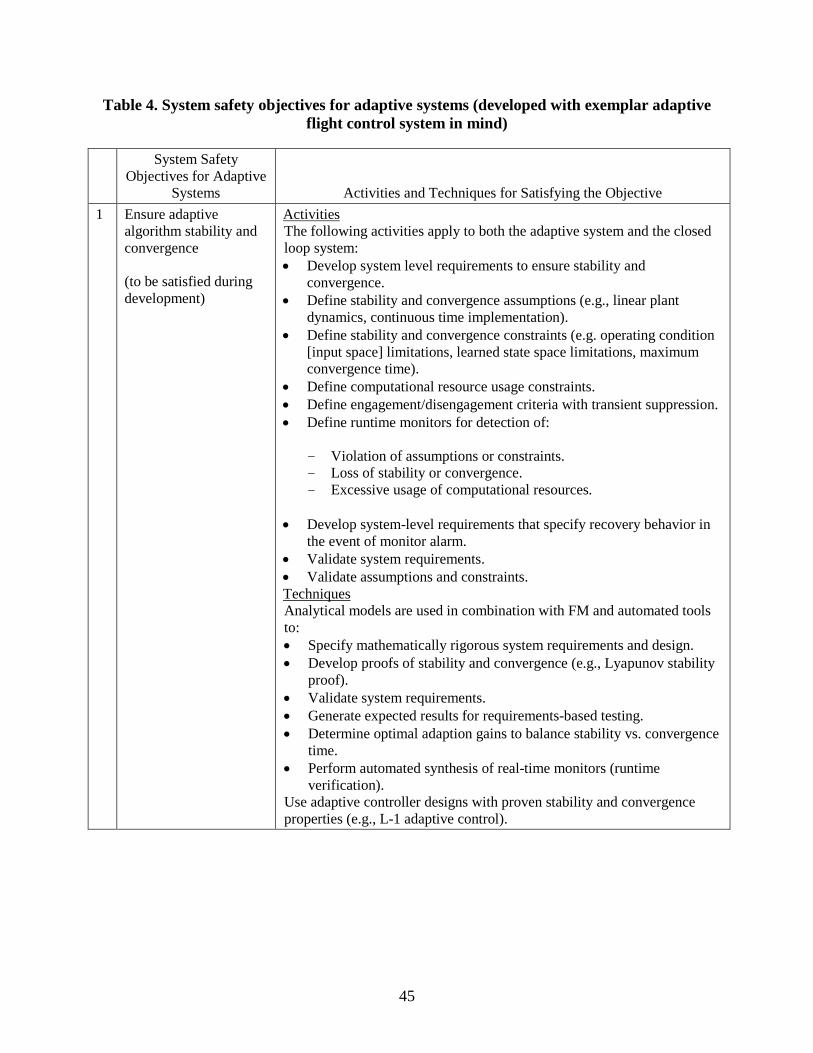
Table 4. System safety objectives for adaptive systems (developed with exemplar adaptive flight control system in mind)
System Safety Objectives for Adaptive
Systems Activities and Techniques for Satisfying the Objective 1 Ensure adaptive
algorithm stability and convergence (to be satisfied during development)
Activities The following activities apply to both the adaptive system and the closed loop system: • Develop system level requirements to ensure stability and
convergence. • Define stability and convergence assumptions (e.g., linear plant
dynamics, continuous time implementation). • Define stability and convergence constraints (e.g. operating condition
[input space] limitations, learned state space limitations, maximum convergence time).
• Define computational resource usage constraints. • Define engagement/disengagement criteria with transient suppression. • Define runtime monitors for detection of:
- Violation of assumptions or constraints. - Loss of stability or convergence. - Excessive usage of computational resources.
• Develop system-level requirements that specify recovery behavior in
the event of monitor alarm. • Validate system requirements. • Validate assumptions and constraints. Techniques Analytical models are used in combination with FM and automated tools to: • Specify mathematically rigorous system requirements and design. • Develop proofs of stability and convergence (e.g., Lyapunov stability
proof). • Validate system requirements. • Generate expected results for requirements-based testing. • Determine optimal adaption gains to balance stability vs. convergence
time. • Perform automated synthesis of real-time monitors (runtime
verification). Use adaptive controller designs with proven stability and convergence properties (e.g., L-1 adaptive control).
45
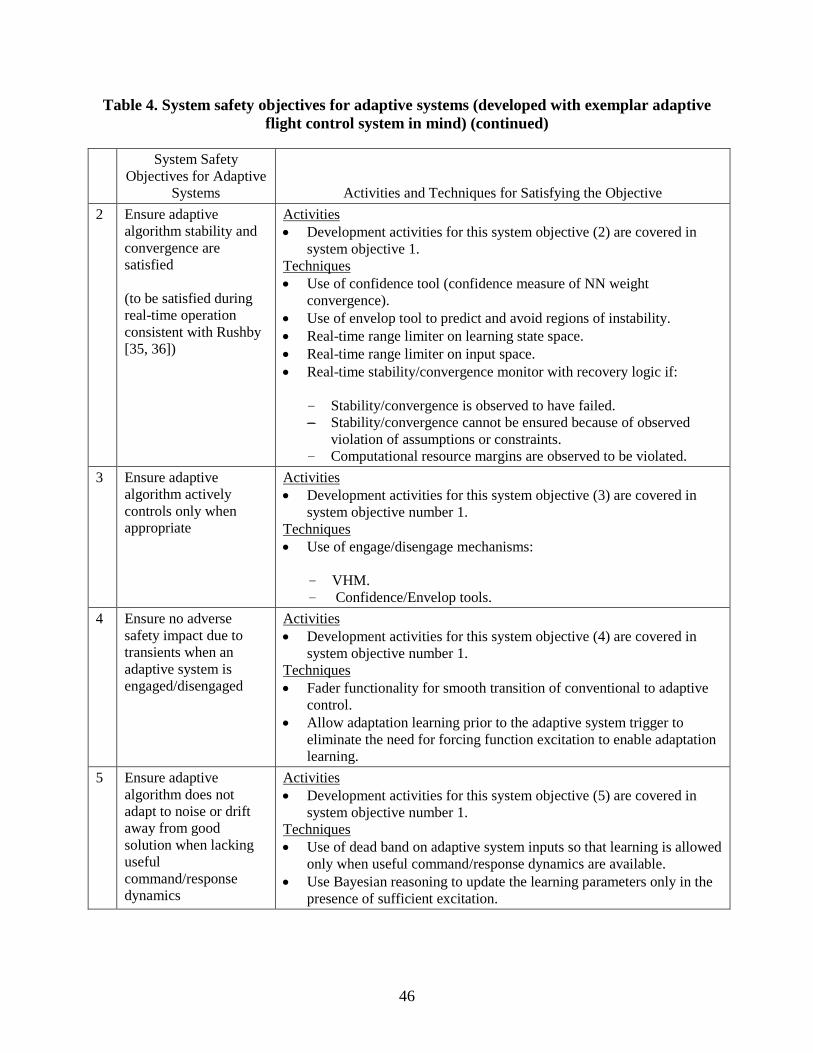
Table 4. System safety objectives for adaptive systems (developed with exemplar adaptive flight control system in mind) (continued)
System Safety Objectives for Adaptive
Systems Activities and Techniques for Satisfying the Objective 2 Ensure adaptive
algorithm stability and convergence are satisfied
(to be satisfied during real-time operation consistent with Rushby [35, 36])
Activities • Development activities for this system objective (2) are covered in
system objective 1.Techniques • Use of confidence tool (confidence measure of NN weight
convergence).• Use of envelop tool to predict and avoid regions of instability.• Real-time range limiter on learning state space.• Real-time range limiter on input space.• Real-time stability/convergence monitor with recovery logic if:
- Stability/convergence is observed to have failed.- Stability/convergence cannot be ensured because of observed
violation of assumptions or constraints. - Computational resource margins are observed to be violated.
3 Ensure adaptive algorithm actively controls only when appropriate
Activities • Development activities for this system objective (3) are covered in
system objective number 1.Techniques • Use of engage/disengage mechanisms:
- VHM.- Confidence/Envelop tools.
4 Ensure no adverse safety impact due to transients when an adaptive system is engaged/disengaged
Activities • Development activities for this system objective (4) are covered in
system objective number 1.Techniques • Fader functionality for smooth transition of conventional to adaptive
control.• Allow adaptation learning prior to the adaptive system trigger to
eliminate the need for forcing function excitation to enable adaptationlearning.
5 Ensure adaptive algorithm does not adapt to noise or drift away from good solution when lacking useful command/response dynamics
Activities • Development activities for this system objective (5) are covered in
system objective number 1.Techniques • Use of dead band on adaptive system inputs so that learning is allowed
only when useful command/response dynamics are available.• Use Bayesian reasoning to update the learning parameters only in the
presence of sufficient excitation.
46
The next step in the process is to work through all the objectives of DO-178B/C and, based on the principles described and on table 4, assign methods and techniques that would provide satisfaction of those objectives. The following methodology was used: • List DO-178B/C objectives that are difficult to meet for the example adaptive system
chosen. • Understand what the DO-178B/C objective is asking for and why it is more difficult to
meet for this example adaptive system versus a nonadaptive system. • List the functional and safety objectives of the system-level adaptive system. These
objectives will enter the requirements creation process of an implementation. • List the methods that could be used to provide the evidence necessary for the
system-level objective of the adaptive system. These steps have been followed for our example adaptive system and the results partially tabulated in appendix C. Because of resource constraints, table 4 is incomplete. The research team was unable to conclude whether there were special difficulties meeting DO-178C for some objectives and, therefore, further work remains to complete this step. Note that, in this table, objectives were merged so that they do not appear in the table in numerical order. In the development of the table, the system-level use of mathematical models and MBD was emphasized to describe (i.e., specify) the complete system behavior in a form suitable for analysis. The system- and software-level use of FM (and other FM-like techniques) was also emphasized to enable proofs of system safety and performance properties and to explore the full state space of the adaptive system within feasible simulation times—at least within the veracity of the mathematical description and the models. Finally, to bound the analysis problem further, the use of equivalence classes is suggested as a possible means for classifying real numbered parameter and I/O variables into a finite and possibly small number of subsets. Establishing equivalence classes requires detailed knowledge of the application domain and target architecture. 10. ASPECTS OF TOOL QUALIFICATION FOR ADAPTIVE SYSTEMS
The recommended approach to software verification of adaptive systems uses MBD and FM tools. No need was identified to amend the guidance provided in the tool qualification section of DO-178C or of the tool qualification of supplement DO-330. 11. RECOMMENDATIONS
The summary recommendation is that, for the safe use and successful certification of adaptive systems, the following three-step strategy should be implemented: 1. A safety assessment to create a structured, objective safety case. 2. System design activities to create the corresponding safety requirements. 3. Software design assurance using the latest standards.
47
These steps must be supported by mathematically based FM or similar methods and MBD techniques. This approach is fully consistent with the current regulatory and standards framework. One caution is that not all the necessary analysis and modeling tools are presently available and, therefore, further research is required before such an approach can be applied in a practical application. This summary recommendation is broken down into a number of more detailed recommendations in section 11.1. These are classified as V&V recommendations. Though one particular adaptive system type was the focus of the research, these recommendations are likely to be applicable to a wider variety of systems. 11.1 RECOMMENDATIONS FOR DERIVATION AND VALIDATION OF ADAPTIVE SYSTEM SAFETY AND FUNCTIONAL REQUIREMENTS
The following steps are recommended for the creation and validation of system functional and safety requirements: • Derive system safety objectives that are adaptive system application domain-specific by
the construction of a structured, objective, evidence-based safety case. The system-level properties that need to exist essentially form the basis of a safety case. Certification of adaptive systems depends on both a system safety case (i.e., formal safety claims, arguments, and evidence) and system and software design assurance.
• Derive system-level properties that satisfy the safety objectives to ensure an acceptable
level of safety. Such properties will drive constraints on the system design. • Derive system requirements from system safety properties and objectives. Safety
properties should be specified for:
- When adaptation may be engaged (triggering). - Allowable learned state space, implying that each learned parameter value be
constrained to a known and verifiable range. - Detection and fallback if they exceed the allowable range. (i.e., response when
constraints are violated).
• Embed system-level properties and requirements in computer models suitable for automated analysis with qualified tools that can be further decomposed and passed down to the verification processes.
• Use of ARP-4754A and DO-178C and its associated supplements. • Update of ARP-4761 should include a structured, evidence-based safety case
methodology. New regulatory policy instruments are needed to invoke DO-178C and an updated ARP-4761.
48
11.2 RECOMMENDATIONS FOR ADAPTIVE SYSTEM REQUIREMENTS VERIFICATION
The verification process for the system-level functional and safety requirements and the resulting derived requirements can be summarized by the following steps: • It is recommended that MBD techniques incorporating mathematical models with
well-defined syntax and semantics are used. This provides well defined input to subsequent analysis tools. The mathematical model should express requirements for safety properties e.g. controllability, overshoot, stability, convergence in the example adaptive system.
• System behavior should be represented by discrete-time mathematical models if the
implementation will be a digital system. • FM (and other FM-like techniques) or similar methods are needed to verify requirements
(i.e., behavior) because:
- Learned state space is too rich to adequately test, or for testing to provide adequate coverage assurance.
- They allow construction of verification test cases and predict expected test results. - They can provide proof of system safety and performance properties. - Allow to explore the full state space within feasible simulation times.
• The use of DO-178C and its associated supplements is necessary. DO-178B is inadequate
to provide sufficient software design assurance. • A multilayered verification methodology will be necessary, involving all of the available
techniques (i.e., test, inspection and analysis [simulation]). • Need to ensure that the system/safety properties (that form the basis of the safety case)
remain intact during software requirements development and implementation. This implies traceability up and down the requirements and verification hierarchy.
• The certification process will need to place increased reliance on some compliant, but
nontraditional, means of compliance, with certain DO-178C objectives (i.e., more reliance on verification by analysis, simulation, and formal proofs of correctness than on testing).
- Accept analysis and inspection-based verification results for partial certification
credit. - Use of outputs from the system processes. - Use of system analytical models as software requirements. - Use of system analytical models to perform software verification.
49
12. FUTURE ADAPTIVE SYSTEMS CERTIFICATION RESEARCH NEEDS
The following list describes some gaps identified in methods and techniques that appear to be necessary to perform the steps identified in section 11.2: • A new technique is needed, analogous to conventional equivalency classes, to classify the
learned state spaces into a finite (and possibly small) number of equivalence regions or ranges to make verification manageable.
• A new technique is needed, analogous to structural coverage analysis, to adapt the current
notion of structural coverage to measure coverage completeness of the learned state space.
• Further work is needed to complete the table in appendix C. Specifically, it is still
necessary to determine whether additional V&V methods and activities or system-level constraints are needed to meet the DO-178C objectives.
• A study of the mapping of available MBD and FM tools to the adaptive system
application domain is suggested to identify capability and qualification gaps. Specifically, there are presently capability gaps in showing in-target object code conformance to HLR and low-level requirements and in showing that worst-case execution time objectives are met.
• ARP-4761 presently provides only limited and incomplete guidance on the construction
of structured, evidence-based safety cases. It is suggested that guidance be extended. • Because of the specialized nature of FM and MBD techniques, these capacities are not
well-diffused into the developer community. A more formalized process map should be developed along with supporting user guides.
• The research team recommends that the methodology outlined be demonstrated on an
actual adaptive system application and implementation. The application should be well-defined and have the supporting mathematical models and code available that are readily translatable into FM/MBD constructs and amenable to all levels of verification up to and including the flight test (e.g., the L1 controller). This could include demonstrating whether FM can be used to demonstrate that NN is stable under all normal and abnormal input conditions.
13. SUMMARY
Adaptive systems are used in various domains for a wide range of purposes. This range extends from passive monitoring or advisory systems to estimating one or more parameters to improve performance or efficiency and, in the extreme, to the complete reconfiguration of flight control laws in military systems in response to unanticipated system failures or environmental conditions. For adaptive systems to be used in civil applications for NextGen or in air traffic control systems in the NAS, those systems will need to comply with regulatory requirements just
50

as any other system would. Determining what the design assurance requirements should be for software aspects of those systems was the main focus of the Verification of Adaptive Systems tasks.
The Phase 1 effort was aimed at understanding the range of adaptive systems and how they impact verification. Progress was made in developing a more comprehensive understanding of machine learning in general, in how machine learning is used to enable a system to adapt, (especially with respect to feedback processes), and where machine learning is being used in various domains (with particular interest in controls applications). Phase 2 significantly extended that knowledge to determine what requirements, especially at the system level, are needed to ensure the safe use of adaptive systems.
The Phase 2 work concluded that the software design assurance problem for adaptive systems is principally one of how to develop correct and complete requirements that define the necessary system functional and safety properties. These properties need to be established primarily by analysis. Certification of an adaptive system likely cannot be accomplished using a software design assurance methodology that is based principally on testing because the test difficulty is insuperable unless guided by analysis. A set of system safety properties must first be specified and then design requirements and constraints must be imposed at the system level so that the safety properties are first ensured by design and then passed down to the software design assurance process (DO-178C and its associated supplements) for verification to show that they have been implemented correctly. The verification of requirements can be accomplished by the use of FM and MBD system and software design and verification techniques as currently envisaged by DO-178C and supplements. The methods suggested are within the scope of the current regulatory framework and no major change need be contemplated. Including a structured, evidence-based safety case methodology in the update to ARP-4761 is recommended, as is the inclusion of this within the current framework. The principle compliance methodology changes suggested are: (1) attaching more emphasis to the system and safety development processes through the construction of a structured, evidence-based safety case, and (2) placing more reliance on system and software analysis using FM and MDB or similar techniques and less on testing for gaining certification credit.
51
14. REFERENCES
1. Kaminski, P., “Decadal Survey of Civil Aeronautics: Foundation for the Future,” National Academies Press: Steering Committee for the Decadal Survey of Civil Aeronautics, National Research Council, 2006.
2. “JPDO: NextGen Integrated Work Plan, Version 1.0,” September 30, 2008, available at http://www.jpdo.gov/newsarticle.asp?id=103, (last visited November 8, 2011).
3. Harrison, L., Saunders, P., and Janowitz, J., “Artificial Intelligence with Applications for Aircraft,” DOT/FAA/CT-88/10, Chapter 20, FAA Handbook—Volume II, Digital Systems Validation, July 1994.
4. Stroeve, S.H., Ypma, A., Spanjers, J., and Hoogers, P.W., “Neural Network-Based Recognition and Diagnosis of Safety-Critical Events,” Technical Report NLR-CR-2004-501, December 2004.
5. RTCA, Inc., “Software Considerations in Airborne Systems and Equipment Certification,” RTCA/DO-178B, 1992.
6. RTCA, “DO-178C—Software Considerations in Airborne Systems and Equipment Certification,” RTCA, Washington, DC, DO-178C, December 13, 2011.
7. Olszewski, M., Ansel, J., and Amarasinghe, S., “Kendo: Efficient Deterministic Multithreading in Software,” The International Conference on Architectural Support for Programming Languages and Operating Systems (ASPLOS '09), Washington, DC, March 2009.
8. McCormick, G. F., “Adaptive Controls,” CSI Document 04-232-1245, Rev. 1.0, Appendix E, October 2004.
9. Brun, Y., Di Marzo Serugendo, G., Gacek, C., et al., “Engineering Self-Adaptive Systems Through Feedback Loops,” Self-Adaptive Systems, LNCS 5525, pp. 48–70, 2009.
10. Kurd, Z., “Artificial Neural Networks in Safety Critical Applications,” PhD Thesis, Department of Computer Science, University of York, submitted September 2005.
11. Taylor, B., Darrah, M., Pullum, L., et al., “Guidance for the Independent Verification and Validation of Neural Networks,” Technical Report, Institute for Scientific Research, 2005.
12. “Introduction to Neural Networks,” available at http://galaxy.agh.edu.pl/~vlsi/AI/intro/ (last visited November 26, 2011.
13. “Principles of Training Multi-Layer Neural Network Using Backpropagation,” available at http://galaxy.agh.edu.pl/~vlsi/AI/backp_t_en/backprop.html (last visited November 28, 2011).
52
14. Mackall, D., Nelson, S., and Schumann, J., “Verification and Validation of Neural Networks for Aerospace Systems,” NASA/CR-2002-211409, June 2002.
15. Zakrzewski, R., “Verification of Performance of a Neural Network Estimator,” Proceedings of the 2002 International Joint Conference on Neural Networks, IEEE 0-7803-7278-6/02, May 2002.
16. Hull, J., Ward, D., and Zakrzewski, R. R., “Verification and Validation of Neural Networks for Safety-Critical Applications,” Proceedings of the American Control Conference, Anchorage, Alaska, May 2002.
17. Beringer, D.B., “Applying Performance-Controlled Systems, Fuzzy Logic, and Fly-By-Wire Controls to General Aviation,” DOT/FAA/AM-02/7, May 2002.
18. Cao, C. and Hovakimyan, N., “Design and Analysis of a Novel L1 Adaptive Control Architecture With Guaranteed Transient Performance,” IEEE Transactions on Automatic Control, Vol. 53, No. 2, 2008, pp. 586–591.
19. Woodham, K., “Verification of Adaptive Systems, Phase 1 Final Report,” February 10, 2012 (unpublished).
20. Boeing Advanced Systems, “AFTI (Advanced Fighter Technology Integration)/F-111 Mission Adaptive Wing Briefing to Industry,” AFTI/F-111 Mission Adaptive Wing Program Office, Dayton, Ohio, AFWAL-TR-88-308Z, October 1988.
21. Xargay, E., Hovakimyan, N., Dobrokhodov, V., et al., “L1 Adaptive Flight Control System: Flight Evaluation and Technology Transition,” presented at the AIAA Infotech at Aerospace 2010, Atlanta, Georgia, April 20–22, 2010.
22. Rockwell Collins, “Rockwell Collins Successfully Controls and Lands Wing-Damaged UAV,” available at http://www.rockwellcollins.com/~/media//Files/Unsecure/News%20Archive/FY08/20080610%20Rockwell%20Collins%20successfully%20controls%20and%20lands%20wing-damaged%20UAV.pdf (last accessed November 27, 2012).
23. Busch, D., Bharadwaj, R., Enns, D., et al., “FAST Effector Health Management and Integrated Adaptive Guidance and Control,” presented at the Integrated Systems Health Management (ISHM) Conference 2011, Boston, Massachussetts, July 19–21, 2011.
24. RTCA, “DO-254 - Design Assurance Guidance For Airborne Electronic Hardware,” RTCA, Washington, DC DO-254, April 19, 2000.
25. FAA, “Advisory Circular: Document RTCA DO-254, Design Assurance, Guidance For Airborne Electronic Hardware,” FAA, Washington, DC, AC 20-152, June 30, 2005.
53
26. FAA, “Final Policy Statement on Applying Advisory Circular 20-152, ’RTCA, Inc., Document RTCA/DO-254, Design Assurance Guidance for Airborne Electronic Hardware,’ to Title 14 Code of Federal Regulations, Part 23 Aircraft; PS-ACE100-2005-50001,” Federal Aviation Authority, Washington, DC, January 26, 2007.
27. SAE, “Safety Assessment of Transport Airplanes in Commercial Service,” SAE, Warrendale, Pennsylvania, ARP-5150, November, 2003.
28. SAE, “Certification Considerations for Highly Integrated or Complex Aircraft Systems,” SAE, Warrendale, Pennsylvania, ARP-4754, November 1996.
29. SAE, “Guidelines for Development of Civil Aircraft and Systems,” SAE, Warrendale, Pennsylvania, ARP-4754A, December 2010.
30. FAA, “Advisory Circular: Development of Civil Aircraft and Systems,” FAA, Washington, DC, AC 20-174, September 30, 2011.
31. FAA, “Advisory Circular: System Design and Analysis,” FAA, Washington, DC, AC 25.1309-1A, June 21, 1988.
32. SAE, “Guidelines and Methods for Conducting the Safety Assessment Process on Civil Airborne Systems and Equipment,” SAE, Warrandale, Pennsylvania, ARP-4761, December 1996.
33. Jacklin, S. A., “Closing the Certification Gaps in Adaptive Flight Control Software,” presented at the AIAA Guidance, Navigation and Control Conference and Exhibit, Honolulu, Hawaii, August 18–21, 2008.
34. Jacklin, S. A., Lowry, M. R., Schumann, J. M., et al., “Verification, Validation, and Certification Challenges for Adaptive Flight-Critical Control System Software,” presented at the Collection of Technical Papers—AIAA Guidance, Navigation, and Control Conference, Providence, Rhode Island, August 16–19, 2004.
35. Schumann, J., Gupta, P., and Jacklin, S., “Toward Verification and Validation of Adaptive Aircraft Controllers,” presented at the 2005 IEEE Aerospace Conference, Big Sky, Montana, March 5–12, 2005.
36. Rushby, J., “Runtime Certification,” presented at the Runtime Verification: 8th International Workshop, RV 2008 Selected Papers, Budapest, Hungary, March 30, 2008.
37. Rushby, J., “How Do We Certify for the Unexpected?” in AIAA Guidance, Navigation and Control Conference and Exhibit, American Institute of Aeronautics and Astronautics, 2008.
54
APPENDIX A—TERMINOLOGY
The following list represents a working set of relevant terms and definitions from Phase 1, subject to further revision during Phase 2. • Activation Function (also, Threshold Function): defines the output of node in a neural
network (NN) given an input or set of inputs; typically a nonlinear curve, such as a hyperbolic tangent or another sigmoid (“S-shaped”) function.
• Active Feedback: Continuously measuring the response of a system to changes in the environment and providing the measurement to the process that produces the stimulus to the system, such as a controller.
• Adapt: To change behavior using an active feedback process to achieve a goal in the presence of changes in the system or its environment.
• Adaptive Controller: A controller with adjustable parameters and a mechanism for adjusting the parameters. The controller becomes nonlinear because of the parameter adjustment mechanism .
• Adaptive Control System: An adaptive control system is formed using an adaptive controller to control a physical system that provides the feedback required to support the controller’s parameter adjustment mechanism.
• Adaptive System: A system that changes behavior based on an active feedback process to achieve a goal in the presence of changes in the system or its environment.
• Artificial Intelligence (AI): The branch of computer science associated with emulating aspects of human problem solving, perception, and thought.
• Backpropagation: A learning method used in NN that uses the derivative of the activation function together with the error formed from the difference between the response and intended response (during training) or between the response and some representation of the intended response generated by a goal function during operations.
• Classification: A method for statistical data analysis that groups input data into one of a number of discrete classes.
• Clustering: A method for statistical data analysis that identifies similarities between features of the data and groups similar data items into clusters with similar features.
• Controllability: An important property of a control system related to the ability of an external input (usually a control signal) to move the internal state of a system from any initial state to any other final state in a finite time interval.
A-1

• Controller: A computer algorithm that processes input commands and feedback from the dynamic system, and generates commands to the actuators of the dynamic system. The parameters of the controller can be: (a) fixed for conventional controllers, (b) provided by an external table-lookup process for gain-scheduled controllers, (c) provided by an external adaptive algorithm, or (d) refined internally by the adaptive controller.
• Deterministic System: A system in which no randomness is involved in the development of future states of the system. Given the same input, a deterministic system will always produce the same output from a given initial state. This contrasts with stochastic or random systems in which future states are not determined from previous ones.
• Direct Adaptive Control: Controller parameters are calculated directly by an adaptive approach.
• Environment: The context in which a system operates.
• Genetic Programming: An evolutionary algorithm methodology inspired by biological evolution to find computer programs that perform a user-defined task.
• Indirect Adaptive Control: Controller parameters are calculated by a process that is separate from the adaptive approach. For example, an adaptive algorithm may refine estimates of an aerodynamic coefficient that is used subsequently in a fixed (non-adaptive) algorithm to calculate controller parameters.
• Machine learning: A branch of AI concerned with the design and development of algorithms that enable computers to evolve behaviors. A major focus of machine learning research is to automatically learn (be trained) to recognize complex patterns and make intelligent decisions based on data. Statistical techniques are typically used to achieve these means.
• Middleware: Software that is structured to reside between the operating system and the application, mediating the interaction between them by providing a standard collection of components and services from which to build distributed systems.
• Optimization: The selection of a “best” element from some set of available alternatives.
• NNs (also artificial neural network ): A network of neurons that are connected according to a prescribed topology. Note that there is no standard structure for NN topology. However, a common structure consists of an input layer of neurons, connected to one or more intermediate layers (called “hidden layers”), which are connected to an output layer.
• Neuron: A basic computation element of the NN [1], consisting of a weighted sum of inputs passed through an activation function.
• Nondeterministic System: A system in which random processes influence the development of future states of the system. If a nondeterministic system is given some initial inputs, the system may produce a different state for each run.
A-2
• Observability: Related to the possibility of observing the state of a system through outputmeasurements. In control theory, observability is a measure for how well internal statesof a system can be inferred through knowledge of its external outputs.
• Reference Model: A model that describes the desired response of the physical systemoperating in its environment.
• Regression: A method of statistical analysis that identifies mathematical relationshipsamong variables.
• Reinforcement Learning: The system learns by interaction with the environment tooptimize an accumulated reward. Reinforcement learning occurs by making intermediatedecisions to explore previously unselected actions (exploration) or selecting actions basedon experience (exploitation).
• Robustness: The quality of maintaining designed controller stability and performanceproperties in the presence of uncertainties in the system or unmodeled disturbances.
• Self-adaptive reflective middleware: Middleware that uses reflective computation toadapt its behavior in response to evolving conditions, such as system performance.
• Stability: A system is stable if every bounded (limited) input produces a bounded output.Stability is quantified by gain and phase margins for frequency domain analysis and bypositive damping for time-domain analysis.
• Stochastic Search Method: A search method that makes use of random numbers and isable to find good solutions reasonably quickly without guaranteeing the optimum.
• Supervised Learning: Learning that is accomplished with predetermined sets of data thatrepresent input and response relations. Supervised learning is often called “training,” withthe predetermined data set called “training data.” Supervised learning can occur in anoperational setting if a model provides the intended input/response relationship, given thesame input provided to the system.
• System: A collection of hardware and software components organized to accomplish aspecific function or set of functions [2].
• Time to adaptation: The time scale required for an adaptive system to respond to changesin the environment and modify its parameters. Note that, for adaptive control systems,time to adaptation can define a transient period during which the system may experiencereduced stability or instability.
• Training: Learning using pre-operation knowledge that defines the appropriate responseto predefined stimuli.
A-3
• Training Data: Data used to provide the NN with pre-operation knowledge. This data allows the NN to learn, by adjusting certain parameters, the appropriate response to predefined stimuli [1].
• Unsupervised Learning: Learning that applies statistical techniques to identify non-obvious relationships within the data.
REFERENCES.
1. Andrews, R., Diederich, J., and Tickle, A.B., “Survey and Critique of Techniques for Extracting Rules From Trained Artificial Neural Networks,” Knowledge-Based Systems, Vol. 8, Issue 6, December 1995, pp. 373–389.
2. Astrom, K., and Wittenmark, B., Adaptive Control, Second Edition, Prentice Hall, December 1994.
A-4
APPENDIX B—LITERATURE SEARCH RESULTS
The literature search for this effort culminated in 206 references, including textbooks; conference proceedings; journal publications; standards and guidelines; industry papers; academic sites; and other online resources and are listed below. 2. Ahlstrom, U. and Friedman-Berg, F., “Subjective Workload Ratings and Eye Movement
Activity Measures,” DOT/FAA/CT-05/32, 2005.
3. Alexander, R., Hall-May, M., Kelly, T., and McDermid, J., “Safety Cases for Advanced Control Software: Final Report,” University of York, June 2007.
4. Alexander, R., Kelly, T., Kurd, Z., and McDermid, J., “Safety Cases for Advanced Control Software: Safety Case Patterns,” Department of Computer Science, University of York, October 2007.
5. Alexander, R., Hall-May, M., and Kelly, T., “Certification of Autonomous Systems,” 2nd SEAS DTC Technical Conference, Edinburgh, UK, 2007.
6. Alexander, R., Hall-May, M., and Kelly, T“Certification of Autonomous Systems under UK Military Safety Standards,” Proceedings of the 25th International System Safety Conference (ISSC '07), August 2007.
7. Amelsberg, S., “Pilot Model for Wake Vortex Encounter Simulations for Take-Off and Departure,” presented at the Models and Methods for Wake Vortex Encounter Simulations Workshop, Technical University of Berlin, Germany, June 2010.
8. Anderson, B.D.O., “Failures of Adaptive Control Theory and Their Resolution,” Communications in Information and Systems, Vol. 5, No. 1, 2005, pp. 1–20.
9. Anderson, D. and McNeill, G., “Artificial Neural Networks Technology, A DACS State-of-the-Art Report,” prepared for: Rome Laboratory, RL/C3C Griffiss AFB, New York, August 20, 1992.
10. Andersson, J., de Lemos, R., Malek, S.,, and Weyns, D., “Towards a Classification of Self-Adaptive Software Systems,” Computer, Vol. 5525, 2009.
11. Andrews, R., Diederich, J., and Tickle, A.B., “Survey and Critique of Techniques for Extracting Rules From Trained Artificial Neural Networks,” Knowledge-Based Systems, Vol. 8, Issue 6, December 1995, pp. 373–389.
12. Astrom, K. and Wittenmark, B., “Adaptive Control,” Second Edition, Prentice Hall, December 1994.
13. Avizienis, A., Laprie, J-C., and Randell, B., “Fundamental Concepts of Computer System Dependability,” IARP/IEEE-RAS Workshop on Robot Dependability: Technological Callende of Dependable Robots in Human Environments, Seoul, Korea, May 21–22, 2001.
B-1

14. Avizienis, A., Laprie, J-C., Randell, B., and Landwehr, C., “Basic Concepts andTaxonomy of Dependable and Secure Computing,” IEEE Transactions on Dependableand Secure Computing, Vol. 1, No. 1, January–March 2004.
15. Barbacci, M., Klein, M.H., Longstaff, T.A., and Weinstock, “Quality Attributes,”Technical Report, CMU/SEI-95-TR-021, ESC-TR-95-02, December 1995.
16. Barbacci, M.R., “Analyzing Quality Attributes,” News at SEI, available athttp://www.sei.cmu.edu/library/abstracts/news-at-sei/architectmar99.cfm, March 1,1999.
17. Basher, H. and Neal, J.S., “Autonomous Control of Nuclear Power Plants,” TechnicalReport ORNL/TM-2003/252, Nuclear Science and Technology Division, 2003.
18. Bass, E.J., Ernst-Fortin, S.T., Small, R.L., and Hogans, Jr., J., “Architecture andDevelopment Environment of a Knowledge-Based Monitor That Facilitate IncrementalKnowledge-Base Development,” IEEE Transactions on Systems, Man, andCybernetics—Part A: Systems and Humans,Vol. 34, No. 4, July 2004.
19. Bedford, D.F., Morgan, G., and Austin, J., “Requirements for a Standard Certifying theuse of Artificial Neural Networks in Safety Critical Applications,” Proceedings of theInternational Conference on Artificial Neural Networks, 1996.
20. Behbahani, A.R., “Advanced, Adaptive, Modular, Distributed, Generic UniversalFADEC Framework for Intelligent Propulsion Control Systems,” Technical ReportAFRL-RZ-WP-TP-2008-2044, Air Force Research Laboratory,Wright-Patterson Air Force Base, Ohio, September 2007.
21. Bengio, Y., “Learning Deep Architectures for AI,” Foundations and Trends in MachineLearning, Vol. 2, Number 1, 2009.
22. Bengio, Y. and LeCun, Y., “Scaling Learning Algorithms Towards AI,” Large-ScaleKernel Machines, MIT Press, 2007.
23. Beringer, D.B., “Applying Performance-Controlled Systems, Fuzzy Logic, and Fly-By-Wire Controls to General Aviation,” Final Report, Civil Aerospace Medical Institute,FAA, Oklahoma City, Oklahoma, May 2002.
24. Bishop, C.M., “Novelty Detection and Neural Network Validation,” IEE Proceeding ofVision, Image and Signal Processing, Vol. 141, No. 4, August 1994, pp. 217–222.
25. Bodson, M. and Groszkiewicz, J.E., “Multivariable Adaptive Algorithms forReconfigurable Flight Control,” IEEE Transactions on Control Systems Technology,Vol. 5, Issue: 2, March 1997, pp. 217–229.
B-2

26. Brun, Y., Di Marzo Serugendo, G., Gacek, C., et al., “Engineering Self-Adaptive Systems through Feedback Loops,” Self-Adaptive Systems, LNCS 5525, 2009, pp. 48–70.
27. Buffington, J., “Validation and Verification of Intelligent and Adaptive Control Systems (VVIACS),” Technical Report AFRL-VA-WP-TP-2003-327, September 2003.
28. Burken, J.J., Williams-Hayes, P., Kaneshige, J.T., and Stachowiak, S.J., “Adaptive Control Using Neural Network Augmentation for a Modified F-15 Aircraft,” 14th Mediterranean Conference on Control and Automation, Ancona, Italy, June 28–30, 2006.
29. Burken, J.J., Hanson, C.E., Lee, J.A., and Kaneshige, J.T., “Flight Test Comparison of Different Adaptive Augmentations of Fault Tolerant Control Laws for a Modified F-15 Aircraft,” AIAA AIAA Infotech@Aerospace Conference, April 2009.
30. “Intelligent and Adaptive Systems in Medicine,” Burnham, K.J. and Haas, O.C.L., eds., Taylor & Francis, 2008.
31. Buscema, M., “The General Philosophy of Artificial Adaptive Systems,” NAFIPS 200 Annual Meeting of the North American Fuzzy Information Processing Society, May 2008.
32. Calise, A.J., “Neural Network Based Adaptive Control of Uncertain and Unknown Nonlinear Systems,” Technical Report for Air Force Office of Scientific Research, 2003.
33. Cao, C. and Hovakimyan, N., “Design and Analysis of a Novel L1 Adaptive Control Architecture with Guaranteed Transient Performance,” IEEE Transactions on Automatic Control, Vol. 53, No. 2, 2008, pp. 586–591.
34. Cao, C. and Hovakimyan, N., “Design and Analysis of a Novel L1 Adaptive Controller, Part I: Control Signal and Asymptotic Stability,” Proceedings of the 2006 American Control Conference, Minneapolis, Minnesota, June 14–16, 2006.
35. Cao, C. and Hovakimyan, N., “Design and Analysis of a Novel L1 Adaptive Controller, Part II: Guaranteed Transient Performance,” Proceedings of the 2006 American Control Conference, Minneapolis, Minnesota, June 14–16, 2006.
36. Cao, C. and Hovakimyan, N., “Stability Margins of Adaptive Control Architecture,” IEEE Transactions on Automatic Control, Vol. 55, No. 2, February 2010.
37. Cao, C., Patel, V.V., Reddy, C.K., et al., “Are Phase and Time-delay Margins Always Adversely Affected by High-Gain?,” AIAA Guidance, Navigation, and Control Conference and Exhibit, Keystone, Colorado, AIAA 2006-6347, August 2006.
B-3

38. Caruana, R. and Niculescu-Mizil, A., “An Empirical Comparison of Supervised Learning Algorithms,” Proceedings of the 23rd International Conference on Machine Learning, Pittsburgh, Pennsylvania, 2006.
39. Chandramohan, R., Steck, J.E., Rokhsaz, K., and Ferrari, S., “Adaptive Critic Flight Control For a General Aviation Aircraft: Simulations For The Beech Bonanza Fly-By-Wire Test Bed,” AIAA Infotech@Aerospace Conference and Exhibit, Rohnert Park, California, May 2007.
40. Cheng, B.H.C., de Lemos, R., Giese, H., Inverardi, P., and Magee, J., “Software Engineering for Self-Adaptive Systems: A Research Road Map,” Self-Adaptive Systems, LNCS 5525, 2009, pp. 1–26.
41. Cheng, G., “Model-Free Adaptive Control: Impact on the Automation Industry,” Control Engineering–Europe Magazine, January 24, 2010.
42. Cheung, W.H., “Neural Network Aided Aviation Fuel Consumption Modeling,” Thesis: Master of Science in Civil Engineering, Virginia Tech, Blacksburg, Virginia, August 1997.
43. Clarke, D.W., “Self Tuning Control,” The Control Handbook, Chapter 53, CRC Press, 1996.
44. Cortellessa, V., Cukic, B., Del Gobbo, D., et al., “Certifying Adaptive Flight Control Software,” Proceedings of ISACC 2000: The Software Risk Management Conference, Reston, Virginia, September 2000.
45. Crum, V.W., Buffington, J.M., Tallant, G.S., et al., “Validation and Verification of Intelligent and Adaptive Control Systems,” Aerospace Conference, Big Sky, Montana, March 2004.
46. Crnkovic, I. and Larsson, M., “Classification of quality attributes for predictability in component-based systems,” IEEE Conference on Dependable Systems and Networks, Workshop on Architecting Dependable Systems, Florence, Italy, June 2004.
47. Cukic, B., “The Need for Verification and Validation Techniques for Adaptive Control System,” 5th International Symposium on Autonomous Decentralized Systems, Dallas, Texas, 2001.
48. Culley, D. and Garg, S., “Distributed Control Architecture for Gas Turbine Engine,” NATO report on More Intelligent Gas Turbine Engines, RTO Technical Report TR-AVT-128, April 2009.
49. Darrah, M., Taylor, B., and Skias, S., “Rule Extraction From Dynamic Cell Structure Neural Networks Used in a Safety Critical Application,” Proceedings of FLAIRS Conference, 2004.
B-4
50. Deng, X., Ghanem, M., and Guo, Y., “Real-time Data Mining Methodology and a Supporting Framework,” Third International Conference on Network and System Security, Gold Coast, Queensland, Australia, October 2009.
51. Duerksen, N., “Fuzzy Logic Decoupled Longitudinal Control for General Aviation Airplanes,” NASA Contractor Report 2011639, December 1996.
52. Dumont, G.A. and Huzmezan, M., “Concepts, Methods and Techniques in Adaptive Control,” Proceedings of the 2002 American Control Conference, Anchorage, Alaska, Vol. 2, May 2002, pp. 1137–1150.
53. Dydek, Z.T., Annaswamy, A.M., and Lavretsky, E., “Adaptive Control and the NASA X-15-3 Flight Revisited,” IEEE Control Systems Magazine, June 2010.
54. Engström, H. and Kaplan, A., “Adaptive Process Control in Laser Robotic Welding,” 9th Conference on Laser Materials Processing in the Nordic Countries, August 2003, pp. 251–258.
55. “Artificial Intelligence with Applications for Aircraft: An Overview,” FAA Update Edition 21, Fall 1996, p. 8.
56. FAA Office of Commercial Space Transportation, “FY-2005 Research and Development Accomplishments,” FAA Report HQ-026505, October 2005, p. 4.
57. FAA NextGen Integration and Implementation Office, “NextGen Implementation Plan 2010,” March 2010.
58. FAA NextGen Integration and Implementation Office, “NextGen Implementation Plan 2011,” March 2011.
59. FAA, “Lessons Learned from Transport Airplane Accidents: TACA International Airlines 737 near New Orleans,” available at http://accidents-ll.faa.gov/ll_main.cfm?TabID=1&LLID=40&LLTypeID=2 (date last visited November 28, 2011).
60. FAA Research, Engineering and Development Advisory Committee (REDAC), “Report of the Weather-ATM Integration Working Group,” October 2007.
61. Feng, G. and Lozano, R., “Adaptive Control Systems,” Elsevier Newnes, 1999.
62. Fresnedo, R.D., “Statistics and the Verification Validation & Testing of Adaptive Systems,” International Joint Conference on Neural Networks, Montreal Canada, August 5, 2005.
63. Gaber, M.M., Zaslavsky, A., and Krishnaswamy, S., “Mining Data Streams: A Review,” ACM: Special Interest Group on Management of Data, Vol. 34, No. 2, June 2005.
B-5

64. Gough, B. and Matovich, D., “Predictive-Active Temperature Control of Molten Glass,” The Glass Industry, Vol. 82, No. 4, 2001, pp. 33–37.
65. Gough, B., Kovac, S., LeBlanc, J., and Deobald, B., “Advanced Predictive Adaptive Control of Steam Header Pressure, Saveall Consistency, and Reel Brightness in a TMP Newsprint Mill,” undated white paper, available at http://www.isa.org/~pupid/Gough_etal_Adv_Pred_Adapt_Ctrl_Stm_Hdr_Press_Saveall_Consistency_&_Reel_Bright_TMP_Newsprint_Mill.pdf (date last visited November 27, 2011).
66. Gough, B., Meade, D., England, G., and Kovac, S., “Model-Based Predictive Adaptive Control of Pulp and Paper Mill Processes,” Technical Association of the Pulp and Paper Industry (TAPPI) Papermakers & Paper Industry Management Association (PIMA) International Leadership Conference, Jacksonville, Florida, March 2007.
67. Gregory, I.M., Cao, C., Xargay, E., Hovakimyan, N., and Zou, X., “L1 Adaptive Control Design for NASA AirSTAR Flight Test Vehicle,” AIAA Guidance, Navigation, and Control Conference, August 2009.
68. Guenther, K.D., “SMART-T Project Overview,” NASA Office of Safety and Mission Assurance (OSMA) Software Assurance Symposium (SAS), July 19, 2004.
69. Gupta, P. and Schumann, J., “A Tool for Verification and Validation of Neural Network Based Adaptive Controllers for High Assurance Systems,” Proceedings of the IEEE High Assurance Software Engineering (HASE) Conference, Tampa, Florida, March 2004.
70. Gupta, P., Loparo, K.A., Mackall, D., Schumann, J., and Soares, F.R., “Verification and Validation Methodology of Real-time Adaptive Neural Networks for Aerospace Applications,” International Conference on Computational Intelligence for Modeling, Control, and Automation, 2004.
71. H., J.A.M., de Lope, J., and Maravall, D., “Adaptation, Anticipation and Rationality in Natural and Artificial Systems: Computational Paradigms Mimicking Nature,” Natural Computing, Vol. 8, No. 4, August 2008, pp. 757–775.
72. Hageman, J.J., Smith, M.S., and Stachowiak, S., “Integration of Online Parameter Identification and Neural Network for In-Flight Adaptive Control,” NASA/TM-2003-212028, October 2003.
73. Harrison, L., Saunders, P., and Janowitz, J., “Artificial Intelligence with Applications for Aircraft,” DOT/FAA/CT-88/10, Chapter 20, FAA Handbook-Volume II, Digital Systems Validation, July 1994.
74. Tarafdar Haque, M., and Kashtiban, A.M., “Application of Neural Networks in Power Systems; A Review,” World Academy of Science, Engineering and Technology, Vol. 6, 2005.
B-6
75. Hayakawa, T., “Direct Adaptive Control for Nonlinear Uncertain Dynamical Systems,” PhD Dissertation, Georgia Institute of Technology, November 2003.
76. Homan, D., “AFRL: Flight Critical Systems Software Certification Initiative,” presentation to SAE Aerospace Control and Guidance Systems Committee, Meeting 95, Salt Lake City, Utah, March 2, 1995.
77. Hopfield, J.J., “Neural Networks and Physical Systems With Emergent Collective Computational Abilities,” Proceedings of the National Academy of Sciences of the USA, Vol. 79, No. 8, April 1982, pp. 2554–2558.
78. Hrycej, T., “Neural-Network-Based Car Drive Train Control,” IEEE 42nd Vehicular Technology Conference, Vol. 2, May 10–13, 1992, pp. 1042–1045.
79. Huh, E., “Certification of Real-Time Performance for Dynamic, Distributed Real Time Systems,” Ph.D. Dissertation, Department of Electrical Engineering, Ohio University, 2002.
80. Hull, J., Ward, D., and Zakrzewski, R.R. “Verification and Validation of Neural Networks for Safety-Critical Applications,” Proceedings of the American Control Conference, Anchorage, Alaska, May 2002.
81. Huzmezan, M., Gough, B., Kovac, S., Le, L., and Roberts, G., “A New Generation of Adaptive Model Based Predictive Controllers Applied in Batch Reactor Temperature Control,” undated white paper.
82. Idan, M., Johnson, M., Calise, A.J., and Kaneshige, J., “Intelligent Aerodynamic/Propulsion Flight Control for Flight Safety: A Nonlinear Adaptive Approach,” 2001 American Control Conference, Arlington, Virginia, June 2001.
83. Idan, M., Johnson, M., and Calise, A.J.,“A Hierarchical Approach to Adaptive Control for Improved Flight Safety,” AIAA Journal on Guidance, Control and Dynamics, July 2001.
84. International Electrotechnical Commission, “Functional Safety of Electrical/Electronic/ Programmable Electronic Safety-Related Systems,” IEC-61508, 2010.
85. Ioannou, P.A. and Sun, J., “Robust Adaptive Control,” Prentice Hall, Inc, 1996.
86. Joint Planning and Development Office, “NextGen Integrated Work Plan,” Version 1.0, September 2008.
87. Joint Planning and Development Office, “Security Annex, Concept of Operations for the Next Generation Air Transportation System,” Version 2.0, June 2007.
88. Joint Planning and Development Office, “NextGen Weather Plan,” Version 2.0, October 2010.
B-7
89. Joint Planning and Development Office, “Concept of Operations for the Next Generation Air Transportation System,” Version 3.2, September 2010.
90. Jacklin, S., Lowry, M., Schumann, J., et al., “Verification, Validation and Certification Challenges for Adaptive Flight Control Systems Software,” Proceedings of AIAA Guidance, Navigation, and Control Conference and Exhibit, Providence, Rhode Island, August 16–19, 2004.
91. Jacklin, S., “Closing the Certification Gaps in Adaptive Flight Control Software,” AIAA 2008 Guidance, Navigation, and Control Conference, Hawaii, August 18–21, 2008.
92. Jacklin, S., Schumann, J., Gupta, P., et al., “Development of Advanced Verification and Validation Procedures and Tools for the Certification of Learning Systems in Aerospace Applications,” AIAA, Infotech@Aerospace Conference, 2005.
93. “Software for Dependable Systems: Sufficient Evidence?,” Jackson, D., Thomas, M., and Millett, L.I., eds., Committee on Certifiably Dependable Software Systems, National Research Council, The National Academies Press, 2007.
94. Jantzen, J., “A Tutorial on Adaptive Fuzzy Control,” EUNITE, 2002.
95. Jaw, L., Tsai, W.T., Homan, D., and Keller, K., “Verification of Flight Software with Karnough Map-based Checking,” Aerospace Conference, Big Sky, Montana, March 2007.
96. Jaw, L.C. and Garg, S., “Propulsion Control Technology Development in the United States - A Historical Perspective,” NASA/TM-2005-213978, October 2005.
97. Johnson, E.N. and Kannan, S.K., “Adaptive Flight Control for an Autonomous Unmanned Helicopter,” AIAA Guidance, Navigation, and Control Conference and Exhibit, Monterey, California, August 5–8, 2002.
98. Johnson, E.N., Calise, A.J., El-Shirbiny, H.A., and Rysdyk, R.T., “Feedback Linearization with Neural Network Augmentation Applied to X-33 Attitude Control,” Proceedings of the AIAA Guidance, Navigation, and Control Conference, AIAA-2000-4157, 2000.
99. Juang, J-G., Lin, B-S., and Chin, K-C., “Intelligent Fuzzy Systems for Aircraft Landing Control,” Lecture Notes in Computer Science, Vol. 3613, pp. 851–860, 2005.
100. Kaelbling, L.P., Littman, M.L., and Moore, A.W., “Reinforcement Learning: A Survey,” Journal of Artificial Intelligence Research, 1996.
101. Karr, D.A., Vivona, R.A., Roscoe, D.A., DePascale, S.M., and Consiglio, M., “Experimental Performance of a Genetic Algorithm for Airborne Strategic Conflict Resolution,” Eighth USA/Europe Air Traffic Management Research and Development Seminar, 2009.
B-8
102. Kaufman, H., Alag, G., Berry, P., and Kotob, S., “Digital Adaptive Flight Controller Development,” NASA-CR-141041, November 1974.
103. Kim, D. and Marciniak, M., “A Methodology to Predict the Empennage In-Flight Loads of a General Aviation Aircraft Using Backpropagation Neural Networks,” DOT/FAA/AR-00/50, February 2001.
104. Kim D. and Pechaud, L., “Improved Methodology for the Prediction of the Empennage Maneuver In-Flight Loads of a General Aviation Aircraft Using Neural Networks,” DOT/FAA/AR-01/80, December 2001.
105. “Special Issue on Applications of Machine Learning and the Knowledge Discovery Process,” Kohavi, R. and Provost, F., eds., Machine Learning, Vol. 30, 1998, pp. 271–27.
106. Kohonen, T., “Self-Organized Formation of Topologically Correct Feature Maps,” Biological Cybernetics, Springer-Verlag, 1982.
107. Kurd, Z., Austin, J., and Kelly, T.P., “Developing Artificial Neural Networks for Safety Critical Applications,” Proceedings of Eunite' 2003 - European Symposium on Intelligent Technologies, Hybrid Systems and Their Implementation on Smart Adaptive Systems, Oulu, Finland, July 2003.
108. Kurd, Z., Kelly, T., and Austin, J., “Developing Artificial Neural Networks for Safety Critical Systems,” Neural Computing & Application, Vol. 16, No. 1, March 2006, pp. 11–19.
109. Kurd, Z. “Artificial Neural Networks in Safety Critical Applications,” PhD Thesis, Department of Computer Science, University of York, Submitted September 2005.
110. Kurd, Z. and Kelly, T. “Safety Lifecycle for Developing Safety Critical Artificial Neural Networks,” Lecture Notes in Computer Science, Vol. 2788, 2003, pp. 77–91.
111. Lambregts, A.A., “Automatic Flight Control Systems, An Interactive Video Teletraining and Self-Study Course,” FAA IVT Training Course, January 27, 1999.
112. Lambregts, A.A.,“Automatic Flight Controls, Concepts and Methods,” white paper available at https://faaco.faa.gov/attachments/KNVLPAP6.pdf (date last visited November 27, 2011).
113. Lambregts, A.A.,“Vertical Flight Path and Speed Control Autopilot Design Using Total Energy Principles,” Technical report, AIAA paper 83-2239, 1983.
114. Larchev, Campbell, and Kaneshige, “Projection Operator: A Step Towards Certification of Adaptive Controllers,” AIAA Infotech@Aerospace Conference, Atlanta, Georgia, 20-22 April 2010.
B-9
115. Lavretsky, E. and Hovakimyan, N., “Adaptive Compensation of Control Dependent Modeling Uncertainties Using Time-Scale Separation,” Proceedings of the 44th IEEE Conference on Decision and Control, and the European Control Conference, Seville, Spain, December 12–15, 2005.
116. Lee, S. and O’Keefe, R.M., “Developing a Strategy for Expert System Verification and Validation,” IEEE Transactions on Systems, Man and Cybernetics, Vol. 24, No. 4, April 1994.
117. Lewis, F., Liu, K., and Yesildirek, A., “Neural Net Robot Controller with Guaranteed Tracking Performance,” IEEE Transactions on Neural Networks, Vol. 6, No. 3, May 1995, pp. 703–715.
118. Lillfors, D., Basset, C., Akkerman, R., and Kovac, S., “Blandin Paper Co: Blandin Reduces Variability in Pulp Brightness with Adaptive Controller,” Pulp & Paper, January 2003.
119. Lisboa, P.J.G., “Neural Networks: Current Applications,” Chapman & Hall, 1992.
120. Lisboa, P.J.G., “Industrial use of safety-related artificial neural networks,” Contract Research Report 327 for the Health and Safety Executive, 2001.
121. Liu, Y., Cukic, B., and Gururajan, S., “Validating Neural Network-Based Online Adaptive Systems: A Case Study,” Software Quality Journal, Vol. 15, 2007, pp. 309–326.
122. Liu, Y., Cukic, B., Fuller, E., Yerramalla, S., and Gururajan, S., “Monitoring Techniques for an Online Neuro-Adaptive Controller,” The Journal of Systems and Software, Vol. 79, 2006, pp. 1527–1540.
123. Luxhøj, J.T. and Cheng, J., “Neural Network Modeling of Aviation Safety Field Studies,” Proceedings of the 7th Annual Industrial Engineering Research Conference, Banff, Alberta, Canada, May 9–10, 1998.
124. Lyon, D., Gough, B., and Cameron, M., “Implementation of an Innovative Self-Tuning Adaptive Controller for Complex Industrial Processes,” undated white paper available at http://www.andritzautomation.com/documents/implementation-avpforindustry.pdf (date last visited November 28, 2011).
125. Mackall, D., Nelson, S., and Schumann, J., “Verification and Validation of Neural Networks for Aerospace Systems,” NASA/CR-2002-211409, June 2002.
126. McCormick, G.F., “Adaptive Controls,” CSI Document 04-232-1245, Rev. 1.0, Appendix E, October 2004.
127. McCulloch, W.S. and Pitts, W., “A Logical Calculus of the Ideas Immanent In Nervous Activity,” Bulletin of Mathematical Biophysics, Vol. 5, 1943.
B-10
128. McFarland, M.B. and Calise, A.J., “Neural-Adaptive Nonlinear Autopilot Design for an Agile Anti-Air Missile,” AIAA, Guidance, Navigation and Control Conference, San Diego, California, July 29–31, 1996.
129. McKinley, P.K., Stirewalt, R.E.K., Cheng, B.H.C., Dillon, L.K., and Kulkarni, S., “RAPIDware: Component-Based Development of Adaptive and Dependable Middleware,” Technical report, Michigan State University, August 2005.
130. Mili, A., Jiang, G., Cukic, B., Liu, Y., and Ayed, R.B.,“Towards the Verification and Validation of Online Learning Systems: General Framework and Applications,” Proceedings of the 37th Hawaii International Conference on System Sciences, Big Island, Hawaii, January 2004.
131. Mingmei, W., Qiming, C., Yinman, C., and Yingfei, W., “Model-Free Adaptive Control Method for Nuclear Steam Generator Water Level,” 2010 International Conference on Intelligent Computation Technology and Automation, Changsha, Hunan, China, May 2010.
132. Mitchell, T.M., “The Discipline of Machine Learning,” Technical Report CMU-ML-06-108, Carnegie Mellon University School of Computer Science, Machine Learning Department, July 2006.
133. Mosca, E., “Optimal, Predictive, and Adaptive Control,” Prentice Hall, 1995.
134. Muller, R., Hemberger, H-H., and Baier, K., “Engine Control using Neural Networks: A New Method in Engine Management Systems,” Meccanica, Vol. 32, No. 5, 1997, pp. 423–430.
135. Murtha, J., “Applications of Fuzzy Logic in Operational Meteorology,” Scientific Services and Professional Development Newsletter, Canadian Forces Weather Service, 1995, pp. 42–54.
136. Nilsson, N.J., “Introduction to Machine Learning - Draft of Incomplete Notes” Classroom notes, available at: http://ai.stanford.edu/~nilsson/mlbook.html (date last visited November 28, 2011).
137. Nguyen, N.T. and Jacklin, S.A., “Neural Net Adaptive Flight Control Stability, Verification and Validation Challenges, and Future Research,” Applications of Neural Networks in High Assurance Systems, Springer-Verlag, Berlin, 2010 pp. 77–107,.
138. Nguyen, N. and Krishnakumar, K., “A Hybrid Intelligent Flight Control with Adaptive Learning Parameter Estimation,” AIAA Infotech@Aerospace 2007 Conference and Exhibit, Rohnert Park, California, AIAA 2007-2841, May 7–10B 2007.
139. Oh, P.Y., “Improved Model Reference Adaptive Control of Electro-hydraulic Servo Systems Using The Euler Operator,” IEEE International Conference on Robotics and Automation (ICRA), Albuquerque, New Mexico, 1997, pp. 1626–1631.
B-11
140. O'Keefe, R.M. and O'Leary, D.E., “Expert System Verification and Validation: A Survey and Tutorial,” Artificial Intelligence Review, Vol. 7, 1993, pp. 3–42.
141. Olszewski, M., Ansel, J., and Amarasinghe, S., “Kendo: Efficient Deterministic Multithreading in Software,” Architectural Support for Programming Languages and Operating Systems (ASPLOS ’09), Washington, DC, March 7–11, 2009.
142. Pecheur, C. and Visser, W., “RIACS Workshop on the Verification and Validation of Autonomous and Adaptive Systems,” NASA/TM-2001-210927, August 2001.
143. Precup, R.E. and Preitl, S., “Stability and Sensitivity Analysis of Fuzzy Control Systems - Mechatronics Applications,” Acta Polytechnica Hungarica, Vol. 3, No. 1, 2006.
144. Prokhorov, D.V., “Toyota Prius HEV Neurocontrol and Diagnostics,” Neural Networks, Vol. 21, 2008, pp. 458–465.
145. Pullum, L.L., Darrah, M.A., and Taylor, B.J., “Independent Verification and Validation of Neural Networks - Developing Practitioner Assistance,” DoD Software Tech News, Vol. 7, No. 2, July 2004.
146. Ribler, R.L., Vetter, J.S., Simitci, H., and Reed, D.A., “Autopilot: Adaptive Control of Distributed Applications,” Seventh IEEE International Symposium on High Performance Distributed Computing (HPDC-7 '98), Chicago, Illinois, July 21–28, 2009.
147. Richard, M., “Certification of Adaptive Flight Control Software,” Powerpoint presentation given at 2005 FAA National Software and Complex Electronic Hardware Standardization Conference, Norfolk, Virginia, July 26–28, 2005.
148. Robertson, D. and Fox, J., “Industrial Use of Safety-Related Expert Systems,” Contract Research Report 296/2000, Prepared by the Division of Informatics, University of Edinburgh and the Advanced Computation Laboratory, Imperial Cancer Research Fund for the Health and Safety Executive, 2000.
149. Rodvold, D.M., “A Software Development Process Model for Artificial Neural Networks in Critical Applications,” International Joint Conference on Neural Networks (IJCNN '99), 1999, pp. 3317–3322.
150. Rodvold, D.M., “Validation and Regulation of Medical Neural Networks,” Molecular Urology, Vol. 5, No. 4, July 8, 2004, pp. 141–145.
151. RTCA, Inc., “Software Considerations in Airborne Systems and Equipment Certification,” RTCA/DO-178B, 1992.
152. Rushby, J., “A Safety-Case Approach for Certifying Adaptive Systems,” AIAA Infotech@Aerospace Conference, Seattle, Washington, April 2009.
B-12
153. Rushby, J., “How Do We Certify For The Unexpected?,” AIAA Guidance, Navigation and Control Conference and Exhibit, Honolulu, Hawaii, AIAA 2008-6799, August 18–21, 2008.
154. Rushby, J., “Runtime Certification,” The Eighth Workshop on Runtime Verification (RV2008), Budapest, Hungary, April 2008.
155. Rushby, J., “Critical System Properties: Survey and Taxonomy” Reliability Engineering and System Safety, Vol. 43, No. 2, 1994, pp. 189–219.
156. Rushby, J., “Quality Measures and Assurance for AI Software,” Technical Report CSL-88-7R, September 1988.
157. SAE International, “Guidelines and Methods for Conducting the Safety Assessment Process on Civil Airborne Systems and Equipment,” ARP 4761, 1996.
158. SAE International, “Certification Considerations for Highly-Integrated or Complex Aircraft Systems,” ARP 4754, 1996.
159. Santhanam, V., “Can Adaptive Flight Control Software be Certified to DO-178B Level A?,” 2005 FAA National Software and Complex Electronic Hardware Standardization Conference, Norfolk, Virginia, July 26–28, 2005.
160. Sastry S., and Bodson, M., “Adaptive Control: Stability, Convergence, and Robustness,” Prentice-Hall, 1994.
161. Schulte, A., “Cognitive Automation for Tactical Mission Management: Concept and Prototype Evaluation in Flight Simulator Trials,” Cognition, Technology & Work, Vol. 4, 2002, pp. 146–159.
162. Schumann, Gupta, and Nelson, “On Verification & Validation of Neural Network Based Controllers,” Proceedings of International Conference on Engineering Applications of Neural Networks (EANN 2003), Vol. 3, pp. 401–47, 2003.
163. Schumann, J., Nelson, S., “Toward V&V of Neural Network Based Controllers,” Proceedings of the First Workshop on Self-Healing Systems, Charleston, SC, pp. 67–72, 2002.
164. “Applications of Neural Networks in High Assurance Systems,” Schumann, J. and Liu, Y., eds., Studies in Computational Intelligence, Vol. 268, 2010.
165. Schumann, J. and Gupta, P., “Bayesian Verification and Validation Tools for Adaptive Systems,” Powerpoint presentation available at http://sarpresults.ivv.nasa.gov/ViewResearch/54.jsp, 2006.
B-13
166. Sheldon, F.T. and Mili, A., “Characterization of Software Quality Assurance Methods: Five Methods for Verification of Learning Systems,” Workshop on Verification, Validation, and Testing of Learning Systems in conjunction with the 8th Annual Conference on Neural Information Processing Systems Conference, Whistler, British Columbia, Canada, December 16–18, 2004.
167. Shyur, Luxhøj, and Williams, “Using Neural Networks to Predict Component Inspection Requirements for Aging Aircraft,” Computers and Industrial Engineering, Vol. 30, No. 2, pp. 257-267, 1996.
168. Shyur, H-J., Luxhøj, J.T., and Williams, T.P., “Use of Neural Networks for Aviation Safety Risk Assessment,” Proceedings of the FAA-NASA Symposium on the Continued Airworthiness of Aircraft Structures, Atlanta, Georgia, August 28–30, 1997.
169. Soares, F., Burken, J., and Marwala, T., “Neural Network Applications in Advanced Aircraft Flight Control System, a Hybrid System, a Flight Test Demonstration,” Lecture Notes in Computer Science, Vol. 4234, 2006, pp. 684–691.
170. Soares, F. and Burken, J., “A Flight Test Demonstration of On-line Neural Network Applications in Advanced Aircraft Flight Control System,” International Conference on Computational Intelligence for Modeling Control and Automation and International Conference on Intelligent Agents Web Technologies and International Commerce (CIMCA'06), Sydney, Australia, November 28–December 01, 2006.
171. Soares, F., Loparo, K.A., Burken, J., Jacklin, S., and Gupta, P., “Verification and Validation of Real-Time Adaptive Neural Networks Using ANCT Tools and Methodologies,” Infotech@Aerospace Conference, Arlington, Virginia, AIAA 2005-6997, September 26–29, 2005.
172. Soloway, D. and Haley, P., “Pilots Rate Augmented Generalized Predictive Control for Reconfiguration,” AIAA Space 2000 Conference and Exposition, AIAA-2000-5328, September 19–21, 2000.
173. Steck, J.E., Rokhsaz, K., Pesonen, U.J., Bruner, S., and Duerksen, N., “Simulation and Flight Test Assessment of Safety Benefits and Certification Aspects of Advanced Flight Control Systems,” DOT/FAA/AR-03/51, August 2003.
174. Storm, W.A., Whalen, M., Cofer, D., and Krogh, B., “Certification Techniques for Advanced Flight Critical Systems Final Report,” Final Report for AFRL/RBCC, Wright-Patterson AFB, OH, (Note: Restricted Distribution).
175. Stroeve, S.H., Ypma, A., Spanjers, J., and Hoogers, P.W., “Neural Network-based Recognition and Diagnosis of Safety-critical Events,” Technical Report NLR-CR-2004-501, December 2004.
176. Tallant, G.S., Buffington, J.M., and Krogh, B., “AFRL: Validation and Verification of Intelligent and Adaptive Control Systems (VVIACS) - Final Report,” Technical Report AFRL-VA-WP-TR-2006-3169, July 2006.
B-14

177. Tallant, G.S., Bose, P., Buffington, J.M., et al., “Validation & Verification of Intelligent and Adaptive Control Systems,” IEEE Aerospace Conference, paper #1487, Final Version, March 2004.
178. Taylor, B., Darrah, M., and Moats, C., “Verification and Validation of Neural Networks: a Sampling of Research in Progress,” Intelligent Computing: Theory and Applications, Proceedings of 17th Annual International Symposium on Aerospace/Defense Sensing, Simulation, and Controls (AeroSense 2003), Orlando, Florida, April 21–25, 2003.
179. Taylor, B., Darrah, M., Pullum, L., et al., “Guidance for the Independent Verification and Validation of Neural Networks,” Technical Report, Institute for Scientific Research, 2005.
180. “Methods and Procedures for the Verification and Validation of Artificial Neural Networks,” Taylor, B., ed., Springer, 2006.
181. UK Ministry of Defence, “Safety Management Requirements for Defence Systems,” Defence Standard 00-56, Issue 4, June 1, 2007.
182. US Department of Defense, “Standard Practice for System Safety,” MIL-STD-882D, 10 February 2000.
183. VanDoren, V., “Model Free Adaptive Control,” Control Engineering: Europe, February 2, 2001.
184. Vivona, R.A., Karr, D.A., and Roscoe, D.A., “Pattern-Based Genetic Algorithm for Airborne Conflict Resolution,” AIAA Guidance, Navigation and Control Conference, AIAA-2006-6060, August 2006.
185. Wang, J., Patel, V., Cao, C., Hovakimyan, N., and Lavretsky, E., “Verifiable L1 Adaptive Controller for Aerial Refueling,” AIAA Guidance, Navigation and Control Conference and Exhibit, Hilton Head, South Carolina, August 20–23, 2007.
186. Wang, L-X. and Mendel, J.M., “Fuzzy Adaptive Filters, with Application to Nonlinear Channel Equalization,” IEEE Transactions on Fuzzy Systems, Vol. 1, No. 3, August 1993.
187. Ward, D.G., Hull, J.R., Zeliff, B., Zakrzewski, R., “Verification and Validation of Neural Networks for Flight Critical Applications,” unpublished Powerpoint presentation given to NASA Langley Research Center, October 3, 2002.
188. West, D., “Neural Network Credit Scoring Models,” Computers and Operations Research, Vol. 27, No. 11–12, October 2000, pp. 1131–1152.
189. Williams, B.C., Ingham M.D., Chung, S.H., and Elliott, P.H., “Model-Based Programming of Intelligent Embedded Systems and Robotic Space Explorers,” Proceedings of the IEEE, Vol. 91, No. 10, January 2003, pp: 212–237.
B-15

190. Wilson, B., Gough, B., and Kay, J., “Adaptive Control of Sulfur Recovery Units,” undated white paper, available at http://www.andritzautomation.com/documents/ adaptive_control_sulphur_recovery_units.pdf (date last visited November 27, 2011).
191. Wise, K.A. and Lavretsky, E., “Robust Adaptive Control for the Joint Direct Attack Munition (JDAM),” The Impact of Control Technology, Samad, T. and Annaswamy, A.M., eds., 2011.
192. Wise, K.A., Lavretsky, E., Hovakimyan, N., Cao, C., and Wang, J., “Verifiable Adaptive Flight Control: UCAV and Aerial Refueling,” AIAA Guidance, Navigation and Control Conference and Exhibit, Honolulu, Hawaii, AIAA 2008-6658, August 18–21, 2008.
193. Wise, K.A., “Adaptive Flight Control of a Sensor Guided MK-82 JDAM,” SAE Meeting, Williamsburg, Virginia, October 12, 2006.
194. Wong, B.K., Bodnovich, T.A., and Selvid, Y., “Neural Network Applications in Business: A Review and Analysis of the Literature (1988–1995),” Decision Support Systems, Vol. 19, No. 4, April 1997. pp. 301–320.
195. Work, P.R., “Special Session on Certification of Dynamic and Adaptive Systems,” IEEE International Parallel and Distributed Processing Symposium, pp.164, 2007.
196. Wright, P., “Software Assurance for Adaptive Neural Networks In Aerospace Applications,” Powerpoint presentation given at the 2005 FAA National Software and Complex Electronic Hardware Standardization Conference, Norfolk, Virginia, July 26–28, 2005.
197. Xargay, E. and Hovakimyan, N., “Flight Verification and Validation of an L1 All-Adaptive Flight Control System on the NASA AirSTAR Flight Test Vehicle,” Safe & Secure Systems & Software Symposium, June 15, 2010.
198. Xargay, E., Hovakimyant, N., Dobrokhodov, V., et al., “L1 Adaptive Flight Control System: Flight Evaluation and Technology Transition,” AIAA Infotech@Aerospace Conference, Atlanta, Georgia, April 20–22, 2010.
199. Yerramalla, S., Fuller, E., and Cukic, B., “A Validation Approach for Neural Network-based Online Adaptive Systems,” Software--Practice and Experience 2006, Vol. 36, No. 11–12, August 2006, pp. 1209–1225.
200. Yerramalla, S., Cukic, B., and Fuller, E., “Lyapunov Stability Analysis of the Quantization Error for DCS Neural Networks,” Proceedings of the 2003 International Joint Conference on Neural Networks, Portland, Oregon, July 2003.
201. Yerramalla, S., Fuller, E., Mladenovski, M., and Cukic, B., “Lyapunov Analysis of Neural Network Stability in an Adaptive Flight Control System,” Proceedings of the 6th International Conference on Self-stabilizing Systems, 2003.
B-16
202. Zakrzewski, R.R., “Verification of a Trained Neural Network Accuracy,” Proceedings of the 2001 International Joint Conference on Neural Networks, 2001, pp. 1657–1662.
203. Zakrzewski, R.R., “Verification of Performance of a Neural Network Estimator,” Proceedings of the 2002 International Joint Conference on Neural Networks, Honolulu, Hawaii, May 12–17, 2002, pp. 2632–2637.
204. Zakrzewski, R.R., “Fuel Volume Measurement in Aircraft Using Neural Networks,” Proceedings of the International Joint Conference on Neural Networks, Washington, DC, July 15–19, 2001.
205. Zhang, J., Goldsby, H.J., and Cheng, B.H.C., “Modular Verification of Dynamically Adaptive Systems” Proceedings of the 8th ACM International Conference on Aspect-Oriented Software Development, Charlottesville, Virginia, 2009, pp. 161–172.
206. Zhang, Y., Yen, I-L., Bastani, F.B., Tai, A.T., and Chau, S., “Optimal Adaptive System Health Monitoring and Diagnosis For Resource Constrained Cyber-Physical Systems,” 20th International Symposium on Software Reliability Engineering, Mysuru, Karnataka, India, November 16–19, 2009.
207. Zhou, Y. and Er, M.J., “Reinforcement Learning in Generating Fuzzy Systems,” Theory and Novel Applications of Machine Learning, February 2009, pp. 376.
B-17
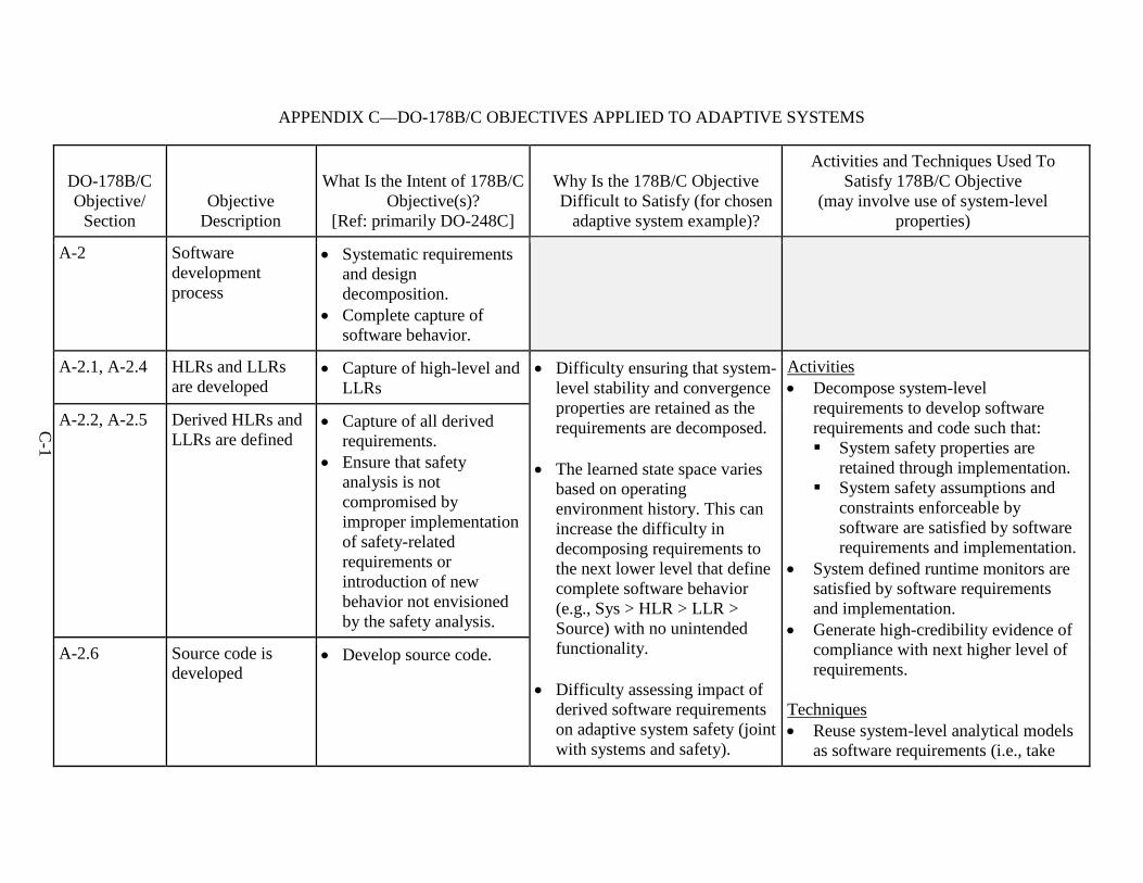
C-1
APPENDIX C—DO-178B/C OBJECTIVES APPLIED TO ADAPTIVE SYSTEMS
DO-178B/C Objective/
Section Objective
Description
What Is the Intent of 178B/C Objective(s)?
[Ref: primarily DO-248C]
Why Is the 178B/C Objective Difficult to Satisfy (for chosen
adaptive system example)?
Activities and Techniques Used To Satisfy 178B/C Objective
(may involve use of system-level properties)
A-2 Software development process
• Systematic requirementsand designdecomposition.
• Complete capture ofsoftware behavior.
A-2.1, A-2.4 HLRs and LLRs are developed
• Capture of high-level andLLRs
• Difficulty ensuring that system-level stability and convergenceproperties are retained as therequirements are decomposed.
• The learned state space variesbased on operatingenvironment history. This canincrease the difficulty indecomposing requirements tothe next lower level that definecomplete software behavior(e.g., Sys > HLR > LLR >Source) with no unintendedfunctionality.
• Difficulty assessing impact ofderived software requirementson adaptive system safety (jointwith systems and safety).
Activities • Decompose system-level
requirements to develop softwarerequirements and code such that: System safety properties are
retained through implementation. System safety assumptions and
constraints enforceable bysoftware are satisfied by softwarerequirements and implementation.
• System defined runtime monitors aresatisfied by software requirementsand implementation.
• Generate high-credibility evidence ofcompliance with next higher level ofrequirements.
Techniques • Reuse system-level analytical models
as software requirements (i.e., take
A-2.2, A-2.5 Derived HLRs and LLRs are defined
• Capture of all derivedrequirements.
• Ensure that safetyanalysis is notcompromised byimproper implementationof safety-relatedrequirements orintroduction of newbehavior not envisionedby the safety analysis.
A-2.6 Source code is developed
• Develop source code.
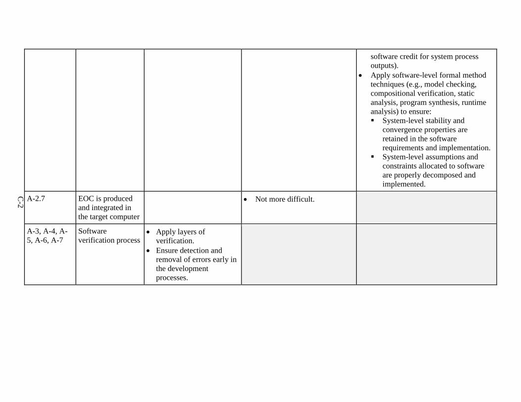
C-2
software credit for system process outputs).
• Apply software-level formal methodtechniques (e.g., model checking,compositional verification, staticanalysis, program synthesis, runtimeanalysis) to ensure: System-level stability and
convergence properties areretained in the softwarerequirements and implementation.
System-level assumptions andconstraints allocated to softwareare properly decomposed andimplemented.
A-2.7 EOC is produced and integrated in the target computer
• Not more difficult.
A-3, A-4, A-5, A-6, A-7
Software verification process
• Apply layers ofverification.
• Ensure detection andremoval of errors early inthe developmentprocesses.
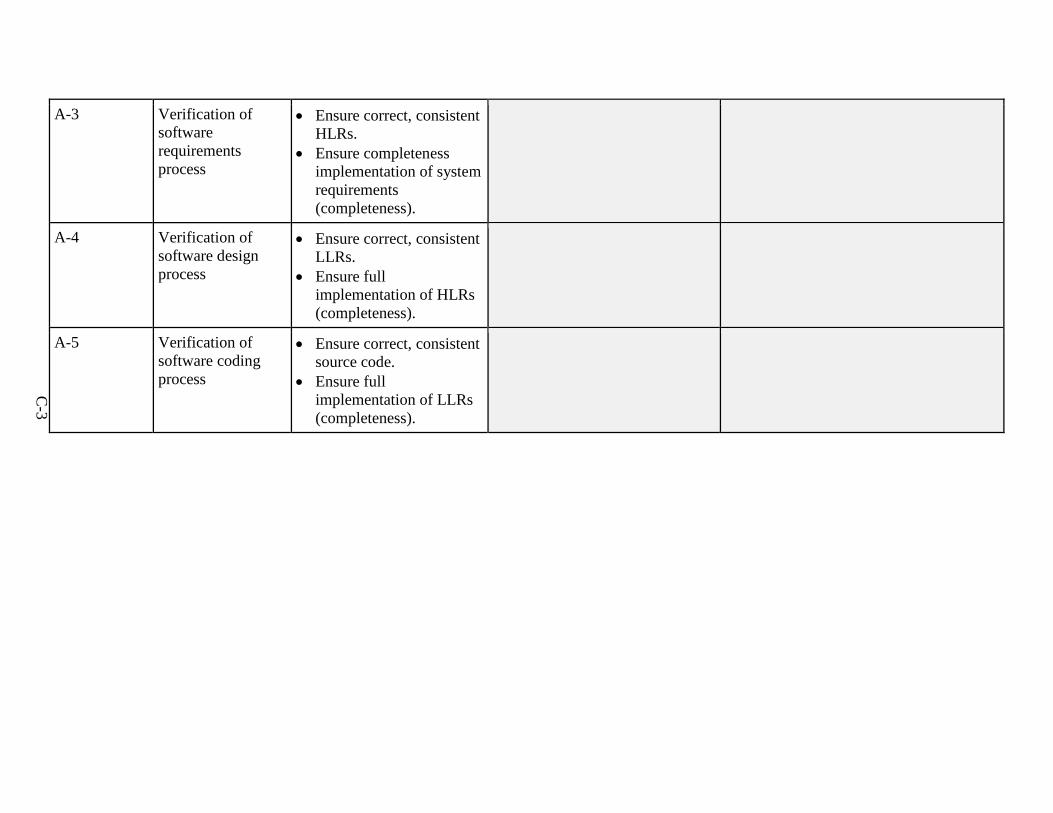
C-3
A-3 Verification of software requirements process
• Ensure correct, consistentHLRs.
• Ensure completenessimplementation of systemrequirements(completeness).
A-4 Verification of software design process
• Ensure correct, consistentLLRs.
• Ensure fullimplementation of HLRs(completeness).
A-5 Verification of software coding process
• Ensure correct, consistentsource code.
• Ensure fullimplementation of LLRs(completeness).
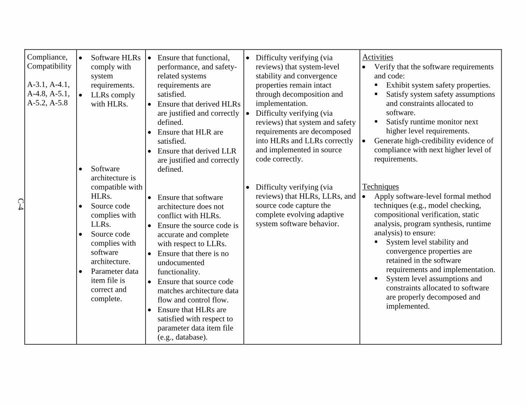
C-4
Compliance, Compatibility
A-3.1, A-4.1, A-4.8, A-5.1, A-5.2, A-5.8
• Software HLRscomply withsystemrequirements.
• LLRs complywith HLRs.
• Softwarearchitecture iscompatible withHLRs.
• Source codecomplies withLLRs.
• Source codecomplies withsoftwarearchitecture.
• Parameter dataitem file iscorrect andcomplete.
• Ensure that functional,performance, and safety-related systemsrequirements aresatisfied.
• Ensure that derived HLRsare justified and correctlydefined.
• Ensure that HLR aresatisfied.
• Ensure that derived LLRare justified and correctlydefined.
• Ensure that softwarearchitecture does notconflict with HLRs.
• Ensure the source code isaccurate and completewith respect to LLRs.
• Ensure that there is noundocumentedfunctionality.
• Ensure that source codematches architecture dataflow and control flow.
• Ensure that HLRs aresatisfied with respect toparameter data item file(e.g., database).
• Difficulty verifying (viareviews) that system-levelstability and convergenceproperties remain intactthrough decomposition andimplementation.
• Difficulty verifying (viareviews) that system and safetyrequirements are decomposedinto HLRs and LLRs correctlyand implemented in sourcecode correctly.
• Difficulty verifying (viareviews) that HLRs, LLRs, andsource code capture thecomplete evolving adaptivesystem software behavior.
Activities • Verify that the software requirements
and code: Exhibit system safety properties. Satisfy system safety assumptions
and constraints allocated tosoftware.
Satisfy runtime monitor nexthigher level requirements.
• Generate high-credibility evidence ofcompliance with next higher level ofrequirements.
Techniques • Apply software-level formal method
techniques (e.g., model checking,compositional verification, staticanalysis, program synthesis, runtimeanalysis) to ensure: System level stability and
convergence properties areretained in the softwarerequirements and implementation.
System level assumptions andconstraints allocated to softwareare properly decomposed andimplemented.
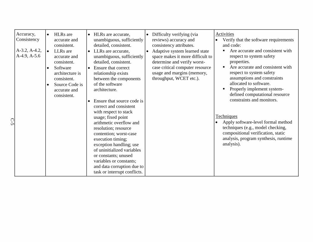
C-5
Accuracy, Consistency
A-3.2, A-4.2, A-4.9, A-5.6
• HLRs areaccurate andconsistent.
• LLRs areaccurate andconsistent.
• Softwarearchitecture isconsistent.
• Source Code isaccurate andconsistent.
• HLRs are accurate,unambiguous, sufficientlydetailed, consistent.
• LLRs are accurate,unambiguous, sufficientlydetailed, consistent.
• Ensure that correctrelationship existsbetween the componentsof the softwarearchitecture.
• Ensure that source code iscorrect and consistentwith respect to stackusage; fixed pointarithmetic overflow andresolution; resourcecontention; worst-caseexecution timing;exception handling; useof uninitialized variablesor constants; unusedvariables or constants;and data corruption due totask or interrupt conflicts.
• Difficulty verifying (viareviews) accuracy andconsistency attributes.
• Adaptive system learned statespace makes it more difficult todetermine and verify worst-case critical computer resourceusage and margins (memory,throughput, WCET etc.).
Activities • Verify that the software requirements
and code: Are accurate and consistent with
respect to system safetyproperties.
Are accurate and consistent withrespect to system safetyassumptions and constraintsallocated to software.
Properly implement system-defined computational resourceconstraints and monitors.
Techniques • Apply software-level formal method
techniques (e.g., model checking,compositional verification, staticanalysis, program synthesis, runtimeanalysis).
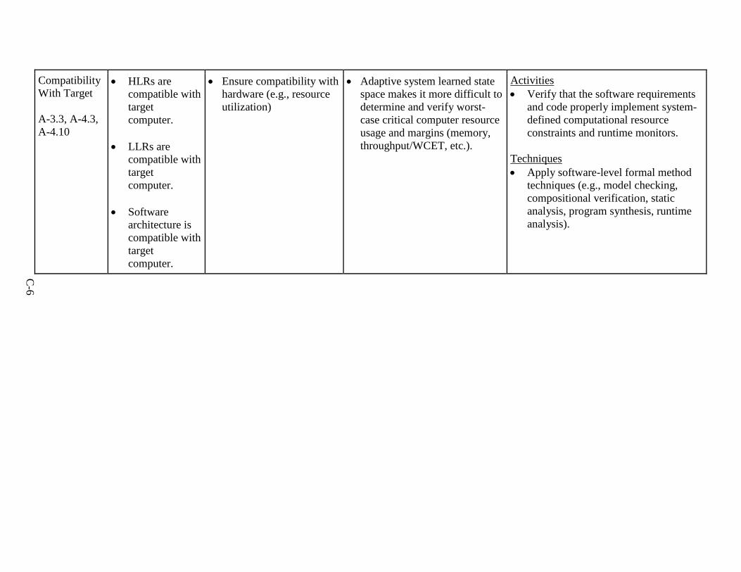
C-6
Compatibility With Target
A-3.3, A-4.3, A-4.10
• HLRs arecompatible withtargetcomputer.
• LLRs arecompatible withtargetcomputer.
• Softwarearchitecture iscompatible withtargetcomputer.
• Ensure compatibility withhardware (e.g., resourceutilization)
• Adaptive system learned statespace makes it more difficult todetermine and verify worst-case critical computer resourceusage and margins (memory,throughput/WCET, etc.).
Activities • Verify that the software requirements
and code properly implement system-defined computational resourceconstraints and runtime monitors.
Techniques • Apply software-level formal method
techniques (e.g., model checking,compositional verification, staticanalysis, program synthesis, runtimeanalysis).
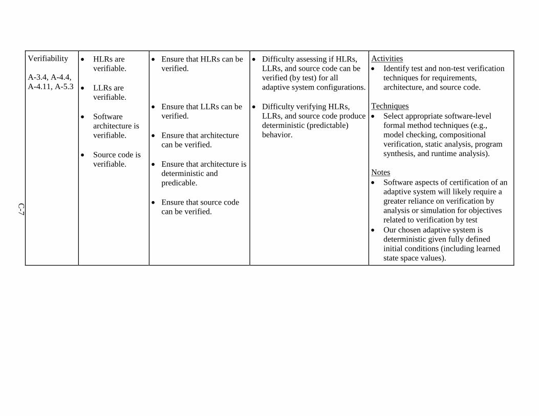
C-7
Verifiability
A-3.4, A-4.4, A-4.11, A-5.3
• HLRs areverifiable.
• LLRs areverifiable.
• Softwarearchitecture isverifiable.
• Source code isverifiable.
• Ensure that HLRs can beverified.
• Ensure that LLRs can beverified.
• Ensure that architecturecan be verified.
• Ensure that architecture isdeterministic andpredicable.
• Ensure that source codecan be verified.
• Difficulty assessing if HLRs,LLRs, and source code can beverified (by test) for alladaptive system configurations.
• Difficulty verifying HLRs,LLRs, and source code producedeterministic (predictable)behavior.
Activities • Identify test and non-test verification
techniques for requirements,architecture, and source code.
Techniques • Select appropriate software-level
formal method techniques (e.g.,model checking, compositionalverification, static analysis, programsynthesis, and runtime analysis).
Notes • Software aspects of certification of an
adaptive system will likely require agreater reliance on verification byanalysis or simulation for objectivesrelated to verification by test
• Our chosen adaptive system isdeterministic given fully definedinitial conditions (including learnedstate space values).
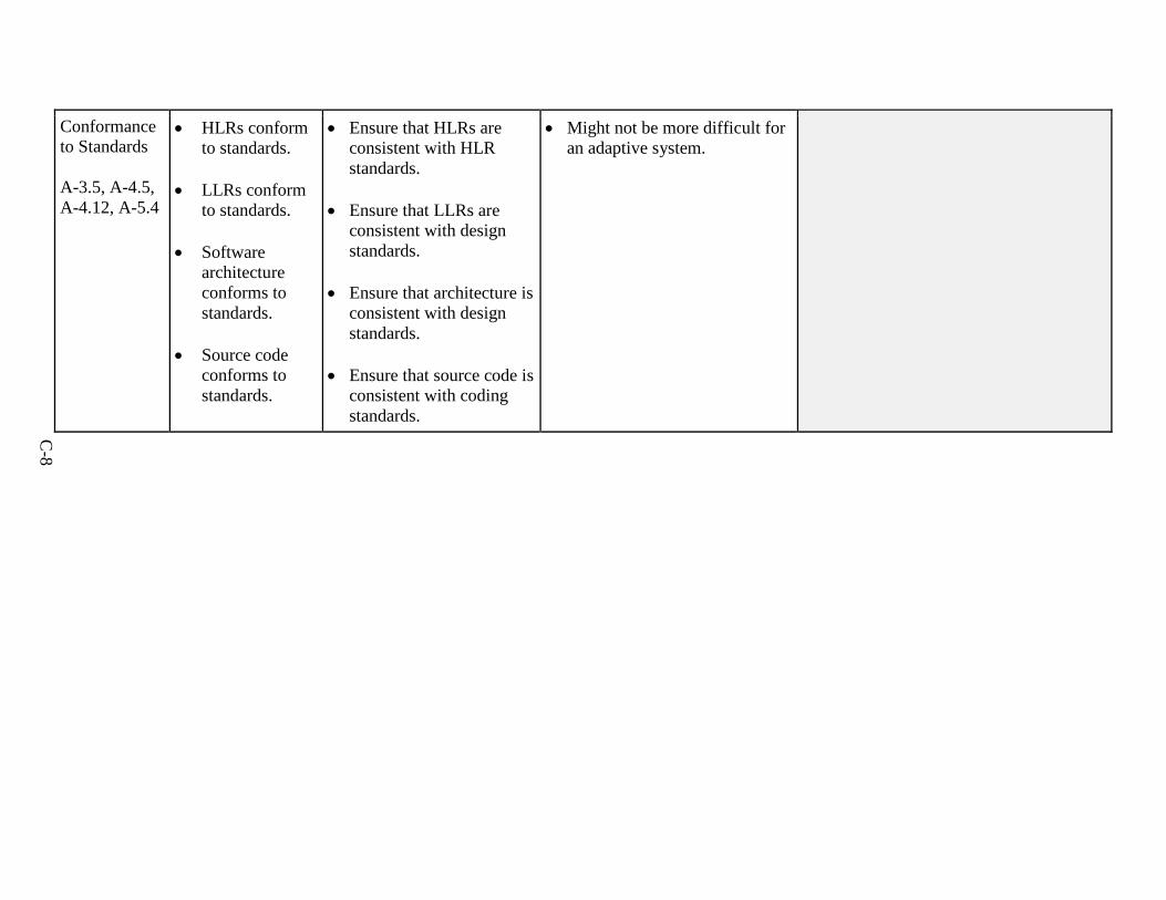
C-8
Conformance to Standards
A-3.5, A-4.5, A-4.12, A-5.4
• HLRs conformto standards.
• LLRs conformto standards.
• Softwarearchitectureconforms tostandards.
• Source codeconforms tostandards.
• Ensure that HLRs areconsistent with HLRstandards.
• Ensure that LLRs areconsistent with designstandards.
• Ensure that architecture isconsistent with designstandards.
• Ensure that source code isconsistent with codingstandards.
• Might not be more difficult foran adaptive system.
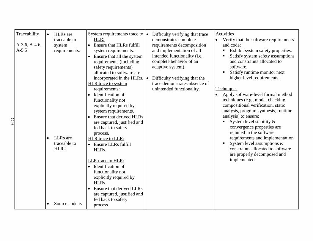
C-9
Traceability
A-3.6, A-4.6, A-5.5
• HLRs aretraceable tosystemrequirements.
• LLRs aretraceable toHLRs.
• Source code is
System requirements trace to HLR:
• Ensure that HLRs fulfillsystem requirements.
• Ensure that all the systemrequirements (includingsafety requirements)allocated to software areincorporated in the HLRs.
HLR trace to system requirements:
• Identification offunctionality notexplicitly required bysystem requirements.
• Ensure that derived HLRsare captured, justified andfed back to safetyprocess.
HLR trace to LLR: • Ensure LLRs fulfill
HLRs.
LLR trace to HLR: • Identification of
functionality notexplicitly required byHLRs.
• Ensure that derived LLRsare captured, justified andfed back to safetyprocess.
• Difficulty verifying that tracedemonstrates completerequirements decompositionand implementation of allintended functionality (i.e.,complete behavior of anadaptive system).
• Difficulty verifying that thetrace demonstrates absence ofunintended functionality.
Activities • Verify that the software requirements
and code: Exhibit system safety properties. Satisfy system safety assumptions
and constraints allocated tosoftware.
Satisfy runtime monitor nexthigher level requirements.
Techniques • Apply software-level formal method
techniques (e.g., model checking,compositional verification, staticanalysis, program synthesis, runtimeanalysis) to ensure: System level stability &
convergence properties areretained in the softwarerequirements and implementation.
System level assumptions &constraints allocated to softwareare properly decomposed andimplemented.
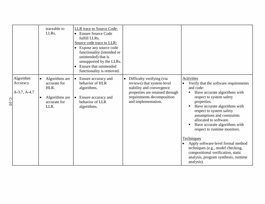
C-10
traceable to LLRs.
LLR trace to Source Code: • Ensure Source Code
fulfill LLRs.Source code trace to LLR: • Expose any source code
functionality (intended orunintended) that isunsupported by the LLRs.
• Ensure that unintendedfunctionality is removed.
Algorithm Accuracy
A-3.7, A-4.7
• Algorithms areaccurate forHLR.
• Algorithms areaccurate forLLR.
• Ensure accuracy andbehavior of HLRalgorithms.
• Ensure accuracy andbehavior of LLRalgorithms.
• Difficulty verifying (viareviews) that system-levelstability and convergenceproperties are retained throughrequirements decompositionand implementation.
Activities • Verify that the software requirements
and code: Have accurate algorithms with
respect to system safetyproperties.
Have accurate algorithms withrespect to system safetyassumptions and constraintsallocated to software.
Have accurate algorithms withrespect to runtime monitors.
Techniques • Apply software-level formal method
techniques (e.g., model checking,compositional verification, staticanalysis, program synthesis, runtimeanalysis).
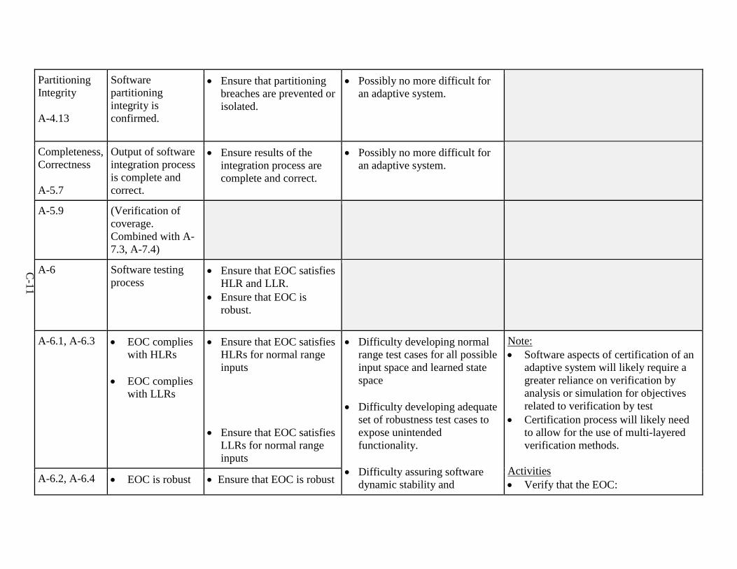
C-11
Partitioning Integrity
A-4.13
Software partitioning integrity is confirmed.
• Ensure that partitioningbreaches are prevented orisolated.
• Possibly no more difficult foran adaptive system.
Completeness, Correctness
A-5.7
Output of software integration process is complete and correct.
• Ensure results of theintegration process arecomplete and correct.
• Possibly no more difficult foran adaptive system.
A-5.9 (Verification of coverage. Combined with A-7.3, A-7.4)
A-6 Software testing process
• Ensure that EOC satisfiesHLR and LLR.
• Ensure that EOC isrobust.
A-6.1, A-6.3 • EOC complies with HLRs
• EOC complieswith LLRs
• Ensure that EOC satisfiesHLRs for normal rangeinputs
• Ensure that EOC satisfiesLLRs for normal rangeinputs
• Difficulty developing normalrange test cases for all possibleinput space and learned statespace
• Difficulty developing adequateset of robustness test cases toexpose unintendedfunctionality.
• Difficulty assuring softwaredynamic stability and
Note: • Software aspects of certification of an
adaptive system will likely require agreater reliance on verification byanalysis or simulation for objectivesrelated to verification by test
• Certification process will likely needto allow for the use of multi-layeredverification methods.
Activities • Verify that the EOC:A-6.2, A-6.4 • EOC is robust • Ensure that EOC is robust
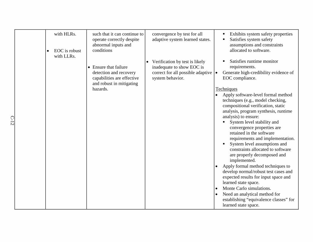
C-12
with HLRs.
• EOC is robustwith LLRs.
such that it can continue to operate correctly despite abnormal inputs and conditions
• Ensure that failuredetection and recoverycapabilities are effectiveand robust in mitigatinghazards.
convergence by test for all adaptive system learned states.
• Verification by test is likelyinadequate to show EOC iscorrect for all possible adaptivesystem behavior.
Exhibits system safety properties Satisfies system safety
assumptions and constraintsallocated to software.
Satisfies runtime monitorrequirements.
• Generate high-credibility evidence ofEOC compliance.
Techniques • Apply software-level formal method
techniques (e.g., model checking,compositional verification, staticanalysis, program synthesis, runtimeanalysis) to ensure: System level stability and
convergence properties areretained in the softwarerequirements and implementation.
System level assumptions andconstraints allocated to softwareare properly decomposed andimplemented.
• Apply formal method techniques todevelop normal/robust test cases andexpected results for input space andlearned state space.
• Monte Carlo simulations.• Need an analytical method for
establishing “equivalence classes” forlearned state space.
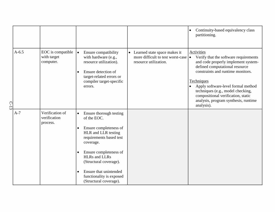
C-13
• Continuity-based equivalency classpartitioning.
A-6.5 EOC is compatible with target computer.
• Ensure compatibilitywith hardware (e.g.,resource utilization).
• Ensure detection oftarget-related errors orcompiler target-specificerrors.
• Learned state space makes itmore difficult to test worst-caseresource utilization.
Activities • Verify that the software requirements
and code properly implement system-defined computational resourceconstraints and runtime monitors.
Techniques • Apply software-level formal method
techniques (e.g., model checking,compositional verification, staticanalysis, program synthesis, runtimeanalysis).
A-7 Verification of verification process.
• Ensure thorough testingof the EOC.
• Ensure completeness ofHLR and LLR testingrequirements based testcoverage.
• Ensure completeness ofHLRs and LLRs(Structural coverage).
• Ensure that unintendedfunctionality is exposed(Structural coverage).
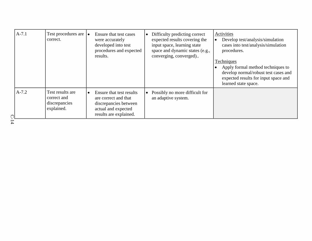
C-14
A-7.1 Test procedures are correct.
• Ensure that test caseswere accuratelydeveloped into testprocedures and expectedresults.
• Difficulty predicting correctexpected results covering theinput space, learning statespace and dynamic states (e.g.,converging, converged)..
Activities • Develop test/analysis/simulation
cases into test/analysis/simulationprocedures.
Techniques • Apply formal method techniques to
develop normal/robust test cases andexpected results for input space andlearned state space.
A-7.2 Test results are correct and discrepancies explained.
• Ensure that test resultsare correct and thatdiscrepancies betweenactual and expectedresults are explained.
• Possibly no more difficult foran adaptive system.
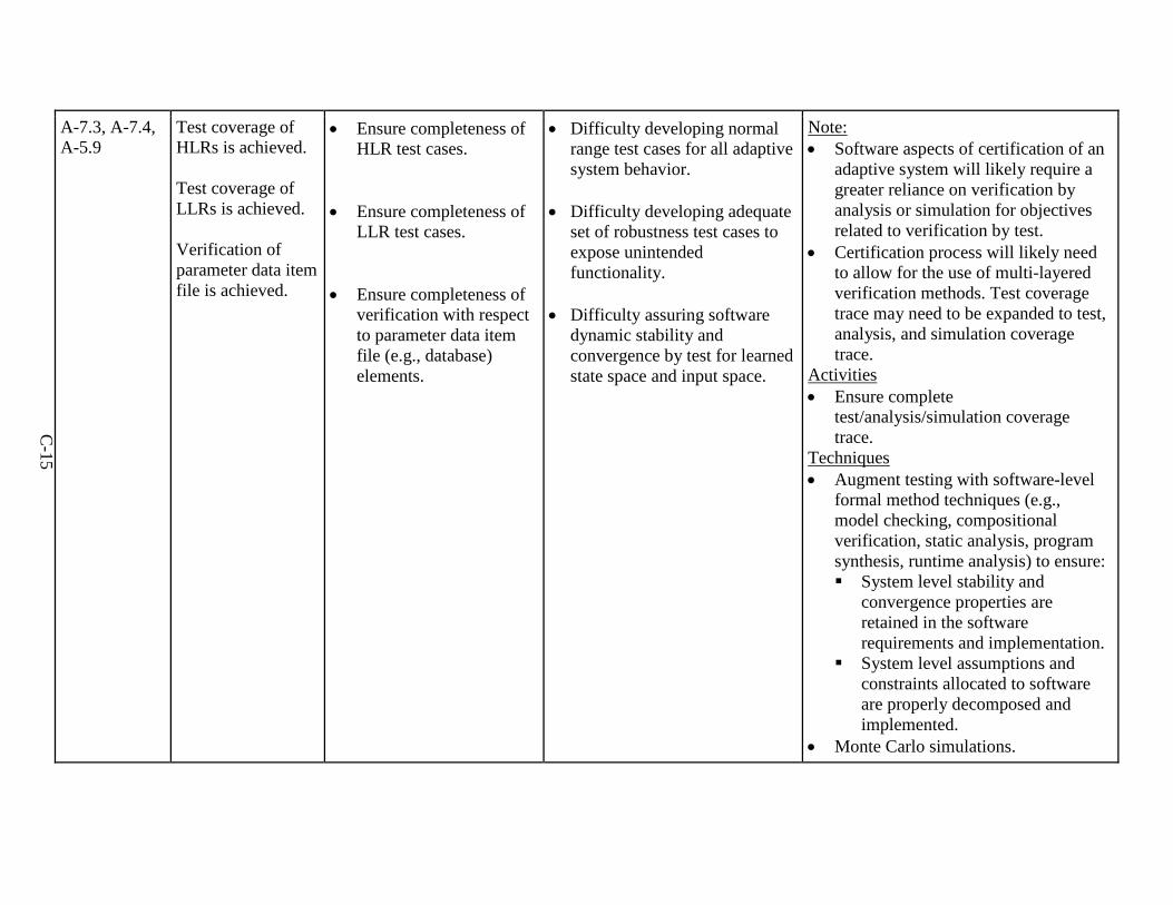
C-15
A-7.3, A-7.4, A-5.9
Test coverage of HLRs is achieved.
Test coverage of LLRs is achieved.
Verification of parameter data item file is achieved.
• Ensure completeness ofHLR test cases.
• Ensure completeness ofLLR test cases.
• Ensure completeness ofverification with respectto parameter data itemfile (e.g., database)elements.
• Difficulty developing normalrange test cases for all adaptivesystem behavior.
• Difficulty developing adequateset of robustness test cases toexpose unintendedfunctionality.
• Difficulty assuring softwaredynamic stability andconvergence by test for learnedstate space and input space.
Note: • Software aspects of certification of an
adaptive system will likely require agreater reliance on verification byanalysis or simulation for objectivesrelated to verification by test.
• Certification process will likely needto allow for the use of multi-layeredverification methods. Test coveragetrace may need to be expanded to test,analysis, and simulation coveragetrace.
Activities • Ensure complete
test/analysis/simulation coveragetrace.
Techniques • Augment testing with software-level
formal method techniques (e.g.,model checking, compositionalverification, static analysis, programsynthesis, runtime analysis) to ensure: System level stability and
convergence properties areretained in the softwarerequirements and implementation.
System level assumptions andconstraints allocated to softwareare properly decomposed andimplemented.
• Monte Carlo simulations.
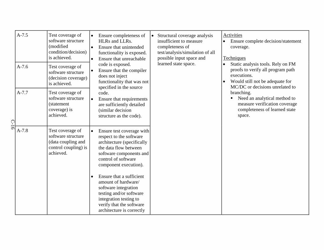
C-16
A-7.5 Test coverage of software structure (modified condition/decision) is achieved.
• Ensure completeness ofHLRs and LLRs.
• Ensure that unintendedfunctionality is exposed.
• Ensure that unreachablecode is exposed.
• Ensure that the compilerdoes not injectfunctionality that was notspecified in the sourcecode.
• Ensure that requirementsare sufficiently detailed(similar decisionstructure as the code).
• Structural coverage analysisinsufficient to measurecompleteness oftest/analysis/simulation of allpossible input space andlearned state space.
Activities • Ensure complete decision/statement
coverage.
Techniques • Static analysis tools. Rely on FM
proofs to verify all program pathexecutions.
• Would still not be adequate forMC/DC or decisions unrelated tobranching. Need an analytical method to
measure verification coveragecompleteness of learned statespace.
A-7.6 Test coverage of software structure (decision coverage) is achieved.
A-7.7 Test coverage of software structure (statement coverage) is achieved.
A-7.8 Test coverage of software structure (data coupling and control coupling) is achieved.
• Ensure test coverage withrespect to the softwarearchitecture (specificallythe data flow betweensoftware components and tcontrol of softwarecomponent execution).
• Ensure that a sufficientamount of hardware/software integrationtesting and/or softwareintegration testing toverify that the softwarearchitecture is correctly
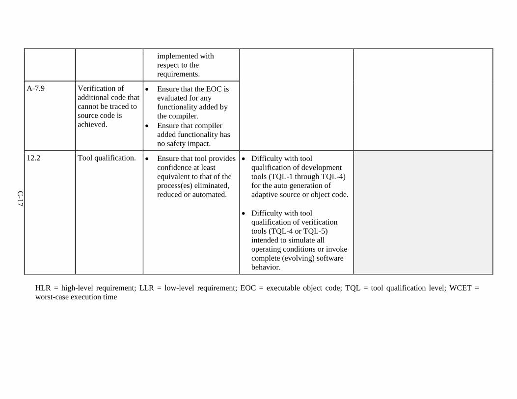
C-17
implemented with respect to the requirements.
A-7.9 Verification of additional code that cannot be traced to source code is achieved.
• Ensure that the EOC isevaluated for anyfunctionality added bythe compiler.
• Ensure that compileradded functionality hasno safety impact.
12.2 Tool qualification. • Ensure that tool provides confidence at least equivalent to that of the process(es) eliminated, reduced or automated.
• Difficulty with toolqualification of developmenttools (TQL-1 through TQL-4)for the auto generation ofadaptive source or object code.
• Difficulty with toolqualification of verificationtools (TQL-4 or TQL-5)intended to simulate alloperating conditions or invokecomplete (evolving) softwarebehavior.
HLR = high-level requirement; LLR = low-level requirement; EOC = executable object code; TQL = tool qualification level; WCET = worst-case execution time