
VERHEAD SF I SWITCHING SOLUTIONS - Electrical Power … · ing high quality electrical products ......
16
• Load break switching to 630A • Manual or automated solutions • Automatic sectionalizing • Mounting flexibility • Custom solutions since 1905 Catalog SG5-OS07 GW20-SG5-OS07 May, 2007 Supersedes SG5-OS3 O VERHEAD SF 6 INSULATED SWITCHING SOLUTIONS For applications through 38kV
-
Upload
phamnguyet -
Category
Documents
-
view
214 -
download
0
Transcript of VERHEAD SF I SWITCHING SOLUTIONS - Electrical Power … · ing high quality electrical products ......

• Load break switching to 630A• Manual or automated solutions• Automatic sectionalizing• Mounting flexibility• Custom solutions since 1905
Catalog SG5-OS07GW20-SG5-OS07May, 2007Supersedes SG5-OS3
OVERHEAD
SF6 INSULATED
SWITCHING SOLUTIONSFor applications through 38kV
4804_Overhead_Cvr.qxd 6/12/07 3:17 PM Page 1 (Cyan plate) (Magenta plate) (Yellow plate) (Black plate)

G&W Electric headquarters located in Blue Island, Illinois USA.
W O R L D W I D E E X P E R I E N C E A N D W O R L D C L A S S P E R F O R M A N C E
4804_Overhead_Cvr.qxd 6/12/07 3:17 PM Page 2 (Cyan plate) (Magenta plate) (Yellow plate) (Black plate)

Since 1905, G&W has been provid-ing high quality electrical products and innovative system solutions to utilities and electrical power users around the world. Considered a pioneer in the evolution of today’s switchgear, cable splicing and termination technology, G&W has become the fi rst in our industry to achieve both the prestigious ISO 9001:2000 and ISO 14001 certifi -cations. By combining extensive product development with state-of-the-art manufacturing, G&W contin-ues to set the standard for quality switching and fault interrupting products. Whether the applica-tion involves load switching, line sectionalizing, fault interruption or distribution automation, G&W offers a solution for overhead distribution system switching and protection.
LOAD BREAK SOLUTIONSG&W overhead load break switches are designed with all critical contact components totally protected from the environment within a sealed-for-life (per IEC standards), welded steel enclosure. Because contacts are totally sealed, they are not subject to corrosion caused by salt
or other airborne contaminants. Icing, which can hamper proper operation of exposed switching mechanisms, is also not a concern. SF6 is used because it is a safe, nontoxic, nonfl ammable, stable dielectric with excellent arc quenching properties. G&W overhead load break switches are durable and maintenance-free assuring a long ser-vice life without recurring maintenance costs.
A variety of load break switch designs are available for manual or electrically operated load switching for systems through 38kV.
Other features include: • Testing to ANSI and IEC standards. • Bushing fl exibility • Ease of automation
Compared To Air Break SwitchesG&W overhead load break switches can provide:
• An economical alternative with superior, mechanical and electrical performance.
• Totally sealed contact systems eliminating environmental corrosion and icing concerns.
• Signifi cant increase in the number of load break operations which is especially important in automation schemes where the number of switching operations typically increases.
• Minimal maintenance.
• Ease of automation.
FAULT INTERRUPTING SOLUTIONSFor applications requiring over-current protection, G&W offers a variety of automatic reclosers and sectionalizers. Solid dielectric, three phase vacuum reclosers are available through 38kV, 800A con-tinuous, 12.5kA symmetrical inter-rupting. Various bushing confi gura-tions permit application versatility. Reclosers work directly with the popular Schweitzer SEL 351R control and others. See separate catalog for detailed information.
G&W’s Solution Advantage/ General Features .................... page 3
Overhead Switching Applications ....................................... page 4
Load Break Switches with 20kA Momentary ................. pages 5-7
Load Break Switches with 40kA Momentary ............... pages 8-10
Automation Solutions ................................................... page 11-12
Switch Accessories / Options .................................... pages 13-14
Ratings and Standards ...................................................... page 15
G & W’s S O L U T I O N A D V A N T A G E
Page 3
TA B L E O F C O N T E N T S

Local ControlAdding a motor actuator and a stand-alone electronic motorcontroller can provide simple push- button operation from ground level.
Fault IsolationWhen combined with a stand-alone control and sensors, a switch can be used as a self-contained automatic sectionalizing device for automatic fault isolation. Different sectionaliz-ing controls with voltage and/or cur-rent sensors are available. Typically automatic sectionalizers utilize either time-current sensing or time-voltage sensing controls which can be used for opening line sectionalizers, or controls which require a combina-tion of voltage with current sensing. All of these logic schemes require a fault interrupting device to be upline from the sectionalizing switches. The protective device must be either locked out or programmed for a specifi c reclose interval plus a time safety factor to allow the switch to operate.
Tie SwitchesFor tie applications, the switch control senses a voltage loss on either the source or the load side to determine whether or not to close in from a normally open condition be-tween two different sources. A time component is generally required in the control logic to insure the loss of voltage on either of the sources is permanent. Once the voltage on one source has been lost for a pre-programmed period of time, the tie switch will close in restoring power to the de-energized line.
Current sensors can be added to the tie switch to tell a controller that a fault exists when the main contacts are closed. For a normally open tie, the tie may close into a fault upon loss of voltage on one feeder. The control “knows” of the faulted con-dition and would not open unless it detects a loss of voltage on the faulted feeder side signifying the up-line protective device has operated.
SWITCH APPLICATIONSSwitches play a fundamental role in improving distribution reliability. By applying switches in strategic loca-tions on the distribution system, faults can be isolated while mini-mizing the outage area, loads can be distributed according to system conditions, critical loads can be kept on line, individual protective devices or sections of line can be bypassed during routine mainte-nance, and loads can be dropped to prevent overloading the source. In short, switches are typically used to recon-fi gure a distribution system to minimize outages and increase system reliability.
MANUAL SWITCHINGBy installing manually operated switches, a user can economically redistribute power during times of planned outages for routine line maintenance, equipment replace-ment, or even seasonal load adjust-ments. Manual switches can also be used to isolate faults in areas where immediate power restoration is not necessary, or to perform an emergency sectionalizing function to quickly restore power to the cus-tomers affected by a power outage.
G&W offers a variety of switch styles depending on system ratings and automation requirements, if appli-cable. G&W switches do not require de-energizing the system prior to switching so customer service is not disrupted.
AUTOMATED SWITCHINGBy adding a motor actuator and controller to the switch operating mechanism, the user can perform all of the functions of a manually operated switch without having to dispatch a crew to the switch site. Various automation control pack-ages are available to suit many ap-plication requirements.
On a normally closed tie, the switch control would use similar logic, but no fault closing would be necessary prior to isolating the fault.
Tie switches can also be applied to automatically bypass a feeder which has locked out due to a failure, planned outage or a faulted line. If the switch closes into a fault, the tie switch would open once the upline protective device has opened, de-energizing the line.
Loop SchemesLoop schemes generally consist of two or more sources tied into a dis-tribution system to assure backup power is available if the primary feeder is lost. The scheme utilizes sectionalizing and tie switches to automatically isolate the fault and restore power to all areas unaf-fected by the fault quickly and reli-ably using the same principles and methods described previously.
Automatic TransferFor critical load applications such as hospitals, processing plants, military bases, etc., automatic transfer schemes are common. For overhead systems, this scheme requires two switches, voltage and current sensors and a voltage-time controller. Basically, a loss of volt-age on the primary source is sensed and initiates the controller to open the primary and close the alternate source switch to automatically restore power. Current sensing is used to prevent closing into a load side fault. G&W offers a variety of automatic transfer packages.
SCADA / Distribution Automation Switches can perform the above functions either autonomously or through a SCADA system where the switch controls incorporate RTUs for interfacing with a master station. A variety of SCADA applications are available which employ either a master-slave or peer-to-peer com-munications architecture.
Page 4
O V E R H E A D S W I T C H I N G A P P L I C A T I O N S

ROTARY PUFFER SWITCHES
G&W’s overhead Rotary Puffer (RP) switches are ideal for manual load break switching, standard speed (5 seconds per operation) automatic transfer or automated sectionaliz-ing on systems rated through 27kV, 630A continuous, 32kA peak and 20kA asymmetrical short circuit. The switches are tested to ap-plicable sections of ANSI and IEC standards.
FEATURESRefer to G&W’s Solution Advantage section, page 3 for general features.
Economical Package — The man-ual overhead RP switch is G&W’s most cost effective alternative to traditional gang operated air break switches.
Ease of Operation — The rotary puffer mechanism is extremely easy to operate whether from a bucket truck or ground level operator. The handle can be padlocked in the open or closed position. Downrod assem-blies are available.
Self-disengaging MotorActuator — For applications requir-ing motor control, an exclusive motor actuator assembly permits easy manual operation if control power is lost. The main shaft automatically disengages from the motor gear as-sembly after each electrical opera-tion permitting virtually effortless manual operation.
ROTARY PUFFER CONTACT PRINCIPLE
The stationary contacts and the multi-chamber rotor (an assembly of interlocking parts which form a rotational framework including mov-ing contacts) are housed in a clear cylindrical shell. The stationary contacts are supported independent of the cable entrance bushings, eliminating possible misalignment resulting from tank defl ections. Each rotating contact simultaneously disengages from two station-ary contacts per phase, providing improved interrupting capability as compared to single break contact systems.
As the rotor tube assembly turns to disengage the moving contacts, SF6 gas is compressed between the impeller and stator. The shell, phase barrier and rotor tube also act to confi ne the gas for proper compression and fl ow. The compressed SF6 gas is directed through the nozzle into the arc zone. The SF6 fl ows across the contacts cool-ing the arc over the length of the nozzle. The cooling action is in-creased by the higher pressure (due to compression) and the fl ow of gas which constantly provides a supply of cool SF6 into the arc zone.
At current zero, the temperature of the arc is reduced to the point of deionization. The SF6 gas rapidly recovers dielectric strength with-standing the system recovery voltage across the contacts. As the rotor tube assembly turns to engage the moving contacts with the stationary contacts, the impeller induces a fl ow of SF6 gas between the contacts to minimize prestrike.
StationaryContact
Nozzle
ImpellerStator
Rotor
MovingContact
Contact postion indicator
Visible Open/Close — The color coded main contact position indi-cator (green-open, red-closed) is easily visible from the ground. The indicator is connected directly to the main contact drive shaft assembly assuring accurate contact status.
Refer to Automation, Typical Specifi cations and Accessories sections for more details.
Page 5
6 3 0 A L O A D B R E A K W I T H 2 0 k A M O M E N T A R Y
RP Contact Module

Crossarm MountingKit includes two galvanized, predrilled angle channels, four stainless steel J bolts and hardware.
Approximate Dimensions 15.5kV with Pole Mounting Bracket
FRONT VIEW
25.00"635mm
Lifting ProvisionsWith (4) 1.25"
Diameter Holes
Vent
Optional 4/0Ground Lug
Ground Boss with1/2" - 13 Thread
Operator Handle withProvisions for Padlocking
in all Positions
CrossarmMounting Bracket
20.00"(508mm)
13.00"(330mm)
19.00"(483mm)
SIDE VIEWBOTTOM VIEW
Feedthru Connectors for Cable (supplied on motoroperated unit only)
V iewing Window forPressure Gauge & Contact
Position Indicator
9.00"(229mm)
52.00"(1321mm)
Optional Aerial Lugs
ROTARY PUFFER SWITCHES (CONT.)
32.00"(813mm)
8.00"(203mm)
Page 6
7.00"(178mm)
6.00"(153mm) 235
(107)
15.5
27
Voltage Approximate One-line Max Catalog Weight w/SF6
Diagram kV Number lbs. (kgs)
ORA21-376-20RP
ORA21-386-20RP
6 3 0 A L O A D B R E A K W I T H 2 0 k A M O M E N T A R Y
Typical Vertical Mounting

2) Two lifting eyes.3) Crossarm or pole mounting bracket and hardware.4) Grounding provisions.5) Gas pressure gauge and fi ll valve.6) Three line diagram and corrosion resistant nameplate.7) Spring operator.8) Manual operating handle. 9) Colored contact position indica- tor (open/green, closed/red).10) Padlock provisions for open and close positions.11) Porcelain bushings with copper conducter and hoodnut.12) Lightning arrester provisions.13) Operations counter.
MountingSwitches shall be equipped with (check one): ❏ Crossarm mounting kit ❏ Polemount bracket (horizontal) ❏ Polemount bracket (vertical)
Options The following options shall be supplied: ❏ Stainless steel tank. ❏ Low pressure warning device. ❏ Temperature compensated gas density gauge ❏ 4/0 brass ground lug. ❏ NEMA 2-hole aerial lugs. ❏ NEMA 4-hole aerial lugs. ❏ Clamp style aerial lugs. ❏ Overpressure relief device. ❏ Wildlife protectors. ❏ Lightning arresters. ❏ Potential transformers. ❏ Current transformers (600:5) (500:1) (1000:1) ❏ Down rod operator kit. Does not include rods. ❏ Motor actuator ❏ Analog voltage sensors. ❏ 600A porcelain bushings with copper rod. ❏ 600A apparatus bushing with elastomeric insulator and (AL) (CU) rod. ❏ 600A apparatus bushing with (AL) (CU) rod. ❏ Automation accessories.
TYPICAL SPECIFICATIONS
ROTARY PUFFER SWITCHES
GE NE RAL This specifi cation covers the re-quirements for manual load inter-rupting SF6 rotary puffer (RP style) switches for overhead applications.
Design Ratings and StandardsSwitches shall be designed, tested, and built per applicable sections of ANSI and IEC standards. Certi-fi ed test reports shall be provided. The manufacturer shall be ISO 9001:2000 and 14001 certifi ed. The switch assembly shall be rated:
Maximum design voltage, kV .......................15.5 ........... 27 Impulse level (BIL), kV ......................110 .......... 125One minute withstand (dry), AC kV ..................50 ............ 60 10 second withstand (wet), AC kV ..................45 .............. 5015 minute withstand, DC kV ..................53 .............. 78Continuous and load break current, Amps .................................... 630Momentary current, kA asym.................................. 20Fault-close current, kA asym (3 times) ................... 20One second current, kA sym ................................... 12Operations load interrupting endurance at 600A ............... 500Mechanical endurance, operations .......................... 2000Maximum gas leakage test, cc/second ............................ 10-7
The above ratings apply to the switch assembly and may be reduced depend-ing upon the entrances chosen. Also see Rating and Standards, page 15.
Switch Construction Switch contacts and cable entrance terminations shall be contained in a single welded, mild steel tank with entrances internally connected by tin plated copper. The protec-tion degree of the switch tank shall be IPX7 rated. Switches shall be shipped fi lled with SF6 gas at ap-prox. 9 psig (60kPa).
Switch ContactsSwitch contacts shall be of a rotary puffer design made with copper alloy contacts with silver plating to assure permanent, low contact resistance. Each rotating contact simultaneously disengages from two fi xed contacts, thus providing two break points per phase which gives improved interrupting capabil-ity as compared to switches with only a single set of break contacts. Contact travel shall be 90º to assure effi cient arc extinction and a wide open contact gap. Arcing is con-fi ned away from the main contact surfaces. The stationary contacts shall be supported independent of the cable entrance bushings, eliminating possible misalignment. Temperature rise shall not exceed ANSI C37.71 and IEC 265-1 stan-dards for this type of device.
Switch OperationEach switch shall be equipped with spring assisted operating mecha-nism capable of providing quick -make, quick-break operation. The mechanism shall be capable of delivering suffi cient torque and shall be provided with latches for each position to achieve the published load interrupting, fault closing, and momentary ratings. All switch posi-tions shall be clearly identifi ed and padlockable.
The operating mechanism shall be actuated from outside the switch tank by a permanently attached operating handle or motor actuator. The operating shaft shall be made of brass for maximum corrosion resistance. A double “O” ring type operating shaft seal shall be used for a leak resistant, long life seal. Ambient temperature range shall be -30ºC to +40ºC (-22ºF to +104ºF).
Standard Components For a manual switch the following shall be included:1) Eleven gauge mild steel tank painted light gray with stainless steel and brass fasteners.
Page 7
6 3 0 A L O A D B R E A K W I T H 2 0 k A M O M E N T A R Y
G&W’s overhead Linear Puffer (LP) load break switches are designed for operation on distribution systems rated through 38kV, 630A continuous and 40kA asymmetrical short circuit. LP switches can accommodate almost every user switching require-ment. The switches are designed and tested to applicable ANSI and IEC standards.
FEATURES Refer to G&W’s Solution Advantage section, page 3 for general features.
Heavy Duty Ratings — LP switch-es are designed for rugged duty applications. Switches are tested and rated to 40kA rms asymmetrical momentary and fault close, 1200 loadbreak operations at full rated current and 2000 mechanical opera-tions.
Visible Open/Close — A color coded contact indicator (green-open, red- closed) is standard and easily visible from ground level. An optional viewing window is available permitting visible verifi cation of con-tact position for all 3 phases.
LINEAR PUFFER SWITCHES
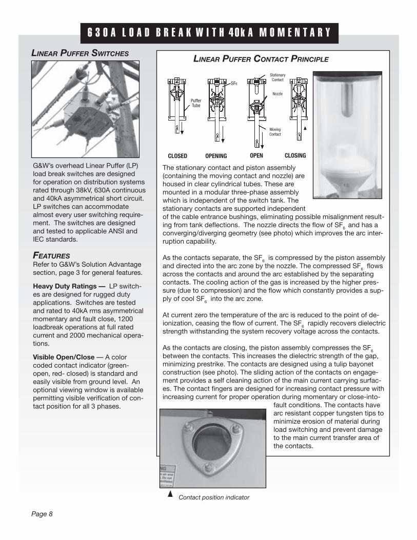
The stationary contact and piston assembly (containing the moving contact and nozzle) are housed in clear cylindrical tubes. These are mounted in a modular three-phase assembly which is independent of the switch tank. The stationary contacts are supported independent of the cable entrance bushings, eliminating possible misalignment result-ing from tank defl ections. The nozzle directs the fl ow of SF6 and has a converging/diverging geometry (see photo) which improves the arc inter-ruption capability.
As the contacts separate, the SF6 is compressed by the piston assembly and directed into the arc zone by the nozzle. The compressed SF6 fl ows across the contacts and around the arc established by the separating contacts. The cooling action of the gas is increased by the higher pres-sure (due to compression) and the fl ow which constantly provides a sup-ply of cool SF6 into the arc zone.
At current zero the temperature of the arc is reduced to the point of de-ionization, ceasing the fl ow of current. The SF6 rapidly recovers dielectric strength withstanding the system recovery voltage across the contacts.
As the contacts are closing, the piston assembly compresses the SF6 between the contacts. This increases the dielectric strength of the gap, minimizing prestrike. The contacts are designed using a tulip bayonet construction (see photo). The sliding action of the contacts on engage-ment provides a self cleaning action of the main current carrying surfac-es. The contact fi ngers are designed for increasing contact pressure with increasing current for proper operation during momentary or close-into-
fault conditions. The contacts have arc resistant copper tungsten tips to minimize erosion of material during load switching and prevent damage to the main current transfer area of the contacts.
LINEAR PUFFER CONTACT PRINCIPLE
PufferTube
StationaryContact
MovingContact
Nozzle
CLOSED OPENING OPEN CLOSING
SF6
Contact position indicator
Page 8
6 3 0 A L O A D B R E A K W I T H 4 0 k A M O M E N T A R Y

65.00"(1651mm)
31.00"(787mm)
ContactPositionIndicator
27.0
0"(6
86m
m)
Pressure Gauge, FillValve & Low Pressure
Warning Device(optional) Ground Boss With
1/2"—13 Internal Thread
OptionalMotor
OperatorOptional
AerialLugs
10"
(254
mm
)
OptionalViewing Window
Operating Shaft and LockingAssembly With Fixed
Handle
Direct PoleMount Bracket
Typical Vertical Mounting
Page 9
15.5 ORA21-376-40PI
27 ORA21-386-40PI
38 ORA21-396-40PI
285(130)
A B
Voltage Approximate One-line Max Catalog Weight w/SF6
Diagram kV Number lbs. (kgs)
6 3 0 A L O A D B R E A K W I T H 4 0 k A M O M E N T A R Y
Approximate Dimensions (15.5 kV)Typical Horizontal Mounting
7.00"(178mm)
6.00"(153mm)
8.00"(203mm)
Crossarm MountingKit includes two galvanized, predrilled angle channels, four stainless steel J bolts and hardware.

TYPICAL SPECIFICATIONS
LINEAR PUFFER SWITCHES
GE NE RAL This specifi cation covers the re-quirements for manual load inter-rupting SF6 linear puffer (LP style) switches for overhead applications.
Design Ratings and StandardsSwitches are to be designed, test-ed, and built per applicable sections of ANSI and IEC standards. Certi-fi ed test reports shall be provided. The manufacturer shall be ISO 9001:2000 and 14001 certifi ed. The switch assembly shall be rated:
Maximum design voltage, kV ................15.5 ......27 ........ 38Impulse level (BIL), kV .................110 ......125 ...... 150One minute withstand (dry), AC kV ...........50 .........60 ........ 7010 second withstand (wet) AC kV .............. 45 ....50 ......... 6015 minute withstand DC kV ..........53 ........78 ....... 103Continuous and load break current, Amps ...................................... 630Momentary current, kA asym ................................... 40Fault-close current, kA asym (3 times) ..................... 40One second current, kA sym .................................... 25Open gap withstand, kV .......................................... 20010 operating overload interrupting . capability, Amps ................... 3000Operations load interrupting endurance at 600A ............... 1200Mechanical endurance, operations ............................ 2000Maximum gas leakage test, cc/second .............................. 10-7
The above ratings apply to the switch assembly and may be reduced depend-ing upon the entrances chosen. Also see Rating and Standards, page 15.
Switch ConstructionAll switch components and entranc-es shall be assembled in a single welded, mild steel tank. Entrances
shall be internally connected by copper wire ropes and copper bus capable of handling momentary and continuous current duty. The protection degree of the switch tank shall be IPX7 rated. Switches shall be shipped fi lled with SF6 gas at approx. 9 psig (60kPa).
Switch Operation Each switch shall be equipped with an internally mounted rotary type operating mechanism capable of providing quick -make, quick-break operation. The mechanism must be capable of delivering suffi cient torque and shall be provided with latches for each position. The mechanism shall use compression type springs to assure long life and reliability. All switch positions are to be clearly identifi ed and padlock-able. The operating mechanism shall be actuated from outside the switch tank by an external operating handle. The operating shaft shall be made of stainless steel for maxi-mum corrosion resistance. A double “O” ring type operating shaft seal shall be used for a leak resistant, long life seal. Ambient temperature range shall be -30ºC to +40ºC (-22ºF to +104ºF).
Switch ContactsSwitch contacts shall be linear puffer style tulip-bayonet design and made of plated, high-conductivity copper alloy with arcing tips of copper/tung-sten alloy. The contacts shall be designed such that arcing does not occur in the area of main current interchange and contact pressure will increase with increasing current fl ow. The contact nozzle shall have a converging/diverging geometry which improves the fl ow of SF6 into the arc zone. Contact travel shall be three inches and have suffi cient open con-tact separation to assure effi cient arc extinction and to withstand fi eld DC testing levels and maintain BIL levels. The stationary contacts shall be supported independent of the cable entrance bushings. Temperature rise shall not exceed ANSI C37.71 and IEC 265-1 standards for this type of device.
Standard Components For a manual switch the following shall be included:1) Eleven gauge mild steel tank painted light gray with stainless steel and brass fasteners.2) Two lifting eyes.3) Crossarm bracket and mounting hardware.4) Grounding provisions.5) Gas pressure gauge and fi ll valve.6) Three line diagram and corrosion- resistant nameplate.7) Spring operator.8) Manual operating handle. 9) Position indicator.10) Padlock provisions for open and close positions.11) Porcelain bushings with copper conductor and hoodnut.12) Lightning arrester provisions.
MountingSwitches shall be equipped with: ❏ Crossarm mounting kit ❏ Polemount bracket (horizontal) ❏ Polemount bracket (vertical)
OptionsThe following options shall be supplied: ❏ Stainless steel tank. ❏ Low pressure warning device. ❏ SF6 density switch. ❏ Temperature compensated gas density gauge ❏ 4/0 brass ground lug. ❏ NEMA 2-hole aerial lugs. ❏ NEMA 4-hole aerial lugs. ❏ Clamp style aerial lugs. ❏ Overpressure relief device ❏ Wildlife protectors. ❏ Lightning arresters. ❏ Potential transformers. ❏ Current transformers (600:5) (500:1) (1000:1) ❏ Down rod operator kit . Does not include rods. ❏ Analog voltage sensors. ❏ 600A porcelain bushings with copper rod. ❏ 600A apparatus bushing with elastomeric insulator and (AL) (CU) rod. ❏ 600A apparatus bushing with (AL) (CU) rod.
Page 10
6 3 0 A L O A D B R E A K W I T H 4 0 k A M O M E N T A R Y

SEL-351R for sectionalizing applications.
15kV model RP switch with lightning arresters and potential transformers.
CONTROLSVarious electronic controls areavailable providing: - Local pushbutton operation and contact indication. - Remote control and monitoring interface. - NEMA 4X enclosure - Batteries and charger. An AC supply (110 or 220 V, customer supplied) is required. - Automatic lockout if SF6
pressure is below preset value. - Local / Remote Selector Switch - Provision for customer supplied RTU
Automated Sectionalizing For automated sectionalizing ap-plications, G&W overhead switches can be provided with the popu-lar Schweitzer SEL-351R control already programmed to accept customer system parameters.
Consult factory for automatic transfer solutions.
Page 11
A U T O M A T I O N S O L U T I O N S

AUTOMATIONG&W offers a full-range of automation products and services that can be customized to fi t your requirements, your budget, and your schedule.
SCADA-Ready Switches These switches are ordered with the very minimum requirements for future automation. Since our manual switches were designed with future automation in mind, most additional automation components can be easily, and economically added – when you are ready.
Motor Operated Switches These are switches ordered with motor operators and controllers for local electronic operation. All controls are ready for connection to an RTU for complete remote automation.
Fully Automated Switches These are motor operated switches and controls with an RTU, communication device, and any required voltage and current sensing. G&W will integrate and test these components as a package for your unique application.
Automation Consulting Not sure how to improve your sys-tem reliability? Not certain which switch confi guration is right for your application? Not to worry. G&W will help you select the products that best fi t your needs.
Page 12
A U T O M A T I O N S O L U T I O N S
AUTOMATION ACCESSORIES G&W can supply a number of acces-sories to further enhance the function-ality of your automated switch. Most are available for upgrades on existing manual switches – so you can add-on to and upgrade your system at your pace.
Voltage Monitoring G&W can supply voltage sensors that indicate the presence or loss of volt-age for a feeder. Alternately, we can provide potential transformers (PTs) for analog voltage measurements. These analog measurements, when coupled with analog current measurements, can provide real-time load and meter-ing values. The PTs may be connected external to the switch, or connected inside an SF6 switch tank.
Current Monitoring G&W can supply internal or external current transformers (CTs) for both overcurrent protection monitoring as well as metering analog values.
SF6 Pressure Monitoring For SF6 switches, we can provide either a low pressure warning device or, if cold temperatures are normal in your area, a density switch to indicate the unlikely event of a low dielectric condi-tion.
Faulted Circuit Indicators (FCIs) Monitoring unprotected load taps for downstream faults is a necessity for automated switches. Faulted circuit indicators can be ordered to provide in-dication of a downstream fault, thereby preventing operation into a fault.
Customer-Specifi ed Accessories G&W can integrate other monitoring, control, or data acquisition devices with our switches and automation prod-ucts. Bring us your requirements, we’ll deliver your solution.
RP style switch with motor actuator.
15kV, model RP switch with lightning arresters and potential transformers.

GAS PRESSURE GAUGE AND FILL VALVE (STANDARD)Color coded to simplify verifi cation of proper operating conditions. A Schraeder type fi ll valve permits refi lling in the fi eld. The gauge and fi ll valve are made of brass.
TEMPERATURE COMPENSATED GAS DENSITY GAUGE (OPTIONAL) - The color coded device measures internal tank gas density for maximum percision of switch operating conditions. LOW PRESSURE WARNINGDEVICE (OPTIONAL) - Permits remote indication of internal tank pressure. One N.O. and one N.C. form C contact is provided for wiring by the customer.
SF6 DENSITY SWITCH (OPTIONAL) - For LP switches only. Permits remote indication of gas density to assure proper pressure/temperature operating conditions. One N.O. and one N.C. form C contact for wiring by the customer.
GROUND LUGS (OPTIONAL)Lugs are bronze, eyebolt style for 4/0 maximum conductor cable.
VIEWING WINDOWS (OPTIONAL)For LP switches only. Windows are available for verifi cation of open contacts for all three phases.
Pressure gauge and fi ll valve
Low pressure warning device
Ground lugs
Page 13
A C C E S S O R I E S A N D O P T I O N S
Aerial Lugs — Dimensions Approximate
NEMA 2-Hole NEMA 4-Hole Clamp Style
OVERPRESSURE RELIEF DEVICE (OPTIONAL) - Overpressure relief devices permit channeled release of any vented pressure.
DOWN ROD OPERATOR (OPTIONAL) - Down rod operating mechanisms are available to permit ground level manual operation.
WILDLIFE PROTECTORS (OPTIONAL) - UV stabilized polyethylene wildlife protectors are designed to fi t over lightning arrester or insulator skirts to protect from fl ashover caused by any wildlife interference.
OPERATION COUNTERS (OPTIONAL) - Operations counters are available and viewable through a window located on the switch tank.
AERIAL LUGS (OPTIONAL)Standard lugs are tin plated copper.
Operating Handle
Ground View
Down Rod Operator
Temperature compensated gas
density gauge

For RP and LP Switches Epoxy apparatus bushing for elbow connectors de-signed to applicable ANSI/IEEE standards. Standard conductor is aluminum (CU optional). A threaded tin plated aluminum stud is standard (CU optional).
APPARATUS BUSHINGS
PORCELAIN BUSHINGS
Solid porcelain bushing with copper conductor de-signed to applicable ANSI/IEEE standards. Standard hoodnut is copper with 1.06” (27mm) dia. hood).
For RP and LP Switches
SILICONE BUSHINGSFOR RP AND LP SW ITCHE S
Welded apparatus bushing with a one piece, screw-onsilicone insulator designed to applicable ANSI/IEEEstandards. Standard conductor is aluminum for both. Insulator conductor has a .75” (19mm) dia. tin platedaluminum stud for aerial connection. Copper conductoris optional. Extra creepage silicone insulators available.
Page 14
A C C E S S O R I E S A N D O P T I O N S
15.5 11” 15” 9” 11” 11” (279) (381) (229) (279) (279)
27 15” 26” 14” 14” 14” (381) (660) (356) (356) (356)
38 20” 38” 18” -- 16” (508) (965) (457) (406)
15.5 10.4” 14” 6.2” 10” 11” (264) (356) (157) (254) (279)
27 14.4” 23.5” 10.2” 12” 12” (366) (597) (259) (305) (305)
38 17.7” 36.2” 14” -- 14” (450) (919) (356) (356)
L

Page 15
R A T I N G S A N D S T A N D A R D S
IEC STANDARDSInsulation level RP Style LP Style
- rated voltage, kV ..........................................................................12 ............24 12 ..........24 ..........36- withstand voltage, 50Hz- between phases and against earth, kV........................................28 ............50 28 ..........50 ..........70- across the isolating distance, kV..................................................32 ..............60 32 ..........60 ..........80- lightning impulse withstand voltage- between phases and against earth, kV........................................75 ............125 75..........125........150- across the isolating distance, kV..................................................85 ............145 85..........145........195
Current ratings- rated normal current, A ..............................................................630 ............630 630 ........630........630- mainly active load breaking current, A (500 CO operations) ......630 ..........630 NA..........NA ........NA- mainly active load breaking current, A (1200 CO operations) ....NA ............NA 630 ........630........630- closed loop breaking current, A ..................................................630 ............630 630 ........630........630- line-charging breaking current, A ................................................25 ............25 40 ..........40 ..........40- cable-charging breaking current, A ..............................................25 ............25 40 ..........40 ..........40- no-load transformer breaking current, A ......................................21 ............21 21 ..........21 ..........21
Short circuit ratings- short-time withstand current, Ith, kA 3s ......................................12 ..............12 16 ..........16 ..........16- peak withstand current, Idyn, kA ..................................................31.5 ......... 31.5 64 ..........64 ..........64- short-circuit making current, peak value, kA ................................31.5 ......... 31.5 64 ..........64 ..........64
ANSI STANDARDSInsulation level
- nominal voltage class, kV ............................................................15 ............25 15 ..........25........34.5- rated maximum voltage, kV ........................................................15.5 ............27 15.5 ........27 ..........38- rated continuous current, A ........................................................630 ............630 630 ........630........630- rated impulse withstand voltage, kV............................................110 ..........125 110 ........125........150
Industrial frequency withstand voltage test- 1 min. dry, kV................................................................................50 ............60 50 ..........60 ..........70- 20 s, wet, kV ................................................................................45 ..............50 45 ..........50 ..........60- DC, 25 min. withstand, kV............................................................53 ............78 53 ..........78 ........103
Breaking tests- rated continuous and load-interrupting current, A ......................630 ..........630 630 ........630........630- line charging breaking current, A ................................................25 ............25 40 ..........40 ..........40- cable charging breaking current, A ..............................................25 ..............25 40 ..........40 ..........40- no-load transformer breaking current, A ......................................21 ............21 21 ..........21 ..........21
Short-time and making current tests- short-time current, asymmetrical, rms kA. ..................................20 ..............20 40 ..........40 ..........40- short-time current, 1 s, symmetrical, kA ......................................12 ..............12 25 ..........25 ..........25
4804_Overhead_Cvr.qxd 6/12/07 3:17 PM Page 3 (Cyan plate) (Magenta plate) (Yellow plate) (Black plate)

SF6 Gas Insulated Switchgear● 15 - 35kV, 630A, up to 25kA sym.● Two and three position
● Manual or automated● Compact and dead-front
● Vacuum interrupter or fuse protection● Submersible Vault application
Solid Dielectric Switchgear● 15-35kV, 630A, up to 16kA sym.
● Epoxy encapsulated vacuum interrupters● Single phase and three phase
● Multi-way configurations● Submersible Vault application
Solid Dielectric Vacuum Reclosers● 15 - 35kV, 800A, 12.5kA sym.
● Epoxy encapsulated vacuum interrupters● Three phase and triple option
● Work with multiple controls
G&W offers a complete line of load and fault interrupting switchgear
for underground, padmount and overhead systems, including:
© May, 2007 Printed in U.S.A.
G&W ELECTRIC CO.3500 W. 127th StreetBlue Island, IL 60406(708) 388-5010FAX: (708) 388-0755Web site: www.gwelec.comISO 14001:2004 Certified
Viper Reclosers
Trident Switchgear
SF6 Insulated Switchgear
SHANGHAI G&W ELECTRIC LTD.No. 8 Qing Yun Road
Zhang Jiang Hi-Tech ParkPudong, Shanghai, China 201203
+86-21-5895-8648FAX ; +86-21-5895-6829
Web site: www.gwelec.com.cn
ISO 9001:2000 Certified Company
4804_Overhead_Cvr.qxd 6/15/07 3:25 PM Page 4 (Cyan plate) (Magenta plate) (Yellow plate) (Black plate)