

VENTILATION EquIpmENT - bvtpartners.ee · KK-18-03 4 uAB KOmFOVENT reserves the right to introduce...
120
VENTILATION EQUIPMENT
-
Upload
duongthuan -
Category
Documents
-
view
240 -
download
0
Transcript of VENTILATION EquIpmENT - bvtpartners.ee · KK-18-03 4 uAB KOmFOVENT reserves the right to introduce...
VENTILATION EquIpmENT

VENTILATION EquIpmENT
2KK-1
8-03
4212
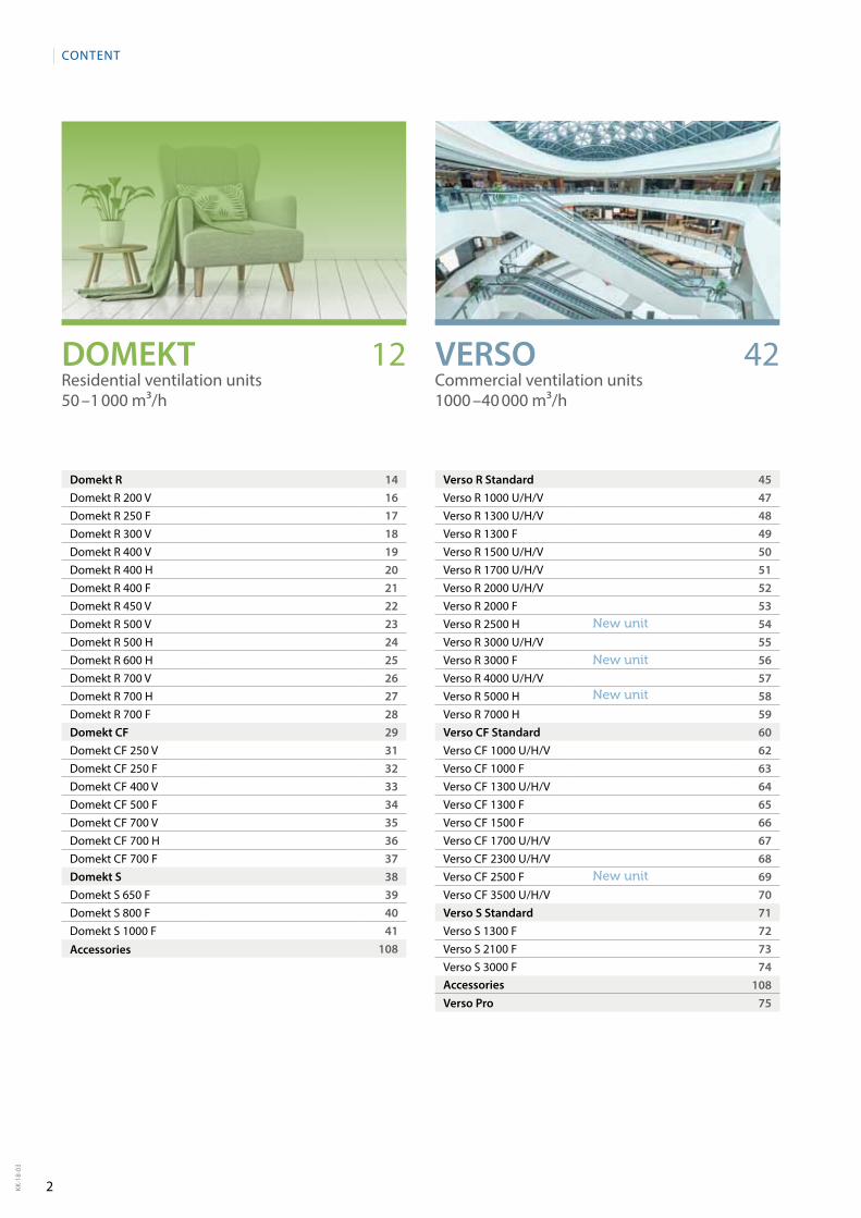
Domekt R 14Domekt R 200 V 16Domekt R 250 F 17Domekt R 300 V 18Domekt R 400 V 19Domekt R 400 H 20Domekt R 400 F 21Domekt R 450 V 22Domekt R 500 V 23Domekt R 500 H 24Domekt R 600 H 25Domekt R 700 V 26Domekt R 700 H 27Domekt R 700 F 28Domekt CF 29Domekt CF 250 V 31Domekt CF 250 F 32Domekt CF 400 V 33Domekt CF 500 F 34Domekt CF 700 V 35Domekt CF 700 H 36Domekt CF 700 F 37Domekt S 38Domekt S 650 F 39Domekt S 800 F 40Domekt S 1000 F 41
108
Verso R Standard 45Verso R 1000 u/H/V 47Verso R 1300 u/H/V 48Verso R 1300 F 49Verso R 1500 u/H/V 50Verso R 1700 u/H/V 51Verso R 2000 u/H/V 52Verso R 2000 F 53Verso R 2500 H 54Verso R 3000 u/H/V 55Verso R 3000 F 56Verso R 4000 u/H/V 57Verso R 5000 H 58Verso R 7000 H 59Verso CF Standard 60Verso CF 1000 u/H/V 62Verso CF 1000 F 63Verso CF 1300 u/H/V 64Verso CF 1300 F 65Verso CF 1500 F 66Verso CF 1700 u/H/V 67Verso CF 2300 u/H/V 68Verso CF 2500 F 69Verso CF 3500 u/H/V 70Verso S Standard 71Verso S 1300 F 72Verso S 2100 F 73Verso S 3000 F 74
108Verso Pro 75
CONTENT
VERSOCommercial ventilation units 1000 – 40 000 m³/h
DOMEKTResidential ventilation units 50 – 1 000 m³/h
Accessories
Accessories
New unit
New unit
New unit
New unit
3 KK-1
8-03
82 98
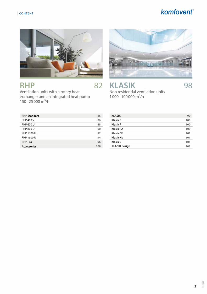
KLASIK 99Klasik R 100Klasik P 100Klasik RA 100Klasik CF 101Klasik Hg 101Klasik S 101
102
RHP Standard 85RHp 400 V 86RHp 600 u 88RHp 800 u 90RHp 1300 u 92RHp 1500 u 94RHP Pro 96
108
CONTENT
RHPVentilation units with a rotary heat exchanger and an integrated heat pump150 – 25 000 m³/h
KLASIKNon residential ventilation units 1 000 – 100 000 m³/h
KLASIK designAccessories
4KK-1
8-03
UAB KOMFOVENT reserves the right to introduce the changes of parameters and sizes in the process of improvement of the air handling units.
ADVANTAGES
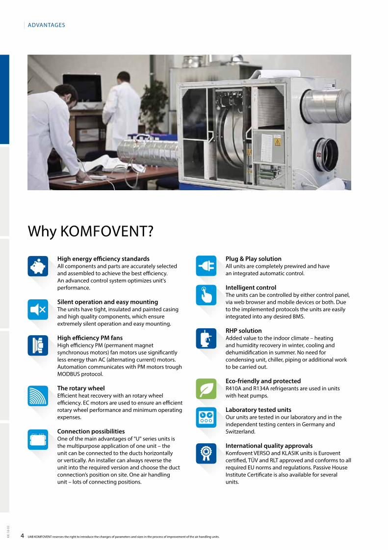
Why KOmFOVENT?
High energy efficiency standardsAll components and parts are accurately selected and assembled to achieve the best efficiency. An advanced control system optimizes unit's performance.
Silent operation and easy mountingThe units have tight, insulated and painted casing and high quality components, which ensure extremely silent operation and easy mounting.
High efficiency PM fansHigh efficiency pm (permanent magnet synchronous motors) fan motors use significantly less energy than AC (alternating current) motors. Automation communicates with pm motors trough mODBuS protocol.
The rotary wheelEfficient heat recovery with an rotary wheel efficiency. EC motors are used to ensure an efficient rotary wheel performance and minimum operating expenses.
Connection possibilitiesOne of the main advantages of "u" series units is the multipurpose application of one unit – the unit can be connected to the ducts horizontally or vertically. An installer can always reverse the unit into the required version and choose the duct connection’s position on site. One air handling unit – lots of connec ting positions.
Plug & Play solution All units are completely prewired and have an integrated automatic control.
Intelligent controlThe units can be controlled by either control panel, via web browser and mobile devices or both. Due to the implemented protocols the units are easily integrated into any desired BmS.
RHP solution Added value to the indoor climate – heating and humidity recovery in winter, cooling and dehumidification in summer. No need for condensing unit, chiller, piping or additional work to be carried out.
Eco-friendly and protectedR410A and R134A refrigerants are used in units with heat pumps.
Laboratory tested unitsOur units are tested in our laboratory and in the independent testing centers in Germany and Switzerland.
International quality approvalsKomfovent VERSO and KLASIK units is Eurovent certified, TÜV and RLT approved and conforms to all required Eu norms and regulations. passive House Institute Certificate is also available for several units.
5 KK-1
8-03
pROJECTS
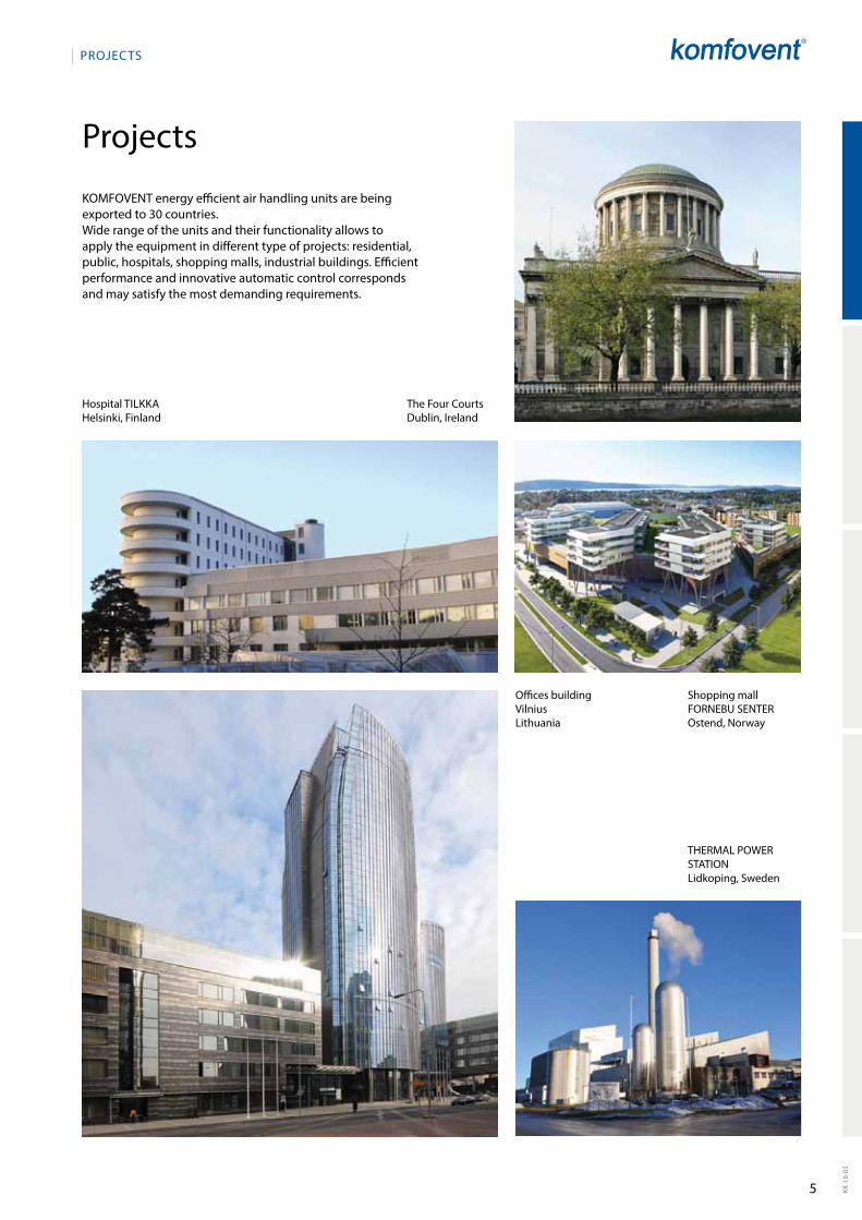
projects
KOmFOVENT energy efficient air handling units are being exported to 30 countries. Wide range of the units and their functionality allows to apply the equipment in different type of projects: residential, public, hospitals, shopping malls, industrial buildings. Efficient performance and innovative automatic control corresponds and may satisfy the most demanding requirements.
Hospital TILKKAHelsinki, Finland
Offices buildingVilnius Lithuania
The Four Courts Dublin, Ireland
Shopping mall FORNEBu SENTER Ostend, Norway
THERmAL pOWER STATIONLidkoping, Sweden
6
C 5 C 6
Automatic control system KOmFOVENT
7
INTERNET
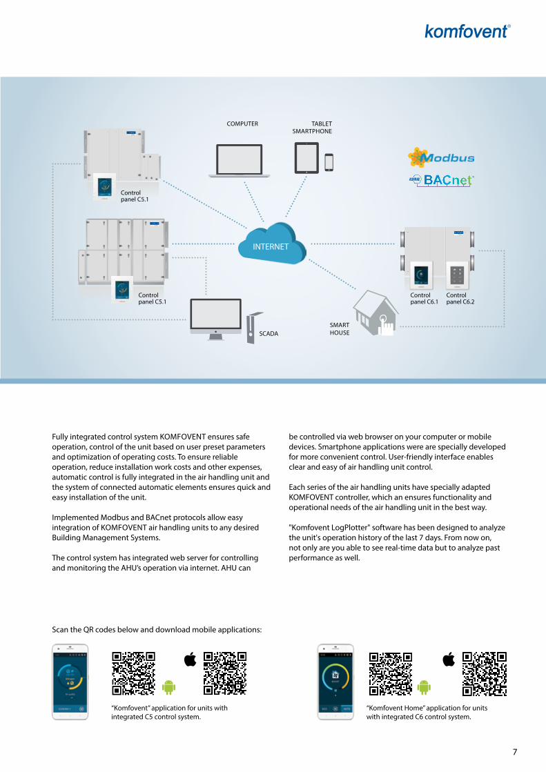
Scan the qR codes below and download mobile applications:
“Komfovent” application for units with integrated C5 control system.
“Komfovent Home” application for units with integrated C6 control system.
Fully integrated control system KOmFOVENT ensures safe operation, control of the unit based on user preset parameters and optimization of operating costs. To ensure reliable operation, reduce installation work costs and other expenses, automatic control is fully integrated in the air handling unit and the system of connected automatic elements ensures quick and easy installation of the unit.
Implemented modbus and BACnet protocols allow easy integration of KOmFOVENT air handling units to any de sired Buil ding management Systems.
The control system has integrated web server for controlling and monitoring the AHu’s operation via internet. AHu can
be controlled via web browser on your compu ter or mobile devices. Smartphone applications were are specially developed for more convenient control. user-friendly interface enables clear and easy of air handling unit control.
Each series of the air handling units have specially adapted KOmFOVENT controller, which an ensures functionality and operational needs of the air handling unit in the best way.
"Komfovent Logplotter" software has been designed to analyze the unit's operation history of the last 7 days. From now on, not only are you able to see real-time data but to analyze past performance as well.
SmART HOuSESCADA
TABLETSmARTpHONE
Control panel C6.1
Control panel C6.2
Control panel C5.1
Control panel C5.1
COmpu TER
8KK-1
8-03
UAB KOMFOVENT reserves the right to introduce the changes of parameters and sizes in the process of improvement of the air handling units.
AuTOmATIC CONTROL SySTEm
Detailed information for the user
• Airflowindication(m3/h, m3/s, l/s)• Thermalefficiencyoftheheatexchanger(%)• Heatexchangerenergyrecovery(kW)• Thermalenergysavingsindicator(%)• Airheaterenergyconsumption(kWh)• Heatexchangerrecoveredenergycounter(kWh)• Fansenergyconsumption(kWh)• SFPfactorofthefans*• Cloggingleveloffilters(%)
Various operating modes
• 5differentoperationmodes:Comfort1, Comfort2, Eco nomy1, Economy2, and Special. user may set supply and extract air vo lumes as well as air temperature for each of mode separately.
• Temperaturecontrolmodes:Supplyair/Extractair/Room/Balance. possibility to select which temperature to maintain.
• Flowcontrolmodes:ConstantAirVolume(CAV),VariableAirVolume (VAV), Directly Controlled Volume (DCV).
• Universaloperatingschedulewithupto20events,forwhichof them user can assign weekday(s) and one of five operating modes.
• Hollidayschedulingallowstheusertochangeoperatingmode or switch off the air handing unit at some dates of the year. up to 10 events are possible.
Extended control possibilities
• Controllingupto30unitsconnectedintoanetworkfromone panel.
• AbilitytoconnectthecontrollertotheInternetnetworkand manage it via a standard internet browser without any accessories.
• PossibilitytocontrolairhandlingunitbySmartphoneviaAndroid OS or iOS application software.
• Abilitytocontroltheunitnotonlybyacontrolpaneloracomputer, but also by different external devices (switch, timer, etc.) and systems (e.g. the smart house system).
Connectivity & Protocols
• ModbusRTUoverRS-485• ModbusTCPoverEthernet• BACnet/IPoverEthernet
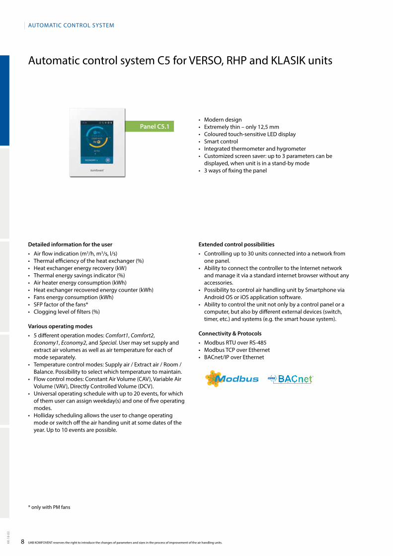
• Moderndesign• Extremelythin–only12,5mm• Colouredtouch-sensitiveLEDdisplay• Smartcontrol• Integratedthermometerandhygrometer• Customizedscreensaver:upto3parameterscanbe
displayed, when unit is in a stand-by mode• 3waysoffixingthepanel
Automatic control system C5 for VERSO, RHp and KLASIK units
Panel С5.1
*onlywithPMfans
9 KK-1
8-03
Energy saving C5 functions
Air quality control Two different air quality values may be set for two different unit operating modes (e.g. Comfort and Eco nomy). These values will be maintained by automatically increasing or reducing the intensity of ventilation
Outdoor compensated ventilation
This function adjusts the air vo lume depending on the outdoor temperature. It is possible to enter four temper-ature points where two of them define winter conditions and the other two define summer conditions. upon entering the compensation curve according to the outdoor temperature, the current intensity of ventilation is decreased or increased accordingly
Summer night cooling This function is intended for energy saving in summer: utilising the outside chill of night hours to cool down the heated rooms. The user may enable or disable function at any time as well as set the room temperature at which the function is automatically activated
Override functionOverride control of the unit can be performed by an external device (timer, switch, thermostat, etc.). The signal received from the outside activates the function which switches the unit to the pre-programmed mode igno-ring the current operating mode
minimum temperature control
This function forces the reduction of the supply and extract air volumes set by the user when the heater capacity available in the unit is insufficient and/or heat recovery does not ensure the supply of the minimum temperature to the room
Humidity controlAn air handling unit can be ordered with an air humidity control function. If this function is avai lable the user is able to choose the humidity control location: supply air, extract air or room. The user is also able to choose the method of control: humidification, dehumidification or both at a time
Circulation pumps control on demand
Both heating and cooling pumps are controlled according to the current need for heating or cooling instead of a season control
Airflowdensity compensation
Airdensitydependsonthetemperature.Thecontrollerhasafunctionwhichadjuststheairflowsautomaticallyto avoid any misba lance in rooms while being ventilated
Operation on demand The air handling unit start-up function is designed to start the unit operating in off mode when one of the selected para meters (CO2, air quality, humidity, or temperature) has exceeded the critical limit
Change-over function Control of combined water heater cooler and DX cooler reversing to the heating mode
Additional zone control Option for independently control of additional heaters and coolers in separately ventilated area. up to two additional temperature zones can be controlled
Recirculation control
The controller has a modulated extract air recirculation function. There are four control options: 1) recircula-tion according to the air quality which may be defined by one of the selected parameters: CO2, air pollution by organic components and chemical substances, humidity or temperature; 2) recirculation according to the external temperature curve; 3) recirculation according to a weekly schedule; 4) recirculation controlled by an external device
Recirculation limitation by temperature
Recirculation may be limited according to the need for heating or cooling. In cases where recirculation is controlled automatically according to one of the air quality sensors or the recirculation level set by the user, the required value of extract air recirculation may be ignored if recirculation heats or cools down the supplied air too much. In such a case recirculation is forcibly reduced until the temperature of supply air set by the user has been reached
Safety features
Rotary or plate heat exchanger failure protection
This function observes the thermal efficiency of the heat exchanger. If it does not reach the required level a fault is recorded and indicated
Rotary or plate heat exchanger anti-frost
under the low outdoor temperature conditions, this function is constantly observing decreasing tendency of the heat exchan ger thermal efficiency, determines the moment when the heat exchanger starts freezing, and activates the defrosting function automatically
Service time A warning message appears when the continuous operation of the AHu has reached 12 months
Rotor warm-up function This function forcibly activates the rotary heat exchanger if the air handling unit is turned off for some time and the temperature inside the unit or ventilation system is low enough for the rotor to freeze
Circulation pumps start-up in off mode
This function starts water circulation pumps for a short period of time when they are off longer than the set period
Warningfortoolowairflow If the air handling unit does not reach the air volume set within the time set, the user is warned by an informa-tive message
External stop Shut-down function from external device. may be used with or without an automatic unit restart
Emergency shut-down in case of fire
The external fire alarm is provided when the unit is connec ted to the building fire alarm system. There is also an internal fire alarm to detect an increased temperature inside the air handling unit or the ventilation system
Intelligent self-diagnostic Self-check function of controller and elements of the air hand ling unit. If a fault is detected, controller terminates the operation of the unit and warns about such a fault using the respective informative messages
10KK-1
8-03
82 %
4,23 kWh
2,23 kWh
0,87 kW
UAB KOMFOVENT reserves the right to introduce the changes of parameters and sizes in the process of improvement of the air handling units.
AuTOmATIC CONTROL SySTEm
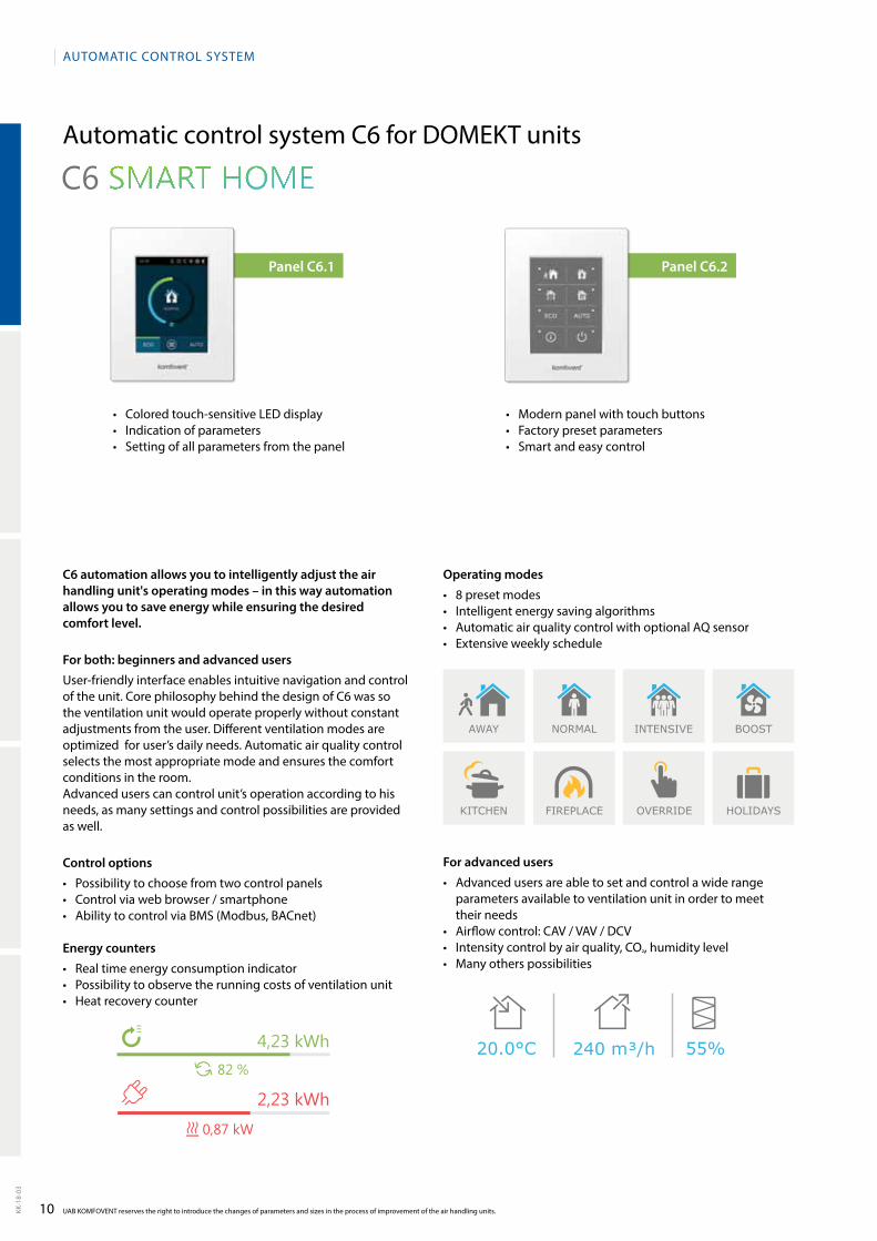
• Coloredtouch-sensitiveLEDdisplay• Indicationofparameters• Settingofallparametersfromthepanel
• Modernpanelwithtouchbuttons• Factorypresetparameters• Smartandeasycontrol
Panel С6.2Panel С6.1
Automatic control system C6 for DOmEKT units
C6 automation allows you to intelligently adjust the air handling unit's operating modes – in this way automation allows you to save energy while ensuring the desired comfort level.
For both: beginners and advanced users
user-friendly interface enables intuitive navigation and control of the unit. Core philosophy behind the design of C6 was so the ventilation unit would operate properly without constant adjustments from the user. Different ventilation modes are optimized for user’s daily needs. Automatic air quality control selects the most appropriate mode and ensures the comfort conditions in the room.Advanced users can control unit’s operation according to his needs, as many settings and control possibilities are provided as well.
Control options
• Possibilitytochoosefromtwocontrolpanels• Controlviawebbrowser/smartphone• AbilitytocontrolviaBMS(Modbus,BACnet)
Energy counters
• Realtimeenergyconsumptionindicator• Possibilitytoobservetherunningcostsofventilationunit• Heatrecoverycounter
Operating modes
• 8presetmodes• Intelligentenergysavingalgorithms• AutomaticairqualitycontrolwithoptionalAQsensor• Extensiveweeklyschedule
For advanced users
• Advancedusersareabletosetandcontrolawiderangeparameters available to ventilation unit in order to meet their needs
• Airflowcontrol:CAV/VAV/DCV• Intensitycontrolbyairquality,CO², humidity level• Manyotherspossibilities
AWAY
KITCHEN FIREPLACE HOLIDAYSOVERRIDE
NORMAL INTENSIVE BOOST

11 KK-1
8-03
* – these functions require additional accessories.
Smart control functionsSupply air temperature control The unit supply a user-defined temperature air
Extract air temperature control The unit automatically delivers air at a temperature so that the set temperature of the exhaust air is maintained
Room air temperature control The unit supports the user-set ambient room temperature, according to the temperature sensor located in the panel
Temperature balance control The temperature support value of the supply air is automatically set on the basis of the current extract air temperature, i.e. the extract air temperature and the supply air temperature will be the same
Constant air volume control (CAV) The unit supplies and extracts a constant air volume as set by the user, regardless of changes in the ventilation system
Variable air volume control (VAV) * The unit supplies and exctracts air volume correspondingly to the ventilation requirements in different premises
Directly controlled volume (DCV) The air volumes are controlled by direct external control signals
External water coil control There is estimated an additional water duct heater or cooler control that can be activated by the user on the control panel
External DX unit control There is estimated an additional external direct expansion (DX) unit control that can be activated by the user on the control panel
Weekly operation schedule It is possible to choose one of the four pre-set weekly operation schedules. If necessary, the schedule can be modified
Holidays planning The user can set the holiday dates for period when he is away. Then the unit will not operate for most of the time, but ventilate the premises occasionally
Air quality control * upon connecting the external air quality/humidity sensors, the ventilation intensity is chosen automatically. In this way, the maximum room comfort is ensured with the minimum energy cost
Operation on demand * The ventilation unit will operate when the air quality in the premises exceeds the set levels
Cool recovery During the summer season, in the conditioned premises cool from extract air is returned back into the premises
Temperature saving function The automatic function attempts to maintain comfortable temperature conditions in the premises by reducing the ventilation intensity, i.e. it prevents excessive cooling down or overheating of the premises
Free coolingWhen the room temperature air exceeds the set value, and the outdoor temperature is lower than the room temperature, the heat recovery and the other heating/cooling processes is blocked automatically and freecooling are performed only by fans
Ventilation control by external contacts
Airflowcanbecontrolledbythreeexternalcontacts,eachofwhichcanbeassignedtodifferentventilationintensity
Control via internet browser When the device is connected to the computer network or the Internet, the user-friendly web interface allows the operator to control the equipment with a computer or with another mobile device
Control with smartphones The "Komfovent Home" mobile app has the same interface as the control panel and allows the user to control the ventilation unit from any point
Safety functions
Filter clogging indication Clogging of the air filters is measured depending on the duration and intensity of the unit’s operation. The user is informed by a message, when it is time to change air filters
Water mixing system warming-up
For units with additional external water heaters/coolers, the circulation pump and mixing valve motion system is provided
Rotor warm-up and cleaning function
In order to prevent the eventual contamination of the stopped rotary heat exchanger, the unit has a periodical forced activation
Heat exchanger frost protectionUnitswithacounter-flowplateheatexchangerhaveaprimaryelectedheaterthatiscontrolledasneeded,andis operated only at the capacity to ensure frost protection. In this way, the ventilation unit can operate in low outside temperatures
Heat exchanger failure indication In units with plate or rotary heat exchanger, a control system monitors the thermal efficiency, and if it does not reach the stated level, a fault is indicated
Water heater frost protection This ensures the maximum reduction of the possibility of water freezing during the unit’s operation. When the unit is swiched off, warm water circulation is supported
Electric heater overheat protection If there is danger of overheating, heater shuts down automatically. When unit is shut down during the heating operation, fans will continue to operate for set time period
Lowairflowindication If the ventilation unit does not reach the set air volume during the specified time, the unit’s operation is stopped
Emergency shut down in case of fire
The external fire alarm is provided when the unit is connected to the building fire alarm system. There is also an internal fire alarm to detect an increased temperature inside the air handling unit or the ventilation system
Emergency shut down when temperature reaches critical limits When the supply air temperature drops below or exceeds the permitted value, the unit is stopped
Intelligent self-diagnostic Self-check function of controller and elements of the air handling unit. If a fault is detected, controller terminates the operation of the unit and warns about such a fault using the respective informative messages
DOMEKT
12
Residential ventilation units
50 – 1 000 (m3/h)
13
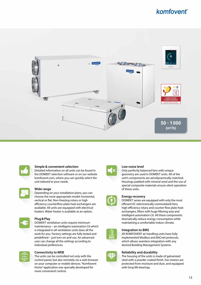
Simple & convenient selectionDetailed information on all units can be found in the DOMEKT selection software or on our website komfovent.com, where you can quickly select the unit tailored to your needs.
Wide rangeDepending on your installation plans, you can choose the most appropriate model: horizontal, vertical or flat. Non-freezing rotary or high efficiency counterflow plate heat exchangers are available. All units are equipped with electrical heaters. Water heater is available as an option.
Plug & PlayDOMEKT ventilation units require minimum maintenance – an intelligent automation C6 which is integrated in all ventilation units does all the work for you. Factory settings are fully tested and predefined – just turn on and use. An advanced user can change all the settings according to individual preferences.
Connectivity to WEBThe units can be controlled not only with the control panel, but also remotely via a web browser on your computer or mobile devices. “Komfovent Home” application was specially developed for more convenient control.
Low noise levelOnly perfectly balanced fans with unique geometry are used in DOMEKT units. All of the unit’s components are aerodynamically matched. Housings padded with mineral wool and the use of special composite materials ensure silent operation of these units.
Energy recoveryDOMEKT series are equipped with only the most efficient EC (electronically commutated) fans, high efficiency rotary and counter flow plate heat exchangers, filters with huge filtering area and intelligent automation C6. All these components dramatically reduce energy consumption while maintaining a comfortable indoor climate.
Integration to BMSAll KOMFOVENT air handling units have fully implemented Modbus and BACnet protocols, which allows seamless integration with any desired Building Management Systems.
Reliability and durabilityThe housing of the units is made of galvanized steel with a powder coated finish. Fan motors are protected from moisture and dust, and equipped with long life bearings.
14
DOMEKT
KK-1
8-03
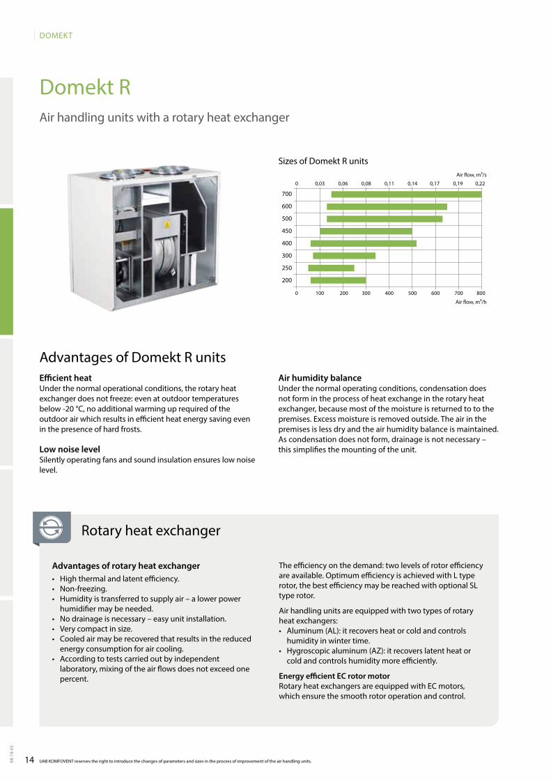
Domekt R
0 100 200 300 400 500 600 700 800
0 0,03 0,06 0,08 0,11 0,14 0,17 0,19 0,22
700
600
500
450
400
300
250
200
UAB KOMFOVENT reserves the right to introduce the changes of parameters and sizes in the process of improvement of the air handling units.
Air handling units with a rotary heat exchanger
Sizes of Domekt R units
Air flow, m³/h
Air flow, m³/s
Efficient heatUnder the normal operational conditions, the rotary heat exchanger does not freeze: even at outdoor temperatures below -20 °C, no additional warming up required of the outdoor air which results in efficient heat energy saving even in the presence of hard frosts.
Low noise levelSilently operating fans and sound insulation ensures low noise level.
Advantages of Domekt R unitsAir humidity balance Under the normal operating conditions, condensation does not form in the process of heat exchange in the rotary heat exchanger, because most of the moisture is returned to to the premises. Excess moisture is removed outside. The air in the premises is less dry and the air humidity balance is maintained. As condensation does not form, drainage is not necessary – this simplifies the mounting of the unit.
Rotary heat exchanger
Advantages of rotary heat exchanger• Highthermalandlatentefficiency.• Non-freezing.• Humidityistransferredtosupplyair–alowerpower
humidifier may be needed. • Nodrainageisnecessary–easyunitinstallation.• Verycompactinsize.• Cooledairmayberecoveredthatresultsinthereduced
energy consumption for air cooling. • Accordingtotestscarriedoutbyindependent
laboratory, mixing of the air flows does not exceed one percent.
The efficiency on the demand: two levels of rotor efficiency are available. Optimum efficiency is achieved with L type rotor, the best efficiency may be reached with optional SL type rotor.
Air handling units are equipped with two types of rotary heat exchangers:• Aluminum(AL):itrecoversheatorcoldandcontrols
humidity in winter time.• Hygroscopicaluminum(AZ):itrecoverslatentheator
cold and controls humidity more efficiently.
Energy efficient EC rotor motorRotary heat exchangers are equipped with EC motors, which ensure the smooth rotor operation and control.
15
DOMEKT
KK-1
8-03
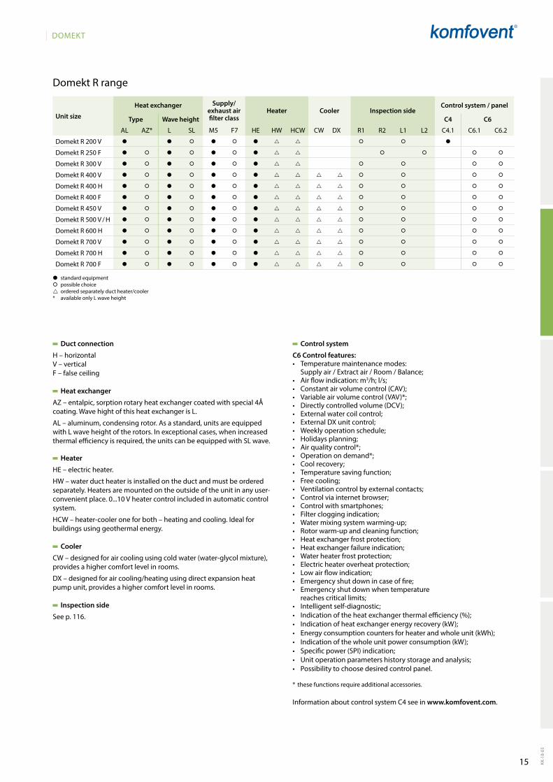
� standard equipment� possible choice ordered separately duct heater/cooler* available only L wave height
Domekt R range
Duct connection
H – horizontalV – verticalF – false ceiling
Heat exchanger
AZ–entalpic,sorptionrotaryheatexchangercoatedwithspecial4Åcoating. Wave hight of this heat exchanger is L.
AL – aluminum, condensing rotor. As a standard, units are equipped with L wave height of the rotors. In exceptional cases, when increased thermal efficiency is required, the units can be equipped with SL wave.
Heater
HE – electric heater.
HW – water duct heater is installed on the duct and must be ordered separately. Heaters are mounted on the outside of the unit in any user-convenient place. 0...10 V heater control included in automatic control system.
HCW – heater-cooler one for both – heating and cooling. Ideal for buildings using geothermal energy.
Cooler
CW – designed for air cooling using cold water (water-glycol mixture), provides a higher comfort level in rooms.
DX – designed for air cooling/heating using direct expansion heat pump unit, provides a higher comfort level in rooms.
Inspection side
See p. 116.
Control system
C6 Control features:• Temperature maintenance modes:
Supply air / Extract air / Room / Balance;• Air flow indication: m3/h; l/s;• Constant air volume control (CAV);• Variable air volume control (VAV)*;• Directly controlled volume (DCV);• External water coil control;• External DX unit control;• Weekly operation schedule;• Holidays planning;• Air quality control*;• Operation on demand*;• Cool recovery;• Temperature saving function;• Free cooling;• Ventilation control by external contacts;• Control via internet browser;• Control with smartphones;• Filter clogging indication;• Water mixing system warming-up;• Rotor warm-up and cleaning function;• Heat exchanger frost protection;• Heat exchanger failure indication;• Water heater frost protection;• Electric heater overheat protection;• Low air flow indication;• Emergency shut down in case of fire;• Emergency shut down when temperature
reaches critical limits;• Intelligent self-diagnostic;• Indication of the heat exchanger thermal efficiency (%);• Indication of heat exchanger energy recovery (kW);• Energy consumption counters for heater and whole unit (kWh);• Indication of the whole unit power consumption (kW);• Specific power (SPI) indication;• Unit operation parameters history storage and analysis;• Possibility to choose desired control panel.
* these functions require additional accessories.
Information about control system C4 see in www.komfovent.com.
Unit size
Heat exchanger Supply/exhaust air filter class
Heater Cooler Inspection sideControl system / panel
Type Wave height C4 C6
AL AZ* L SL M5 F7 HE HW HCW CW DX R1 R2 L1 L2 C4.1 C6.1 C6.2
Domekt R 200 V � � � � � � � � �
Domekt R 250 F � � � � � � � � � � �
Domekt R 300 V � � � � � � � � � � �
Domekt R 400 V � � � � � � � � � � �
Domekt R 400 H � � � � � � � � � � �
Domekt R 400 F � � � � � � � � � � �
Domekt R 450 V � � � � � � � � � � �
Domekt R 500 V / H � � � � � � � � � � �
Domekt R 600 H � � � � � � � � � � �
Domekt R 700 V � � � � � � � � � � �
Domekt R 700 H � � � � � � � � � � �
Domekt R 700 F � � � � � � � � � � �
16
DOMEKT
KK-1
8-03
A
258 m³/h43
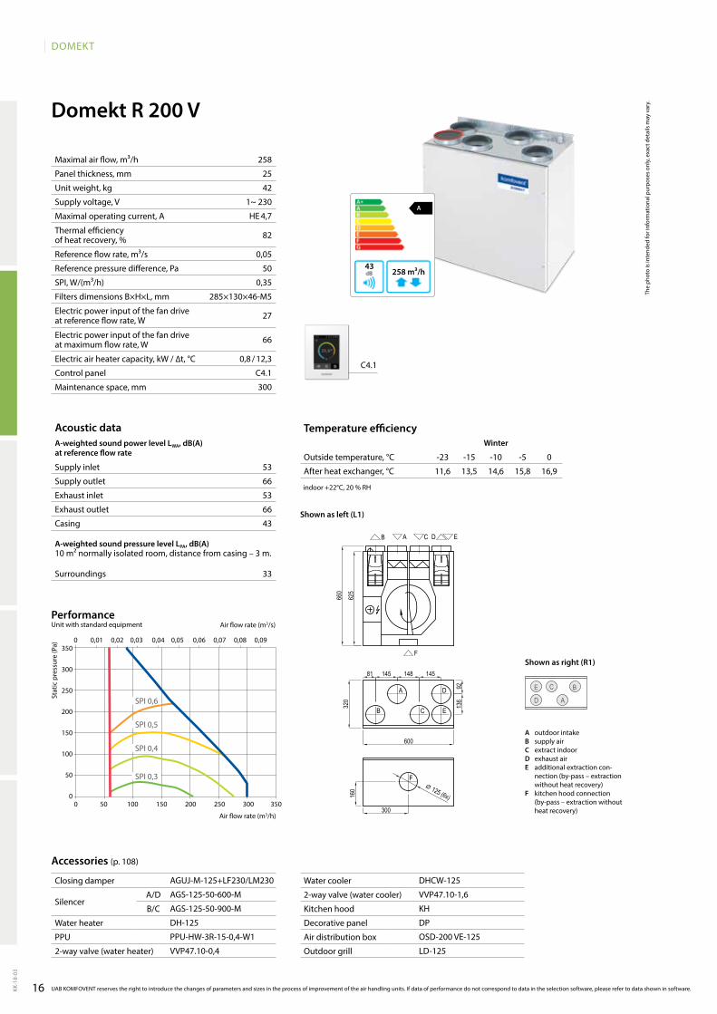
Domekt R 200 V
258
25
42
1~ 230
HE 4,7
82
0,05
50
0,35
285×130×46-M5
27
66
0,8 / 12,3
C4.1
300
D A
C E B
C4.1
11,6 13,5 14,6 15,8 16,953
66
53
66
43
33
0 0,01 0,02 0,03 0,04 0,05 0,06 0,07 0,08 0,09
0 50 100 150 200 250 300 350
350
300
250
200
150
100
50
0
SPI 0,3
SPI 0,4
SPI 0,5
SPI 0,6
AGUJ-M-125+LF230/LM230
AGS-125-50-600-M
AGS-125-50-900-M
DH-125
PPU-HW-3R-15-0,4-W1
VVP47.10-0,4
DHCW-125
VVP47.10-1,6
KH
DP
OSD-200 VE-125
LD-125
Domekt_R_200_L1
AB C D E
F
A
B C
D
E
F
160
300
81 145 148 145
136
92
320
625
660
600
⌀ 125 (6x)
Acoustic dataA-weighted sound power level LwA, dB(A)at reference flow rate
Supply inlet
Supply outlet
Exhaust inlet
Exhaust outlet
Casing
A-weighted sound pressure level LPA, dB(A) 10 m² normally isolated room, distance from casing – 3 m.
Surroundings
Maximal air flow, m³/h
Panel thickness, mm
Unit weight, kg
Supply voltage, V
Maximal operating current, A
Thermal efficiency of heat recovery, %
Reference flow rate, m³/s
Reference pressure difference, Pa
SPI, W/(m³/h)
Filters dimensions B×H×L, mm
Electric power input of the fan drive at reference flow rate, W
Electric power input of the fan drive at maximum flow rate, W
Electric air heater capacity, kW / ∆t, °C
Control panel
Maintenance space, mm
Stat
ic p
ress
ure
(Pa)
Air flow rate (m3/s)
Air flow rate (m3/h)
PerformanceUnit with standard equipment
UAB KOMFOVENT reserves the right to introduce the changes of parameters and sizes in the process of improvement of the air handling units. If data of performance do not correspond to data in the selection software, please refer to data shown in software.
Accessories (p. 108)
Temperature efficiencywinter Summer
Outside temperature, °C -23 -15 -10 -5 0 25 30 35
After heat exchanger, °C
indoor +22°C, 20 % RH
The
phot
o is
inte
nded
for i
nfor
mat
iona
l pur
pose
s on
ly, e
xact
det
ails
may
var
y.
Shown as right (R1)
Shown as left (L1)
A outdoor intakeB supply airC extract indoorD exhaust airE additional extraction con-
nection (by-pass – extraction without heat recovery)
F kitchen hood connection (by-pass – extraction without heat recovery)
Closing damper
SilencerA/D
B/C
Water heater
PPU
2-way valve (water heater)
Water cooler
2-way valve (water cooler)
Kitchen hood
Decorative panel
Air distribution box
Outdoor grill
17
DOMEKT
KK-1
8-03
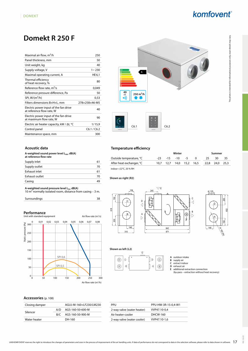
Domekt R 250 F
61
70
61
70
49
38
250
50
40
1~ 230
HE 6,1
80
0,049
50
0,53
278×258×46-M5
40
90
1/ 15,9
C6.1 / C6.2
300
A
250 m³/h49
C6.1 C6.2
D
A
C
B
D
E
C
AB
10,7 12,7 14,0 15,2 16,5 22,8 24,0 25,3
AGUJ-M-160+LF230/LM230
AGS-160-50-600-M
AGS-160-50-900-M
DH-160
PPU-HW-3R-15-0,4-W1
VVP47.10-0,4
DHCW-160
VVP47.10-1,6
0 0,01 0,02 0,03 0,04 0,05 0,06 0,07 0,08
SPI 0,5
SPI 0,6
0 50 100 150 200 250 300
300
250
200
150
100
50
0
Domekt_R_250_R2
E
C
B
D
AA
DC
B618
200
150
146
310842871
200
150
146
245106
⌀ 160 (4x)
⌀ 125
602
UAB KOMFOVENT reserves the right to introduce the changes of parameters and sizes in the process of improvement of the air handling units. If data of performance do not correspond to data in the selection software, please refer to data shown in software.
Acoustic dataA-weighted sound power level LwA, dB(A)at reference flow rate
Supply inlet
Supply outlet
Exhaust inlet
Exhaust outlet
Casing
A-weighted sound pressure level LPA, dB(A) 10 m² normally isolated room, distance from casing – 3 m.
Surroundings
Maximal air flow, m³/h
Panel thickness, mm
Unit weight, kg
Supply voltage, V
Maximal operating current, A
Thermal efficiency of heat recovery, %
Reference flow rate, m³/s
Reference pressure difference, Pa
SPI, W/(m³/h)
Filters dimensions B×H×L, mm
Electric power input of the fan drive at reference flow rate, W
Electric power input of the fan drive at maximum flow rate, W
Electric air heater capacity, kW / ∆t, °C
Control panel
Maintenance space, mm
Stat
ic p
ress
ure
(Pa)
Air flow rate (m3/s)
Air flow rate (m3/h)
PerformanceUnit with standard equipment
Accessories (p. 108)
Temperature efficiencyWinter Summer
Outside temperature, °C -23 -15 -10 -5 0 25 30 35
After heat exchanger, °C
indoor +22°C, 20 % RH
The
phot
o is
inte
nded
for i
nfor
mat
iona
l pur
pose
s on
ly, e
xact
det
ails
may
var
y.
Shown as right (R2)
Shown as left (L2)
A outdoor intakeB supply airC extract indoorD exhaust airE additional extraction connection
(by-pass – extraction without heat recovery)
Closing damper
SilencerA/D
B/C
Water heater
PPU
2-way valve (water heater)
Air heater-cooler
2-way valve (water cooler)
18
DOMEKT
KK-1
8-03
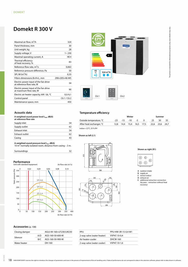
Domekt R 300 V
54
62
54
62
43
32
324
30
28
1~ 230
HE 4
83
0,063
50
0,33
290×205×46-M5
34
90
0,5/ 6,1
C6.1 / C6.2
450
C6.1 C6.2
12,8 14,4 15,4 16,5 17,5 22,6 23,6 24,7
A
324 m³/h43
D
A
CB
E
AGUJ-M-160+LF230/LM230
AGS-160-50-600-M
AGS-160-50-900-M
DH-160
PPU-HW-3R-15-0,4-W1
VVP47.10-0,4
DHCW-160
VVP47.10-1,6
0 50 100 150 200 250 300 350 400
350
300
250
200
150
100
50
0
SPI 0,3
SPI 0,4
SPI 0,5
SPI 0,6
0 0,02 0,04 0,06 0,08 0,10
Domekt_R_300_L1
C
B A
D
610
598
100
114 82
300 100
288
330
⌀ 100
⌀ 160 (4x) 502
195
Acoustic dataA-weighted sound power level LwA, dB(A)at reference flow rate
Supply inlet
Supply outlet
Exhaust inlet
Exhaust outlet
Casing
A-weighted sound pressure level LPA, dB(A) 10 m² normally isolated room, distance from casing – 3 m.
Surroundings
Maximal air flow, m³/h
Panel thickness, mm
Unit weight, kg
Supply voltage, V
Maximal operating current, A
Thermal efficiency of heat recovery, %
Reference flow rate, m³/s
Reference pressure difference, Pa
SPI, W/(m³/h)
Filters dimensions B×H×L, mm
Electric power input of the fan drive at reference flow rate, W
Electric power input of the fan drive at maximum flow rate, W
Electric air heater capacity, kW / ∆t, °C
Control panel
Maintenance space, mm
Stat
ic p
ress
ure
(Pa)
Air flow rate (m3/s)
Air flow rate (m3/h)
PerformanceUnit with standard equipment
UAB KOMFOVENT reserves the right to introduce the changes of parameters and sizes in the process of improvement of the air handling units. If data of performance do not correspond to data in the selection software, please refer to data shown in software.
Accessories (p. 108)
Temperature efficiencywinter Summer
Outside temperature, °C -23 -15 -10 -5 0 25 30 35
After heat exchanger, °C
indoor +22°C, 20 % RH
The
phot
o is
inte
nded
for i
nfor
mat
iona
l pur
pose
s on
ly, e
xact
det
ails
may
var
y.
Shown as right (R1)
Shown as left (L1)
Closing damper
SilencerA/D
B/C
Water heater
PPU
2-way valve (water heater)
Air heater-cooler
2-way valve (water cooler)
A outdoor intakeB supply airC extract indoorD exhaust airE additional extraction connection
(by-pass – extraction without heat recovery)
19
DOMEKT
KK-1
8-03
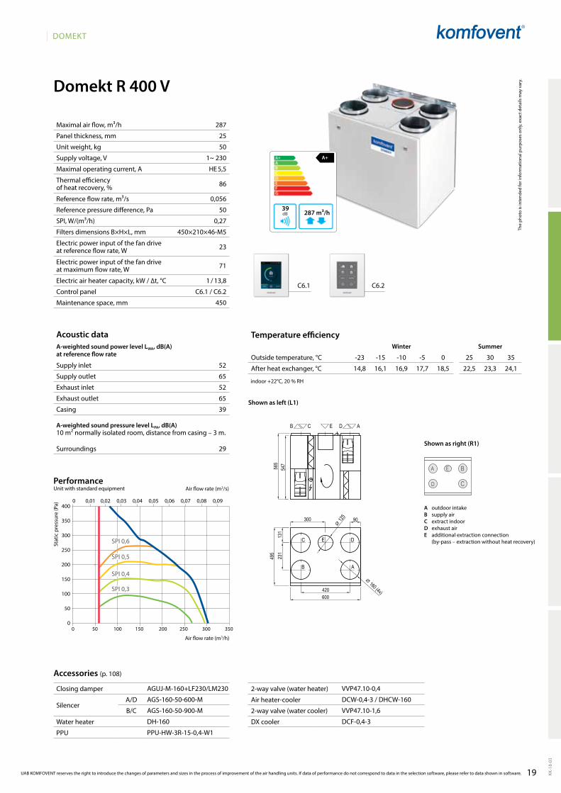
Domekt R 400 V
A+
287 m³/h39
52
65
52
65
39
29
D
A
C
BE
C6.1 C6.2
14,8 16,1 16,9 17,7 18,5 22,5 23,3 24,1
AGUJ-M-160+LF230/LM230
AGS-160-50-600-M
AGS-160-50-900-M
DH-160
PPU-HW-3R-15-0,4-W1
VVP47.10-0,4
DCW-0,4-3 / DHCW-160
VVP47.10-1,6
DCF-0,4-3
287
25
50
1~ 230
HE 5,5
86
0,056
50
0,27
450×210×46-M5
23
71
1 / 13,8
C6.1 / C6.2
450
0 50 100 150 200 250 300 350
400
350
300
250
200
150
100
50
0
0 0,01 0,02 0,03 0,04 0,05 0,06 0,07 0,08 0,09
SPI 0,6
SPI 0,3
SPI 0,4
SPI 0,5
Domekt_R_400_L1
C
B
D
A
E
B C E D A
420
90
131
600
495
231
300
565
547
⌀ 160 (4x)
⌀ 125
UAB KOMFOVENT reserves the right to introduce the changes of parameters and sizes in the process of improvement of the air handling units. If data of performance do not correspond to data in the selection software, please refer to data shown in software.
Acoustic dataA-weighted sound power level LwA, dB(A)at reference flow rate
Supply inlet
Supply outlet
Exhaust inlet
Exhaust outlet
Casing
A-weighted sound pressure level LPA, dB(A) 10 m² normally isolated room, distance from casing – 3 m.
Surroundings
Maximal air flow, m³/h
Panel thickness, mm
Unit weight, kg
Supply voltage, V
Maximal operating current, A
Thermal efficiency of heat recovery, %
Reference flow rate, m³/s
Reference pressure difference, Pa
SPI, W/(m³/h)
Filters dimensions B×H×L, mm
Electric power input of the fan drive at reference flow rate, W
Electric power input of the fan drive at maximum flow rate, W
Electric air heater capacity, kW / ∆t, °C
Control panel
Maintenance space, mm
Stat
ic p
ress
ure
(Pa)
Air flow rate (m3/s)
Air flow rate (m3/h)
PerformanceUnit with standard equipment
Accessories (p. 108)
Temperature efficiencyWinter Summer
Outside temperature, °C -23 -15 -10 -5 0 25 30 35
After heat exchanger, °C
indoor +22°C, 20 % RH
The
phot
o is
inte
nded
for i
nfor
mat
iona
l pur
pose
s on
ly, e
xact
det
ails
may
var
y.
Shown as right (R1)
Shown as left (L1)
A outdoor intakeB supply airC extract indoorD exhaust airE additional extraction connection
(by-pass – extraction without heat recovery)
Closing damper
SilencerA/D
B/C
Water heater
PPU
2-way valve (water heater)
Air heater-cooler
2-way valve (water cooler)
DX cooler
20
DOMEKT
KK-1
8-03
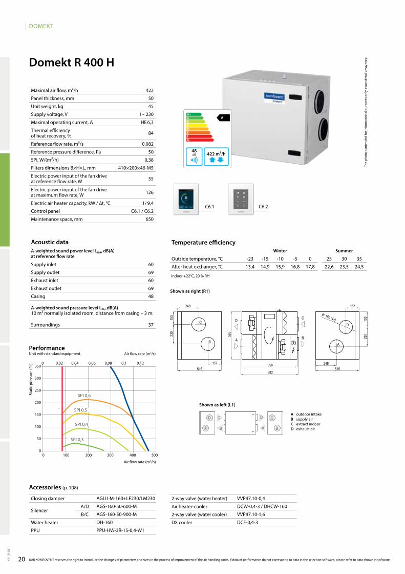
Domekt R 400 H
A
422 m³/h48
422
50
45
1~ 230
HE 6,3
84
0,082
50
0,38
410×200×46-M5
55
126
1/ 9,4
C6.1 / C6.2
650
60
69
60
69
48
37
13,4 14,9 15,9 16,8 17,8 22,6 23,5 24,5
C6.1 C6.2
AGUJ-M-160+LF230/LM230
AGS-160-50-600-M
AGS-160-50-900-M
DH-160
PPU-HW-3R-15-0,4-W1
VVP47.10-0,4
DCW-0,4-3 / DHCW-160
VVP47.10-1,6
DCF-0,4-3
0 100 200 300 400 500
350
300
250
200
150
100
50
0
SPI 0,3
SPI 0,4
SPI 0,5
SPI 0,6
0 0,02 0,04 0,06 0,08 0,1 0,12
Domekt_R_400_R1
C
B
D
A
C
B
D
A
682
650
565
230
183
248515
157
230
153
157515
248
⌀ 160 (4x)
D
A
C
B
DC
AB
Acoustic dataA-weighted sound power level LwA, dB(A)at reference flow rate
Supply inlet
Supply outlet
Exhaust inlet
Exhaust outlet
Casing
A-weighted sound pressure level LPA, dB(A) 10 m² normally isolated room, distance from casing – 3 m.
Surroundings
Maximal air flow, m³/h
Panel thickness, mm
Unit weight, kg
Supply voltage, V
Maximal operating current, A
Thermal efficiency of heat recovery, %
Reference flow rate, m³/s
Reference pressure difference, Pa
SPI, W/(m³/h)
Filters dimensions B×H×L, mm
Electric power input of the fan drive at reference flow rate, W
Electric power input of the fan drive at maximum flow rate, W
Electric air heater capacity, kW / ∆t, °C
Control panel
Maintenance space, mm
Stat
ic p
ress
ure
(Pa)
Air flow rate (m3/s)
Air flow rate (m3/h)
PerformanceUnit with standard equipment
UAB KOMFOVENT reserves the right to introduce the changes of parameters and sizes in the process of improvement of the air handling units. If data of performance do not correspond to data in the selection software, please refer to data shown in software.
Accessories (p. 108)
Temperature efficiencywinter Summer
Outside temperature, °C -23 -15 -10 -5 0 25 30 35
After heat exchanger, °C
indoor +22°C, 20 % RH
The
phot
o is
inte
nded
for i
nfor
mat
iona
l pur
pose
s on
ly, e
xact
det
ails
may
var
y.
Shown as right (R1)
Shown as left (L1)
A outdoor intakeB supply airC extract indoorD exhaust air
Closing damper
SilencerA/D
B/C
Water heater
PPU
2-way valve (water heater)
Air heater-cooler
2-way valve (water cooler)
DX cooler
21
DOMEKT
KK-1
8-03
0 0,02 0,04 0,06 0,08 0,1 0,12 0,14 0,16
0 100 200 300 400 500 600
300
250
200
150
100
50
0
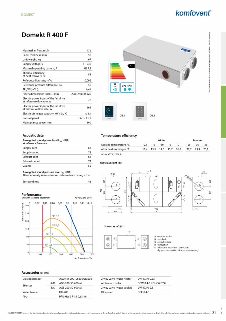
Domekt R 400 F
472
50
67
1~ 230
HE 7,3
81
0,092
50
0,44
278×258×46-M5
72
165
1 / 8,4
C6.1 / C6.2
300
63
72
63
72
52
41
A
472 m³/h52
C6.1 C6.2
AGUJ-M-200+LF230/LM230
AGS-200-50-600-M
AGS-200-50-900-M
DH-200
PPU-HW-3R-15-0,63-W1
VVP47.10-0,63
DCW-0,4-3 / DHCW-200
VVP47.10-2,5
DCF-0,4-3
11,4 13,3 14,5 15,7 16,8 22,7 23,9 25,1
SPI 0,6
SPI 0,3
SPI 0,4
SPI 0,5
D
A
B
C
D
C A
B
E
Domekt_R_400_R1
B
C
D
A
E
A
D B
C
12021170
310
330
225
700
310
225
145
387 130
720
⌀ 200 (4x)
⌀ 125
145
UAB KOMFOVENT reserves the right to introduce the changes of parameters and sizes in the process of improvement of the air handling units. If data of performance do not correspond to data in the selection software, please refer to data shown in software.
Acoustic dataA-weighted sound power level LwA, dB(A)at reference flow rate
Supply inlet
Supply outlet
Exhaust inlet
Exhaust outlet
Casing
A-weighted sound pressure level LPA, dB(A) 10 m² normally isolated room, distance from casing – 3 m.
Surroundings
Maximal air flow, m³/h
Panel thickness, mm
Unit weight, kg
Supply voltage, V
Maximal operating current, A
Thermal efficiency of heat recovery, %
Reference flow rate, m³/s
Reference pressure difference, Pa
SPI, W/(m³/h)
Filters dimensions B×H×L, mm
Electric power input of the fan drive at reference flow rate, W
Electric power input of the fan drive at maximum flow rate, W
Electric air heater capacity, kW / ∆t, °C
Control panel
Maintenance space, mm
Stat
ic p
ress
ure
(Pa)
Air flow rate (m3/s)
Air flow rate (m3/h)
PerformanceUnit with standard equipment
Accessories (p. 108)
Temperature efficiencyWinter Summer
Outside temperature, °C -23 -15 -10 -5 0 25 30 35
After heat exchanger, °C
indoor +22°C, 20 % RH
The
phot
o is
inte
nded
for i
nfor
mat
iona
l pur
pose
s on
ly, e
xact
det
ails
may
var
y.
Shown as right (R1)
Shown as left (L1)
A outdoor intakeB supply airC extract indoorD exhaust airE additional extraction connection
(by-pass – extraction without heat recovery)
Closing damper
SilencerA/D
B/C
Water heater
PPU
2-way valve (water heater)
Air heater-cooler
2-way valve (water cooler)
DX cooler
22
DOMEKT
KK-1
8-03
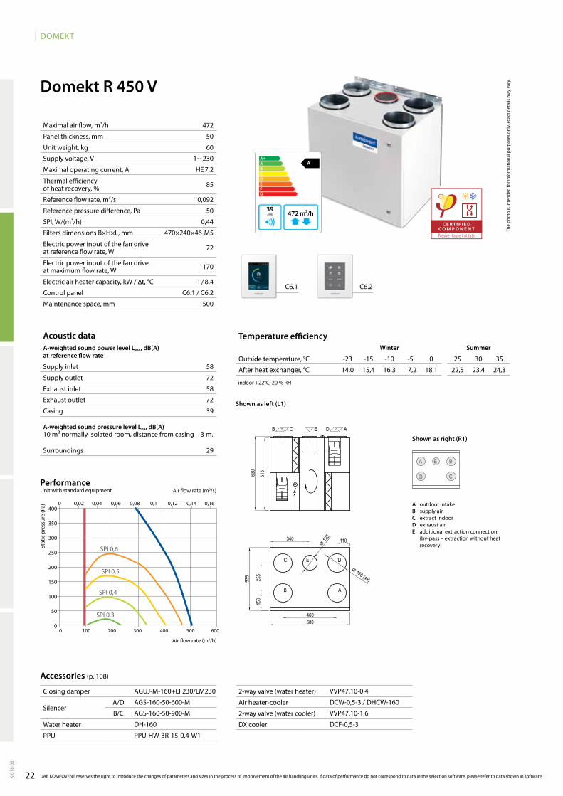
Domekt R 450 V
A
472 m³/h39
472
50
60
1~ 230
HE 7,2
85
0,092
50
0,44
470×240×46-M5
72
170
1 / 8,4
C6.1 / C6.2
500
58
72
58
72
39
29
C6.1 C6.2
14,0 15,4 16,3 17,2 18,1 22,5 23,4 24,3
AGUJ-M-160+LF230/LM230
AGS-160-50-600-M
AGS-160-50-900-M
DH-160
PPU-HW-3R-15-0,4-W1
VVP47.10-0,4
DCW-0,5-3 / DHCW-160
VVP47.10-1,6
DCF-0,5-3
D
A
C
BE
0 0,02 0,04 0,06 0,08 0,1 0,12 0,14 0,16
0 100 200 300 400 500 600
400
350
300
250
200
150
100
50
0
SPI 0,3
SPI 0,4
SPI 0,5
SPI 0,6
Domekt_R_450_L1
C
B A
DE
EB C D A
460
340
680
110
535
615
630
150
255
⌀ 125
⌀ 160 (4x)
Acoustic dataA-weighted sound power level LwA, dB(A)at reference flow rate
Supply inlet
Supply outlet
Exhaust inlet
Exhaust outlet
Casing
A-weighted sound pressure level LPA, dB(A) 10 m² normally isolated room, distance from casing – 3 m.
Surroundings
Maximal air flow, m³/h
Panel thickness, mm
Unit weight, kg
Supply voltage, V
Maximal operating current, A
Thermal efficiency of heat recovery, %
Reference flow rate, m³/s
Reference pressure difference, Pa
SPI, W/(m³/h)
Filters dimensions B×H×L, mm
Electric power input of the fan drive at reference flow rate, W
Electric power input of the fan drive at maximum flow rate, W
Electric air heater capacity, kW / ∆t, °C
Control panel
Maintenance space, mm
Stat
ic p
ress
ure
(Pa)
Air flow rate (m3/s)
Air flow rate (m3/h)
PerformanceUnit with standard equipment
UAB KOMFOVENT reserves the right to introduce the changes of parameters and sizes in the process of improvement of the air handling units. If data of performance do not correspond to data in the selection software, please refer to data shown in software.
Accessories (p. 108)
Temperature efficiencywinter Summer
Outside temperature, °C -23 -15 -10 -5 0 25 30 35
After heat exchanger, °C
indoor +22°C, 20 % RH
The
phot
o is
inte
nded
for i
nfor
mat
iona
l pur
pose
s on
ly, e
xact
det
ails
may
var
y.
Shown as right (R1)
Shown as left (L1)
A outdoor intakeB supply airC extract indoorD exhaust airE additional extraction connection
(by-pass – extraction without heat recovery)
Closing damper
SilencerA/D
B/C
Water heater
PPU
2-way valve (water heater)
Air heater-cooler
2-way valve (water cooler)
DX cooler
23
DOMEKT
KK-1
8-03
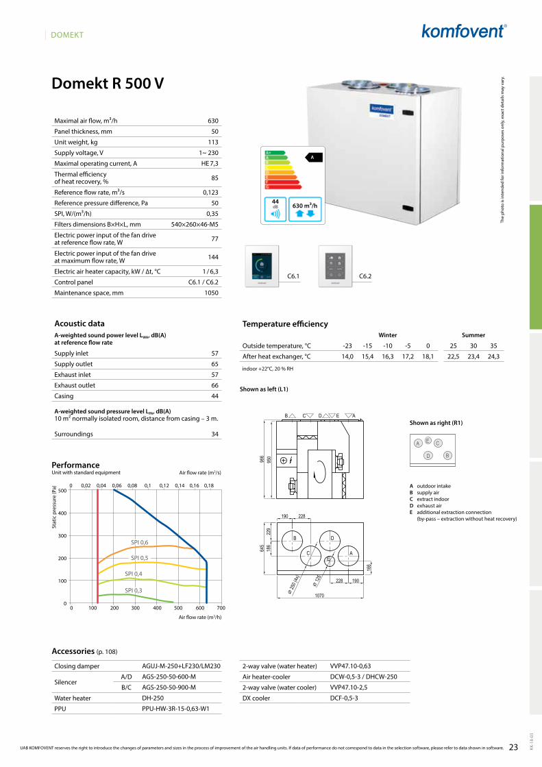
Domekt R 500 V
A
630 m³/h44
630
50
113
1~ 230
HE 7,3
85
0,123
50
0,35
540×260×46-M5
77
144
1 / 6,3
C6.1 / C6.2
1050
57
65
57
66
44
34
C6.1 C6.2
14,0 15,4 16,3 17,2 18,1 22,5 23,4 24,3
AGUJ-M-250+LF230/LM230
AGS-250-50-600-M
AGS-250-50-900-M
DH-250
PPU-HW-3R-15-0,63-W1
VVP47.10-0,63
DCW-0,5-3 / DHCW-250
VVP47.10-2,5
DCF-0,5-3
D
A
B
CE
500
400
300
200
100
0
0 0,02 0,04 0,06 0,08 0,1 0,12 0,14 0,16 0,18
0 100 200 300 400 500 600 700
SPI 0,3
SPI 0,4
SPI 0,5
SPI 0,6
Domekt_R_500_L1
AE
C
B D
B C ED A
966
950
645
1070
190228
229
186
166
⌀ 12
5
190 228
⌀ 25
0 (4x
)
UAB KOMFOVENT reserves the right to introduce the changes of parameters and sizes in the process of improvement of the air handling units. If data of performance do not correspond to data in the selection software, please refer to data shown in software.
Acoustic dataA-weighted sound power level LwA, dB(A)at reference flow rate
Supply inlet
Supply outlet
Exhaust inlet
Exhaust outlet
Casing
A-weighted sound pressure level LPA, dB(A) 10 m² normally isolated room, distance from casing – 3 m.
Surroundings
Maximal air flow, m³/h
Panel thickness, mm
Unit weight, kg
Supply voltage, V
Maximal operating current, A
Thermal efficiency of heat recovery, %
Reference flow rate, m³/s
Reference pressure difference, Pa
SPI, W/(m³/h)
Filters dimensions B×H×L, mm
Electric power input of the fan drive at reference flow rate, W
Electric power input of the fan drive at maximum flow rate, W
Electric air heater capacity, kW / ∆t, °C
Control panel
Maintenance space, mm
Stat
ic p
ress
ure
(Pa)
Air flow rate (m3/s)
Air flow rate (m3/h)
PerformanceUnit with standard equipment
Accessories (p. 108)
Temperature efficiencyWinter Summer
Outside temperature, °C -23 -15 -10 -5 0 25 30 35
After heat exchanger, °C
indoor +22°C, 20 % RH
The
phot
o is
inte
nded
for i
nfor
mat
iona
l pur
pose
s on
ly, e
xact
det
ails
may
var
y.
Shown as left (L1)
Shown as right (R1)
A outdoor intakeB supply airC extract indoorD exhaust airE additional extraction connection
(by-pass – extraction without heat recovery)
Closing damper
SilencerA/D
B/C
Water heater
PPU
2-way valve (water heater)
Air heater-cooler
2-way valve (water cooler)
DX cooler
24
DOMEKT
KK-1
8-03
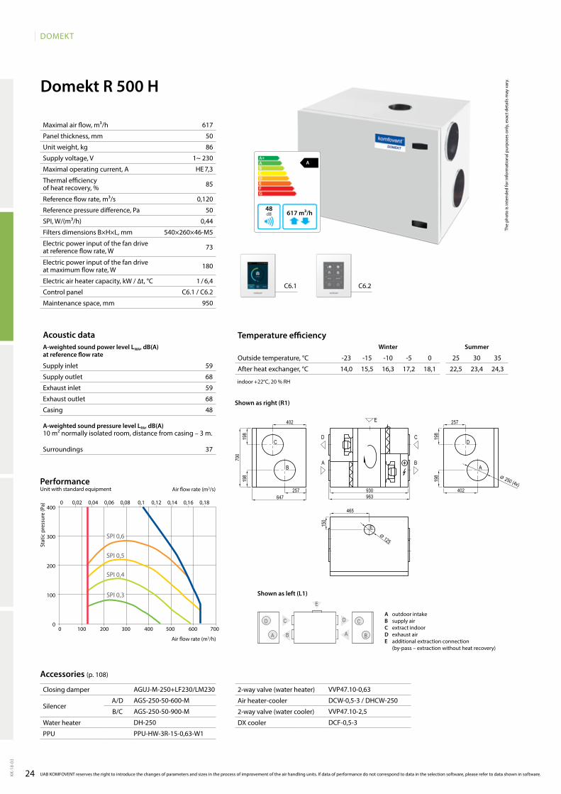
Domekt R 500 H
A
617 m³/h48
59
68
59
68
48
37
617
50
86
1~ 230
HE 7,3
85
0,120
50
0,44
540×260×46-M5
73
180
1 / 6,4
C6.1 / C6.2
950
C6.1 C6.2
14,0 15,5 16,3 17,2 18,1 22,5 23,4 24,3
AGUJ-M-250+LF230/LM230
AGS-250-50-600-M
AGS-250-50-900-M
DH-250
PPU-HW-3R-15-0,63-W1
VVP47.10-0,63
DCW-0,5-3 / DHCW-250
VVP47.10-2,5
DCF-0,5-3
D
A
C
B
DC
AB
E
Domekt_R_500_R1
C
E
B
D
A
E
A
D C
B
930963647
700
402
257
198
198
402
257
198
198
465
150
⌀ 125
⌀ 250 (4x)
400
300
200
100
0
0 0,02 0,04 0,06 0,08 0,1 0,12 0,14 0,16 0,18
0 100 200 300 400 500 600 700
SPI 0,3
SPI 0,4
SPI 0,5
SPI 0,6
Acoustic dataA-weighted sound power level LwA, dB(A)at reference flow rate
Supply inlet
Supply outlet
Exhaust inlet
Exhaust outlet
Casing
A-weighted sound pressure level LPA, dB(A) 10 m² normally isolated room, distance from casing – 3 m.
Surroundings
Maximal air flow, m³/h
Panel thickness, mm
Unit weight, kg
Supply voltage, V
Maximal operating current, A
Thermal efficiency of heat recovery, %
Reference flow rate, m³/s
Reference pressure difference, Pa
SPI, W/(m³/h)
Filters dimensions B×H×L, mm
Electric power input of the fan drive at reference flow rate, W
Electric power input of the fan drive at maximum flow rate, W
Electric air heater capacity, kW / ∆t, °C
Control panel
Maintenance space, mm
Stat
ic p
ress
ure
(Pa)
Air flow rate (m3/s)
Air flow rate (m3/h)
PerformanceUnit with standard equipment
UAB KOMFOVENT reserves the right to introduce the changes of parameters and sizes in the process of improvement of the air handling units. If data of performance do not correspond to data in the selection software, please refer to data shown in software.
Accessories (p. 108)
Temperature efficiencywinter Summer
Outside temperature, °C -23 -15 -10 -5 0 25 30 35
After heat exchanger, °C
indoor +22°C, 20 % RH
The
phot
o is
inte
nded
for i
nfor
mat
iona
l pur
pose
s on
ly, e
xact
det
ails
may
var
y.
Shown as right (R1)
Shown as left (L1)
A outdoor intakeB supply airC extract indoorD exhaust airE additional extraction connection
(by-pass – extraction without heat recovery)
Closing damper
SilencerA/D
B/C
Water heater
PPU
2-way valve (water heater)
Air heater-cooler
2-way valve (water cooler)
DX cooler
25
DOMEKT
KK-1
8-03
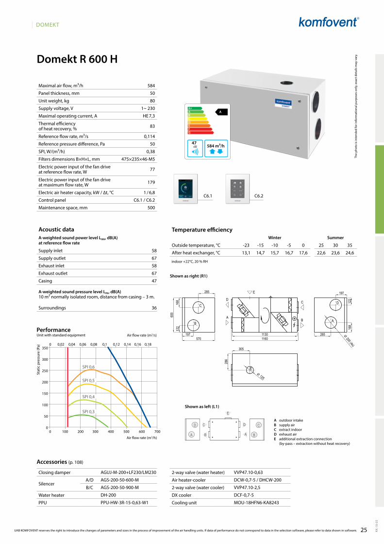
Domekt R 600 H
58
67
58
67
47
36
584
50
80
1~ 230
HE 7,3
83
0,114
50
0,38
475×235×46-M5
77
179
1 / 6,8
C6.1 / C6.2
500
A
584 m³/h47
C6.1 C6.2
13,1 14,7 15,7 16,7 17,6 22,6 23,6 24,6
AGUJ-M-200+LF230/LM230
AGS-200-50-600-M
AGS-200-50-900-M
DH-200
PPU-HW-3R-15-0,63-W1
VVP47.10-0,63
DCW-0,7-5 / DHCW-200
VVP47.10-2,5
DCF-0,7-5
MOU-18HFN6-KA8243
D
A
C
B
DC
AB
E
0 100 200 300 400 500 600 700
350
300
250
200
150
100
50
0
0 0,02 0,04 0,06 0,08 0,1 0,12 0,14 0,16 0,18
SPI 0,3
SPI 0,4
SPI 0,5
SPI 0,6
Domekt_R_600_R1
E
D
A
C
B
C
B
D
A
E
11301160
285
122
168
⌀ 200 (4x)
197285
122
168
197
600
305
286
570
⌀ 125
UAB KOMFOVENT reserves the right to introduce the changes of parameters and sizes in the process of improvement of the air handling units. If data of performance do not correspond to data in the selection software, please refer to data shown in software.
Acoustic dataA-weighted sound power level LwA, dB(A)at reference flow rate
Supply inlet
Supply outlet
Exhaust inlet
Exhaust outlet
Casing
A-weighted sound pressure level LPA, dB(A) 10 m² normally isolated room, distance from casing – 3 m.
Surroundings
Maximal air flow, m³/h
Panel thickness, mm
Unit weight, kg
Supply voltage, V
Maximal operating current, A
Thermal efficiency of heat recovery, %
Reference flow rate, m³/s
Reference pressure difference, Pa
SPI, W/(m³/h)
Filters dimensions B×H×L, mm
Electric power input of the fan drive at reference flow rate, W
Electric power input of the fan drive at maximum flow rate, W
Electric air heater capacity, kW / ∆t, °C
Control panel
Maintenance space, mm
Stat
ic p
ress
ure
(Pa)
Air flow rate (m3/s)
Air flow rate (m3/h)
PerformanceUnit with standard equipment
Accessories (p. 108)
Temperature efficiencyWinter Summer
Outside temperature, °C -23 -15 -10 -5 0 25 30 35
After heat exchanger, °C
indoor +22°C, 20 % RH
The
phot
o is
inte
nded
for i
nfor
mat
iona
l pur
pose
s on
ly, e
xact
det
ails
may
var
y.
Shown as right (R1)
Shown as left (L1)
A outdoor intakeB supply airC extract indoorD exhaust airE additional extraction connection
(by-pass – extraction without heat recovery)
Closing damper
SilencerA/D
B/C
Water heater
PPU
2-way valve (water heater)
Air heater-cooler
2-way valve (water cooler)
DX cooler
Cooling unit
26
DOMEKT
KK-1
8-03
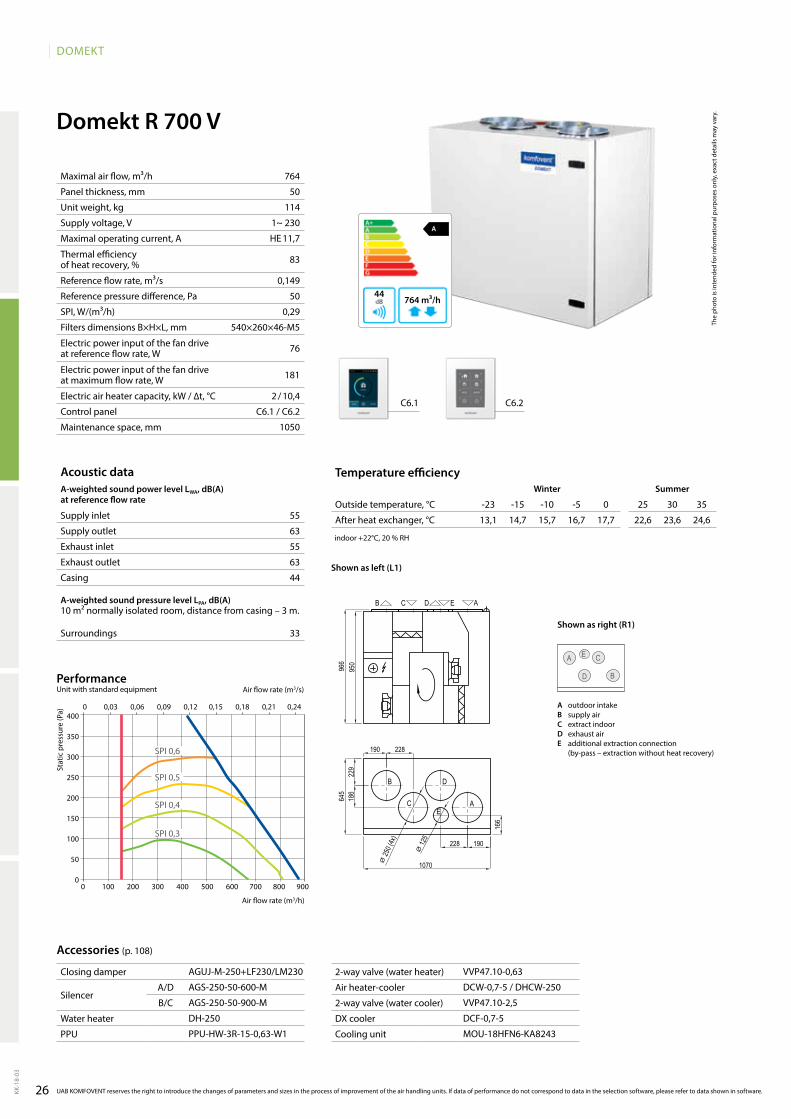
Domekt R 700 V
A
764 m³/h44
764
50
114
1~ 230
HE 11,7
83
0,149
50
0,29
540×260×46-M5
76
181
2 / 10,4
C6.1 / C6.2
1050
55
63
55
63
44
33
C6.1 C6.2
13,1 14,7 15,7 16,7 17,7 22,6 23,6 24,6
AGUJ-M-250+LF230/LM230
AGS-250-50-600-M
AGS-250-50-900-M
DH-250
PPU-HW-3R-15-0,63-W1
VVP47.10-0,63
DCW-0,7-5 / DHCW-250
VVP47.10-2,5
DCF-0,7-5
MOU-18HFN6-KA8243
D
A
B
CE
400
350
300
250
200
150
100
50
00 100 200 300 400 500 600 700 800 900
0 0,03 0,06 0,09 0,12 0,15 0,18 0,21 0,24
SPI 0,3
SPI 0,4
SPI 0,5
SPI 0,6
Domekt_R_700_L1
AE
C
B D
B C ED A
966
950
645
1070
190228
229
186
166
⌀ 12
5
190 228
⌀ 25
0 (4x
)
Acoustic dataA-weighted sound power level LwA, dB(A)at reference flow rate
Supply inlet
Supply outlet
Exhaust inlet
Exhaust outlet
Casing
A-weighted sound pressure level LPA, dB(A) 10 m² normally isolated room, distance from casing – 3 m.
Surroundings
Maximal air flow, m³/h
Panel thickness, mm
Unit weight, kg
Supply voltage, V
Maximal operating current, A
Thermal efficiency of heat recovery, %
Reference flow rate, m³/s
Reference pressure difference, Pa
SPI, W/(m³/h)
Filters dimensions B×H×L, mm
Electric power input of the fan drive at reference flow rate, W
Electric power input of the fan drive at maximum flow rate, W
Electric air heater capacity, kW / ∆t, °C
Control panel
Maintenance space, mm
Stat
ic p
ress
ure
(Pa)
Air flow rate (m3/s)
Air flow rate (m3/h)
PerformanceUnit with standard equipment
UAB KOMFOVENT reserves the right to introduce the changes of parameters and sizes in the process of improvement of the air handling units. If data of performance do not correspond to data in the selection software, please refer to data shown in software.
Accessories (p. 108)
Temperature efficiencywinter Summer
Outside temperature, °C -23 -15 -10 -5 0 25 30 35
After heat exchanger, °C
indoor +22°C, 20 % RH
The
phot
o is
inte
nded
for i
nfor
mat
iona
l pur
pose
s on
ly, e
xact
det
ails
may
var
y.
Shown as left (L1)
Shown as right (R1)
A outdoor intakeB supply airC extract indoorD exhaust airE additional extraction connection
(by-pass – extraction without heat recovery)
Closing damper
SilencerA/D
B/C
Water heater
PPU
2-way valve (water heater)
Air heater-cooler
2-way valve (water cooler)
DX cooler
Cooling unit
27
DOMEKT
KK-1
8-03
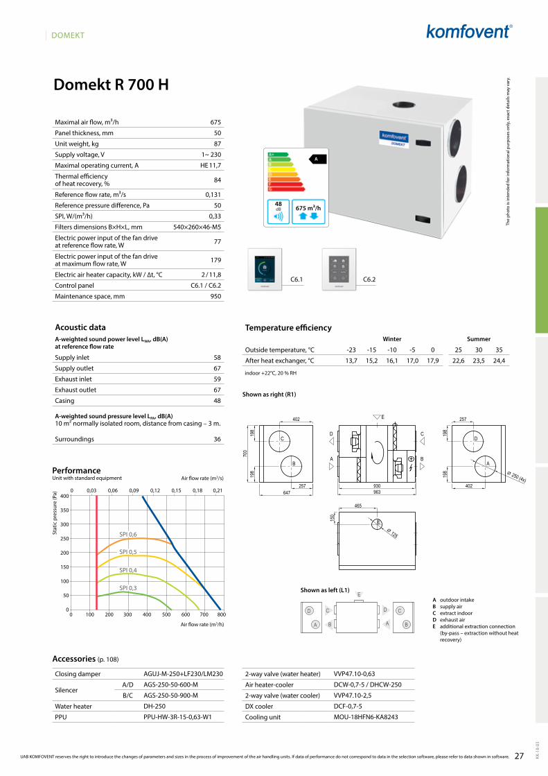
Domekt R 700 H
A
675 m³/h48
58
67
59
67
48
36
675
50
87
1~ 230
HE 11,7
84
0,131
50
0,33
540×260×46-M5
77
179
2 / 11,8
C6.1 / C6.2
950
C6.1 C6.2
13,7 15,2 16,1 17,0 17,9 22,6 23,5 24,4
AGUJ-M-250+LF230/LM230
AGS-250-50-600-M
AGS-250-50-900-M
DH-250
PPU-HW-3R-15-0,63-W1
VVP47.10-0,63
DCW-0,7-5 / DHCW-250
VVP47.10-2,5
DCF-0,7-5
MOU-18HFN6-KA8243
D
A
C
B
DC
AB
E
0 100 200 300 400 500 600 700 800
400
350
300
250
200
150
100
50
0
0 0,03 0,06 0,09 0,12 0,15 0,18 0,21
SPI 0,3
SPI 0,4
SPI 0,5
SPI 0,6
Domekt_R_700_R1
C
E
B
D
A
E
A
D C
B
930963647
700
402
257
198
198
402
257
198
198
465
150
⌀ 125
⌀ 250 (4x)
UAB KOMFOVENT reserves the right to introduce the changes of parameters and sizes in the process of improvement of the air handling units. If data of performance do not correspond to data in the selection software, please refer to data shown in software.
Acoustic dataA-weighted sound power level LwA, dB(A)at reference flow rate
Supply inlet
Supply outlet
Exhaust inlet
Exhaust outlet
Casing
A-weighted sound pressure level LPA, dB(A) 10 m² normally isolated room, distance from casing – 3 m.
Surroundings
Maximal air flow, m³/h
Panel thickness, mm
Unit weight, kg
Supply voltage, V
Maximal operating current, A
Thermal efficiency of heat recovery, %
Reference flow rate, m³/s
Reference pressure difference, Pa
SPI, W/(m³/h)
Filters dimensions B×H×L, mm
Electric power input of the fan drive at reference flow rate, W
Electric power input of the fan drive at maximum flow rate, W
Electric air heater capacity, kW / ∆t, °C
Control panel
Maintenance space, mm
Stat
ic p
ress
ure
(Pa)
Air flow rate (m3/s)
Air flow rate (m3/h)
PerformanceUnit with standard equipment
Accessories (p. 108)
Temperature efficiencyWinter Summer
Outside temperature, °C -23 -15 -10 -5 0 25 30 35
After heat exchanger, °C
indoor +22°C, 20 % RH
The
phot
o is
inte
nded
for i
nfor
mat
iona
l pur
pose
s on
ly, e
xact
det
ails
may
var
y.
Shown as right (R1)
Shown as left (L1)A outdoor intakeB supply airC extract indoorD exhaust airE additional extraction connection
(by-pass – extraction without heat recovery)
Closing damper
SilencerA/D
B/C
Water heater
PPU
2-way valve (water heater)
Air heater-cooler
2-way valve (water cooler)
DX cooler
Cooling unit
28
DOMEKT
KK-1
8-03
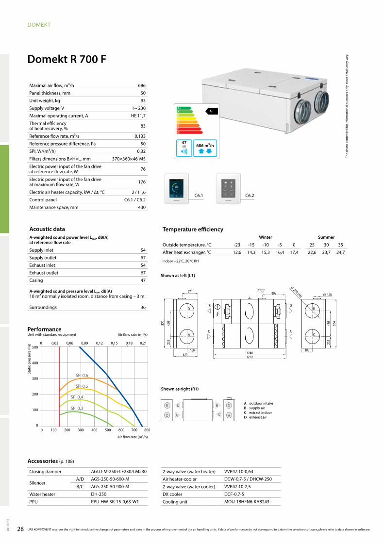
Domekt R 700 F
A
686 m³/h47
686
50
93
1~ 230
HE 11,7
83
0,133
50
0,32
370×360×46-M5
76
176
2 / 11,6
C6.1 / C6.2
430
54
67
54
67
47
36
C6.1 C6.2
12,6 14,3 15,3 16,4 17,4 22,6 23,7 24,7
AGUJ-M-250+LF230/LM230
AGS-250-50-600-M
AGS-250-50-900-M
DH-250
PPU-HW-3R-15-0,63-W1
VVP47.10-0,63
DCW-0,7-5 / DHCW-250
VVP47.10-2,5
DCF-0,7-5
MOU-18HFN6-KA8243
0 100 200 300 400 500 600 700 800
500
400
300
200
100
0
0 0,03 0,06 0,09 0,12 0,15 0,18 0,21
SPI 0,3
SPI 0,6
SPI 0,5
SPI 0,4
D
A
Domekt_R_700_L1
B
C
E
B
C
D
A
420
202
450
18612401272
271
870
399
202
450
186
854
⌀ 250 (4x) ⌀ 125
Acoustic dataA-weighted sound power level LwA, dB(A)at reference flow rate
Supply inlet
Supply outlet
Exhaust inlet
Exhaust outlet
Casing
A-weighted sound pressure level LPA, dB(A) 10 m² normally isolated room, distance from casing – 3 m.
Surroundings
Maximal air flow, m³/h
Panel thickness, mm
Unit weight, kg
Supply voltage, V
Maximal operating current, A
Thermal efficiency of heat recovery, %
Reference flow rate, m³/s
Reference pressure difference, Pa
SPI, W/(m³/h)
Filters dimensions B×H×L, mm
Electric power input of the fan drive at reference flow rate, W
Electric power input of the fan drive at maximum flow rate, W
Electric air heater capacity, kW / ∆t, °C
Control panel
Maintenance space, mm
Stat
ic p
ress
ure
(Pa)
Air flow rate (m3/s)
Air flow rate (m3/h)
PerformanceUnit with standard equipment
UAB KOMFOVENT reserves the right to introduce the changes of parameters and sizes in the process of improvement of the air handling units. If data of performance do not correspond to data in the selection software, please refer to data shown in software.
Accessories (p. 108)
Temperature efficiencywinter Summer
Outside temperature, °C -23 -15 -10 -5 0 25 30 35
After heat exchanger, °C
indoor +22°C, 20 % RH
The
phot
o is
inte
nded
for i
nfor
mat
iona
l pur
pose
s on
ly, e
xact
det
ails
may
var
y.
Shown as left (L1)
D
A C
B D
C A
B
Shown as right (R1)
A outdoor intakeB supply airC extract indoorD exhaust air
Closing damper
SilencerA/D
B/C
Water heater
PPU
2-way valve (water heater)
Air heater-cooler
2-way valve (water cooler)
DX cooler
Cooling unit
29
DOMEKT
KK-1
8-03
Domekt CF
0 0,03 0,06 0,08 0,11 0,14 0,17 0,19 0,22 0,25 0,28
0 100 200 300 400 500 600 700 800 900 1000
700
500
400
250
Air handling units with a counterflow plate heat exchanger
Air flow, m³/s
Air flow, m³/h
Sizes of Domekt CF units
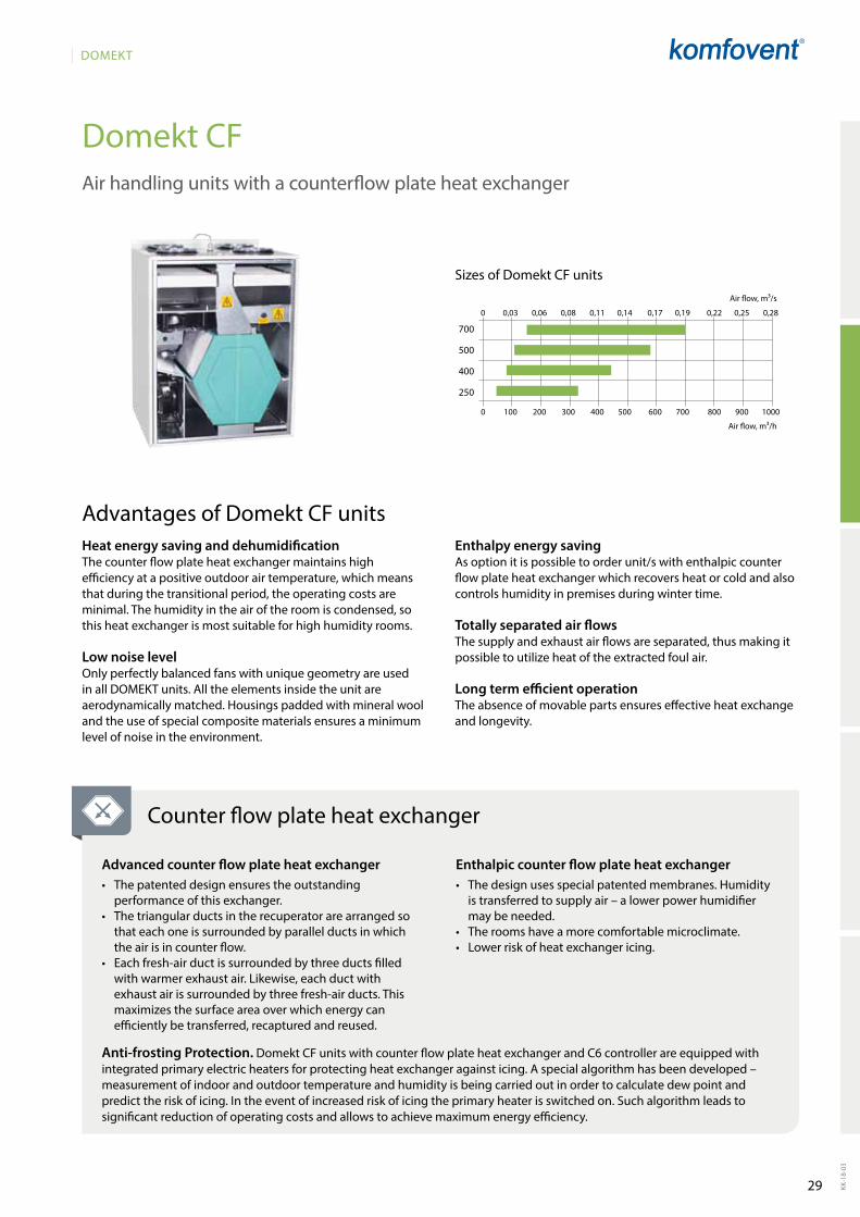
Heat energy saving and dehumidification The counter flow plate heat exchanger maintains high efficiency at a positive outdoor air temperature, which means that during the transitional period, the operating costs are minimal. The humidity in the air of the room is condensed, so this heat exchanger is most suitable for high humidity rooms.
Low noise levelOnly perfectly balanced fans with unique geometry are used in all DOMEKT units. All the elements inside the unit are aerodynamically matched. Housings padded with mineral wool and the use of special composite materials ensures a minimum level of noise in the environment.
Advantages of Domekt CF unitsEnthalpy energy savingAs option it is possible to order unit/s with enthalpic counter flow plate heat exchanger which recovers heat or cold and also controls humidity in premises during winter time.
Totally separated air flows The supply and exhaust air flows are separated, thus making it possible to utilize heat of the extracted foul air.
Long term efficient operationThe absence of movable parts ensures effective heat exchange and longevity.
Counter flow plate heat exchanger
Advanced counter flow plate heat exchanger • Thepatenteddesignensurestheoutstanding
performance of this exchanger.• Thetriangularductsintherecuperatorarearrangedso
that each one is surrounded by parallel ducts in which the air is in counter flow.
• Eachfresh-airductissurroundedbythreeductsfilledwith warmer exhaust air. Likewise, each duct with exhaust air is surrounded by three fresh-air ducts. This maximizes the surface area over which energy can efficiently be transferred, recaptured and reused.
Enthalpic counter flow plate heat exchanger • Thedesignusesspecialpatentedmembranes.Humidity
is transferred to supply air – a lower power humidifier may be needed.
• Theroomshaveamorecomfortablemicroclimate.• Lowerriskofheatexchangericing.
Anti-frosting Protection. Domekt CF units with counter flow plate heat exchanger and C6 controller are equipped with integrated primary electric heaters for protecting heat exchanger against icing. A special algorithm has been developed – measurement of indoor and outdoor temperature and humidity is being carried out in order to calculate dew point and predict the risk of icing. In the event of increased risk of icing the primary heater is switched on. Such algorithm leads to significant reduction of operating costs and allows to achieve maximum energy efficiency.
30
DOMEKT
KK-1
8-03
UAB KOMFOVENT reserves the right to introduce the changes of parameters and sizes in the process of improvement of the air handling units.
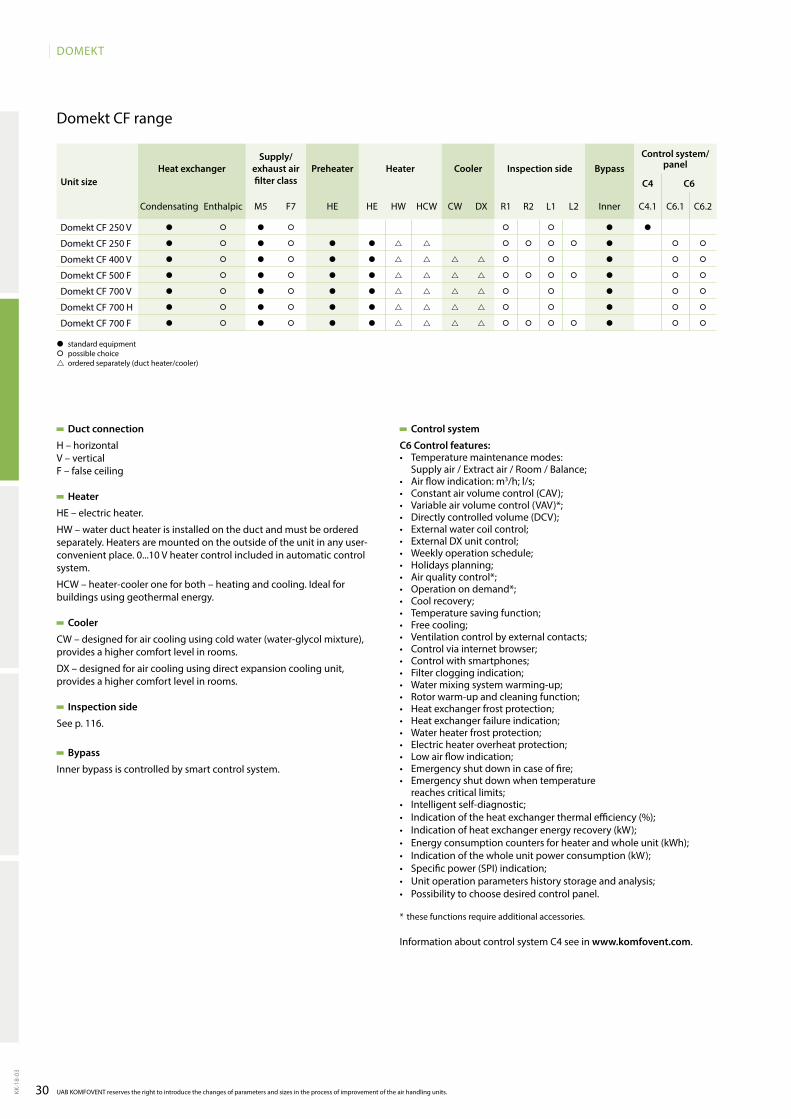
Domekt CF range
Duct connection
H – horizontalV – verticalF – false ceiling
Heater
HE – electric heater.
HW – water duct heater is installed on the duct and must be ordered separately. Heaters are mounted on the outside of the unit in any user-convenient place. 0...10 V heater control included in automatic control system.
HCW – heater-cooler one for both – heating and cooling. Ideal for buildings using geothermal energy.
Cooler
CW – designed for air cooling using cold water (water-glycol mixture), provides a higher comfort level in rooms.
DX – designed for air cooling using direct expansion cooling unit, provides a higher comfort level in rooms.
Inspection side
See p. 116.
Bypass
Inner bypass is controlled by smart control system.
� standard equipment� possible choice ordered separately (duct heater/cooler)
Control system
C6 Control features:• Temperature maintenance modes:
Supply air / Extract air / Room / Balance;• Air flow indication: m3/h; l/s;• Constant air volume control (CAV);• Variable air volume control (VAV)*;• Directly controlled volume (DCV);• External water coil control;• External DX unit control;• Weekly operation schedule;• Holidays planning;• Air quality control*;• Operation on demand*;• Cool recovery;• Temperature saving function;• Free cooling;• Ventilation control by external contacts;• Control via internet browser;• Control with smartphones;• Filter clogging indication;• Water mixing system warming-up;• Rotor warm-up and cleaning function;• Heat exchanger frost protection;• Heat exchanger failure indication;• Water heater frost protection;• Electric heater overheat protection;• Low air flow indication;• Emergency shut down in case of fire;• Emergency shut down when temperature
reaches critical limits;• Intelligent self-diagnostic;• Indication of the heat exchanger thermal efficiency (%);• Indication of heat exchanger energy recovery (kW);• Energy consumption counters for heater and whole unit (kWh);• Indication of the whole unit power consumption (kW);• Specific power (SPI) indication;• Unit operation parameters history storage and analysis;• Possibility to choose desired control panel.
* these functions require additional accessories.
Information about control system C4 see in www.komfovent.com.
Unit sizeHeat exchanger
Supply/exhaust air filter class
Preheater Heater Cooler Inspection side BypassControl system/
panel
C4 C6
Condensating Enthalpic M5 F7 HE HE HW HCW CW DX R1 R2 L1 L2 Inner C4.1 C6.1 C6.2
Domekt CF 250 V � � � � � � � �
Domekt CF 250 F � � � � � � � � � � � � �
Domekt CF 400 V � � � � � � � � � � �
Domekt CF 500 F � � � � � � � � � � � � �
Domekt CF 700 V � � � � � � � � � � �
Domekt CF 700 H � � � � � � � � � � �
Domekt CF 700 F � � � � � � � � � � � � �
31
DOMEKT
KK-1
8-03
A
D
C
Domekt_CF_250_R1
B
D A B C
700
135
747
225
105 385 510
15
715
595
⌀ 125 (4x)
A
211 m³/h49
A
DB
C
48
70
53
70
49
38
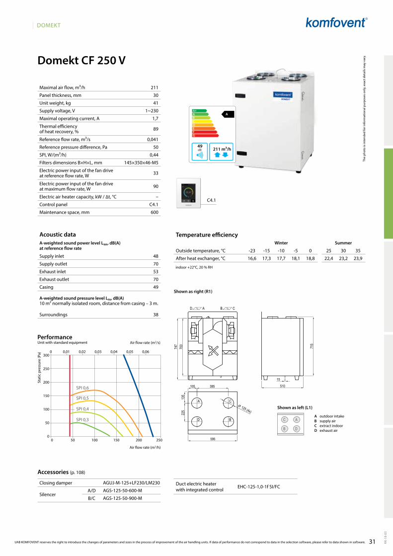
Domekt CF 250 V
211
30
41
1~230
1,7
89
0,041
50
0,44
145×350×46-M5
33
90
–
C4.1
600
C4.1
16,6 17,3 17,7 18,1 18,8 22,4 23,2 23,9
AGUJ-M-125+LF230/LM230
AGS-125-50-600-M
AGS-125-50-900-M
EHC-125-1,0-1f SI/FC
UAB KOMFOVENT reserves the right to introduce the changes of parameters and sizes in the process of improvement of the air handling units. If data of performance do not correspond to data in the selection software, please refer to data shown in software.
Acoustic dataA-weighted sound power level LwA, dB(A)at reference flow rate
Supply inlet
Supply outlet
Exhaust inlet
Exhaust outlet
Casing
A-weighted sound pressure level LPA, dB(A) 10 m² normally isolated room, distance from casing – 3 m.
Surroundings
Maximal air flow, m³/h
Panel thickness, mm
Unit weight, kg
Supply voltage, V
Maximal operating current, A
Thermal efficiency of heat recovery, %
Reference flow rate, m³/s
Reference pressure difference, Pa
SPI, W/(m³/h)
Filters dimensions B×H×L, mm
Electric power input of the fan drive at reference flow rate, W
Electric power input of the fan drive at maximum flow rate, W
Electric air heater capacity, kW / ∆t, °C
Control panel
Maintenance space, mm
Stat
ic p
ress
ure
(Pa)
Air flow rate (m3/s)
Air flow rate (m3/h)
PerformanceUnit with standard equipment
Accessories (p. 108)
Temperature efficiencyWinter Summer
Outside temperature, °C -23 -15 -10 -5 0 25 30 35
After heat exchanger, °C
indoor +22°C, 20 % RH
The
phot
o is
inte
nded
for i
nfor
mat
iona
l pur
pose
s on
ly, e
xact
det
ails
may
var
y.
Shown as left (L1)
Shown as right (R1)
0 0,01 0,02 0,03 0,04 0,05 0,06300
250
200
150
100
50
00 50 100 150 200 250
SPI 0,4
SPI 0,5
SPI 0,6
SPI 0,3A outdoor intakeB supply airC extract indoorD exhaust air
Closing damper
SilencerA/D
B/C
Duct electric heater with integrated control
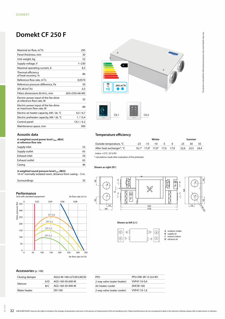
32
DOMEKT
KK-1
8-03
AGUJ-M-160+LF230/LM230
AGS-160-50-600-M
AGS-160-50-900-M
DH-160
PPU-HW-3R-15-0,4-W1
VVP47.10-0,4
DHCW-160
VVP47.10-1,6
C6.1 C6.2
A
295 m³/h46
16,1* 17,0* 17,0* 17,0 17,9 22,6 23,5 24,4
295
30
52
1~230
8,3
86
0,0574
50
0,3
265×250×46-M5
32
89
0,5 / 6,7
1 / 13,4
C6.1 / 6.2
300
53
65
54
65
46
35
Domekt CF 250 F
C
BD
A A
B
C
D
0 0,02 0,04 0,06 0,08350
300
250
200
150
100
50
00 50 100 150 200 250 300 350
SPI 0,4
SPI 0,5
SPI 0,6
SPI 0,3
Domekt_CF_250_R1
B
C
D
A
B
C
D
A
12501278
162
142
294
162
192
134 134
604
15
⌀160 (4x)
The
phot
o is
inte
nded
for i
nfor
mat
iona
l pur
pose
s on
ly, e
xact
det
ails
may
var
y.
Acoustic dataA-weighted sound power level LwA, dB(A)at reference flow rate
Supply inlet
Supply outlet
Exhaust inlet
Exhaust outlet
Casing
A-weighted sound pressure level LPA, dB(A) 10 m² normally isolated room, distance from casing – 3 m.
Surroundings
Maximal air flow, m³/h
Panel thickness, mm
Unit weight, kg
Supply voltage, V
Maximal operating current, A
Thermal efficiency of heat recovery, %
Reference flow rate, m³/s
Reference pressure difference, Pa
SPI, W/(m³/h)
Filters dimensions B×H×L, mm
Electric power input of the fan drive at reference flow rate, W
Electric power input of the fan drive at maximum flow rate, W
Electric air heater capacity, kW / ∆t, °C
Electric preheater capacity, kW / ∆t, °C
Control panel
Maintenance space, mm
Stat
ic p
ress
ure
(Pa)
Air flow rate (m3/s)
Air flow rate (m3/h)
PerformanceUnit with standard equipment
Temperature efficiencywinter Summer
Outside temperature, °C -23 -15 -10 -5 0 25 30 35
After heat exchanger*, °C
indoor +22°C, 20 % RH
* calculations made after evaluation of the preheater.
Accessories (p. 108)
UAB KOMFOVENT reserves the right to introduce the changes of parameters and sizes in the process of improvement of the air handling units. If data of performance do not correspond to data in the selection software, please refer to data shown in software.
Shown as left (L1)
Shown as right (R1)
A outdoor intakeB supply airC extract indoorD exhaust air
Closing damper
SilencerA/D
B/C
Water heater
PPU
2-way valve (water heater)
Air heater-cooler
2-way valve (water cooler)
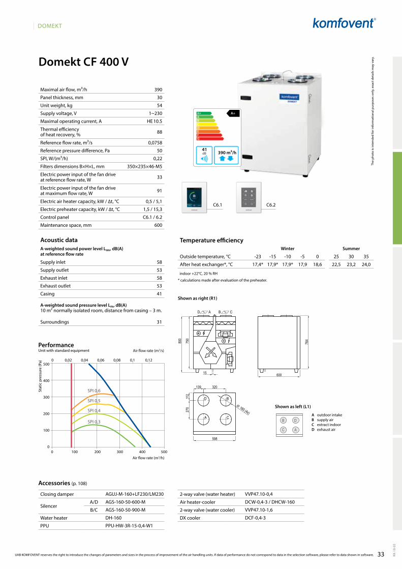
33
DOMEKT
KK-1
8-03
Domekt_CF_400_R1
D A B C
D B
A C
270
750
800
598
15
112
139 320
600
764
⌀ 160 (4x)
AGUJ-M-160+LF230/LM230
AGS-160-50-600-M
AGS-160-50-900-M
DH-160
PPU-HW-3R-15-0,4-W1
VVP47.10-0,4
DCW-0,4-3 / DHCW-160
VVP47.10-1,6
DCF-0,4-3
D
AC
B
A+
390 m³/h41
C6.1 C6.2
SPI 0,4
SPI 0,5
SPI 0,6
SPI 0,3
390
30
54
1~230
HE 10.5
88
0,0758
50
0,22
350×235×46-M5
33
91
0,5 / 5,1
1,5 / 15,3
C6.1 / 6.2
600
Domekt CF 400 V
0 100 200 300 400 500
500
400
300
200
100
0
0 0,02 0,04 0,06 0,08 0,1 0,12
The
phot
o is
inte
nded
for i
nfor
mat
iona
l pur
pose
s on
ly, e
xact
det
ails
may
var
y.
Acoustic dataA-weighted sound power level LwA, dB(A)at reference flow rate
Supply inlet
Supply outlet
Exhaust inlet
Exhaust outlet
Casing
A-weighted sound pressure level LPA, dB(A) 10 m² normally isolated room, distance from casing – 3 m.
Surroundings
Maximal air flow, m³/h
Panel thickness, mm
Unit weight, kg
Supply voltage, V
Maximal operating current, A
Thermal efficiency of heat recovery, %
Reference flow rate, m³/s
Reference pressure difference, Pa
SPI, W/(m³/h)
Filters dimensions B×H×L, mm
Electric power input of the fan drive at reference flow rate, W
Electric power input of the fan drive at maximum flow rate, W
Electric air heater capacity, kW / ∆t, °C
Electric preheater capacity, kW / ∆t, °C
Control panel
Maintenance space, mm
Stat
ic p
ress
ure
(Pa)
Air flow rate (m3/s)
Air flow rate (m3/h)
PerformanceUnit with standard equipment
Temperature efficiencyWinter Summer
Outside temperature, °C -23 -15 -10 -5 0 25 30 35
After heat exchanger*, °C
indoor +22°C, 20 % RH
* calculations made after evaluation of the preheater.
Accessories (p. 108)
UAB KOMFOVENT reserves the right to introduce the changes of parameters and sizes in the process of improvement of the air handling units. If data of performance do not correspond to data in the selection software, please refer to data shown in software.
58
53
58
53
41
31
17,4* 17,9* 17,9* 17,9 18,6 22,5 23,2 24,0
Shown as left (L1)
Shown as right (R1)
A outdoor intakeB supply airC extract indoorD exhaust air
Closing damper
SilencerA/D
B/C
Water heater
PPU
2-way valve (water heater)
Air heater-cooler
2-way valve (water cooler)
DX cooler
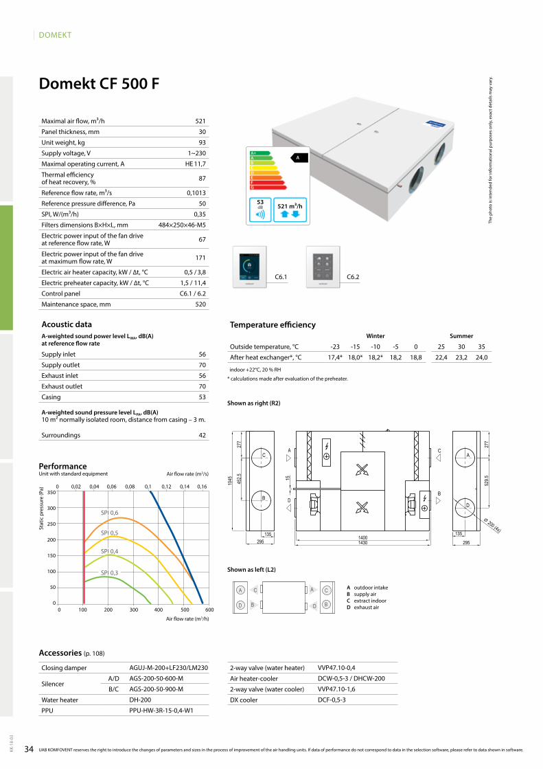
34
DOMEKT
KK-1
8-03
A
521 m³/h53
521
30
93
1~230
HE 11,7
87
0,1013
50
0,35
484×250×46-M5
67
171
0,5 / 3,8
1,5 / 11,4
C6.1 / 6.2
520
56
70
56
70
53
42
17,4* 18,0* 18,2* 18,2 18,8 22,4 23,2 24,0
AGUJ-M-200+LF230/LM230
AGS-200-50-600-M
AGS-200-50-900-M
DH-200
PPU-HW-3R-15-0,4-W1
VVP47.10-0,4
DCW-0,5-3 / DHCW-200
VVP47.10-1,6
DCF-0,5-3
C6.1 C6.2
Domekt CF 500 F
B
C A
D D
C
B
A
0 100 200 300 400 500 600
350
300
250
200
150
100
50
0
0 0,02 0,04 0,06 0,08 0,1 0,12 0,14 0,16
SPI 0,4
SPI 0,5
SPI 0,6
SPI 0,3
Domekt_CF_500_R2
C
B
A
DD
A
B
C
1400
452.5
295
277
1351430
1045
295
277
529.515
135
⌀ 200 (4x)
The
phot
o is
inte
nded
for i
nfor
mat
iona
l pur
pose
s on
ly, e
xact
det
ails
may
var
y.
Acoustic dataA-weighted sound power level LwA, dB(A)at reference flow rate
Supply inlet
Supply outlet
Exhaust inlet
Exhaust outlet
Casing
A-weighted sound pressure level LPA, dB(A) 10 m² normally isolated room, distance from casing – 3 m.
Surroundings
Maximal air flow, m³/h
Panel thickness, mm
Unit weight, kg
Supply voltage, V
Maximal operating current, A
Thermal efficiency of heat recovery, %
Reference flow rate, m³/s
Reference pressure difference, Pa
SPI, W/(m³/h)
Filters dimensions B×H×L, mm
Electric power input of the fan drive at reference flow rate, W
Electric power input of the fan drive at maximum flow rate, W
Electric air heater capacity, kW / ∆t, °C
Electric preheater capacity, kW / ∆t, °C
Control panel
Maintenance space, mm
Stat
ic p
ress
ure
(Pa)
Air flow rate (m3/s)
Air flow rate (m3/h)
PerformanceUnit with standard equipment
Temperature efficiencywinter Summer
Outside temperature, °C -23 -15 -10 -5 0 25 30 35
After heat exchanger*, °C
indoor +22°C, 20 % RH
* calculations made after evaluation of the preheater.
Accessories (p. 108)
UAB KOMFOVENT reserves the right to introduce the changes of parameters and sizes in the process of improvement of the air handling units. If data of performance do not correspond to data in the selection software, please refer to data shown in software.
Shown as left (L2)
Shown as right (R2)
A outdoor intakeB supply airC extract indoorD exhaust air
Closing damper
SilencerA/D
B/C
Water heater
PPU
2-way valve (water heater)
Air heater-cooler
2-way valve (water cooler)
DX cooler
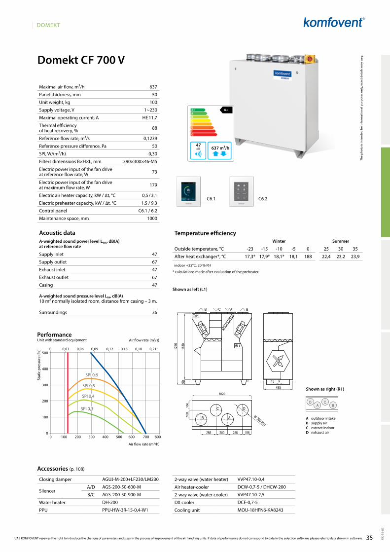
35
DOMEKT
KK-1
8-03
0 100 200 300 400 500 600 700 800
0 0,03 0,06 0,09 0,12 0,15 0,18 0,21500
400
300
200
100
0
637
50
100
1~230
HE 11,7
88
0,1239
50
0,30
390×300×46-M5
73
179
0,5 / 3,1
1,5 / 9,3
C6.1 / 6.2
1000
47
67
47
67
47
36
D A
C B
17,3* 17,9* 18,1* 18,1 188 22,4 23,2 23,9
AGUJ-M-200+LF230/LM230
AGS-200-50-600-M
AGS-200-50-900-M
DH-200
PPU-HW-3R-15-0,4-W1
VVP47.10-0,4
DCW-0,7-5 / DHCW-200
VVP47.10-2,5
DCF-0,7-5
MOU-18HFN6-KA8243
C6.1 C6.2
SPI 0,4
SPI 0,5
SPI 0,6
SPI 0,3
Domekt CF 700 V
1130
90
1236
155
160
166
1020
255200255
49515
⌀ 200 (4x)
Domekt_CF_700_L1
D
A
C
B
BACB
A+
637 m³/h47
The
phot
o is
inte
nded
for i
nfor
mat
iona
l pur
pose
s on
ly, e
xact
det
ails
may
var
y.
Acoustic dataA-weighted sound power level LwA, dB(A)at reference flow rate
Supply inlet
Supply outlet
Exhaust inlet
Exhaust outlet
Casing
A-weighted sound pressure level LPA, dB(A) 10 m² normally isolated room, distance from casing – 3 m.
Surroundings
Maximal air flow, m³/h
Panel thickness, mm
Unit weight, kg
Supply voltage, V
Maximal operating current, A
Thermal efficiency of heat recovery, %
Reference flow rate, m³/s
Reference pressure difference, Pa
SPI, W/(m³/h)
Filters dimensions B×H×L, mm
Electric power input of the fan drive at reference flow rate, W
Electric power input of the fan drive at maximum flow rate, W
Electric air heater capacity, kW / ∆t, °C
Electric preheater capacity, kW / ∆t, °C
Control panel
Maintenance space, mm
Stat
ic p
ress
ure
(Pa)
Air flow rate (m3/s)
Air flow rate (m3/h)
PerformanceUnit with standard equipment
Temperature efficiencyWinter Summer
Outside temperature, °C -23 -15 -10 -5 0 25 30 35
After heat exchanger*, °C
indoor +22°C, 20 % RH
* calculations made after evaluation of the preheater.
Accessories (p. 108)
UAB KOMFOVENT reserves the right to introduce the changes of parameters and sizes in the process of improvement of the air handling units. If data of performance do not correspond to data in the selection software, please refer to data shown in software.
Shown as right (R1)
Shown as left (L1)
A outdoor intakeB supply airC extract indoorD exhaust air
Closing damper
SilencerA/D
B/C
Water heater
PPU
2-way valve (water heater)
Air heater-cooler
2-way valve (water cooler)
DX cooler
Cooling unit
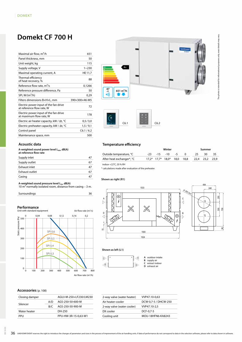
36
DOMEKT
KK-1
8-03
Domekt CF 700 H
651
50
115
1~230
HE 11,7
88
0,1266
50
0,29
390×300×46-M5
72
178
0,5 / 3,0
1,5 / 9,1
C6.1 / 6.2
500
47
67
47
67
47
36
B
A C
D
17,2* 17,7* 18,0* 18,0 18,8 22,4 23,2 23,9
AGUJ-M-250+LF230/LM230
AGS-250-50-600-M
AGS-250-50-900-M
DH-250
PPU-HW-3R-15-0,63-W1
VVP47.10-0,63
DCW-0,7-5 / DHCW-250
VVP47.10-2,5
DCF-0,7-5
MOU-18HFN6-KA8243
C6.1 C6.2
700
200
248494
1500
1533
300
15 90
⌀ 250 (4x)
1524
A
D
A
D
C
B
Domekt_CF_700_R1
A+
651 m³/h47
0 100 200 300 400 500 600 700 800
0 0,04 0,08 0,12 0,16 0,2500
400
300
200
100
0
SPI 0,4
SPI 0,5
SPI 0,6
SPI 0,3
The
phot
o is
inte
nded
for i
nfor
mat
iona
l pur
pose
s on
ly, e
xact
det
ails
may
var
y.
Acoustic dataA-weighted sound power level LwA, dB(A)at reference flow rate
Supply inlet
Supply outlet
Exhaust inlet
Exhaust outlet
Casing
A-weighted sound pressure level LPA, dB(A) 10 m² normally isolated room, distance from casing – 3 m.
Surroundings
Maximal air flow, m³/h
Panel thickness, mm
Unit weight, kg
Supply voltage, V
Maximal operating current, A
Thermal efficiency of heat recovery, %
Reference flow rate, m³/s
Reference pressure difference, Pa
SPI, W/(m³/h)
Filters dimensions B×H×L, mm
Electric power input of the fan drive at reference flow rate, W
Electric power input of the fan drive at maximum flow rate, W
Electric air heater capacity, kW / ∆t, °C
Electric preheater capacity, kW / ∆t, °C
Control panel
Maintenance space, mm
Stat
ic p
ress
ure
(Pa)
Air flow rate (m3/s)
Air flow rate (m3/h)
PerformanceUnit with standard equipment
Temperature efficiencywinter Summer
Outside temperature, °C -23 -15 -10 -5 0 25 30 35
After heat exchanger*, °C
indoor +22°C, 20 % RH
* calculations made after evaluation of the preheater.
Accessories (p. 108)
UAB KOMFOVENT reserves the right to introduce the changes of parameters and sizes in the process of improvement of the air handling units. If data of performance do not correspond to data in the selection software, please refer to data shown in software.
Shown as right (R1)
Shown as left (L1)
A outdoor intakeB supply airC extract indoorD exhaust air
Closing damper
SilencerA/D
B/C
Water heater
PPU
2-way valve (water heater)
Air heater-cooler
2-way valve (water cooler)
DX cooler
Cooling unit
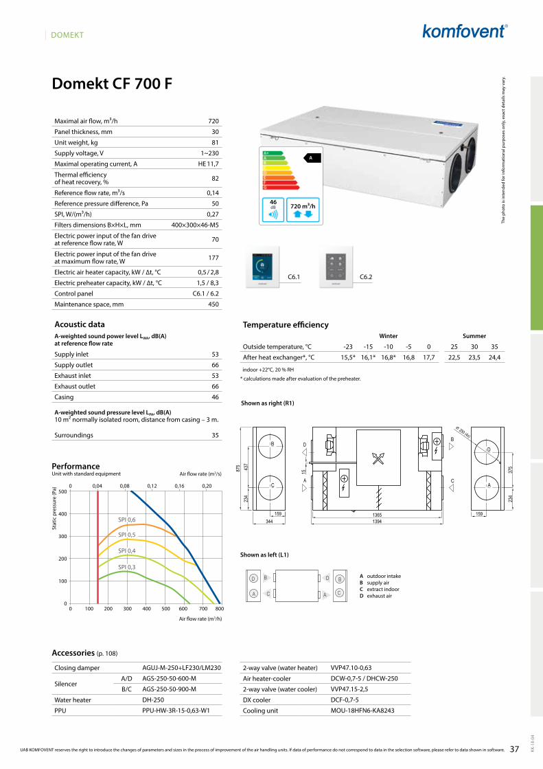
37
DOMEKT
KK-1
8-04
Domekt CF 700 F
A
720 m³/h46
C6.1 C6.2
720
30
81
1~230
HE 11,7
82
0,14
50
0,27
400×300×46-M5
70
177
0,5 / 2,8
1,5 / 8,3
C6.1 / 6.2
450
53
66
53
66
46
35
15,5* 16,1* 16,8* 16,8 17,7 22,5 23,5 24,4
0 100 200 300 400 500 600 700 800
0 0,04 0,08 0,12 0,16 0,20500
400
300
200
100
0
SPI 0,4
SPI 0,5
SPI 0,6
SPI 0,3
C
B D
A
D
C
B
A
VVP47.10-0,63
DCW-0,7-5 / DHCW-250
VVP47.15-2,5
DCF-0,7-5
MOU-18HFN6-KA8243
AGUJ-M-250+LF230/LM230
AGS-250-50-600-M
AGS-250-50-900-M
DH-250
PPU-HW-3R-15-0,63-W1
Domekt_CF_700_R1
D
A
B
CA
D
C
B
1365
437
344159
1394
875
15923
437
5
234
15
⌀ 250 (4x)
The
phot
o is
inte
nded
for i
nfor
mat
iona
l pur
pose
s on
ly, e
xact
det
ails
may
var
y.
Acoustic dataA-weighted sound power level LWA, dB(A)at reference flow rate
Supply inlet
Supply outlet
Exhaust inlet
Exhaust outlet
Casing
A-weighted sound pressure level LPA, dB(A) 10 m² normally isolated room, distance from casing – 3 m.
Surroundings
Maximal air flow, m³/h
Panel thickness, mm
Unit weight, kg
Supply voltage, V
Maximal operating current, A
Thermal efficiency of heat recovery, %
Reference flow rate, m³/s
Reference pressure difference, Pa
SPI, W/(m³/h)
Filters dimensions B×H×L, mm
Electric power input of the fan drive at reference flow rate, W
Electric power input of the fan drive at maximum flow rate, W
Electric air heater capacity, kW / ∆t, °C
Electric preheater capacity, kW / ∆t, °C
Control panel
Maintenance space, mm
Stat
ic p
ress
ure
(Pa)
Air flow rate (m3/s)
Air flow rate (m3/h)
PerformanceUnit with standard equipment
Temperature efficiencyWinter Summer
Outside temperature, °C -23 -15 -10 -5 0 25 30 35
After heat exchanger*, °C
indoor +22°C, 20 % RH
* calculations made after evaluation of the preheater.
Accessories (p. 108)
UAB KOMFOVENT reserves the right to introduce the changes of parameters and sizes in the process of improvement of the air handling units. If data of performance do not correspond to data in the selection software, please refer to data shown in software.
Closing damper
SilencerA/D
B/C
Water heater
PPU
2-way valve (water heater)
Air heater-cooler
2-way valve (water cooler)
DX cooler
Cooling unit
Shown as left (L1)
Shown as right (R1)
A outdoor intakeB supply airC extract indoorD exhaust air
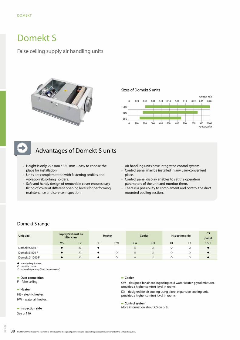
38
DOMEKT
KK-1
8-03
Domekt S
0 0,28 0,56 0,83 0,11 0,14 0,17 0,19 0,22 0,25 0,28
0 100 200 300 400 500 600 700 800 900 1000
1000
800
650
UAB KOMFOVENT reserves the right to introduce the changes of parameters and sizes in the process of improvement of the air handling units.
False ceiling supply air handling units
Duct connectionF – false ceiling
Heater
HE – electric heater.
HW – water air heater.
Inspection side
See p. 116.
Domekt S range
Cooler
CW – designed for air cooling using cold water (water-glycol mixture), provides a higher comfort level in rooms.
DX – designed for air cooling using direct expansion cooling unit, provides a higher comfort level in rooms.
Control system More information about C5 on p. 8.
� standard equipment� possible choice ordered separately (duct heater/cooler)
Air flow, m³/h
Air flow, m³/s
Sizes of Domekt S units
Unit size Supply/exhaust air filter class Heater Cooler Inspection side
C5
panel
M5 F7 HE HW CW DX R1 L1 C5.1
Domekt S 650 F � � � � � �
Domekt S 800 F � � � � � � �
Domekt S 1000 F � � � � � � �
Advantages of Domekt S units
• Height is only 297 mm / 350 mm – easy to choose the place for installation.
• Units are complemented with fastening profiles and vib ration absorbing holders.
• Safe and handy design of removable cover ensures easy fi xing of cover at different opening levels for perfor ming maintenance and service inspection.
• Air handling units have integrated control system.• Control panel may be installed in any user-convenient
place.• Control panel display enables to set the operation
parameters of the unit and monitor them.• There is a possibility to complement and control the duct
mounted cooling section.
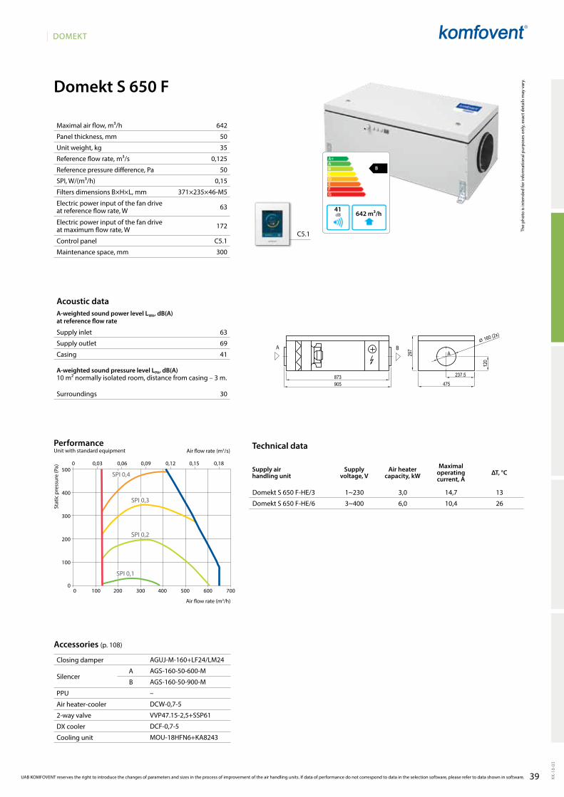
39
DOMEKT
KK-1
8-03
Domekt S 650 F
B
642 m³/h41
642
50
35
0,125
50
0,15
371×235×46-M5
63
172
C5.1
300
63
69
41
30
Domekt S 650 F-HE/3 1~230 3,0 14,7 13
Domekt S 650 F-HE/6 3~400 6,0 10,4 26
C5.1
AGUJ-M-160+LF24/LM24
AGS-160-50-600-M
AGS-160-50-900-M
–
DCW-0,7-5
VVP47.15-2,5+SSP61
DCF-0,7-5
MOU-18HFN6+KA8243
500
400
300
200
100
00 100 200 300 400 500 600 700
0 0,03 0,06 0,09 0,12 0,15 0,18
SPI 0,2
SPI 0,3
SPI 0,4
SPI 0,1
Domekt_S_650
AA B
237.5
120
475873905
297
⌀ 160 (2x)
Maximal air flow, m³/h
Panel thickness, mm
Unit weight, kg
Reference flow rate, m³/s
Reference pressure difference, Pa
SPI, W/(m³/h)
Filters dimensions B×H×L, mm
Electric power input of the fan drive at reference flow rate, W
Electric power input of the fan drive at maximum flow rate, W
Control panel
Maintenance space, mm
The
phot
o is
inte
nded
for i
nfor
mat
iona
l pur
pose
s on
ly, e
xact
det
ails
may
var
y.
Acoustic dataA-weighted sound power level LwA, dB(A)at reference flow rate
Supply inlet
Supply outlet
Casing
A-weighted sound pressure level LPA, dB(A) 10 m² normally isolated room, distance from casing – 3 m.
Surroundings
Stat
ic p
ress
ure
(Pa)
Air flow rate (m3/s)
Air flow rate (m3/h)
PerformanceUnit with standard equipment
Closing damper
SilencerA
B
PPU
Air heater-cooler
2-way valve
DX cooler
Cooling unit
Accessories (p. 108)
Technical data
Supply air handling unit
Supply voltage, V
Air heater capacity, kW
Maximal operating current, A
ΔT, °C
UAB KOMFOVENT reserves the right to introduce the changes of parameters and sizes in the process of improvement of the air handling units. If data of performance do not correspond to data in the selection software, please refer to data shown in software.
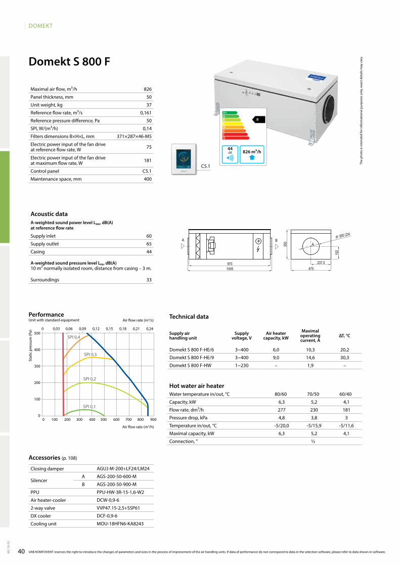
40
DOMEKT
KK-1
8-03
Domekt S 800 F
60
65
44
33
Domekt S 800 F-HE/6 3~400 6,0 10,3 20,2
Domekt S 800 F-HE/9 3~400 9,0 14,6 30,3
Domekt S 800 F-HW 1~230 – 1,9 –
826
50
37
0,161
50
0,14
371×287×46-M5
75
181
C5.1
400
B
826 m³/h44
C5.1
AGUJ-M-200+LF24/LM24
AGS-200-50-600-M
AGS-200-50-900-M
PPU-HW-3R-15-1,6-W2
DCW-0,9-6
VVP47.15-2,5+SSP61
DCF-0,9-6
MOU-18HFN6-KA8243
500
400
300
200
100
0
0 0,03 0,06 0,09 0,12 0,15 0,18 0,21 0,24
0 100 200 300 400 500 600 700 800 900
SPI 0,1
SPI 0,2
SPI 0,3
SPI 0,4
Domekt_S_800
350 A
A B
237.5
152
475973
1005
⌀ 200 (2x)
Maximal air flow, m³/h
Panel thickness, mm
Unit weight, kg
Reference flow rate, m³/s
Reference pressure difference, Pa
SPI, W/(m³/h)
Filters dimensions B×H×L, mm
Electric power input of the fan drive at reference flow rate, W
Electric power input of the fan drive at maximum flow rate, W
Control panel
Maintenance space, mm
The
phot
o is
inte
nded
for i
nfor
mat
iona
l pur
pose
s on
ly, e
xact
det
ails
may
var
y.
Acoustic dataA-weighted sound power level LwA, dB(A)at reference flow rate
Supply inlet
Supply outlet
Casing
A-weighted sound pressure level LPA, dB(A) 10 m² normally isolated room, distance from casing – 3 m.
Surroundings
Stat
ic p
ress
ure
(Pa)
Air flow rate (m3/s)
Air flow rate (m3/h)
PerformanceUnit with standard equipment
Closing damper
SilencerA
B
PPU
Air heater-cooler
2-way valve
DX cooler
Cooling unit
Accessories (p. 108)
Hot water air heaterWater temperature in/out, °C 80/60 70/50 60/40
Capacity, kW
Flow rate, dm³/h
Pressure drop, kPa
Temperature in/out, °C
Maximal capacity, kW
Connection, ”
Technical data
Supply air handling unit
Supply voltage, V
Air heater capacity, kw
Maximal operating current, A
ΔT, °C
UAB KOMFOVENT reserves the right to introduce the changes of parameters and sizes in the process of improvement of the air handling units. If data of performance do not correspond to data in the selection software, please refer to data shown in software.
6,3 5,2 4,1
277 230 181
4,8 3,8 3
-5/20,0 -5/15,9 -5/11,6
6,3 5,2 4,1
½
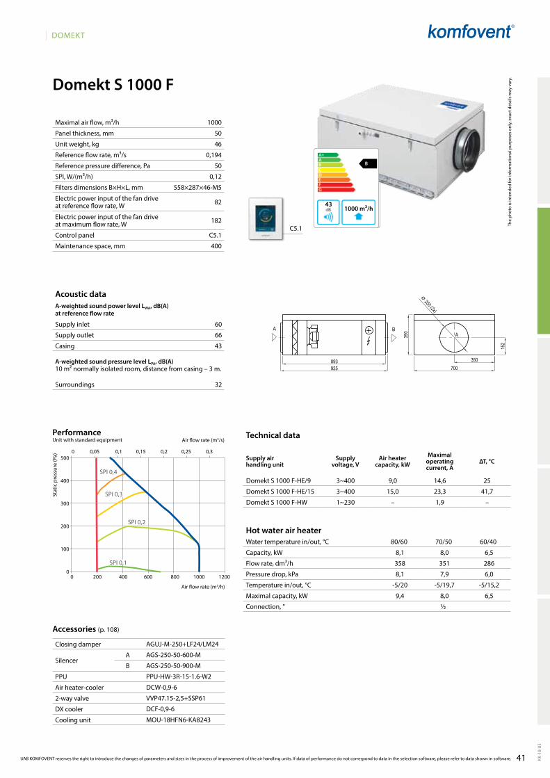
41
DOMEKT
KK-1
8-03
1000
50
46
0,194
50
0,12
558×287×46-M5
82
182
C5.1
400
B
642 m³/h41
C5.1
AGUJ-M-250+LF24/LM24
AGS-250-50-600-M
AGS-250-50-900-M
PPU-HW-3R-15-1.6-W2
DCW-0,9-6
VVP47.15-2,5+SSP61
DCF-0,9-6
MOU-18HFN6-KA8243
Domekt S 1000 F
60
66
43
32
1000 m³/h43
B
Domekt S 1000 F-HE/9 3~400 9,0 14,6 25
Domekt S 1000 F-HE/15 3~400 15,0 23,3 41,7
Domekt S 1000 F-HW 1~230 – 1,9 –
0 200 400 600 800 1000 1200
0 0,05 0,1 0,15 0,2 0,25 0,3500
400
300
200
100
0
SPI 0,2
SPI 0,3
SPI 0,4
SPI 0,1
Domekt_S_1000
AA B
350
152
700893925
350
⌀ 250 (2x)
Maximal air flow, m³/h
Panel thickness, mm
Unit weight, kg
Reference flow rate, m³/s
Reference pressure difference, Pa
SPI, W/(m³/h)
Filters dimensions B×H×L, mm
Electric power input of the fan drive at reference flow rate, W
Electric power input of the fan drive at maximum flow rate, W
Control panel
Maintenance space, mm
The
phot
o is
inte
nded
for i
nfor
mat
iona
l pur
pose
s on
ly, e
xact
det
ails
may
var
y.
Acoustic dataA-weighted sound power level LwA, dB(A)at reference flow rate
Supply inlet
Supply outlet
Casing
A-weighted sound pressure level LPA, dB(A) 10 m² normally isolated room, distance from casing – 3 m.
Surroundings
Stat
ic p
ress
ure
(Pa)
Air flow rate (m3/s)
Air flow rate (m3/h)
PerformanceUnit with standard equipment
Closing damper
SilencerA
B
PPU
Air heater-cooler
2-way valve
DX cooler
Cooling unit
Accessories (p. 108)
Hot water air heaterWater temperature in/out, °C 80/60 70/50 60/40
Capacity, kW
Flow rate, dm³/h
Pressure drop, kPa
Temperature in/out, °C
Maximal capacity, kW
Connection, ”
Technical data
Supply air handling unit
Supply voltage, V
Air heater capacity, kW
Maximal operating current, A
ΔT, °C
UAB KOMFOVENT reserves the right to introduce the changes of parameters and sizes in the process of improvement of the air handling units. If data of performance do not correspond to data in the selection software, please refer to data shown in software.
8,1 8,0 6,5
358 351 286
8,1 7,9 6,0
-5/20 -5/19,7 -5/15,2
9,4 8,0 6,5
½
42
VERSOCommercial ventilation units
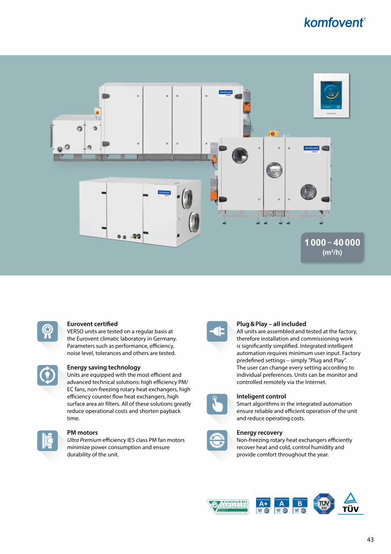
AHU N˚: 07.09.356Range: VERSO
43
1 000 – 40 000 (m3/h)
Eurovent certifiedVERSO units are tested on a regular basis at the Eurovent climatic laboratory in Germany. Parameters such as performance, efficiency, noise level, tolerances and others are tested.
Energy saving technologyUnits are equipped with the most efficient and advanced technical solutions: high efficiency PM/EC fans, non-freezing rotary heat exchangers, high efficiency counter flow heat exchangers, high surface area air filters. All of these solutions greatly reduce operational costs and shorten payback time.
PM motorsUltra Premium efficiency IE5 class PM fan motors minimize power consumption and ensure durability of the unit.
Plug & Play – all includedAll units are assembled and tested at the factory, therefore installation and commissioning work is significantly simplified. Integrated intelligent automation requires minimum user input. Factory predefined settings – simply "Plug and Play". The user can change every setting according to individual preferences. Units can be monitor and controlled remotely via the Internet.
Inteligent controlSmart algorithms in the integrated automation ensure reliable and efficient operation of the unit and reduce operating costs.
Energy recoveryNon-freezing rotary heat exchangers efficiently recover heat and cold, control humidity and provide comfort throughout the year.
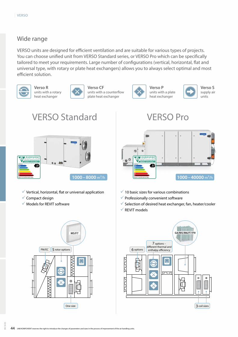
44KK-1
8-03
VERSO
VERSO Pro
ENERGY EFFICIENCY
A+ A+2016
07.09.356
Report to performance data
ABCDE
VERSO Standard
ENERGY EFFICIENCY
A+ A+2016
07.09.356
Report to performance data
ABCDE
1000 – 8000 m³/h 1000 – 40000 m³/h
M5/F7 G4/M5/M6/F7/F9
UAB KOMFOVENT reserves the right to introduce the changes of parameters and sizes in the process of improvement of the air handling units.
VERSO units are designed for efficient ventilation and are suitable for various types of projects. You can choose unified unit from VERSO Standard series, or VERSO Pro which can be specifically tailored to meet your requirements. Large number of configurations (vertical, horizontal, flat and universal type, with rotary or plate heat exchangers) allows you to always select optimal and most efficient solution.
Wide range
Verso CF units with a counterflow plate heat exchanger
Verso R units with a ro ta ry he at ex chan ger
Verso S sup ply air units
Verso P units with a pla te he at ex chan ger
10 basic sizes for various combinations Professionally convenient software Selection of desired heat exchanger, fan, heater/cooler REVIT models
Vertical, horizontal, flat or universal application Compact design Models for REVIT software
One size
PM/EC 5 rotor options
3 coil sizes
6 options
7 options – different thermal and
enthalpy efficiency
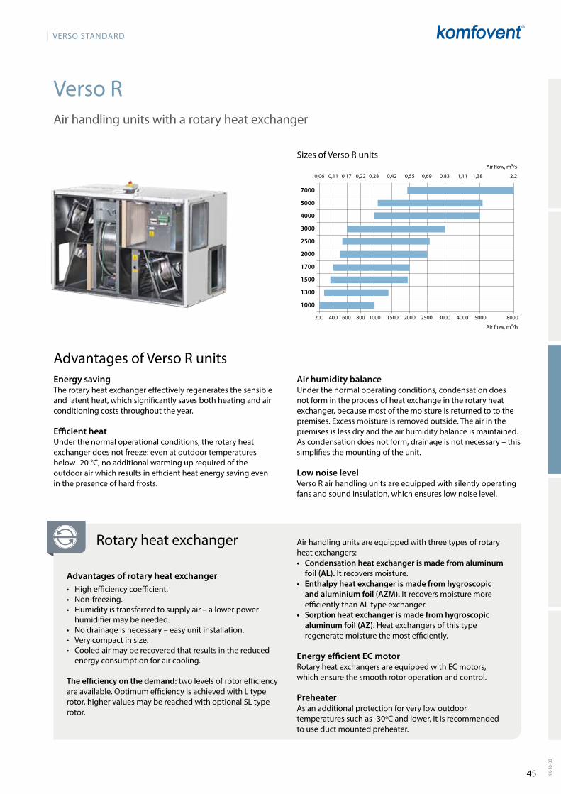
45
VERSO StandaRd
KK-1
8-03
Verso R
200 400 600 800 1000 1500 2000 2500 3000 4000 5000 8000
0,06 0,11 0,17 0,22 0,28 0,42 0,55 0,69 0,83 1,11 1,38 2,2
7000
5000
4000
3000
2500
2000
1700
1500
1300
1000
Air handling units with a rotary heat exchanger
Sizes of Verso R units
Air flow, m³/h
Air flow, m³/s
Rotary heat exchanger
Advantages of rotary heat exchanger• Highefficiencycoefficient.• Non-freezing.• Humidityistransferredtosupplyair–alowerpower
humidifier may be needed.• Nodrainageisnecessary–easyunitinstallation.• Verycompactinsize.• Cooledairmayberecoveredthatresultsinthereduced
energy consumption for air cooling.
The efficiency on the demand: two levels of rotor efficiency are available. Optimum efficiency is achieved with L type rotor, higher values may be reached with optional SL type rotor.
Air handling units are equipped with three types of rotary heat exchangers:• Condensation heat exchanger is made from aluminum
foil (AL). It recovers moisture.• Enthalpy heat exchanger is made from hygroscopic
and aluminium foil (AZM). It recovers moisture more efficiently than AL type exchanger.
• Sorption heat exchanger is made from hygroscopic aluminum foil (AZ). Heatexchangersofthistyperegenerate moisture the most efficiently.
Energy efficient EC motorRotary heat exchangers are equipped with EC motors, which ensure the smooth rotor ope ration and control.
PreheaterAs an additional protection for very low outdoor temperatures such as -30oC and lower, it is recommended to use duct mounted preheater.
Energy saving The rotary heat exchanger effectively regenerates the sensible and latent heat, which significantly saves both heating and air conditioning costs throughout the year.
Efficient heat Under the normal operational conditions, the rotary heat exchanger does not freeze: even at outdoor temperatures below -20 °C, no additional warming up required of the outdoor air which results in efficient heat energy saving even in the presence of hard frosts.
Advantages of Verso R unitsAir humidity balance Under the normal operating conditions, condensation does not form in the process of heat exchange in the rotary heat exchanger, because most of the moisture is returned to to the premises. Excess moisture is removed outside. The air in the premises is less dry and the air humidity balance is maintained. As condensation does not form, drainage is not necessary – this simplifies the mounting of the unit.
Low noise levelVerso R air handling units are equipped with silently ope rating fans and sound insulation, which ensures low noise level.
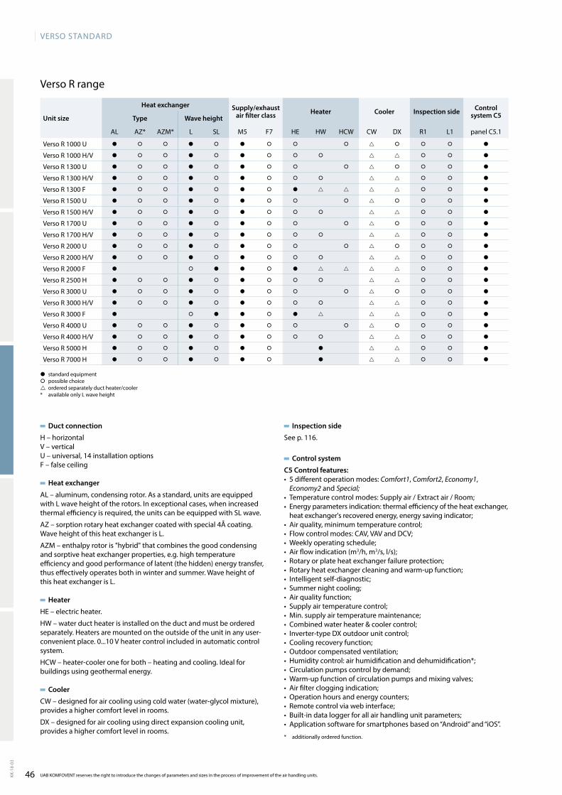
46
VERSO StandaRd
KK-1
8-03
UAB KOMFOVENT reserves the right to introduce the changes of parameters and sizes in the process of improvement of the air handling units.
Verso R range
Duct connection
H–horizontalV – verticalU – universal, 14 installation optionsF – false ceiling
Heat exchanger
AL – aluminum, condensing rotor. As a standard, units are equipped with L wave height of the rotors. In exceptional cases, when increased thermal efficiency is required, the units can be equipped with SL wave.
AZ – sorption rotary heat exchanger coated with special 4Å coating. Wave height of this heat exchanger is L.
AZM – enthalpy rotor is "hybrid" that combines the good condensing and sorptive heat exchanger properties, e.g. high temperature efficiency and good performance of latent (the hidden) energy transfer, thus effectively operates both in winter and summer. Wave height of this heat exchanger is L.
Heater
HE–electricheater.
HW–waterductheaterisinstalledontheductandmustbeorderedseparately.Heatersaremountedontheoutsideoftheunitinanyuser-convenient place. 0...10 V heater control included in automatic control system.
HCW–heater-cooleroneforboth–heatingandcooling.Idealforbuildings using geothermal energy.
Cooler
CW – designed for air cooling using cold water (water-glycol mixture), provides a higher comfort level in rooms.
DX – designed for air cooling using direct expansion cooling unit, provides a higher comfort level in rooms.
� standard equipment� possible choice ordered separately duct heater/cooler* available only L wave height
Inspection side
See p. 116.
Control system
C5 Control features:• 5differentoperationmodes:Comfort1, Comfort2, Economy1,
Economy2 and Special;• Temperaturecontrolmodes:Supplyair/Extractair/Room;• Energyparametersindication:thermalefficiencyoftheheatexchanger,heatexchanger'srecoveredenergy,energysavingindicator;
• Airquality,minimumtemperaturecontrol;• Flowcontrolmodes:CAV,VAVandDCV;• Weeklyoperatingschedule;• Airflowindication(m3/h, m3/s,l/s);• Rotaryorplateheatexchangerfailureprotection;• Rotaryheatexchangercleaningandwarm-upfunction;• Intelligentself-diagnostic;• Summernightcooling;• Airqualityfunction;• Supplyairtemperaturecontrol;• Min.supplyairtemperaturemaintenance;• Combinedwaterheater&coolercontrol;• Inverter-typeDXoutdoorunitcontrol;• Coolingrecoveryfunction;• Outdoorcompensatedventilation;• Humiditycontrol:airhumidificationanddehumidification*;• Circulationpumpscontrolbydemand;• Warm-upfunctionofcirculationpumpsandmixingvalves;• Airfiltercloggingindication;• Operationhoursandenergycounters;• Remotecontrolviawebinterface;• Built-indataloggerforallairhandlingunitparameters;• Applicationsoftwareforsmartphonesbasedon“Android”and“iOS”.
* additionally ordered function.
Unit size
Heat exchanger Supply/exhaust air filter class Heater Cooler Inspection side Control
system C5Type Wave height
AL AZ* AZM* L SL M5 F7 HE HW HCW CW DX R1 L1 panel C5.1
Verso R 1000 U � � � � � � � � � � � � �
VersoR1000H/V � � � � � � � � � � � �
Verso R 1300 U � � � � � � � � � � � � �
VersoR1300H/V � � � � � � � � � � � �
Verso R 1300 F � � � � � � � � � � �
Verso R 1500 U � � � � � � � � � � � � �
VersoR1500H/V � � � � � � � � � � � �
Verso R 1700 U � � � � � � � � � � � � �
VersoR1700H/V � � � � � � � � � � � �
Verso R 2000 U � � � � � � � � � � � � �
VersoR2000H/V � � � � � � � � � � � �
Verso R 2000 F � � � � � � � � �
VersoR2500H � � � � � � � � � � � �
Verso R 3000 U � � � � � � � � � � � � �
VersoR3000H/V � � � � � � � � � � � �
Verso R 3000 F � � � � � � � � �
Verso R 4000 U � � � � � � � � � � � � �
VersoR4000H/V � � � � � � � � � � � �
VersoR5000H � � � � � � � � � � �
VersoR7000H � � � � � � � � � � �
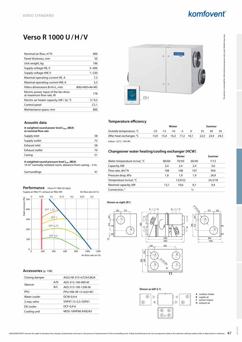
47
VERSO StandaRd
KK-1
8-03
Verso R 1000 U / H / V
C
DB
A C
C
A
A
B
B
D
D
AGUJ-M-315+LF24/LM24
AGS-315-100-900-M
AGS-315-100-1200-M
PPU-HW-3R-15-0,63-W1
DCW-0,9-6
VVP47.15-2,5+SSP61
DCF-0,9-6
MOU-18HFN6-KA8243
58
72
58
70
51
41
500
400
300
200
100
00 200 400 600 800 1000 1200
0 0,05 0,1 0,15 0,2 0,25 0,3
SFP 0,5
SFP 1,25
SFP 1
SFP 0,75
13,9 15,4 16,3 17,2 18,1 22,5 23,4 24,3
2,4 2,4 2,4 5,6
108 108 107 954
1,8 1,9 1,9 24,9
13,9/22 24,3/18
13,1 10,6 8,1 9,4
½
900
50
196
3~400
1~230
7,3
3,3
800×400×46-M5
178
3 / 9,3
C5.1
800
C5.1
13551505
282
906
372282 372
247
412
905
247
412
906
398
250 855
253
980
100215
⌀ 315 (4x)
⌀ 315 (4x)
A
D
Verso_R_1000_R1
A
D
C
B
C
B
AD CB
C
B
A
D
The
phot
o is
inte
nded
for i
nfor
mat
iona
l pur
pose
s on
ly, e
xact
det
ails
may
var
y.
Acoustic dataA-weighted sound power level LwA, dB(A)at nominal flow rate
Supply inlet
Supply outlet
Exhaust inlet
Exhaust outlet
Casing
A-weighted sound pressure level LPA, dB(A) 10 m² normally isolated room, distance from casing – 3 m.
Surroundings
Changeover water heating/cooling exchanger (HCW)Winter Summer
Water temperature in/out, °C 80/60 70/50 60/40 7/12
Capacity, kW
Flow rate, dm³/h
Pressure drop, kPa
Temperature in/out, °C
Maximal capacity, kW
Connection, ”
Stat
ic p
ress
ure
(Pa)
Air flow rate (m3/h)
Accessories (p. 108)
Closing damper
SilencerA/D
B/C
PPU
Water cooler
2-way valve
DX cooler
Cooling unit
Temperature efficiencyWinter Summer
Outside temperature, °C -23 -15 -10 -5 0 25 30 35
After heat exchanger, °C
indoor +22°C, 10% RH
Nominal air flow, m³/h
Panel thickness, mm
Unit weight, kg
Supply voltage HE, V
Supply voltage HW, V
Maximal operating current HE, A
Maximal operating current HW, A
Filters dimensions B×H×L, mm
Electric power input of the fan drive at maximum flow rate, W
Electric air heater capacity, kW / ∆t, °C
Control panel
Maintenance space, mm
UAB KOMFOVENT reserves the right to introduce the changes of parameters and sizes in the process of improvement of the air handling units. If data of performance do not correspond to data in the selection software, please refer to data shown in software.
Air flow rate (m3/s)
PerformanceSupply air filter F7, exhaust air filter M5
A outdoor intakeB supply airC extract indoorD exhaust air
(VersoR1000UHdata)
Shown as right (R1)
Shown as left (L1)
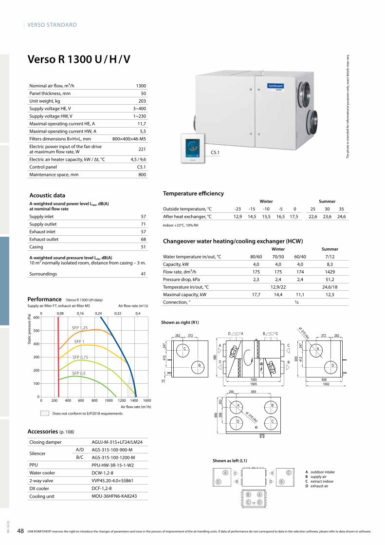
48
VERSO StandaRd
KK-1
8-03
C
DB
A C
C
A
A
B
B
D
D
12,9 14,5 15,5 16,5 17,5 22,6 23,6 24,6
4,0 4,0 4,0 8,3
175 175 174 1429
2,3 2,4 2,4 51,2
12,9/22 24,6/18
17,7 14,4 11,1 12,3
½
Verso R 1300 U / H / V
1300
50
203
3~400
1~230
11,7
5,5
800×400×46-M5
221
4,5 / 9,6
C5.1
800
57
71
57
68
51
41
AGUJ-M-315+LF24/LM24
AGS-315-100-900-M
AGS-315-100-1200-M
PPU-HW-3R-15-1-W2
DCW-1,2-8
VVP45.20-4.0+SSB61
DCF-1,2-8
MOU-36HFN6-KA8243
C5.1
600
500
400
300
200
100
00 200 400 600 800 1000 1200 1400 1600
0 0,08 0,16 0,24 0,32 0,4
SFP 0,5
SFP 1,25
SFP 1
SFP 0,75
13551505
282
906
372282 372
247
412
905
247
412
906
398
250 855
253
980
100215
⌀ 315 (4x)
⌀ 315 (4x)
A
D
Verso_R_1000_R1
A
D
C
B
C
B
AD CB
C
B
A
D
The
phot
o is
inte
nded
for i
nfor
mat
iona
l pur
pose
s on
ly, e
xact
det
ails
may
var
y.
Acoustic dataA-weighted sound power level LwA, dB(A)at nominal flow rate
Supply inlet
Supply outlet
Exhaust inlet
Exhaust outlet
Casing
A-weighted sound pressure level LPA, dB(A) 10 m² normally isolated room, distance from casing – 3 m.
Surroundings
Changeover water heating/cooling exchanger (HCw)winter Summer
Water temperature in/out, °C 80/60 70/50 60/40 7/12
Capacity, kW
Flow rate, dm³/h
Pressure drop, kPa
Temperature in/out, °C
Maximal capacity, kW
Connection, ”
Stat
ic p
ress
ure
(Pa)
Air flow rate (m3/h)
Accessories (p. 108)
Closing damper
SilencerA/D
B/C
PPU
Water cooler
2-way valve
DX cooler
Cooling unit
Temperature efficiencywinter Summer
Outside temperature, °C -23 -15 -10 -5 0 25 30 35
After heat exchanger, °C
indoor +22°C, 10% RH
Nominal air flow, m³/h
Panel thickness, mm
Unit weight, kg
Supply voltage HE, V
Supply voltage HW, V
Maximal operating current HE, A
Maximal operating current HW, A
Filters dimensions B×H×L, mm
Electric power input of the fan drive at maximum flow rate, W
Electric air heater capacity, kW / ∆t, °C
Control panel
Maintenance space, mm
UAB KOMFOVENT reserves the right to introduce the changes of parameters and sizes in the process of improvement of the air handling units. If data of performance do not correspond to data in the selection software, please refer to data shown in software.
Air flow rate (m3/s)
PerformanceSupply air filter F7, exhaust air filter M5
A outdoor intakeB supply airC extract indoorD exhaust air
(VersoR1300UHdata)
Does not conform to ErP2018 requirements
Shown as right (R1)
Shown as left (L1)
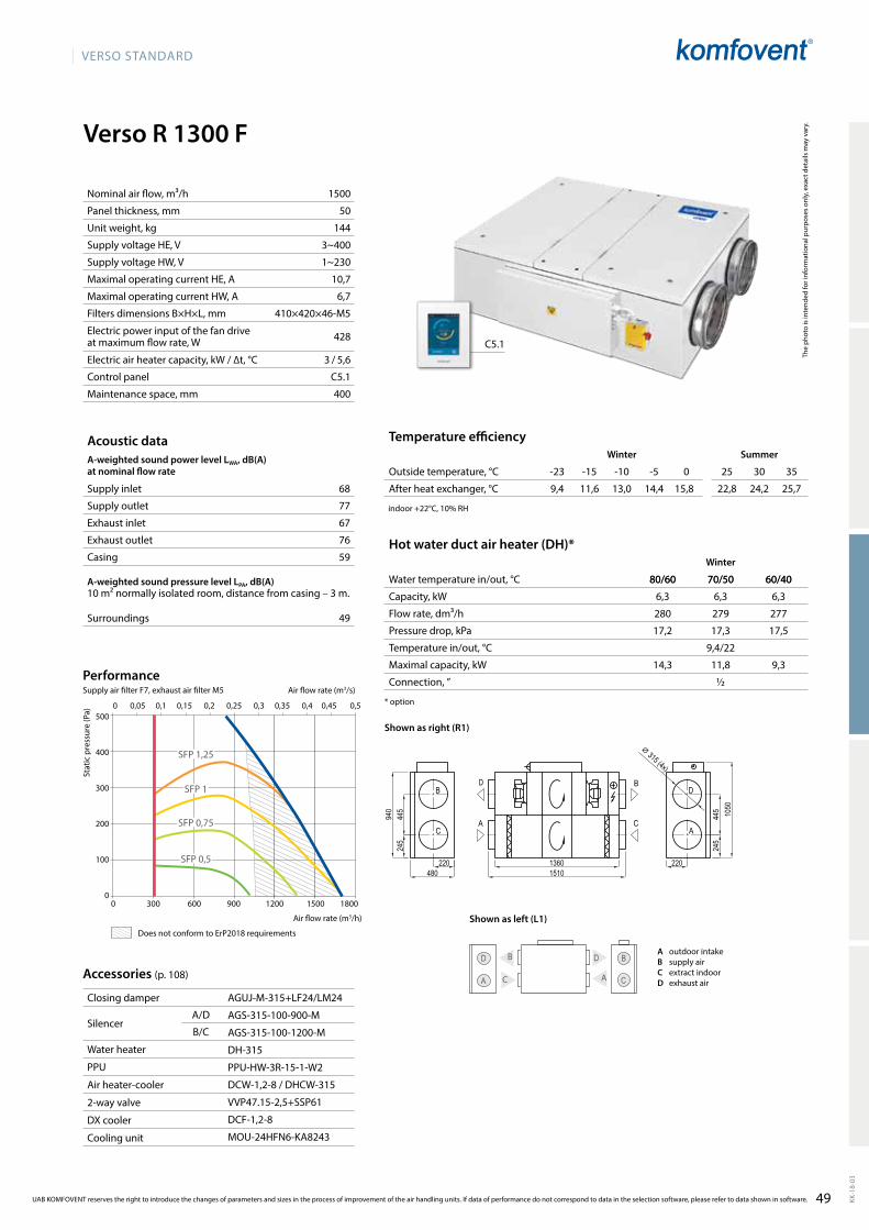
49
VERSO StandaRd
KK-1
8-03
1500
50
144
3~400
1~230
10,7
6,7
410×420×46-M5
428
3 / 5,6
C5.1
400
68
77
67
76
59
49
Verso R 1300 F
AGUJ-M-315+LF24/LM24
AGS-315-100-900-M
AGS-315-100-1200-M
DH-315
PPU-HW-3R-15-1-W2
DCW-1,2-8/DHCW-315
VVP47.15-2,5+SSP61
DCF-1,2-8
MOU-24HFN6-KA8243
C5.1
9,4 11,6 13,0 14,4 15,8 22,8 24,2 25,7
80/60 70/50 60/40
6,3 6,3 6,3
280 279 277
17,2 17,3 17,5
9,4/22
14,3 11,8 9,3
½
SFP 1,25
SFP 0,5
SFP 1
SFP 0,75
500
400
300
200
100
00 300 600 900 1200 1500 1800
0 0,05 0,1 0,15 0,2 0,25 0,3 0,35 0,4 0,45 0,5
B
C A
D B
AC
D
Verso_R_1300_R1
D BB D
C AA C
13601510
1050
220480
245
445
940
⌀ 315 (4x)
245
445
220
The
phot
o is
inte
nded
for i
nfor
mat
iona
l pur
pose
s on
ly, e
xact
det
ails
may
var
y.
Acoustic dataA-weighted sound power level LwA, dB(A)at nominal flow rate
Supply inlet
Supply outlet
Exhaust inlet
Exhaust outlet
Casing
A-weighted sound pressure level LPA, dB(A) 10 m² normally isolated room, distance from casing – 3 m.
Surroundings
Nominal air flow, m³/h
Panel thickness, mm
Unit weight, kg
Supply voltage HE, V
Supply voltage HW, V
Maximal operating current HE, A
Maximal operating current HW, A
Filters dimensions B×H×L, mm
Electric power input of the fan drive at maximum flow rate, W
Electric air heater capacity, kW / ∆t, °C
Control panel
Maintenance space, mm
Stat
ic p
ress
ure
(Pa)
Air flow rate (m3/h)
Accessories (p. 108)
Closing damper
SilencerA/D
B/C
Water heater
PPU
Air heater-cooler
2-way valve
DX cooler
Cooling unit
Temperature efficiencyWinter Summer
Outside temperature, °C -23 -15 -10 -5 0 25 30 35
After heat exchanger, °C
indoor +22°C, 10% RH
Hot water duct air heater (DH)*Winter
Water temperature in/out, °C 80/60 70/50 60/40
Capacity, kW
Flow rate, dm³/h
Pressure drop, kPa
Temperature in/out, °C
Maximal capacity, kW
Connection, ”
* option
UAB KOMFOVENT reserves the right to introduce the changes of parameters and sizes in the process of improvement of the air handling units. If data of performance do not correspond to data in the selection software, please refer to data shown in software.
Air flow rate (m3/s)
PerformanceSupply air filter F7, exhaust air filter M5
Shown as right (R1)
A outdoor intakeB supply airC extract indoorD exhaust air
Shown as left (L1)Does not conform to ErP2018 requirements
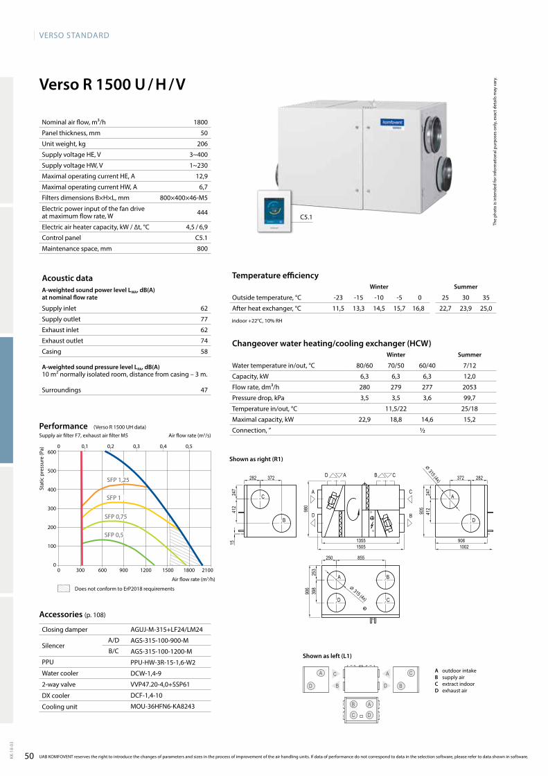
50
VERSO StandaRd
KK-1
8-03
62
77
62
74
58
47
Verso R 1500 U / H / V
AGUJ-M-315+LF24/LM24
AGS-315-100-900-M
AGS-315-100-1200-M
PPU-HW-3R-15-1,6-W2
DCW-1,4-9
VVP47.20-4,0+SSP61
DCF-1,4-10
MOU-36HFN6-KA8243
C5.1
600
500
400
300
200
100
00 300 600 900 1200 1500 1800 2100
0 0,1 0,2 0,3 0,4 0,5
SFP 0,5
SFP 1,25
SFP 1
SFP 0,75
11,5 13,3 14,5 15,7 16,8 22,7 23,9 25,0
6,3 6,3 6,3 12,0
280 279 277 2053
3,5 3,5 3,6 99,7
11,5/22 25/18
22,9 18,8 14,6 15,2
½
1800
50
206
3~400
1~230
12,9
6,7
800×400×46-M5
444
4,5 / 6,9
C5.1
800
C
DB
A C
C
A
A
B
B
D
D
13551505
282
906
372282 372
247
412
905
247
412
906
398
250 855
253
980
100215
⌀ 315 (4x)
⌀ 315 (4x)
A
D
Verso_R_1000_R1
A
D
C
B
C
B
AD CB
C
B
A
D
The
phot
o is
inte
nded
for i
nfor
mat
iona
l pur
pose
s on
ly, e
xact
det
ails
may
var
y.
Acoustic dataA-weighted sound power level LwA, dB(A)at nominal flow rate
Supply inlet
Supply outlet
Exhaust inlet
Exhaust outlet
Casing
A-weighted sound pressure level LPA, dB(A) 10 m² normally isolated room, distance from casing – 3 m.
Surroundings
Changeover water heating/cooling exchanger (HCw)winter Summer
Water temperature in/out, °C 80/60 70/50 60/40 7/12
Capacity, kW
Flow rate, dm³/h
Pressure drop, kPa
Temperature in/out, °C
Maximal capacity, kW
Connection, ”
Stat
ic p
ress
ure
(Pa)
Air flow rate (m3/h)
Accessories (p. 108)
Closing damper
SilencerA/D
B/C
PPU
Water cooler
2-way valve
DX cooler
Cooling unit
Temperature efficiencywinter Summer
Outside temperature, °C -23 -15 -10 -5 0 25 30 35
After heat exchanger, °C
indoor +22°C, 10% RH
Nominal air flow, m³/h
Panel thickness, mm
Unit weight, kg
Supply voltage HE, V
Supply voltage HW, V
Maximal operating current HE, A
Maximal operating current HW, A
Filters dimensions B×H×L, mm
Electric power input of the fan drive at maximum flow rate, W
Electric air heater capacity, kW / ∆t, °C
Control panel
Maintenance space, mm
UAB KOMFOVENT reserves the right to introduce the changes of parameters and sizes in the process of improvement of the air handling units. If data of performance do not correspond to data in the selection software, please refer to data shown in software.
Air flow rate (m3/s)
PerformanceSupply air filter F7, exhaust air filter M5
Does not conform to ErP2018 requirements
(VersoR1500UHdata)
Shown as right (R1)
A outdoor intakeB supply airC extract indoorD exhaust air
Shown as left (L1)
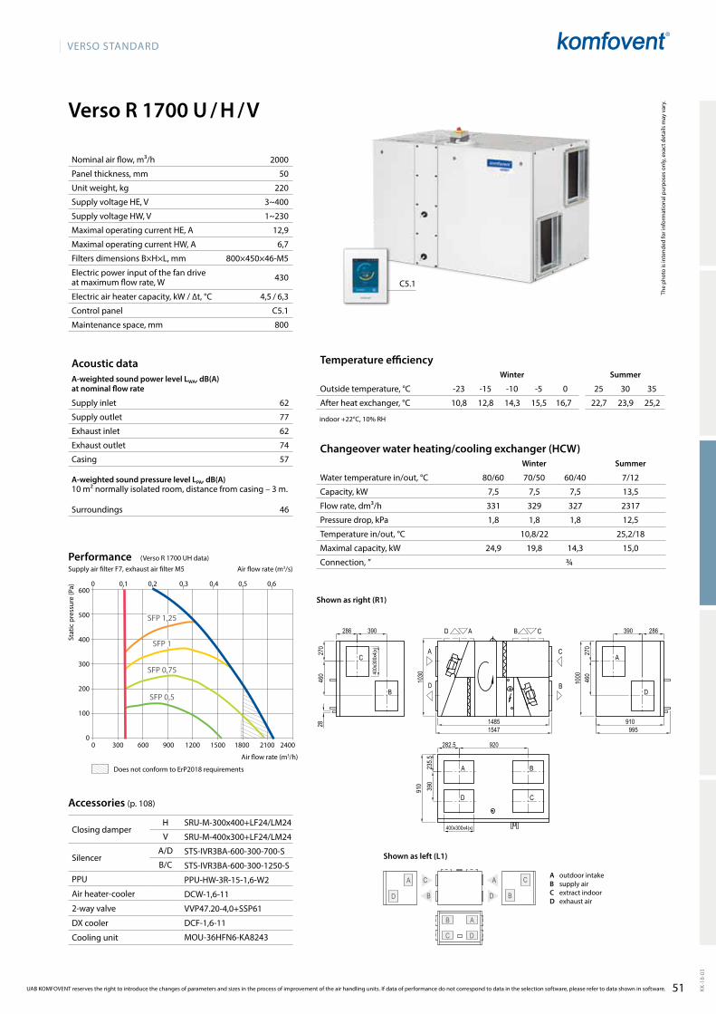
VERSO StandaRd
51 KK-1
8-03
Verso R 1700 U / H / V
62
77
62
74
57
46
C
DB
A
C
A C
D B
D
AB
SRU-M-300x400+LF24/LM24
SRU-M-400x300+LF24/LM24
STS-IVR3BA-600-300-700-S
STS-IVR3BA-600-300-1250-S
PPU-HW-3R-15-1,6-W2
DCW-1,6-11
VVP47.20-4,0+SSP61
DCF-1,6-11
MOU-36HFN6-KA8243
C5.1
10,8 12,8 14,3 15,5 16,7 22,7 23,9 25,2
7,5 7,5 7,5 13,5
331 329 327 2317
1,8 1,8 1,8 12,5
10,8/22 25,2/18
24,9 19,8 14,3 15,0
¾
600
500
400
300
200
100
0
0 0,1 0,2 0,3 0,4 0,5 0,6
0 300 600 900 1200 1500 1800 2100 2400
2000
50
220
3~400
1~230
12,9
6,7
800×450×46-M5
430
4,5 / 6,3
C5.1
800
SFP 1,25
SFP 0,5
SFP 1
SFP 0,75
Verso_R_1700_R1
A
D
C
B
AD CB
C
B
A
D
A B
D C
14851547
910
1000
910
1030
995
28
286 390
270
460
390
270
46040
0x30
0x4(
x)
286
282.5 920
235.5
390
400x300x4(x)
Accessories (p. 108)
Closing damperH
V
SilencerA/D
B/C
PPU
Air heater-cooler
2-way valve
DX cooler
Cooling unit
UAB KOMFOVENT reserves the right to introduce the changes of parameters and sizes in the process of improvement of the air handling units. If data of performance do not correspond to data in the selection software, please refer to data shown in software.
The
phot
o is
inte
nded
for i
nfor
mat
iona
l pur
pose
s on
ly, e
xact
det
ails
may
var
y.
Acoustic dataA-weighted sound power level LwA, dB(A)at nominal flow rate
Supply inlet
Supply outlet
Exhaust inlet
Exhaust outlet
Casing
A-weighted sound pressure level LPA, dB(A) 10 m² normally isolated room, distance from casing – 3 m.
Surroundings
Changeover water heating/cooling exchanger (HCW)Winter Summer
Water temperature in/out, °C 80/60 70/50 60/40 7/12
Capacity, kW
Flow rate, dm³/h
Pressure drop, kPa
Temperature in/out, °C
Maximal capacity, kW
Connection, ”
Stat
ic p
ress
ure
(Pa)
Air flow rate (m3/h)
Temperature efficiencyWinter Summer
Outside temperature, °C -23 -15 -10 -5 0 25 30 35
After heat exchanger, °C
indoor +22°C, 10% RH
Nominal air flow, m³/h
Panel thickness, mm
Unit weight, kg
Supply voltage HE, V
Supply voltage HW, V
Maximal operating current HE, A
Maximal operating current HW, A
Filters dimensions B×H×L, mm
Electric power input of the fan drive at maximum flow rate, W
Electric air heater capacity, kW / ∆t, °C
Control panel
Maintenance space, mm
Air flow rate (m3/s)
PerformanceSupply air filter F7, exhaust air filter M5
A outdoor intakeB supply airC extract indoorD exhaust air
Shown as left (L1)
Shown as right (R1)
Does not conform to ErP2018 requirements
(VersoR1700UHdata)
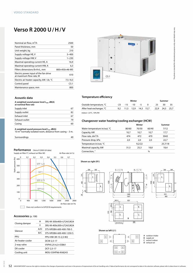
VERSO StandaRd
52KK-1
8-03
C
DB
A
C
A C
D B
D
AB
Verso R 2000 U / H / V
67
82
67
79
60
49
SRU-M-300x400+LF24/LM24
SRU-M-400x300+LF24/LM24
STS-IVR3BA-600-400-700-S
STS-IVR3BA-600-400-1250-S
PPU-HW-3R-15-2,5-W2
DCW-2,5-17
VVP45.25-6,3+SSB61
DCF-2,5-17
MOU-55HFN6-KA8243
C5.1
9,2 11,5 12,9 14,3 15,7 22,9 24,3 25,7
10,7 10,7 10,7 17,7
474 472 470 3043
2,0 2,0 2,0 22,7
9,2/22 25,7/18
31,5 25,3 18,8 18,4
¾
600
500
400
300
200
100
00 400 800 1200 1600 2000 2400 2800
0 0,1 0,2 0,3 0,4 0,5 0,6 0,7
2500
50
210
3~400
1~230
16,9
6,3
800×450×46-M5
610
7,5 / 8,3
C5.1
800
SFP 1,25
SFP 0,5
SFP 1
SFP 0,75
Verso_R_1700_R1
A
D
C
B
AD CB
C
B
A
D
A B
D C
14851547
910
1000
910
1030
995
28
286 390
270
460
390
270
46040
0x30
0x4(
x)
286
282.5 920
235.5
390
400x300x4(x)
Accessories (p. 108)
Closing damperH
V
SilencerA/D
B/C
PPU
Air heater-cooler
2-way valve
DX cooler
Cooling unit
UAB KOMFOVENT reserves the right to introduce the changes of parameters and sizes in the process of improvement of the air handling units. If data of performance do not correspond to data in the selection software, please refer to data shown in software.
The
phot
o is
inte
nded
for i
nfor
mat
iona
l pur
pose
s on
ly, e
xact
det
ails
may
var
y.
Acoustic dataA-weighted sound power level LwA, dB(A)at nominal flow rate
Supply inlet
Supply outlet
Exhaust inlet
Exhaust outlet
Casing
A-weighted sound pressure level LPA, dB(A) 10 m² normally isolated room, distance from casing – 3 m.
Surroundings
Changeover water heating/cooling exchanger (HCw)winter Summer
Water temperature in/out, °C 80/60 70/50 60/40 7/12
Capacity, kW
Flow rate, dm³/h
Pressure drop, kPa
Temperature in/out, °C
Maximal capacity, kW
Connection, ”
Stat
ic p
ress
ure
(Pa)
Air flow rate (m3/h)
Temperature efficiencywinter Summer
Outside temperature, °C -23 -15 -10 -5 0 25 30 35
After heat exchanger, °C
indoor +22°C, 10% RH
Nominal air flow, m³/h
Panel thickness, mm
Unit weight, kg
Supply voltage HE, V
Supply voltage HW, V
Maximal operating current HE, A
Maximal operating current HW, A
Filters dimensions B×H×L, mm
Electric power input of the fan drive at maximum flow rate, W
Electric air heater capacity, kW / ∆t, °C
Control panel
Maintenance space, mm
Air flow rate (m3/s)
PerformanceSupply air filter F7, exhaust air filter M5
A outdoor intakeB supply airC extract indoorD exhaust air
Shown as left (L1)
Shown as right (R1)
Does not conform to ErP2018 requirements
(VersoR2000UHdata)
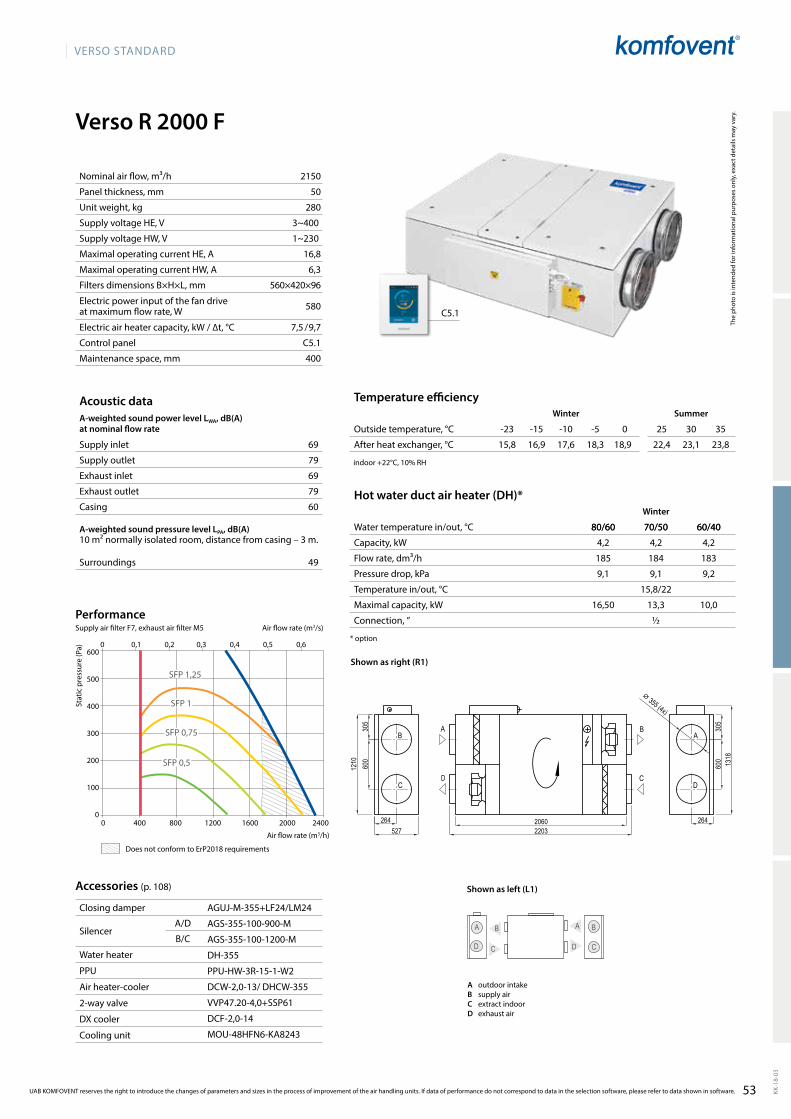
53
VERSO STANDARD
KK-1
8-03
Verso R 2000 F
69
79
69
79
60
49
D
A B
C
B
D
A
C
AGUJ-M-355+LF24/LM24
AGS-355-100-900-M
AGS-355-100-1200-M
DH-355
PPU-HW-3R-15-1-W2
DCW-2,0-13/ DHCW-355
VVP47.20-4,0+SSP61
DCF-2,0-14
MOU-48HFN6-KA8243
C5.1
600
500
400
300
200
100
00 400 800 1200 1600 2000 2400
0 0,1 0,2 0,3 0,4 0,5 0,6
SFP 0,5
SFP 0,75
SFP 1
SFP 1,25
15,8 16,9 17,6 18,3 18,9 22,4 23,1 23,8
2150
50
280
3~400
1~230
16,8
6,3
560×420×96
580
7,5 / 9,7
C5.1
400
80/60 70/50 60/40
4,2 4,2 4,2
185 184 183
9,1 9,1 9,2
15,8/22
16,50 13,3 10,0
½
Verso_R_2000_R1
BA
CD
B
C
A
D
20602203527
1210 13
18
305
600
305
600
264 264
⌀ 355 (4x)
The
phot
o is
inte
nded
for i
nfor
mat
iona
l pur
pose
s on
ly, e
xact
det
ails
may
var
y.
Acoustic dataA-weighted sound power level LWA, dB(A)at nominal flow rate
Supply inlet
Supply outlet
Exhaust inlet
Exhaust outlet
Casing
A-weighted sound pressure level LPA, dB(A) 10 m² normally isolated room, distance from casing – 3 m.
Surroundings
Nominal air flow, m³/h
Panel thickness, mm
Unit weight, kg
Supply voltage HE, V
Supply voltage HW, V
Maximal operating current HE, A
Maximal operating current HW, A
Filters dimensions B×H×L, mm
Electric power input of the fan drive at maximum flow rate, W
Electric air heater capacity, kW / ∆t, °C
Control panel
Maintenance space, mm
Stat
ic p
ress
ure
(Pa)
Air flow rate (m3/h)
Accessories (p. 108)
Closing damper
SilencerA/D
B/C
Water heater
PPU
Air heater-cooler
2-way valve
DX cooler
Cooling unit
Temperature efficiencyWinter Summer
Outside temperature, °C -23 -15 -10 -5 0 25 30 35
After heat exchanger, °C
indoor +22°C, 10% RH
Hot water duct air heater (DH)*Winter
Water temperature in/out, °C 80/60 70/50 60/40
Capacity, kW
Flow rate, dm³/h
Pressure drop, kPa
Temperature in/out, °C
Maximal capacity, kW
Connection, ”
* option
UAB KOMFOVENT reserves the right to introduce the changes of parameters and sizes in the process of improvement of the air handling units. If data of performance do not correspond to data in the selection software, please refer to data shown in software.
Air flow rate (m3/s)
PerformanceSupply air filter F7, exhaust air filter M5
A outdoor intakeB supply airC extract indoorD exhaust air
Shown as right (R1)
Shown as left (L1)
Does not conform to ErP2018 requirements
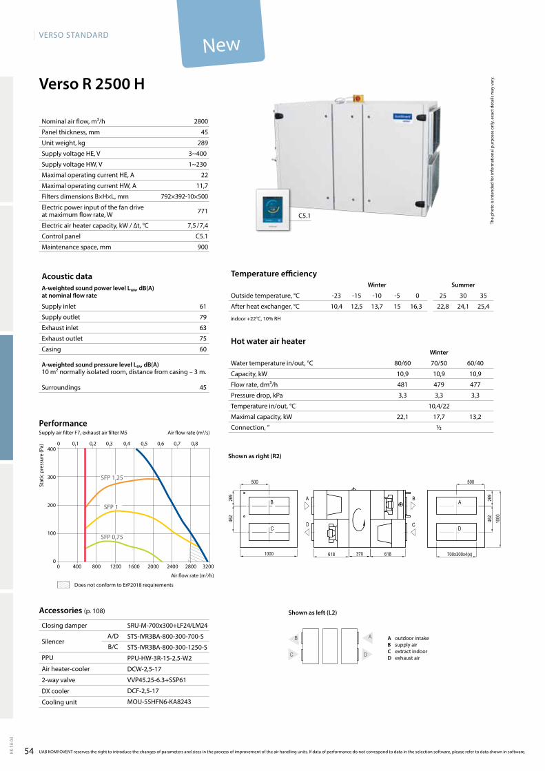
54
VERSO StandaRd
KK-1
8-03
Verso R 2500 H
61
79
63
75
60
45
SRU-M-700x300+LF24/LM24
STS-IVR3BA-800-300-700-S
STS-IVR3BA-800-300-1250-S
PPU-HW-3R-15-2,5-W2
DCW-2,5-17
VVP45.25-6.3+SSP61
DCF-2,5-17
MOU-55HFN6-KA8243
2800
45
289
3~400
1~230
22
11,7
792×392-10×500
771
7,5 / 7,4
C5.1
900
400
300
200
100
00 400 800 1200 1600 2000 2400 2800 3200
0 0,1 0,2 0,3 0,4 0,5 0,6 0,7 0,8
SFP 1,25
SFP 1
SFP 0,75
C5.1
B A
C D
10,4 12,5 13,7 15 16,3 22,8 24,1 25,4
10,9 10,9 10,9
481 479 477
3,3 3,3 3,3
10,4/22
22,1 17,7 13,2
½
Verso_R_2500_R2
A
D
B
C
A
D C
B
1000 618 370 618
1000
500
269
462
269
462
500
700x300x4(x)
The
phot
o is
inte
nded
for i
nfor
mat
iona
l pur
pose
s on
ly, e
xact
det
ails
may
var
y.
Acoustic dataA-weighted sound power level LwA, dB(A)at nominal flow rate
Supply inlet
Supply outlet
Exhaust inlet
Exhaust outlet
Casing
A-weighted sound pressure level LPA, dB(A) 10 m² normally isolated room, distance from casing – 3 m.
Surroundings
Nominal air flow, m³/h
Panel thickness, mm
Unit weight, kg
Supply voltage HE, V
Supply voltage HW, V
Maximal operating current HE, A
Maximal operating current HW, A
Filters dimensions B×H×L, mm
Electric power input of the fan drive at maximum flow rate, W
Electric air heater capacity, kW / ∆t, °C
Control panel
Maintenance space, mm
Stat
ic p
ress
ure
(Pa)
Air flow rate (m3/h)
Accessories (p. 108)
Closing damper
SilencerA/D
B/C
PPU
Air heater-cooler
2-way valve
DX cooler
Cooling unit
Temperature efficiencywinter Summer
Outside temperature, °C -23 -15 -10 -5 0 25 30 35
After heat exchanger, °C
indoor +22°C, 10% RH
Hot water air heaterwinter
Water temperature in/out, °C 80/60 70/50 60/40
Capacity, kW
Flow rate, dm³/h
Pressure drop, kPa
Temperature in/out, °C
Maximal capacity, kW
Connection, ”
UAB KOMFOVENT reserves the right to introduce the changes of parameters and sizes in the process of improvement of the air handling units. If data of performance do not correspond to data in the selection software, please refer to data shown in software.
Air flow rate (m3/s)
PerformanceSupply air filter F7, exhaust air filter M5
Shown as right (R2)
A outdoor intakeB supply airC extract indoorD exhaust air
Shown as left (L2)
New
Does not conform to ErP2018 requirements
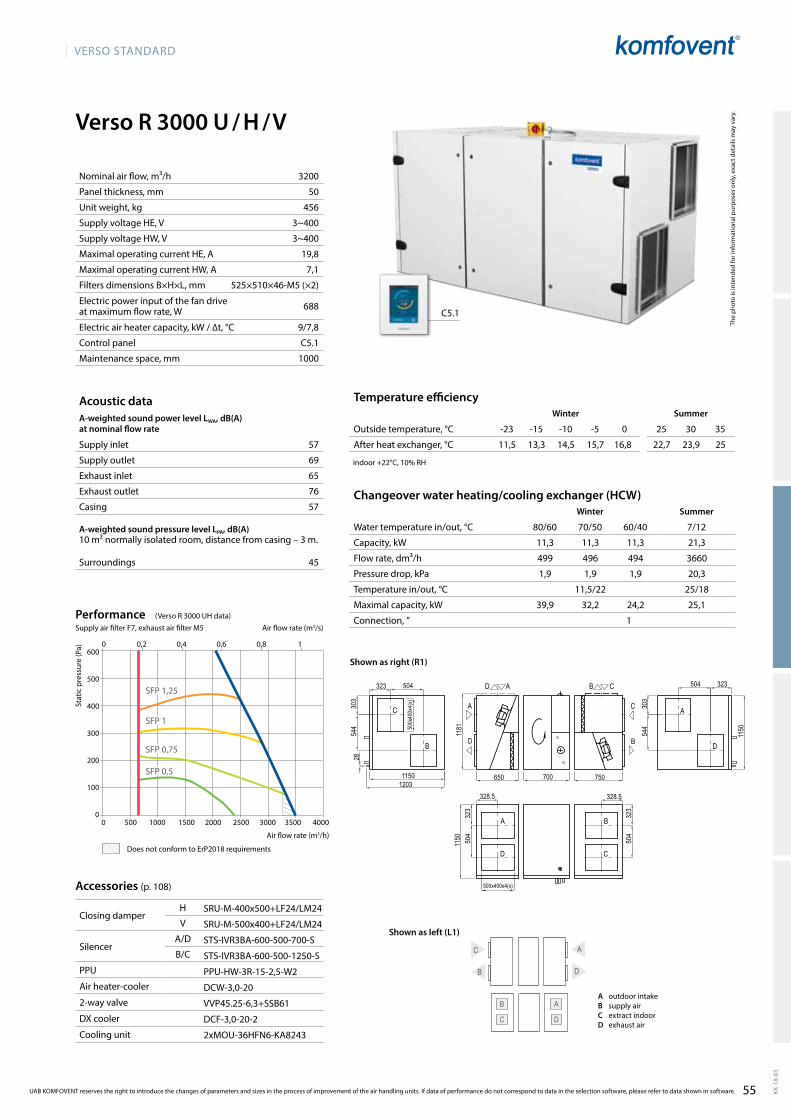
VERSO StandaRd
55 KK-1
8-03
Verso R 3000 U / H / V
3200
50
456
3~400
3~400
19,8
7,1
525×510×46-M5 (×2)
688
9/7,8
C5.1
1000
57
69
65
76
57
45
C
B A
D
B
A C
D
SRU-M-400x500+LF24/LM24
SRU-M-500x400+LF24/LM24
STS-IVR3BA-600-500-700-S
STS-IVR3BA-600-500-1250-S
PPU-HW-3R-15-2,5-W2
DCW-3,0-20
VVP45.25-6,3+SSB61
DCF-3,0-20-2
2xMOU-36HFN6-KA8243
C5.1
11,5 13,3 14,5 15,7 16,8 22,7 23,9 25
11,3 11,3 11,3 21,3
499 496 494 3660
1,9 1,9 1,9 20,3
11,5/22 25/18
39,9 32,2 24,2 25,1
1
1181
700650 750
1150 50
432
3
328.5 328.5
504
323
323
303
1150
544
504
1203
303
544
323504
1150
Verso_R_3000_R1
C
B
A
D
A
D
B
C
C
B
A
D
AD CB
28
500x400x4(x)
500x
400x
4(x)
600
500
400
300
200
100
0
0 0,2 0,4 0,6 0,8 1
SFP 1,25
SFP 0,5
SFP 1
SFP 0,75
0 500 1000 1500 2000 2500 3000 3500 4000
Accessories (p. 108)
Closing damperH
V
SilencerA/D
B/C
PPU
Air heater-cooler
2-way valve
DX cooler
Cooling unit
UAB KOMFOVENT reserves the right to introduce the changes of parameters and sizes in the process of improvement of the air handling units. If data of performance do not correspond to data in the selection software, please refer to data shown in software.
The
phot
o is
inte
nded
for i
nfor
mat
iona
l pur
pose
s on
ly, e
xact
det
ails
may
var
y.
Acoustic dataA-weighted sound power level LwA, dB(A)at nominal flow rate
Supply inlet
Supply outlet
Exhaust inlet
Exhaust outlet
Casing
A-weighted sound pressure level LPA, dB(A) 10 m² normally isolated room, distance from casing – 3 m.
Surroundings
Changeover water heating/cooling exchanger (HCW)Winter Summer
Water temperature in/out, °C 80/60 70/50 60/40 7/12
Capacity, kW
Flow rate, dm³/h
Pressure drop, kPa
Temperature in/out, °C
Maximal capacity, kW
Connection, ”
Stat
ic p
ress
ure
(Pa)
Air flow rate (m3/h)
Temperature efficiencyWinter Summer
Outside temperature, °C -23 -15 -10 -5 0 25 30 35
After heat exchanger, °C
indoor +22°C, 10% RH
Nominal air flow, m³/h
Panel thickness, mm
Unit weight, kg
Supply voltage HE, V
Supply voltage HW, V
Maximal operating current HE, A
Maximal operating current HW, A
Filters dimensions B×H×L, mm
Electric power input of the fan drive at maximum flow rate, W
Electric air heater capacity, kW / ∆t, °C
Control panel
Maintenance space, mm
Air flow rate (m3/s)
PerformanceSupply air filter F7, exhaust air filter M5
Does not conform to ErP2018 requirements
A outdoor intakeB supply airC extract indoorD exhaust air
Shown as right (R1)
Shown as left (L1)
(VersoR3000UHdata)
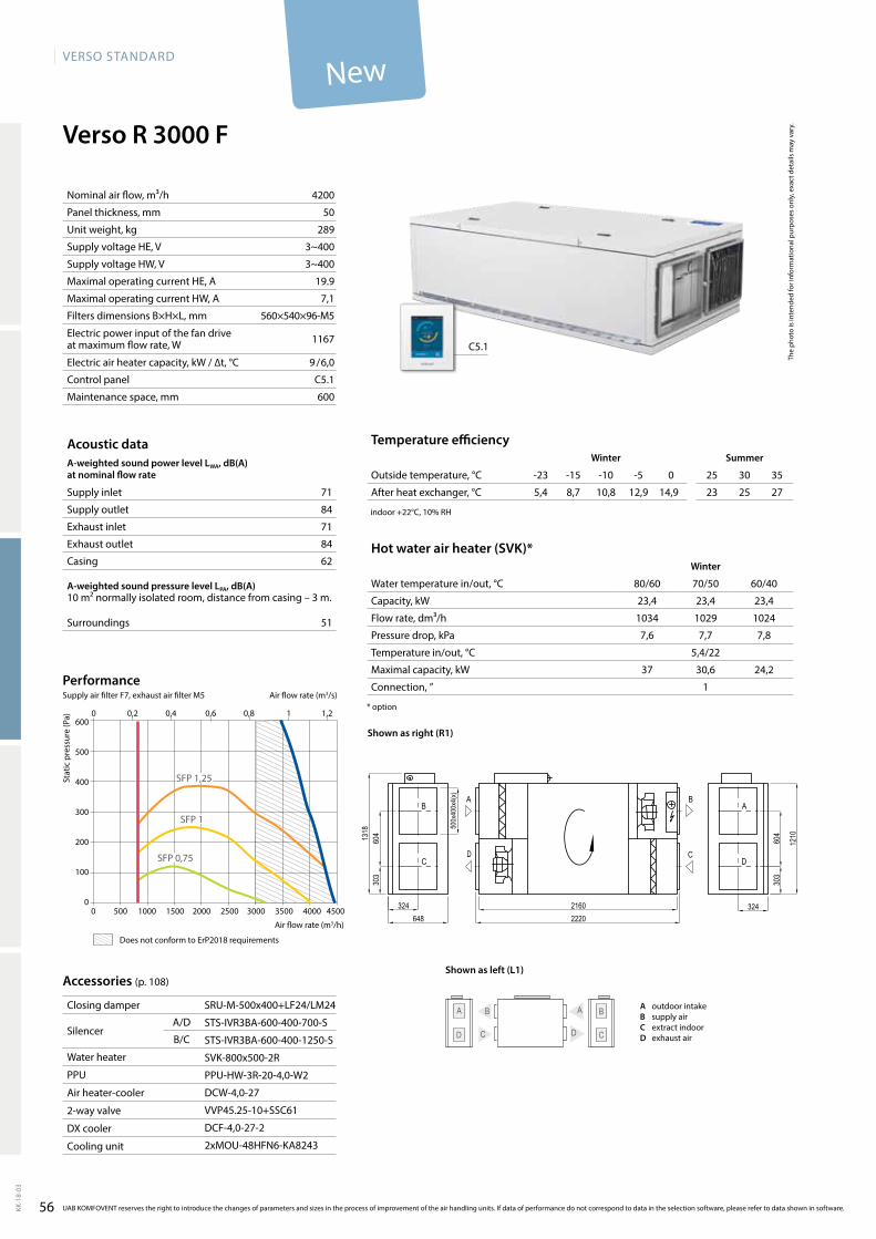
56
VERSO StandaRd
KK-1
8-03
4200
50
289
3~400
3~400
19.9
7,1
560×540×96-M5
1167
9 / 6,0
C5.1
600
71
84
71
84
62
51
C5.1
Verso R 3000 F
5,4 8,7 10,8 12,9 14,9 23 25 27
23,4 23,4 23,4
1034 1029 1024
7,6 7,7 7,8
5,4/22
37 30,6 24,2
1
SRU-M-500x400+LF24/LM24
STS-IVR3BA-600-400-700-S
STS-IVR3BA-600-400-1250-S
SVK-800x500-2R
PPU-HW-3R-20-4,0-W2
DCW-4,0-27
VVP45.25-10+SSC61
DCF-4,0-27-2
2xMOU-48HFN6-KA8243
600
500
400
300
200
100
00 500 1000 1500 2000 2500 3000 3500 4000 4500
0 0,2 0,4 0,6 0,8 1 1,2
SFP 0,75
SFP 1
SFP 1,25
C
BA
CD
BA
D
B
C D
A
Verso_R_3000_R1
A
D
B
C
2160648
1210
2220324
303
604
324
303
6041318 50
0x40
0x4(
x)
The
phot
o is
inte
nded
for i
nfor
mat
iona
l pur
pose
s on
ly, e
xact
det
ails
may
var
y.
Acoustic dataA-weighted sound power level LwA, dB(A)at nominal flow rate
Supply inlet
Supply outlet
Exhaust inlet
Exhaust outlet
Casing
A-weighted sound pressure level LPA, dB(A) 10 m² normally isolated room, distance from casing – 3 m.
Surroundings
Nominal air flow, m³/h
Panel thickness, mm
Unit weight, kg
Supply voltage HE, V
Supply voltage HW, V
Maximal operating current HE, A
Maximal operating current HW, A
Filters dimensions B×H×L, mm
Electric power input of the fan drive at maximum flow rate, W
Electric air heater capacity, kW / ∆t, °C
Control panel
Maintenance space, mm
Stat
ic p
ress
ure
(Pa)
Air flow rate (m3/h)
Temperature efficiencywinter Summer
Outside temperature, °C -23 -15 -10 -5 0 25 30 35
After heat exchanger, °C
indoor +22°C, 10% RH
Hot water air heater (SVK)*winter
Water temperature in/out, °C 80/60 70/50 60/40
Capacity, kW
Flow rate, dm³/h
Pressure drop, kPa
Temperature in/out, °C
Maximal capacity, kW
Connection, ”
* option
UAB KOMFOVENT reserves the right to introduce the changes of parameters and sizes in the process of improvement of the air handling units. If data of performance do not correspond to data in the selection software, please refer to data shown in software.
Air flow rate (m3/s)
PerformanceSupply air filter F7, exhaust air filter M5
Accessories (p. 108)
Closing damper
SilencerA/D
B/C
Water heater
PPU
Air heater-cooler
2-way valve
DX cooler
Cooling unit
Shown as left (L1)
Shown as right (R1)
A outdoor intakeB supply airC extract indoorD exhaust air
Does not conform to ErP2018 requirements
New
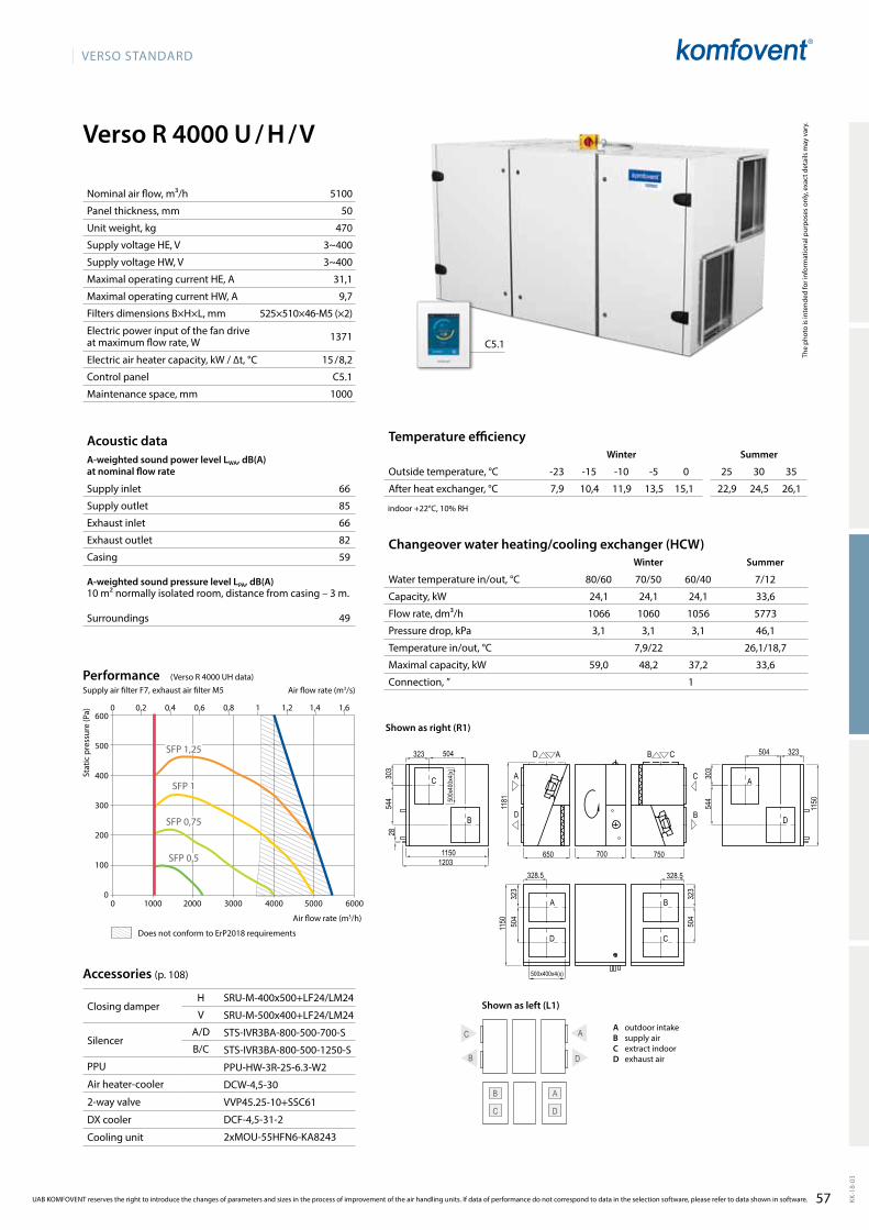
VERSO StandaRd
57 KK-1
8-03
Verso R 4000 U / H / V
5100
50
470
3~400
3~400
31,1
9,7
525×510×46-M5 (×2)
1371
15 / 8,2
C5.1
1000
66
85
66
82
59
49
C
B A
D
B
A C
D
SRU-M-400x500+LF24/LM24
SRU-M-500x400+LF24/LM24
STS-IVR3BA-800-500-700-S
STS-IVR3BA-800-500-1250-S
PPU-HW-3R-25-6.3-W2
DCW-4,5-30
VVP45.25-10+SSC61
DCF-4,5-31-2
2xMOU-55HFN6-KA8243
C5.1
7,9 10,4 11,9 13,5 15,1 22,9 24,5 26,1
24,1 24,1 24,1 33,6
1066 1060 1056 5773
3,1 3,1 3,1 46,1
7,9/22 26,1/18,7
59,0 48,2 37,2 33,6
1
1181
700650 750
1150 50
432
3
328.5 328.5
504
323
323
303
1150
544
504
1203
303
544
323504
1150
Verso_R_3000_R1
C
B
A
D
A
D
B
C
C
B
A
D
AD CB
28
500x400x4(x)
500x
400x
4(x)
600
500
400
300
200
100
00 1000 2000 3000 4000 5000 6000
SFP 1,25
SFP 0,5
SFP 1
SFP 0,75
0 0,2 0,4 0,6 0,8 1 1,2 1,4 1,6
Accessories (p. 108)
Closing damperH
V
SilencerA/D
B/C
PPU
Air heater-cooler
2-way valve
DX cooler
Cooling unit
UAB KOMFOVENT reserves the right to introduce the changes of parameters and sizes in the process of improvement of the air handling units. If data of performance do not correspond to data in the selection software, please refer to data shown in software.
The
phot
o is
inte
nded
for i
nfor
mat
iona
l pur
pose
s on
ly, e
xact
det
ails
may
var
y.
Acoustic dataA-weighted sound power level LwA, dB(A)at nominal flow rate
Supply inlet
Supply outlet
Exhaust inlet
Exhaust outlet
Casing
A-weighted sound pressure level LPA, dB(A) 10 m² normally isolated room, distance from casing – 3 m.
Surroundings
Changeover water heating/cooling exchanger (HCW)Winter Summer
Water temperature in/out, °C 80/60 70/50 60/40 7/12
Capacity, kW
Flow rate, dm³/h
Pressure drop, kPa
Temperature in/out, °C
Maximal capacity, kW
Connection, ”
Stat
ic p
ress
ure
(Pa)
Air flow rate (m3/h)
Temperature efficiencyWinter Summer
Outside temperature, °C -23 -15 -10 -5 0 25 30 35
After heat exchanger, °C
indoor +22°C, 10% RH
Nominal air flow, m³/h
Panel thickness, mm
Unit weight, kg
Supply voltage HE, V
Supply voltage HW, V
Maximal operating current HE, A
Maximal operating current HW, A
Filters dimensions B×H×L, mm
Electric power input of the fan drive at maximum flow rate, W
Electric air heater capacity, kW / ∆t, °C
Control panel
Maintenance space, mm
Air flow rate (m3/s)
PerformanceSupply air filter F7, exhaust air filter M5
A outdoor intakeB supply airC extract indoorD exhaust air
Shown as right (R1)
Shown as left (L1)
Does not conform to ErP2018 requirements
(VersoR4000UHdata)
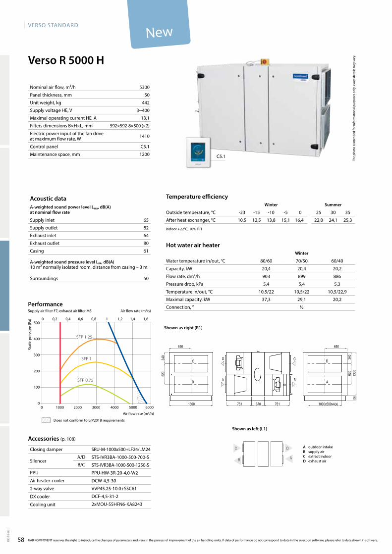
58
VERSO StandaRd
KK-1
8-03
Verso R 5000 H
5300
50
442
3~400
13,1
592×592-8×500 (×2)
1410
C5.1
1200
65
82
64
80
61
50
SRU-M-1000x500+LF24/LM24
STS-IVR3BA-1000-500-700-S
STS-IVR3BA-1000-500-1250-S
PPU-HW-3R-20-4,0-W2
DCW-4,5-30
VVP45.25-10.0+SSC61
DCF-4,5-31-2
2xMOU-55HFN6-KA8243
C5.1
10,5 12,5 13,8 15,1 16,4 22,8 24,1 25,3
20,4 20,4 20,2
903 899 886
5,4 5,4 5,3
10,5/22 10,5/22 10,5/22,9
37,3 29,1 20,2
½
500
400
300
200
100
00 1000 2000 3000 4000 5000 6000
0 0,2 0,4 0,6 0,8 1 1,2 1,4 1,6
SFP 0,75
SFP 1
SFP 1,25
B A
C D
Verso_R_5000_R1
D
A
C
B A B
CD
1300 751 370 751
1300
1000x500x4(x)
650
340
620
340
620
150
650Th
e ph
oto
is in
tend
ed fo
r inf
orm
atio
nal p
urpo
ses
only
, exa
ct d
etai
ls m
ay v
ary.
Acoustic dataA-weighted sound power level LwA, dB(A)at nominal flow rate
Supply inlet
Supply outlet
Exhaust inlet
Exhaust outlet
Casing
A-weighted sound pressure level LPA, dB(A) 10 m² normally isolated room, distance from casing – 3 m.
Surroundings
Nominal air flow, m³/h
Panel thickness, mm
Unit weight, kg
Supply voltage HE, V
Maximal operating current HE, A
Filters dimensions B×H×L, mm
Electric power input of the fan drive at maximum flow rate, W
Control panel
Maintenance space, mm
Stat
ic p
ress
ure
(Pa)
Air flow rate (m3/s)
Air flow rate (m3/h)
PerformanceSupply air filter F7, exhaust air filter M5
Accessories (p. 108)
Closing damper
SilencerA/D
B/C
PPU
Air heater-cooler
2-way valve
DX cooler
Cooling unit
Temperature efficiencywinter Summer
Outside temperature, °C -23 -15 -10 -5 0 25 30 35
After heat exchanger, °C
indoor +22°C, 10% RH
Hot water air heaterwinter
Water temperature in/out, °C 80/60 70/50 60/40
Capacity, kW
Flow rate, dm³/h
Pressure drop, kPa
Temperature in/out, °C
Maximal capacity, kW
Connection, ”
UAB KOMFOVENT reserves the right to introduce the changes of parameters and sizes in the process of improvement of the air handling units. If data of performance do not correspond to data in the selection software, please refer to data shown in software.
A outdoor intakeB supply airC extract indoorD exhaust air
Shown as right (R1)
Shown as left (L1)
Does not conform to ErP2018 requirements
New
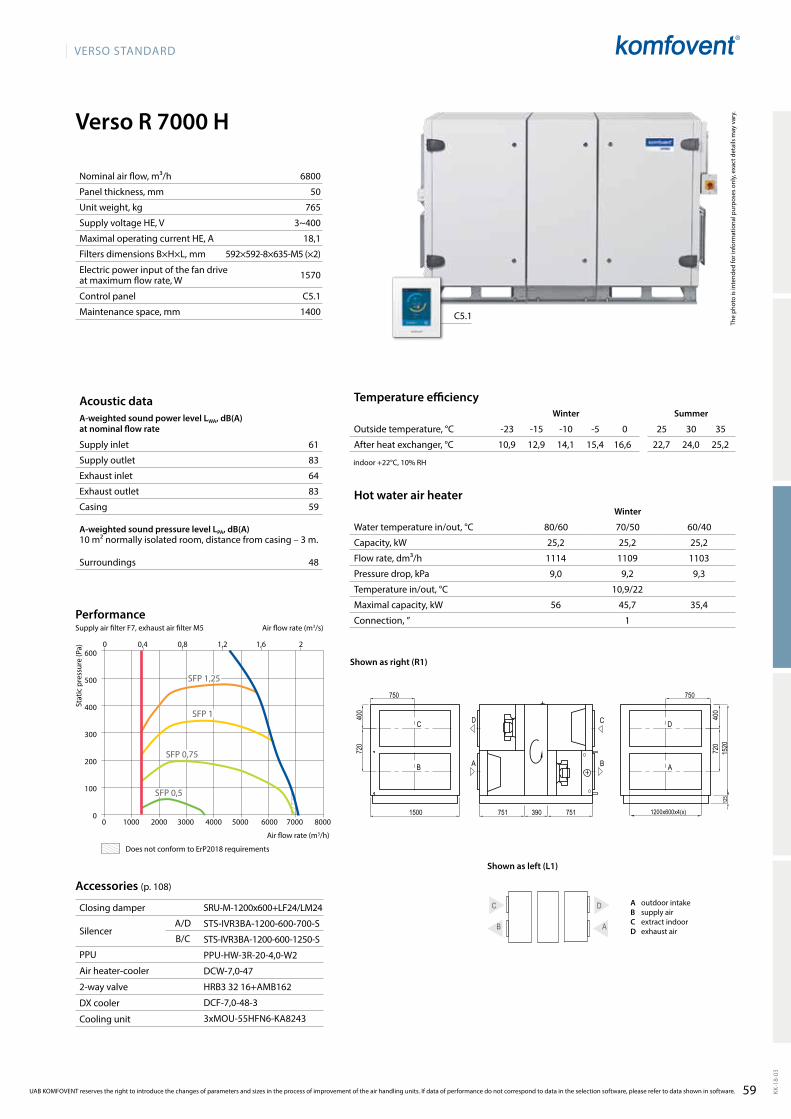
59
VERSO StandaRd
KK-1
8-03
Verso R 7000 H
6800
50
765
3~400
18,1
592×592-8×635-M5 (×2)
1570
C5.1
1400
61
83
64
83
59
48
B A
C DSRU-M-1200x600+LF24/LM24
STS-IVR3BA-1200-600-700-S
STS-IVR3BA-1200-600-1250-S
PPU-HW-3R-20-4,0-W2
DCW-7,0-47
HRB33216+AMB162
DCF-7,0-48-3
3xMOU-55HFN6-KA8243
C5.1
10,9 12,9 14,1 15,4 16,6 22,7 24,0 25,2
25,2 25,2 25,2
1114 1109 1103
9,0 9,2 9,3
10,9/22
56 45,7 35,4
1
600
500
400
300
200
100
00 1000 2000 3000 4000 5000 6000 7000 8000
SFP 1,25
SFP 0,5
SFP 1
SFP 0,75
0 0,4 0,8 1,2 1,6 2
Verso_R_7000_R1
D
A
C
B A B
CD
1500 751 390 751
1520
750
400
720
400
720
750
125
1200x600x4(x)
The
phot
o is
inte
nded
for i
nfor
mat
iona
l pur
pose
s on
ly, e
xact
det
ails
may
var
y.
Acoustic dataA-weighted sound power level LwA, dB(A)at nominal flow rate
Supply inlet
Supply outlet
Exhaust inlet
Exhaust outlet
Casing
A-weighted sound pressure level LPA, dB(A) 10 m² normally isolated room, distance from casing – 3 m.
Surroundings
Nominal air flow, m³/h
Panel thickness, mm
Unit weight, kg
Supply voltage HE, V
Maximal operating current HE, A
Filters dimensions B×H×L, mm
Electric power input of the fan drive at maximum flow rate, W
Control panel
Maintenance space, mm
Stat
ic p
ress
ure
(Pa)
Air flow rate (m3/s)
Air flow rate (m3/h)
PerformanceSupply air filter F7, exhaust air filter M5
Accessories (p. 108)
Closing damper
SilencerA/D
B/C
PPU
Air heater-cooler
2-way valve
DX cooler
Cooling unit
Temperature efficiencyWinter Summer
Outside temperature, °C -23 -15 -10 -5 0 25 30 35
After heat exchanger, °C
indoor +22°C, 10% RH
Hot water air heaterWinter
Water temperature in/out, °C 80/60 70/50 60/40
Capacity, kW
Flow rate, dm³/h
Pressure drop, kPa
Temperature in/out, °C
Maximal capacity, kW
Connection, ”
UAB KOMFOVENT reserves the right to introduce the changes of parameters and sizes in the process of improvement of the air handling units. If data of performance do not correspond to data in the selection software, please refer to data shown in software.
A outdoor intakeB supply airC extract indoorD exhaust air
Shown as right (R1)
Shown as left (L1)
Does not conform to ErP2018 requirements
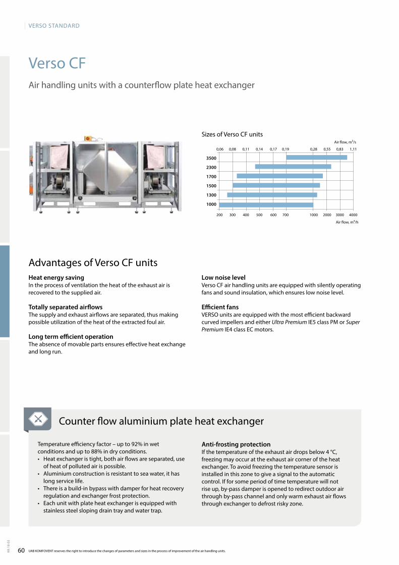
60
VERSO StandaRd
KK-1
8-03
Verso CF
200 300 400 500 600 700 1000 2000 3000 4000
0,06 0,08 0,11 0,14 0,17 0,19 0,28 0,55 0,83 1,11
3500
2300
1700
1500
1300
1000
UAB KOMFOVENT reserves the right to introduce the changes of parameters and sizes in the process of improvement of the air handling units.
Air handling units with a counterflow plate heat exchanger
Sizes of Verso CF units
Air flow, m³/h
Air flow, m³/s
Counter flow aluminium plate heat exchanger
Temperature efficiency factor – up to 92% in wet conditions and up to 88% in dry conditions.• Heatexchangeristight,bothairflowsareseparated,use
of heat of polluted air is possible.• Aluminium construction is resistant to sea water, it has
long service life.• There is a build-in bypass with damper for heat recovery
regulation and exchanger frost protection.• Each unit with plate heat exchanger is equipped with
stainless steel sloping drain tray and water trap.
Anti-frosting protectionIf the temperature of the exhaust air drops below 4 °C, freezing may occur at the exhaust air corner of the heat exchanger. To avoid free zing the temperature sensor is installed in this zone to give a signal to the automatic control. If for some period of time temperature will not rise up, by-pass damper is opened to redirect outdoor air through by-pass channel and only warm exhaust air flows through exchanger to defrost risky zone.
Heat energy savingIn the process of ventilation the heat of the exhaust air is recovered to the supplied air.
Totally separated airflowsThe supply and exhaust airflows are separated, thus making possible utilization of the heat of the extracted foul air.
Long term efficient operationThe absence of movable parts ensures effective heat exchange and long run.
Advantages of Verso CF unitsLow noise levelVerso CF air handling units are equipped with silently operating fans and sound insulation, which ensures low noise level.
Efficient fansVERSO units are equipped with the most efficient backward curved impellers and either Ultra Premium IE5 class PM or Super Premium IE4 class EC motors.
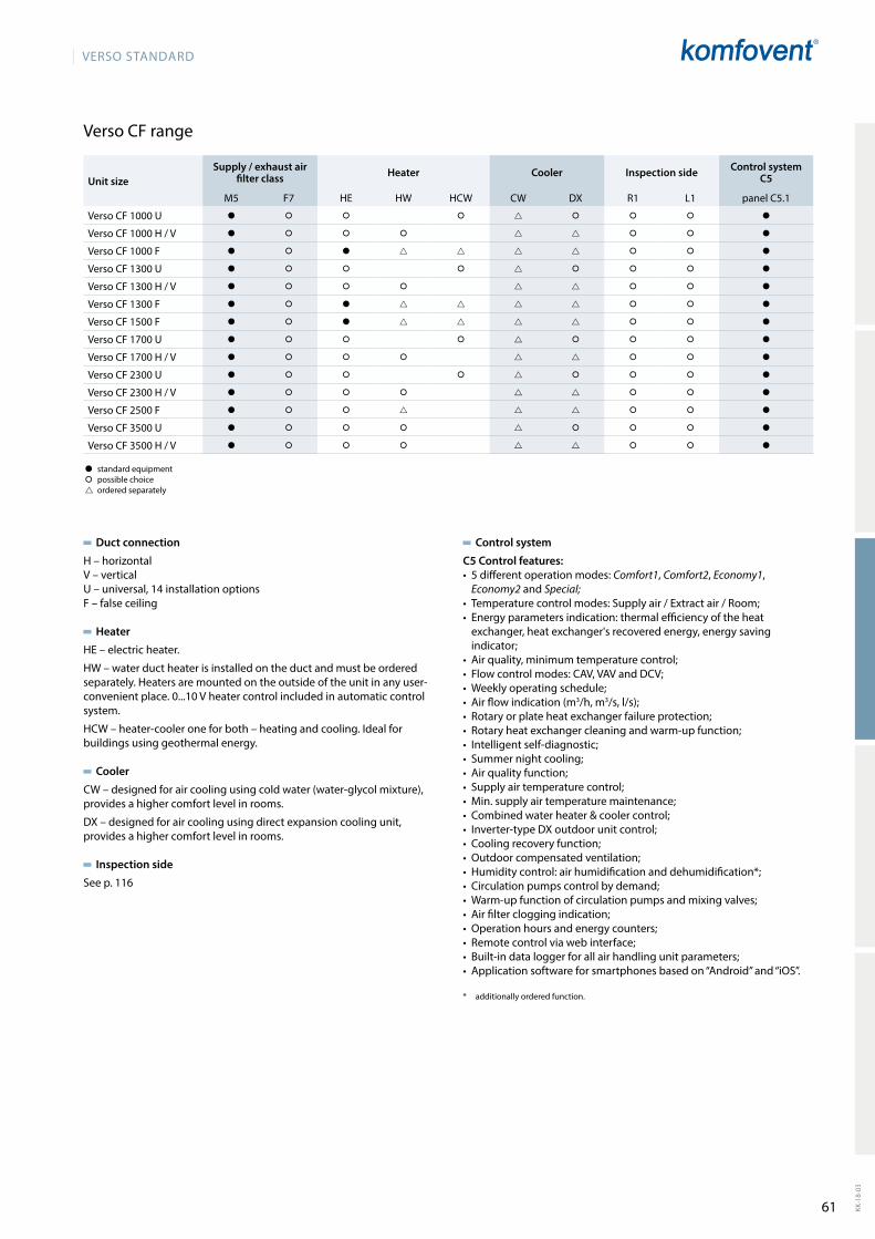
61
VERSO StandaRd
KK-1
8-03
Duct connection
H–horizontalV – verticalU – universal, 14 installation optionsF – false ceiling
Heater
HE–electricheater.
HW–waterductheaterisinstalledontheductandmustbeorderedseparately.Heatersaremountedontheoutsideoftheunitinanyuser-convenient place. 0...10 V heater control included in automatic control system.
HCW–heater-cooleroneforboth–heatingandcooling.Idealforbuildings using geothermal energy.
Cooler
CW – designed for air cooling using cold water (water-glycol mixture), provides a higher comfort level in rooms.
DX – designed for air cooling using direct expansion cooling unit, provides a higher comfort level in rooms.
Inspection side
See p. 116
Control system
C5 Control features:• 5differentoperationmodes:Comfort1, Comfort2, Economy1,
Economy2 and Special;• Temperaturecontrolmodes:Supplyair/Extractair/Room;• Energyparametersindication:thermalefficiencyoftheheat
exchanger, heat exchanger's recovered energy, energy saving indicator;
• Airquality,minimumtemperaturecontrol;• Flowcontrolmodes:CAV,VAVandDCV;• Weeklyoperatingschedule;• Airflowindication(m3/h, m3/s,l/s);• Rotaryorplateheatexchangerfailureprotection;• Rotaryheatexchangercleaningandwarm-upfunction;• Intelligentself-diagnostic;• Summernightcooling;• Airqualityfunction;• Supplyairtemperaturecontrol;• Min.supplyairtemperaturemaintenance;• Combinedwaterheater&coolercontrol;• Inverter-typeDXoutdoorunitcontrol;• Coolingrecoveryfunction;• Outdoorcompensatedventilation;• Humiditycontrol:airhumidificationanddehumidification*;• Circulationpumpscontrolbydemand;• Warm-upfunctionofcirculationpumpsandmixingvalves;• Airfiltercloggingindication;• Operationhoursandenergycounters;• Remotecontrolviawebinterface;• Built-indataloggerforallairhandlingunitparameters;• Applicationsoftwareforsmartphonesbasedon“Android”and“iOS”.
* additionally ordered function.
Verso CF range
� standard equipment� possible choice ordered separately
Unit sizeSupply / exhaust air
filter class Heater Cooler Inspection side Control system C5
M5 F7 HE HW HCW CW DX R1 L1 panel C5.1
Verso CF 1000 U � � � � � � � �
VersoCF1000H/V � � � � � � �
Verso CF 1000 F � � � � � �
Verso CF 1300 U � � � � � � � �
VersoCF1300H/V � � � � � � �
Verso CF 1300 F � � � � � �
Verso CF 1500 F � � � � � �
Verso CF 1700 U � � � � � � � �
VersoCF1700H/V � � � � � � �
Verso CF 2300 U � � � � � � � �
VersoCF2300H/V � � � � � � �
Verso CF 2500 F � � � � � �
Verso CF 3500 U � � � � � � � �
VersoCF3500H/V � � � � � � �
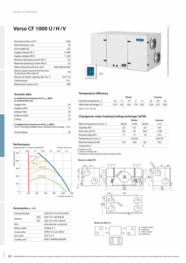
62
VERSO StandaRd
KK-1
8-03
Verso CF 1000 U / H / V
56
73
56
73
53
42
0 200 400 600 800 1000 1200
0 0,05 0,1 0,15 0,2 0,25 0,3500
400
300
200
100
0
SFP 0,75
SFP 1
SFP 1,25
SFP 0,5
15,9 16,3 16,9 17,6 18,2 22,6 23,7 24,9
2,0 2,0 2,0 6,6
90 90 89,5 1139
1,7 1,7 1,8 33,3
15,9/22 24,9/18
13,5 10,8 8,2 10,2
½
AGUJ-M-315+LF24/LM24
AGS-315-100-900-M
AGS-315-100-1200-M
PPU-HW-3R-15-0,63-W1
DCW-0,7-5
VVP47.15-2,5+SSP61
DCF-0,7-5
MOU-18HFN6-KA8243
B
A C
D
A C
B C
A D
D B
C5.1
1050
50
225
3~400
1~230
9,5
3,3
800×400×46-M5
165
4,5 / 11,9
C5.1
800
A
D
Verso_CF_1000_R1
A
D
C
B
C
B
AD CB
C
B
A
D
18101960
285
910
372285 372
242
421
905
242
421
910
398
253 1304
253
980
965
15
⌀ 315 (4x)
⌀ 315 (4x)
The
phot
o is
inte
nded
for i
nfor
mat
iona
l pur
pose
s on
ly, e
xact
det
ails
may
var
y.
Acoustic dataA-weighted sound power level LwA, dB(A)at nominal flow rate
Supply inlet
Supply outlet
Exhaust inlet
Exhaust outlet
Casing
A-weighted sound pressure level LPA, dB(A) 10 m² normally isolated room, distance from casing – 3 m.
Surroundings
Changeover water heating/cooling exchanger (HCw)winter Summer
Water temperature in/out, °C 80/60 70/50 60/40 7/12
Capacity, kW
Flow rate, dm³/h
Pressure drop, kPa
Temperature in/out, °C
Maximal capacity, kW
Connection, ”
Stat
ic p
ress
ure
(Pa)
Air flow rate (m3/h)
Accessories (p. 108)
Closing damper
SilencerA/D
B/C
PPU
Water cooler
2-way valve
DX cooler
Cooling unit
Temperature efficiencywinter Summer
Outside temperature, °C -23 -15 -10 -5 0 25 30 35
After heat exchanger, °C
indoor +22°C, 10% RH
Nominal air flow, m³/h
Panel thickness, mm
Unit weight, kg
Supply voltage HE, V
Supply voltage HW, V
Maximal operating current HE, A
Maximal operating current HW, A
Filters dimensions B×H×L, mm
Electric power input of the fan drive at maximum flow rate, W
Electric air heater capacity, kW / ∆t, °C
Control panel
Maintenance space, mm
UAB KOMFOVENT reserves the right to introduce the changes of parameters and sizes in the process of improvement of the air handling units. If data of performance do not correspond to data in the selection software, please refer to data shown in software.
Air flow rate (m3/s)
PerformanceSupply air filter F7, exhaust air filter M5
A outdoor intakeB supply airC extract indoorD exhaust air
Available versions:1)Electricairheater(HE)2)Changeoverwaterheating/coolingexchanger(HCW)
Shown as right (R1)
Shown as left (L1)
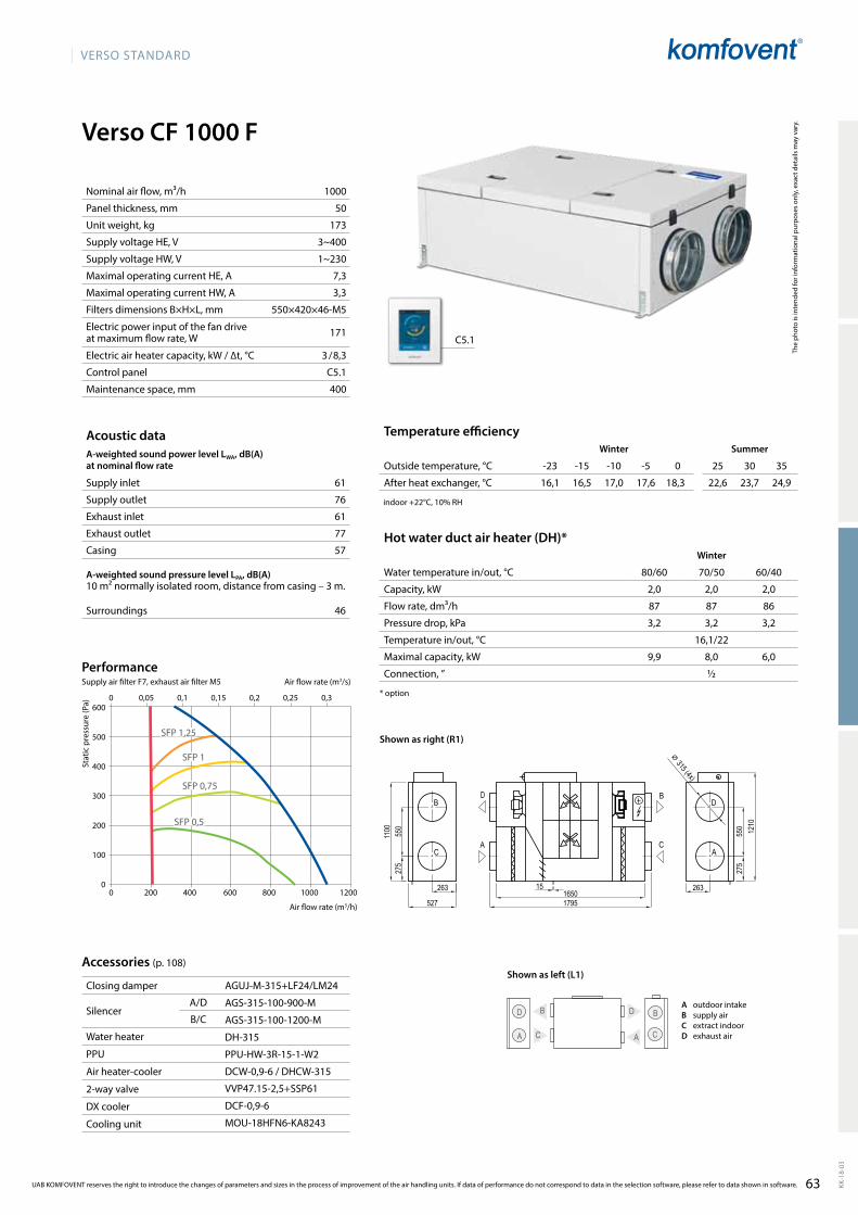
63
VERSO StandaRd
KK-1
8-03
Verso CF 1000 F
61
76
61
77
57
46
1000
50
173
3~400
1~230
7,3
3,3
550×420×46-M5
171
3 / 8,3
C5.1
400
AGUJ-M-315+LF24/LM24
AGS-315-100-900-M
AGS-315-100-1200-M
DH-315
PPU-HW-3R-15-1-W2
DCW-0,9-6/DHCW-315
VVP47.15-2,5+SSP61
DCF-0,9-6
MOU-18HFN6-KA8243
C5.1
C
B D
A A
B
C
D
16,1 16,5 17,0 17,6 18,3 22,6 23,7 24,9
2,0 2,0 2,0
87 87 86
3,2 3,2 3,2
16,1/22
9,9 8,0 6,0
½
0 200 400 600 800 1000 1200
0 0,05 0,1 0,15 0,2 0,25 0,3600
500
400
300
200
100
0
SFP 0,75
SFP 1
SFP 1,25
SFP 0,5
16501795
1210
263
527
275
550
1100
275
550
26315
⌀ 315 (4x)
Verso_CF_1000_R1
D BB D
C AA C
The
phot
o is
inte
nded
for i
nfor
mat
iona
l pur
pose
s on
ly, e
xact
det
ails
may
var
y.
Acoustic dataA-weighted sound power level LwA, dB(A)at nominal flow rate
Supply inlet
Supply outlet
Exhaust inlet
Exhaust outlet
Casing
A-weighted sound pressure level LPA, dB(A) 10 m² normally isolated room, distance from casing – 3 m.
Surroundings
Nominal air flow, m³/h
Panel thickness, mm
Unit weight, kg
Supply voltage HE, V
Supply voltage HW, V
Maximal operating current HE, A
Maximal operating current HW, A
Filters dimensions B×H×L, mm
Electric power input of the fan drive at maximum flow rate, W
Electric air heater capacity, kW / ∆t, °C
Control panel
Maintenance space, mm
Stat
ic p
ress
ure
(Pa)
Air flow rate (m3/h)
Accessories (p. 108)
Closing damper
SilencerA/D
B/C
Water heater
PPU
Air heater-cooler
2-way valve
DX cooler
Cooling unit
Temperature efficiencyWinter Summer
Outside temperature, °C -23 -15 -10 -5 0 25 30 35
After heat exchanger, °C
indoor +22°C, 10% RH
Hot water duct air heater (DH)*Winter
Water temperature in/out, °C 80/60 70/50 60/40
Capacity, kW
Flow rate, dm³/h
Pressure drop, kPa
Temperature in/out, °C
Maximal capacity, kW
Connection, ”
* option
UAB KOMFOVENT reserves the right to introduce the changes of parameters and sizes in the process of improvement of the air handling units. If data of performance do not correspond to data in the selection software, please refer to data shown in software.
Air flow rate (m3/s)
PerformanceSupply air filter F7, exhaust air filter M5
Shown as right (R1)
Shown as left (L1)
A outdoor intakeB supply airC extract indoorD exhaust air
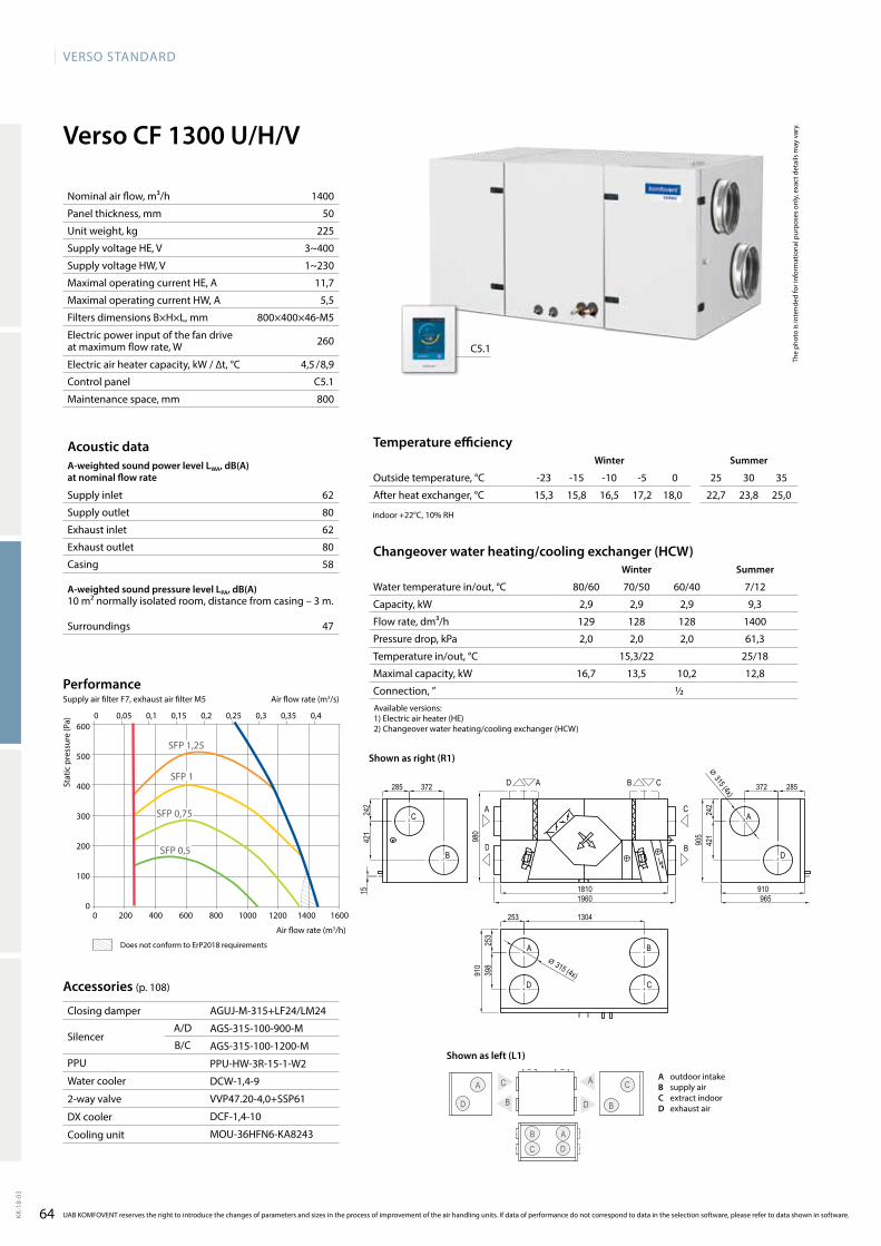
64
VERSO StandaRd
KK-1
8-03
1400
50
225
3~400
1~230
11,7
5,5
800×400×46-M5
260
4,5 / 8,9
C5.1
800
C5.1
62
80
62
80
58
47
AGUJ-M-315+LF24/LM24
AGS-315-100-900-M
AGS-315-100-1200-M
PPU-HW-3R-15-1-W2
DCW-1,4-9
VVP47.20-4,0+SSP61
DCF-1,4-10
MOU-36HFN6-KA8243
15,3 15,8 16,5 17,2 18,0 22,7 23,8 25,0
2,9 2,9 2,9 9,3
129 128 128 1400
2,0 2,0 2,0 61,3
15,3/22 25/18
16,7 13,5 10,2 12,8
½
Verso CF 1300 U/H/V
B
A C
D
A C
B C
A D
D B
A
D
Verso_CF_1000_R1
A
D
C
B
C
B
AD CB
C
B
A
D
18101960
285
910
372285 372
242
421
905
242
421
910
398
253 1304
253
980
965
15
⌀ 315 (4x)
⌀ 315 (4x)
0 200 400 600 800 1000 1200 1400 1600
600
500
400
300
200
100
0
0 0,05 0,1 0,15 0,2 0,25 0,3 0,35 0,4
SFP 0,75
SFP 1
SFP 1,25
SFP 0,5
The
phot
o is
inte
nded
for i
nfor
mat
iona
l pur
pose
s on
ly, e
xact
det
ails
may
var
y.
Acoustic dataA-weighted sound power level LwA, dB(A)at nominal flow rate
Supply inlet
Supply outlet
Exhaust inlet
Exhaust outlet
Casing
A-weighted sound pressure level LPA, dB(A) 10 m² normally isolated room, distance from casing – 3 m.
Surroundings
Changeover water heating/cooling exchanger (HCw)winter Summer
Water temperature in/out, °C 80/60 70/50 60/40 7/12
Capacity, kW
Flow rate, dm³/h
Pressure drop, kPa
Temperature in/out, °C
Maximal capacity, kW
Connection, ”
Stat
ic p
ress
ure
(Pa)
Air flow rate (m3/h)
Accessories (p. 108)
Closing damper
SilencerA/D
B/C
PPU
Water cooler
2-way valve
DX cooler
Cooling unit
Temperature efficiencywinter Summer
Outside temperature, °C -23 -15 -10 -5 0 25 30 35
After heat exchanger, °C
indoor +22°C, 10% RH
Nominal air flow, m³/h
Panel thickness, mm
Unit weight, kg
Supply voltage HE, V
Supply voltage HW, V
Maximal operating current HE, A
Maximal operating current HW, A
Filters dimensions B×H×L, mm
Electric power input of the fan drive at maximum flow rate, W
Electric air heater capacity, kW / ∆t, °C
Control panel
Maintenance space, mm
UAB KOMFOVENT reserves the right to introduce the changes of parameters and sizes in the process of improvement of the air handling units. If data of performance do not correspond to data in the selection software, please refer to data shown in software.
Air flow rate (m3/s)
PerformanceSupply air filter F7, exhaust air filter M5
Available versions:1)Electricairheater(HE)2)Changeoverwaterheating/coolingexchanger(HCW)
Shown as right (R1)
Does not conform to ErP2018 requirements
A outdoor intakeB supply airC extract indoorD exhaust air
Shown as left (L1)
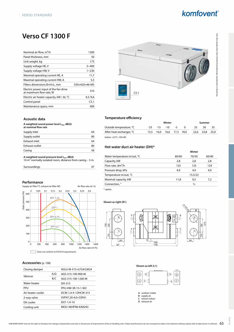
65
VERSO StandaRd
KK-1
8-03
Verso CF 1300 F
64
80
64
80
58
47
1300
50
175
3~400
1~230
11,7
5,5
550×420×46-M5
310
4,5 / 9,6
C5.1
400
AGUJ-M-315+LF24/LM24
AGS-315-100-900-M
AGS-315-100-1200-M
DH-315
PPU-HW-3R-15-1-W2
DCW-1,4-9/DHCW-315
VVP47.20-4,0+SSP61
DCF-1,4-10
MOU-36HFN6-KA8243
C5.1
15,5 16,0 16,6 17,3 18,0 22,6 23,8 25,0
2,8 2,8 2,8
125 125 124
4,9 4,9 4,9
15,5/22
11,8 9,5 7,2
½
0 200 400 600 800 1000 1200 1400 1600
600
500
400
300
200
100
0
SFP 1,25
SFP 1
SFP 0,75
SFP 0,5
0 0,05 0,1 0,15 0,2 0,25 0,3 0,35 0,4
16501795
1210
263
527
275
550
1100
275
550
26315
⌀ 315 (4x)
Verso_CF_1000_R1
D BB D
C AA C
C
B D
A A
B
C
D
The
phot
o is
inte
nded
for i
nfor
mat
iona
l pur
pose
s on
ly, e
xact
det
ails
may
var
y.
Acoustic dataA-weighted sound power level LwA, dB(A)at nominal flow rate
Supply inlet
Supply outlet
Exhaust inlet
Exhaust outlet
Casing
A-weighted sound pressure level LPA, dB(A) 10 m² normally isolated room, distance from casing – 3 m.
Surroundings
Nominal air flow, m³/h
Panel thickness, mm
Unit weight, kg
Supply voltage HE, V
Supply voltage HW, V
Maximal operating current HE, A
Maximal operating current HW, A
Filters dimensions B×H×L, mm
Electric power input of the fan drive at maximum flow rate, W
Electric air heater capacity, kW / ∆t, °C
Control panel
Maintenance space, mm
Stat
ic p
ress
ure
(Pa)
Air flow rate (m3/h)
Accessories (p. 108)
Closing damper
SilencerA/D
B/C
Water heater
PPU
Air heater-cooler
2-way valve
DX cooler
Cooling unit
Temperature efficiencyWinter Summer
Outside temperature, °C -23 -15 -10 -5 0 25 30 35
After heat exchanger, °C
indoor +22°C, 10% RH
Hot water duct air heater (DH)*Winter
Water temperature in/out, °C 80/60 70/50 60/40
Capacity, kW
Flow rate, dm³/h
Pressure drop, kPa
Temperature in/out, °C
Maximal capacity, kW
Connection, ”
* option
UAB KOMFOVENT reserves the right to introduce the changes of parameters and sizes in the process of improvement of the air handling units. If data of performance do not correspond to data in the selection software, please refer to data shown in software.
Air flow rate (m3/s)
PerformanceSupply air filter F7, exhaust air filter M5
Does not conform to ErP2018 requirements
Shown as right (R1)
Shown as left (L1)
A outdoor intakeB supply airC extract indoorD exhaust air
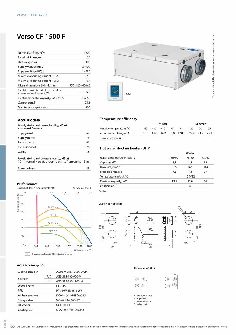
66
VERSO StandaRd
KK-1
8-03
Verso CF 1500 F
62
76
61
76
58
48
1600
50
190
3~400
1~230
12,9
6,7
550×420×46-M5
420
4,5 / 7,8
C5.1
400
AGUJ-M-315+LF24/LM24
AGS-315-100-900-M
AGS-315-100-1200-M
DH-315
PPU-HW-3R-15-1-W2
DCW-1,6-11/DHCW-315
VVP47.20-4,0+SSP61
DCF-1,6-11
MOU-36HFN6-KA8243
C5.1
15,0 15,6 16,2 17,0 17,8 22,7 23,9 25,1
3,8 3,8 3,8
165 165 164
7,3 7,3 7,4
15,0/22
13,5 10,8 8,2
½
0 300 600 900 1200 1500 1800
600
500
400
300
200
100
0
0 0,1 0,2 0,3 0,4 0,5
SFP 1,25
SFP 0,75
SFP 0,5
SFP 1
16501795
1210
263
527
275
550
1100
275
550
26315
⌀ 315 (4x)
Verso_CF_1000_R1
D BB D
C AA C
C
B D
A A
B
C
D
The
phot
o is
inte
nded
for i
nfor
mat
iona
l pur
pose
s on
ly, e
xact
det
ails
may
var
y.
Acoustic dataA-weighted sound power level LwA, dB(A)at nominal flow rate
Supply inlet
Supply outlet
Exhaust inlet
Exhaust outlet
Casing
A-weighted sound pressure level LPA, dB(A) 10 m² normally isolated room, distance from casing – 3 m.
Surroundings
Nominal air flow, m³/h
Panel thickness, mm
Unit weight, kg
Supply voltage HE, V
Supply voltage HW, V
Maximal operating current HE, A
Maximal operating current HW, A
Filters dimensions B×H×L, mm
Electric power input of the fan drive at maximum flow rate, W
Electric air heater capacity, kW / ∆t, °C
Control panel
Maintenance space, mm
Stat
ic p
ress
ure
(Pa)
Air flow rate (m3/h)
Accessories (p. 108)
Closing damper
SilencerA/D
B/C
Water heater
PPU
Air heater-cooler
2-way valve
DX cooler
Cooling unit
Temperature efficiencywinter Summer
Outside temperature, °C -23 -15 -10 -5 0 25 30 35
After heat exchanger, °C
indoor +22°C, 10% RH
Hot water duct air heater (DH)*winter
Water temperature in/out, °C 80/60 70/50 60/40
Capacity, kW
Flow rate, dm³/h
Pressure drop, kPa
Temperature in/out, °C
Maximal capacity, kW
Connection, ”
* option
UAB KOMFOVENT reserves the right to introduce the changes of parameters and sizes in the process of improvement of the air handling units. If data of performance do not correspond to data in the selection software, please refer to data shown in software.
Air flow rate (m3/s)
PerformanceSupply air filter F7, exhaust air filter M5
Does not conform to ErP2018 requirements
Shown as right (R1)
Shown as left (L1)
A outdoor intakeB supply airC extract indoorD exhaust air
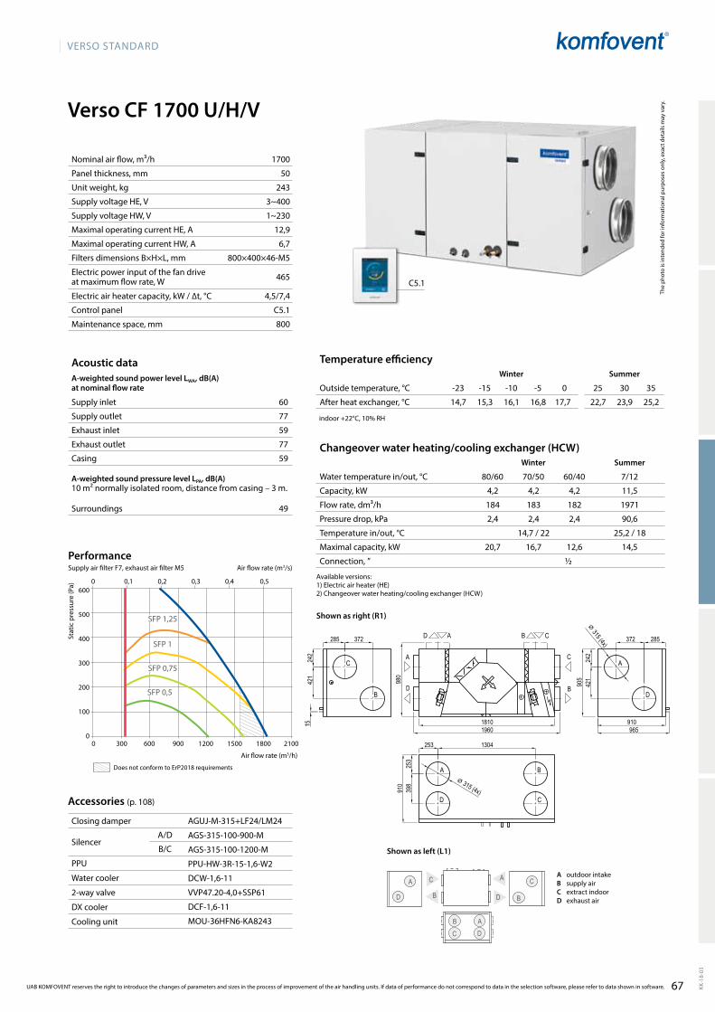
67
VERSO StandaRd
KK-1
8-03
Verso CF 1700 U/H/V
60
77
59
77
59
49
1700
50
243
3~400
1~230
12,9
6,7
800×400×46-M5
465
4,5/7,4
C5.1
800
AGUJ-M-315+LF24/LM24
AGS-315-100-900-M
AGS-315-100-1200-M
PPU-HW-3R-15-1,6-W2
DCW-1,6-11
VVP47.20-4,0+SSP61
DCF-1,6-11
MOU-36HFN6-KA8243
C5.1
4,2 4,2 4,2 11,5
184 183 182 1971
2,4 2,4 2,4 90,6
14,7 / 22 25,2 / 18
20,7 16,7 12,6 14,5
½
14,7 15,3 16,1 16,8 17,7 22,7 23,9 25,2
B
A C
D
A C
B C
A D
D B
A
D
Verso_CF_1000_R1
A
D
C
B
C
B
AD CB
C
B
A
D
18101960
285
910
372285 372
242
421
905
242
421
910
398
253 1304
253
980
965
15
⌀ 315 (4x)
⌀ 315 (4x)
0 0,1 0,2 0,3 0,4 0,5
0 300 600 900 1200 1500 1800 2100
600
500
400
300
200
100
0
SFP 1,25
SFP 1
SFP 0,75
SFP 0,5
The
phot
o is
inte
nded
for i
nfor
mat
iona
l pur
pose
s on
ly, e
xact
det
ails
may
var
y.
Acoustic dataA-weighted sound power level LwA, dB(A)at nominal flow rate
Supply inlet
Supply outlet
Exhaust inlet
Exhaust outlet
Casing
A-weighted sound pressure level LPA, dB(A) 10 m² normally isolated room, distance from casing – 3 m.
Surroundings
Changeover water heating/cooling exchanger (HCW)Winter Summer
Water temperature in/out, °C 80/60 70/50 60/40 7/12
Capacity, kW
Flow rate, dm³/h
Pressure drop, kPa
Temperature in/out, °C
Maximal capacity, kW
Connection, ”
Stat
ic p
ress
ure
(Pa)
Air flow rate (m3/h)
Accessories (p. 108)
Closing damper
SilencerA/D
B/C
PPU
Water cooler
2-way valve
DX cooler
Cooling unit
Temperature efficiencyWinter Summer
Outside temperature, °C -23 -15 -10 -5 0 25 30 35
After heat exchanger, °C
indoor +22°C, 10% RH
Nominal air flow, m³/h
Panel thickness, mm
Unit weight, kg
Supply voltage HE, V
Supply voltage HW, V
Maximal operating current HE, A
Maximal operating current HW, A
Filters dimensions B×H×L, mm
Electric power input of the fan drive at maximum flow rate, W
Electric air heater capacity, kW / ∆t, °C
Control panel
Maintenance space, mm
UAB KOMFOVENT reserves the right to introduce the changes of parameters and sizes in the process of improvement of the air handling units. If data of performance do not correspond to data in the selection software, please refer to data shown in software.
Air flow rate (m3/s)
PerformanceSupply air filter F7, exhaust air filter M5
Available versions:1)Electricairheater(HE)2)Changeoverwaterheating/coolingexchanger(HCW)
Shown as right (R1)
Does not conform to ErP2018 requirements
Shown as left (L1)
A outdoor intakeB supply airC extract indoorD exhaust air
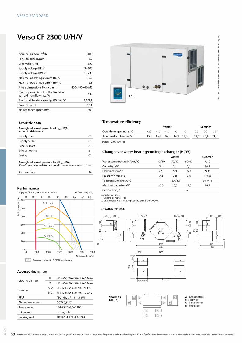
VERSO StandaRd
68KK-1
8-03
63
81
63
81
61
50
2400
50
250
3~400
1~230
16,8
6,3
800×400×46-M5
640
7,5 / 8,7
C5.1
800
Verso CF 2300 U/H/V
C
DB
A
C
A C
D B
D
AB
SRU-M-300x400+LF24/LM24
SRU-M-400x300+LF24/LM24
STS-IVR3BA-600-400-700-S
STS-IVR3BA-600-400-1250-S
PPU-HW-3R-15-1,6-W2
DCW-2,5-17
VVP45.25-6,3+SSB61
DCF-2,5-17
MOU-55HFN6-KA8243
C5.1
15,1 15,8 16,1 16,9 17,8 22,5 23,4 24,3
5,1 5,1 5,1 14,2
225 224 223 2439
2,8 2,8 2,8 134,8
15,4/22 24,3/18
25,3 20,3 15,3 16,7
½
Verso_CF_2300_R1
A
D
C
B
AD CB
A
D
C
B
A B
D C
20002060
910
905
910
935
965
239
398
416
239
416
398262
281
250
1438
403
262
15
400x300x4(x)
400x
300x
4(x)
0 500 1000 1500 2000 2500 3000
600
500
400
300
200
100
0
0 0,1 0,2 0,3 0,4 0,5 0,6 0,7 0,8
SFP 1,25
SFP 0,75
SFP 0,5
SFP 1
Accessories (p. 108)
Closing damperH
V
SilencerA/D
B/C
PPU
Air heater-cooler
2-way valve
DX cooler
Cooling unit
UAB KOMFOVENT reserves the right to introduce the changes of parameters and sizes in the process of improvement of the air handling units. If data of performance do not correspond to data in the selection software, please refer to data shown in software.
The
phot
o is
inte
nded
for i
nfor
mat
iona
l pur
pose
s on
ly, e
xact
det
ails
may
var
y.
Acoustic dataA-weighted sound power level LwA, dB(A)at nominal flow rate
Supply inlet
Supply outlet
Exhaust inlet
Exhaust outlet
Casing
A-weighted sound pressure level LPA, dB(A) 10 m² normally isolated room, distance from casing – 3 m.
Surroundings
Changeover water heating/cooling exchanger (HCw)winter Summer
Water temperature in/out, °C 80/60 70/50 60/40 7/12
Capacity, kW
Flow rate, dm³/h
Pressure drop, kPa
Temperature in/out, °C
Maximal capacity, kW
Connection, ”
Stat
ic p
ress
ure
(Pa)
Air flow rate (m3/h)
Temperature efficiencywinter Summer
Outside temperature, °C -23 -15 -10 -5 0 25 30 35
After heat exchanger, °C
indoor +22°C, 10% RH
Nominal air flow, m³/h
Panel thickness, mm
Unit weight, kg
Supply voltage HE, V
Supply voltage HW, V
Maximal operating current HE, A
Maximal operating current HW, A
Filters dimensions B×H×L, mm
Electric power input of the fan drive at maximum flow rate, W
Electric air heater capacity, kW / ∆t, °C
Control panel
Maintenance space, mm
Air flow rate (m3/s)
PerformanceSupply air filter F7, exhaust air filter M5
Shown as left (L1)
Available versions:1)Electricairheater(HE)2)Changeoverwaterheating/coolingexchanger(HCW)
Shown as right (R1)
A outdoor intakeB supply airC extract indoorD exhaust air
Does not conform to ErP2018 requirements
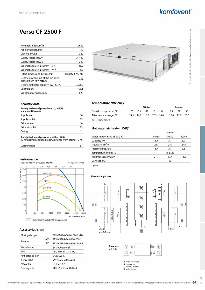
69
VERSO StandaRd
KK-1
8-03
64
83
64
83
62
51
2600
50
340
3~400
1~230
16,9
6,3
888×420×96-M5
607
7,5 / 8,0
C5.1
620
Verso CF 2500 F
15,5 16,0 16,6 17,3 18,0 22,6 23,8 25,0
5,7 5,7 5,7
251 249 248
3,7 3,7 3,8
15,5/22
21,7 17,4 13,0
½
SRU-M-700x300+LF24/LM24
STS-IVR3BA-800-300-700-S
STS-IVR3BA-800-300-1250-S
SVK-700x400-2R
PPU-HW-3R-15-1-W2
DCW-2,5-17
VVP45.25-6,3+SSB61
DCF-2,5-17
MOU-55HFN6-KA8243
0 0,1 0,2 0,3 0,4 0,5 0,6 0,7
0 400 800 1200 1600 2000 2400 2800
700
600
500
400
300
200
100
0
SFP 1,25
SFP 1
SFP 0,75
SFP 0,5
C
B D
A A
B
C
D
Verso_CF_2500_R1
B
C
D
A
D
A
B
C
1850528 1910
28264.5
500
263.5
500
1000
1000
20452000
700x
300x
4(x)
The
phot
o is
inte
nded
for i
nfor
mat
iona
l pur
pose
s on
ly, e
xact
det
ails
may
var
y.
Acoustic dataA-weighted sound power level LwA, dB(A)at nominal flow rate
Supply inlet
Supply outlet
Exhaust inlet
Exhaust outlet
Casing
A-weighted sound pressure level LPA, dB(A) 10 m² normally isolated room, distance from casing – 3 m.
Surroundings
Nominal air flow, m³/h
Panel thickness, mm
Unit weight, kg
Supply voltage HE, V
Supply voltage HW, V
Maximal operating current HE, A
Maximal operating current HW, A
Filters dimensions B×H×L, mm
Electric power input of the fan drive at maximum flow rate, W
Electric air heater capacity, kW / ∆t, °C
Control panel
Maintenance space, mm
Stat
ic p
ress
ure
(Pa)
Air flow rate (m3/h)
Temperature efficiencyWinter Summer
Outside temperature, °C -23 -15 -10 -5 0 25 30 35
After heat exchanger, °C
indoor +22°C, 10% RH
Hot water air heater (SVK)*Winter
Water temperature in/out, °C 80/60 70/50 60/40
Capacity, kW
Flow rate, dm³/h
Pressure drop, kPa
Temperature in/out, °C
Maximal capacity, kW
Connection, ”
* option
UAB KOMFOVENT reserves the right to introduce the changes of parameters and sizes in the process of improvement of the air handling units. If data of performance do not correspond to data in the selection software, please refer to data shown in software.
Air flow rate (m3/s)
PerformanceSupply air filter F7, exhaust air filter M5
Accessories (p. 108)
Closing damper
SilencerA/D
B/C
Water heater
PPU
Air heater-cooler
2-way valve
DX cooler
Cooling unit
Shown as right (R1)
A outdoor intakeB supply airC extract indoorD exhaust air
Does not conform to ErP2018 requirements
Shown as left (L1)
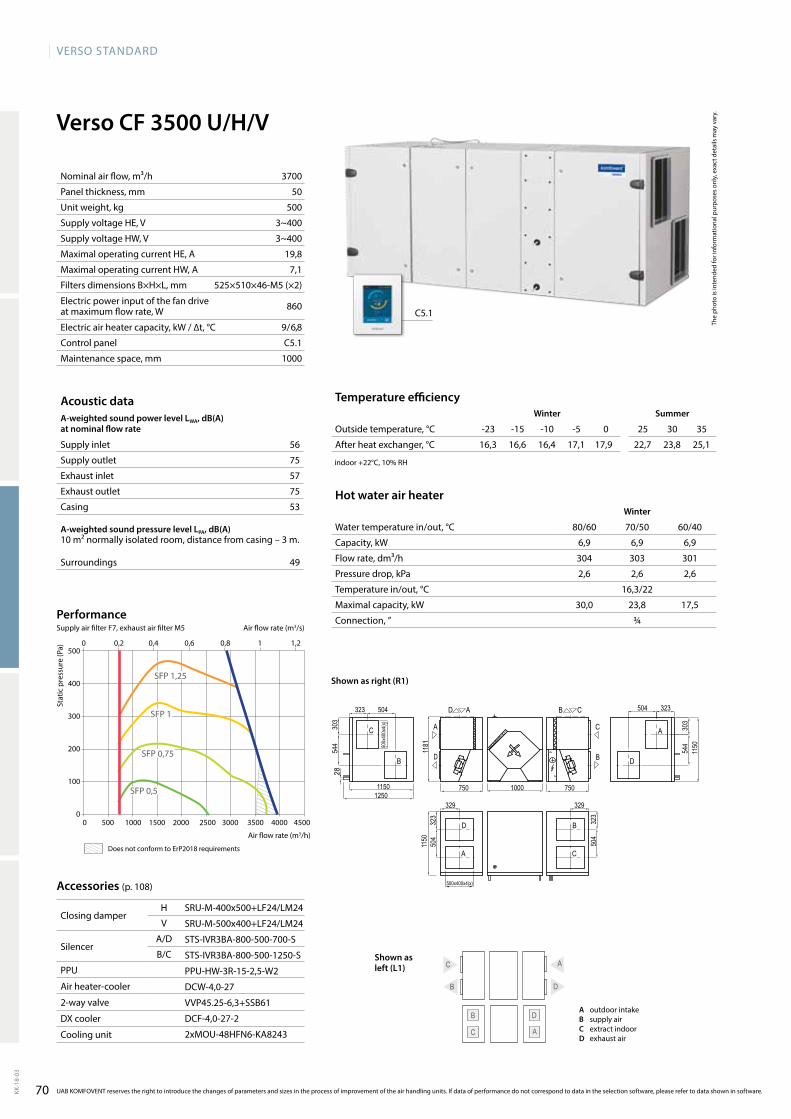
70
VERSO StandaRd
KK-1
8-03
6,9 6,9 6,9
304 303 301
2,6 2,6 2,6
16,3/22
30,0 23,8 17,5
¾
56
75
57
75
53
49
Verso CF 3500 U/H/V
C
B D
A
B
A C
D
SRU-M-400x500+LF24/LM24
SRU-M-500x400+LF24/LM24
STS-IVR3BA-800-500-700-S
STS-IVR3BA-800-500-1250-S
PPU-HW-3R-15-2,5-W2
DCW-4,0-27
VVP45.25-6,3+SSB61
DCF-4,0-27-2
2xMOU-48HFN6-KA8243
C5.1
3700
50
500
3~400
3~400
19,8
7,1
525×510×46-M5 (×2)
860
9 / 6,8
C5.1
1000
16,3 16,6 16,4 17,1 17,9 22,7 23,8 25,1
1181
1000750 750
1150
504
323
329 329
504
323
323
303
1150
544
504
1250
303
544
323504
1150
Verso_CF_3500_R1
C
B
A
D
D
A
B
C
C
B
A
D
AD CB
28
500x400x4(x)
500x
400x
4(x)
0 0,2 0,4 0,6 0,8 1 1,2
0 500 1000 1500 2000 2500 3000 3500 4000 4500
500
400
300
200
100
0
SFP 1,25
SFP 1
SFP 0,75
SFP 0,5
The
phot
o is
inte
nded
for i
nfor
mat
iona
l pur
pose
s on
ly, e
xact
det
ails
may
var
y.
Acoustic dataA-weighted sound power level LwA, dB(A)at nominal flow rate
Supply inlet
Supply outlet
Exhaust inlet
Exhaust outlet
Casing
A-weighted sound pressure level LPA, dB(A) 10 m² normally isolated room, distance from casing – 3 m.
Surroundings
Stat
ic p
ress
ure
(Pa)
Air flow rate (m3/h)
Accessories (p. 108)
Closing damperH
V
SilencerA/D
B/C
PPU
Air heater-cooler
2-way valve
DX cooler
Cooling unit
Temperature efficiencywinter Summer
Outside temperature, °C -23 -15 -10 -5 0 25 30 35
After heat exchanger, °C
indoor +22°C, 10% RH
Hot water air heaterwinter
Water temperature in/out, °C 80/60 70/50 60/40
Capacity, kW
Flow rate, dm³/h
Pressure drop, kPa
Temperature in/out, °C
Maximal capacity, kW
Connection, ”
Nominal air flow, m³/h
Panel thickness, mm
Unit weight, kg
Supply voltage HE, V
Supply voltage HW, V
Maximal operating current HE, A
Maximal operating current HW, A
Filters dimensions B×H×L, mm
Electric power input of the fan drive at maximum flow rate, W
Electric air heater capacity, kW / ∆t, °C
Control panel
Maintenance space, mm
UAB KOMFOVENT reserves the right to introduce the changes of parameters and sizes in the process of improvement of the air handling units. If data of performance do not correspond to data in the selection software, please refer to data shown in software.
Air flow rate (m3/s)
PerformanceSupply air filter F7, exhaust air filter M5
Shown as right (R1)
A outdoor intakeB supply airC extract indoorD exhaust air
Does not conform to ErP2018 requirements
Shown as left (L1)
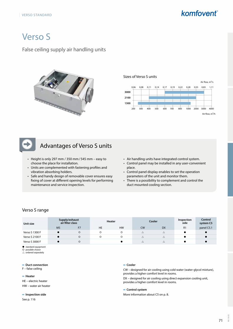
71
VERSO StandaRd
KK-1
8-03
Verso S
200 300 400 500 600 700 800 1000 2000 3000 4000
0,06 0,08 0,11 0,14 0,17 0,19 0,22 0,28 0,55 0,83 1,11
3000
2100
1300
Duct connectionF – false ceiling
Heater
HE–electricheater
HW–waterairheater
Inspection side
See p. 116
False ceiling supply air handling units
Verso S range
Cooler
CW – designed for air cooling using cold water (water-glycol mixture), provides a higher comfort level in rooms.
DX – designed for air cooling using direct expansion cooling unit, provides a higher comfort level in rooms.
Control system
More information about C5 on p. 8.
� standard equipment� possible choice ordered separately
Unit sizeSupply/exhaust
air filter class Heater Cooler Inspection side
Control system C5
M5 F7 HE HW CW DX R1 panel C5.1
Verso S 1300 F � � � � � �
Verso S 2100 F � � � � � �
Verso S 3000 F � � � � �
Sizes of Verso S units
Air flow, m³/h
Air flow, m³/s
Advantages of Verso S units
• Heightisonly297mm/350mm/545mm–easytochoose the place for installation.
• Units are complemented with fastening profiles and vib ration absorbing holders.
• Safe and handy design of removable cover ensures easy fi xing of cover at different opening levels for perfor ming maintenance and service inspection.
• Air handling units have integrated control system.• Control panel may be installed in any user-convenient
place.• Control panel display enables to set the operation
para meters of the unit and monitor them.• There is a possibility to complement and control the
duct mounted cooling section.
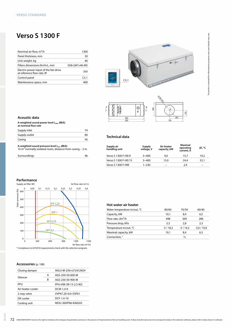
72
VERSO StandaRd
KK-1
8-03
74
80
56
46
1300
50
46
558×287×46-M5
350
C5.1
400
VersoS1300F-HE/9 3~400 9,0 15,7 19,2
VersoS1300F-HE/15 3~400 15,0 24,4 32,1
VersoS1300F-HW 1~230 – 2,9 –
Verso S 1300 F
AGUJ-M-250+LF24/LM24
AGS-250-50-600-M
AGS-250-50-900-M
PPU-HW-3R-15-2.5-W2
DCW-1,4-9
VVP47.20-4,0+SSP61
DCF-1,4-10
MOU-36HFN6-KA8243
C5.1
10,1 8,4 6,5
448 369 286
3,3 2,8 2,3
-5 / 18,2 -5 / 14,2 -5,0 / 10,0
10,1 8,4 6,5
½
0 0,05 0,1 0,15 0,2 0,25 0,3 0,35 0,4
0 300 600 900 1200 1500
600
500
400
300
200
100
0
SFP 1,25
SFP 1
SFP 0,75
SFP 0,5
Verso_S_1300
AA B
350
152
700893925
350
⌀ 250 (2x)
Acoustic dataA-weighted sound power level LwA, dB(A)at nominal flow rate
Supply inlet
Supply outlet
Casing
A-weighted sound pressure level LPA, dB(A) 10 m² normally isolated room, distance from casing – 3 m.
Surroundings
Nominal air flow, m³/h
Panel thickness, mm
Unit weight, kg
Filters dimensions B×H×L, mm
Electric power input of the fan drive at reference flow rate, W
Control panel
Maintenance space, mm
Hot water air heaterWater temperature in/out, °C 80/60 70/50 60/40
Capacity, kW
Flow rate, dm³/h
Pressure drop, kPa
Temperature in/out, °C
Maximal capacity, kW
Connection, ”
The
phot
o is
inte
nded
for i
nfor
mat
iona
l pur
pose
s on
ly, e
xact
det
ails
may
var
y.
Technical data
Supply air handling unit
Supply voltage, V
Air heater capacity, kw
Maximal operating current, A
ΔT, °C
Stat
ic p
ress
ure
(Pa)
Air flow rate (m3/h)
Accessories (p. 108)
Closing damper
SilencerA
B
PPU
Air heater-cooler
2-way valve
DX cooler
Cooling unit
UAB KOMFOVENT reserves the right to introduce the changes of parameters and sizes in the process of improvement of the air handling units. If data of performance do not correspond to data in the selection software, please refer to data shown in software.
Air flow rate (m3/s)
PerformanceSupply air filter M5
* Compliance to ErP2018 requirements check with the selection program.
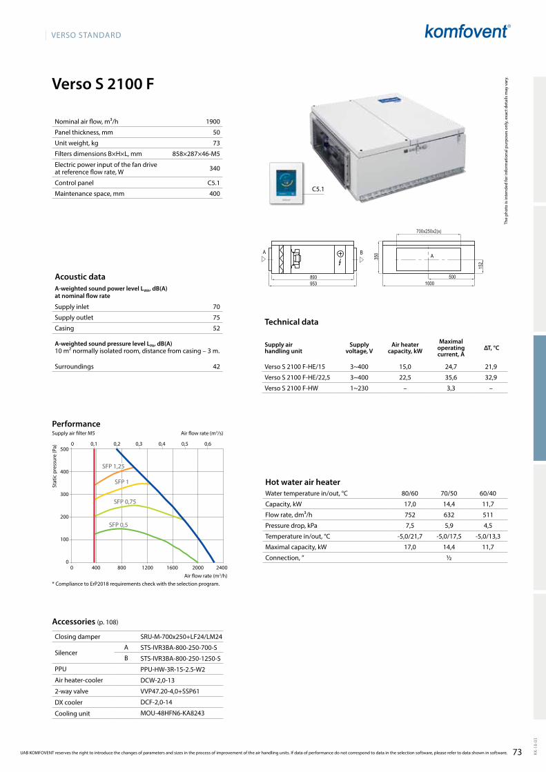
VERSO StandaRd
73 KK-1
8-03
Verso S 2100 F
70
75
52
42
1900
50
73
858×287×46-M5
340
C5.1
400
VersoS2100F-HE/15 3~400 15,0 24,7 21,9
VersoS2100F-HE/22,5 3~400 22,5 35,6 32,9
VersoS2100F-HW 1~230 – 3,3 –
SRU-M-700x250+LF24/LM24
STS-IVR3BA-800-250-700-S
STS-IVR3BA-800-250-1250-S
PPU-HW-3R-15-2.5-W2
DCW-2,0-13
VVP47.20-4,0+SSP61
DCF-2,0-14
MOU-48HFN6-KA8243
C5.1
0 400 800 1200 1600 2000 2400
500
400
300
200
100
0
0 0,1 0,2 0,3 0,4 0,5 0,6
SFP 1,25
SFP 0,75
SFP 0,5
SFP 1
17,0 14,4 11,7
752 632 511
7,5 5,9 4,5
-5,0/21,7 -5,0/17,5 -5,0/13,3
17,0 14,4 11,7
½
Verso_S_2100
AA B
500
152
1000893953
350
700x250x2(x)
Acoustic dataA-weighted sound power level LwA, dB(A)at nominal flow rate
Supply inlet
Supply outlet
Casing
A-weighted sound pressure level LPA, dB(A) 10 m² normally isolated room, distance from casing – 3 m.
Surroundings
Nominal air flow, m³/h
Panel thickness, mm
Unit weight, kg
Filters dimensions B×H×L, mm
Electric power input of the fan drive at reference flow rate, W
Control panel
Maintenance space, mm
Hot water air heaterWater temperature in/out, °C 80/60 70/50 60/40
Capacity, kW
Flow rate, dm³/h
Pressure drop, kPa
Temperature in/out, °C
Maximal capacity, kW
Connection, ”
The
phot
o is
inte
nded
for i
nfor
mat
iona
l pur
pose
s on
ly, e
xact
det
ails
may
var
y.
Technical data
Supply air handling unit
Supply voltage, V
Air heater capacity, kW
Maximal operating current, A
ΔT, °C
Stat
ic p
ress
ure
(Pa)
Air flow rate (m3/h)
Accessories (p. 108)
Closing damper
SilencerA
B
PPU
Air heater-cooler
2-way valve
DX cooler
Cooling unit
UAB KOMFOVENT reserves the right to introduce the changes of parameters and sizes in the process of improvement of the air handling units. If data of performance do not correspond to data in the selection software, please refer to data shown in software.
Air flow rate (m3/s)
PerformanceSupply air filter M5
* Compliance to ErP2018 requirements check with the selection program.
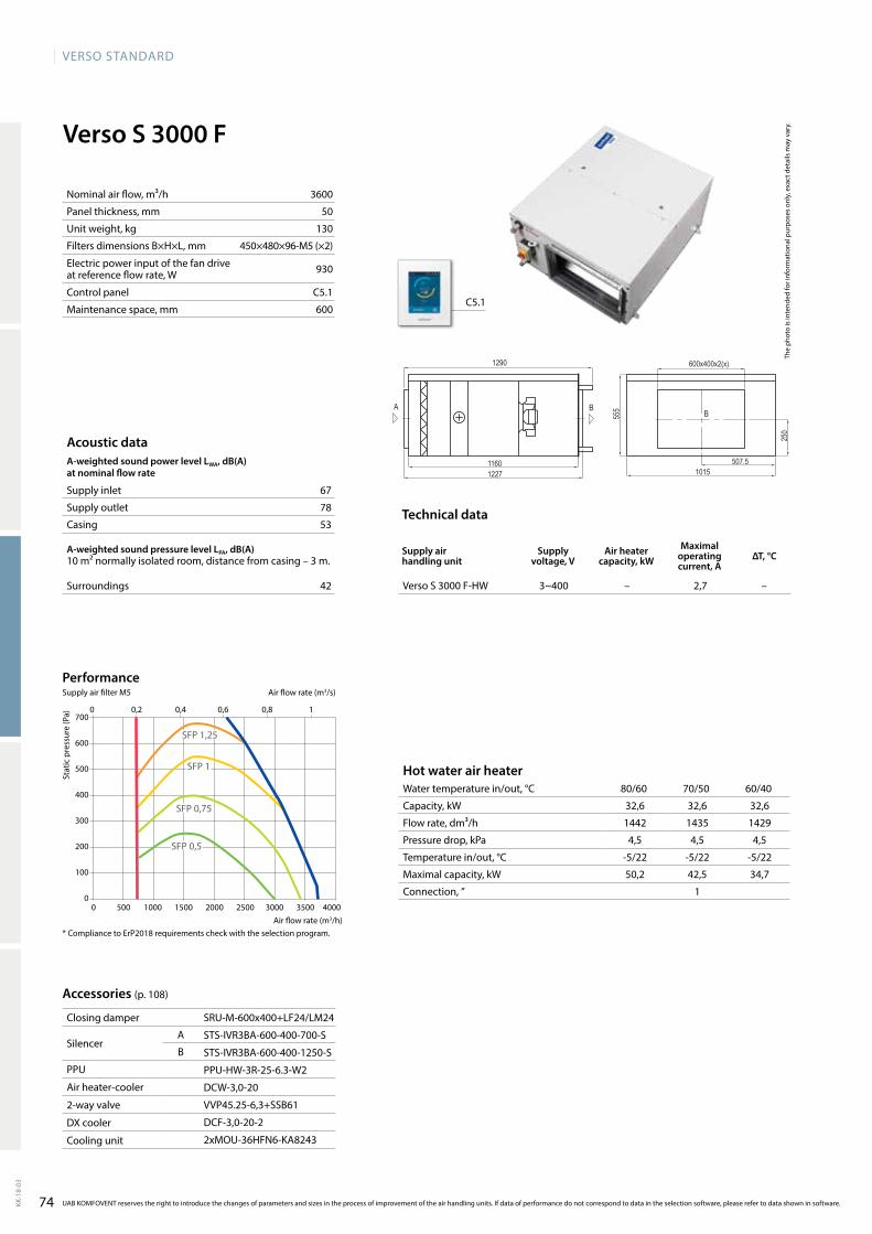
74
VERSO StandaRd
KK-1
8-03
Verso S 3000 F
67
78
53
42
3600
50
130
450×480×96-M5 (×2)
930
C5.1
600
VersoS3000F-HW 3~400 – 2,7 –
SRU-M-600x400+LF24/LM24
STS-IVR3BA-600-400-700-S
STS-IVR3BA-600-400-1250-S
PPU-HW-3R-25-6.3-W2
DCW-3,0-20
VVP45.25-6,3+SSB61
DCF-3,0-20-2
2xMOU-36HFN6-KA8243
C5.1
32,6 32,6 32,6
1442 1435 1429
4,5 4,5 4,5
-5/22 -5/22 -5/22
50,2 42,5 34,7
1
Verso_S_3000
BA B
507.5
250
101511601227
555
600x400x2(x)1290
0 500 1000 1500 2000 2500 3000 3500 4000
700
600
500
400
300
200
100
0
SFP 1,25
SFP 1
SFP 0,75
SFP 0,5
0 0,2 0,4 0,6 0,8 1
Acoustic dataA-weighted sound power level LwA, dB(A)at nominal flow rate
Supply inlet
Supply outlet
Casing
A-weighted sound pressure level LPA, dB(A) 10 m² normally isolated room, distance from casing – 3 m.
Surroundings
Nominal air flow, m³/h
Panel thickness, mm
Unit weight, kg
Filters dimensions B×H×L, mm
Electric power input of the fan drive at reference flow rate, W
Control panel
Maintenance space, mm
Hot water air heaterWater temperature in/out, °C 80/60 70/50 60/40
Capacity, kW
Flow rate, dm³/h
Pressure drop, kPa
Temperature in/out, °C
Maximal capacity, kW
Connection, ”
The
phot
o is
inte
nded
for i
nfor
mat
iona
l pur
pose
s on
ly, e
xact
det
ails
may
var
y.
Technical data
Supply air handling unit
Supply voltage, V
Air heater capacity, kw
Maximal operating current, A
ΔT, °C
Stat
ic p
ress
ure
(Pa)
Air flow rate (m3/h)
Accessories (p. 108)
Closing damper
SilencerA
B
PPU
Air heater-cooler
2-way valve
DX cooler
Cooling unit
UAB KOMFOVENT reserves the right to introduce the changes of parameters and sizes in the process of improvement of the air handling units. If data of performance do not correspond to data in the selection software, please refer to data shown in software.
Air flow rate (m3/s)
PerformanceSupply air filter M5
* Compliance to ErP2018 requirements check with the selection program.
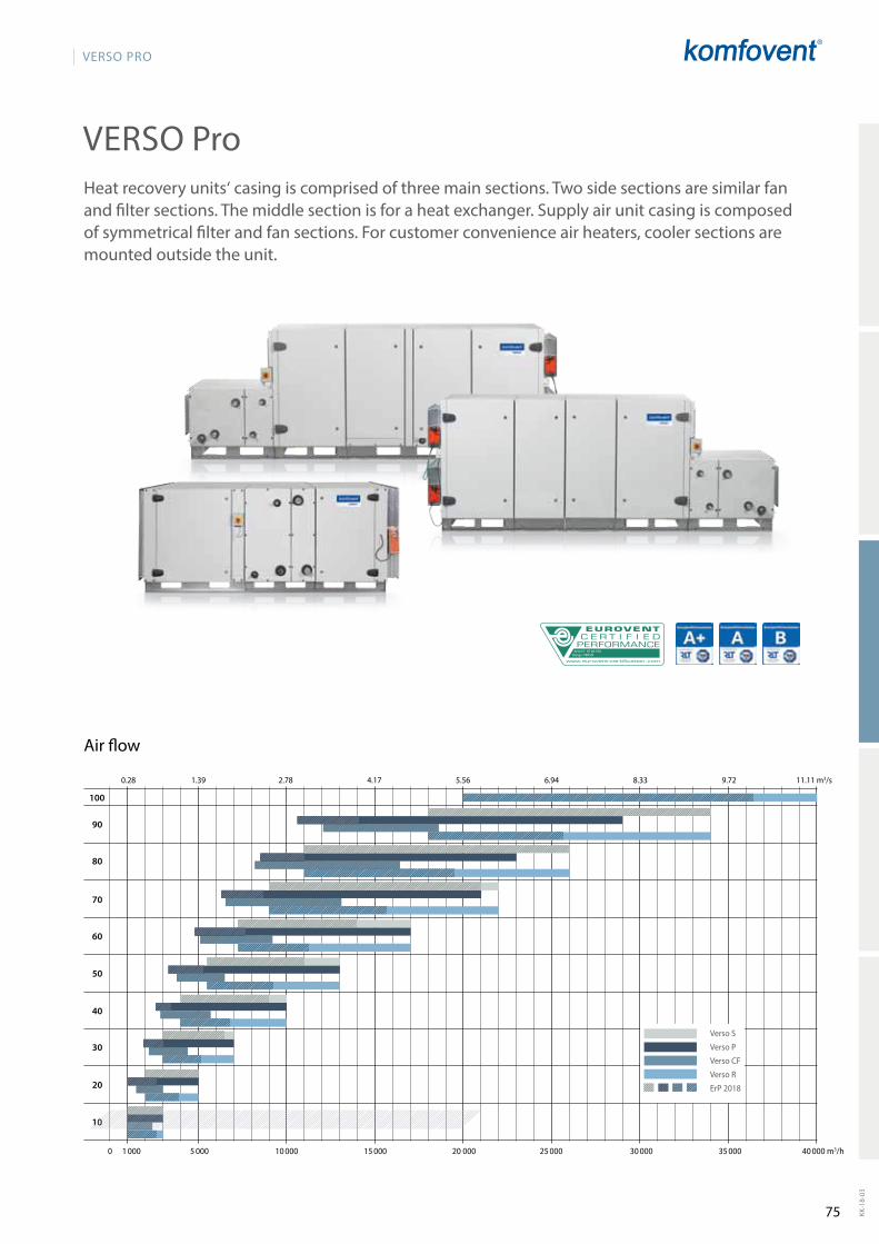
75
VERSO PRO
KK-1
8-03
AHU N˚: 07.09.356Range: VERSO
10
20
30
40
50
60
70
80
90
100
0 1 000 5 000 10 000 15 000 20 000 25 000 30 000 35 000 40 000 m3/h
0.28 1.39 2.78 4.17 5.56 6.94 8.33 9.72 11.11 m3/s
Verso S
Verso P
Verso CF
Verso R
ErP 2018
Heatrecoveryunits‘casingiscomprisedofthreemainsections.Twosidesectionsaresimilarfanand filter sections. The middle section is for a heat exchanger. Supply air unit casing is composed of symmetrical filter and fan sections. For customer convenien ce air heaters, cooler sections are mounted outside the unit.
VERSO Pro
Air flow
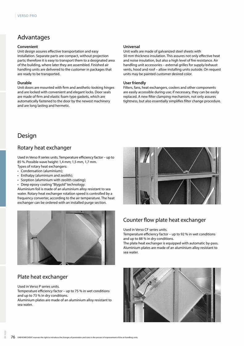
76
VERSO PRO
KK-1
8-03
UAB KOMFOVENT reserves the right to introduce the changes of parameters and sizes in the process of improvement of the air handling units.
ConvenientUnit design assures effective transportation and easy installation. Separate parts are compact, without projection parts;thereforeitiseasytotransportthemtoadesignatedareaof the building, where later they are assembled. Fi nished air handling units are delivered to the customer in packages that are ready to be transported.
DurableUnit doors are mounted with firm and aesthetic-looking hinges and are locked with convenient and elegant locks. Door seals are made of firm and elastic foam type gaskets, which are automatically fastened to the door by the newest machinery and are long lasting and hermetic.
Universal Unit walls are made of galvanized steel sheets with 50 mm thickness insulation. This assures not only effective heat and noise insulation, but also a high level of fire resistance. Air handling unit accessories – external grilles for supply/exhaust vents, hood and roof – allow installing units outside. On request units may be painted customer desired color.
User friendlyFilters, fans, heat exchangers, coolers and other components areeasilyaccessibleduringuse;ifnecessary,theycanbeeasilyreplaced. A new filter clamping mechanism, not only assures tightness, but also essentially simplifies filter change procedure.
Design
Advantages
Counter flow plate heat exchanger
Used in Verso CF series units.Temperature efficiency factor – up to 92 % in wet conditions and up to 88 % in dry conditions.The plate heat exchanger is equipped with automatic by-pass. Aluminium plates are made of an aluminium alloy resistant to sea water.
Plate heat exchanger
Used in Verso P series units.Temperature efficiency factor – up to 75 % in wet conditions and up to 73 % in dry conditions. Aluminium plates are made of an aluminium alloy resistant to sea water.
Rotary heat exchanger
Used in Verso R series units. Temperature efficiency factor – up to 85%.Possiblewaveheight:1,4mm;1,5mm,1,7mm.Types of rotary heat exchangers:• Condensation(aluminium);• Enthalpy(aluminiumandzeolith);• Sorption(aluminiumwithzeolithcoating);• Deepepoxycoating“Blygold”technology.Aluminium foil is made of an aluminium alloy resistant to sea water. Rotary heat exchanger rotation speed is controlled by a frequency converter, according to the air temperature. The heat exchanger can be ordered with an installed purge section.
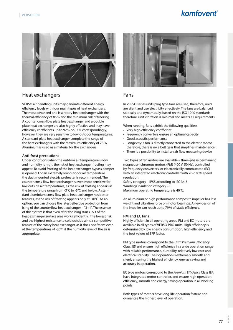
77
VERSO PRO
KK-1
8-03
Fans
In VERSO series units plug type fans are used, therefore, units are silent and use electricity effectively. The fans are balanced staticallyanddynamically,basedontheISO1940standard;therefore, unit vibration is minimal and meets all requirements.
When running, fans exhibit the following qualities:• Very high efficiency coefficient• Frequency converters ensure an optimal capacity• Good acoustic performance• Longevity: a fan is directly connected to the electric motor,
therefore, there is no a belt gear that simplifies maintenance.• There is a possibility to install an air flow measuring device
Two types of fan motors are available – three-phase permanent magnetsynchronousmotors(PM)(400V,50Hz),controlledby frequency converters, or electronically commutated (EC) with an integ rated electronic controller with 20–100% speed regulation.Safety category – IP55 according to IEC 34-5. Windings insulation category – F.Maximum operating temperature is 40°C.
An aluminium or high performance composite impeller has less weight and vibration force on motor bearings. A new design of the impeller can reach up to 79 % of static efficiency.
PM and EC fansHighlyefficientinalloperatingareas,PMandECmotorsareavailable in all types of VERSO PROunits.Highefficiencyisdetermined by low energy consumption, high efficiency and the best values of SFP factor.
PM type motors correspond to the Ultra Premium Efficiency Class IE5 and ensure high efficiency in a wide operation range with reliable performance, durability, relatively low cost and electrical stability. Their operation is extremely smooth and silent, ensuring the highest efficiency, energy saving and accuracy in operation.
EC type motors correspond to the Premium Efficiency Class IE4, have integrated motor controller, and ensure high operation efficiency, smooth and energy saving operation in all working points.
Bothtypesofmotorshavelong-lifeoperationfeatureandguarantee the highest level of operation.
Heatexchangers
VERSO air handling units may generate different energy efficiency levels with four main types of heat exchangers. The most advanced one is a rotary heat exchanger with the thermal efficiency of 85 % and the minimum risk of freezing. A counter cross-flow plate heat exchanger and a double plate heat exchanger are also highly effective and may have efficiency coefficients up to 92 % or 82 % correspondingly, however, they are very sensitive to low outdoor temperatures. A standard plate heat exchanger complete the range of the heat exchangers with the maximum efficiency of 73 %. Aluminium is used as a material for the exchangers.
Anti-frost precautionsUnder conditions when the outdoor air temperature is low and humidity is high, the risk of heat exchanger frosting may appear. To avoid frosting of the heat exchanger bypass damper is opened. For an extremely low outdoor air temperature the duct mounted electric preheater is recommended. The counter cross-flow heat exchanger is even more sensitive for low outside air temperatures, as the risk of frosting appears in the temperature range from -3°C to -5°C and below. A stan-dard aluminium cross-flow plate heat exchanger has better features, as the risk of freezing appears only at -10°C. As an option, you can choose the latest effective protection from icing of the counterflow heat exchanger – "3+1". The essence of this system is that even after the icing starts, 2/3 of the heat exchanger surface area works efficiently. The lo west risk and the highest resistance to cold outside air is a competitive feature of the rotary heat exchanger, as it does not freeze even at the temperatures of -30°C if the humi dity level of the air is appropriate.
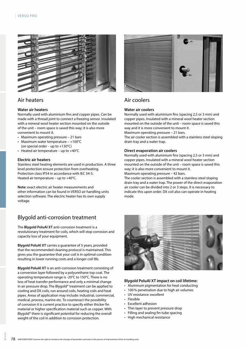
78
VERSO PRO
KK-1
8-03
UAB KOMFOVENT reserves the right to introduce the changes of parameters and sizes in the process of improvement of the air handling units.
Air coolers
Water air coolersNormally used with aluminium fins (spacing 2,5 or 3 mm) and copper pipes. Insulated with a mineral wool heater section mounted on the outside of the unit – room space is saved this way and it is more convenient to mount it. Maximum operating pressure – 21 bars.The air cooler section is assembled with a stainless steel sloping drain tray and a water trap.
Direct evaporation air coolersNormally used with aluminium fins (spacing 2,5 or 3 mm) and copper pipes. Insulated with a mineral wool heater section mounted on the outside of the unit – room space is saved this way;itisalsomoreconvenienttomountit.Maximum operating pressure – 42 bars.The cooler section is assembled with a stainless steel slo ping drain tray and a water trap. The power of the direct evaporation air cooler can be divided into 2 or 3 steps. It is necessary to indicate this upon order. DX coil also can operate in heating mode.
Air heaters
Water air heatersNormally used with aluminium fins and copper pipes. Can be made with a thread joint to connect a freezing sensor. Insulated with a mineral wool heater section mounted on the outside oftheunit–roomspaceissavedthisway;itisalsomoreconvenient to mount it. • Maximum operating pressure – 21 bars• Maximum water temperature – +100°C
(on special order – up to +130°C)• Heatedairtemperature–upto+40°C
Electric air heatersStainless steel heating elements are used in production. A three level protection ensure protection from over heating.Protection class IP54 in accordance with IEC 34-5.Heatedairtemperature–upto+40°C.
Note: exact electric air heater measurements and other information can be found in VERSO air handling units selection software. The electric heater has its own supply voltage.
Blygoldanti-corrosiontreatment
The Blygold PoluAl XT anti-corrosion treatment is a revolutionary treatment for coils, which will stop corrosion and capacity loss of your equipment. Blygold PoluAl XT carries a guarantee of 5 years, provided that the recommended cleaning protocol is maintained. This gives you the guarantee that your coil is in optimal condition resulting in lower running costs and a longer coil life.
Blygold PoluAl XT is an anti-corrosion treatment consisting of a conversion layer followed by a polyurethane top coat. The operating temperature range is -20°C to 150°C. There is no loss of heat transfer performance and only a minimal change inairpressuredrop.TheBlygold®treatmentcanbeappliedtocooling and DX coils, run around coils, heating coils and heat pipes. Areas of application may include: industrial, commercial, medical, process, marine etc. To counteract the possibility of corrosion it is current practice to specify either thicker fin material or higher specification material such as copper. With Blygold®thereissignificantpotentialforreducingtheoverallweight of the coil in addition to corrosion protection.
Blygold PoluAl XT impact on coil lifetime: • Aluminum pigmentation for heat conducting• 100 % penetration due to high air volumes• UV resistance: excellent• Flexible• Excellent adhesion• Thin layer to prevent pressure drop• Filling and sealing fin-tube spacing• Highmechanicalresistance
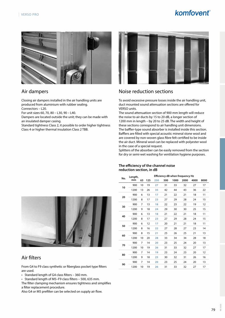
79
VERSO PRO
KK-1
8-03
Air dampers
Closing air dampers installed in the air handling units are produced from aluminium with rubber sealing.Connectors – L20.For unit sizes 60, 70, 80 – L30, 90 – L40.Dampersarelocatedoutsidetheunit;theycanbemadewithan insulated damper casing.Standard tightness Class 2, it possible to order higher tightness Class4orhigherthermalinsulationClass2TBB.
Air filters
From G4 to F9 class synthetic or fiberglass pocket type filters are used.• Standard length of G4 class filters – 360 mm.• Standard length of M5–F9 class filters – 500, 635 mm.The filter clamping mechanism ensures tightness and simp lifies a filter replacement procedure.Also G4 or M5 prefilter can be selected on supply air flow.
Noise reduction sections
To avoid excessive pressure losses inside the air hand ling unit, duct mounted sound attenuation sections are offered for VERSO units.The sound attenuation section of 900 mm length will reduce thenoisetoairductsby15to20dB,alongersectionof1200mminlength–by20to25dB.Thewidthandheightofthese sections correspond to air handling unit dimensions.The baffler-type sound absorber is installed inside this section. Bafflersarefilledwithspecialacousticmineralstonewoolandare covered by non-woven glass fibre felt certified to be inside the air duct. Mineral wool can be replaced with polyester wool in the case of a special request.Splitters of the absorber can be easily removed from the section for dry or semi-wet washing for ventilation hygiene purposes.
63 125 250 500 1000 2000 4000 8000
10900 10 19 27 31 33 32 27 17
1200 13 26 35 42 44 43 36 22
20900 6 13 17 21 22 21 18 11
1200 8 17 23 27 29 28 24 15
30900 7 13 18 22 23 22 19 12
1200 9 18 24 29 30 30 25 15
40900 6 13 18 21 22 21 18 11
1200 8 17 23 27 29 28 24 15
50900 6 12 17 20 21 21 18 11
1200 8 16 22 27 28 27 23 14
60900 8 15 21 25 26 25 21 13
1200 10 20 28 33 34 34 28 18
70900 7 14 20 23 25 24 20 13
1200 10 19 26 31 33 32 27 17
80900 7 14 19 23 24 23 20 12
1200 9 18 25 30 32 31 26 16
90900 7 14 20 23 25 24 20 13
1200 10 19 26 31 33 32 27 17
The efficiency of the channel noise reduction section, in dB
No. Length, mm
Efficiency dB when frequency Hz
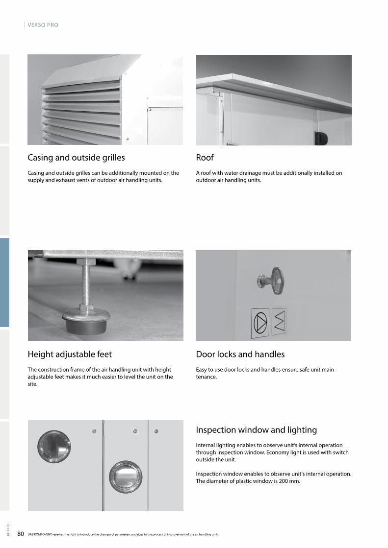
80
VERSO PRO
KK-1
8-03
UAB KOMFOVENT reserves the right to introduce the changes of parameters and sizes in the process of improvement of the air handling units.
Casing and outside grilles
Casing and outside grilles can be additionally mounted on the supply and exhaust vents of outdoor air handling units.
Roof
A roof with water drainage must be additionally installed on outdoor air handling units.
Heightadjustablefeet
The construction frame of the air handling unit with height adjustable feet makes it much easier to level the unit on the site.
Inspection window and lighting
Internallightingenablestoobserveunit‘sinternaloperationthrough inspection window. Economy light is used with switch outside the unit.
Inspectionwindowenablestoobserveunit‘sinternaloperation.The diameter of plastic window is 200 mm.
Door locks and handles
Easy to use door locks and handles ensure safe unit main-tenance.
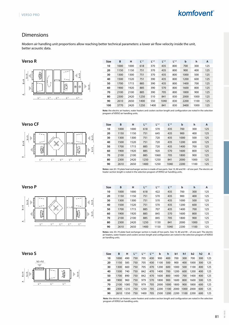
81
VERSO PRO
KK-1
8-03
Verso R
Verso P
L1.1 L1.2 L1.2 L1.1
B×H
A
L1.3
b ×
hb
× h
b ×
h
B H L1.1 L1.2 L1.3 L1.4 b h A10 1000 1000 618 370 435 800 700 300 125
20 1150 1150 751 370 435 800 900 400 125
30 1300 1300 751 370 435 800 1000 500 125
40 1500 1520 751 390 435 800 1200 600 125
50 1700 1715 885 390 435 800 1400 700 125
60 1900 1920 885 390 570 800 1600 800 125
70 2100 2100 885 390 705 800 1800 900 125
80 2300 2420 1250 510 841 830 2000 1000 125
90 2610 2650 1400 550 1040 830 2200 1100 125
100 3770 2420 1250 1400 841 830 3400 1000 125
B H L1.1 L1.2 L1.3 b h A10 1000 1000 618 422 435 700 300 125
20 1150 1150 751 570 435 900 400 125
30 1300 1300 751 570 435 1000 500 125
40 1500 1520 751 570 435 1200 600 125
50 1700 1715 885 707 435 1400 700 125
60 1900 1920 885 845 570 1600 800 125
70 2100 2100 885 845 705 1800 900 125
80 2300 2420 1250 1150 841 2000 1000 125
90 2610 2650 1400 1150 1040 2200 1100 125
Verso CF
L1.1 L1.2 L1.2 L1.1L1.3
b ×
h
b ×
hb
× h
B×H
A
B H L1.1 L1.2 L1.3 b h A10 1000 1000 618 570 435 700 300 125
20 1150 1150 751 645 435 900 400 125
30 1300 1300 751 720 435 1000 500 125
40 1500 1520 751 720 435 1200 600 125
50 1700 1715 885 720 435 1400 700 125
60 1900 1920 885 920 570 1600 800 125
70 2100 2100 885 1060 705 1800 900 125
80 2300 2420 1250 1250 841 2000 1000 125
90 2610 2650 1400 1250 1040 2200 1100 125
Verso S
L1.4 L1.1 L1.2
b2 × h2
B × H
A
b ×
h
b ×
h
B H L1.1 L1.2 L1.4 b h b1 h1 b2 h2 A10 1000 490 750 705 430 900 400 700 300 700 300 125
20 1150 585 750 705 430 1100 500 900 400 1000 300 125
30 1300 660 750 705 470 1200 600 1000 500 1100 400 125
40 1500 740 750 842 470 1400 700 1200 600 1200 400 125
50 1700 890 750 842 470 1600 800 1400 700 1400 400 125
60 1900 960 750 979 570 1800 900 1600 800 1600 500 125
70 2100 1085 750 979 705 2000 1000 1800 900 1800 600 125
80 2300 1235 750 1250 705 2200 1100 2000 1000 2000 600 125
90 2610 1350 750 1400 705 2500 1200 2200 1100 2200 600 125
L1.1 L1.2 L1.3 L1.1 L1.4
b ×
hB×H
A
b ×
h
b ×
h
Dimensions
Modern air handling unit proportions allow reaching better technical parameters: a lower air flow velocity inside the unit, better acoustic data.
Note: the electric air heaters, water heaters and coolers section length and configuration are noted in the selection program of VERSO air handling units.
Notes: size 20÷70 plate heat exchanger section is made of two parts. Size 10, 80 and 90 – of one part. The electric air heaters, water heaters and coolers section length and configuration are noted in the selection program of VERSO air handling units.
Notes: size 20÷70 plate heat exchanger section is made of two parts. Size 10, 80 and 90 – of one part. The electric air heater section length is noted in the selection program of VERSO air handling units.
Note: the electric air heaters, water heaters and coolers section length and configuration are noted in the selection program of VERSO air handling units.
Size
Size
Size
Size
82
RHPVentilation units with heat pump
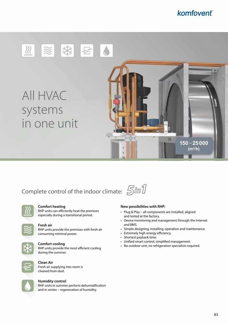
83
150 – 25 000 (m3/h)
All HVAC systems in one unit
Complete control of the indoor climate:
Comfort heatingRHP units can efficiently heat the premises especially during a transitional period.
Fresh airRHP units provide the premises with fresh air consuming minimal power.
Comfort coolingRHP units provide the most efficient cooling during the summer.
Clean AirFresh air supplying into room is cleaned from dust.
Humidity controlRHP units in summer perform dehumidification and in winter – regeneration of humidity.
New possibilities with RHP:• Plug&Play–allcomponentsareinstalled,aligned
and tested at the factory.• DevicemonitoringandmanagementthroughtheInternet
and BMS.• Simpledesigning,installing,operationandmaintenance.• Extremelyhighenergyefficiency.• Shortestpaybacktime.• Unifiedsmartcontrol,simplifiedmanagement.• Nooutdoorunit,norefrigerationspecialistsrequired.
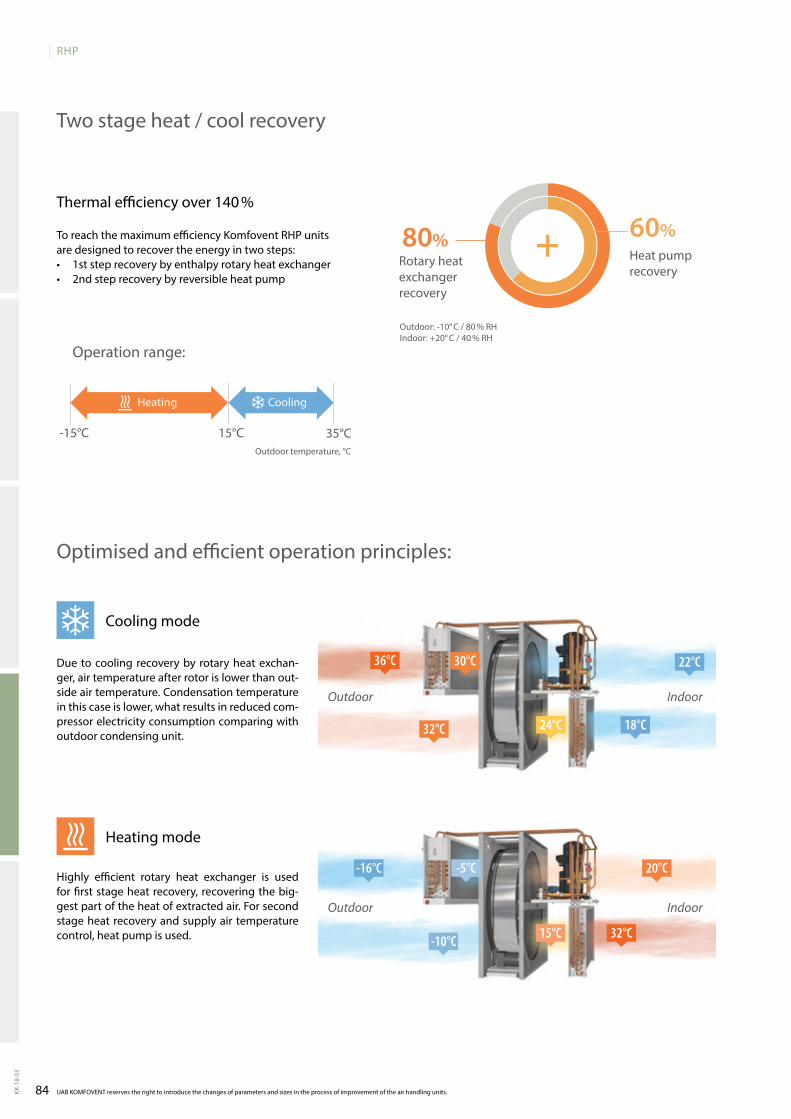
84
RHP
KK-1
8-03
22°C
18°C24°C
36°C
32°C
30°C
-16°C
-10°C
-5°C 20°C
32°C15°C
80% 60%
-15°C 15°C 35°C
UAB KOMFOVENT reserves the right to introduce the changes of parameters and sizes in the process of improvement of the air handling units.
Two stage heat / cool recovery
Due to cooling recovery by rotary heat exchan-ger, air temperature after rotor is lower than out-side air temperature. Condensation temperature in this case is lower, what results in reduced com-pressor electricity consumption comparing with outdoor condensing unit.
Cooling mode
Highly efficient rotary heat exchanger is used for first stage heat recovery, recovering the big-gest part of the heat of extracted air. For second stage heat recovery and supply air temperature control, heat pump is used.
Heating mode
Optimised and efficient operation principles:
Thermal efficiency over 140 %
Outdoortemperature,°C
Operation range:
To reach the maximum efficiency Komfovent RHP units are designed to recover the energy in two steps:• 1ststeprecoverybyenthalpyrotaryheatexchanger• 2ndsteprecoverybyreversibleheatpump
Rotary heat exchanger recovery
Heat pump recovery
Outdoor: -10° C / 80 % RH Indoor: +20° C / 40 % RH
IndoorOutdoor
IndoorOutdoor
Heating Cooling
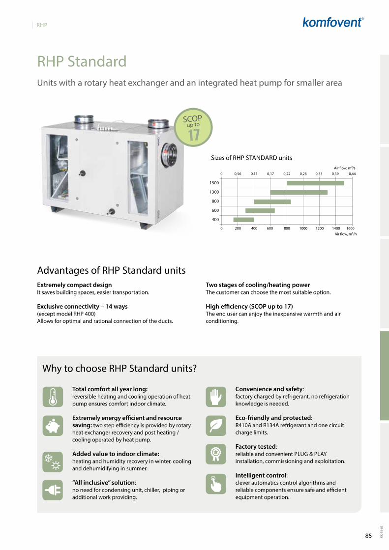
85
RHP
KK-1
8-03
0 200 400 600 800 1000 1200 1400 1600
0 0,56 0,11 0,17 0,22 0,28 0,33 0,39 0,44
1500
1300
800
600
400
RHP Standard
17SCOP
Sizes of RHPStaNDaRD unitsairflow,m³/s
airflow,m³/h
Unitswitharotaryheatexchangerandanintegratedheatpumpforsmallerarea
Total comfort all year long: reversible heating and cooling operation of heat pump ensures comfort indoor climate.
Extremely energy efficient and resource saving: two step efficiency is provided by rotary heat exchanger recovery and post heating / cooling operated by heat pump.
Added value to indoor climate: heating and humidity recovery in winter, cooling and dehumidifying in summer.
“All inclusive” solution: no need for condensing unit, chiller, piping or additional work providing.
Why to choose RHP Standard units?
Convenience and safety: factorychargedbyrefrigerant,norefrigerationknowledgeisneeded.
Eco-friendly and protected: R410A and R134A refrigerant and one circuit charge limits.
Factory tested: reliableandconvenientPlUg&Playinstallation,commissioningandexploitation.
Intelligent control: clever automatics control algorithms and reliablecomponentsensuresafeandefficientequipmentoperation.
up to
Extremely compact designItsavesbuildingspaces,easiertransportation.
Exclusive connectivity – 14 ways(exceptmodelRHP400)Allows for optimal and rational connection of the ducts.
Advantages of RHP Standard unitsTwo stages of cooling/heating powerthecustomercanchoosethemostsuitableoption.
High efficiency (SCOP up to 17)theendusercanenjoytheinexpensivewarmthandairconditioning.
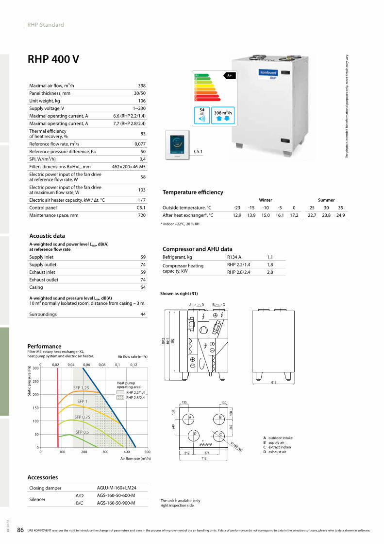
86
RHP Standard
KK-1
8-03
RHP 400 VA+
398 m³/h54
C5.1
R134 A 1,1
RHP 2.2/1.4 1,8
RHP 2.8/2.4 2,8
168
240
168
249
135 130
618
892
1042
212 371
1015
⌀ 160 (4x)
712
RHP 400 V
A B
D C
A D B C
398
30/50
106
1~230
6,6(RHP2.2/1.4)
7,7(RHP2.8/2.4)
83
0,077
50
0,4
462×200×46-M5
58
103
1/7
C5.1
720 12,9 13,9 15,0 16,1 17,2 22,7 23,8 24,9
59
74
59
74
54
44
300
250
200
150
100
50
00 100 200 300 400 500
0 0,02 0,04 0,06 0,08 0,1 0,12
RHP 2.2/1.4RHP 2.8/2.4
SFP1,25
SFP 1
SFP0,75
SFP0,5
The
phot
o is
inte
nded
for i
nfor
mat
iona
l pur
pose
s on
ly, e
xact
det
ails
may
var
y.
Acoustic dataA-weighted sound power level LwA, dB(A)at reference flow rate
Supply inlet
Supply outlet
Exhaust inlet
Exhaust outlet
Casing
A-weighted sound pressure level LPA, dB(A) 10 m² normally isolated room, distance from casing – 3 m.
Surroundings
Maximal air flow, m³/h
Panel thickness, mm
Unit weight, kg
Supply voltage, V
Maximal operating current, A
Maximal operating current, A
Thermal efficiency of heat recovery, %
Reference flow rate, m³/s
Reference pressure difference, Pa
SPI, W/(m³/h)
Filters dimensions B×H×L, mm
Electric power input of the fan drive at reference flow rate, W
Electric power input of the fan drive at maximum flow rate, W
Electric air heater capacity, kW / ∆t, °C
Control panel
Maintenance space, mm
Compressor and AHU dataRefrigerant, kg
Compressor heating capacity, kW
Stat
ic p
ress
ure
(Pa)
Air flow rate (m3/s)
Air flow rate (m3/h)
UAB KOMFOVENT reserves the right to introduce the changes of parameters and sizes in the process of improvement of the air handling units. If data of performance do not correspond to data in the selection software, please refer to data shown in software.
Accessories
Closing damper
SilencerA/D
B/C
Temperature efficiencywinter Summer
Outside temperature, °C -23 -15 -10 -5 0 25 30 35
After heat exchanger*, °C
* indoor +22°C, 20 % RH
PerformanceFilterM5,rotaryheatexchangerXl, heat pump system and electric air heater.
Shown as right (R1)
A outdoorintakeB supply airC extractindoorD exhaustair
Heat pump operating area:
agUJ-M-160+lM24
agS-160-50-600-M
agS-160-50-900-M theunitisavailableonlyright inspection side.
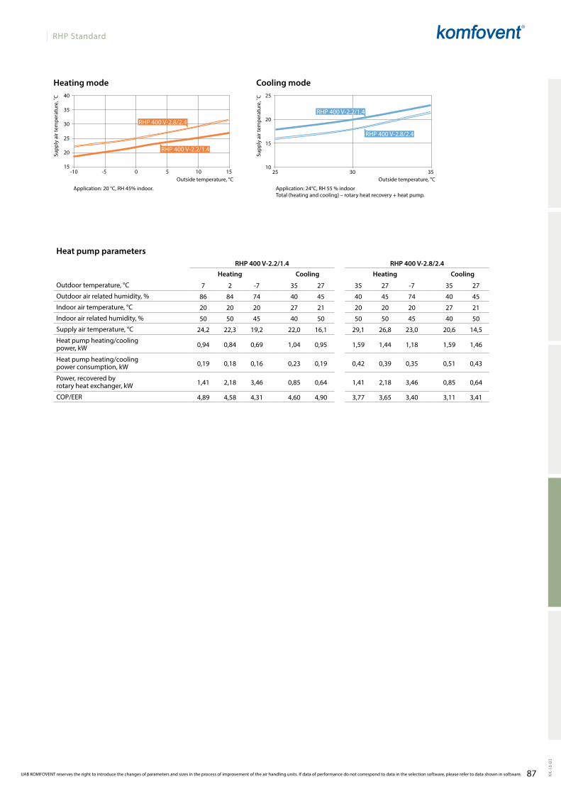
87
RHP Standard
25
20
15
1025 30 35
40
35
30
25
20
15-10 -5 0 5 10 15
KK-1
8-03
RHP 400 V-2.2/1.4
RHP 400 V-2.8/2.4
RHP 400 V-2.2/1.4
RHP 400 V-2.8/2.4
RHP 400 V-2.2/1.4 RHP 400 V-2.8/2.4
7 2 -7 35 27 35 27 -7 35 27
86 84 74 40 45 40 45 74 40 45
20 20 20 27 21 20 20 20 27 21
50 50 45 40 50 50 50 45 40 50
24,2 22,3 19,2 22,0 16,1 29,1 26,8 23,0 20,6 14,5
0,94 0,84 0,69 1,04 0,95 1,59 1,44 1,18 1,59 1,46
0,19 0,18 0,16 0,23 0,19 0,42 0,39 0,35 0,51 0,43
1,41 2,18 3,46 0,85 0,64 1,41 2,18 3,46 0,85 0,64
4,89 4,58 4,31 4,60 4,90 3,77 3,65 3,40 3,11 3,41
Application: 20 °C, RH 45% indoor. Application: 24°C, RH 55 % indoorTotal (heating and cooling) – rotary heat recovery + heat pump.
Outside temperature, °COutside temperature, °C
Cooling modeHeating mode
Supp
ly a
ir te
mpe
ratu
re, ˚
C
Supp
ly a
ir te
mpe
ratu
re, ˚
CHeat pump parameters
Heating Cooling Heating Cooling
Outdoor temperature, °C
Outdoor air related humidity, %
Indoor air temperature, °C
Indoor air related humidity, %
Supply air temperature, °C
Heat pump heating/cooling power, kW
Heat pump heating/cooling power consumption, kW
Power, recovered by rotary heat exchanger, kW
COP/EER
UAB KOMFOVENT reserves the right to introduce the changes of parameters and sizes in the process of improvement of the air handling units. If data of performance do not correspond to data in the selection software, please refer to data shown in software.
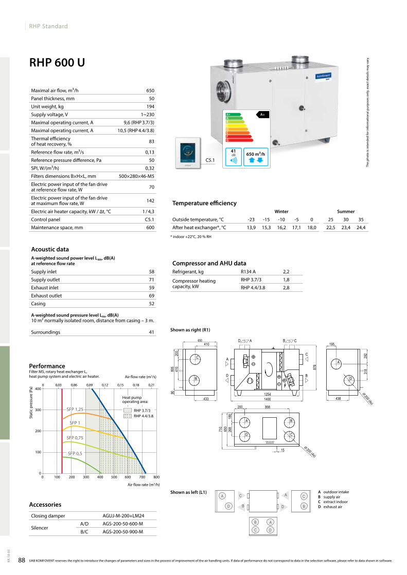
88
RHP Standard
KK-1
8-03
RHP 600 U
58
71
59
69
52
41
650
50
194
1~230
9,6(RHP3.7/3)
10,5(RHP4.4/3.8)
83
0,13
50
0,32
500×280×46-M5
70
142
1/4,3
C5.1
600
A
D
C
BB
C
B
D
A
C
agUJ-M-200+lM24
agS-200-50-600-M
agS-200-50-900-M
A+
650 m³/h41
C5.1
13,9 15,3 16,2 17,1 18,0 22,5 23,4 24,4
A
D
RHP 600 U R1
D
AC
B
B
C
A
D
AD CB
A
D
C
B
12541400
805
410650
410
9020
0
195
318
292
433 438
650
200 866
188
268
878
⌀ 200 (4x)
⌀ 200 (4x)
710
15
R134 A 2,2
RHP3.7/3 1,8
RHP 4.4/3.8 2,8
0 100 200 300 400 500 600 700 800
400
300
200
100
0
RHP3.7/3RHP 4.4/3.8
SFP1,25
SFP 1
SFP0,75
SFP0,5
The
phot
o is
inte
nded
for i
nfor
mat
iona
l pur
pose
s on
ly, e
xact
det
ails
may
var
y.
Acoustic dataA-weighted sound power level LwA, dB(A)at reference flow rate
Supply inlet
Supply outlet
Exhaust inlet
Exhaust outlet
Casing
A-weighted sound pressure level LPA, dB(A) 10 m² normally isolated room, distance from casing – 3 m.
Surroundings
Maximal air flow, m³/h
Panel thickness, mm
Unit weight, kg
Supply voltage, V
Maximal operating current, A
Maximal operating current, A
Thermal efficiency of heat recovery, %
Reference flow rate, m³/s
Reference pressure difference, Pa
SPI, W/(m³/h)
Filters dimensions B×H×L, mm
Electric power input of the fan drive at reference flow rate, W
Electric power input of the fan drive at maximum flow rate, W
Electric air heater capacity, kW / ∆t, °C
Control panel
Maintenance space, mm
Compressor and AHU dataRefrigerant, kg
Compressor heating capacity, kW
Stat
ic p
ress
ure
(Pa)
Air flow rate (m3/s)
Air flow rate (m3/h)
PerformanceFilter M5, rotary heat exchanger L, heat pump system and electric air heater.
UAB KOMFOVENT reserves the right to introduce the changes of parameters and sizes in the process of improvement of the air handling units. If data of performance do not correspond to data in the selection software, please refer to data shown in software.
Accessories
Closing damper
SilencerA/D
B/C
Temperature efficiencywinter Summer
Outside temperature, °C -23 -15 -10 -5 0 25 30 35
After heat exchanger*, °C
* indoor +22°C, 20 % RH
Shown as right (R1)
Shown as left (L1) A outdoorintakeB supply airC extractindoorD exhaustair
Heat pump operating area:
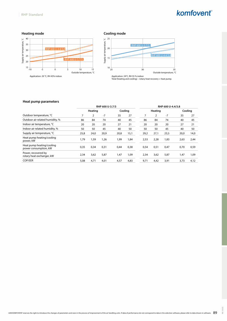
89
RHP Standard
25
20
15
1025 30 35
40
35
30
25
20
15-10 -5 0 5 10 15
KK-1
8-03
RHP 600 U-3.7/3 RHP 600 U-4.4/3.8
7 2 -7 35 27 7 2 -7 35 27
86 84 74 40 45 86 84 74 40 45
20 20 20 27 21 20 20 20 27 21
50 50 45 40 50 50 50 45 40 50
25,8 24,0 20,9 20,8 15,1 29,2 27,1 23,5 20,0 14,0
1,79 1,59 1,26 1,99 1,84 2,53 2,28 1,83 2,63 2,44
0,35 0,34 0,31 0,44 0,38 0,54 0,51 0,47 0,70 0,59
2,34 3,62 5,87 1,47 1,09 2,34 3,62 5,87 1,47 1,09
5,08 4,71 4,01 4,57 4,83 9,71 4,42 3,91 3,73 4,12
RHP600U-4.4/3.8
RHP600U-3.7/3
RHP600U-3.7/3
RHP600U-4.4/3.8
Application: 20 °C, RH 45% indoor. Application: 24°C, RH 55 % indoorTotal (heating and cooling) – rotary heat recovery + heat pump.
Outside temperature, °COutside temperature, °C
Cooling modeHeating mode
Supp
ly a
ir te
mpe
ratu
re, ˚
C
Supp
ly a
ir te
mpe
ratu
re, ˚
CHeat pump parameters
Heating Cooling Heating Cooling
Outdoor temperature, °C
Outdoor air related humidity, %
Indoor air temperature, °C
Indoor air related humidity, %
Supply air temperature, °C
Heat pump heating/cooling power, kW
Heat pump heating/cooling power consumption, kW
Power, recovered by rotary heat exchanger, kW
COP/EER
UAB KOMFOVENT reserves the right to introduce the changes of parameters and sizes in the process of improvement of the air handling units. If data of performance do not correspond to data in the selection software, please refer to data shown in software.
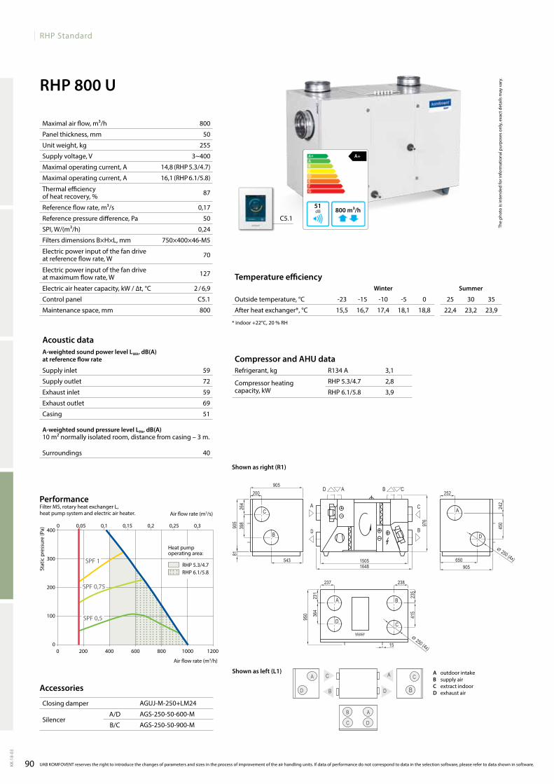
90
RHP Standard
KK-1
8-03
RHP 800 U
A+
800 m³/h51
59
72
59
69
51
40
800
50
255
3~400
14,8(RHP5.3/4.7)
16,1(RHP6.1/5.8)
87
0,17
50
0,24
750×400×46-M5
70
127
2/6,9
C5.1
800
agUJ-M-250+lM24
agS-250-50-600-M
agS-250-50-900-M
C5.1
15,5 16,7 17,4 18,1 18,8 22,4 23,2 23,9
A
D
C
BB
C
B
D
A
C
A
D
RHP 800 U R1
C
B
A
D
A
D
B
C
AD CB
A
D
C
B
15051648
905
200905
398
264
25245
024
2
543 650
237 238
231
364
976
235
415
⌀ 250 (4x)
⌀ 250 (4x)15
950
905
81
R134 A 3,1
RHP5.3/4.7 2,8
RHP 6.1/5.8 3,9
0 200 400 600 800 1000 1200
400
300
200
100
0
0 0,05 0,1 0,15 0,2 0,25 0,3
SPF0,5
SPF0,75
SPF 1RHP5.3/4.7RHP 6.1/5.8
The
phot
o is
inte
nded
for i
nfor
mat
iona
l pur
pose
s on
ly, e
xact
det
ails
may
var
y.
Acoustic dataA-weighted sound power level LwA, dB(A)at reference flow rate
Supply inlet
Supply outlet
Exhaust inlet
Exhaust outlet
Casing
A-weighted sound pressure level LPA, dB(A) 10 m² normally isolated room, distance from casing – 3 m.
Surroundings
Maximal air flow, m³/h
Panel thickness, mm
Unit weight, kg
Supply voltage, V
Maximal operating current, A
Maximal operating current, A
Thermal efficiency of heat recovery, %
Reference flow rate, m³/s
Reference pressure difference, Pa
SPI, W/(m³/h)
Filters dimensions B×H×L, mm
Electric power input of the fan drive at reference flow rate, W
Electric power input of the fan drive at maximum flow rate, W
Electric air heater capacity, kW / ∆t, °C
Control panel
Maintenance space, mm
Compressor and AHU dataRefrigerant, kg
Compressor heating capacity, kW
Stat
ic p
ress
ure
(Pa)
Air flow rate (m3/s)
Air flow rate (m3/h)
PerformanceFilter M5, rotary heat exchanger L, heat pump system and electric air heater.
UAB KOMFOVENT reserves the right to introduce the changes of parameters and sizes in the process of improvement of the air handling units. If data of performance do not correspond to data in the selection software, please refer to data shown in software.
Accessories
Closing damper
SilencerA/D
B/C
Temperature efficiencywinter Summer
Outside temperature, °C -23 -15 -10 -5 0 25 30 35
After heat exchanger*, °C
* indoor +22°C, 20 % RH
Shown as right (R1)
Shown as left (L1) A outdoorintakeB supply airC extractindoorD exhaustair
Heat pump operating area:

91
RHP Standard
25
20
15
1025 30 35
40
35
30
25
20
15-10 -5 0 5 10 15
KK-1
8-03
RHP 800 U-5.3/4.7 RHP 800 U-6.1/5.8
7 2 -7 35 27 7 2 -7 35 27
86 84 74 40 45 86 84 74 40 45
20 20 20 27 21 20 20 20 27 21
50 50 45 40 50 50 50 45 40 50
27,9 26,2 22,9 19,7 14,0 31,1 29 25,5 18,9 13,0
2,63 2,36 1,83 2,84 2,64 3,49 3,12 2,53 3,53 3,32
0,49 0,47 0,44 0,67 0,57 0,77 0,73 0,66 1,04 0,88
3,14 4,99 7,99 1,89 1,40 3,14 4,99 7,99 1,89 1,40
5,34 4,98 4,16 4,23 4,66 4,52 4,29 3,83 3,41 3,79
RHP800U-6.1/5.8
RHP800U-5.3/4.7
RHP800U-5.3/4.7
RHP800U-6.1/5.8
Application: 20 °C, RH 45% indoor. Application: 24°C, RH 55 % indoorTotal (heating and cooling) – rotary heat recovery + heat pump.
Outside temperature, °COutside temperature, °C
Cooling modeHeating mode
Supp
ly a
ir te
mpe
ratu
re, ˚
C
Supp
ly a
ir te
mpe
ratu
re, ˚
CHeat pump parameters
Heating Cooling Heating Cooling
Outdoor temperature, °C
Outdoor air related humidity, %
Indoor air temperature, °C
Indoor air related humidity, %
Supply air temperature, °C
Heat pump heating/cooling power, kW
Heat pump heating/cooling power consumption, kW
Power, recovered by rotary heat exchanger, kW
COP/EER
UAB KOMFOVENT reserves the right to introduce the changes of parameters and sizes in the process of improvement of the air handling units. If data of performance do not correspond to data in the selection software, please refer to data shown in software.
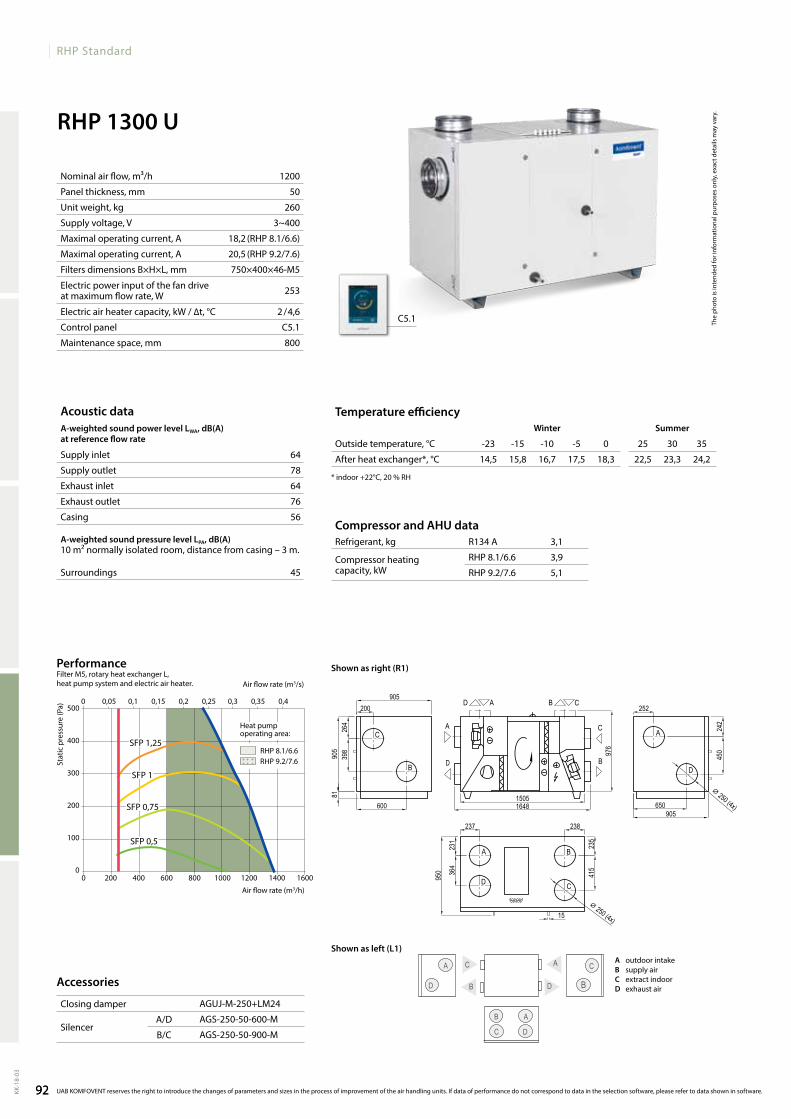
92
RHP Standard
KK-1
8-03
RHP 1300 U
1200
50
260
3~400
18,2(RHP 8.1/6.6)
20,5(RHP9.2/7.6)
750×400×46-M5
253
2/4,6
C5.1
800
64
78
64
76
56
45
R134 A 3,1
RHP 8.1/6.6 3,9
RHP9.2/7.6 5,1
agUJ-M-250+lM24
agS-250-50-600-M
agS-250-50-900-M
C5.1
14,5 15,8 16,7 17,5 18,3 22,5 23,3 24,2
A
D
C
BB
C
B
D
A
C
A
D
RHP 1300 U R1
C
B
A
D
A
D
B
C
AD CB
A
D
C
B
15051648
905
200905
398
264
25245
024
2
600 650
237 238
231
364
976
235
415
⌀ 250 (4x)
⌀ 250 (4x)15
905
950
81
0 200 400 600 800 1000 1200 1400 1600
500
400
300
200
100
0
SFP1,25
SFP 1
SFP0,75
SFP0,5
0 0,05 0,1 0,15 0,2 0,25 0,3 0,35 0,4
RHP 8.1/6.6RHP9.2/7.6
92
The
phot
o is
inte
nded
for i
nfor
mat
iona
l pur
pose
s on
ly, e
xact
det
ails
may
var
y.
Acoustic dataA-weighted sound power level LwA, dB(A)at reference flow rate
Supply inlet
Supply outlet
Exhaust inlet
Exhaust outlet
Casing
A-weighted sound pressure level LPA, dB(A) 10 m² normally isolated room, distance from casing – 3 m.
Surroundings
Compressor and AHU dataRefrigerant, kg
Compressor heating capacity, kW
Staticpressure(Pa)
Air flow rate (m3/s)
Air flow rate (m3/h)
PerformanceFilterM5,rotaryheatexchangerl, heat pump system and electric air heater.
Nominal air flow, m³/h
Panel thickness, mm
Unit weight, kg
Supply voltage, V
Maximal operating current, A
Maximal operating current, A
Filters dimensions B×H×L, mm
Electric power input of the fan drive at maximum flow rate, W
Electric air heater capacity, kW / ∆t, °C
Control panel
Maintenance space, mm
Accessories
Closing damper
SilencerA/D
B/C
Temperature efficiencyWinter Summer
Outside temperature, °C -23 -15 -10 -5 0 25 30 35
After heat exchanger*, °C
* indoor +22°C, 20 % RH
UAB KOMFOVENT reserves the right to introduce the changes of parameters and sizes in the process of improvement of the air handling units. If data of performance do not correspond to data in the selection software, please refer to data shown in software.
A outdoorintakeB supply airC extractindoorD exhaustair
Shown as right (R1)
Shown as left (L1)
Heat pump operating area:
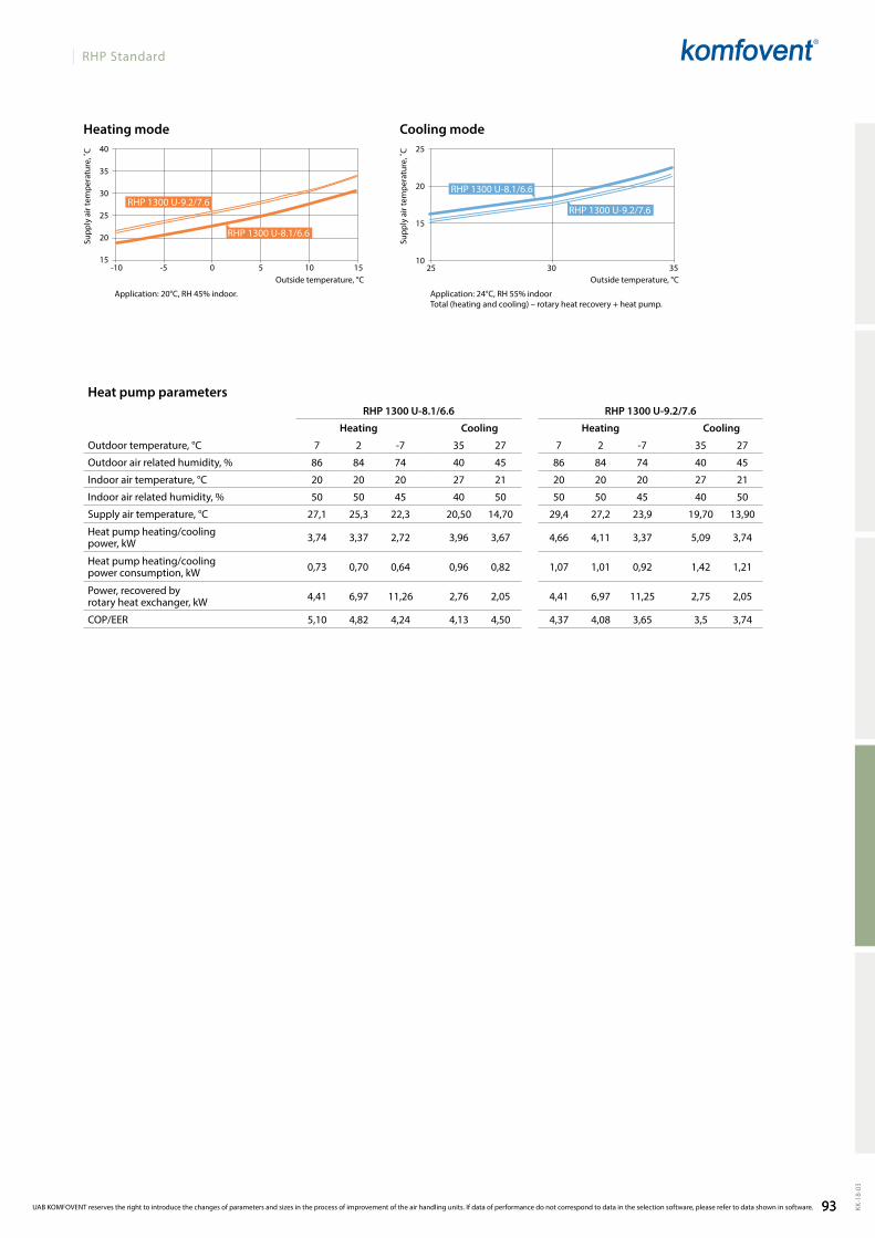
93
RHP Standard
KK-1
8-03
40
35
30
25
20
15
25
20
15
1025 30 35
RHP 1300 U-8.1/6.6 RHP 1300 U-9.2/7.6
7 2 -7 35 27 7 2 -7 35 27
86 84 74 40 45 86 84 74 40 45
20 20 20 27 21 20 20 20 27 21
50 50 45 40 50 50 50 45 40 50
27,1 25,3 22,3 20,50 14,70 29,4 27,2 23,9 19,70 13,90
3,74 3,37 2,72 3,96 3,67 4,66 4,11 3,37 5,09 3,74
0,73 0,70 0,64 0,96 0,82 1,07 1,01 0,92 1,42 1,21
4,41 6,97 11,26 2,76 2,05 4,41 6,97 11,25 2,75 2,05
5,10 4,82 4,24 4,13 4,50 4,37 4,08 3,65 3,5 3,74
RHP1300U-8.1/6.6
RHP1300U-9.2/7.6RHP1300U-9.2/7.6
RHP1300U-8.1/6.6
-10 -5 0 5 10 15
93
Heat pump parameters
Heating Cooling Heating Cooling
Outdoor temperature, °C
Outdoor air related humidity, %
Indoor air temperature, °C
Indoor air related humidity, %
Supply air temperature, °C
Heat pump heating/cooling power, kW
Heat pump heating/cooling power consumption, kW
Power, recovered by rotary heat exchanger, kW
COP/EER
Application: 20°C, RH 45% indoor. Application: 24°C, RH 55% indoorTotal (heating and cooling) – rotary heat recovery + heat pump.
Outside temperature, °C
Cooling modeHeating mode
Supp
ly a
ir te
mpe
ratu
re, ˚
C
Supp
ly a
ir te
mpe
ratu
re, ˚
C
Outside temperature, °C
UAB KOMFOVENT reserves the right to introduce the changes of parameters and sizes in the process of improvement of the air handling units. If data of performance do not correspond to data in the selection software, please refer to data shown in software.
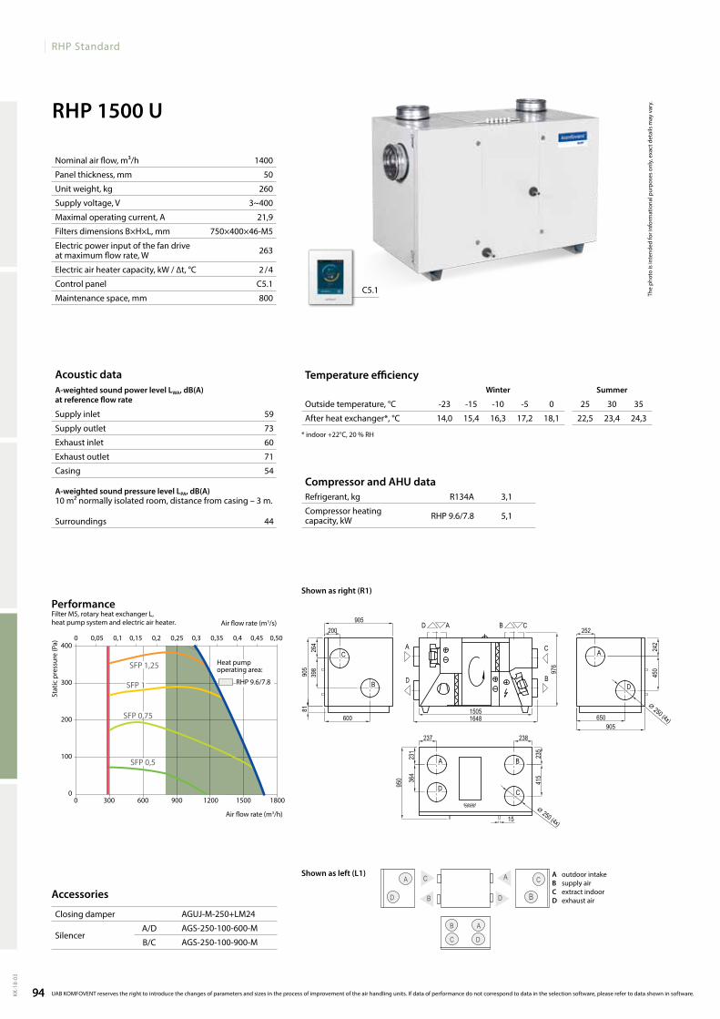
94
RHP Standard
KK-1
8-03
RHP 1500 U
1400
50
260
3~400
21,9
750×400×46-M5
263
2 / 4
C5.1
800
59
73
60
71
54
44
R134A 3,1
RHP9.6/7.8 5,1
agUJ-M-250+lM24
agS-250-100-600-M
agS-250-100-900-M
C5.1
14,0 15,4 16,3 17,2 18,1 22,5 23,4 24,3
A
D
C
BB
C
B
D
A
C
A
D
RHP 1500 U R1
C
B
A
D
A
D
B
C
AD CB
A
D
C
B
15051648
905
200905
398
264
252
450
242
600 650
237 238
231
364
976
235
415
⌀ 250 (4x)
⌀ 250 (4x)
905
15
950
81
0 300 600 900 1200 1500 1800
400
300
200
100
0
0 0,05 0,1 0,15 0,2 0,25 0,3 0,35 0,4 0,45 0,50
SFP1,25
SFP 1
SFP0,75
SFP0,5
RHP9.6/7.8
94
The
phot
o is
inte
nded
for i
nfor
mat
iona
l pur
pose
s on
ly, e
xact
det
ails
may
var
y.
Stat
ic p
ress
ure
(Pa)
Air flow rate (m3/s)
Air flow rate (m3/h)
Acoustic dataA-weighted sound power level LwA, dB(A)at reference flow rate
Supply inlet
Supply outlet
Exhaust inlet
Exhaust outlet
Casing
A-weighted sound pressure level LPA, dB(A) 10 m² normally isolated room, distance from casing – 3 m.
Surroundings
Nominal air flow, m³/h
Panel thickness, mm
Unit weight, kg
Supply voltage, V
Maximal operating current, A
Filters dimensions B×H×L, mm
Electric power input of the fan drive at maximum flow rate, W
Electric air heater capacity, kW / ∆t, °C
Control panel
Maintenance space, mm
PerformanceFilter M5, rotary heat exchanger L, heat pump system and electric air heater.
Accessories
Closing damper
SilencerA/D
B/C
Compressor and AHU dataRefrigerant, kg
Compressor heating capacity, kW
Temperature efficiencywinter Summer
Outside temperature, °C -23 -15 -10 -5 0 25 30 35
After heat exchanger*, °C
* indoor +22°C, 20 % RH
UAB KOMFOVENT reserves the right to introduce the changes of parameters and sizes in the process of improvement of the air handling units. If data of performance do not correspond to data in the selection software, please refer to data shown in software.
Heat pump operating area:
Shown as right (R1)
Shown as left (L1) A outdoorintakeB supply airC extractindoorD exhaustair
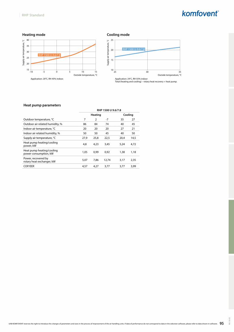
95
RHP Standard
KK-1
8-03
40
35
30
25
20
15
25
20
15
1025 30 35
RHP 1500 U 9.6/7.8
7 2 -7 35 27
86 84 74 40 45
20 20 20 27 21
50 50 45 40 50
27,9 25,8 22,5 20,4 14,5
4,8 4,23 3,45 5,24 4,72
1,05 0,99 0,92 1,38 1,18
5,07 7,86 12,74 3,17 2,35
4,57 4,27 3,77 3,77 3,99
RHP1500U-9.6/7.8
RHP1500U-9.6/7.8
-10 -5 0 5 10 15
95
Application: 20°C, RH 45% indoor. Application: 24°C, RH 55% indoorTotal (heating and cooling) – rotary heat recovery + heat pump.
Outside temperature, °COutside temperature, °C
Cooling modeHeating mode
Supp
ly a
ir te
mpe
ratu
re, ˚
C
Supp
ly a
ir te
mpe
ratu
re, ˚
CHeat pump parameters
Heating Cooling
Outdoor temperature, °C
Outdoor air related humidity, %
Indoor air temperature, °C
Indoor air related humidity, %
Supply air temperature, °C
Heat pump heating/cooling power, kW
Heat pump heating/cooling power consumption, kW
Power, recovered by rotary heat exchanger, kW
COP/EER
UAB KOMFOVENT reserves the right to introduce the changes of parameters and sizes in the process of improvement of the air handling units. If data of performance do not correspond to data in the selection software, please refer to data shown in software.
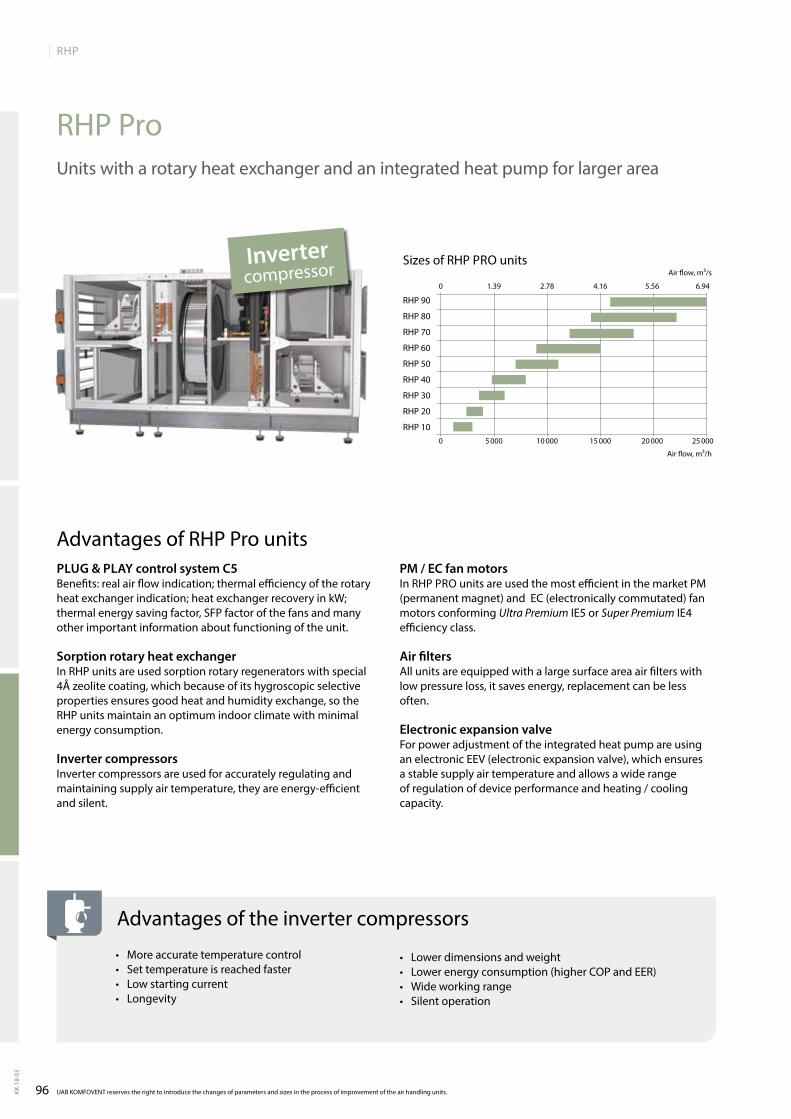
96
RHP
KK-1
8-03
0 5 000 10 000 15 000 20 000 25 000
0 1.39 2.78 4.16 5.56 6.94
RHP90
RHP 80
RHP70
RHP 60
RHP 50
RHP 40
RHP 30
RHP 20
RHP 10
UAB KOMFOVENT reserves the right to introduce the changes of parameters and sizes in the process of improvement of the air handling units.
RHP ProUnitswitharotaryheatexchangerandanintegratedheatpumpforlargerarea
Sizes of RHP PRO unitsairflow,m³/s
airflow,m³/h
PLUg & PLAy control system C5Benefits: real air flow indication; thermal efficiency of the rotary heatexchangerindication;heatexchangerrecoveryinkW;thermalenergysavingfactor,SFPfactorofthefansandmanyotherimportantinformationaboutfunctioningoftheunit.
Sorption rotary heat exchangerInRHPunitsareusedsorptionrotaryregeneratorswithspecial4Åzeolitecoating,whichbecauseofitshygroscopicselectivepropertiesensuresgoodheatandhumidityexchange,sotheRHP units maintain an optimum indoor climate with minimal energy consumption.
Inverter compressors Invertercompressorsareusedforaccuratelyregulatingandmaintainingsupplyairtemperature,theyareenergy-efficient and silent.
Advantages of RHP Pro unitsPM / EC fan motorsInRHPPROunitsareusedthemostefficientinthemarketPM(permanentmagnet)andEC(electronicallycommutated)fanmotors conforming Ultra PremiumIE5orSuper PremiumIE4efficiency class.
Air filtersallunitsareequippedwithalargesurfaceareaairfilterswithlowpressureloss,itsavesenergy,replacementcanbelessoften.
Electronic expansion valve For power adjustment of the integrated heat pump are using anelectronicEEV(electronicexpansionvalve),whichensuresastablesupplyairtemperatureandallowsawiderangeof regulation of device performance and heating / cooling capacity.
• More accurate temperature control• Set temperature is reached faster• Low starting current• Longevity
Advantages of the inverter compressors
• Lower dimensions and weight • lowerenergyconsumption(higherCOPandEER)• Wideworkingrange• Silent operation
Inverter compressor
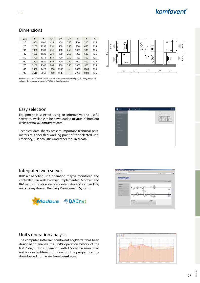
97
RHP
KK-1
8-03
L1.1 L1.2L1.3 L1.3 L1.1
b×h
B ×
HA
b×h
b×h
EasyselectionEquipment is selected using an informative and usefulsoftware,availabletobedownloadedtoyourPCfromourwebsite:www.komfovent.com.
Technical data sheets present important technical para-metersataspecifiedworkingpointoftheselectedunit:efficiency,SFP,acousticsandotherrequireddata.
IntegratedwebserverRHP air handling unit operationmaybemonitored andcontrolled via web browser. ImplementedModbus andBACnet protocols allow easy integration of air handling units to any desired Building Management Systems.
Unit’soperationanalysisthecomputersoftware“KomfoventlogPlotter”hasbeendesigned to analyze the unit’s operation history of thelast 7 days. Unit’s operation with C5 can bemonitorednotonly in real-time fromnowon.theprogramcanbedownloaded from www.komfovent.com.
B H L1.1 L1.2 L1.3 b h A10 1000 1000 618 900 250 700 300 125
20 1150 1150 751 900 250 900 400 125
30 1300 1300 751 900 250 1000 500 125
40 1500 1520 751 900 250 1200 600 125
50 1700 1715 885 900 250 1400 700 125
60 1900 1920 885 900 250 1600 800 125
70 2100 2100 885 900 250 1800 900 125
80 2300 2420 1250 1500 – 2000 1000 125
90 2610 2650 1400 1500 – 2200 1100 125
Note:theelectricairheaters,waterheatersandcoolerssectionlengthandconfigurationarenotedintheselectionprogramofVERSOairhandlingunits.
Size
Dimensions
98
KLASIKNon residential ventilation units
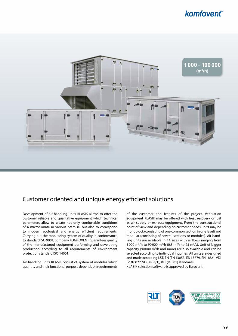
9999
Range: KLASIKAHU No: 16.03.003
1 000 – 100 000
(m3/h)
Development of air handling units KLASIK allows to offer the customer reliable and qualitative equipment which technical parameters allow to create not only comfor table conditions of a microclimate in various premise, but also to corres pond to modern ecological and energy efficient requirements. Carrying out the monitoring system of quality in conformance to standard ISO 9001, company KOMFOVENT guarantees quality of the manufactured equipment performing and developing production according to all requirements of environment protection standard ISO 14001.
Air handling units KLASIK consist of system of modules which quantity and their functional purpose depends on requirements
of the customer and features of the pro ject. Ventilation equipment KLASIK may be offered with heat recovery or just as air supply or exhaust equipment. From the constructional point of view and depending on customer needs units may be monoblock (consis ting of one common section in one level) and modular (consisting of several sections or modules). Air handling units are available in 14 sizes with airflows ranging from 1 000 m3/h to 90 000 m3/h (0,3 m3/s to 25 m3/s). Unit of bigger capa city (90 000 m3/h and more) are also available and can be selected according to individual inquiries. All units are designed and made according LST, EN (EN 13053, EN 13779, EN 1886), VDI (VDI 6022, VDI 3803/1), RLT (RLT 01) standards. KLASIK selection software is approved by Eurovent.
Customer oriented and unique energy efficient solutions
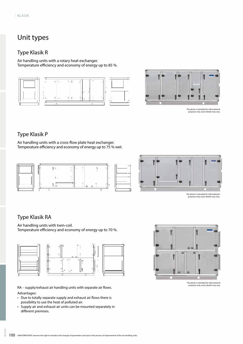
100
KLASIK
KK-1
8-03
UAB KOMFOVENT reserves the right to introduce the changes of parameters and sizes in the process of improvement of the air handling units.
The photo is intended for informational purposes only, exact details may vary.
The photo is intended for informational purposes only, exact details may vary.
Unit types
Type Klasik RAir handling units with a rotary heat exchanger. Temperature efficiency and economy of energy up to 85 %.
Type Klasik PAir handling units with a crossflow plate heat exchanger. Temperature efficiency and economy of energy up to 75 % wet.
Type Klasik RAAir handling units with twincoil. Temperature efficiency and economy of energy up to 70 %.
The photo is intended for informational purposes only, exact details may vary.
RA – supply/exhaust air handling units with separate air flows.
Advantages:• Due to totally separate supply and exhaust air flows there is
possibility to use the heat of polluted air.• Supply air and exhaust air units can be mounted separately in
different premises.
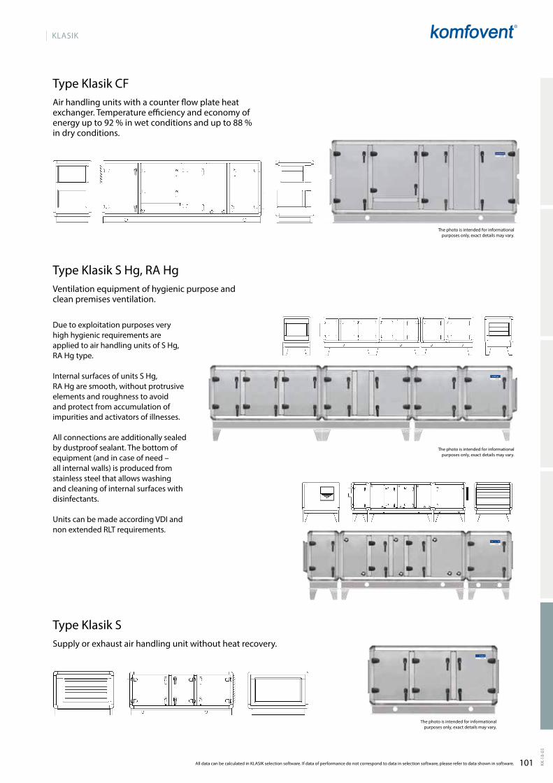
101
KLASIK
KK-1
8-03
All data can be calculated in KLASIK selection software. If data of performance do not correspond to data in selection software, please refer to data shown in software.
The photo is intended for informational purposes only, exact details may vary.
Type Klasik S Hg, RA HgVentilation equipment of hygienic purpose and clean premises ventilation.
Due to exploitation purposes very high hygienic requirements are applied to air handling units of S Hg, RA Hg type.
Internal surfaces of units S Hg, RA Hg are smooth, without protrusive elements and roughness to avoid and protect from accumulation of impurities and activators of illnesses.
All connections are additionally sealed by dustproof sealant. The bottom of equipment (and in case of need – all internal walls) is produced from stainless steel that allows washing and cleaning of internal surfaces with disinfectants.
Units can be made according VDI and non extended RLT requirements.
The photo is intended for informational purposes only, exact details may vary.
Type Klasik CFAir handling units with a counter flow plate heat exchanger. Temperature efficiency and economy of energy up to 92 % in wet conditions and up to 88 % in dry conditions.
Type Klasik SSupply or exhaust air handling unit without heat recovery.
The photo is intended for informational purposes only, exact details may vary.
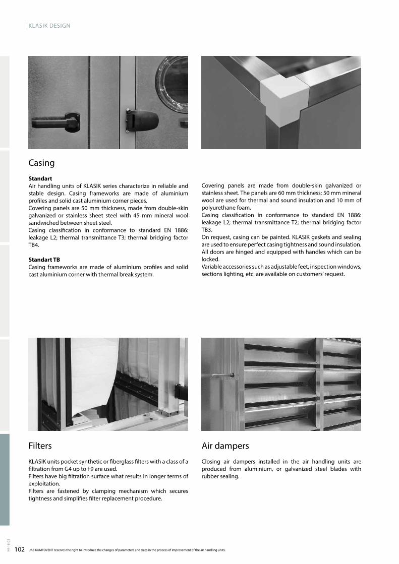
102KK-1
8-03
UAB KOMFOVENT reserves the right to introduce the changes of parameters and sizes in the process of improvement of the air handling units.
KLASIK DESIGN
Filters
KLASIK units pocket synthetic or fiberglass filters with a class of a filtration from G4 up to F9 are used. Filters have big filtration surface what results in longer terms of exploitation. Filters are fastened by clamping mechanism which secures tightness and simplifies filter replacement procedure.
Air dampers
Closing air dampers installed in the air handling units are produced from aluminium, or galvanized steel blades with rubber sealing.
Casing
StandartAir handling units of KLASIK series characterize in reliable and stable design. Casing frameworks are made of aluminium profiles and solid cast aluminium corner pieces.Covering panels are 50 mm thickness, made from doubleskin galvanized or stainless sheet steel with 45 mm mineral wool sandwiched between sheet steel.Casing classification in conformance to standard EN 1886: leakage L2; thermal transmittance T3; thermal bridging factor TB4.
Standart TBCasing frameworks are made of aluminium profiles and solid cast aluminium corner with thermal break system.
Covering panels are made from doubleskin galvanized or stainless sheet. The panels are 60 mm thickness: 50 mm mineral wool are used for thermal and sound insulation and 10 mm of polyurethane foam.Casing classification in conformance to standard EN 1886: leakage L2; thermal transmittance T2; thermal bridging factor TB3.On request, casing can be painted. KLASIK gaskets and sealing are used to ensure perfect casing tightness and sound insulation. All doors are hinged and equipped with handles which can be locked.Variable accessories such as adjustable feet, inspection windows, sections lighting, etc. are available on customers’ request.
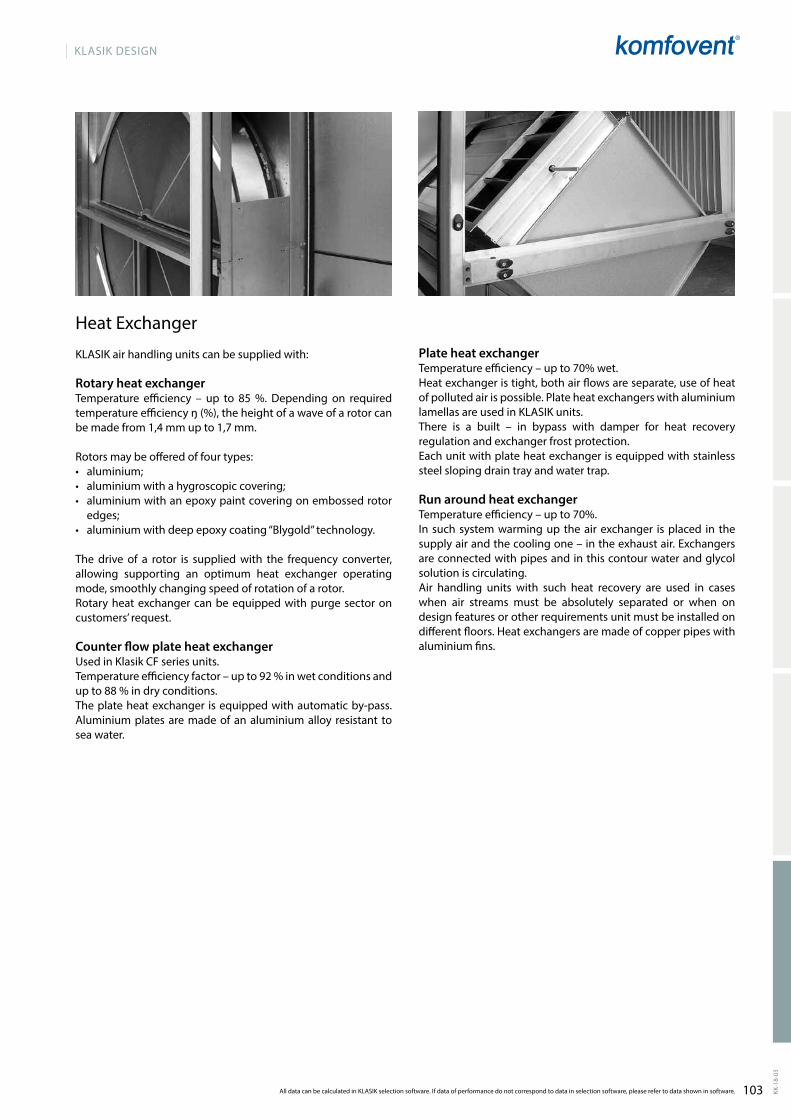
103 KK-1
8-03
All data can be calculated in KLASIK selection software. If data of performance do not correspond to data in selection software, please refer to data shown in software.
KLASIK DESIGN
Heat Exchanger
KLASIK air handling units can be supplied with:
Rotary heat exchanger Temperature efficiency – up to 85 %. Depending on required temperature efficiency ŋ (%), the height of a wave of a rotor can be made from 1,4 mm up to 1,7 mm.
Rotors may be offered of four types:• aluminium; • aluminium with a hygroscopic covering; • aluminium with an epoxy paint covering on embossed rotor
edges;• aluminium with deep epoxy coating “Blygold” techno logy.
The drive of a rotor is supplied with the frequency converter, allowing supporting an optimum heat exchanger operating mode, smoothly changing speed of rotation of a rotor. Rotary heat exchanger can be equipped with purge sector on customers’ request.
Counter flow plate heat exchanger Used in Klasik CF series units.Temperature efficiency factor – up to 92 % in wet conditions and up to 88 % in dry conditions.The plate heat exchanger is equipped with automatic bypass. Aluminium plates are made of an aluminium alloy resistant to sea water.
Plate heat exchangerTemperature efficiency – up to 70% wet. Heat exchanger is tight, both air flows are separate, use of heat of polluted air is possible. Plate heat exchangers with aluminium lamellas are used in KLASIK units. There is a built – in bypass with damper for heat recovery regulation and exchanger frost protection.Each unit with plate heat exchanger is equipped with stainless steel sloping drain tray and water trap.
Run around heat exchangerTemperature efficiency – up to 70%.In such system warming up the air exchanger is placed in the supply air and the cooling one – in the exhaust air. Exchangers are connected with pipes and in this contour water and glycol solution is circulating. Air handling units with such heat recovery are used in cases when air streams must be absolutely separated or when on design features or other requirements unit must be installed on different floors. Heat exchangers are made of copper pipes with aluminium fins.
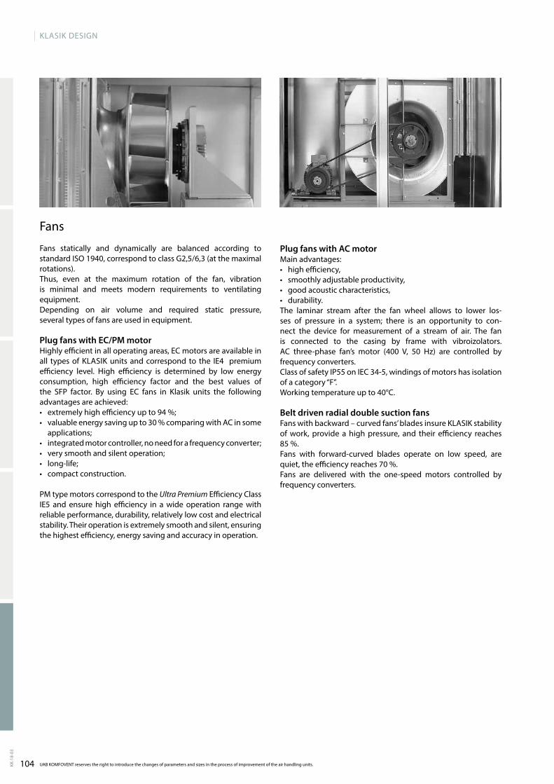
104KK-1
8-03
UAB KOMFOVENT reserves the right to introduce the changes of parameters and sizes in the process of improvement of the air handling units.
KLASIK DESIGN
Fans
Fans statically and dynamically are balanced according to standard ISO 1940, correspond to class G2,5/6,3 (at the maximal rotations).Thus, even at the maximum rotation of the fan, vibration is minimal and meets modern requirements to ventilating equipment. Depending on air volume and required static pressure, several types of fans are used in equipment.
Plug fans with EC/PM motorHighly efficient in all operating areas, EC motors are avai lable in all types of KLASIK units and correspond to the IE4 premium efficiency level. High efficiency is determined by low energy consumption, high efficiency factor and the best values of the SFP factor. By using EC fans in Klasik units the following advantages are achieved:• extremely high efficiency up to 94 %;• valuable energy saving up to 30 % comparing with AC in some
applications;• integrated motor controller, no need for a frequency converter;• very smooth and silent operation;• longlife;• compact construction.
PM type motors correspond to the Ultra Premium Efficiency Class IE5 and ensure high efficiency in a wide operation range with reliable performance, durability, relatively low cost and electrical stability. Their operation is extremely smooth and silent, ensuring the highest efficiency, energy saving and accuracy in operation.
Plug fans with AC motorMain advantages: • high efficiency, • smoothly adjustable productivity, • good acoustic characteristics,• durability. The laminar stream after the fan wheel allows to lower losses of pressure in a system; there is an opportunity to connect the device for measurement of a stream of air. The fan is connected to the casing by frame with vibroizolators. AC threephase fan’s motor (400 V, 50 Hz) are controlled by frequency converters. Class of safety IP55 on IEC 345, windings of motors has isolation of a category “F”. Working temperature up to 40°C.
Belt driven radial double suction fansFans with backward – curved fans’ blades insure KLASIK stability of work, provide a high pressure, and their efficiency reaches 85 %.Fans with forwardcurved blades operate on low speed, are quiet, the efficiency reaches 70 %.Fans are delivered with the onespeed motors controlled by frequency converters.
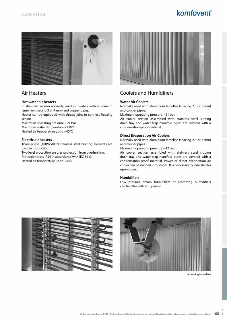
105 KK-1
8-03
All data can be calculated in KLASIK selection software. If data of performance do not correspond to data in selection software, please refer to data shown in software.
KLASIK DESIGN
Atomizing humidifier
Air Heaters
Hot water air heaters In standard version normally used air heaters with alumi nium lamellae (spacing 3 or 4 mm) and copper pipes. Heater can be equipped with thread joint to connect free zing sensor.Maximum operating pressure – 21 bar.Maximum water temperature +130°C. Heated air temperature up to +40°C.
Electric air heaters Threephase (400 V/50 Hz) stainless steel heating elements are used in production.Two level protection ensures protection from overhea ting.Protection class IP54 in accordance with IEC 345.Heated air temperature up to +40°C.
Coolers and Humidifiers
Water Air CoolersNormally used with aluminium lamellae (spacing 2,5 or 3 mm) and copper pipes.Maximum operating pressure – 21 bar.Air cooler section assembled with stainless steel sloping drain tray and water trap manifold pipes are covered with a condensationproof material.
Direct Evaporation Air Coolers Normally used with aluminium lamellae (spacing 2,5 or 3 mm) and copper pipes.Maximum operating pressure – 42 bar.Air cooler section assembled with stainless steel sloping drain tray and water trap manifold pipes are covered with a condensationproof material. Power of direct evaporation air cooler can be divided into stages. It is necessary to indicate this upon order.
HumidifiersLow pressure steam humidifiers or atomizing humidifiers can be offer with equipment.
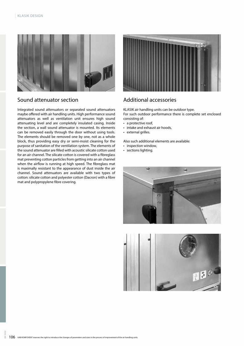
106KK-1
8-03
UAB KOMFOVENT reserves the right to introduce the changes of parameters and sizes in the process of improvement of the air handling units.
KLASIK DESIGN
Sound attenuator section
Integrated sound attenuators or separated sound attenuators maybe offered with air handling units. High performance sound attenuators as well as ventilation unit ensures high sound attenuating level and are completely insulated casing. Inside the section, a wall sound attenuator is mounted. Its elements can be removed easi ly through the door without using tools. The elements should be removed one by one, not as a whole block, thus providing easy dry or semimoist cleaning for the purpose of sanitation of the ventilation system. The elements of the sound attenuator are filled with acoustic silicate cotton used for an air channel. The silicate cotton is covered with a fibreglass mat preventing cotton particles from getting into an air channel when the airflow is running at high speed. The fibreglass mat is maximally resistant to the appearance of dust inside the air channel. Sound attenuators are avai lable with two types of cotton: silicate cotton and polyester cotton (Dacron) with a fibre mat and polypropylene fibre covering.
Additional accessories
KLASIK air handling units can be outdoor type. For such outdoor performance there is complete set enclo sed consisting of: • a protective roof,• intake and exhaust air hoods,• external grilles.
Also such additional elements are available:• inspection window,• sections lighting.
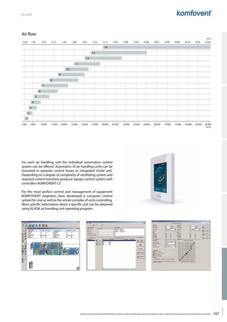
107
KLASIK
KK-1
8-03
1 000 5 000 10 000 15 000 20 000 40 000 45 000 55 000 60 000 65 000 70 000 75 000 80 000 85 000 90 00050 00025 000 30 000 35 000
0.28 1.39 2.78 4.17 5.56 6.94 8.33 9.72 11.11 12.50 13.89 15.29 16.68 18.07 19.46 20.85 22.24 23.63 25.02
2
1
3
4
5
6
7
8
9
10
12
11
13
14
m3/h
m3/s
All data can be calculated in KLASIK selection software. If data of performance do not correspond to data in selection software, please refer to data shown in software.
For each air handling unit the individual automation control system can be offered. Automatics of air handling units can be mounted in separate control boxes or integrated inside unit. Depending on a degree of com p lexity of ventila ting system and required control func tions producer equips control system with controllers KOMFOVENT C5.
For the most perfect control and management of equipment KOMFOVENT engineers have developed a computer control system for one as well as the whole complex of units controlling. More specific information about a specific unit can be obtained using KLASIK air handling unit opera ting program.
Air flow
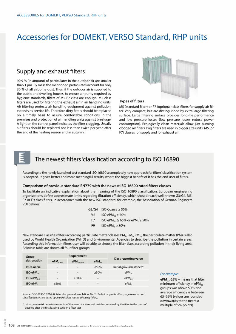
108KK-1
8-03
ACCESSORIES for DOmEkt, VERSO Standard, RHP units
UAB kOmFOVENt reserves the right to introduce the changes of parameters and sizes in the process of improvement of the air handling units.
Accessories for Domekt, Verso standard, rHP units
supply and exhaust filters99,9 % (in amount) of particulates in the outdoor air are smaller than 1 µm. By mass the mentioned particulates account for only 30 % of all airborne dust. thus, if the outdoor air is supplied to the public and dwelling houses, to ensure air purity required by hygienic standards, filters of m5-F7 class are enough. m5 class filters are used for filtering the exhaust air in air handling units. Air filtering protects air handling equipment against pollution, extends its service life. therefore dirty filters should be replaced on a timely basis to assure comfortable conditions in the premises and protection of air handling units against breaka ge. A light on the control panel indicates the filter clogging. Usually air filters should be replaced not less than twice per year: after the end of the heating season and in autumn.
the newest filters ‘classification according to Iso 16890
According to the newly launched test standard Iso 16890 a completely new approach for filters’ classification system is adopted. It gives better and more meaningful results, where the biggest benefit of it has the end user of filters.
Comparison of previous standard EN779 with the newest ISO 16890 rated filters classesto facilitate an indicative explanation about the meaning of the Iso 16890 classification, european engineering organizations define approximate limits regarding filtration efficiency, which should reach well-known G3/G4, m5, F7 or F9 class filters, in accordance with the new Iso standard: for example, the Association of German engineers VDI defines:
G3/G4 Iso Coarse ≥ 50%
m5 Iso ePm10 ≥ 50%
F7 Iso ePm2,5 ≥ 65% or ePm1 ≥ 50%
F9 Iso ePm1 ≥ 80%
New standard classifies filters according particulate matter classes Pm1, Pm2, Pm10, the particulate matter (Pm) is also used by World Health organization (WHo) and environmental Agencies to describe the pollution in certain areas. According this information filters user will be able to choose the filter class according pollution in their living area. Below in table are shown all four filter groups:
For example:
ePM2,5 65% – means that filter minimum efficiency in ePm2,5 groups was above 50 % and average efficiency is between 65–69% (values are rounded downwards to the nearest multiple of 5% points).
Types of filtersm5 (standard filter) or F7 (optional) class filters for supply air fil-ter. Very compact, but are distinguished by extra large filte ring surface. Large filtering surface provides long-life performance and low pressure losses (low pressure losses reduce power consumption). ecologically clean materials allow just bur ning clogged air filters. Bag filters are used in bigger size units: m5 (or F7) classes for supply and for exhaust air.
source: Iso 16890-1:2016 Air filters for general ventilation. Part 1: Technical specifications, requirements and classification system based upon particulate matter efficiency (ePM).
* Initial gravimetric arrestance – ratio of the mass of a standard test dust retained by the filter to the mass of dust fed after the first loading cycle in a filter test
Group designation
RequirementClass reporting value
ePM1,min ePM2,5,min ePM10
ISO Coarse – – <50% Initial grav. arrestance*
ISO ePM10 – – ≥50% ePm10
ISO ePM2,5 – ≥50% – ePm2,5
ISO ePM1 ≥50% – – ePm1
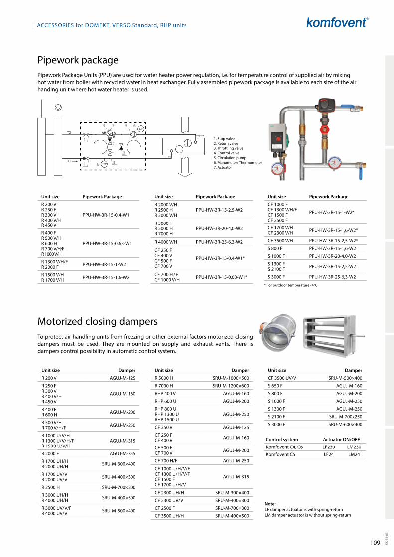
109 KK-1
8-03
ACCESSORIES for DOmEkt, VERSO Standard, RHP units
Pipework packagePipework Package Units (PPU) are used for water heater power regulation, i.e. for temperature control of supplied air by mixing hot water from boiler with recycled water in heat exchanger. Fully assembled pipework package is available to each size of the air handing unit where hot water heater is used.
1. stop valve2. return valve3. throttling valve4. Control valve5. Circulation pump6. manometer/ thermometer7. Actuator
Unit size Pipework Package
r 200 Vr 250 Fr 300 Vr 400 V/Hr 450 V
PPU-HW-3r-15-0,4-W1
r 400 Fr 500 V/Hr 600 Hr 700 V/H/Fr 1000 V/H
PPU-HW-3r-15-0,63-W1
r 1300 V/H/Fr 2000 F PPU-HW-3r-15-1-W2
r 1500 V/Hr 1700 V/H PPU-HW-3r-15-1,6-W2
* For outdoor temperature -4°C
4 5 6
6
7
1
1
2
3
2
Unit size Pipework Package
r 2000 V/Hr 2500 Hr 3000 V/H
PPU-HW-3r-15-2,5-W2
r 3000 Fr 5000 Hr 7000 H
PPU-HW-3r-20-4,0-W2
r 4000 V/H PPU-HW-3r-25-6,3-W2
CF 250 FCF 400 VCF 500 FCF 700 V
PPU-HW-3r-15-0,4-W1*
CF 700 H / FCF 1000 V/H PPU-HW-3r-15-0,63-W1*
Unit size Pipework Package
CF 1000 FCF 1300 V/H/FCF 1500 FCF 2500 F
PPU-HW-3r-15-1-W2*
CF 1700 V/HCF 2300 V/H PPU-HW-3r-15-1,6-W2*
CF 3500 V/H PPU-HW-3r-15-2,5-W2*
s 800 F PPU-HW-3r-15-1,6-W2
s 1000 F PPU-HW-3r-20-4,0-W2
s 1300 Fs 2100 F PPU-HW-3r-15-2,5-W2
s 3000 F PPU-HW-3r-25-6,3-W2
Unit size Damper
r 200 V AGUJ-m-125
r 250 Fr 300 Vr 400 V/Hr 450 V
AGUJ-m-160
r 400 Fr 600 H AGUJ-m-200
r 500 V/Hr 700 V/H/F AGUJ-m-250
r 1000 U/V/H r 1300 U/V/H/Fr 1500 U/V/H
AGUJ-m-315
r 2000 F AGUJ-m-355
r 1700 UH/Hr 2000 UH/H srU-m-300×400
r 1700 UV/Vr 2000 UV/V srU-m-400×300
r 2500 H srU-m-700×300
r 3000 UH/Hr 4000 UH/H srU-m-400×500
r 3000 UV/V/Fr 4000 UV/V srU-m-500×400
Unit size Damper
r 5000 H srU-m-1000×500
r 7000 H srU-m-1200×600
rHP 400 V AGUJ-m-160
rHP 600 U AGUJ-m-200
rHP 800 UrHP 1300 U rHP 1500 U
AGUJ-m-250
CF 250 V AGUJ-m-125
CF 250 FCF 400 V AGUJ-m-160
CF 500 FCF 700 V AGUJ-m-200
CF 700 H/F AGUJ-m-250
CF 1000 U/H/V/FCF 1300 U/H/V/FCF 1500 FCF 1700 U/H/V
AGUJ-m-315
CF 2300 UH/H srU-m-300×400
CF 2300 UV/V srU-m-400×300
CF 2500 F srU-m-700×300
CF 3500 UH/H srU-m-400×500
motorized closing dampersto protect air handling units from freezing or other external factors motorized closing dampers must be used. they are mounted on supply and exhaust vents. there is dampers control possibili ty in automatic control system.
Control system Actuator ON/OFF
komfovent C4, C6 LF230 Lm230
komfovent C5 LF24 Lm24
Note:LF damper actuator is with spring-return Lm damper actuator is without spring-return
Unit size Damper
CF 3500 UV/V srU-m-500×400
s 650 F AGUJ-m-160
s 800 F AGUJ-m-200
s 1000 F AGUJ-m-250
s 1300 F AGUJ-m-250
s 2100 F srU-m-700x250
s 3000 F srU-m-600×400
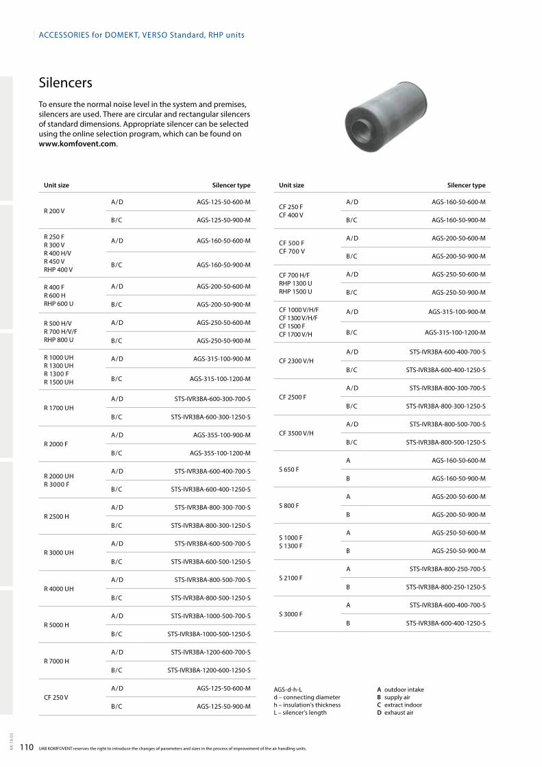
110KK-1
8-03
ACCESSORIES for DOmEkt, VERSO Standard, RHP units
UAB kOmFOVENt reserves the right to introduce the changes of parameters and sizes in the process of improvement of the air handling units.
silencersto ensure the normal noise level in the system and pre mises, silencers are used. there are circular and rectangular silencers of standard dimensions. Appropriate silencer can be selected using the online selection program, which can be found on www.komfovent.com.
AGs-d-h-Ld – connecting diameterh – insulation’s thicknessL – silencer’s length
A outdoor intakeB supply airC extract indoorD exhaust air
Unit size Silencer type
r 200 VA/D AGs-125-50-600-m
B/C AGs-125-50-900-m
r 250 Fr 300 Vr 400 H/Vr 450 V rHP 400 V
A/D AGs-160-50-600-m
B/C AGs-160-50-900-m
r 400 Fr 600 HrHP 600 U
A/D AGs-200-50-600-m
B/C AGs-200-50-900-m
r 500 H/Vr 700 H/V/FrHP 800 U
A/D AGs-250-50-600-m
B/C AGs-250-50-900-m
r 1000 UHr 1300 UHr 1300 F r 1500 UH
A/D AGs-315-100-900-m
B/C AGs-315-100-1200-m
r 1700 UHA/D sts-IVr3BA-600-300-700-s
B/C sts-IVr3BA-600-300-1250-s
r 2000 FA/D AGs-355-100-900-m
B/C AGs-355-100-1200-m
r 2000 UHr 3000 F
A/D sts-IVr3BA-600-400-700-s
B/C sts-IVr3BA-600-400-1250-s
r 2500 HA/D sts-IVr3BA-800-300-700-s
B/C sts-IVr3BA-800-300-1250-s
r 3000 UHA/D sts-IVr3BA-600-500-700-s
B/C sts-IVr3BA-600-500-1250-s
r 4000 UHA/D sts-IVr3BA-800-500-700-s
B/C sts-IVr3BA-800-500-1250-s
r 5000 HA/D sts-IVr3BA-1000-500-700-s
B/C sts-IVr3BA-1000-500-1250-s
r 7000 HA/D sts-IVr3BA-1200-600-700-s
B/C sts-IVr3BA-1200-600-1250-s
CF 250 VA/D AGs-125-50-600-m
B/C AGs-125-50-900-m
Unit size Silencer type
CF 250 FCF 400 V
A/D AGs-160-50-600-m
B/C AGs-160-50-900-m
CF 500 FCF 700 V
A/D AGs-200-50-600-m
B/C AGs-200-50-900-m
CF 700 H/FrHP 1300 UrHP 1500 U
A/D AGs-250-50-600-m
B/C AGs-250-50-900-m
CF 1000 V/H/FCF 1300 V/H/FCF 1500 FCF 1700 V/H
A/D AGs-315-100-900-m
B/C AGs-315-100-1200-m
CF 2300 V/HA/D sts-IVr3BA-600-400-700-s
B/C sts-IVr3BA-600-400-1250-s
CF 2500 FA/D sts-IVr3BA-800-300-700-s
B/C sts-IVr3BA-800-300-1250-s
CF 3500 V/HA/D sts-IVr3BA-800-500-700-s
B/C sts-IVr3BA-800-500-1250-s
s 650 FA AGs-160-50-600-m
B AGs-160-50-900-m
s 800 FA AGs-200-50-600-m
B AGs-200-50-900-m
s 1000 Fs 1300 F
A AGs-250-50-600-m
B AGs-250-50-900-m
s 2100 FA sts-IVr3BA-800-250-700-s
B sts-IVr3BA-800-250-1250-s
s 3000 FA sts-IVr3BA-600-400-700-s
B sts-IVr3BA-600-400-1250-s
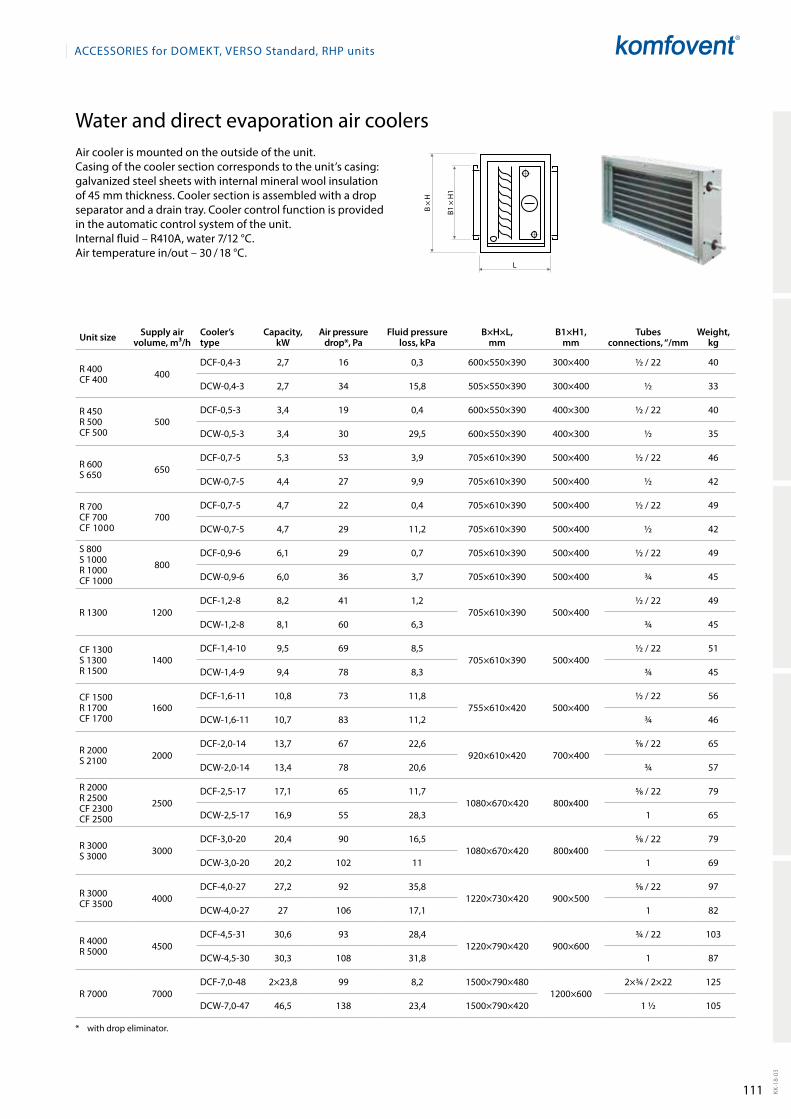
111 KK-1
8-03
B ×
H
B1 ×
H1
L
ACCESSORIES for DOmEkt, VERSO Standard, RHP units
Air cooler is mounted on the outside of the unit.Casing of the cooler section corresponds to the unit’s ca sing: galvanized steel sheets with internal mineral wool insulation of 45 mm thickness. Cooler section is assembled with a drop separator and a drain tray. Cooler control function is provided in the automatic control system of the unit.Internal fluid – r410A, water 7/12 °C.Air temperature in/out – 30 / 18 °C.
* with drop eliminator.
Unit size Supply air volume, m³/h
Cooler’s type
Capacity, kW
Air pressure drop*, Pa
Fluid pressure loss, kPa
B×H×L, mm
B1×H1, mm
Tubes connections, “/mm
Weight, kg
r 400CF 400 400
DCF-0,4-3 2,7 16 0,3 600×550×390 300×400 ½ / 22 40
DCW-0,4-3 2,7 34 15,8 505×550×390 300×400 ½ 33
r 450r 500CF 500
500DCF-0,5-3 3,4 19 0,4 600×550×390 400×300 ½ / 22 40
DCW-0,5-3 3,4 30 29,5 600×550×390 400×300 ½ 35
r 600s 650 650
DCF-0,7-5 5,3 53 3,9 705×610×390 500×400 ½ / 22 46
DCW-0,7-5 4,4 27 9,9 705×610×390 500×400 ½ 42
r 700CF 700CF 1000
700DCF-0,7-5 4,7 22 0,4 705×610×390 500×400 ½ / 22 49
DCW-0,7-5 4,7 29 11,2 705×610×390 500×400 ½ 42
s 800s 1000r 1000CF 1000
800DCF-0,9-6 6,1 29 0,7 705×610×390 500×400 ½ / 22 49
DCW-0,9-6 6,0 36 3,7 705×610×390 500×400 ¾ 45
r 1300 1200DCF-1,2-8 8,2 41 1,2
705×610×390 500×400½ / 22 49
DCW-1,2-8 8,1 60 6,3 ¾ 45
CF 1300s 1300r 1500
1400DCF-1,4-10 9,5 69 8,5
705×610×390 500×400½ / 22 51
DCW-1,4-9 9,4 78 8,3 ¾ 45
CF 1500r 1700CF 1700
1600DCF-1,6-11 10,8 73 11,8
755×610×420 500×400½ / 22 56
DCW-1,6-11 10,7 83 11,2 ¾ 46
r 2000 s 2100 2000
DCF-2,0-14 13,7 67 22,6920×610×420 700×400
5�8 / 22 65
DCW-2,0-14 13,4 78 20,6 ¾ 57
r 2000r 2500CF 2300CF 2500
2500DCF-2,5-17 17,1 65 11,7
1080×670×420 800x4005�8 / 22 79
DCW-2,5-17 16,9 55 28,3 1 65
r 3000s 3000 3000
DCF-3,0-20 20,4 90 16,51080×670×420 800x400
5�8 / 22 79
DCW-3,0-20 20,2 102 11 1 69
r 3000CF 3500 4000
DCF-4,0-27 27,2 92 35,81220×730×420 900×500
5�8 / 22 97
DCW-4,0-27 27 106 17,1 1 82
r 4000r 5000 4500
DCF-4,5-31 30,6 93 28,41220×790×420 900×600
¾ / 22 103
DCW-4,5-30 30,3 108 31,8 1 87
r 7000 7000DCF-7,0-48 2×23,8 99 8,2 1500×790×480
1200×6002×¾ / 2×22 125
DCW-7,0-47 46,5 138 23,4 1500×790×420 1 ½ 105
Water and direct evaporation air coolers
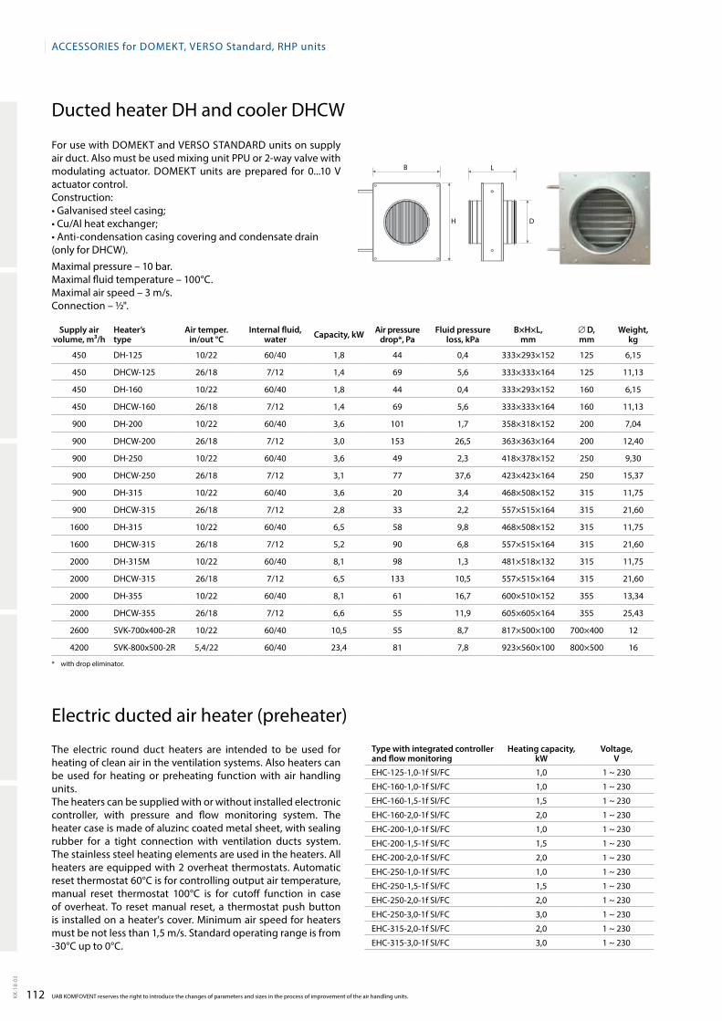
112KK-1
8-03
B
H D
L
ACCESSORIES for DOmEkt, VERSO Standard, RHP units
UAB kOmFOVENt reserves the right to introduce the changes of parameters and sizes in the process of improvement of the air handling units.
* with drop eliminator.
Supply air volume, m³/h
Heater’s type
Air temper. in/out °C
Internal fluid,water Capacity, kW Air pressure
drop*, PaFluid pressure
loss, kPaB×H×L,
mm∅ D, mm
Weight, kg
450 DH-125 10/22 60/40 1,8 44 0,4 333×293×152 125 6,15
450 DHCW-125 26/18 7/12 1,4 69 5,6 333×333×164 125 11,13
450 DH-160 10/22 60/40 1,8 44 0,4 333×293×152 160 6,15
450 DHCW-160 26/18 7/12 1,4 69 5,6 333×333×164 160 11,13
900 DH-200 10/22 60/40 3,6 101 1,7 358×318×152 200 7,04
900 DHCW-200 26/18 7/12 3,0 153 26,5 363×363×164 200 12,40
900 DH-250 10/22 60/40 3,6 49 2,3 418×378×152 250 9,30
900 DHCW-250 26/18 7/12 3,1 77 37,6 423×423×164 250 15,37
900 DH-315 10/22 60/40 3,6 20 3,4 468×508×152 315 11,75
900 DHCW-315 26/18 7/12 2,8 33 2,2 557×515×164 315 21,60
1600 DH-315 10/22 60/40 6,5 58 9,8 468×508×152 315 11,75
1600 DHCW-315 26/18 7/12 5,2 90 6,8 557×515×164 315 21,60
2000 DH-315m 10/22 60/40 8,1 98 1,3 481×518×132 315 11,75
2000 DHCW-315 26/18 7/12 6,5 133 10,5 557×515×164 315 21,60
2000 DH-355 10/22 60/40 8,1 61 16,7 600×510×152 355 13,34
2000 DHCW-355 26/18 7/12 6,6 55 11,9 605×605×164 355 25,43
2600 sVk-700x400-2r 10/22 60/40 10,5 55 8,7 817×500×100 700×400 12
4200 sVk-800x500-2r 5,4/22 60/40 23,4 81 7,8 923×560×100 800×500 16
For use with Domekt and Verso stANDArD units on supply air duct. Also must be used mixing unit PPU or 2-way valve with modulating actuator. Domekt units are prepared for 0...10 V actuator control.Construction: • Galvanised steel casing; • Cu/Al heat exchan ger; • Anti-condensation casing covering and condensate drain (only for DHCW).
maximal pressure – 10 bar.maximal fluid temperature – 100°C.maximal air speed – 3 m/s.Connection – ½".
Ducted heater DH and cooler DHCW
the electric round duct heaters are intended to be used for heating of clean air in the ventilation systems. Also heaters can be used for heating or preheating function with air handling units.the heaters can be supplied with or without installed electronic controller, with pressure and flow monitoring system. the heater case is made of aluzinc coated metal sheet, with sealing rubber for a tight connection with ventilation ducts system. the stainless steel heating elements are used in the heaters. All heaters are equipped with 2 overheat thermostats. Automatic reset thermostat 60°C is for controlling output air temperature, manual reset thermostat 100°C is for cutoff function in case of overheat. to reset manual reset, a thermostat push button is installed on a heater's cover. minimum air speed for heaters must be not less than 1,5 m/s. standard operating range is from -30°C up to 0°C.
Type with integrated controller and flow monitoring
Heating capacity, kW
Voltage, V
eHC-125-1,0-1f sI/FC 1,0 1 ~ 230
eHC-160-1,0-1f sI/FC 1,0 1 ~ 230
eHC-160-1,5-1f sI/FC 1,5 1 ~ 230
eHC-160-2,0-1f sI/FC 2,0 1 ~ 230
eHC-200-1,0-1f sI/FC 1,0 1 ~ 230
eHC-200-1,5-1f sI/FC 1,5 1 ~ 230
eHC-200-2,0-1f sI/FC 2,0 1 ~ 230
eHC-250-1,0-1f sI/FC 1,0 1 ~ 230
eHC-250-1,5-1f sI/FC 1,5 1 ~ 230
eHC-250-2,0-1f sI/FC 2,0 1 ~ 230
eHC-250-3,0-1f sI/FC 3,0 1 ~ 230
eHC-315-2,0-1f sI/FC 2,0 1 ~ 230
eHC-315-3,0-1f sI/FC 3,0 1 ~ 230
electric ducted air heater (preheater)
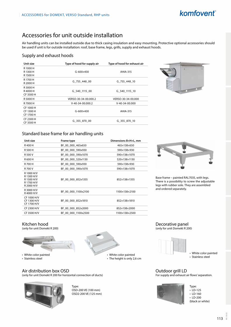
113 KK-1
8-03
ACCESSORIES for DOmEkt, VERSO Standard, RHP units
Accessories for unit outside installation
standard base frame for air handling units
supply and exhaust hoods
Unit size Frame type Dimensions B×H×L, mm
r 400 H BF_00_000_465x650 465×138×650
r 500 H BF_00_000_590x930 590×138×930
r 500 V BF_00_000_590x1070 590×138×1070
r 600 H BF_00_000_520x1130 520×138×1130
r 700 H BF_00_000_590x930 590×138×930
r 700 V BF_00_000_590x1070 590×138×1070
r 1000 H/Vr 1300 H/Vr 1500 H/Vr 1700 H/Vr 2000 H/V
BF_00_000_852x1355 852×138×1355
r 3000 H/Vr 4000 H/V BF_00_000_1100x2100 1100×138×2100
CF 1000 H/VCF 1300 H/VCF 1700 H/V
BF_00_000_852x1810 852×138×1810
CF 2300 H/V BF_00_000_852x2000 852×138×2000
CF 3500 H/V BF_00_000_1100x2500 1100×138×2500
Air distribution box osD(only for unit Domekt r 200 for horizontal connection of ducts)
type:• LD-125• LD-160• LD-200 (black or white)
type:osD-200 Ve (100 mm)osD2-200 Ve (125 mm)
kitchen hood(only for unit Domekt r 200)
Decorative panel(only for unit Domekt r 200)
• White color painted • Stainless steel
• White color painted • Stainless steel
• White color painted• The height is only 2,6 cm
Base frame – painted rAL7035, with legs.there is a possibility to screw the adjustable legs with rubber sole. they are assembledand ordered separately.
Air handling units can be installed outside due to thick casing insulation and easy mounting. Protective optional accessories should be used if unit is for outside installation: roof, base frame, legs, grills, supply and exhaust hoods.
Unit size Type of hood for supply air Type of hood for exhaust air
r 1000 Hr 1300 Hr 1500 H
G-600×430 AHIA-315
r 1700 Hr 2000 H G_755_448_00 G_755_448_10
r 3000 Hr 4000 HCF 3500 H
G_540_1115_00 G_540_1115_10
r 5000 H Verso-30-34-00.000.2 Verso-30-34-00.000
r 7000 H V-40-34-00.000.2 V-40-34-00.000
CF 1000 HCF 1300 HCF 1700 H
G-600×430 AHIA-315
CF 2300 HCF 3500 H G_355_870_00 G_355_870_10
outdoor grill LDFor supply and exhaust air flows’ separation.
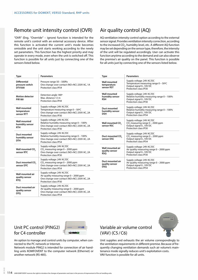
114KK-1
8-03
ACCESSORIES for DOmEkt, VERSO Standard, RHP units
UAB kOmFOVENt reserves the right to introduce the changes of parameters and sizes in the process of improvement of the air handling units.
remote unit intensity control (oVr)“oVr” (eng. “override” – ignore) function is intended for the remote unit’s control with an external accessory device. After this function is activated the current unit’s mode becomes omissible and the unit starts working according to the newly set parameters. this function has the highest priority and may operate in every mode, even when the unit is switched off. this function is possible for all units just by connecting one of the sensors listed below.
Air quality control (AQ)AQ ventilation intensity control option according to the external sensor signal. Provides ventilation intensity correction, according to the increased Co2, humidity level, etc. A different AQ function may be set depending on the sensor type, therefore, the intensity of the unit will be regulated accordingly. User can activate this function anytime according to the demand and can also observe the premise’s air quality on the panel. this function is possible for all units just by connecting one of the sensors listed below.
Variable air volume control (VAV) (C5 / C6)Unit supplies and exhausts the air volume correspondingly to the ventilation requirements in different premise. Because of fre-quently chan ging ventilation demands such air volume’s main-tenance mode signally reduces unit’s exploitation costs. VAV function is possible for all units.
Unit PC control (PING2) for C4 controllerAn option to manage and control units by computer, when con-nected to the PC network or Internet.Network module PING2 is intended for connection of air hand-ling units komFoVeNt to the computer network (ethernet) or another network (rs-485).
Type Parameters
Differential pressure switch DTV500
Pressure range 50 – 500Paone change-over contact (No+NC) 250V AC, 1AProtection class IP54
Motion detector PIR180
Detection angle 180ºmax. distance 12 mProtection class IP44
Wall mounted temperature sensor RTT
supply voltage: 24V AC/DCtemperature measuring range 0 – 50ºCone change-over contact (No+NC) 250V AC, 2AProtection class IP30
Wall mounted humidity sensor RTH
supply voltage: 24V AC/DCrelative humidity measuring range 0 – 100%one change-over contact (No+NC) 250V AC, 2AProtection class IP30
Duct mounted humidity sensor DTH
supply voltage: 24V AC/DCrelative humidity measuring range 0 – 100%one change-over contact (No+NC) 250V AC, 2AProtection class IP54
Wall mounted CO2 sensor RTC
supply voltage: 24V AC/DCCo2 measuring range 0 – 2000 ppmone change-over contact (No+NC) 250V AC, 2AProtection class IP30
Duct mounted CO2 sensor DTC
supply voltage: 24V AC/DCCo2 measuring range 0 – 2000 ppmone change-over contact (No+NC) 250V AC, 2AProtection class IP54
Wall mounted air quality sensor RTQ
supply voltage: 24V AC/DCAir quality measuring range 0 – 2000 ppmone change-over contact (No+NC) 250V AC, 2AProtection class IP30
Duct mounted air quality sensor DTQ
supply voltage: 24V AC/DCAir quality measuring range 0 – 2000 ppmone change-over contact (No+NC) 250V AC, 2AProtection class IP54
Type Parameters
Wall mounted temperature sensor RST
supply voltage: 24V AC/DCtemperature measuring range 0 – 50ºCoutput signal 0...10V DCProtection class IP30
Wall mounted humidity sensor RSH
supply voltage: 24V AC/DCrelative humidity measuring range 0 – 100%output signal 0...10V DCProtection class IP30
Duct mounted humidity sensor DSH
supply voltage: 24V AC/DCrelative humidity measuring range 0 – 100%output signal 0...10V DCProtection class IP54
Wall mounted CO2 sensor RSC
supply voltage: 24V AC/DCCo2 measuring range 0 – 2000 ppmoutput signal 0...10V DCProtection class IP30
Duct mounted CO2 sensor DSC
supply voltage: 24V AC/DCCo2 measuring range 0 – 2000 ppmoutput signal 0...10V DCProtection class IP54
Wall mounted air quality sensorRSQ
supply voltage: 24V AC/DCAir quality measuring range 0 – 2000 ppmoutput signal 0...10V DCProtection class IP30
Duct mounted air quality sensor DSQ
supply voltage: 24V AC/DCAir quality measuring range 0 – 2000 ppmoutput signal 0...10V DCProtection class IP54
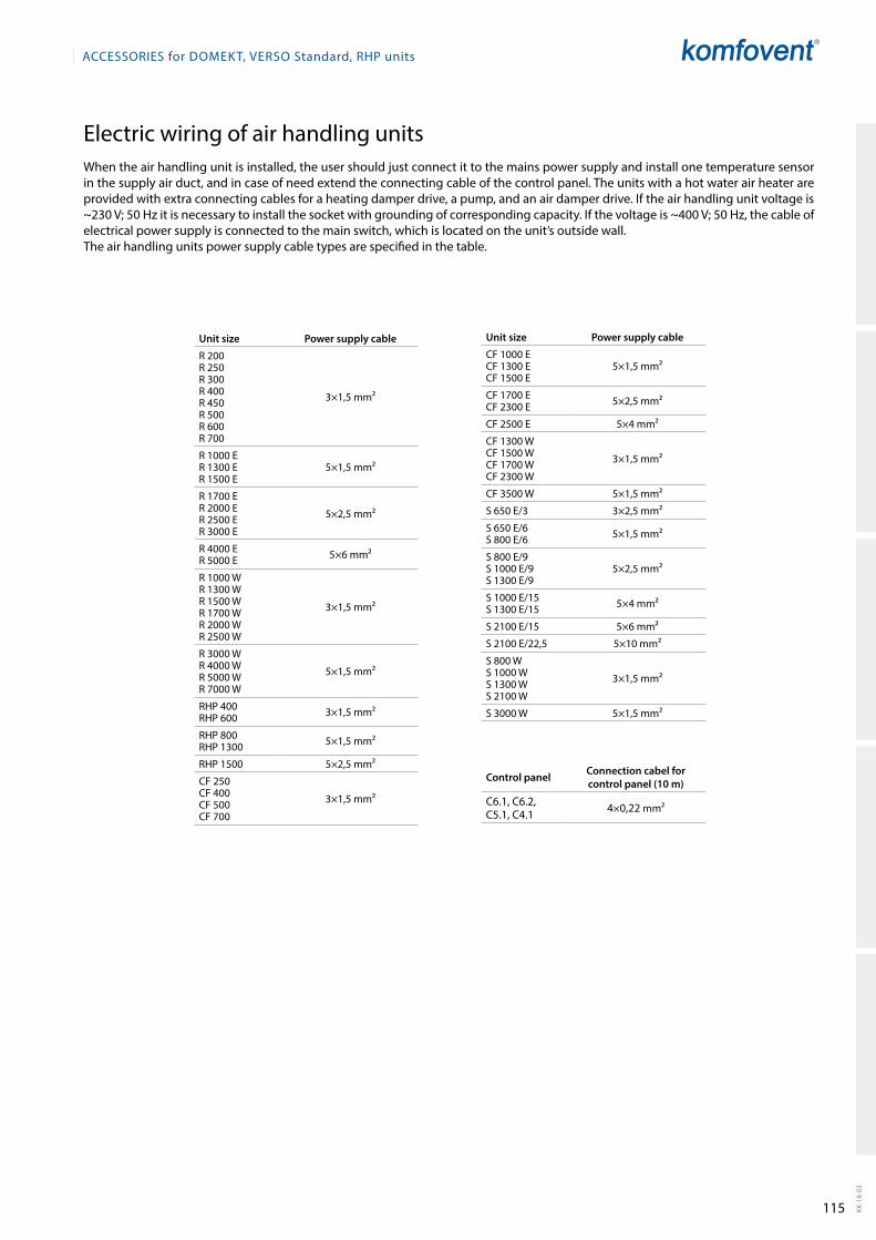
115 KK-1
8-03
ACCESSORIES for DOmEkt, VERSO Standard, RHP units
electric wiring of air handling unitsWhen the air handling unit is installed, the user should just connect it to the mains power supply and install one temperature sensor in the supply air duct, and in case of need extend the connecting cable of the control panel. the units with a hot water air heater are provided with extra connecting cables for a heating damper drive, a pump, and an air damper drive. If the air handling unit voltage is ~230 V; 50 Hz it is necessary to install the socket with grounding of corresponding capacity. If the voltage is ~400 V; 50 Hz, the cable of electrical power supply is connected to the main switch, which is located on the unit’s outside wall.the air handling units power supply cable types are specified in the table.
Control panel Connection cabel for control panel (10 m)
C6.1, C6.2, C5.1, C4.1 4×0,22 mm2
Unit size Power supply cable
r 200r 250r 300r 400r 450r 500r 600r 700
3×1,5 mm2
r 1000 er 1300 er 1500 e
5×1,5 mm2
r 1700 er 2000 er 2500 er 3000 e
5×2,5 mm2
r 4000 er 5000 e 5×6 mm2
r 1000 Wr 1300 Wr 1500 Wr 1700 Wr 2000 Wr 2500 W
3×1,5 mm2
r 3000 Wr 4000 Wr 5000 Wr 7000 W
5×1,5 mm2
rHP 400rHP 600 3×1,5 mm2
rHP 800rHP 1300 5×1,5 mm2
rHP 1500 5×2,5 mm2
CF 250CF 400CF 500CF 700
3×1,5 mm2
Unit size Power supply cable
CF 1000 eCF 1300 eCF 1500 e
5×1,5 mm2
CF 1700 eCF 2300 e 5×2,5 mm2
CF 2500 e 5×4 mm2
CF 1300 WCF 1500 WCF 1700 WCF 2300 W
3×1,5 mm2
CF 3500 W 5×1,5 mm2
s 650 e/3 3×2,5 mm2
s 650 e/6s 800 e/6 5×1,5 mm2
s 800 e/9s 1000 e/9s 1300 e/9
5×2,5 mm2
s 1000 e/15s 1300 e/15 5×4 mm2
s 2100 e/15 5×6 mm2
s 2100 e/22,5 5×10 mm2
s 800 Ws 1000 Ws 1300 Ws 2100 W
3×1,5 mm2
s 3000 W 5×1,5 mm2
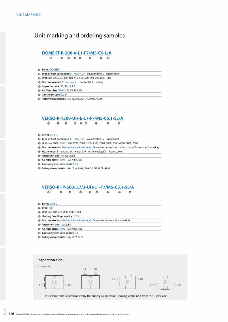
116KK-1
8-03
UAB KOMFOVENT reserves the right to introduce the changes of parameters and sizes in the process of improvement of the air handling units.
UNIt mArkING
Unit marking and ordering samples
VERSO-RHP-600-3.7/3-UH-L1-F7/M5-C5.1-SL/A
VERSO-R-1300-UH-E-L1-F7/M5-C5.1-SL/A
DOMEKT-R-200-V-L1-F7/M5-C6-L/A
Series: Verso
Type of heat exchanger: R – rotary; CF – counter flow; S – supply unit
Unit size: 1000, 1300, 1500, 1700, 2000, 2100, 2300, 2500, 3000, 3500, 4000, 5000, 7000
Duct connection: UH – universal/horizontal; UV – universal/vertical; H – horizontal; V – vertical; F – ceiling
Heater type: e – electric; W – water; CW – water cooler; DX – freon cooler
Inspection side: R1; R2; L1; L2
Аir filter class: F7/M5; F7/F7; M5/M5
Control system with panel: C5.1
Rotary characteristic: L/A; sL/A; L/AZ; SL/AZ; L/AZM; SL/AZM
Series: Verso
Type: rHP
Unit size: 400, 600, 800, 1300, 1500
Heating / cooling capacity: 3.7/3
Duct connection: UH – universal/horizontal; UV – universal/vertical; V – vertical
Inspection side: L1; L2; R1
Аir filter class: F7/M5; F7/F7; M5/M5
Control system with panel: C5.1
Rotary characteristic: L/A; XL/A; sL/A
Series: Domekt
Type of heat exchanger: R – rotary; CF – counter flow; S – supply unit
Unit size: 200, 250, 300, 400, 450, 500, 600, 650, 700, 800, 1000
Duct connection: V – vertical; H – horizontal; F – ceiling
Inspection side: R1; R2; L1; L2
Аir filter class: F7/M5; F7/F7; M5/M5
Control system: C6, C4
Rotary characteristic: L/A; SL/A; L/AZ; L/AZM; SL/AZM
Inspection side:
L1 L2
L1
L1
r1 r2
r1
r1
H V F F
supply air
Inspection side is determined by the supply air direction, looking at the unit from the user‘s side.
Notes


![[kk| mRiknu &I - CBSEcbseacademic.nic.in › web_material › Curriculum › Vocational › 2017 › … · [kk| mRiknu & I d{kk XI dnzh; ek/;fed f’k{kk cksMZ 2] lkeqnkf;d dsanz]](https://static.fdocuments.net/doc/165x107/5f0c4fcf7e708231d434c5dd/kk-mriknu-i-a-webmaterial-a-curriculum-a-vocational-a-2017-a.jpg)