VENDING MACHINE ENERGY EFFICIENCY DEVICE ... MACHINE ENERGY EFFICIENCY DEVICE ENGINEERING EVALUATION...
21
Report BAY-00159 (Rev. 1) VENDING MACHINE ENERGY EFFICIENCY DEVICE ENGINEERING EVALUATION AND TEST REPORT Bayview Technology Model: Vending Mi$er Serial No. 1200-260 (Evaluation Unit) 1200-261 (Test Unit) Prepared for: Mr. David J. Schanin President Bayview Technology Group, Inc. 1091 Industrial Rd., Suite 106 San Carlos, CA 94070 Prepared by: Foster-Miller, Inc. 195 Bear Hill Rd. Waltham, MA 02451-1003 June 1, 2000
Transcript of VENDING MACHINE ENERGY EFFICIENCY DEVICE ... MACHINE ENERGY EFFICIENCY DEVICE ENGINEERING EVALUATION...

Report BAY-00159 (Rev. 1)
VENDING MACHINE ENERGY EFFICIENCY DEVICEENGINEERING EVALUATION AND TEST REPORT
Bayview Technology
Model: Vending Mi$erSerial No. 1200-260 (Evaluation Unit)
1200-261 (Test Unit)
Prepared for:
Mr. David J. SchaninPresidentBayview Technology Group, Inc.1091 Industrial Rd., Suite 106San Carlos, CA 94070
Prepared by:
Foster-Miller, Inc.195 Bear Hill Rd.Waltham, MA 02451-1003
June 1, 2000

Report BAY-00159 (Rev. 1)
VENDING MACHINEENGINEERING EVALUATION AND TEST REPORT
Bayview Technology
Model: Vending Mi$erSerial No. 1200-260 (Evaluation Unit)
1200-261 (Test Unit)
Prepared for:
Mr. David J. SchaninPresident
Bayview Technology Group, Inc.1091 Industrial Rd., Suite 106
San Carlos, CA 94070
Prepared by:
Foster-Miller, Inc.195 Bear Hill Rd.
Waltham, MA 02451-1003
June 1, 2000

A-Advantage O-ObservationD-Disadvantage R-Recommendation
1
1. Engineering Evaluation
The Vending Mi$er (VM) was carefully inspected and disassembled, as required, to gain visualaccess to internal components. The evaluation included the three categories outlined below.
IntegrityGeneral impression of how components satisfy their design function, including areas such assuitability, durability, safety and simplicity.
Manufacturing QualityHow well the device was fabricated, assembled, adjusted, etc.
ServiceabilityHow easily the device is set up.
A numerical rating of 1 (poor) to 5 (excellent) was assigned for each category. Comments wereprovided for each category and classified as advantages, disadvantages or observations. Asnecessary, the comments will be followed with recommended improvements. We relied onBayview to provide FMI with schematics, assembly drawings and component information.Engineering Evaluation Scores are provided in Table 1.
1.1 Mechanical
A The control box is a robust molded plastic two-piece assembly. The plastic walls arerelatively thick. Four screws secure the two halves.
A/D A robust plated steel wall mounting bracket is provided. No mounting screws wereprovided.
A Large molded strain relief on power cord.
A/D The motion sensor is contained in a robust, two-piece, plastic enclosure. It is designedfor flat wall or inside corner mounting. Front-to-back angular adjustment is provided.This component is manufactured by Sensor Switch, Inc. No mounting screws wereprovided.
A A conventional telephone type cable/connectors is used to connect the sensor to thecontrol unit – less expensive due to high volume production. Connectors lock in place.Known reliability.
A Circuit boards appear to be of high quality – glass reinforced.
A Component mounting and soldering are very good.
A Two-page instruction manual provided separately.
2
1.2 Electrical Review
A brief electrical evaluation was performed. Emphasis was placed on the components mostlikely to fail. The results are as follows:
Vending Machine Power Requirements 11 amp @ 120 VAC1/3 HP
RelayMfg. SiemensModel RT Series
UL/CSA Recognized16 amp @ 240 VAC
½ HP @ 120 VAC30,000 Operations at approximately 12 amps general purpose current*
Life @ 6 Operations / Day greater than 13 years*
Transformer UL/CSA RecognizedModel 4-01-3010Current rating 0.25 AmpIsolation 2500 V RMS
Receptacle 15 ampPower cord UL Recognized
16-3 SJWRating 13 Amp @ 105°C
Electrical Conclusions:This product meets all of the power requirements for controlling vending machines with theratings listed above. General construction and labeling are excellent.
* Please note that relay cycle life is based on the older vending machines with mechanicalthermostats that start under full compressor motor current and open under limitedload which consists of all devices except the compressor and condenser fan. These twodevices shut off before the VM relay opens. If used with the newer, electronicthermostat machines, life should be greater because the compressor and condenser fanturn on minutes after the VM relay closes.

3
Table 1. Overall Engineering Evaluation Results
Engineering Evaluation Ratings 1 2 3 4 5
ManufacturerModel
Poor Fair Good V. Good ExcellentA passing score is ≥ 3
Integrity Mfg. Quality ServiceabilityBayview Technology
Vending Mi$er 4.5 4 5
2. Performance Testing
To verify that the VM is not detrimental to beverage temperature during its power–down mode,we tested it on a Vendo Model 630 vending machine. The following test procedure wasfollowed.
2.1 Setup
♦ Locate the vending machine in a 90°F test chamber.
♦ Fully load the machine with 20 oz Pepsi beverage. Locate 18 instrumented bottles in the loadof beverage by placing 6 instrumented bottles in the bottom layer at the four corners and twoat the center. Repeat this array every other layer (3 layers).
♦ Attach a thermocouple to the compressor discharge tube to monitor compressor activity.Locate an ambient temperature probe near the exterior of the vending machine.
♦ Connect a relay to the VM power output and attach the relay contacts to one channel of thetemperature data logger to provide a signal indicating that the vending machine has power.Mount the VM module and sensor as described in the manual.
2.2 Procedure
Ø Plug the vending machine into the metered (digital) power outlet and allow it to operate for atleast 48 hours in the 90°F ambient environment to assure steady-state operation has beenachieved.
Ø At the end of the 48+ hour cool-down period start the data logger to record the temperatures.Record the power meter reading. At the end of a 24 hour time period stop the data logger andrecord the power meter reading.

4
Ø Unplug the vending machine, install the VM in the power circuit, wait approximately 5minutes before plugging the vending machine into the VM to assure a low head pressure inthe compressor. Cover the sensor with a cardboard box to prevent light from entering andfalse triggering.
Ø Again start the data logger to record the temperatures. Record the power meter reading. Atthe end of a 24 hour time period record the power meter reading and time of reading. Keepthe data logger running.
Ø Enter the chamber at the end of the 24 hr time period and remove the box from the sensor tocause a VM response and machine power-up. Check the data logger periodically to see whenthe compressor cycles off. Stop the data logger once the compressor cycles off.
Ø Compare data with and without the VM installed.
3. Results
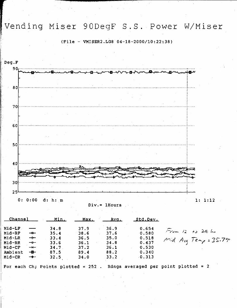
Results of the tests described in Section 2 are summarized below in Table 2. Raw test resultsgraphs are provided in Appendix A of this report. The peak beverage temperature recorded was41.1°. That bottle was located at the bottom (next-to-be-vended), left front. Averagetemperature for that bottle was 39.8°F.
The occupancy sensor was able to detect our presence at the end of the test and immediatelyreapplied electrical power to the vending machine. It kept electrical power on until therefrigeration system completed its cycle. This can be seen in the last graph in Appendix A.
Table 2. Test Results
Energy in 24 hr*Next-to-vend
BeverageAvg. Temp.
Third LayerBeverage
Avg. Temp.
Fifth LayerBeverage
Avg. Temp.Without VM 10,024 watt-hr 35°F 34.7°F 34.3°FWith VM 5,194 watt-hr 36.6°F 35.7°F 35.1°FChange 48.2% reduction +1.6°F +1°F +0.8°F
* The energy savings presented above is when there is no activity at the vending machine. Theamount of savings is dependent upon the time when there is no sensed activity near the vendingmachine.

5
4. Conclusions
The VM appears to be a well-constructed device both mechanically and electrically. Our testsindicate that it should reduce operating costs when used in conjunction with a conventionalbeverage vending machine. As shown in Table 2, the negative impact on beverage temperaturein minimal. The average next-to-be-vended beverage temperature increased less than 2°F and noinstrumented beverage exceeded the Pepsi-Cola maximum temperature of 42°F.
The energy savings test result presented is based on a 24 hour time period. Actual savings willbe less due to activity at the vending machine. If we assume that the machine is located in aplace of business and is idle, such as overnight, actual savings may be based on a 12 hour timeperiod which is approximately 2,400 watt-hours per day. In a facility that is open seven days aweek, this translates into a savings of approximately $88/yr at $0.10/kilowatt-hour or $131/yr at$0.15/Kw-hr. In a facility that is open five days a week, at 12 hours per day, and no vendingactivity on the weekends, this translates into a savings of $113/yr at $0.10/Kw-hr or $170/yr at$0.15/Kw-hr. These examples are based upon the Vendo Model 630 vending machine. Resultsmay vary when the VM is used in conjunction with other vending machines.
An additional benefit of the VM may be increased life of the compressor, condenser fan andfluorescent lamps. The compressor and condenser fan will cycle less and for longer periods oftime when the VM is in operation. Motors and compressors typically last longer if they arecycled less frequently even if the total on time remains the same.
Although a slight penalty in fluorescent lamp life will be realized because the lamp is switchedon and off, the benefit of the lamp off time will most likely be greater, thereby increasing thelamp replacement interval.

APPENDIX A
Performance Graphs

Graph Legend:
Bot -- Bottom bottles, next to be vendedMid -- Layer 3 from bottomTop -- Layer 5 from bottomLF -- Left-frontRF -- Right-frontLR -- Left-rearRR -- Right-rearCF -- Center-frontCR -- Center-rearAmbient -- Operating environment temperatureComp-HI -- Compressor discharge temperature


APPENDIX B
Vending Mi$er Manual
Relay Information

B A Y V I E WT E C H N O L O G Y
Bayview Technology Group, Inc.1091 Industrial Rd., Suite 106San Carlos, California 94070
www.bayviewtech.com
Telephone: (650) 596-1160FAX: (650) 593-0156
Sales/Service: (800) 770-8539Rev 2.0
VendingMI$ER™
Instructions forPermanentInstallation
VendingMiserTM (patent pending) is designed to operate as an intelligent power controller for cold product vendingmachines. Note that VendingMiser may not be used on any vending machine which contains perishable products.
General Theory of OperationUsing a Passive Infra Red (PIR) sensor, VendingMiser will automatically shut down the attached vending machinewhen the area around the machine has been vacant for 15 minutes. However, VendingMiser will periodically re-powerthe vending machine automatically to ensure that the vended product stays cold. The re-power period will be modifieddynamically based on the room's temperature - the warmer the room, the shorter the delay.In addition, VendingMiser contains a current sensor so it can determine if the vending machine's compressor is operat-ing. VendingMiser will delay power down of the vending machine until the compressor has completed its cooling cycle.To install the VendingMiser, follow these simple steps:
Please turn this sheet over to continue...
Locating the VendingMiser1. Unplug the vending machine's power cord from the outlet. If
it is necessary to move the machine, be careful as it can be veryheavy.
2. Identify a suitable mounting location for the VendingMiser. Themost likely place would be on the wall adjacent to or behindthe vending machine. The VendingMiser must be located sothat the machine's power card can reach VendingMiser, andVendingMiser's power cord can reach the power outlet. It isalso desirable to have the operational lights on VendingMiser be viewable by maintenance personnel. NOTE: DONOT locate VendingMiser lower than four feet above the floor if mounted behind the vending machine to ensurethat the compressor hot exhaust does not blow on VendingMiser. Failure to do so may damage the VendingMiser.
3. Using screws appropriate for the wall material, attach VendingMiser's mounting bracket to the identified location.Locate the lip inside the bracket at the lower edge, so that VendingMiser can be dropped down into the mountingbracket.
4. Plug the vending machine's power cord into the VendingMiser. Do not yet plug the VendingMiser into the walloutlet at this stage of the installation process.
Occupancy Sensor Installation5. The PIR sensor must now be mounted in an appropriate location. The sensor must be located so that it can "See"
anyone in front of or approaching the vending machine. The best location for the sensor is on the wall behind thevending machine, about two feet above the machine. If low ceiling height does not allow this, an optional locationis on the ceiling in front of the vending machine.
Green LED RedLED
AmberLED
OccupancySensor
Power to Vending Machine
Power InFromWallOutlet

VendingMI$ER™
B A Y V I E WT E C H N O L O G Y
Bayview Technology Group, Inc.1091 Industrial Rd., Suite 106San Carlos, California 94070
www.bayviewtech.com
Telephone: (650) 596-1160FAX: (650) 593-0156
Sales/Service: (800) 770-8539Rev 2.0
Instructions forPermanent
Installation (cont'd.)
Mounting the sensor to the ceiling requires that the "TOP" of the sensor where the cable exits points towards thevending machine to ensure proper occupancy detection.Avoid placement near ceiling air ducts, as the warm air currents they cause can falsely trigger the PIR sensor. Also,the hot air may mask the PIR sensor from seeing people in the area.
6. To mount the sensor, remove its rear cover by prying out the plastic but-ton on top of the sensor and tilting it out of the rear cover. Use thepredrilled plastic holes in the rear cover and the appropriate fasteners tosecure it to the surface or corner on which the sensor will be mounted.Then replace the sensor onto the rear cover and replace the plastic but-ton to hold the sensor in place.
7. The occupancy sensor has a telephone style connector at the end of itscable. After carefully uncoiling the cable, plug this connector into thecenter socket on the VendingMiser (see diagram over). Do NOT plug the sensor into anything other than theVendingMiser, or it may be damaged. It is highly recommended that the sensor cable be secured either by placingit behind the wall on which it is mounted, or by covering the cable with plastic low voltage wire raceway.
Power-Up Testing and Installation ValidationConnect the VendingMiser's power cord the wall outlet. The following events should occur:
Green LED OperationOn Unit OKOff Unit Failure
Red LED Operation - OccupancyOn Occupancy DetectedOff No Occupancy Detected
Amber LED Operation - CompressorOn Compressor ON
Blink Compressor ON-Power Off DelayedOff Compressor OFF
• The vending machine should power up immediately• The Green LED should flash twice to indicate that the tem-
perature sensor is functional• The Orange LED should then come on as the VendingMiser
attempts to synchronize with the compressor's operation.This typically will require that the compressor cycle on andoff once.
• The Red LED should come on, indicating that occupancy isdetected.
The PIR sensor must be allowed to warm up and stabilize for severalminutes before its placement can be verified. During this warm-upperiod, the sensor's Green LED may go dark – this is normal behavior. Once the sensor is warmed up, it will flashgreen at the slightest movement within its field of view. Validate that the sensor can "See" an occupant at or approach-ing the vending machine. If necessary, relocate the sensor and repeat the coverage test. The Red LED on the Vending-Miser will mirror the state of the PIR sensor, with an additional 5 second delay. This allows verification that theVendingMiser is communicating with the PIR sensor.
As a final functional test, the VendingMiser will power down the first time only after installation approximately twominutes after the area around the machine is vacant and the compressor is determined to be not running. Covering thePIR sensor or temporarily setting it to face the wall will allow validation of the power down operation if so desired.Following this initial power down, the VendingMiser will operate with standard timeouts.
Top
Data Cable

RT series (DC Coil)16 Amp PC Board Miniature Relay
Meets VDE 10mm Spacing, 5KV Dielectric
File E22575File LR15734NR 6106
Features• SPST through DPDT contact arrangements.• Immersion cleanable and flux tight versions available.• VDE 10mm spacing, 5kV dielectric, coil to contacts.• UL Class F coil insulation system.• Conforms to UL 508, 1873, 353 and 1950.• Low profile; 15.7mm height.• Sensitive coil; 400mW.• Withstand surge voltage of 10,000V.
Contact Data Arrangements: 1 Form A (SPST-NO) Wiring Diagram Code 1, 3.
2 Form A (DPST-NO) Wiring Diagram Code 5.1 Form C (SPDT) Wiring Diagram Code 1, 3.2 Form C (DPDT) Wiring Diagram Code 5.
Material: Silver-nickel 90/10.Minimum Load: 12V/100mA.Expected Mechanical Life: 10 million operations.Initial Contact Resistance: 100 milliohms max @ 1A 12VDC.
Designed to meet UL/CSA/VDE ratings with relay proper-ly vented. Remove vent nib after soldering and cleaning.
UL/CSA/VDE Ratings @ 25°C
Initial Dielectric StrengthBetween Open Contacts: >1,000VAC (1 minute).Between Poles (code 5): >2,500VAC (1 minute).Between Coil and Contacts: >5,000VAC (1 minute).Surge Voltage (DC): >10,000VAC x (1.2 x 50 µsec).
Coil Data @ 25°CVoltage: 5 to 48VDC.Nominal Power @ 25°C: 400mW.Duty Cycle: Continuous.Initial Insulation Resistance: 10,000 megohms, min., at 25°C, 500VDC
and 50% rel. humidity.
Operate Data @ 25°CMust Operate Voltage(DC): 70% of nominal.Must Release Voltage(DC): 10% of nominal.Operate Time (Excluding Bounce):
7 ms, typ., 15ms max. at nom. voltage.Release Time (Excluding Bounce):
3 ms, typ., 6ms max. at nom. voltage.
Environmental DataTemperature Range:
Storage: -40°C to +105°C.Operating: -40°C to +85°C at rated current.Vibration, Operational
N.O.:0.065”(1.65mm) max. excursions from 10 - 55 Hz:N.C.:0.032”(0.82mm) max. excursions from 10 - 55 Hz:
with no contact opening >10µs
Mechanical DataTermination: Printed circuit terminals.Enclosures: RT 1, 3, 4: Flux-tight, top vented, plastic case.
RT B, D, E: Immersion cleanable, plastic case.Weight: 0.35 oz. (10g) approximately.
DC Must NominalNominal Resistance Operate CoilVoltage in Ohms Voltage Current
VAC ±10% VAC (mA) – 50/60Hz.
005 62 3.5 80006 90 4.2 66.7009 202 6.3 44.4012 360 8.4 33.3018 810 12.6 22.2024 1,440 16.8 16.7048 5,760 33.6 8.3
Coil Data @ 25°C
Max. Ambient Temp. vs. Coil Voltage
60
100
140
180
220
260
300
0 20 40 60 80 100
0 A
A
B
Max. Allowable Ambient Temp. (°C)
Ap
plie
d C
oil
Vo
ltag
e (%
of
rate
d n
om
.)
8 A
16A12A
A: Coil temperature = Ambient temperature.B: 110% of nominal coil voltage at rated contact load.
* Form A only** Form B only
Code NO/NC Load Type Operations1 10A/10A @ 277VAC Resistive/GP 100K
10A/10A @ 30VDC Resistive 100K12A/12A @ 250VAC Resistive/GP 30K12A/12A @ 30VDC Resistive 30K3/4 HP @ 480VAC* Motor 6K1/2 HP @ 240VAC* Motor 6K1/3 HP @ 120VAC* Motor 6K
48 LRA/10 FLA @ 240VAC* Motor 30KTV-3 @ 120VAC* Tungsten 25K
A300, 720VA @ 240VAC* Pilot Duty 30K
3 16A/16A @ 250VAC Resistive/GP 50K20A/20A @ 277VAC Resistive/GP 30K20A/20A @ 24VDC Resistive 30K16A/16A @ 30VDC Resistive 30K1 HP @ 480VAC* Motor 6K1 HP @ 240VAC* Motor 6K
1/2 HP @ 120VAC* Motor 6K60 LRA/10 FLA @ 250VAC* Motor 30K
TV-5 @ 120VAC* Tungsten 25KA300, 720VA @ 240VAC* Pilot Duty 30KB300, 360VA @ 240VAC** Pilot Duty 30K
5 8A/8A @ 277VAC Resistive/GP 100K8A/8A @ 30VDC Resistive 100K
10A/10A @ 250VAC Resistive/GP 30K10A/10A @ 30VDC Resistive 30K1/2 HP @ 240VAC* Motor 6K1/4 HP @ 120VAC* Motor 6K
34.8 LRA/6 FLA @ 120VAC* Motor 30K17.4 LRA/5 FLA @ 240VAC* Motor 30KB300, 360VA @ 240VAC* Pilot Duty 30K
TV-3 @120VAC* Tungsten 25K