VDV Works Presents Lennie Lightwave's New Guide to Fiber ... · PDF fileVDV Works Presents...
50
© 2002-6, VDV Works LLC VDV Works Presents Lennie Lightwave's New Guide to Fiber Optics Lennie has been involved in fiber optics since he first went to "Fiber U" - Fotec's fiber optic installer conference in 1993. Lennie is now working with "VDV Works," a company that provides training, training materials and web content on fiber optics, structured cabling, computer networking and telecommunications. This guide is the outcome of more than 25 years of experience in fiber optics from Lennie and the VDV Works staff. For you it's easy to learn more about fiber optics! All you have to do is keep reading...... Also see Lennie online at www.LennieLightwave.com, where you can also see our program on OTDRs , "virtual hands-on" explanation of fiber optic termination and "virtual hands-on" explanation of fiber optic testing. Check back often or visit VDV Academy at http://www.vdvacademy.com/ and see how we'll keep adding material to keep everything up to date. Feel free to send us your comments at [email protected] - tell us how you like it and what you would like to see us change or add. Lennie's Uncle Ted is the expert on structured cabling, including Cat 5. See Uncle Ted's online guide to communications cabling at http://www.vdvworks.com/UncleTed/. Get certified in structured cabling and fiber optics. VDV Academy programs are pre- approved for FOA and SCA certification training, making it much easier to get yourself or your school approved by these organizations!
Transcript of VDV Works Presents Lennie Lightwave's New Guide to Fiber ... · PDF fileVDV Works Presents...

© 2002-6, VDV Works LLC
VDV Works Presents
Lennie Lightwave's New Guide to Fiber OpticsLennie has been involved in fiber optics since hefirst went to "Fiber U" - Fotec's fiber optic installerconference in 1993. Lennie is now working with"VDV Works," a company that provides training,training materials and web content on fiber optics,structured cabling, computer networking andtelecommunications. This guide is the outcome of more than 25 years ofexperience in fiber optics from Lennie and the VDVWorks staff. For you it's easy to learn more about fiber optics! Allyou have to do is keep reading......
Also see Lennie online at www.LennieLightwave.com, where you can also see ourprogram on OTDRs , "virtual hands-on" explanation of fiber optic termination and "virtualhands-on" explanation of fiber optic testing. Check back often or visit VDV Academy at http://www.vdvacademy.com/ and see howwe'll keep adding material to keep everything up to date. Feel free to send us yourcomments at [email protected] - tell us how you like it and what you wouldlike to see us change or add. Lennie's Uncle Ted is the expert on structured cabling, including Cat 5. See Uncle Ted'sonline guide to communications cabling at http://www.vdvworks.com/UncleTed/.
Get certified in structured cabling and fiber optics. VDV Academy programs are pre-approved for FOA and SCA certification training, making it much easier to get yourselfor your school approved by these organizations!
Lennie Lightwave's Guide to Fiber Optics
© 2002-6, VDV Works LLC www.vdvworks.com LLGuide6.doc, 9/16/06, 2
Fiber Optic Jargon
What is fiber optics?
Picture sending signals zipping along from one location to another in the form of lightguided through thin fibers of glass or plastic. These signals can be analog or digital -voice, data or video information and fiber can transport more information longerdistances in less time than any copper wire.
It's powerful and fast, fast, fast!
First get to know the language - the "jargon" - here's a list of terms you should get toknow:
Metric System: Fiber Optics, as a universal technology, utilizes the metric system asthe standard form of measurement. Several of the more common terms:
Meter: 39.37 inches.Kilometer: 1000 meters / 3,281 feet / 0.62 miles.Micron: 1/1,000,000 th of a meter. 25 microns equal 0.001 inch. This is the commonterm of measurement for fibers.Nanometer: One billionth of one meter. This term is commonly used in the fiber opticsindustry to express wavelength (or color) of transmitted light.
Let's Start With Fiber
Optical Fiber: Thin strands of highly transparent glass or sometimes plastic that guidelight.
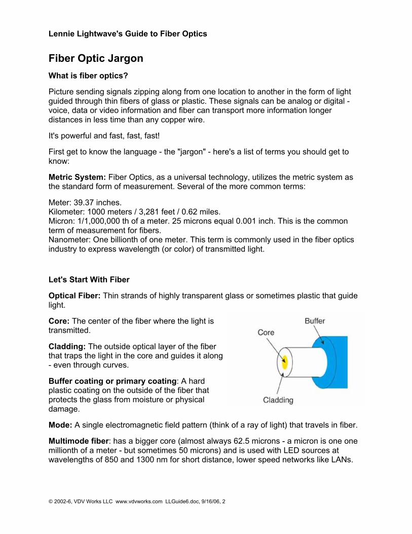
Core: The center of the fiber where the light istransmitted.
Cladding: The outside optical layer of the fiberthat traps the light in the core and guides it along- even through curves.
Buffer coating or primary coating: A hardplastic coating on the outside of the fiber thatprotects the glass from moisture or physicaldamage.
Mode: A single electromagnetic field pattern (think of a ray of light) that travels in fiber.
Multimode fiber: has a bigger core (almost always 62.5 microns - a micron is one onemillionth of a meter - but sometimes 50 microns) and is used with LED sources atwavelengths of 850 and 1300 nm for short distance, lower speed networks like LANs.
Lennie Lightwave's Guide to Fiber Optics
© 2002-6, VDV Works LLC www.vdvworks.com LLGuide6.doc, 9/16/06, 3
Singlemode fiber: has a much smaller core, only about 9 microns, and is used fortelephony and CATV with laser sources at 1300 and 1550 nm. It can go very longdistances at very high speeds.
Both multimode and singlemode fiber have an outside diameter of 125 microns - about5 thousandths of an inch - just slightly larger than a human hair.
Plastic optical fiber (POF): is a large core (about 1mm) multimode fiber that can beused for short, low speed networks. POF is used in consumer HiFi and starting to beused as part of a new standard for car communication systems called MOST (go tohttp://www.mostcooperation.com/)
Terms that describe fiber optic cable:
Cable: Fiber needs protection to survive all the places it gets installed and it's the cablethat provides it. Cables may have from one to hundreds of fibers inside.
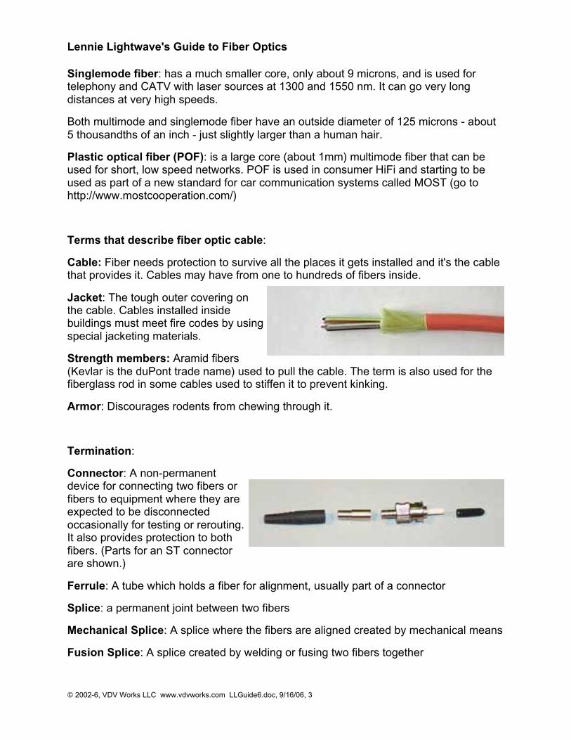
Jacket: The tough outer covering onthe cable. Cables installed insidebuildings must meet fire codes by usingspecial jacketing materials.
Strength members: Aramid fibers(Kevlar is the duPont trade name) used to pull the cable. The term is also used for thefiberglass rod in some cables used to stiffen it to prevent kinking.
Armor: Discourages rodents from chewing through it.
Termination:
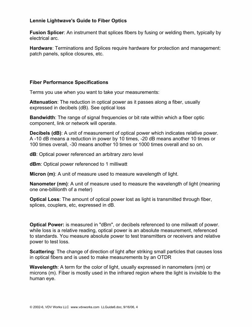
Connector: A non-permanentdevice for connecting two fibers orfibers to equipment where they areexpected to be disconnectedoccasionally for testing or rerouting.It also provides protection to bothfibers. (Parts for an ST connectorare shown.)
Ferrule: A tube which holds a fiber for alignment, usually part of a connector
Splice: a permanent joint between two fibers
Mechanical Splice: A splice where the fibers are aligned created by mechanical means
Fusion Splice: A splice created by welding or fusing two fibers together
Lennie Lightwave's Guide to Fiber Optics
© 2002-6, VDV Works LLC www.vdvworks.com LLGuide6.doc, 9/16/06, 4
Fusion Splicer: An instrument that splices fibers by fusing or welding them, typically byelectrical arc.
Hardware: Terminations and Splices require hardware for protection and management:patch panels, splice closures, etc.
Fiber Performance Specifications
Terms you use when you want to take your measurements:
Attenuation: The reduction in optical power as it passes along a fiber, usuallyexpressed in decibels (dB). See optical loss
Bandwidth: The range of signal frequencies or bit rate within which a fiber opticcomponent, link or network will operate.
Decibels (dB): A unit of measurement of optical power which indicates relative power.A -10 dB means a reduction in power by 10 times, -20 dB means another 10 times or100 times overall, -30 means another 10 times or 1000 times overall and so on.
dB: Optical power referenced an arbitrary zero level
dBm: Optical power referenced to 1 milliwatt
Micron (m): A unit of measure used to measure wavelength of light.
Nanometer (nm): A unit of measure used to measure the wavelength of light (meaningone one-billilonth of a meter)
Optical Loss: The amount of optical power lost as light is transmitted through fiber,splices, couplers, etc, expressed in dB.
Optical Power: is measured in "dBm", or decibels referenced to one miliwatt of power.while loss is a relative reading, optical power is an absolute measurement, referencedto standards. You measure absolute power to test transmitters or receivers and relativepower to test loss.
Scattering: The change of direction of light after striking small particles that causes lossin optical fibers and is used to make measurements by an OTDR
Wavelength: A term for the color of light, usually expressed in nanometers (nm) ormicrons (m). Fiber is mostly used in the infrared region where the light is invisible to thehuman eye.
Lennie Lightwave's Guide to Fiber Optics
© 2002-6, VDV Works LLC www.vdvworks.com LLGuide6.doc, 9/16/06, 5
Terms that describe the tools you will need for installation and termination:
Jacket Slitter or Stripper: A cutter for removing the heavy outside jacket of cables
Fiber Stripper: A precise stripper used to remove the buffer coating of the fiber itself fortermination. There at three types in common use, called by their trade names: "MillerStripper", "No-Nik" and "Micro Strip."
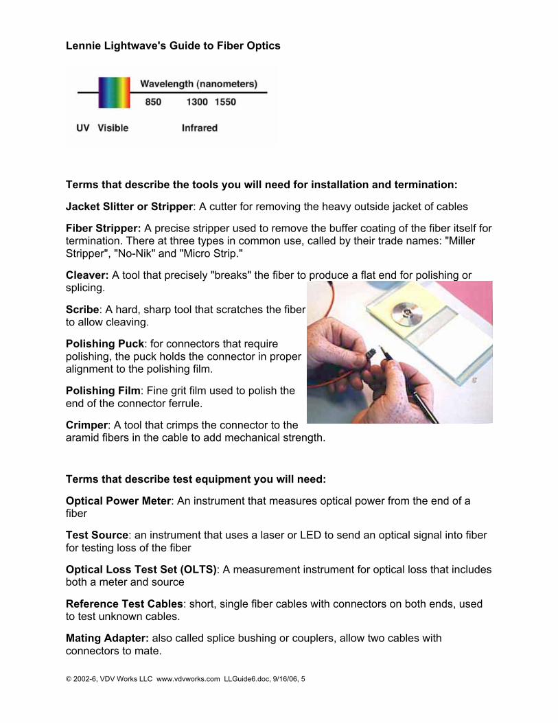
Cleaver: A tool that precisely "breaks" the fiber to produce a flat end for polishing orsplicing.
Scribe: A hard, sharp tool that scratches the fiberto allow cleaving.
Polishing Puck: for connectors that requirepolishing, the puck holds the connector in properalignment to the polishing film.
Polishing Film: Fine grit film used to polish theend of the connector ferrule.
Crimper: A tool that crimps the connector to thearamid fibers in the cable to add mechanical strength.
Terms that describe test equipment you will need:
Optical Power Meter: An instrument that measures optical power from the end of afiber
Test Source: an instrument that uses a laser or LED to send an optical signal into fiberfor testing loss of the fiber
Optical Loss Test Set (OLTS): A measurement instrument for optical loss that includesboth a meter and source
Reference Test Cables: short, single fiber cables with connectors on both ends, usedto test unknown cables.
Mating Adapter: also called splice bushing or couplers, allow two cables withconnectors to mate.
Lennie Lightwave's Guide to Fiber Optics
© 2002-6, VDV Works LLC www.vdvworks.com LLGuide6.doc, 9/16/06, 6
Fiber Tracer: An instrument that allows visual checking of continuity and tracing forcorrect connections
Visual Fault Locator: A device that allows visual tracing and testing of continuity.
Microscope: used to inspect the end surface of a connector for flaws or dirt.
OTDR: An instrument that uses backscattered light to find faults in optical fiber and inferloss from only one end of the cable.
Lennie Lightwave's Guide to Fiber Optics
© 2002-6, VDV Works LLC www.vdvworks.com LLGuide6.doc, 9/16/06, 7
The Basics of Fiber Optics
Getting Started in Fiber Optics - You need tools, test equipment and - most of all -training!
This guide will help you get started by providing very basic information (we will alsopoint you to more advanced studies) and demonstrating that you don't need to break thebank to break into the field.
What is "Fiber Optics"? And a short history.It's the communications technology that works by sending signals down hair thin strandsof glass fiber (and sometimes plastic fiber.) It began about 30 years ago in the R&D labs(Corning, Bell Labs, ITT UK, etc.) and was first installed in Chicago in 1976. By the early1980s, fiber networks connected the major cities on each coast.Bu the mid-80s, fiber was replacing all the telco copper, microwave and satellite links. Inthe 90s, CATV discovered fiber and used it first to enhance the reliability of theirnetworks, a big problem. Along the way, the discovered they could offer phone andInternet service on that same fiber and greatly enlarged their markets.Computers and LANs started using fiber about the same time as the telcos. Industriallinks were among the first as the noise immunity of fiber and its distance capabilitymake it ideal for the factory floor. Mainframe storage networks came next, thepredecessors of today's fiber SANs (storage area networks.)Other applications developed too: aircraft, ship and automobile data busses, CCTV forsecurity, even links for consumer digital stereo!Today fiber optics is either the dominant medium or a logical choice for everycommunication system.
Which Fiber Optics?
Whenever you read an article or talk to someone about fiber optics, you need to knowthe point of view of the writer. Fiber optics, you see, is not all the same. Is the writerdiscussing "outside plant" fiber optics as used in telephone networks or CATV. Or is thearticle about "premises" fiber optics as found in buildings and campuses?Just like "wire" which can mean lots of different things - power, security, HVAC, CCTV,LAN or telephone - fiber optics is not all the same. And this can be a big source ofconfusion to the novice. Lets define our terms.
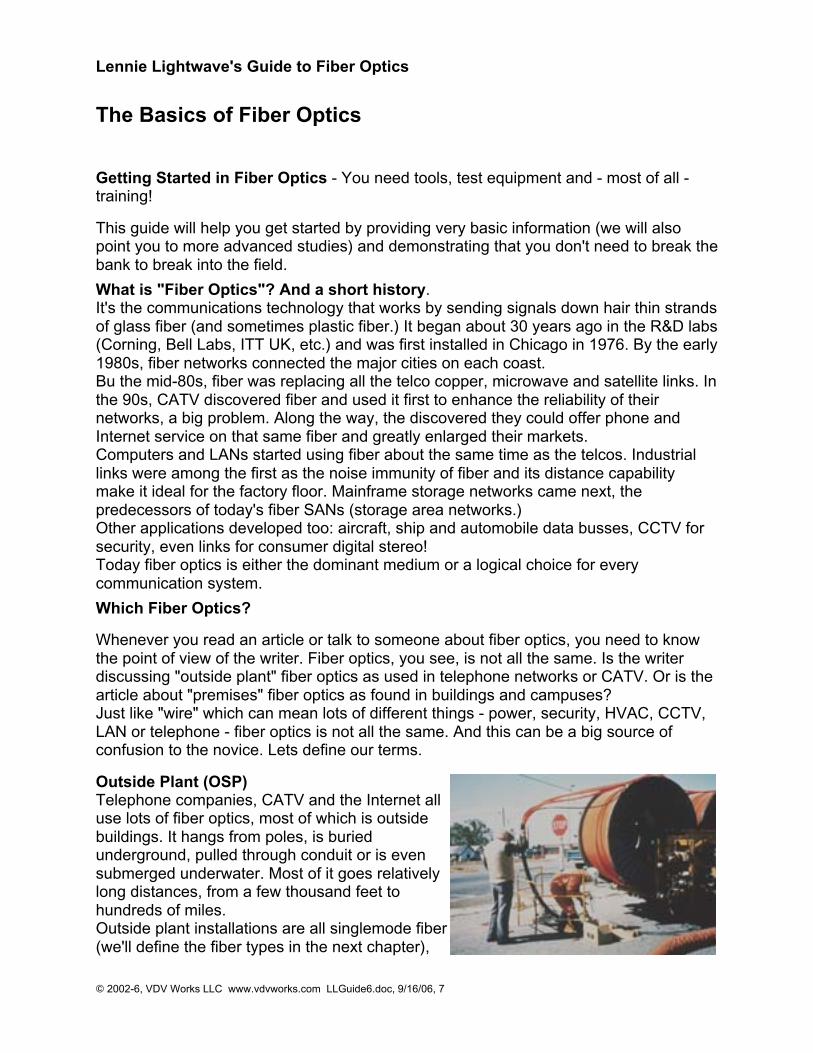
Outside Plant (OSP)Telephone companies, CATV and the Internet alluse lots of fiber optics, most of which is outsidebuildings. It hangs from poles, is buriedunderground, pulled through conduit or is evensubmerged underwater. Most of it goes relativelylong distances, from a few thousand feet tohundreds of miles.Outside plant installations are all singlemode fiber(we'll define the fiber types in the next chapter),
Lennie Lightwave's Guide to Fiber Optics
© 2002-6, VDV Works LLC www.vdvworks.com LLGuide6.doc, 9/16/06, 8
and cables often have very high fiber counts, up to 288 fibers. Cable designs areoptimized for resisting moisture and rodent damage. Installation requires special pullersor plows, and even trailers to carry giant spools of cable.Long distances mean cables are spliced together, since cables are not longer thanabout 4 km (2.5 miles), and most splices are by fusion splicing. Connectors (SC, ST orFC styles) on factory made pigtails are spliced onto the end of the cable. Afterinstallation, every fiber and every splice is tested with an OTDR.If this sounds like big bucks, you are right! The installer usually has a temperaturecontrolled van or trailer for splicing and/or a bucket truck. Investments in fusion splicersand OTDRs can add up to over $100,000 alone.Contractors doing outside plant work are few and far between. Most outside planttelephone installs are done by the telco themselves, while a small number of large,specialized installers do CATV work.
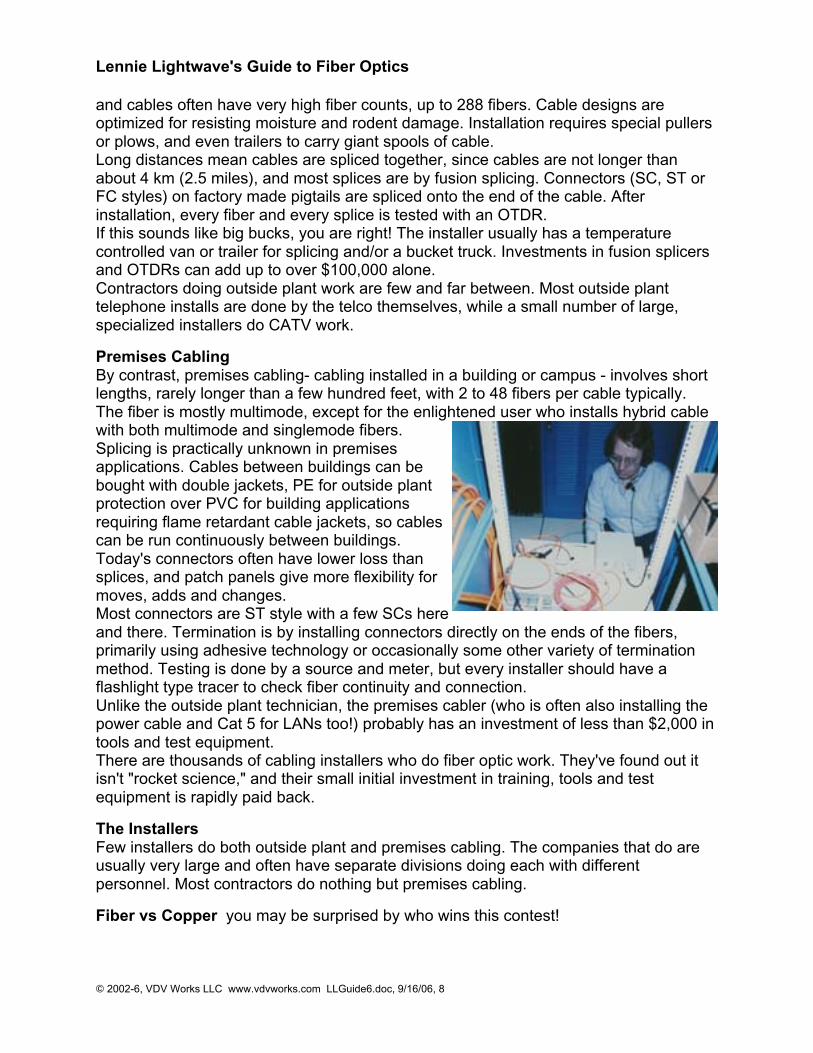
Premises CablingBy contrast, premises cabling- cabling installed in a building or campus - involves shortlengths, rarely longer than a few hundred feet, with 2 to 48 fibers per cable typically.The fiber is mostly multimode, except for the enlightened user who installs hybrid cablewith both multimode and singlemode fibers.Splicing is practically unknown in premisesapplications. Cables between buildings can bebought with double jackets, PE for outside plantprotection over PVC for building applicationsrequiring flame retardant cable jackets, so cablescan be run continuously between buildings.Today's connectors often have lower loss thansplices, and patch panels give more flexibility formoves, adds and changes.Most connectors are ST style with a few SCs hereand there. Termination is by installing connectors directly on the ends of the fibers,primarily using adhesive technology or occasionally some other variety of terminationmethod. Testing is done by a source and meter, but every installer should have aflashlight type tracer to check fiber continuity and connection.Unlike the outside plant technician, the premises cabler (who is often also installing thepower cable and Cat 5 for LANs too!) probably has an investment of less than $2,000 intools and test equipment.There are thousands of cabling installers who do fiber optic work. They've found out itisn't "rocket science," and their small initial investment in training, tools and testequipment is rapidly paid back.
The InstallersFew installers do both outside plant and premises cabling. The companies that do areusually very large and often have separate divisions doing each with differentpersonnel. Most contractors do nothing but premises cabling.
Fiber vs Copper you may be surprised by who wins this contest!
Lennie Lightwave's Guide to Fiber Optics
© 2002-6, VDV Works LLC www.vdvworks.com LLGuide6.doc, 9/16/06, 9
If you are already terminating copper wire then you are well along in learning to installfiber.
Twenty years ago, fiber was just being introduced and required PhD's from Bell Labs toinstall it while copper wire was easy to install. Today it is often the opposite. Becausefiber is so powerful, at today's network speeds fiber is hardly working hard at all and canlook to the future of ten gigabit speeds with confidence. Copper on the other hand, canhandle gigabit Ethernet but only if it is carefully installed and tested with very expensivetest equipment and components. Even the experts have to be very careful because ithas little "headroom".
Also, if you are currently working with copper, you also have to know that LAN coppercable is delicate. It only has a 25 pound pulling tension limit and kinks will ruin the highspeed performance. With fiber - even though it's glass fiber - it has more strength andgreater tolerance to abuse than copper wire. (What do you think gives the strength toyour "fiberglass" boat?)
OK, you might say, I can buy everything you've said so far, but isn't fiber moreexpensive?Telcos and CATV operators use fiber because it's much cheaper. Telcos are now usingfiber instead of copper to directly connect homes! They optimize their network to takeadvantage of fiber's speed and distance advantages. In LANs, you need to follow theEIA/TIA 568 B.3 standard for centralized fiber to optimize the fiber usage, and then itcan be cheaper than copper. How about test equipment? Guess again Fiber optic testequipment costs lots less than Cat 5e/6 testers. See Networks where we will show youhow the setup for a fiber network has some surprising savings.
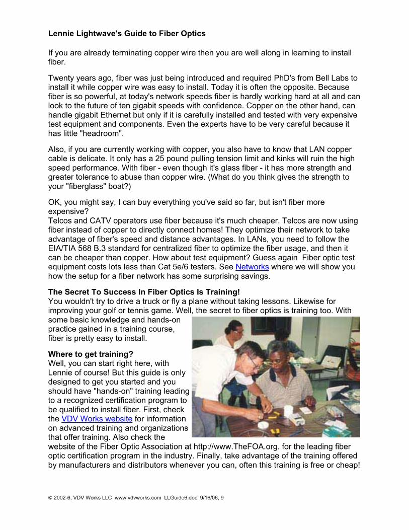
The Secret To Success In Fiber Optics Is Training!You wouldn't try to drive a truck or fly a plane without taking lessons. Likewise forimproving your golf or tennis game. Well, the secret to fiber optics is training too. Withsome basic knowledge and hands-onpractice gained in a training course,fiber is pretty easy to install.
Where to get training?Well, you can start right here, withLennie of course! But this guide is onlydesigned to get you started and youshould have "hands-on" training leadingto a recognized certification program tobe qualified to install fiber. First, checkthe VDV Works website for informationon advanced training and organizationsthat offer training. Also check thewebsite of the Fiber Optic Association at http://www.TheFOA.org. for the leading fiberoptic certification program in the industry. Finally, take advantage of the training offeredby manufacturers and distributors whenever you can, often this training is free or cheap!
Lennie Lightwave's Guide to Fiber Optics
© 2002-6, VDV Works LLC www.vdvworks.com LLGuide6.doc, 9/16/06, 10
StandardsMost of what we call standards are voluntary standards, created by industry groups toinsure product compatibility. They are not "codes" or actual laws that you must follow tobe in compliance with local ordinances.Standards like EIA/TIA 568B ( from the Electronic Industries Alliance/Telecommunications Industry Association) which covers all of the things you need toknow to install a standard premises cabling network are good guidelines for designs, butjust guidelines - they are not mandatory. Standards for fiber optic components andtesting have been set by several groups, but most in the US follow the EIA/TIAdeveloped FOTP's (fiber optic test procedures) for testing. Some of the EIA proceduresare also called OFSTP (optical fiber system test procedures) like OFSTP-14 for theinstalled cable plant.Standards for optical power measurements are set by NIST (the US National Institute ofStandards and Technology) formerly the National Bureau of Standards.The only common mandatory standard is the NEC 770 (National Electrical Code). TheNEC specifies fire prevention standards for fiber optic cables. If a cable doesn't have aNEC rating - don't install it - it won't pass inspection!
A complete listing of the EIA/TIA standards is on the website of The Fiber OpticAssociation. Information on the EIA/TIA standards can be found on the website of mostof he suppliers of structured cabling hardware.
Before we get started - Safety First!
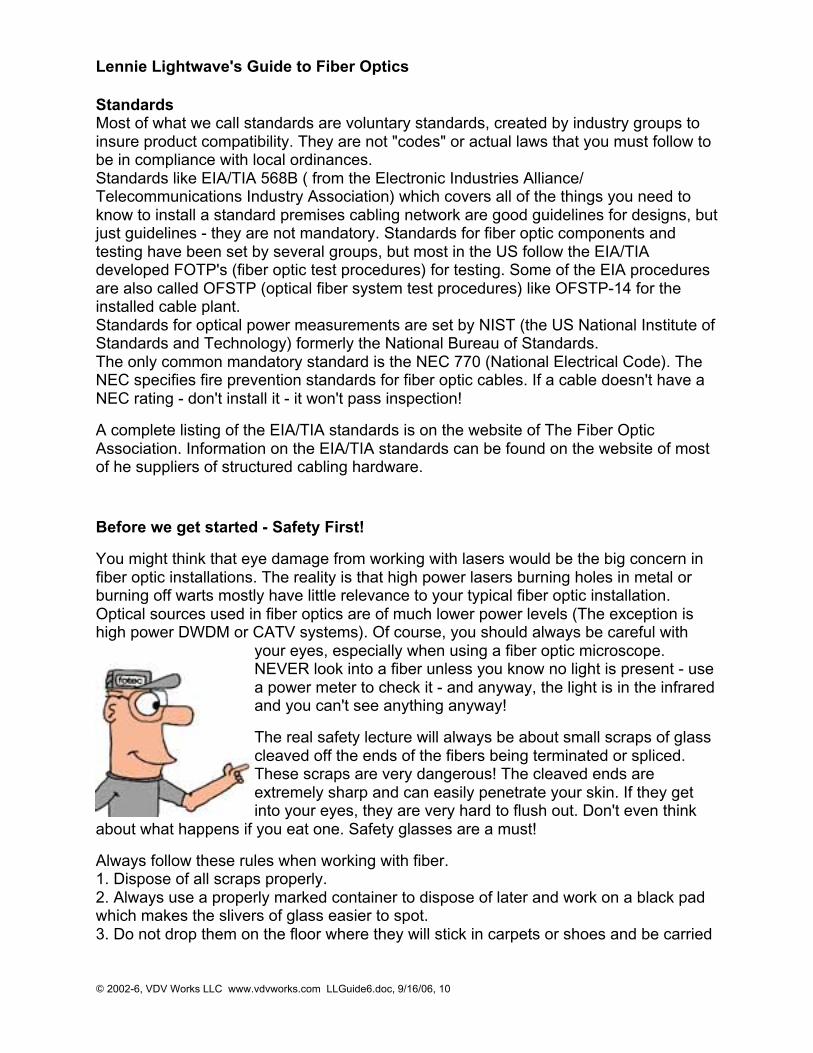
You might think that eye damage from working with lasers would be the big concern infiber optic installations. The reality is that high power lasers burning holes in metal orburning off warts mostly have little relevance to your typical fiber optic installation.Optical sources used in fiber optics are of much lower power levels (The exception ishigh power DWDM or CATV systems). Of course, you should always be careful with
your eyes, especially when using a fiber optic microscope.NEVER look into a fiber unless you know no light is present - usea power meter to check it - and anyway, the light is in the infraredand you can't see anything anyway!
The real safety lecture will always be about small scraps of glasscleaved off the ends of the fibers being terminated or spliced.These scraps are very dangerous! The cleaved ends areextremely sharp and can easily penetrate your skin. If they getinto your eyes, they are very hard to flush out. Don't even think
about what happens if you eat one. Safety glasses are a must!
Always follow these rules when working with fiber.1. Dispose of all scraps properly.2. Always use a properly marked container to dispose of later and work on a black padwhich makes the slivers of glass easier to spot.3. Do not drop them on the floor where they will stick in carpets or shoes and be carried
Lennie Lightwave's Guide to Fiber Optics
© 2002-6, VDV Works LLC www.vdvworks.com LLGuide6.doc, 9/16/06, 11
elsewhere.4. Do not eat or drink anywhere near the work area.
Fiber optic splicing and termination use various chemical adhesives and cleaners aspart of the processes. Follow the instructions for use carefully. Remember, even simpleisopropyl alcohol, used as a cleaner, is flammable.
Zero Tolerance for Dirt
With fiber optics, our tolerance to dirt is near zero. Airborne particles are about the sizeof the core of SM fiber- they absorb lots of light and may scratch connectors if notremoved! Dirt on connectors is the biggest cause of scratches on polished connectorsand high loss measurements!
1.Try to work in a clean area. Avoid working around heating outlets, as they blowdust all over you2. Always keep dust caps on connectors, bulkhead splices, patch panels or anythingelse that is going to have a connection made with it.3. Use lint free pads and isopropyl alcohol to clean the connectors.4. Ferrules on the connectors/cables used for testing will get dirty by scraping off thematerial of the alignment sleeve in the splice bushing - creating a 1-2 dB attenuator.You can see the front edge of the connector ferrule getting black! Use the metal orceramic alignment sleeve bulkheads only for testing.
Lennie Lightwave's Guide to Fiber Optics
© 2002-6, VDV Works LLC www.vdvworks.com LLGuide6.doc, 9/16/06, 12
Fiber
Fiber Specifications
The usual fiber specifications you will see are size, attenuation and bandwidth. Whilemanufacturers have other specs that concern them, like numerical aperture (theacceptance angle of light into the fiber), ovality (how round the fiber is), concentricity ofthe core and cladding, etc., these specs do not affect you.
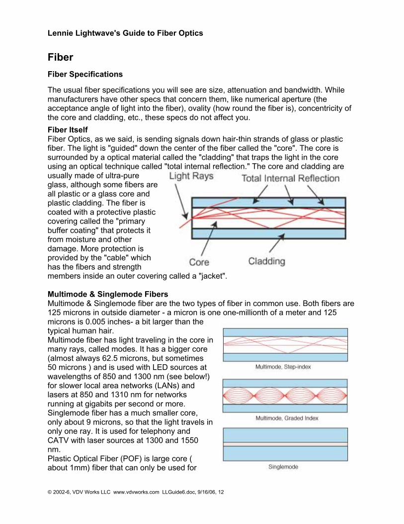
Fiber ItselfFiber Optics, as we said, is sending signals down hair-thin strands of glass or plasticfiber. The light is "guided" down the center of the fiber called the "core". The core issurrounded by a optical material called the "cladding" that traps the light in the coreusing an optical technique called "total internal reflection." The core and cladding areusually made of ultra-pureglass, although some fibers areall plastic or a glass core andplastic cladding. The fiber iscoated with a protective plasticcovering called the "primarybuffer coating" that protects itfrom moisture and otherdamage. More protection isprovided by the "cable" whichhas the fibers and strengthmembers inside an outer covering called a "jacket". Multimode & Singlemode FibersMultimode & Singlemode fiber are the two types of fiber in common use. Both fibers are125 microns in outside diameter - a micron is one one-millionth of a meter and 125microns is 0.005 inches- a bit larger than thetypical human hair.Multimode fiber has light traveling in the core inmany rays, called modes. It has a bigger core(almost always 62.5 microns, but sometimes50 microns ) and is used with LED sources atwavelengths of 850 and 1300 nm (see below!)for slower local area networks (LANs) andlasers at 850 and 1310 nm for networksrunning at gigabits per second or more.Singlemode fiber has a much smaller core,only about 9 microns, so that the light travels inonly one ray. It is used for telephony andCATV with laser sources at 1300 and 1550nm.Plastic Optical Fiber (POF) is large core (about 1mm) fiber that can only be used for
Lennie Lightwave's Guide to Fiber Optics
© 2002-6, VDV Works LLC www.vdvworks.com LLGuide6.doc, 9/16/06, 13
short, low speed networks.
Step index multimode was the first fiber design but is too slow for most uses, due tothe dispersion caused by the different path lengths of the various modes. Step indexfiber is rare - only POF uses a step index design today.
Graded index multimode fiber uses variations in the composition of the glass in thecore to compensate for the different path lengths of the modes. It offers hundreds oftimes more bandwidth than step index fiber - up to about 2 gigahertz.
Singlemode fiber shrinks the core down so small that the light can only travel in oneray. This increases the bandwidth to almost infinity - but it's practically limited to about100,000 gigahertz - that's still a lot!
When It Comes To Fiber, Size MattersFiber, as we said, comes in two types, singlemode and multimode. Except for fibersused in specialty applications, singlemode fiber can be considered as one size andtype. If you deal with long haul telecom customers, you may have to work withmanufacturers on specialty singlemode fibers.
Multimode fibers originally came in several sizes, optimized for various networks andsources, but the data industry standardized on 62.5 core fiber in the mid-80s (62.5/125fiber has a 62.5 micron core and a 125 micron cladding.) Recently, as gigabit and 10gigabit networks have become widely used, an old fiber has been revived. The 50/125fiber was used from the late 70s with lasers for telecom applications before singlemodefiber became available. It offers higher bandwidth with the laser sources used in thegigabit LANs and can go longer distances. While it still represents a smaller volumethan 62.5/125, it is growing.
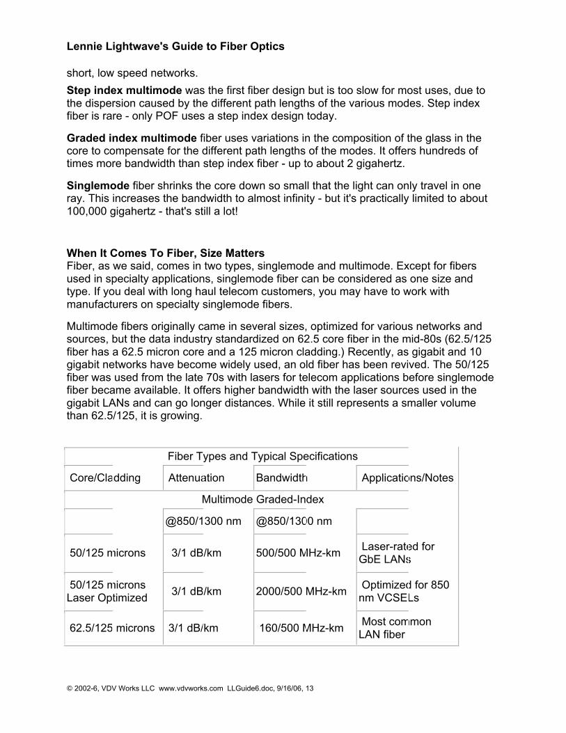
Fiber Types and Typical Specifications
Core/Cladding Attenuation Bandwidth Applications/Notes
Multimode Graded-Index
@850/1300 nm @850/1300 nm
50/125 microns 3/1 dB/km 500/500 MHz-km Laser-rated forGbE LANs
50/125 micronsLaser Optimized
3/1 dB/km 2000/500 MHz-km Optimized for 850nm VCSELs
62.5/125 microns 3/1 dB/km 160/500 MHz-km Most commonLAN fiber
Lennie Lightwave's Guide to Fiber Optics
© 2002-6, VDV Works LLC www.vdvworks.com LLGuide6.doc, 9/16/06, 14
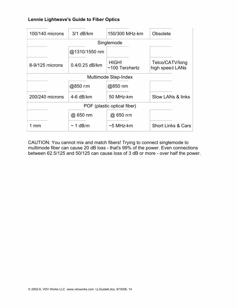
100/140 microns 3/1 dB/km 150/300 MHz-km Obsolete
Singlemode
@1310/1550 nm
8-9/125 microns 0.4/0.25 dB/km HIGH!~100 Terahertz
Telco/CATV/longhigh speed LANs
Multimode Step-Index
@850 nm @850 nm
200/240 microns 4-6 dB/km 50 MHz-km Slow LANs & links
POF (plastic optical fiber)
@ 650 nm @ 650 nm
1 mm ~ 1 dB/m ~5 MHz-km Short Links & Cars
CAUTION: You cannot mix and match fibers! Trying to connect singlemode tomultimode fiber can cause 20 dB loss - that's 99% of the power. Even connectionsbetween 62.5/125 and 50/125 can cause loss of 3 dB or more - over half the power.
Lennie Lightwave's Guide to Fiber Optics
© 2002-6, VDV Works LLC www.vdvworks.com LLGuide6.doc, 9/16/06, 15
Fiber Optic Cables
Fiber optic "cable" refers to the complete assembly of fibers, strength members andjacket. Fiber optic cables come in lots of different types, depending on the number offibers and how and where it will be installed. Choose cable carefully as the choice willaffect how easy it is to install, splice or terminate and, most important, what it will cost!
Choosing a cable - what hazards will it face?
Cable's job is to protect the fibers from the hazards encountered in an installation. Willthe cables be exposed to chemicals or have to withstand a wide temperature range?What about being gnawed on by a woodchuck or prairie dog? Inside buildings, cablesdon't have to be so strong to protect the fibers, but they have to meet all fire codeprovisions. Outside the building, it depends on whether the cable is buried directly,pulled in conduit, strung aerially or whatever.
Your best bet is to contact a few cable manufacturers (two minimum, three preferred)and give them the specs. They will want to know where the cable is going, how manyfibers you need and what kind (singlemode or multimode or both in what we call "hybrid"cables.) You can also have a "composite" cable that includes copper conductors forsignals or power. The cable companies will evaluate your requirements and makesuggestions. Then you can get competitive bids.
Since the plan will call for a certain number of fibers, consider adding spare fibers to thecable - fibers are cheap! That way, you won't be in trouble if you break a fiber or twowhen splicing, breaking-out or terminating fibers. And request the end user considertheir future expansion needs. Most users install lots more fibers than needed, especiallyadding singlemode fiber to multimode fiber cables for campus or backbone applications.
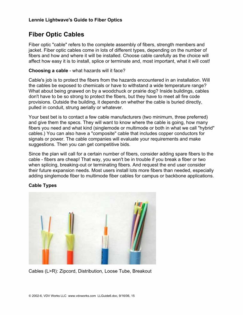
Cable Types
Cables (L>R): Zipcord, Distribution, Loose Tube, Breakout

Lennie Lightwave's Guide to Fiber Optics
© 2002-6, VDV Works LLC www.vdvworks.com LLGuide6.doc, 9/16/06, 16
Simplex and zip cord: Simplex cables are one fiber, tight-buffered (coated with a 900micron buffer over the primary buffer coating) with Kevlar (aramid fiber) strengthmembers and jacketed for indoor use. The jacket is usually 3mm (1/8 in.) diameter.Zipcord is simply two of these joined with a thin web. It's used mostly for patch cord andbackplane applications, but zipcord can also be used for desktop connections.
Distribution cables: They contain several tight-buffered fibers bundled under the samejacket with Kevlar strength members and sometimes fiberglass rod reinforcement tostiffen the cable and prevent kinking. These cables are small in size, and used for short,dry conduit runs, riser and plenum applications. The fibers are double buffered and canbe directly terminated, but because their fibers are not individually reinforced, thesecables need to be broken out with a "breakout box" or terminated inside a patch panelor junction box.
Breakout cables: They are made of several simplex cables bundled together. This is astrong, rugged design, but is larger and more expensive than the distribution cables. Itis suitable for conduit runs, riser and plenum applications. Because each fiber isindividually reinforced, this design allows for quick termination to connectors and doesnot require patch panels or boxes. Breakout cable can be more economic where fibercount isn't too large and distances too long, because is requires so much less labor toterminate.
Loose tube cables: These cables are composed of several fibers together inside asmall plastic tube, which are in turn wound around a central strength member andjacketed, providing a small, high fiber count cable. This type of cable is ideal for outsideplant trunking applications, as it can be made with the loose tubes filled with gel orwater absorbent powder to prevent harm to the fibers from water. It can be used inconduits, strung overhead or buried directly into the ground. Since the fibers have only athin buffer coating, they must be carefully handled and protected to prevent damage.
Ribbon Cable: This cable offers the highest packing density, since all the fibers are laidout in rows, typically of 12 fibers, and laid on top of each other. This way 144 fibers onlyhas a cross section of about 1/4 inch or 6 mm! Some cable designs use a "slotted core"with up to 6 of these 144 fiber ribbon assemblies for 864 fibers in one cable! Since it'soutside plant cable, it's gel-filled for water blocking.
Armored Cable: Cable installed by direct burial in areas where rodents are a problemusually have metal armoring between two jackets to prevent rodent penetration. Thismeans the cable is conductive, so it must be grounded properly.
Aerial cable: Aerial cables are for outside installation on poles. They can be lashed to amessenger or another cable (common in CATV) or have metal or aramid strengthmembers to make them self supporting.
Even More Types Are Available: Every manufacturer has it's own favorites, so it's agood idea to get literature from as many cable makers as possible. And check out thelittle guys; often they can save you a bundle by making special cable just for you, evenin relative small quantities.
Lennie Lightwave's Guide to Fiber Optics
© 2002-6, VDV Works LLC www.vdvworks.com LLGuide6.doc, 9/16/06, 17
Cable Design Criteria
Pulling Strength: Some cable is simply laid into cable trays or ditches, so pull strengthis not too important. But other cable may be pulled thorough 2 km or more of conduit.Even with lots of cable lubricant, pulling tension can be high. Most cables get theirstrength from an aramid fiber (Kevlar is the duPont trade name), a unique polymer fiberthat is very strong but does not stretch - so pulling on it will not stress the othercomponents in the cable. The simplest simplex cable has a pull strength of 100-200pounds, while outside plant cable may have a specification of over 800 pounds.
Water Protection: Outdoors, every cable must be protected from water or moisture. Itstarts with a moisture resistant jacket, usually PE (polyethylene), and a filling of water-blocking material. The usual way is to flood the cable with a water-blocking gel. It'seffective but messy - requiring a gel remover (use the commercial stuff - it's best- -butbottled lemon juice works in a pinch!). A newer alternative is dry water blocking using amiracle powder - the stuff developed to absorb moisture in disposable diapers. Checkwith your cable supplier to see if they offer it.
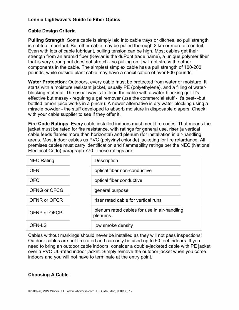
Fire Code Ratings: Every cable installed indoors must meet fire codes. That means thejacket must be rated for fire resistance, with ratings for general use, riser (a verticalcable feeds flames more than horizontal) and plenum (for installation in air-handlingareas. Most indoor cables us PVC (polyvinyl chloride) jacketing for fire retardance. Allpremises cables must carry identification and flammability ratings per the NEC (NationalElectrical Code) paragraph 770. These ratings are:
NEC Rating Description
OFN optical fiber non-conductive
OFC optical fiber conductive
OFNG or OFCG general purpose
OFNR or OFCR riser rated cable for vertical runs
OFNP or OFCP plenum rated cables for use in air-handlingplenums
OFN-LS low smoke density
Cables without markings should never be installed as they will not pass inspections!Outdoor cables are not fire-rated and can only be used up to 50 feet indoors. If youneed to bring an outdoor cable indoors, consider a double-jacketed cable with PE jacketover a PVC UL-rated indoor jacket. Simply remove the outdoor jacket when you comeindoors and you will not have to terminate at the entry point.
Choosing A Cable
Lennie Lightwave's Guide to Fiber Optics
© 2002-6, VDV Works LLC www.vdvworks.com LLGuide6.doc, 9/16/06, 18
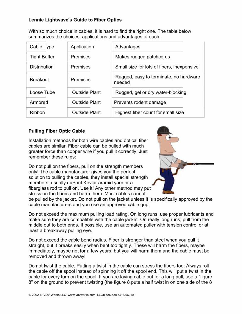
With so much choice in cables, it is hard to find the right one. The table belowsummarizes the choices, applications and advantages of each.
Cable Type Application Advantages
Tight Buffer Premises Makes rugged patchcords
Distribution Premises Small size for lots of fibers, inexpensive
Breakout Premises Rugged, easy to terminate, no hardwareneeded
Loose Tube Outside Plant Rugged, gel or dry water-blocking
Armored Outside Plant Prevents rodent damage
Ribbon Outside Plant Highest fiber count for small size
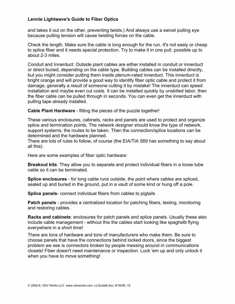
Pulling Fiber Optic Cable
Installation methods for both wire cables and optical fibercables are similar. Fiber cable can be pulled with muchgreater force than copper wire if you pull it correctly. Justremember these rules:
Do not pull on the fibers, pull on the strength membersonly! The cable manufacturer gives you the perfectsolution to pulling the cables, they install special strengthmembers, usually duPont Kevlar aramid yarn or afiberglass rod to pull on. Use it! Any other method may putstress on the fibers and harm them. Most cables cannotbe pulled by the jacket. Do not pull on the jacket unless it is specifically approved by thecable manufacturers and you use an approved cable grip.
Do not exceed the maximum pulling load rating. On long runs, use proper lubricants andmake sure they are compatible with the cable jacket. On really long runs, pull from themiddle out to both ends. If possible, use an automated puller with tension control or atleast a breakaway pulling eye.
Do not exceed the cable bend radius. Fiber is stronger than steel when you pull itstraight, but it breaks easily when bent too tightly. These will harm the fibers, maybeimmediately, maybe not for a few years, but you will harm them and the cable must beremoved and thrown away!
Do not twist the cable. Putting a twist in the cable can stress the fibers too. Always rollthe cable off the spool instead of spinning it off the spool end. This will put a twist in thecable for every turn on the spool! If you are laying cable out for a long pull, use a "figure8" on the ground to prevent twisting (the figure 8 puts a half twist in on one side of the 8
Lennie Lightwave's Guide to Fiber Optics
© 2002-6, VDV Works LLC www.vdvworks.com LLGuide6.doc, 9/16/06, 19
and takes it out on the other, preventing twists.) And always use a swivel pulling eyebecause pulling tension will cause twisting forces on the cable.
Check the length. Make sure the cable is long enough for the run. It's not easly or cheapto splice fiber and it needs special protection. Try to make it in one pull, possible up toabout 2-3 miles.
Conduit and Innerduct: Outside plant cables are either installed in conduit or innerductor direct buried, depending on the cable type. Building cables can be installed directly,but you might consider putting them inside plenum-rated innerduct. This innerduct isbright orange and will provide a good way to identify fiber optic cable and protect it fromdamage, generally a result of someone cutting it by mistake! The innerduct can speedinstallation and maybe even cut costs. It can be installed quickly by unskilled labor, thenthe fiber cable can be pulled through in seconds. You can even get the innerduct withpulling tape already installed.
Cable Plant Hardware - fitting the pieces of the puzzle together!
These various enclosures, cabinets, racks and panels are used to protect and organizesplice and termination points. The network designer should know the type of network,support systems, the routes to be taken. Then the connection/splice locations can bedetermined and the hardware planned.There are lots of rules to follow, of course (the EIA/TIA 569 has something to say aboutall this).
Here are some examples of fiber optic hardware:
Breakout kits: They allow you to separate and protect individual fibers in a loose tubecable so it can be terminated.
Splice enclosures - for long cable runs outside, the point where cables are spliced,sealed up and buried in the ground, put in a vault of some kind or hung off a pole.
Splice panels- connect individual fibers from cables to pigtails
Patch panels - provides a centralized location for patching fibers, testing, monitoringand restoring cables.
Racks and cabinets: enclosures for patch panels and splice panels. Usually these alsoinclude cable management - without this the cables start looking like spaghetti flyingeverywhere in a short time!
There are tons of hardware and tons of manufacturers who make them. Be sure tochoose panels that have the connections behind locked doors, since the biggestproblem we see is connectors broken by people messing around in communicationsclosets! Fiber doesn't need maintenance or inspection. Lock 'em up and only unlock itwhen you have to move something!
Lennie Lightwave's Guide to Fiber Optics
© 2002-6, VDV Works LLC www.vdvworks.com LLGuide6.doc, 9/16/06, 20
Termination
We terminate fiber optic cable two ways - with connectors that can mate two fibers tocreate a temporary joint and/or connect the fiber to a piece of network gear or withsplices which create a permanent joint between the two fibers. These terminations mustbe of the right style, installed in a manner that makes them have little light loss andprotected against dirt or damage in use.No area of fiber optics has been given greater attention than termination. Manufacturershave come up with over 80 styles of connectors and and about a dozen ways to installthem. There are two types of splices and many ways of implementing the splice.Fortunately for me and you, only a few types are used most applications.Different connectors and splice termination procedures are used for singlemode andmultimode connectors, so make sure you know what the fiber will be before you specifyconnectors or splices!
Connectors
We'll start our section on termination by considering connectors. Since fiber optictechnology was introduced in the late 70s, numerous connector styles have beendeveloped. Each new design was meant to offer better performance (less light loss andback reflection), easier and/or termination and lower cost. Of course, the marketplacedetermines which connectors are ultimately successful.
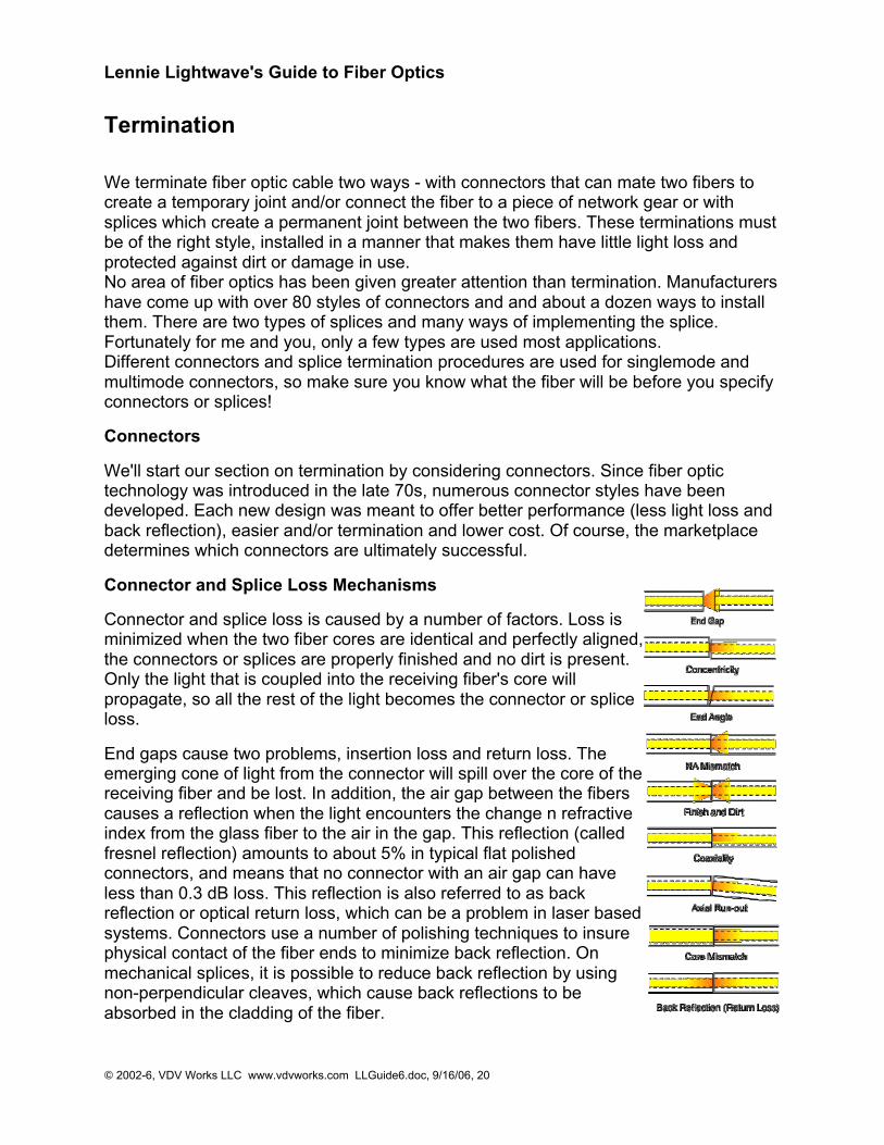
Connector and Splice Loss Mechanisms
Connector and splice loss is caused by a number of factors. Loss isminimized when the two fiber cores are identical and perfectly aligned,the connectors or splices are properly finished and no dirt is present.Only the light that is coupled into the receiving fiber's core willpropagate, so all the rest of the light becomes the connector or spliceloss.
End gaps cause two problems, insertion loss and return loss. Theemerging cone of light from the connector will spill over the core of thereceiving fiber and be lost. In addition, the air gap between the fiberscauses a reflection when the light encounters the change n refractiveindex from the glass fiber to the air in the gap. This reflection (calledfresnel reflection) amounts to about 5% in typical flat polishedconnectors, and means that no connector with an air gap can haveless than 0.3 dB loss. This reflection is also referred to as backreflection or optical return loss, which can be a problem in laser basedsystems. Connectors use a number of polishing techniques to insurephysical contact of the fiber ends to minimize back reflection. Onmechanical splices, it is possible to reduce back reflection by usingnon-perpendicular cleaves, which cause back reflections to beabsorbed in the cladding of the fiber.
Lennie Lightwave's Guide to Fiber Optics
© 2002-6, VDV Works LLC www.vdvworks.com LLGuide6.doc, 9/16/06, 21
The end finish of the fiber must be properly polished to minimize loss. A rough surfacewill scatter light and dirt can scatter and absorb light. Since the optical fiber is so small,typical airborne dirt can be a major source of loss. Whenever connectors are notterminated, they should be covered to protect the end of the ferrule from dirt. Oneshould never touch the end of the ferrule, since the oils on one's skin causes the fiber toattract dirt. Before connection and testing, it is advisable to clean connectors with lint-free wipes moistened with isopropyl alcohol.
Two sources of loss are directional; numerical aperture (NA) and core diameter.Differences in these two will create connections that have different losses depending onthe direction of light propagation. Light from a fiber with a larger NA will be moresensitive to angularity and end gap, so transmission from a fiber of larger NA to one ofsmaller NA will be higher loss than the reverse. Likewise, light from a larger fiber willhave high loss coupled to a fiber of smaller diameter, while one can couple a smalldiameter fiber to a large diameter fiber with minimal loss, since it is much less sensitiveto end gap or lateral offset.
These fiber mismatches occur for two reasons. The occasional need to interconnect twodissimilar fibers and production variances in fibers of the same nominal dimensions.With two multimode fibers in usage today and two others which have been usedoccasionally in the past and several types of singlemode fiber in use, it is possible tosometimes have to connect dissimilar fibers or use systems designed for one fiber onanother. Some system manufacturers provide guidelines on using various fibers, somedon't. If you connect a smaller fiber to a larger one, the coupling losses will be minimal,often only the fresnel loss (about 0.3 dB). But connecting larger fibers to smaller onesresults in substantial losses, not only due to the smaller cores size, but also the smallerNA of most small core fibers.
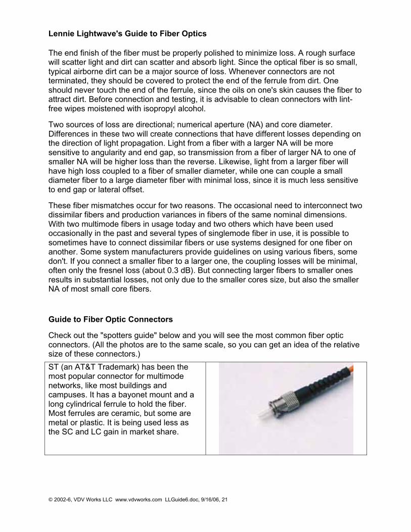
Guide to Fiber Optic Connectors
Check out the "spotters guide" below and you will see the most common fiber opticconnectors. (All the photos are to the same scale, so you can get an idea of the relativesize of these connectors.)
ST (an AT&T Trademark) has been themost popular connector for multimodenetworks, like most buildings andcampuses. It has a bayonet mount and along cylindrical ferrule to hold the fiber.Most ferrules are ceramic, but some aremetal or plastic. It is being used less asthe SC and LC gain in market share.
Lennie Lightwave's Guide to Fiber Optics
© 2002-6, VDV Works LLC www.vdvworks.com LLGuide6.doc, 9/16/06, 22
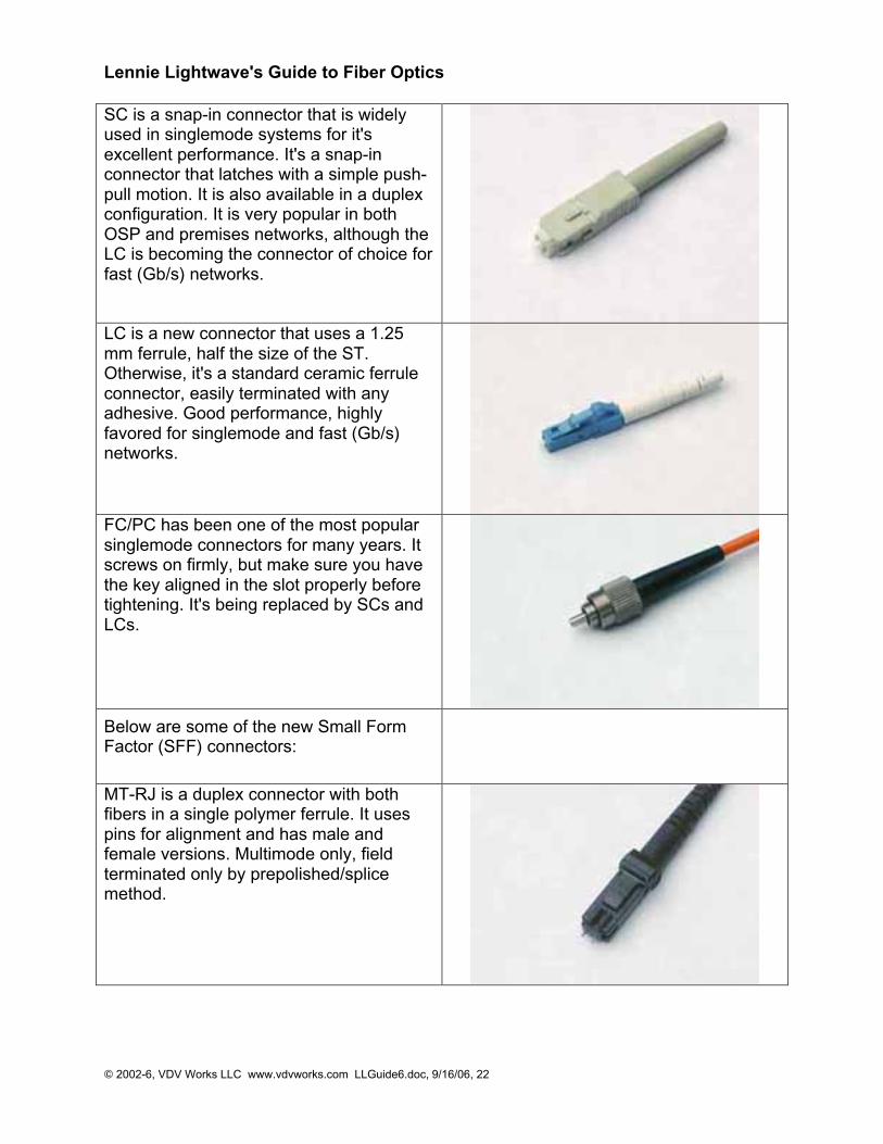
SC is a snap-in connector that is widelyused in singlemode systems for it'sexcellent performance. It's a snap-inconnector that latches with a simple push-pull motion. It is also available in a duplexconfiguration. It is very popular in bothOSP and premises networks, although theLC is becoming the connector of choice forfast (Gb/s) networks.
LC is a new connector that uses a 1.25mm ferrule, half the size of the ST.Otherwise, it's a standard ceramic ferruleconnector, easily terminated with anyadhesive. Good performance, highlyfavored for singlemode and fast (Gb/s)networks.
FC/PC has been one of the most popularsinglemode connectors for many years. Itscrews on firmly, but make sure you havethe key aligned in the slot properly beforetightening. It's being replaced by SCs andLCs.
Below are some of the new Small FormFactor (SFF) connectors:
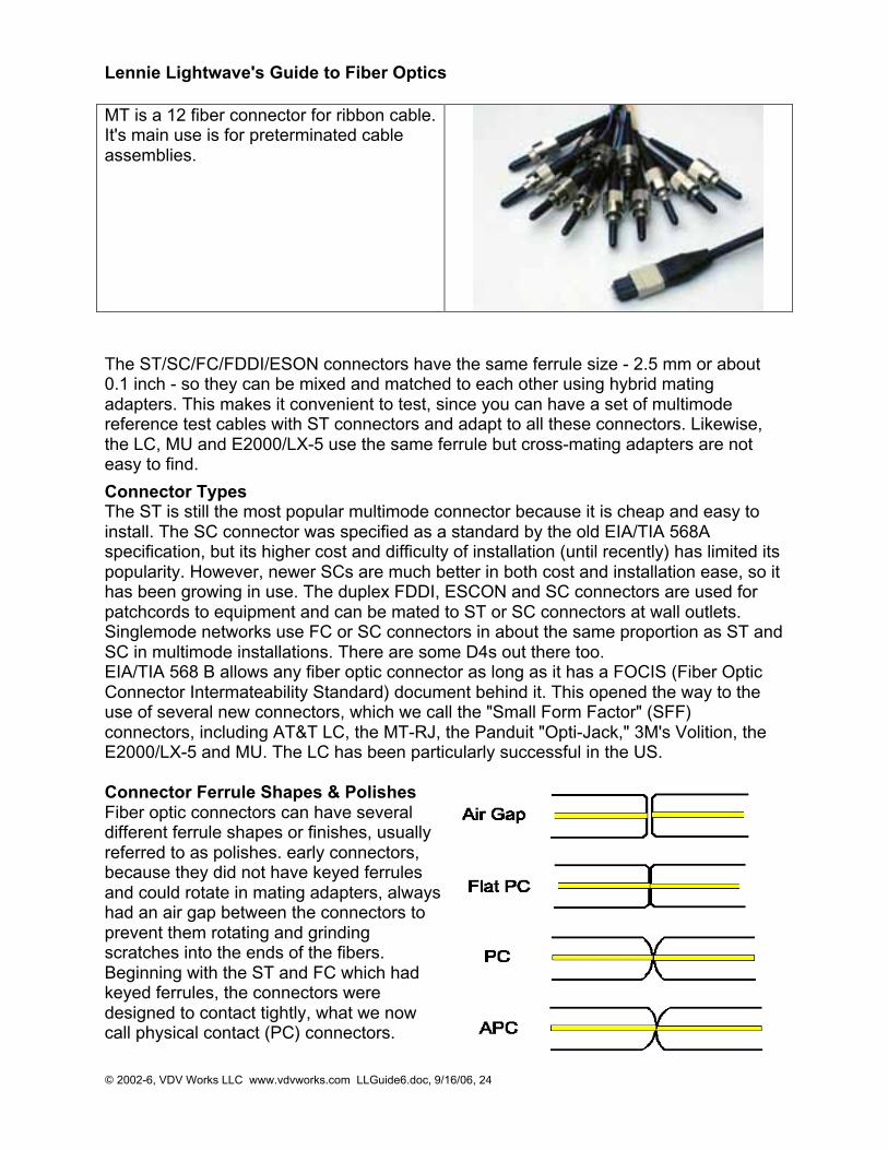
MT-RJ is a duplex connector with bothfibers in a single polymer ferrule. It usespins for alignment and has male andfemale versions. Multimode only, fieldterminated only by prepolished/splicemethod.

Lennie Lightwave's Guide to Fiber Optics
© 2002-6, VDV Works LLC www.vdvworks.com LLGuide6.doc, 9/16/06, 23
Opti-Jack is a neat, rugged duplexconnector cleverly designed around twoST-type ferrules in a package the size of aRJ-45. It has male and female (plug andjack) versions.
Volition is a slick, inexpensive duplexconnector that uses no ferrule at all. Italigns fibers in a V-groove like a splice.Plug and jack versions, but field terminatejacks only.LX-5 is like a LC but with a shutter overthe end of the fiber.
MU looks a miniature SC with a 1.25 mmferrule. It's more popular in Japan.
Lennie Lightwave's Guide to Fiber Optics
© 2002-6, VDV Works LLC www.vdvworks.com LLGuide6.doc, 9/16/06, 24
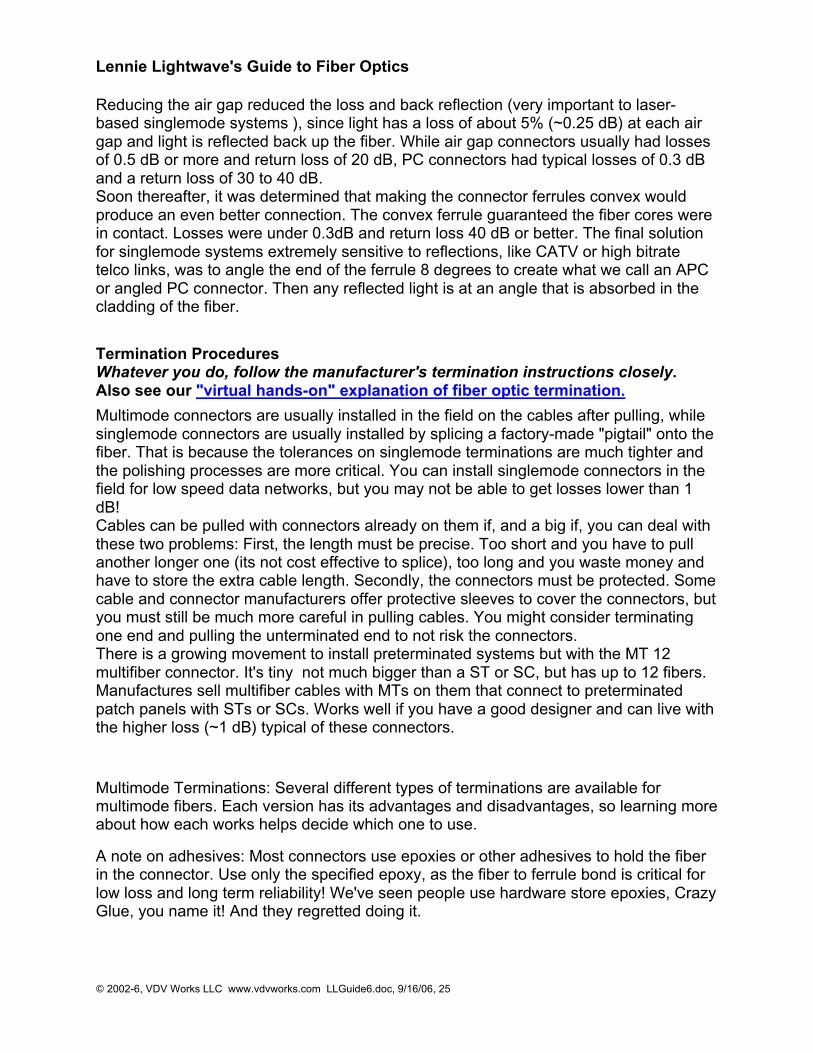
MT is a 12 fiber connector for ribbon cable.It's main use is for preterminated cableassemblies.
The ST/SC/FC/FDDI/ESON connectors have the same ferrule size - 2.5 mm or about0.1 inch - so they can be mixed and matched to each other using hybrid matingadapters. This makes it convenient to test, since you can have a set of multimodereference test cables with ST connectors and adapt to all these connectors. Likewise,the LC, MU and E2000/LX-5 use the same ferrule but cross-mating adapters are noteasy to find.
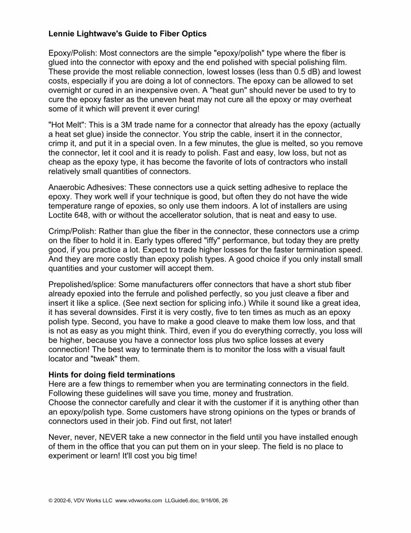
Connector TypesThe ST is still the most popular multimode connector because it is cheap and easy toinstall. The SC connector was specified as a standard by the old EIA/TIA 568Aspecification, but its higher cost and difficulty of installation (until recently) has limited itspopularity. However, newer SCs are much better in both cost and installation ease, so ithas been growing in use. The duplex FDDI, ESCON and SC connectors are used forpatchcords to equipment and can be mated to ST or SC connectors at wall outlets.Singlemode networks use FC or SC connectors in about the same proportion as ST andSC in multimode installations. There are some D4s out there too.EIA/TIA 568 B allows any fiber optic connector as long as it has a FOCIS (Fiber OpticConnector Intermateability Standard) document behind it. This opened the way to theuse of several new connectors, which we call the "Small Form Factor" (SFF)connectors, including AT&T LC, the MT-RJ, the Panduit "Opti-Jack," 3M's Volition, theE2000/LX-5 and MU. The LC has been particularly successful in the US. Connector Ferrule Shapes & PolishesFiber optic connectors can have severaldifferent ferrule shapes or finishes, usuallyreferred to as polishes. early connectors,because they did not have keyed ferrulesand could rotate in mating adapters, alwayshad an air gap between the connectors toprevent them rotating and grindingscratches into the ends of the fibers.Beginning with the ST and FC which hadkeyed ferrules, the connectors weredesigned to contact tightly, what we nowcall physical contact (PC) connectors.
Lennie Lightwave's Guide to Fiber Optics
© 2002-6, VDV Works LLC www.vdvworks.com LLGuide6.doc, 9/16/06, 25
Reducing the air gap reduced the loss and back reflection (very important to laser-based singlemode systems ), since light has a loss of about 5% (~0.25 dB) at each airgap and light is reflected back up the fiber. While air gap connectors usually had lossesof 0.5 dB or more and return loss of 20 dB, PC connectors had typical losses of 0.3 dBand a return loss of 30 to 40 dB.Soon thereafter, it was determined that making the connector ferrules convex wouldproduce an even better connection. The convex ferrule guaranteed the fiber cores werein contact. Losses were under 0.3dB and return loss 40 dB or better. The final solutionfor singlemode systems extremely sensitive to reflections, like CATV or high bitratetelco links, was to angle the end of the ferrule 8 degrees to create what we call an APCor angled PC connector. Then any reflected light is at an angle that is absorbed in thecladding of the fiber.
Termination ProceduresWhatever you do, follow the manufacturer's termination instructions closely.Also see our "virtual hands-on" explanation of fiber optic termination.
Multimode connectors are usually installed in the field on the cables after pulling, whilesinglemode connectors are usually installed by splicing a factory-made "pigtail" onto thefiber. That is because the tolerances on singlemode terminations are much tighter andthe polishing processes are more critical. You can install singlemode connectors in thefield for low speed data networks, but you may not be able to get losses lower than 1dB!Cables can be pulled with connectors already on them if, and a big if, you can deal withthese two problems: First, the length must be precise. Too short and you have to pullanother longer one (its not cost effective to splice), too long and you waste money andhave to store the extra cable length. Secondly, the connectors must be protected. Somecable and connector manufacturers offer protective sleeves to cover the connectors, butyou must still be much more careful in pulling cables. You might consider terminatingone end and pulling the unterminated end to not risk the connectors.There is a growing movement to install preterminated systems but with the MT 12multifiber connector. It's tiny not much bigger than a ST or SC, but has up to 12 fibers.Manufactures sell multifiber cables with MTs on them that connect to preterminatedpatch panels with STs or SCs. Works well if you have a good designer and can live withthe higher loss (~1 dB) typical of these connectors.
Multimode Terminations: Several different types of terminations are available formultimode fibers. Each version has its advantages and disadvantages, so learning moreabout how each works helps decide which one to use.
A note on adhesives: Most connectors use epoxies or other adhesives to hold the fiberin the connector. Use only the specified epoxy, as the fiber to ferrule bond is critical forlow loss and long term reliability! We've seen people use hardware store epoxies, CrazyGlue, you name it! And they regretted doing it.
Lennie Lightwave's Guide to Fiber Optics
© 2002-6, VDV Works LLC www.vdvworks.com LLGuide6.doc, 9/16/06, 26
Epoxy/Polish: Most connectors are the simple "epoxy/polish" type where the fiber isglued into the connector with epoxy and the end polished with special polishing film.These provide the most reliable connection, lowest losses (less than 0.5 dB) and lowestcosts, especially if you are doing a lot of connectors. The epoxy can be allowed to setovernight or cured in an inexpensive oven. A "heat gun" should never be used to try tocure the epoxy faster as the uneven heat may not cure all the epoxy or may overheatsome of it which will prevent it ever curing!
"Hot Melt": This is a 3M trade name for a connector that already has the epoxy (actuallya heat set glue) inside the connector. You strip the cable, insert it in the connector,crimp it, and put it in a special oven. In a few minutes, the glue is melted, so you removethe connector, let it cool and it is ready to polish. Fast and easy, low loss, but not ascheap as the epoxy type, it has become the favorite of lots of contractors who installrelatively small quantities of connectors.
Anaerobic Adhesives: These connectors use a quick setting adhesive to replace theepoxy. They work well if your technique is good, but often they do not have the widetemperature range of epoxies, so only use them indoors. A lot of installers are usingLoctite 648, with or without the accellerator solution, that is neat and easy to use.
Crimp/Polish: Rather than glue the fiber in the connector, these connectors use a crimpon the fiber to hold it in. Early types offered "iffy" performance, but today they are prettygood, if you practice a lot. Expect to trade higher losses for the faster termination speed.And they are more costly than epoxy polish types. A good choice if you only install smallquantities and your customer will accept them.
Prepolished/splice: Some manufacturers offer connectors that have a short stub fiberalready epoxied into the ferrule and polished perfectly, so you just cleave a fiber andinsert it like a splice. (See next section for splicing info.) While it sound like a great idea,it has several downsides. First it is very costly, five to ten times as much as an epoxypolish type. Second, you have to make a good cleave to make them low loss, and thatis not as easy as you might think. Third, even if you do everything correctly, you loss willbe higher, because you have a connector loss plus two splice losses at everyconnection! The best way to terminate them is to monitor the loss with a visual faultlocator and "tweak" them.
Hints for doing field terminationsHere are a few things to remember when you are terminating connectors in the field.Following these guidelines will save you time, money and frustration.Choose the connector carefully and clear it with the customer if it is anything other thanan epoxy/polish type. Some customers have strong opinions on the types or brands ofconnectors used in their job. Find out first, not later!
Never, never, NEVER take a new connector in the field until you have installed enoughof them in the office that you can put them on in your sleep. The field is no place toexperiment or learn! It'll cost you big time!
Lennie Lightwave's Guide to Fiber Optics
© 2002-6, VDV Works LLC www.vdvworks.com LLGuide6.doc, 9/16/06, 27
Have the right tools for the job. Make sure you have the proper tools and they are ingood shape before you head out for the job. This includes all the termination tools,cable tools and test equipment. Do you know your test cables are good? Without that,you will test good terminations as bad every time. More and more installers are owningtheir own tools like auto mechanics, saying that is the only way to make sure the toolsare properly cared for.Dust and dirt are your enemies. It's very hard to terminate or splice in a dusty place. Tryto work in the cleanest possible location. Use lint-free wipes (not cotton swaps or ragsmade from old T-shirts!) to clean every connector before connecting or testing it. Don'twork under heating vents, as they are blowing dirt down on you continuously.Don't overpolish. Contrary to common sense, too much polishing is just as bad as toolittle. The ceramic ferrule in most of today's connector is much harder than the glassfiber. Polish too much and you create a concave fiber surface, increasing the loss. Afew swipes is all it takes.Remember singlemode fiber requires different connectors and polishing techniques.Most SM fiber is terminated by splicing on a preterminated pigtail, but you can put SMconnectors on in the field if you know what you are doing. Expect much higher loss,approaching 1 dB and high back reflections, so don't try it for anything but datanetworks, not telco or CATV.Change polishing film regularly. Polishing builds up residue and dirt on the film that cancause problems after too many connectors and cause poor end finish. Check themanufacturers' specs.Put covers on connectors and patch panels when not in use. Keep them covered tokeep them clean.Inspect and test, then document. It is very hard to troubleshoot cables when you don'tknow how long they are, where they go or how they tested originally! So keep goodrecords, smart users require it and expect to pay extra for good records.
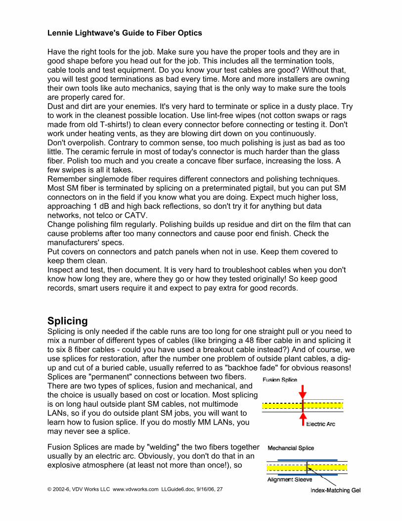
SplicingSplicing is only needed if the cable runs are too long for one straight pull or you need tomix a number of different types of cables (like bringing a 48 fiber cable in and splicing itto six 8 fiber cables - could you have used a breakout cable instead?) And of course, weuse splices for restoration, after the number one problem of outside plant cables, a dig-up and cut of a buried cable, usually referred to as "backhoe fade" for obvious reasons!Splices are "permanent" connections between two fibers.There are two types of splices, fusion and mechanical, andthe choice is usually based on cost or location. Most splicingis on long haul outside plant SM cables, not multimodeLANs, so if you do outside plant SM jobs, you will want tolearn how to fusion splice. If you do mostly MM LANs, youmay never see a splice.
Fusion Splices are made by "welding" the two fibers togetherusually by an electric arc. Obviously, you don't do that in anexplosive atmosphere (at least not more than once!), so
Lennie Lightwave's Guide to Fiber Optics
© 2002-6, VDV Works LLC www.vdvworks.com LLGuide6.doc, 9/16/06, 28
fusion splicing is usually done above ground in a truck or trailer set up for the purpose.Good fusion splicers cost $15,000 to $40,000, but the splices only cost a few dollarseach. Today's singlemode fusion splicers are automated and you have a hard timemaking a bad splice. The biggest application is singlemode fibers in outside plantinstallations.
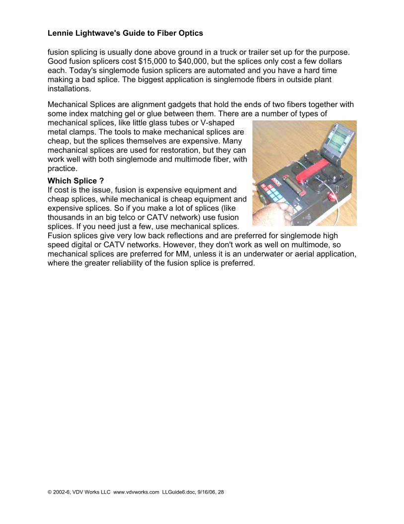
Mechanical Splices are alignment gadgets that hold the ends of two fibers together withsome index matching gel or glue between them. There are a number of types ofmechanical splices, like little glass tubes or V-shapedmetal clamps. The tools to make mechanical splices arecheap, but the splices themselves are expensive. Manymechanical splices are used for restoration, but they canwork well with both singlemode and multimode fiber, withpractice.
Which Splice ?If cost is the issue, fusion is expensive equipment andcheap splices, while mechanical is cheap equipment andexpensive splices. So if you make a lot of splices (likethousands in an big telco or CATV network) use fusionsplices. If you need just a few, use mechanical splices.Fusion splices give very low back reflections and are preferred for singlemode highspeed digital or CATV networks. However, they don't work as well on multimode, somechanical splices are preferred for MM, unless it is an underwater or aerial application,where the greater reliability of the fusion splice is preferred.
Lennie Lightwave's Guide to Fiber Optics
© 2002-6, VDV Works LLC www.vdvworks.com LLGuide6.doc, 9/16/06, 29
Fiber Optic NetworksIn the telcos, singlemode fiber is used to connect long distance switches, central officesand SLCs (subscriber loop carriers, small switches in pedestals in subdivisions or officeparks or in the basement of a larger building). Practically every telco's network is nowfiber optics except the connection to the home. Fiber to the home (FTTH) is now costeffective - especially since most homes want the high speed services that would justifyfiber optics. Look for FTTH first in new home construction.CATV companies "overbuild" with fiber. They lash fiber cable onto the aerial "hardline"coax used for the rest of the network or pull it in the same conduit underground. Thefiber allows them to break their network into smaller service areas that prevent largenumbers of customers from being affected in an outage, making for better service andcustomer relations. The fiber also gives them a return path which they use for Internetand telephone connections, increasing their revenue potential.LANs (local area networks) use fiber optics primarily in the backbone but increasingly tothe desk. The LAN backbone often needs longer distance than copper cable (Cat5/5e/6) can provide and of course, the fiber offers higher bandwidth for futureexpansion. Most large corporate LANs use fiber backbones with copper wire to thedesktop. Fiber to the desk can be cost effective if properly designed.Lots of other networks use fiber. CCTV is often on fiber for it's distance capability.Industrial plants use lots of fiber or distance and noise immunity. Utilities use it fornetwork management, liking its immunity to noise also. The military uses it because it'shard to tap or jam. Airplanes use it for that reason too, but also like the lighter weight offiber.
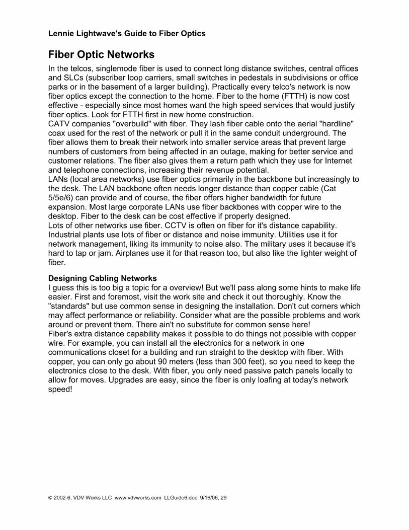
Designing Cabling NetworksI guess this is too big a topic for a overview! But we'll pass along some hints to make lifeeasier. First and foremost, visit the work site and check it out thoroughly. Know the"standards" but use common sense in designing the installation. Don't cut corners whichmay affect performance or reliability. Consider what are the possible problems and workaround or prevent them. There ain't no substitute for common sense here!Fiber's extra distance capability makes it possible to do things not possible with copperwire. For example, you can install all the electronics for a network in onecommunications closet for a building and run straight to the desktop with fiber. Withcopper, you can only go about 90 meters (less than 300 feet), so you need to keep theelectronics close to the desk. With fiber, you only need passive patch panels locally toallow for moves. Upgrades are easy, since the fiber is only loafing at today's networkspeed!
Lennie Lightwave's Guide to Fiber Optics
© 2002-6, VDV Works LLC www.vdvworks.com LLGuide6.doc, 9/16/06, 30
Is Copper Really Cheaper Than Fiber?When it comes to costs, fiber optics is always assumed to be much more expensivethan copper cabling. Whatever you look at - cable, terminations or networkingelectronics - fiber costs more, although as copper getsfaster (e.g. Cat 6) it gets more expensive, almost asmuch as fiber. So isn't it obvious that fiber networks aremore expensive than copper? Maybe not! There is moreto consider in making the decision.
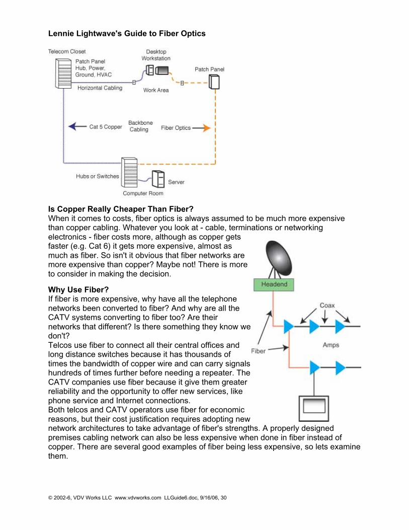
Why Use Fiber?If fiber is more expensive, why have all the telephonenetworks been converted to fiber? And why are all theCATV systems converting to fiber too? Are theirnetworks that different? Is there something they know wedon't?Telcos use fiber to connect all their central offices andlong distance switches because it has thousands oftimes the bandwidth of copper wire and can carry signalshundreds of times further before needing a repeater. TheCATV companies use fiber because it give them greaterreliability and the opportunity to offer new services, likephone service and Internet connections.Both telcos and CATV operators use fiber for economicreasons, but their cost justification requires adopting newnetwork architectures to take advantage of fiber's strengths. A properly designedpremises cabling network can also be less expensive when done in fiber instead ofcopper. There are several good examples of fiber being less expensive, so lets examinethem.
Lennie Lightwave's Guide to Fiber Optics
© 2002-6, VDV Works LLC www.vdvworks.com LLGuide6.doc, 9/16/06, 31
Industrial NetworksIn an industrial environment, electromagnetic interference (EMI) is often a big problem.Motors, relays, welders and other industrial equipment generate a tremendous amountof electrical noise that can cause major problems with copper cabling, especiallyunshielded cable like Cat 5. In order to run copper cable in an industrial environment, itis often necessary to pull it through conduit to provide adequate shielding.With fiber optics, you have complete immunity to EMI. You only need to choose a cabletype that is rugged enough for the installation, with breakout cable being a good choicefor it's heavy-duty construction. The fiber optic cable can be installed easily from point topoint, passing right next to major sources of EMI with no effect. Conversion from coppernetworks is easy with media converters, gadgets that convert most types of systems tofiber optics. Even with the cost of the media converters, the fiber optic network will beless than copper run in conduit.
Long Cable RunsMost networks are designed around structured cabling installed per EIA/TIA 568standards. This standard calls for 90 meters (295 feet) of permanently installedunshielded twisted pair (UTP) cable and 10 meters (33 feet) of patchcords. But supposeyou need to connect two buildings or more? The distance often exceeds the 90 metersby the time you include the runs between the buildings plus what you need inside eachbuilding.By the time you buy special aerial or underground waterproof copper cable andrepeaters, you will usually spend more than if you bought some outside plant fiber opticcable and a couple of inexpensive media converters. It's guaranteed cheaper if you gomore than two links (180 meters.)
Centralized Fiber LANsWhen most contractors and end users look at fiber optics versus Cat 5e cabling for aLAN, they compare the same old copper LAN with fiber directly replacing the copperlinks. The fiber optic cable is a bit more expensive than Cat 5e and terminations are alittle more too, but the big difference is the electronics which are $200 or more per linkextra for fiber.However, the real difference comes if you use a centralized fiber optic network - shownon the right of the diagram above. Since fiber does not have the 90 meter distancelimitation of UTP cable, you can place all electronics in one location in or near thecomputer room. The telecom closet is only used for passive connection of backbonefiber optic cables, so no power, UPS, ground or air conditioning is needed. Theseauxiliary services, necessary with Cat 5 hubs, cost a tremendous amount of money ineach closet.In addition, having all the fiber optic hubs in one location means better utilization of thehardware, with fewer unused ports. Since ports in modular hubs must be added inmodules of 8 or 16, it's not uncommon with a hub in a telecom closet to have many ofthe ports in a module empty . With a centralized fiber system, you can add modulesmore efficiently as you are supporting many more desktop locations but need neverhave more than a one module with open ports.
Lennie Lightwave's Guide to Fiber Optics
© 2002-6, VDV Works LLC www.vdvworks.com LLGuide6.doc, 9/16/06, 32
High Speed NetworkingIt was over a year after Gigabit Ethernet (GbE) became available on fiber optics that itfinally become available on Cat 5e. It took another couple of years before GbE oncopper became significantly less expensive. In order to get GbE to work over Cat 5e,the electronics must be very complicated, and consequently as expensive as fiber. Anewer version is in the wings, awaiting a Cat 6 standard, but that means the versionrunning over Cat 5e will be obsolete before it even gets started! Finally, we went to amajor distributor's seminar on advanced cabling recently and the copper marketing guytold us to go fiber for GbE.
Bottom LineSo when it comes to costs, looking at the cabling component costs may not be a goodway to analyze total network costs. Consider the total system and you may find fiberlooks a lot more attractive.

Lennie Lightwave's Guide to Fiber Optics
© 2002-6, VDV Works LLC www.vdvworks.com LLGuide6.doc, 9/16/06, 33
Estimating and Bidding
Estimating is necessary to figure out what the job will cost you. First of all you'll need toset up a simple chart of all the details: the items you will need to purchase (i.e. cable,connectors, etc) and their costs. You will also need to add labor cost.
Do your homework - be sure to have an accurate idea of how long it takes for eachstep of the installation .
For instance, when dealing with connectors, if a manufacturer says you can terminatehis connector in 3 minutes, test it for yourself in the office before you go to the site. Notonly do you want to know how long it will take, but also how many good ones you get.Are you working on a "tried and true" method such as using epoxy or anaerobicadhesive with ST or SC connectors where installation estimates are well documented ora new system such as MTRJ connectors or a "cleave and leave" connector you havenever done before? Big difference! The newer or more specialized the connector or theinstallation process, the more unpredictable the timing can be. This rule can apply to allthe materials and equipment you will be using. Try to identify who will answer yourquestions from the companies who sold the connectors, cable and the other materialsbefore you go to the job site. This will help avoid serious delays if you run into trouble.
Consider yield. You will never get every connector or splice right the first time. If youget 90% good in the field, you are a hero! Magazines periodically publish articles aboutthe yield of various connectors tested in the field - the yield for certain connectors canbe as low as 30%!
Be sure to visit the job site - you have to see for yourself what the job looks like. Getas much information as you can - walk the route carefully and note things such as whatother cables are there and will they have to be removed, the condition of the buildingand any potential problems with moisture or excessive heat or cold, any inconsistenciesfrom the architectural drawings, what other work is being done at the same time andhow it will effect what you're doing, can you easily get your equipment where it needs tobe. Bring a camera if the customer will let you - take lots of pictures! Trust us, we haveseen every mistake made and more! Double - then triple check everything. You won'tregret it.
Talk to the customer - be sure to understand exactly what will be required of you. Youmust know what types of cable, connectors, splices, hardware, etc. the customer wants(including brands - if specified). Does the customer want employees to be trained? Getall the details on this up front also. Don't be afraid to suggest alternatives that will savehim (and you) money. Research the customer - how long have they been in business?Do they pay their contractors on time? Ask around - if there is a problem, it will probablysurface.Read the specifications carefully - if you see something that doesn't make sense (likethe all too common one of asking for OTDR test data on short LAN cable runs), tell thecustomer your concerns before you bid. Don't bid blindly.

Lennie Lightwave's Guide to Fiber Optics
© 2002-6, VDV Works LLC www.vdvworks.com LLGuide6.doc, 9/16/06, 34
Once you have gathered all your information, you will need to bring your math skills intoplay and create a document (usually a spreadsheet) that allows you to transfer all thisinformation into a "map" of the job that you and your workers can follow. Refer tochapter 14 of "The Fiber Optic Technician's Manual" for an excellent guide on how tocreate this document.
Bidding
Bidding is closely related to estimating, but adds in the profit margin you need to stay inbusiness - don't forget that! If you bid accurately, you will never regret losing a job to alower bidder, because you know that the winning bid is close to or losing money andthat is not the goal of running a business. Bid accurately and you will stay in business!
Documentation
Knowing where every cable, connector, splice, patch panel, etc goes and the length ofevery cable is more than helpful. It can help you in bidding, buying, installation, testing,and restoration. After installation, keep test data to refer back to when you haveproblems.Smart installers understand the value of documentation and understand it can lead tohigher bids, but good documentation pays for itself. Smart users understand it too andare willing to pay for good documentation.
Estimating SoftwareToday you can get several great programs that automate the estimation process. Theycan access databases of costs, aggregate components and do lots more to simplify theprocess. Evaluate all these products - a contractors trade show is a good place to startlooking at them - to see if they meet your needs.
Lennie Lightwave's Guide to Fiber Optics
© 2002-6, VDV Works LLC www.vdvworks.com LLGuide6.doc, 9/16/06, 35
TestingAfter the cables are installed and terminated, it's time for testing. For every fiber opticcable plant, you will need to test for continuity, end-to-end loss and then troubleshootthe problems. If it's a long outside plant cable with intermediate splices, you willprobably want to verify the individual splices with an OTDR also, since that's the onlyway to make sure that each one is good. If you are the network user, you will also beinterested in testing power, as power is the measurement that tells you whether thesystem is operating properly.
You'll need a few special tools and instruments to test fiber optics. See Jargon in thebeginning of Lennie's Guide to see a description of each instrument.
Getting Started
Even if you're an experienced installer, make sure you remember these things.
1. Have the right tools and test equipment for the job...You will need:Source and power meter, optical loss test set or test kit with proper equipment adaptersfor the cable plant you are testing.Reference test cables that match the cables to be tested and mating adapters, includinghybrids if neededFiber Tracer or Visual Fault LocatorCleaning materials - lint free cleaning wipes and pure alcoholOTDR and launch cable for outside plant jobs
2. Know how to use your test equipmentBefore you start, get together all your tools and make sure they are all working properlyand you and your installers know how to use them. It's hard to get the job done whenyou have to call the manufacturer from the job site on your cell phone to ask for help.Try all your equipment in the office before you take it into the field. Use it to test everyone of your reference test jumper cables in both directions using the single-ended losstest to make sure they are all good. If your power meter has internal memory to recorddata be sure you know how to use this also. You can often customize these reports toyour specific needs - figure all this out before you go it the field - it could save you timeand on installations, time is money!
3. Know the network you're testing...This is an important part of the documentation process we discussed earlier. Make sureyou have cable layouts for every fiber you have to test. Prepare a spreadsheet of all thecables and fibers before you go in the field and print a copy for recording your test data.You may record all your test data either by hand or if your meter has a memory feature,it will keep test results in on-board memory that can be printed or transferred to acomputer when you return to the office.
A note on using a fiber optic source eye safety...
Lennie Lightwave's Guide to Fiber Optics
© 2002-6, VDV Works LLC www.vdvworks.com LLGuide6.doc, 9/16/06, 36
Fiber optic sources, including test equipment, are generally too low in power to causeany eye damage, but it's still a good idea to check connectors with a power meterbefore looking into it. Some telco DWDM and CATV systems have very high power andthey could be harmful, so better safe than sorry.
Fiber optic testing includes three basic tests that we will cover separately:Visual inspection for continuity or connector checkingLoss testingNetwork Testing
Visual Inspection
Visual TracingContinuity checking makes certain the fibers are not broken and to trace a path of afiber from one end to another through many connections. Use a visible light "fiber optictracer" or "pocket visual fault locator". It looks like a flashlight or a pen-like instrumentwith a lightbulb or LED soure that mates to a fiber optic connector. Attach a cable to testto the visual tracer and look at the other end to see the light transmitted through thecore of the fiber. If there is no light at the end, go back to intermediate connections tofind the bad section of the cable.
A good example of how it can save time and money is testing fiber on a reel before youpull it to make sure it hasn't been damaged during shipment. Look for visible signs ofdamage (like cracked or broken reels, kinks in the cable, etc.) . For testing, visualtracers help also identify the next fiber to be tested for loss with the test kit. Whenconnecting cables at patch panels, use the visual tracer to make sure each connectionis the right two fibers! And to make certain the proper fibers are connected to thetransmitter and receiver, use the visual tracer in place of the transmitter and your eyeinstead of the receiver (remember that fiber optic links work in the infrared so you can'tsee anything anyway.)
Visual Fault LocationA higher power version of the tracer uses a laser that can also find faults. The red laserlight is powerful enough to show breaks in fibers or high loss connectors. You canactually see the loss of the bright red light even through many yellow or orange simplexcable jackets except black or gray jackets. You can also use this gadget to optimizemechanical splices or prepolished-splice type fiber optic connectors. In fact- don't eventhink of doing one of those connectors without one no other method will assure you ofhigh yield with them.
Visual Connector InspectionFiber optic microscopes are used to inspect connectors to check the quality of thetermination procedure and diagnose problems. A well made connector will have asmooth , polished, scratch free finish and the fiber will not show any signs of cracks,chips or areas where the fiber is either protruding from the end of the ferrule or pullingback into it.
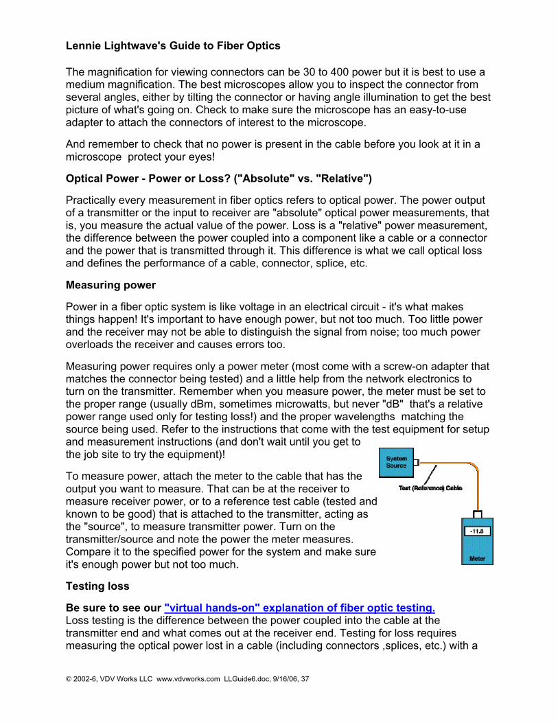
Lennie Lightwave's Guide to Fiber Optics
© 2002-6, VDV Works LLC www.vdvworks.com LLGuide6.doc, 9/16/06, 37
The magnification for viewing connectors can be 30 to 400 power but it is best to use amedium magnification. The best microscopes allow you to inspect the connector fromseveral angles, either by tilting the connector or having angle illumination to get the bestpicture of what's going on. Check to make sure the microscope has an easy-to-useadapter to attach the connectors of interest to the microscope.
And remember to check that no power is present in the cable before you look at it in amicroscope protect your eyes!
Optical Power - Power or Loss? ("Absolute" vs. "Relative")
Practically every measurement in fiber optics refers to optical power. The power outputof a transmitter or the input to receiver are "absolute" optical power measurements, thatis, you measure the actual value of the power. Loss is a "relative" power measurement,the difference between the power coupled into a component like a cable or a connectorand the power that is transmitted through it. This difference is what we call optical lossand defines the performance of a cable, connector, splice, etc.
Measuring power
Power in a fiber optic system is like voltage in an electrical circuit - it's what makesthings happen! It's important to have enough power, but not too much. Too little powerand the receiver may not be able to distinguish the signal from noise; too much poweroverloads the receiver and causes errors too.
Measuring power requires only a power meter (most come with a screw-on adapter thatmatches the connector being tested) and a little help from the network electronics toturn on the transmitter. Remember when you measure power, the meter must be set tothe proper range (usually dBm, sometimes microwatts, but never "dB" that's a relativepower range used only for testing loss!) and the proper wavelengths matching thesource being used. Refer to the instructions that come with the test equipment for setupand measurement instructions (and don't wait until you get tothe job site to try the equipment)!
To measure power, attach the meter to the cable that has theoutput you want to measure. That can be at the receiver tomeasure receiver power, or to a reference test cable (tested andknown to be good) that is attached to the transmitter, acting asthe "source", to measure transmitter power. Turn on thetransmitter/source and note the power the meter measures.Compare it to the specified power for the system and make sureit's enough power but not too much.
Testing loss
Be sure to see our "virtual hands-on" explanation of fiber optic testing.Loss testing is the difference between the power coupled into the cable at thetransmitter end and what comes out at the receiver end. Testing for loss requiresmeasuring the optical power lost in a cable (including connectors ,splices, etc.) with a
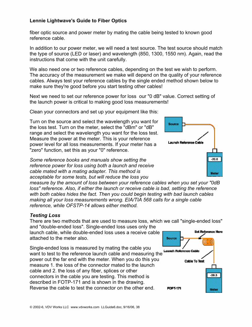
Lennie Lightwave's Guide to Fiber Optics
© 2002-6, VDV Works LLC www.vdvworks.com LLGuide6.doc, 9/16/06, 38
fiber optic source and power meter by mating the cable being tested to known goodreference cable.
In addition to our power meter, we will need a test source. The test source should matchthe type of source (LED or laser) and wavelength (850, 1300, 1550 nm). Again, read theinstructions that come with the unit carefully.
We also need one or two reference cables, depending on the test we wish to perform.The accuracy of the measurement we make will depend on the quality of your referencecables. Always test your reference cables by the single ended method shown below tomake sure they're good before you start testing other cables!
Next we need to set our reference power for loss our "0 dB" value. Correct setting ofthe launch power is critical to making good loss measurements!
Clean your connectors and set up your equipment like this:
Turn on the source and select the wavelength you want forthe loss test. Turn on the meter, select the "dBm" or "dB"range and select the wavelength you want for the loss test.Measure the power at the meter. This is your referencepower level for all loss measurements. If your meter has a"zero" function, set this as your "0" reference.
Some reference books and manuals show setting thereference power for loss using both a launch and receivecable mated with a mating adapter. This method isacceptable for some tests, but will reduce the loss youmeasure by the amount of loss between your reference cables when you set your "0dBloss" reference. Also, if either the launch or receive cable is bad, setting the referencewith both cables hides the fact. Then you could begin testing with bad launch cablesmaking all your loss measurements wrong. EIA/TIA 568 calls for a single cablereference, while OFSTP-14 allows either method.
Testing LossThere are two methods that are used to measure loss, which we call "single-ended loss"and "double-ended loss". Single-ended loss uses only thelaunch cable, while double-ended loss uses a receive cableattached to the meter also.
Single-ended loss is measured by mating the cable youwant to test to the reference launch cable and measuring thepower out the far end with the meter. When you do this youmeasure 1. the loss of the connector mated to the launchcable and 2. the loss of any fiber, splices or otherconnectors in the cable you are testing. This method isdescribed in FOTP-171 and is shown in the drawing.Reverse the cable to test the connector on the other end.
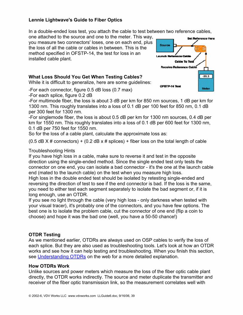
Lennie Lightwave's Guide to Fiber Optics
© 2002-6, VDV Works LLC www.vdvworks.com LLGuide6.doc, 9/16/06, 39
In a double-ended loss test, you attach the cable to test between two reference cables,one attached to the source and one to the meter. This way,you measure two connectors' loses, one on each end, plusthe loss of all the cable or cables in between. This is themethod specified in OFSTP-14, the test for loss in aninstalled cable plant.
What Loss Should You Get When Testing Cables?While it is difficult to generalize, here are some guidelines:
-For each connector, figure 0.5 dB loss (0.7 max)-For each splice, figure 0.2 dB-For multimode fiber, the loss is about 3 dB per km for 850 nm sources, 1 dB per km for1300 nm. This roughly translates into a loss of 0.1 dB per 100 feet for 850 nm, 0.1 dBper 300 feet for 1300 nm.-For singlemode fiber, the loss is about 0.5 dB per km for 1300 nm sources, 0.4 dB perkm for 1550 nm. This roughly translates into a loss of 0.1 dB per 600 feet for 1300 nm,0.1 dB per 750 feet for 1550 nm.So for the loss of a cable plant, calculate the approximate loss as:
(0.5 dB X # connectors) + (0.2 dB x # splices) + fiber loss on the total length of cable
Troubleshooting HintsIf you have high loss in a cable, make sure to reverse it and test in the oppositedirection using the single-ended method. Since the single ended test only tests theconnector on one end, you can isolate a bad connector - it's the one at the launch cableend (mated to the launch cable) on the test when you measure high loss.High loss in the double ended test should be isolated by retesting single-ended andreversing the direction of test to see if the end connector is bad. If the loss is the same,you need to either test each segment separately to isolate the bad segment or, if it islong enough, use an OTDR.If you see no light through the cable (very high loss - only darkness when tested withyour visual tracer), it's probably one of the connectors, and you have few options. Thebest one is to isolate the problem cable, cut the connector of one end (flip a coin tochoose) and hope it was the bad one (well, you have a 50-50 chance!)
OTDR TestingAs we mentioned earlier, OTDRs are always used on OSP cables to verify the loss ofeach splice. But they are also used as troubleshooting tools. Let's look at how an OTDRworks and see how it can help testing and troubleshooting. When you finish this section,see Understanding OTDRs on the web for a more detailed explanation.
How OTDRs WorkUnlike sources and power meters which measure the loss of the fiber optic cable plantdirectly, the OTDR works indirectly. The source and meter duplicate the transmitter andreceiver of the fiber optic transmission link, so the measurement correlates well with
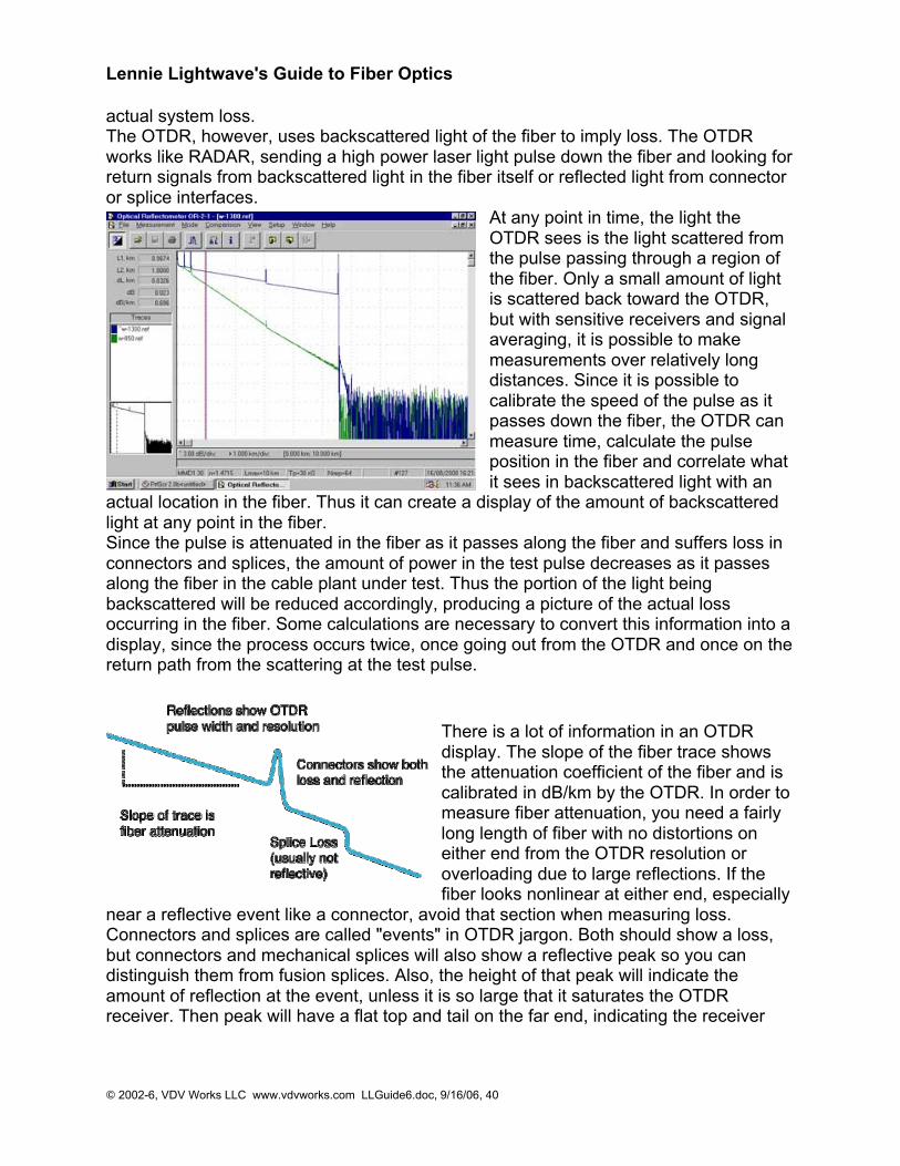
Lennie Lightwave's Guide to Fiber Optics
© 2002-6, VDV Works LLC www.vdvworks.com LLGuide6.doc, 9/16/06, 40
actual system loss.The OTDR, however, uses backscattered light of the fiber to imply loss. The OTDRworks like RADAR, sending a high power laser light pulse down the fiber and looking forreturn signals from backscattered light in the fiber itself or reflected light from connectoror splice interfaces.
At any point in time, the light theOTDR sees is the light scattered fromthe pulse passing through a region ofthe fiber. Only a small amount of lightis scattered back toward the OTDR,but with sensitive receivers and signalaveraging, it is possible to makemeasurements over relatively longdistances. Since it is possible tocalibrate the speed of the pulse as itpasses down the fiber, the OTDR canmeasure time, calculate the pulseposition in the fiber and correlate whatit sees in backscattered light with an
actual location in the fiber. Thus it can create a display of the amount of backscatteredlight at any point in the fiber.Since the pulse is attenuated in the fiber as it passes along the fiber and suffers loss inconnectors and splices, the amount of power in the test pulse decreases as it passesalong the fiber in the cable plant under test. Thus the portion of the light beingbackscattered will be reduced accordingly, producing a picture of the actual lossoccurring in the fiber. Some calculations are necessary to convert this information into adisplay, since the process occurs twice, once going out from the OTDR and once on thereturn path from the scattering at the test pulse.
There is a lot of information in an OTDRdisplay. The slope of the fiber trace showsthe attenuation coefficient of the fiber and iscalibrated in dB/km by the OTDR. In order tomeasure fiber attenuation, you need a fairlylong length of fiber with no distortions oneither end from the OTDR resolution oroverloading due to large reflections. If thefiber looks nonlinear at either end, especially
near a reflective event like a connector, avoid that section when measuring loss.Connectors and splices are called "events" in OTDR jargon. Both should show a loss,but connectors and mechanical splices will also show a reflective peak so you candistinguish them from fusion splices. Also, the height of that peak will indicate theamount of reflection at the event, unless it is so large that it saturates the OTDRreceiver. Then peak will have a flat top and tail on the far end, indicating the receiver
Lennie Lightwave's Guide to Fiber Optics
© 2002-6, VDV Works LLC www.vdvworks.com LLGuide6.doc, 9/16/06, 41
was overloaded. The width of the peak shows the distance resolution of the OTDR, orhow close it can detect events.
OTDRs can also detect problems in the cable caused during installation. If a fiber isbroken, it will show up as the end of the fiber much shorter than the cable or a high losssplice at the wrong place. If excessive stress is placed on the cable due to kinking or tootight a bend radius, it will look like a splice at the wrong location.
OTDR LimitationsThe limited distance resolution of the OTDR makes it very hard to use in a LAN orbuilding environment where cables are usually only a few hundred meters long. TheOTDR has a great deal of difficulty resolving features in the short cables of a LAN and islikely to show "ghosts" from reflections at connectors, more often than not simplyconfusing the user.
Using The OTDRWhen using an OTDR, there are a few cautions that will make testing easier and moreunderstandable. First always use a long launch cable, which allows the OTDR to settledown after the initial pulse and provides a reference cable for testing the first connectoron the cable. Always start with the OTDR set for the shortest pulse width for bestresolution and a range at least 2 times the length of the cable you are testing. Make aninitial trace and see how you need to change the parameters to get better results.
The VDV Works online OTDR tutorial will teach you a lot more about OTDRs!
RestorationThe time may come when you have to troubleshoot and fix the cable plant. If you have acritical application or lots of network cable, you should be ready to do it yourself.Smaller networks can rely on a contractor. If you plan to do it yourself, you need to haveequipment ready (extra cables, mechanical splices, quick termination connectors, etc.,plus test equipment.) and someone who knows how to use it.We cannot emphasize more strongly the need to have good documentation on thecable plant. If you don't know where the cables go, how long they are or what theytested for loss, you will be spinning you wheels from the get-go. And you need tools todiagnose problems and fix them, and spares including a fusion splicer or somemechanical splices and spare cables. In fact, when you install cable, save the leftoversfor restoration!And the first thing you must decide is if the problem is with the cables or the equipmentusing it. A simple power meter can test sources for output and receivers for input and avisual tracer will check for fiber continuity. If the problem is in the cable plant, the OTDRis the next tool needed to locate the fault.

Lennie Lightwave's Guide to Fiber Optics
© 2002-6, VDV Works LLC www.vdvworks.com LLGuide6.doc, 9/16/06, 42
Getting More Training
Now that Lennie's Guide has provided you with the basics, you're probably ready tofigure out where to go from here. There are many options for further training but first youneed to figure out what your career choice is.
If you want to work in engineering for a component manufacturer, you will need to learnthe theory behind the technology, so you will probably need to start with university levelclasses in physics and add classes in electronics, optics and fiber optics. If you want todesign networks, you probably need a university education in electronics andcommunications system design.
If you just want to understand the technology so you can design, install and maintaincable plants and networks for LANS, CATV systems, utilities, etc. you need to knowvery little about the theory itself, but lots about cables, connectors and hardware andhow cable plants are designed, installed and tested. Your training should focus onpractical knowledge and lots of hands-on exercises. Work toward getting your CertifiedFiber Optic Technican certification from The FOA.
Whatever your interest, make sure the courses you take are appropriate for yourinterests or you'll be wasting time and money. Here are some options to consider:
Jim Hayes of VDV Works teaches a seminar at NECA's VDV Expo
Seminars - can run from one day to two weeks and cost nothing to several thousanddollars. Make sure any seminar you attend is focused on what aspect of fiber optics youwant to learn and has lots of hands-on exercises. Also remember that company-sponsored seminars can be narrowly focussed on their products only. If you plan onusing this equipment it can be a real deal!
Continuing Education - Technical schools are now offering cable installation courses,usually one or two nights a week for ten to twelve sessions. The big advantage of thesecourses is the extra time involved, usually more than twice as much as would beavailable in a seminar. As a result, you get more time to ask questions, practice hands-
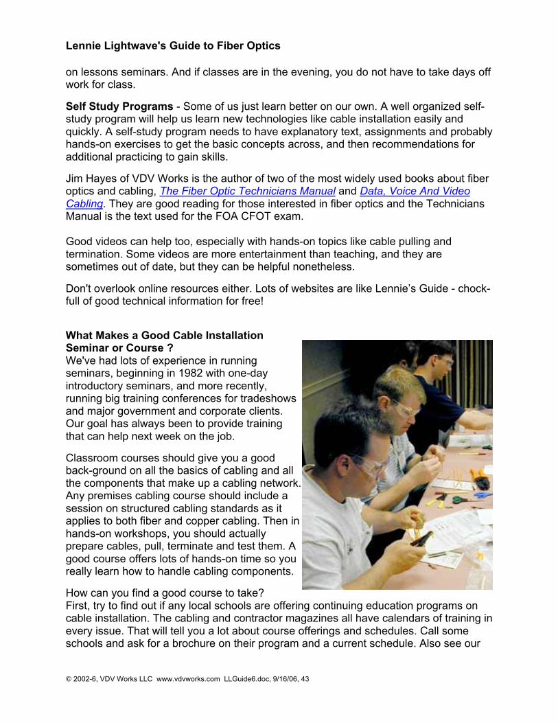
Lennie Lightwave's Guide to Fiber Optics
© 2002-6, VDV Works LLC www.vdvworks.com LLGuide6.doc, 9/16/06, 43
on lessons seminars. And if classes are in the evening, you do not have to take days offwork for class.
Self Study Programs - Some of us just learn better on our own. A well organized self-study program will help us learn new technologies like cable installation easily andquickly. A self-study program needs to have explanatory text, assignments and probablyhands-on exercises to get the basic concepts across, and then recommendations foradditional practicing to gain skills.
Jim Hayes of VDV Works is the author of two of the most widely used books about fiberoptics and cabling, The Fiber Optic Technicians Manual and Data, Voice And VideoCabling. They are good reading for those interested in fiber optics and the TechniciansManual is the text used for the FOA CFOT exam.
Good videos can help too, especially with hands-on topics like cable pulling andtermination. Some videos are more entertainment than teaching, and they aresometimes out of date, but they can be helpful nonetheless.
Don't overlook online resources either. Lots of websites are like Lennie’s Guide - chock-full of good technical information for free!
What Makes a Good Cable InstallationSeminar or Course ?We've had lots of experience in runningseminars, beginning in 1982 with one-dayintroductory seminars, and more recently,running big training conferences for tradeshowsand major government and corporate clients.Our goal has always been to provide trainingthat can help next week on the job.
Classroom courses should give you a goodback-ground on all the basics of cabling and allthe components that make up a cabling network.Any premises cabling course should include asession on structured cabling standards as itapplies to both fiber and copper cabling. Then inhands-on workshops, you should actuallyprepare cables, pull, terminate and test them. Agood course offers lots of hands-on time so youreally learn how to handle cabling components.
How can you find a good course to take?First, try to find out if any local schools are offering continuing education programs oncable installation. The cabling and contractor magazines all have calendars of training inevery issue. That will tell you a lot about course offerings and schedules. Call someschools and ask for a brochure on their program and a current schedule. Also see our

Lennie Lightwave's Guide to Fiber Optics
© 2002-6, VDV Works LLC www.vdvworks.com LLGuide6.doc, 9/16/06, 44
VDV Works website to see where our programs are being given or forrecommendations on other programs. Also, get recommendations from students thathave taken courses or talk to instructors in related fields. Training can be a biginvestment, so be thorough!
How can you get certification ?Who certifies cabling technicians? Well, it seems every trainer, manufacturer andvendor offers a "certificate" to everybody who completes their class. None of them, ofcourse, recognize the other's certificate and neither do most of your customers!Fortunately, there is a professional society for fiber optics, The Fiber Optic Association,that offers certification to those who pass a qualifying test and can show related workexperience. The FOA also approves training schools that meet their academic criteria.To be recognized as a professional in fiber optics, becoming a member of the FOA andpassing certification exam, see the FOA website: www.thefoa.org. For structuredcabling, the SCA, www.scausa.org, is the place to go.

Lennie Lightwave's Guide to Fiber Optics
© 2002-6, VDV Works LLC www.vdvworks.com LLGuide6.doc, 9/16/06, 45
Glossary
Here's an alphabetical glossary of fiber optic terms.
AAbsorption: That portion of fiber optic attenuation resulting of conversion of opticalpower to heat.Analog: Signals that are continually changing, as opposed to being digitally encoded.Attenuation Coefficient: Characteristic of the attenuation of an optical fiber per unitlength, in dB/km.Attenuation: The reduction in optical power as it passes along a fiber, usually expressedin decibels (dB). See optical loss.Attenuator: A device that reduces signal power in a fiber optic link by inducing loss.Average power: The average over time of a modulated signal.
BBack reflection, optical return loss: Light reflected from the cleaved or polished end of afiber caused by the difference of refractive indices of air and glass. Typically 4% of theincident light. Expressed in dB relative to incident power.Backscattering: The scattering of light in a fiber back toward the source, used to makeOTDR measurements. Bandwidth: The range of signal frequencies or bit rate withinwhich a fiber optic component, link or network will operate.Bending loss, microbending loss: Loss in fiber caused by stress on the fiber bent arounda restrictive radius. Bit-error rate (BER): The fraction of data bits transmitted that arereceived in error.Bit: An electrical or optical pulse that carries information.Buffer: A protective coating applied directly on the fiber.
CCable: One or more fibers enclosed in protective coverings and strength members.Cable Plant, Fiber Optic: The combination of fiber optic cable sections, connectors andsplices forming the optical path between two terminal devices.CATV: An abbreviation for Community Antenna Television or cable TV.Chromatic dispersion: The temporal spreading of a pulse in an optical waveguidecaused by the wavelength dependence of the velocities of light.Cladding: The lower refractive index optical coating over the core of the fiber that "traps"light into the core. Connector: A device that provides for a demountable connectionbetween two fibers or a fiber and an active device and provides protection for the fiber.Core: The center of the optical fiber through which light is transmitted.Coupler: An optical device that splits or combines light from more than one fiber.Cutback method: A technique for measuring the loss of bare fiber by measuring theoptical power transmitted through a long length then cutting back to the source andmeasuring the initial coupled power.Cutoff wavelength: The wavelength beyond which singlemode fiber only supports onemode of propagation.
Lennie Lightwave's Guide to Fiber Optics
© 2002-6, VDV Works LLC www.vdvworks.com LLGuide6.doc, 9/16/06, 46
DdBm: Optical power referenced to 1 milliwatt.Decibel (dB): A unit of measurement of optical power which indicates relative power ona logarithmic scale, sometimes called dBr. dB=10 log ( power ratio)Detector: A photodiode that converts optical signals to electrical signals.Digital: Signals encoded into discrete bits.Dispersion: The temporal spreading of a pulse in an optical waveguide. May be causedby modal or chromatic effects.
EEDFA: Erbium-doped fiber amplifier, an all optical amplifier for 1550 nm SMtransmissionsystems.Edge-emitting diode (E-LED): A LED that emits from the edge of the semiconductorchip, producing higher power and narrower spectral width.End finish: The quality of the end surface of a fiber prepared for splicing or terminated ina connector.Equilibrium modal distribution (EMD): Steady state modal distribution in multimode fiber,achieved some distance from the source, where the relative power in the modesbecomes stable with increasing distance.ESCON: IBM standard for connecting peripherals to a computer over fiber optics.Acronym for Enterprise System Connection.Excess loss: The amount of light lost in a coupler, beyond that inherent in the splitting tomultiple output fibers.
FFiber Amplifier: an all optical amplifier using erbium or other doped fibers and pumplasers to increase signal output power without electronic conversion.Fiber Distributed Data Interface, FDDI: 100 Mb/s ring architecture data network.Ferrule: A precision tube which holds a fiber for alignment for interconnection ortermination. A ferrule may be part of a connector or mechanical splice.Fiber tracer: An instrument that couples visible light into the fiber to allow visualchecking of continuity and tracing for correct connections.Fiber identifier: A device that clamps onto a fiber and couples light from the fiber bybending, to identify the fiber and detect high speed traffic of an operating link or a 2 kHztone injected by a test source.Fiber optics: Light transmission through flexible transmissive fibers for communicationsor lighting.FO: Common abbreviation for "fiber optic."Fresnel reflection, back reflection, optical return loss: Light reflected from the cleaved orpolished end of a fiber caused by the difference of refractive indices of air and glass.Typically 4% of the incident light.Fusion splicer: An instrument that splices fibers by fusing or welding them, typically byelectrical arc.
Lennie Lightwave's Guide to Fiber Optics
© 2002-6, VDV Works LLC www.vdvworks.com LLGuide6.doc, 9/16/06, 47
GGraded index (GI): A type of multimode fiber which used a graded profile of refractiveindex in the core material to correct for dispersion.
IIndex of refraction: A measure of the speed of light in a material.Index matching fluid: A liquid used of refractive index similar to glass used to match thematerials at the ends of two fibers to reduce loss and back reflection.Index profile: The refractive index of a fiber as a function of cross section.Insertion loss: The loss caused by the insertion of a component such as a splice orconnector in an optical fiber.
JJacket: The protective outer coating of the cable.Jumper cable: A short single fiber cable with connectors on both ends used forinterconnecting other cables or testing.
LLaser diode, ILD: A semiconductor device that emits high powered, coherent light whenstimulated by an electrical current. Used in transmitters for singlemode fiber links.Launch cable: A known good fiber optic jumper cable attached to a source andcalibrated for output power used used as a reference cable for loss testing. This cablemust be made of fiber and connectors of a matching type to the cables to be tested.Light-emitting diode, LED: A semiconductor device that emits light when stimulated byan electrical current. Used in transmitters for multimode fiber links.Link, fiber optic: A combination of transmitter, receiver and fiber optic cable connectingthem capable of transmitting data. May be analog or digital.Long wavelength: A commonly used term for light in the 1300 and 1550 nm ranges.Loss,optical: The amount of optical power lost as light is transmitted through fiber,splices, couplers, etc.Loss budget: The amount of power lost in the link. Often used in terms of the maximumamount of loss that can be tolerated by a given link.
MMargin: The additional amount of loss that can be tolerated in a link.Mechanical splice: A semi-permanent connection between two fibers made with analignment device and index matching fluid or adhesive.Micron (*m): A unit of measure, 10-6 m, used to measure wavelength of light.Microscope, fiber optic inspection: A microscope used to inspect the end surface of aconnector for flaws or contamination or a fiber for cleave quality.Modal dispersion: The temporal spreading of a pulse in an optical waveguide caused bymodal effects.Mode field diameter: A measure of the core size in singlemode fiber.Mode filter: A device that removes optical power in higher order modes in fiber.Mode scrambler: A device that mixes optical power in fiber to achieve equal powerdistribution in all modes. Mode stripper: A device that removes light in the cladding of an
Lennie Lightwave's Guide to Fiber Optics
© 2002-6, VDV Works LLC www.vdvworks.com LLGuide6.doc, 9/16/06, 48
optical fiber.Mode: A single electromagnetic field pattern that travels in fiber.Multimode fiber: A fiber with core diameter much larger than the wavelength of lighttransmitted that allows many modes of light to propagate. Commonly used with LEDsources for lower speed, short distance links.
NNanometer (nm): A unit of measure , 10-9 m, used to measure the wavelength of light.Network: A system of cables, hardware and equipment used for communications.Numerical aperture (NA): A measure of the light acceptance angle of the fiber.
OOptical amplifier: A device that amplifies light without converting it to an electrical signal.Optical fiber: An optical waveguide, comprised of a light carrying core and claddingwhich traps light in the core.Optical loss test set (OLTS): An measurement instrument for optical loss that includesboth a meter and source.Optical power: The amount of radiant energy per unit time, expressed in linear units ofWatts or on a logarithmic scale, in dBm (where 0 dB = 1 mW) or dB* (where 0 dB*=1microWatt).Optical return loss, back reflection: Light reflected from the cleaved or polished end of afiber caused by the difference of refractive indices of air and glass. Typically 4% of theincident light. Expressed in dB relative to incident power.Optical switch: A device that routes an optical signal from one or more input ports to oneor more output ports.Optical time domain reflectometer (OTDR): An instruments that used backscattered lightto find faults in optical fiber and infer loss.Overfilled launch: A condition for launching light into the fiber where the incoming lighthas a spot size and NA larger than accepted by the fiber, filling all modes in the fiber.
PPhotodiode: A semiconductor that converts light to an electrical signal, used in fiberoptic receivers.Pigtail: A short length of fiber attached to a fiber optic component such as a laser orcoupler.Plastic optical fiber (POF): An optical fiber made of plastic.Plastic-clad silica (PCS) fiber: A fiber made with a glass core and plastic cladding.Power budget: The difference (in dB) between the transmitted optical power (in dBm)and the receiver sensitivity (in dBm).Power meter, fiber optic: An instrument that measures optical power emanating form theend of a fiber.Preform: The large diameter glass rod from which fiber is drawn.
RReceive cable: A known good fiber optic jumper cable attached to a power meter usedas a reference cable for loss testing. This cable must be made of fiber and connectors
Lennie Lightwave's Guide to Fiber Optics
© 2002-6, VDV Works LLC www.vdvworks.com LLGuide6.doc, 9/16/06, 49
of a matching type to the cables to be tested.Receiver: A device containing a photodiode and signal conditioning circuitry thatconverts light to an electrical signal in fiber optic links.Refractive index: A property of optical materials that relates to the velocity of light in thematerial.Repeater, regenerator: A device that receives a fiber optic signal and regenerates it forretransmission, used in very long fiber optic links.
SScattering: The change of direction of light after striking small particles that causes lossin optical fibers.Short wavelength: A commonly used term for light in the 665, 790, and 850 nm ranges.Singlemode fiber: A fiber with a small core, only a few times the wavelength of lighttransmitted, that only allows one mode of light to propagate. Commonly used with lasersources for high speed, long distance links.Source: A laser diode or LED used to inject an optical signal into fiber.Splice (fusion or mechanical): A device that provides for a connection between twofibers, typically intended to be permanent.Splitting ratio: The distribution of power among the output fibers of a coupler.Steady state modal distribution: Equilibrium modal distribution (EMD) in multimode fiber,achieved some distance from the source, where the relative power in the modesbecomes stable with increasing distance.Step index fiber: A multimode fiber where the core is all the same index of refraction.Surface emitter LED: A LED that emits light perpendicular to the semiconductor chip.Most LEDs used in datacommunications are surface emitters.
TTalkset, fiber optic: A communication device that allows conversation over unusedfibers.Termination: Preparation of the end of a fiber to allow connection to another fiber or anactive device, sometimes also called "connectorization".Test cable: A short single fiber jumper cable with connectors on both ends used fortesting. This cable must be made of fiber and connectors of a matching type to thecables to be tested.Test kit: A kit of fiber optic instruments, typically including a power meter, source andtest accessories used for measuring loss and power.Test source: A laser diode or LED used to inject an optical signal into fiber for testingloss of the fiber or other components.Total internal reflection: Confinement of light into the core of a fiber by the reflection offthe core-cladding boundary.Transmitter: A device which includes a LED or laser source and signal conditioningelectronics that is used to inject a signal into fiber.
VVCSEL: vertical cavity surface emitting laser, a type of laser that emits light verticallyout of the chip, not out the edge.

Lennie Lightwave's Guide to Fiber Optics
© 2002-6, VDV Works LLC www.vdvworks.com LLGuide6.doc, 9/16/06, 50
Visual fault locator: A device that couples visible light into the fiber to allow visual tracingand testing of continuity. Some are bright enough to allow finding breaks in fiber throughthe cable jacket.
WWatts: A linear measure of optical power, usually expressed in milliwatts (mW),microwatts (*W) or nanowatts (nW).Wavelength: A measure of the color of light, usually expressed in nanometers (nm) ormicrons (*m).Wavelength division multiplexing (WDM): A technique of sending signals of severaldifferent wavelengths of light into the fiber simultaneously.Working margin: The difference (in dB) between the power budget and the loss budget(i.e. the excess power margin).